JP6257149B2 - Static induction equipment coil - Google Patents
Static induction equipment coil Download PDFInfo
- Publication number
- JP6257149B2 JP6257149B2 JP2013031669A JP2013031669A JP6257149B2 JP 6257149 B2 JP6257149 B2 JP 6257149B2 JP 2013031669 A JP2013031669 A JP 2013031669A JP 2013031669 A JP2013031669 A JP 2013031669A JP 6257149 B2 JP6257149 B2 JP 6257149B2
- Authority
- JP
- Japan
- Prior art keywords
- coil
- lead portion
- tap
- conductor
- tap lead
- Prior art date
- Legal status (The legal status is an assumption and is not a legal conclusion. Google has not performed a legal analysis and makes no representation as to the accuracy of the status listed.)
- Active
Links
Images


Classifications
-
- H—ELECTRICITY
- H01—ELECTRIC ELEMENTS
- H01F—MAGNETS; INDUCTANCES; TRANSFORMERS; SELECTION OF MATERIALS FOR THEIR MAGNETIC PROPERTIES
- H01F29/00—Variable transformers or inductances not covered by group H01F21/00
- H01F29/02—Variable transformers or inductances not covered by group H01F21/00 with tappings on coil or winding; with provision for rearrangement or interconnection of windings
-
- H—ELECTRICITY
- H01—ELECTRIC ELEMENTS
- H01F—MAGNETS; INDUCTANCES; TRANSFORMERS; SELECTION OF MATERIALS FOR THEIR MAGNETIC PROPERTIES
- H01F41/00—Apparatus or processes specially adapted for manufacturing or assembling magnets, inductances or transformers; Apparatus or processes specially adapted for manufacturing materials characterised by their magnetic properties
- H01F41/02—Apparatus or processes specially adapted for manufacturing or assembling magnets, inductances or transformers; Apparatus or processes specially adapted for manufacturing materials characterised by their magnetic properties for manufacturing cores, coils, or magnets
- H01F41/04—Apparatus or processes specially adapted for manufacturing or assembling magnets, inductances or transformers; Apparatus or processes specially adapted for manufacturing materials characterised by their magnetic properties for manufacturing cores, coils, or magnets for manufacturing coils
- H01F41/06—Coil winding
- H01F41/076—Forming taps or terminals while winding, e.g. by wrapping or soldering the wire onto pins, or by directly forming terminals from the wire
Description
本発明は、高さを低減することで小型化を実現する静止誘導機器コイルに関する。 The present invention relates to a stationary induction device coil that achieves miniaturization by reducing its height.
従来、変圧器等に用いられる静止誘導器コイルの小型化を図るべく種々の方法・構成が開示されている。 Conventionally, various methods and configurations have been disclosed in order to reduce the size of a static inductor coil used in a transformer or the like.
例えば、本願出願人は特開2010−28150号公報(特許文献1)を開示している。
この特許文献1には、「導体をコイル径方向の外周から内周に向かって複数回巻付けて段を形成したあとコイル軸方向に段上りして、コイル径方向の内周から外周に向かって複数回巻付けて次の段を形成し、所望の巻数まで巻回するとともに、タップ線を設けた静止誘導機器コイルにおいて、タップとタップの間の巻き回数をT1とし、1段あたりのコイル径方向の巻数をAとすると、mを整数として下記、式1を満たすことを特徴とした。
T1=2mA−n(式1)
但し、nは1段当たり(A−1)ターンの段数」
とするコイルの構造が開示されている。
For example, the present applicant has disclosed JP 2010-28150 (Patent Document 1).
This
T1 = 2 mA-n (Formula 1)
Where n is the number of (A-1) turns per stage.
A coil structure is disclosed.
しかしながら、上述した技術では未だ、以下のように改善が必要な点があった。即ち、エッジワイズ巻線のタップ引出し部において、タップ引出し部を必ずコイルの外周ターンとするとともに各タップ引き出し部間の絶縁距離を確保するため、コイルの軸方向に3段以上空けてタップ引き出し線を設けるような巻線構造としており、この巻線構造ではコイル高さが高くなり、コイルとして用いる導体は長く、樹脂層が大きくなることから変圧器全体が大型化してしまい、更には変圧器の材料費が高くなってしまっていた。 However, the above-described technique still requires improvement as follows. That is, in the tap lead portion of the edgewise winding, the tap lead portion is always used as the outer peripheral turn of the coil, and in order to secure an insulation distance between the tap lead portions, the tap lead wire is provided with three or more steps in the axial direction of the coil. In this winding structure, the coil height is high, the conductor used as the coil is long, the resin layer is large, and the entire transformer is enlarged, and further, the transformer Material costs were high.
本発明は、上記課題を解決するためになされたものであり、導体をコイル径方向の外周から内周に向かって複数回巻付けて段を形成したあとコイル軸方向に段上りして、コイル径方向の内周から外周に向かって複数回巻付けて次の段を形成し、これを繰り返して所望の巻数まで巻回して形成したコイルである。前記導体は、タップリード線が取り付けられるタップ引出し部を複数有しており、前記タップ引出し部は、前記コイルの最外周に配置されている。複数の前記タップ引出し部は、前記コイルの段のうち前記タップ引出し部が設けられていない段の最外周の導体部分よりもコイル径外方向に突出した第一の引出し部と、前記第一の引出し部よりもコイル径外方向への突出量が大きい第二の引出し部とを含む。また、前記第一の引出し部と、前記第二の引出し部とは、前記コイル軸方向に沿って交互に繰り返し配置され、任意の2つの前記タップ引出し部間の距離は、絶縁距離以上である。上記のようなコイルの構成によれば、巻線スペースを効率化でき、各タップ間の絶縁距離を確保しつつコイル高さ低減を図れる。 The present invention has been made in order to solve the above-described problem, and after forming a step by winding a conductor a plurality of times from the outer periphery to the inner periphery in the coil radial direction, the coil is stepped up in the coil axial direction, and the coil It is a coil formed by winding a plurality of turns from the radially inner periphery to the outer periphery to form the next stage and repeating this to a desired number of turns. The conductor has a plurality of tap lead portions to which tap lead wires are attached, and the tap lead portions are arranged on the outermost periphery of the coil. The plurality of tap lead portions include a first lead portion projecting outward in the coil diameter from the outermost conductor portion of the step of the coil where the tap lead portion is not provided, and the first lead portion. And a second lead portion having a larger amount of protrusion in the outer diameter direction than the lead portion. Further, the first lead portion and the second lead portion are alternately and repeatedly arranged along the coil axis direction, and a distance between any two of the tap lead portions is equal to or greater than an insulation distance. . According to the configuration of the coil as described above, the winding space can be made efficient, and the coil height can be reduced while securing the insulation distance between the taps.
本発明によれば、静止誘導機器コイルの高さを低減でき、より小型で軽量、且つ経済的な静止誘導機器コイルを提供可能となる。 ADVANTAGE OF THE INVENTION According to this invention, the height of a static induction device coil can be reduced, and a smaller, lighter, and more economical static induction device coil can be provided.
以下、本発明の静止誘導機器コイルの実施例について、図面を用いて説明する。
本発明の実施例について、図1乃至7に基づいて説明する。本実施例は、平角線導体をコイルの円筒形方向に巻き付けた段を軸方向に積層し、タップを設けて構成したコイルである。図1は、本実施例に適用するコイルの例としてモールドコイル10を示す。導体1の巻始め3をコイル外側の端部から行い、図1中の導体1に付した数字の順にコイル径方向の外周から内周へ向かって複数回巻付けて段を形成したあと、上段へ上がり次に内周から外周へ向かって巻き付ける。これを規定の巻数まで繰り返すことでコイルの形状とし、樹脂層2を形成する。
Hereinafter, embodiments of the static induction device coil of the present invention will be described with reference to the drawings.
An embodiment of the present invention will be described with reference to FIGS. The present embodiment is a coil in which a step in which a flat wire conductor is wound in the cylindrical direction of the coil is laminated in the axial direction and a tap is provided. FIG. 1 shows a
本実施例の樹脂モールドコイルは、平角線を成形してエッジワイズに曲げ加工を行いながらコイルを成形するものである。特に矩形形状のコイルのときは、平角線を直線部と曲げ部に分け、それぞれ異なる成形方法を行う。たとえば、図2(a)(b)に示すコイル成形機を使用し、上下に設置されたローラ5、5の間に平角線1を通し、電線成形部4によりローラ5の角度を変更させることで導体1にRの癖を付ける。この方法によれば、任意のRを有する平角線からなる導体1を成形出来、また丸型コイル、矩形コイルとも製作可能である。成形中のコイルの斜視図を図3に示す。
The resin-molded coil according to the present embodiment is for forming a coil while forming a flat wire and bending it edgewise. In particular, in the case of a rectangular coil, the flat wire is divided into a straight portion and a bent portion, and different forming methods are performed. For example, using the coil forming machine shown in FIGS. 2 (a) and 2 (b), the
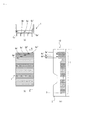
かかるコイルにおいて、図4(a)〜(c)に示すようにコイルをその巻始め部3から巻き終りまで成形し、このコイルからタップ電圧に応じた所定の巻き回数よりタップリード線を取り付ける導体部分(タップ引出し部)6a〜6eとタップ切換部のタップ端子とをタップリード線で接続する。そしてこのタップリード線を取り付ける位置は、絶縁処理が省けること、コイル内に無用なスペースを作らずに済むことから、コイルの最外周側に配置する。
In such a coil, as shown in FIGS. 4 (a) to 4 (c), a coil is formed from its
図5は、図4と同様に導体を巻回したコイルを示している。図4に示すコイルとは、最外周にあるタップ引出し部6a’〜6e’をコイル径方向内側と外側に交互にずらして配置した点において相違する。
FIG. 5 shows a coil wound with a conductor as in FIG. The coil shown in FIG. 4 is different from the coil shown in FIG. 4 in that the
内側のタップ引き出し部と外側のタップ引き出し部とのコイル径方向の距離dは、タップ引き出し部の絶縁距離をE、隣接するタップ引き出し線におけるコイルの軸方向の距離をhとすると、少なくとも下記の式(数1)を満たすものである必要がある。ただし、タップ引き出し部にタップリード線を接続した場合、タップリード線を含めた導体間で絶縁距離を確保する必要がある。 The distance d in the coil radial direction between the inner tap lead portion and the outer tap lead portion is at least the following, where E is the insulation distance of the tap lead portion and h is the axial distance of the coil in the adjacent tap lead wire: It is necessary to satisfy the formula (Equation 1). However, when a tap lead wire is connected to the tap lead portion, it is necessary to ensure an insulation distance between conductors including the tap lead wire.
![]()
![]()
図5に示すコイルによれば、例えばタップ引き出し部6a’とタップ引き出し部6b’とは十分に距離が離れていることから各々のタップ引き出し部間の距離は絶縁距離以上とすることができ、更にタップ引き出し部6a’とタップ引き出し部6c’の間でも十分な距離とすることができる。即ち、各タップ引き出し部は各々の間で絶縁距離を確保することができ、これによりコイル軸方向に2段少なく導体を巻回してタップ引き出し部を延設することができ、コイルの高さを低減することができる。
According to the coil shown in FIG. 5, for example, the distance between the
次に、図5に示すコイルにおける導体引出し方法について述べる。図5のように、タップリード線を接続しやすくするため、コイル断面の長辺の直線部を外周に沿って曲げるのではなく、そのまま延ばし、コイルの他の段の最外周の導体部分よりもコイル径方向に突出させている。コイル径方向の突出距離を調整し、タップ引出し部6b’、6d’をタップ引出し部6a’、6c’、6e’よりもコイル径方向に対して外側に突出させて配置することで、タップ引き出し部間の距離をかせぐことができる。図6は、導体引き出し後のコイルを示す斜視図である。図のように取り付けるタップの数だけ、導体を突出させてタップ引き出し部を形成した構造となる。タップ切換器端子部までの接続は、図7(a)(b)のように端子8a〜8eが付いたリード線9をコイル1のタップ引出し部に接続する。
Next, a method for drawing out the conductor in the coil shown in FIG. 5 will be described. As shown in FIG. 5, in order to facilitate the connection of the tap lead wires, the straight side portion of the long side of the coil cross section is not bent along the outer periphery, but is extended as it is, rather than the outermost conductor portion of the other stage of the coil. It protrudes in the coil radial direction. By adjusting the protrusion distance in the coil radial direction and arranging the
以上実施例で説明したように、本発明によれば、タップ線を設けた静止誘導機器コイルをコンパクトに製作することができる。なお、本発明は、コイルを必要とする静止誘導機器すべてに適用可能である。 As described above in the embodiments, according to the present invention, the stationary induction device coil provided with the tap wire can be manufactured in a compact manner. In addition, this invention is applicable to all the static induction apparatuses which require a coil.
1…導体
2…樹脂層
3…巻始め部
4…電線成形部
5…ローラ
6a〜6e…タップ線を取り付ける導体部分
6a’〜6e’…タップ線を取り付ける導体部分
7…コイル脚
8a〜8e…タップ端子
9…タップ接続リード線
10…モールドコイル
DESCRIPTION OF
Claims (2)
前記導体は、タップリード線が取り付けられるタップ引出し部を複数有しており、
前記タップ引出し部は、前記コイルの最外周に配置され、
複数の前記タップ引出し部は、前記コイルの段のうち前記タップ引出し部が設けられていない段の最外周の導体部分よりもコイル径外方向に突出した第一の引出し部と、前記第一の引出し部よりもコイル径外方向への突出量が大きい第二の引出し部とを含み、
前記第一の引出し部と、前記第二の引出し部とは、前記コイル軸方向に沿って交互に繰り返し配置され、
任意の2つの前記タップ引出し部間の距離は、絶縁距離以上である
ことを特徴とするコイル。 The conductor is wound a plurality of times from the outer circumference in the coil radial direction toward the inner circumference to form a step, and then stepped up in the coil axial direction, and then wound a plurality of times from the inner circumference to the outer circumference in the coil radial direction. A coil formed by forming a step and repeating this to a desired number of turns,
It said conductor has a plurality of taps drawer unit data Ppurido line is attached,
Before SL tap lead portion is disposed on the outermost periphery of the coil,
The plurality of tap lead portions include a first lead portion projecting outward in the coil diameter from the outermost conductor portion of the step of the coil where the tap lead portion is not provided, and the first lead portion. Including a second lead portion having a larger amount of protrusion in the outer diameter direction of the coil than the lead portion,
The first lead portion and the second lead portion are alternately and repeatedly arranged along the coil axis direction,
A coil , wherein a distance between any two of the tap lead portions is an insulation distance or more .
前記コイルは、前記導体をコイル径方向の外周から内周に向かって複数回巻付けて段を形成したあとコイル軸方向に段上りして、コイル径方向の内周から外周に向かって複数回巻付けて次の段を形成し、これを繰り返して所望の巻数まで巻回して形成したコイルであり、
前記導体は、前記タップリード線が取り付けられるタップ引出し部を複数有しており、
前記タップ引出し部は、前記コイルの最外周に配置され、
複数の前記タップ引出し部は、前記コイルの段のうち前記タップ引出し部が設けられていない段の最外周の導体部分よりもコイル径外方向に突出した第一の引出し部と、前記第一の引出し部よりもコイル径外方向への突出量が大きい第二の引出し部とを含み、
前記第一の引出し部と、前記第二の引出し部とは、前記コイル軸方向に沿って交互に繰り返し配置され、
任意の2つの前記タップ引出し部間の距離は、絶縁距離以上である
ことを特徴とする静止誘導機器。 A stationary induction device including a plurality of taps and a coil having the same number of taps and tap leads connecting the taps and the conductors,
The coil is wound a plurality of times from the outer circumference in the coil radial direction toward the inner circumference to form a step, and then stepped up in the coil axial direction, and then multiple times from the inner circumference to the outer circumference in the coil radial direction. It is a coil formed by winding and forming the next stage and repeating this to the desired number of turns,
The conductor has a plurality of tap lead portions to which the tap lead wire is attached,
Before SL tap lead portion is disposed on the outermost periphery of the coil,
The plurality of tap lead portions include a first lead portion projecting outward in the coil diameter from the outermost conductor portion of the step of the coil where the tap lead portion is not provided, and the first lead portion. Including a second lead portion having a larger amount of protrusion in the outer diameter direction of the coil than the lead portion,
The first lead portion and the second lead portion are alternately and repeatedly arranged along the coil axis direction,
The static induction device , wherein a distance between any two of the tap lead portions is equal to or greater than an insulation distance .
Priority Applications (3)
| Application Number | Priority Date | Filing Date | Title |
|---|---|---|---|
| JP2013031669A JP6257149B2 (en) | 2013-02-21 | 2013-02-21 | Static induction equipment coil |
| TW102144248A TWI500054B (en) | 2013-02-21 | 2013-12-03 | Static induction machine coil |
| PCT/JP2013/083331 WO2014129055A1 (en) | 2013-02-21 | 2013-12-12 | Stationary induction equipment coil |
Applications Claiming Priority (1)
| Application Number | Priority Date | Filing Date | Title |
|---|---|---|---|
| JP2013031669A JP6257149B2 (en) | 2013-02-21 | 2013-02-21 | Static induction equipment coil |
Publications (3)
| Publication Number | Publication Date |
|---|---|
| JP2014160786A JP2014160786A (en) | 2014-09-04 |
| JP2014160786A5 JP2014160786A5 (en) | 2016-03-31 |
| JP6257149B2 true JP6257149B2 (en) | 2018-01-10 |
Family
ID=51390868
Family Applications (1)
| Application Number | Title | Priority Date | Filing Date |
|---|---|---|---|
| JP2013031669A Active JP6257149B2 (en) | 2013-02-21 | 2013-02-21 | Static induction equipment coil |
Country Status (3)
| Country | Link |
|---|---|
| JP (1) | JP6257149B2 (en) |
| TW (1) | TWI500054B (en) |
| WO (1) | WO2014129055A1 (en) |
Families Citing this family (1)
| Publication number | Priority date | Publication date | Assignee | Title |
|---|---|---|---|---|
| JP6886931B2 (en) * | 2018-02-02 | 2021-06-16 | 株式会社日立産機システム | Static guidance device |
Family Cites Families (8)
| Publication number | Priority date | Publication date | Assignee | Title |
|---|---|---|---|---|
| DE272577C (en) * | 1919-04-25 | 1914-04-03 | ||
| JPH0446523U (en) * | 1990-08-27 | 1992-04-21 | ||
| US5619176A (en) * | 1995-12-21 | 1997-04-08 | Square D Company | System for coupling external leads to a multitap transformer |
| WO2002021544A1 (en) * | 2000-09-08 | 2002-03-14 | Hokuto Manufacturing Co., Ltd. | Method for manufacturing tapped coil, tapped coil, and apparatus for manufacturing tapped coil |
| US6954131B2 (en) * | 2003-04-02 | 2005-10-11 | Illinois Tool Works Inc. | Electrical reactor assembly having center taps |
| JP4518907B2 (en) * | 2004-10-26 | 2010-08-04 | 株式会社日立産機システム | Static induction equipment coil |
| JP5155732B2 (en) * | 2008-05-15 | 2013-03-06 | 株式会社日立産機システム | Multi-stage coil for transformer, and winding method and apparatus for manufacturing the same |
| CN202394680U (en) * | 2011-12-28 | 2012-08-22 | 上海施能电器设备厂 | Large-power rectifier transformer of charger |
-
2013
- 2013-02-21 JP JP2013031669A patent/JP6257149B2/en active Active
- 2013-12-03 TW TW102144248A patent/TWI500054B/en not_active IP Right Cessation
- 2013-12-12 WO PCT/JP2013/083331 patent/WO2014129055A1/en active Application Filing
Also Published As
| Publication number | Publication date |
|---|---|
| JP2014160786A (en) | 2014-09-04 |
| TWI500054B (en) | 2015-09-11 |
| TW201434061A (en) | 2014-09-01 |
| WO2014129055A1 (en) | 2014-08-28 |
Similar Documents
| Publication | Publication Date | Title |
|---|---|---|
| JP5901846B2 (en) | Armature coil and manufacturing method thereof | |
| CN103404003B (en) | Stator for electric rotating machine | |
| CN104137392B (en) | Electric rotating machine | |
| US20180175690A1 (en) | Method for producing a stator and associated stator | |
| JP2007181303A (en) | Motor | |
| JP6092862B2 (en) | Coiled member and coil device | |
| CN110853897B (en) | Coil device and method for manufacturing coil device | |
| CN105981266A (en) | Rotating electrical machine and method for manufacturing coil of rotating electrical machine | |
| CN108141082A (en) | Electric rotating machine | |
| JP6886931B2 (en) | Static guidance device | |
| JP6257149B2 (en) | Static induction equipment coil | |
| JP2011091943A (en) | Coil device | |
| CN208862644U (en) | The insulator of stator | |
| JP5680327B2 (en) | Split winding transformer | |
| JP6971062B2 (en) | Manufacturing method of coil for non-contact power supply device and coil for non-contact power supply device | |
| JP5499349B2 (en) | Winding structure and electrical equipment using the same | |
| JP2005158857A (en) | Mold coil | |
| JP4932892B2 (en) | Static induction device coil and laminated coil forming method of static induction device coil | |
| JP4518907B2 (en) | Static induction equipment coil | |
| JP2010098079A (en) | Inductance element | |
| JP2012222246A (en) | Coil and winding method of coil | |
| JP5555933B2 (en) | Winding manufacturing method and manufacturing apparatus | |
| WO2015155899A1 (en) | Winding wire structure and electric device using same | |
| JP2009148084A (en) | Armature | |
| JP2016092971A (en) | Method of manufacturing stator winding, stator winding, stator, and rotary electric machine |
Legal Events
| Date | Code | Title | Description |
|---|---|---|---|
| A521 | Written amendment |
Free format text: JAPANESE INTERMEDIATE CODE: A523 Effective date: 20160209 |
|
| A621 | Written request for application examination |
Free format text: JAPANESE INTERMEDIATE CODE: A621 Effective date: 20160209 |
|
| A131 | Notification of reasons for refusal |
Free format text: JAPANESE INTERMEDIATE CODE: A131 Effective date: 20170502 |
|
| A521 | Written amendment |
Free format text: JAPANESE INTERMEDIATE CODE: A523 Effective date: 20170602 |
|
| TRDD | Decision of grant or rejection written | ||
| A01 | Written decision to grant a patent or to grant a registration (utility model) |
Free format text: JAPANESE INTERMEDIATE CODE: A01 Effective date: 20171128 |
|
| A61 | First payment of annual fees (during grant procedure) |
Free format text: JAPANESE INTERMEDIATE CODE: A61 Effective date: 20171205 |
|
| R150 | Certificate of patent or registration of utility model |
Ref document number: 6257149 Country of ref document: JP Free format text: JAPANESE INTERMEDIATE CODE: R150 |