複数の実施形態について、図面を参照して説明する。なお、図面を参照して方向を示す場合、便宜上、冷蔵庫の扉側を「前側」とし、冷蔵庫を正面から見た場合の右側を「右側」として説明する。
(第1の実施形態)
以下、第1の実施形態について、図1〜図33を参照して説明する。
A plurality of embodiments will be described with reference to the drawings. In addition, when showing a direction with reference to drawings, the door side of a refrigerator is demonstrated as "front side" for convenience, and the right side when the refrigerator is seen from the front is described as "right side".
(First embodiment)
Hereinafter, a first embodiment will be described with reference to FIGS.
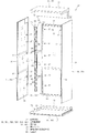
まず、図2に示す冷蔵庫11は、図1〜図6に示す断熱箱体12と、その断熱箱体12内を冷却するための図示しない冷凍サイクルとを備えている。
断熱箱体12は、図5および図6に示すように、外箱13と、内箱14と、外箱13と内箱14との間に設けられている断熱部材15とを有している。断熱箱体12は、前面が開口した箱状に構成され、内箱14の内部に収容空間、例えば貯蔵室、必要に応じてダクトが設けられる空間などを形成している。
First, the refrigerator 11 shown in FIG. 2 includes the heat insulation box 12 shown in FIGS. 1 to 6 and a refrigeration cycle (not shown) for cooling the inside of the heat insulation box 12.
As shown in FIGS. 5 and 6, the heat insulating box body 12 includes an outer box 13, an inner box 14, and a heat insulating member 15 provided between the outer box 13 and the inner box 14. . The heat insulation box 12 is formed in a box shape with an open front surface, and forms an accommodation space, for example, a storage room, a space in which a duct is provided as necessary, etc. inside the inner box 14.
外箱13は、スチール製であり、前面が開口した箱状に構成されている。外箱13は、図1および図3〜図6に示すように、当該外箱13を複数に分割してなる複数枚の外板からなる壁を組み合わせて構成されている。具体的には、外箱13は、板状の上面壁16と、平板状の底面壁17と、平板状の右面壁18と、平板状の左面壁19と、平板状の背面壁20とから構成されている。上面壁16は、前後方向で段差状をなし、前部が底面壁17と平行な平板状をなし、後部が前部よりも下側に位置して底面壁17と平行な平板状をなしている。右面壁18と左面壁19とは左右対称の形状である。上面壁16の後部上には、図3〜図5に示すように、機械室21が形成されている。機械室21には、上述した冷凍サイクルを構成する図示しない圧縮機などが設けられている。機械室21の床面には、図5に示すように、離間部211が形成されている。離間部211は、隣り合った断熱部材15間に隙間を設けることにより形成された開口である。この実施形態では、断熱箱体12の上面に位置する断熱部材15と背面に位置する断熱部材15とが離間して配置されることにより、離間部211が形成されている。また、断熱箱体12の後部の下部には冷蔵用、冷凍用、あるいは制御などに用いられる部品、凝縮器などを収容する部品収容室212が形成されている。また、部品収納室212の上面には、離間部213が形成されている。離間部213は、断熱箱体12の底面に位置する断熱部材15と背面に位置する断熱部材15とが離間して配置されることにより形成されている。
The outer box 13 is made of steel and has a box shape with an open front surface. As shown in FIGS. 1 and 3 to 6, the outer box 13 is configured by combining walls made of a plurality of outer plates obtained by dividing the outer box 13 into a plurality of parts. Specifically, the outer box 13 includes a plate-like top wall 16, a plate-like bottom wall 17, a plate-like right wall 18, a plate-like left wall 19, and a plate-like back wall 20. It is configured. The top wall 16 has a step shape in the front-rear direction, the front part is a flat plate shape parallel to the bottom wall 17, and the rear part is located below the front part and is a flat plate shape parallel to the bottom wall 17. Yes. The right surface wall 18 and the left surface wall 19 have a symmetrical shape. As shown in FIGS. 3 to 5, a machine room 21 is formed on the rear portion of the upper surface wall 16. The machine room 21 is provided with a compressor (not shown) that constitutes the refrigeration cycle described above. As shown in FIG. 5, a separation portion 211 is formed on the floor surface of the machine room 21. The separation portion 211 is an opening formed by providing a gap between adjacent heat insulating members 15. In this embodiment, the space | interval part 211 is formed by the heat insulation member 15 located in the upper surface of the heat insulation box 12, and the heat insulation member 15 located in a back surface spaced apart. In addition, a component storage chamber 212 for storing components used for refrigeration, freezing, or control, a condenser, and the like is formed in the lower portion of the rear portion of the heat insulation box 12. In addition, a separation portion 213 is formed on the upper surface of the component storage chamber 212. The separation portion 213 is formed by disposing the heat insulation member 15 located on the bottom surface of the heat insulation box 12 and the heat insulation member 15 located on the back surface.
内箱14は、樹脂製であり、前面が開口した箱状をなし、外箱13の内部に設けられている。内箱14は、図1および図3〜図6に示すように、当該内箱14を複数に分割してなる複数枚の内板からなる壁を組み合わせて構成されている。具体的には、内箱14は、板状の上面壁22と、平板状の底面壁23と、平板状の右面壁24と、平板状の左面壁25と、平板状の背面壁26とから構成されている。内箱14の上面壁22も、外箱13の上面壁16と同様に、前後方向で段差状をなし、前部が底面壁23と平行な平板状をなし、後部が前部よりも下側に位置して底面壁23と平行な平板状をなしている。右面壁24と左面壁25とは左右対称の形状である。
The inner box 14 is made of resin, has a box shape with an open front surface, and is provided inside the outer box 13. As shown in FIGS. 1 and 3 to 6, the inner box 14 is configured by combining walls made of a plurality of inner plates obtained by dividing the inner box 14 into a plurality of parts. Specifically, the inner box 14 includes a plate-like top wall 22, a plate-like bottom wall 23, a plate-like right wall 24, a plate-like left wall 25, and a plate-like back wall 26. It is configured. Similarly to the upper surface wall 16 of the outer box 13, the upper surface wall 22 of the inner box 14 has a step shape in the front-rear direction, the front part forms a flat plate shape parallel to the bottom wall 23, and the rear part is lower than the front part. It is located in a flat plate shape parallel to the bottom wall 23. The right side wall 24 and the left side wall 25 have a symmetrical shape.
内箱14の左面壁25および背面壁26のそれぞれには、図1および図11に示すように、内箱14の外面側から当該内箱14の内面側すなわち貯蔵室側に突出する支持部材27が複数個設けられている。なお、内箱14の右面壁24にも、図24に示すように、同様の支持部材27が設けられている。
As shown in FIGS. 1 and 11, each of the left wall 25 and the back wall 26 of the inner box 14 has a support member 27 protruding from the outer surface side of the inner box 14 toward the inner surface side of the inner box 14, that is, the storage chamber side. Are provided. As shown in FIG. 24, a similar support member 27 is also provided on the right side wall 24 of the inner box 14.
支持部材27は、例えば、樹脂製のブロックであり、図20および図21に示すように、基端部が断熱部材15に接着して固定され、他端部である先端部が、内箱14の壁、例えば図20および図21では左面壁25および背面壁26に形成した開口部28を貫通している。さらに、内箱14の右面壁24における背面壁26側の上下方向に並んで設けられている支持部材27、および内箱14の背面壁26における右面壁24側および左面壁25側の上下方向に並んで設けられている支持部材27の先端部側には、ねじ穴271が形成されている。なお、図示はしないが、内箱14の右面壁24における背面壁26側の上下方向に並んで設けられている支持部材27の突出している先端部にも、同様のねじ穴が形成されている。なお、支持部材27が、図20および図21に示すように、基端部に鍔部272を有する構成とし、鍔部272が断熱部材15と内箱14の外面とで挟持される構成としてもよい。支持部材27が鍔部272を有することにより、支持部材27が開口部28から貯蔵室側に落ちてしまうことを防止できる。また、支持部材27は、内箱14の壁とは別の部材ではなく、内箱14に一体に成形させてもよい。
The support member 27 is, for example, a resin block. As shown in FIGS. 20 and 21, the base end is bonded and fixed to the heat insulating member 15, and the tip that is the other end is the inner box 14. 20 and 21, for example, in FIG. 20 and FIG. Furthermore, the support member 27 provided side by side in the vertical direction on the back wall 26 side of the right side wall 24 of the inner box 14, and the vertical direction on the right side wall 24 side and the left side wall 25 side in the back wall 26 of the inner box 14. A screw hole 271 is formed on the tip end side of the support member 27 provided side by side. Although not shown, a similar screw hole is also formed at the projecting tip of the support member 27 provided in the vertical direction on the back wall 26 side of the right wall 24 of the inner box 14. . As shown in FIGS. 20 and 21, the support member 27 may have a configuration having a flange portion 272 at the base end portion, and the flange portion 272 may be sandwiched between the heat insulating member 15 and the outer surface of the inner box 14. Good. Since the support member 27 has the flange part 272, it can prevent that the support member 27 falls from the opening part 28 to the store room side. Further, the support member 27 may be formed integrally with the inner box 14 instead of a member different from the wall of the inner box 14.
図5および図6に示すように、外箱13の上面壁16と内箱14の上面壁22、外箱13の底面壁17と内箱14の底面壁23、外箱13の右面壁18と内箱14の右面壁24、外箱13の左面壁19と内箱14の左面壁25、外箱13の背面壁20と内箱14の背面壁26は、それぞれ断熱部材15を介して対向して設けられている。なお、図6に、外箱13の右面壁18と内箱14の右面壁24とが対向し、外箱13の左面壁19と内箱14の左面壁25とが対向し、外箱13の背面壁20と内箱14の背面壁26とが対向した状態を概略的に示す。
5 and 6, the top wall 16 of the outer box 13 and the top wall 22 of the inner box 14, the bottom wall 17 of the outer box 13, the bottom wall 23 of the inner box 14, and the right wall 18 of the outer box 13 The right side wall 24 of the inner box 14, the left side wall 19 of the outer box 13 and the left side wall 25 of the inner box 14, the back wall 20 of the outer box 13 and the back wall 26 of the inner box 14 are opposed to each other via the heat insulating member 15. Is provided. In FIG. 6, the right side wall 18 of the outer box 13 and the right side wall 24 of the inner box 14 face each other, the left side wall 19 of the outer box 13 and the left side wall 25 of the inner box 14 face each other. A state in which the back wall 20 and the back wall 26 of the inner box 14 face each other is schematically shown.
断熱部材15は、断熱性能に優れたもの、例えばウレタンなどの発泡断熱材やソフトテープなどよりも熱伝導率が低いものであり、具体的には、平板状の一般的な真空断熱パネルであり、芯材と、芯材を収容する外袋体とを備えている。芯材は、断熱性の高い材料、例えばグラスウールなどの無機繊維の積層体を、例えばポリエチレンなどの合成樹脂フィルムからなる図示しない内袋体に収容した後、矩形板状に圧縮硬化して形成したものである。芯材は、その他、例えば抄紙法、加熱圧縮法などで形成してもよい。外袋体は、ガスバリア性を有する袋であり、例えばポリエチレンテレフタレートのフィルム、高密度ポリエチレンのフィルム、アルミ蒸着フィルム、アルミ箔シートなどを適宜組み合わせ積層し袋状に形成したものである。そして、断熱部材15は、芯材を外袋体に収容した状態で当該外袋体内を減圧して、減圧を維持したまま外袋体の開口部を熱溶着などによって密閉することにより構成されている。
The heat insulating member 15 is superior in heat insulating performance, for example, has a lower thermal conductivity than a foamed heat insulating material such as urethane or soft tape, and is specifically a flat general vacuum heat insulating panel. And a core material and an outer bag body for housing the core material. The core material was formed by compressing and curing a highly heat-insulating material, for example, a laminate of inorganic fibers such as glass wool, into an inner bag (not shown) made of a synthetic resin film such as polyethylene, and then compressing and curing it into a rectangular plate shape. Is. In addition, the core material may be formed by, for example, a papermaking method, a heat compression method, or the like. The outer bag body is a bag having gas barrier properties, for example, a polyethylene terephthalate film, a high-density polyethylene film, an aluminum vapor-deposited film, an aluminum foil sheet, etc., which are appropriately combined and formed into a bag shape. And the heat insulation member 15 is comprised by sealing the opening part of an outer bag body by heat welding etc., decompressing the said outer bag body in the state which accommodated the core material in the outer bag body, and maintaining pressure reduction. Yes.
断熱部材15は、平板状の板厚方向の一面が内箱14の外面に接着され、かつ、一面とは反対側の他面が外箱13の内面に接着されている。すなわち、断熱箱体12の内部は、断熱部材15が外板および内板に当接して配置されることにより構成されている。図7に一例として、外箱13の左面壁19と、外箱13の左面壁19に対向して設けられている内箱14の左面壁25との間に断熱部材15が挟まれて設けられた構成を示す。この構成において、断熱部材15と外箱13の内面この場合左面壁19との間には、断熱部材15と左面壁19とを接着させる接着剤29が設けられている。さらに、断熱部材15と内箱14の外面この場合左面壁25との間にも、断熱部材15と左面壁25とを接着させる接着剤30が設けられている。接着剤29,30としては、液体状の接着剤、両面テープなどが用いられる。なお、上述した支持部材27は、この接着剤30によって断熱部材15に接着されている。また、支持部材27は、固定具51と係合することにより、外箱13および内箱14に当接した構成としてもよい。
One surface of the heat insulating member 15 in the plate thickness direction is bonded to the outer surface of the inner box 14, and the other surface opposite to the first surface is bonded to the inner surface of the outer box 13. That is, the inside of the heat insulating box 12 is configured by the heat insulating member 15 being disposed in contact with the outer plate and the inner plate. As an example in FIG. 7, a heat insulating member 15 is provided between a left side wall 19 of the outer box 13 and a left side wall 25 of the inner box 14 provided to face the left side wall 19 of the outer box 13. The configuration is shown. In this configuration, an adhesive 29 for bonding the heat insulating member 15 and the left wall 19 is provided between the heat insulating member 15 and the inner surface of the outer box 13, in this case, the left wall 19. Further, an adhesive 30 for bonding the heat insulating member 15 and the left wall 25 is also provided between the heat insulating member 15 and the outer surface of the inner box 14, in this case, the left wall 25. As the adhesives 29 and 30, a liquid adhesive, a double-sided tape, or the like is used. The support member 27 described above is bonded to the heat insulating member 15 by the adhesive 30. Further, the support member 27 may be configured to contact the outer box 13 and the inner box 14 by engaging with the fixture 51.
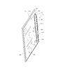
このように、外箱13の壁16〜20と、外箱13に対向して設けられた内箱14の壁22〜26と、その外箱13の壁16〜20と内箱14の壁22〜26との間に設けられた断熱部材15とを、接着剤29,30によって接着することにより、この外箱13の一の壁とその外箱13に対応する内箱14の一の壁と、それらの壁の間に設けられた断熱部材15とが一体となる。この一体となったものを断熱壁、この実施形態では分割断熱壁31と称する。なお、断熱壁および分割断熱壁31は、分割断熱パネルと称してもよい。すなわち、断熱箱体12は、複数の分割断熱壁31を組み合わせて箱状に構成されている。具体的には、図1に示すように、断熱箱体12は、当該断熱箱体12の上面壁を構成する上面用分割断熱壁311、当該断熱箱体12の床面壁を構成する床面用分割断熱壁312、当該断熱箱体12の右面壁である側壁を構成する右面用分割断熱壁313、当該断熱箱体12の左面壁である側壁を構成する左面用分割断熱壁314、当該断熱箱体12の背面壁を構成する背面用分割断熱壁315の5枚を組み合わせて構成されている。また、右面用分割断熱壁313および左面用分割断熱壁314は、左右対称の形状であり、対向して配置されている。
As described above, the walls 16 to 20 of the outer box 13, the walls 22 to 26 of the inner box 14 provided to face the outer box 13, the walls 16 to 20 of the outer box 13, and the wall 22 of the inner box 14. To the heat insulating member 15 provided between the inner box 14 and the inner box 14 corresponding to the outer box 13. The heat insulating member 15 provided between these walls is integrated. This integrated body is referred to as a heat insulating wall, in this embodiment a divided heat insulating wall 31. The heat insulating wall and the divided heat insulating wall 31 may be referred to as a divided heat insulating panel. That is, the heat insulation box 12 is configured in a box shape by combining a plurality of divided heat insulation walls 31. Specifically, as shown in FIG. 1, the heat insulation box 12 includes an upper surface divided heat insulation wall 311 constituting the upper surface wall of the heat insulation box 12 and a floor surface constituting the floor surface wall of the heat insulation box 12. The divided heat insulating wall 312, the right heat divided heat insulating wall 313 that constitutes the right side wall of the heat insulating box 12, the left heat divided heat insulating wall 314 that constitutes the left side wall of the heat insulating box 12, the heat insulating box The rear divided heat insulating wall 315 constituting the rear wall of the body 12 is combined to form five sheets. Moreover, the divided heat insulating wall for right surface 313 and the divided heat insulating wall for left surface 314 have a symmetrical shape and are arranged to face each other.
ここで、断熱箱体12の左右の壁を形成する右面用分割断熱壁313および左面用分割断熱壁314の前端部について図3、図4および図8を参照して説明する。なお、上述したように、右面用分割断熱壁313と左面用分割断熱壁314とは左右対称であるため、右面用分割断熱壁313の前端部について説明する。
Here, the front end portions of the right side divided heat insulating wall 313 and the left side divided heat insulating wall 314 that form the left and right walls of the heat insulating box 12 will be described with reference to FIGS. 3, 4, and 8. As described above, the right-side divided heat insulating wall 313 and the left-side divided heat insulating wall 314 are bilaterally symmetric, so the front end portion of the right-side divided heat insulating wall 313 will be described.
図3および図4に示すように、右面用分割断熱壁313の前端部の上下方向の中央部および下部付近の2箇所には、外箱13の右面壁18の前端部に折り曲げ部32が形成されている。2箇所の折り曲げ部32は同様の構成であるため、右面用分割断熱壁313の前端部の上下方向の中央部に設けられている折り曲げ部32について説明する。
As shown in FIG. 3 and FIG. 4, bent portions 32 are formed at the front end of the right wall 18 of the outer box 13 at two locations near the vertical center and lower part of the front end of the right split wall 313. Has been. Since the two bent portions 32 have the same configuration, the bent portion 32 provided at the center in the vertical direction of the front end portion of the right-side divided heat insulating wall 313 will be described.
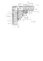
折り曲げ部32は、図8に示すように、右面壁18の前端部から左方向に折り曲がり、引き続き内箱14の右面壁24の前方において後方側に折り曲がり、さらに、断熱部材15側に折り曲がった形状である。すなわち、折り曲げ部32は、左右方向に延びる2つの平坦部321と、ほぼ360°に折り曲がっている湾曲部322とから構成され、上方から見てU字状をなしている。2つの平坦部321は、互いにほぼ対向しているとともに、断熱部材15の前方に位置している。また、湾曲部322は、内箱14の右面壁24の前方に位置し、折り曲げ部32の平坦部321の先端面が断熱箱体12の外面に位置しないように、折り曲げ部32の端部が後方側になるように折り曲がっている。さらに、折り曲げ部32の湾曲部322と内箱14の右面壁24の前端部との間には開口部33が形成されるとともに、折り曲げ部32と断熱部材15の前端部との間には、端部差込室34が形成された構成となっている。すなわち、開口部33は、端部差込室34の入口として機能するものであり、内箱14の右面壁24の前端部と外箱13の右面壁18の折り曲げ部32とが離間して形成されている。端部差込室34は、空間であり、右面壁18の折り曲げ部32と断熱部材15とが離間して形成されている。そして、その端部差込室34に、仕切り板441と仕切り補強板442とが収容される構成である。また、2つの平坦部321には、板厚方向に貫通する貫通孔35が形成されている。この開口部33、端部差込室34および貫通孔35については、後述する。
As shown in FIG. 8, the bent portion 32 is bent leftward from the front end portion of the right side wall 18, is subsequently bent to the rear side in front of the right side wall 24 of the inner box 14, and is further bent to the heat insulating member 15 side. It is a bent shape. That is, the bent portion 32 includes two flat portions 321 that extend in the left-right direction and a curved portion 322 that is bent at approximately 360 °, and has a U-shape when viewed from above. The two flat portions 321 are substantially opposed to each other and are positioned in front of the heat insulating member 15. The bent portion 322 is positioned in front of the right wall 24 of the inner box 14, and the end of the bent portion 32 is positioned so that the tip surface of the flat portion 321 of the bent portion 32 is not positioned on the outer surface of the heat insulating box 12. It is bent so as to be on the rear side. Further, an opening 33 is formed between the bent portion 322 of the bent portion 32 and the front end portion of the right surface wall 24 of the inner box 14, and between the bent portion 32 and the front end portion of the heat insulating member 15, An end insertion chamber 34 is formed. That is, the opening 33 functions as an inlet of the end insertion chamber 34, and the front end of the right wall 24 of the inner box 14 and the bent portion 32 of the right wall 18 of the outer box 13 are formed apart from each other. Has been. The end insertion chamber 34 is a space, and the bent portion 32 of the right wall 18 and the heat insulating member 15 are formed apart from each other. And the partition plate 441 and the partition reinforcement board 442 are accommodated in the edge part insertion chamber 34. As shown in FIG. Further, the two flat portions 321 are formed with through holes 35 penetrating in the plate thickness direction. The opening 33, the end insertion chamber 34, and the through hole 35 will be described later.
断熱箱体12の内箱14の内部である貯蔵室は、図3および図4に示すように、当該貯蔵室の中央部に設けられた第1の仕切り部材37と、第1の仕切り部材37の下方に設けられた第2の仕切り部材38とによって仕切られている。これにより、断熱箱体12の内部には、貯蔵室が複数に分割されて複数の部屋が形成されている。具体的には、内箱14と第1の仕切り部材37とで囲われて冷蔵室39が形成されている。また、内箱14と第1の仕切り部材37と第2の仕切り部材38とで囲われて野菜室40が形成されている。さらに、内箱14と第2の仕切り部材38とで囲われて内箱14の下部に空間が形成されている。この空間には、製氷室41と、第1の冷凍室42と、製氷室41の右隣に配置される第2の冷凍室43とが設けられる構成である。冷蔵室39の前面開口部には、図2に示すように、観音開き式の冷蔵室扉391が設けられ、野菜室40の前面開口部には引出し式の野菜室扉401が設けられている。また、製氷室41の前面開口部には引出し式の製氷室扉411が設けられ、第1の冷凍室42の前面開口部には引出し式の第1の冷凍室扉421が設けられ、第2の冷凍室43の前面開口部には引出し式の第2の冷凍室扉431が設けられている。
As shown in FIGS. 3 and 4, the storage chamber inside the inner box 14 of the heat insulating box 12 includes a first partition member 37 provided in the center of the storage chamber, and a first partition member 37. Is partitioned by a second partition member 38 provided below. Thereby, inside the heat insulation box 12, the storage room is divided into a plurality of rooms to form a plurality of rooms. Specifically, a refrigerator compartment 39 is formed by being surrounded by the inner box 14 and the first partition member 37. A vegetable compartment 40 is formed by being surrounded by the inner box 14, the first partition member 37, and the second partition member 38. Furthermore, a space is formed in the lower portion of the inner box 14 by being surrounded by the inner box 14 and the second partition member 38. In this space, an ice making room 41, a first freezing room 42, and a second freezing room 43 arranged on the right side of the ice making room 41 are provided. As shown in FIG. 2, a folding door type refrigerator compartment door 391 is provided at the front opening of the refrigerator compartment 39, and a drawer type vegetable compartment door 401 is provided at the front opening of the vegetable compartment 40. In addition, a drawer-type ice making room door 411 is provided at the front opening of the ice making room 41, and a drawer-type first freezing room door 421 is provided at the front opening of the first freezing room 42. A drawer-type second freezer compartment door 431 is provided at the front opening of the freezer compartment 43.
第1の仕切り部材37は、第2の仕切り部材38と同様の構成であるため、第1の仕切り部材37について図8を参照して説明する。また、第1の仕切り部材37は、左右対称の形状であるため、右側の構成について説明する。
Since the 1st partition member 37 is the structure similar to the 2nd partition member 38, the 1st partition member 37 is demonstrated with reference to FIG. Moreover, since the 1st partition member 37 is a left-right symmetric shape, the structure of the right side is demonstrated.
第1の仕切り部材37は、前仕切り部44と、面仕切り部45とから構成されている。
前仕切り部44は、貯蔵室の前面開口部に設けられ、当該貯蔵室の左右方向に延びる直方体状に構成されている。前仕切り部44は、仕切り板441と、仕切り補強板442と、仕切りカバー443と、仕切り断熱部材444とから構成されている。
The first partition member 37 includes a front partition portion 44 and a surface partition portion 45.
The front partition 44 is formed in a rectangular parallelepiped shape provided in the front opening of the storage chamber and extending in the left-right direction of the storage chamber. The front partition 44 includes a partition plate 441, a partition reinforcing plate 442, a partition cover 443, and a partition heat insulating member 444.
仕切り板441は、金属製であり、前仕切り部44の前面壁を構成する板部材であり、左右両端部がやや後方に折れ曲がっている。仕切り板441は、右端部が、右面用分割断熱壁313の前端部に形成されている開口部33を通って端部差込室34の内部に配置されている。前仕切り部44の右端部には、貫通孔445が3箇所形成されている。
The partition plate 441 is made of metal and is a plate member that constitutes the front wall of the front partition portion 44, and both left and right end portions are bent slightly rearward. A right end portion of the partition plate 441 is disposed inside the end insertion chamber 34 through an opening 33 formed at a front end portion of the right-side divided heat insulating wall 313. Three through holes 445 are formed at the right end of the front partition 44.
仕切り補強板442は、金属製であり、仕切り板441の引張強度が小さい場合などに設けられるものであり、上下方向の寸法が仕切り板441の上下方向の寸法と同様またはそれより短く調整され、左右方向の寸法が仕切り板441の左右方向の寸法よりも長く調整され、且つ、板厚が仕切り板441と同等またはそれ以上に調整された板部材であり、左右両端部がやや後方に折れ曲がっている。仕切り補強板442は、仕切り板441の背面に接して設けられている。
The partition reinforcing plate 442 is made of metal and provided when the tensile strength of the partition plate 441 is small, and the vertical dimension is adjusted to be the same as or shorter than the vertical dimension of the partition plate 441. It is a plate member in which the horizontal dimension is adjusted to be longer than the horizontal dimension of the partition plate 441, and the plate thickness is adjusted to be equal to or greater than that of the partition plate 441, and the left and right ends are bent slightly rearward. Yes. The partition reinforcing plate 442 is provided in contact with the back surface of the partition plate 441.
そして、仕切り板441の右端部が、右面用分割断熱壁313の前端部に形成されている開口部33を通って端部差込室34の内部に配置されている。これにより、仕切り板441の右端部は、仕切り補強板442の右端部と外箱13の右面壁18すなわち右面用分割断熱壁313の折り曲げ部32とで挟まれた構成となる。また、仕切り板441および仕切り補強板442の左右両端部が後方に折れ曲がった形状であり、この端部が端部差込室34に挿入される構成であるため、折り曲げ部32の前面を仕切り板441の前面と面一に構成することができる。
And the right end part of the partition plate 441 is arrange | positioned inside the edge part insertion chamber 34 through the opening part 33 formed in the front-end part of the division | segmentation heat insulation wall 313 for right surfaces. Thus, the right end portion of the partition plate 441 is sandwiched between the right end portion of the partition reinforcing plate 442 and the right side wall 18 of the outer box 13, that is, the bent portion 32 of the right side divided heat insulating wall 313. In addition, the left and right ends of the partition plate 441 and the partition reinforcing plate 442 are bent rearward, and the end portions are inserted into the end insertion chamber 34. Therefore, the front surface of the bent portion 32 is separated from the partition plate. 441 can be configured flush with the front surface of 441.
仕切り補強板442の右端部は、仕切り板441よりも右側に位置して断面L字状をなし、外箱13の右面壁18の右前部分の角の形状に対応して後方に折れ曲がっている。さらに、仕切り補強板442の右端部には、仕切り板441の3箇所の貫通孔445に対応する3箇所のねじ穴446が形成されている。3箇所のうちの最も右端部側に位置するねじ穴446は、外箱13の右面壁18の折り曲げ部32に形成した貫通孔35に通されるねじ46の軸部が設けられた構成となっている。また、仕切り補強板442の残り2箇所のねじ穴446にも、仕切り板441の貫通孔445に通されるねじ47の軸部が設けられた構成となっている。これにより、仕切り板441の右端部および仕切り補強板442の右端部は、右面用分割断熱壁313の折り曲げ部32に連結固定された構成となる。なお、上述したように、図示はしないが、仕切り板441の左端部および仕切り補強板442の左端部も、上述した右端部と同様な構成であり、外箱13の左面壁19すなわち左面用分割断熱壁314の図示しない折り曲げ部に連結固定された構成となっている。すなわち、仕切り板441は、右面用分割断熱壁313と左面用分割断熱壁314とを貯蔵室の前面開口部において連結固定する連結部材として機能し、折り曲げ部32は被連結部材として機能している。
The right end portion of the partition reinforcing plate 442 is located on the right side of the partition plate 441 and has an L-shaped cross section, and is bent backward corresponding to the corner shape of the right front portion of the right wall 18 of the outer box 13. Furthermore, three screw holes 446 corresponding to the three through holes 445 of the partition plate 441 are formed at the right end of the partition reinforcing plate 442. The screw hole 446 located on the rightmost end side among the three locations has a configuration in which a shaft portion of the screw 46 that is passed through the through hole 35 formed in the bent portion 32 of the right surface wall 18 of the outer box 13 is provided. ing. Further, the remaining two screw holes 446 of the partition reinforcing plate 442 are also provided with shaft portions of screws 47 that are passed through the through holes 445 of the partition plate 441. As a result, the right end portion of the partition plate 441 and the right end portion of the partition reinforcing plate 442 are connected and fixed to the bent portion 32 of the right-side split heat insulating wall 313. As described above, although not shown, the left end portion of the partition plate 441 and the left end portion of the partition reinforcing plate 442 have the same configuration as the right end portion described above, and the left wall 19 of the outer box 13, that is, the left-side partition. The structure is connected and fixed to a bent portion (not shown) of the heat insulating wall 314. That is, the partition plate 441 functions as a connecting member that connects and fixes the divided heat insulating wall 313 for the right surface and the divided heat insulating wall 314 for the left surface at the front opening of the storage chamber, and the bent portion 32 functions as a connected member. .
仕切りカバー443は、金属製であり、前面が開口した箱状をなし、仕切り板441とともに前仕切り部44の直方体の外周壁を形成するものである。そして、仕切りカバー443と仕切り板441とで形成される直方体の空間に、仕切り断熱部材444が設けられている。仕切りカバー443は、支持部材27によって支持されている。すなわち、仕切りカバー443は、下部に図示しない取付部を有し、この取付部がねじによって支持部材27に固定される構成である。
The partition cover 443 is made of metal, has a box shape with an open front surface, and forms a rectangular parallelepiped outer wall of the front partition portion 44 together with the partition plate 441. A partition heat insulating member 444 is provided in a rectangular parallelepiped space formed by the partition cover 443 and the partition plate 441. The partition cover 443 is supported by the support member 27. That is, the partition cover 443 has a mounting portion (not shown) in the lower portion, and the mounting portion is fixed to the support member 27 with screws.
仕切り断熱部材444は、発泡スチロールやウレタンなどの断熱部材からなり、直方体状に形成されている。
面仕切り部45は、図3および図4にも示すように、断熱性を有する樹脂製の矩形状の板部材であり、真空断熱パネルなどの板状の断熱部材の周囲を樹脂製の板で覆ったものである。面仕切り部45は、内箱14の支持部材27上に載置されて保持されているとともに、前端部が前仕切り部44の背面に接して設けられ、左右両端部が内箱14の右面壁24および左面壁25に接して設けられている。なお、第1の仕切り部材37の面仕切り部45の後端部は、内箱14の背面壁26に対して隙間を開けて設けられている。これにより、冷蔵室39と野菜室40とは連通した構成となっている。一方、第2の仕切り部材38の面仕切り部45の後端部は、内箱14の背面壁26に接して設けられている。これにより、野菜室40と製氷室41とは第2の仕切り部材38によって断熱されるとともに、野菜室40と第2の冷凍室43とも第2の仕切り部材38によって断熱された構成となっている。
The partition heat insulating member 444 is made of a heat insulating member such as polystyrene foam or urethane, and is formed in a rectangular parallelepiped shape.
As shown in FIGS. 3 and 4, the surface partition portion 45 is a resin-made rectangular plate member having heat insulation properties, and a plate made of resin around the plate-like heat insulation member such as a vacuum heat insulation panel. It's covered. The surface partition portion 45 is placed and held on the support member 27 of the inner box 14, the front end portion is provided in contact with the back surface of the front partition portion 44, and the left and right end portions are the right side wall of the inner box 14. 24 and the left wall 25 are provided in contact with each other. The rear end portion of the surface partition portion 45 of the first partition member 37 is provided with a gap with respect to the back wall 26 of the inner box 14. Thereby, the refrigerator compartment 39 and the vegetable compartment 40 have the structure which connected. On the other hand, the rear end portion of the surface partition portion 45 of the second partition member 38 is provided in contact with the back wall 26 of the inner box 14. Thus, the vegetable compartment 40 and the ice making chamber 41 are insulated from each other by the second partition member 38, and the vegetable compartment 40 and the second freezing compartment 43 are also insulated from each other by the second partition member 38. .
分割断熱壁31は、図1および図3〜図6に示すように、隣り合う他の分割断熱壁31に対して固定具51を介して連結固定されている。すなわち、内箱14は、複数に分割された壁22〜26において、一の壁に隣り合う他の壁によって形成されるコーナー部において、これらの2つの壁が固定具51を介して連結固定された構成となっている。
As shown in FIG. 1 and FIGS. 3 to 6, the divided heat insulating wall 31 is connected and fixed to another adjacent heat insulating wall 31 via a fixture 51. That is, in the inner box 14, in the walls 22 to 26 divided into a plurality of parts, these two walls are connected and fixed via the fixture 51 at a corner portion formed by another wall adjacent to the one wall. It becomes the composition.
固定具51は、内箱14にあって上面壁22と右面壁24とで形成されるコーナー部、上面壁22と左面壁25とで形成されるコーナー部、上面壁22と背面壁26とで形成されるコーナー部、底面壁23と右面壁24とで形成されるコーナー部、底面壁23と左面壁25とで形成されるコーナー部、底面壁23と背面壁26とで形成されるコーナー部に設けられている。言い換えると、固定具51は、隣り合って離間している2つの断熱部材15に対向する位置で固定されている。
The fixing tool 51 is provided in the inner box 14 and includes a corner portion formed by the top wall 22 and the right wall 24, a corner portion formed by the top wall 22 and the left wall 25, and the top wall 22 and the back wall 26. Corner portion formed, corner portion formed by bottom wall 23 and right wall 24, corner portion formed by bottom wall 23 and left wall 25, corner portion formed by bottom wall 23 and back wall 26 Is provided. In other words, the fixture 51 is fixed at a position facing the two heat insulating members 15 that are adjacent to each other and spaced apart.
また、内箱14の後部のコーナー部、例えば左面壁25と背面壁26とで形成される左奥側のコーナー部には、図6および図9に示すように、電線52が配置されている。電線52は、例えば図示しない制御手段たる制御装置と当該制御装置からの信号を受けて駆動する図示しない送風ファンなどの部品とをつなぐ電線、あるいは、制御装置と各種センサとをつなぐ電線であり、例えば、当該コーナー部に沿って延びている。電線52は、複数本の電線を束ねて構成されている。なお、図面では、複数本の電線が束ねられて断面が円形の状態となった電線52を示す。
Further, as shown in FIGS. 6 and 9, electric wires 52 are arranged in the rear corner portion of the inner box 14, for example, the left rear corner portion formed by the left wall 25 and the back wall 26. . The electric wire 52 is, for example, an electric wire that connects a control device (not shown) and a component such as a blower fan (not shown) that is driven by receiving a signal from the control device, or an electric wire that connects the control device and various sensors. For example, it extends along the corner portion. The electric wire 52 is configured by bundling a plurality of electric wires. In the drawing, an electric wire 52 in which a plurality of electric wires are bundled to have a circular cross section is shown.
さらに、内箱14の後部であって電線52が設けられているコーナー部とは異なるコーナー部、例えば左面壁25と背面壁26とで形成される右奥側のコーナー部には、図6および図22に示すように、配管53が配置されている。配管53は、具体的には、図示しない冷蔵用の蒸発器とコンプレッサとをつなぐサクションパイプおよび冷凍用の蒸発器とコンプレッサとをつなぐサクションパイプなどであり、例えば当該コーナー部に沿って延びている。配管53は、例えば、冷蔵に用いられる冷媒が通るものと、冷凍に用いられる冷媒が通るものとの2本設けられている。
Further, a corner portion different from the corner portion at the rear portion of the inner box 14 where the electric wires 52 are provided, for example, the corner portion on the right back side formed by the left wall 25 and the back wall 26 is shown in FIG. As shown in FIG. 22, a pipe 53 is arranged. Specifically, the pipe 53 is a suction pipe that connects a refrigeration evaporator and a compressor (not shown), a suction pipe that connects a refrigeration evaporator and a compressor, and the like, and extends along the corner portion, for example. . Two pipes 53 are provided, for example, one through which a refrigerant used for refrigeration passes and one through which a refrigerant used for freezing passes.
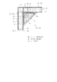
内箱14の各コーナー部に設けられている固定具51はよく似た構成であるため、以下、内箱14において左面壁25と背面壁26とで形成されるコーナー部に設けられている固定具511、および、右面壁24と背面壁26とで形成されるコーナー部に設けられている固定具512について説明する。なお、固定具512の説明においては、固定具511と共通する部分についての説明を省略する。また、上述の電線52および配管53の構成についても説明する。
Since the fixtures 51 provided at each corner portion of the inner box 14 have a similar configuration, hereinafter, the fixing provided at the corner portion formed by the left wall 25 and the back wall 26 in the inner box 14 will be described. The tool 511 and the fixture 512 provided at the corner formed by the right wall 24 and the back wall 26 will be described. In the description of the fixture 512, the description of the parts common to the fixture 511 is omitted. Moreover, the structure of the above-mentioned electric wire 52 and the piping 53 is also demonstrated.
まず、固定具511について図1、図9〜図21を参照して説明する。
固定具511は、図1、図9および図10に示すように、全体として断面直角三角形の柱状をなし、内箱14の左面壁25と背面壁26とで形成されるコーナー部に沿って上下方向に延びた形状をなしている。図9は、電線52が設けられているコーナー部付近を概略的に示すものである。図10は、コーナー部に固定具511を設けた後の当該コーナー部を示すものである。なお、図11は、当該コーナー部に固定具511が設けられる前の当該コーナー部を示している。
First, the fixture 511 will be described with reference to FIGS. 1 and 9 to 21.
As shown in FIGS. 1, 9 and 10, the fixture 511 has a columnar shape with a right-angled triangular section as a whole, and is vertically moved along a corner portion formed by the left wall 25 and the back wall 26 of the inner box 14. It has a shape extending in the direction. FIG. 9 schematically shows the vicinity of a corner portion where the electric wire 52 is provided. FIG. 10 shows the corner portion after the fixture 511 is provided at the corner portion. In addition, FIG. 11 has shown the said corner part before the fixing tool 511 is provided in the said corner part.
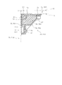
固定具511は、図12〜図14に示すように、断面直角三角形の筒状を構成する固定カバー54および補強部材55と、筒状の内部を構成するコーナー用断熱部材56とを有している。
As shown in FIGS. 12 to 14, the fixture 511 includes a fixing cover 54 and a reinforcing member 55 that form a cylindrical shape with a right-angled triangle cross section, and a corner heat insulating member 56 that forms a cylindrical interior. Yes.
固定カバー54は、樹脂製であり、上下方向に長い矩形の板部材であり、コーナー部に設けられている電線52の前側を覆うようにして配置されている。すなわち、冷蔵庫11の使用者側から電線52が見えないように固定カバー54が配置されている。固定カバー54の前面には、図14〜図21に示すように、ねじ57の軸部を貫通させるための貫通孔58が形成されている。固定カバー54の貫通孔58は、長手方向に直交する幅方向において両端部の複数個所に形成されている。この貫通孔58は、他方側の端部の貫通孔58が極力離れるように、他方側の端部に位置する貫通孔58と上下方向がずれて配置されている。すなわち、固定カバー54の貫通孔58は、例えば図13に示すように、固定カバー54の長手方向に沿ってジグザグ状に配置されている。
The fixed cover 54 is made of resin and is a rectangular plate member that is long in the vertical direction, and is disposed so as to cover the front side of the electric wire 52 provided in the corner portion. That is, the fixed cover 54 is disposed so that the electric wire 52 cannot be seen from the user side of the refrigerator 11. As shown in FIGS. 14 to 21, a through hole 58 for allowing the shaft portion of the screw 57 to penetrate is formed in the front surface of the fixed cover 54. The through holes 58 of the fixed cover 54 are formed at a plurality of locations at both ends in the width direction orthogonal to the longitudinal direction. The through-hole 58 is disposed so that the vertical direction is shifted from the through-hole 58 located at the other end so that the through-hole 58 at the other end is separated as much as possible. That is, the through holes 58 of the fixed cover 54 are arranged in a zigzag shape along the longitudinal direction of the fixed cover 54 as shown in FIG.
固定カバー54の貫通孔58のうち正面から見て左側に位置する貫通孔58の軸方向は、図15、図17、図19および図20に示すように、当該固定カバー54が内箱14のコーナー部に設けられたときに内箱14の左面壁25に直交する方向である。また、固定カバー54の貫通孔58のうち正面から見て右側に位置する貫通孔58の軸方向は、図15、図16、図18および図21に示すように、当該固定カバー54が内箱14のコーナー部に設けられたときに当該内箱14の背面壁26に直交する方向である。
As shown in FIGS. 15, 17, 19, and 20, the axial direction of the through hole 58 located on the left side of the through hole 58 of the fixed cover 54 is as follows. This is a direction orthogonal to the left wall 25 of the inner box 14 when provided at the corner. The axial direction of the through hole 58 located on the right side of the through hole 58 of the fixed cover 54 is as shown in FIGS. 15, 16, 18 and 21. 14 is a direction orthogonal to the back wall 26 of the inner box 14 when provided at the corners 14.
固定カバー54は、図1、図12および図13に示すように、固定具511が設けられるコーナー部の延びている方向の長さにおいて2個に分割されたパーツから構成されている。この構成により、固定カバー54の取扱いが容易になるとともに、ねじれなどの変形がしにくくなる。以下、固定カバー54のうち上側のパーツを上固定カバー541と称し、下側のパーツを下固定カバー542と称する。上固定カバー541は内箱14の冷蔵室39および野菜室40のコーナー部に配置され、下固定カバー542が内箱14の製氷室41および第1の冷凍室42のコーナー部に配置される構成である。固定カバー54のうち上固定カバー541と下固定カバー542とが連結する部分言い換えると分割部分は、図15に示すように左奥側のコーナー部側に突出し、後述する補強部材55に当接している。また、図10および図12〜図14に示すように、上固定カバー541の長手方向の中央部には端部側が開口した開口部59が形成され、下固定カバー542の長手方向の中央部にも端部側が開口した開口部60が形成されている。
As shown in FIGS. 1, 12, and 13, the fixed cover 54 is composed of parts divided into two parts in the length in the extending direction of the corner portion on which the fixture 511 is provided. With this configuration, the fixed cover 54 can be easily handled, and deformation such as twisting is difficult. Hereinafter, the upper part of the fixed cover 54 is referred to as an upper fixed cover 541, and the lower part is referred to as a lower fixed cover 542. The upper fixed cover 541 is disposed at the corner of the refrigerator compartment 39 and the vegetable compartment 40 of the inner box 14, and the lower fixed cover 542 is disposed at the corner of the ice making chamber 41 and the first freezer compartment 42 of the inner box 14. It is. The portion of the fixed cover 54 where the upper fixed cover 541 and the lower fixed cover 542 are connected. In other words, the divided portion protrudes to the left corner portion as shown in FIG. Yes. Further, as shown in FIGS. 10 and 12 to 14, an opening 59 having an opening on the end side is formed in the center portion in the longitudinal direction of the upper fixing cover 541, and the center portion in the longitudinal direction of the lower fixing cover 542 is formed. Also, an opening 60 having an opening on the end side is formed.
補強部材55は、固定具51の固定カバー54の強度を補強するものであり、樹脂製であり、図9、図12および図14に示すように、固定具511の断面二等辺三角形の残りの二辺を形成するカバー、具体的には直角の角を形成する断面L字状の板部材からなり、長手方向の長さが固定カバー54の長手方向の長さと同じに調整されている。補強部材55は、断面L字状をなす二辺のうちの一辺が内箱14の左面壁25すなわち左面用分割断熱壁314に対向して配置され、残りの一辺が内箱14の背面壁26すなわち背面用分割断熱壁315に対向して配置されている。
The reinforcing member 55 reinforces the strength of the fixing cover 54 of the fixing tool 51, and is made of resin. As shown in FIGS. 9, 12, and 14, the remaining isosceles cross section of the fixing tool 511 is left. A cover that forms two sides, specifically, a plate member having an L-shaped cross section that forms a right-angled corner, is adjusted in length in the longitudinal direction to be the same as the length in the longitudinal direction of the fixed cover 54. The reinforcing member 55 is arranged such that one of two sides having an L-shaped cross section faces the left side wall 25 of the inner box 14, that is, the left side divided heat insulating wall 314, and the other side is the rear wall 26 of the inner box 14. That is, it is arranged so as to face the rear split heat insulating wall 315.
この補強部材55の直角部分が内箱14のコーナー部に対応して配置される構成である。すなわち、補強部材55の断面L字状の直角部分が内箱14のコーナー部の角に最も近づいた状態になるようにして、固定具511が当該コーナー部に配置されている。そして、補強部材55の断面L字状の開いている側の開口部が固定カバー54によって覆われる構成である。言い換えると、補強部材55は、隣り合う分割断熱壁31の端部間すなわち隣り合う分割断熱壁31の離間している部分を横断して配置され、分割断熱壁31間の断熱効果の小さい所に配置された構成である。
The right angle portion of the reinforcing member 55 is arranged corresponding to the corner portion of the inner box 14. That is, the fixing member 511 is arranged at the corner portion so that the right-angle portion of the L-shaped cross section of the reinforcing member 55 is closest to the corner of the corner portion of the inner box 14. The opening on the open side of the reinforcing member 55 having an L-shaped cross section is covered with the fixed cover 54. In other words, the reinforcing member 55 is disposed between the end portions of the adjacent divided heat insulating walls 31, that is, across the spaced apart portions of the adjacent divided heat insulating walls 31, and in a place where the heat insulating effect between the divided heat insulating walls 31 is small. It is an arranged configuration.
補強部材55の長手方向に直交する幅方向の両端部には、複数のねじ穴61および複数の貫通孔62が形成されている。複数のねじ穴61および複数の貫通孔62は、固定カバー54の貫通孔58に対応して、補強部材55の長手方向に沿ってジグザグ状に配置されている。
A plurality of screw holes 61 and a plurality of through holes 62 are formed at both ends in the width direction orthogonal to the longitudinal direction of the reinforcing member 55. The plurality of screw holes 61 and the plurality of through holes 62 are arranged in a zigzag shape along the longitudinal direction of the reinforcing member 55 corresponding to the through holes 58 of the fixed cover 54.
補強部材55の貫通孔62は、固定カバー54側に膨出している膨出部63に形成されている。すなわち、膨出部63も補強部材55の長手方向に沿ってジグザグ状に配置されている。補強部材55の貫通孔62の軸方向は、固定カバー54が補強部材55に取り付けられたときに、固定カバー54の貫通孔58の軸方向に一致する構成である。補強部材55の貫通孔62には、ねじ57の軸部が貫通する構成である。
The through hole 62 of the reinforcing member 55 is formed in a bulging portion 63 that bulges toward the fixed cover 54. That is, the bulging portion 63 is also arranged in a zigzag shape along the longitudinal direction of the reinforcing member 55. The axial direction of the through hole 62 of the reinforcing member 55 is configured to coincide with the axial direction of the through hole 58 of the fixed cover 54 when the fixed cover 54 is attached to the reinforcing member 55. The shaft portion of the screw 57 passes through the through hole 62 of the reinforcing member 55.
補強部材55のねじ穴61は、図14、図15、図16および図19に示すように、固定カバー54側に突出した円筒状をなし、内部にねじ山が形成されたものである。補強部材55のねじ穴61は、固定カバー54が補強部材55に取り付けられたときに、固定カバー54の貫通孔58の軸方向に一致し、ねじ57と螺合する構成となっている。
As shown in FIGS. 14, 15, 16, and 19, the screw hole 61 of the reinforcing member 55 has a cylindrical shape protruding toward the fixed cover 54, and has a thread formed inside. The screw hole 61 of the reinforcing member 55 is configured to coincide with the axial direction of the through hole 58 of the fixed cover 54 and screw with the screw 57 when the fixed cover 54 is attached to the reinforcing member 55.
この補強部材55も、図14に示すように、固定具511が設けられるコーナー部の延びている方向の長さにおいて2個に分割されたパーツから構成されている。補強部材55の分割位置は、固定カバー54の分割位置と同じである。以下、補強部材55のうち上側のパーツを上補強部材551と称し、下側のパーツを下補強部材552と称する。この構成によって、上補強部材551も、冷蔵室39および野菜室40のコーナー部に配置され、下補強部材552が内箱14の製氷室41および第1の冷凍室42のコーナー部に配置される構成である。
As shown in FIG. 14, the reinforcing member 55 is also composed of parts divided into two parts in the length in the direction in which the corner portion where the fixture 511 is provided extends. The dividing position of the reinforcing member 55 is the same as the dividing position of the fixed cover 54. Hereinafter, the upper part of the reinforcing member 55 is referred to as an upper reinforcing member 551, and the lower part is referred to as a lower reinforcing member 552. With this configuration, the upper reinforcing member 551 is also disposed at the corners of the refrigerator compartment 39 and the vegetable compartment 40, and the lower reinforcing member 552 is disposed at the corner portions of the ice making chamber 41 and the first freezing chamber 42 of the inner box 14. It is a configuration.
コーナー用断熱部材56は、例えば図9に示すように、固定具511の固定カバー54に覆われるようにコーナー部に配置されたものであり、具体的には上述したように固定具511に囲われて設けられている。すなわち、コーナー用断熱部材56は、隣り合う分割断熱壁31の端部間である離間している部分を覆うように配置されている。コーナー用断熱部材56は、図14に示すように、発泡スチロールなどの断熱部材を三角柱に形成したものである。コーナー用断熱部材56の長手方向に直交する幅方向の両端部側には、複数の切欠き部64が形成されている。切欠き部64は、固定カバー54の貫通孔58、補強部材55のねじ穴61および貫通孔62に設けられるねじ57に干渉しないように、コーナー用断熱部材56の長手方向に沿ってジグザグ状に配置されている。このコーナー用断熱部材56も、固定具511が設けられるコーナー部の延びている方向の長さにおいて2個に分割されたパーツから構成されている。コーナー用断熱部材56の分割位置は、固定カバー54の分割位置と同じである。以下、コーナー用断熱部材56のうち上側のパーツを上コーナー用断熱部材561と称し、下側のパーツを下コーナー用断熱部材562と称する。この場合、上コーナー用断熱部材561は、上固定カバー541および上補強カバー551によって挟まれて設けられている。また、下コーナー用断熱部材562は、下固定カバー542および下補強カバー552によって挟まれて設けられている。この構成によって、上コーナー用断熱部材561も、冷蔵室39および野菜室40のコーナー部に配置され、下コーナー用断熱部材562が内箱14の製氷室41および第1の冷凍室42のコーナー部に配置される構成である。
For example, as shown in FIG. 9, the corner heat insulating member 56 is disposed at the corner portion so as to be covered by the fixing cover 54 of the fixing tool 511. Specifically, as described above, the corner insulating member 56 is surrounded by the fixing tool 511. It is provided. In other words, the corner heat insulating member 56 is disposed so as to cover the spaced apart portions between the ends of the adjacent divided heat insulating walls 31. As shown in FIG. 14, the corner heat insulating member 56 is formed by forming a heat insulating member such as foamed polystyrene into a triangular prism. A plurality of notches 64 are formed on both end sides in the width direction orthogonal to the longitudinal direction of the corner heat insulating member 56. The notch 64 is zigzag along the longitudinal direction of the corner heat insulating member 56 so as not to interfere with the screw 57 provided in the through hole 58 of the fixed cover 54, the screw hole 61 of the reinforcing member 55, and the through hole 62. Has been placed. The corner heat insulating member 56 is also composed of parts divided into two parts in the length in the extending direction of the corner portion where the fixture 511 is provided. The division position of the corner heat insulating member 56 is the same as the division position of the fixed cover 54. Hereinafter, the upper part of the corner heat insulating member 56 is referred to as an upper corner heat insulating member 561, and the lower part is referred to as a lower corner heat insulating member 562. In this case, the upper corner heat insulating member 561 is provided between the upper fixed cover 541 and the upper reinforcing cover 551. The lower corner heat insulating member 562 is provided between the lower fixed cover 542 and the lower reinforcing cover 552. With this configuration, the upper corner heat insulating member 561 is also arranged at the corner portions of the refrigerator compartment 39 and the vegetable compartment 40, and the lower corner heat insulating member 562 is the corner portion of the ice making chamber 41 and the first freezer compartment 42 of the inner box 14. It is the structure arrange | positioned.
上記構成によって、固定具511は、全体として、コーナー部に沿って延びる方向において2個に分割可能な構成となっている。なお、上コーナー用断熱部材561は、下コーナー用断熱部材562に対して離間して設けられている。すなわち、図15に示すように、固定カバー54の分割部分では、固定具511の分割部分の前面がコーナー部側に凹んだ形状になっている。
With the above-described configuration, the fixture 511 as a whole can be divided into two parts in the direction extending along the corner portion. The upper corner heat insulating member 561 is provided apart from the lower corner heat insulating member 562. That is, as shown in FIG. 15, in the divided portion of the fixed cover 54, the front surface of the divided portion of the fixture 511 has a shape recessed toward the corner portion side.
また、上コーナー用断熱部材561の長手方向の中央部には固定カバー541の開口部59に対応して端部側が開口した開口部65が形成され、下コーナー用断熱部材562の長手方向の中央部にも固定カバー541の開口部60に対応して端部側が開口した開口部66が形成されている。
Further, an opening 65 having an opening on the end side corresponding to the opening 59 of the fixed cover 541 is formed at the center of the upper corner heat insulating member 561 in the longitudinal direction, and the center of the lower corner heat insulating member 562 in the longitudinal direction is formed. An opening 66 having an opening on the end side corresponding to the opening 60 of the fixed cover 541 is also formed in this portion.
また、コーナー用断熱部材56の長手方向に直交する断面における直角部分、すなわち内箱14のコーナー部の角に近接する部位には、長手方向に延びる凹状の収容部67が形成されている。このコーナー用断熱部材56の収容部67には、上述した電線52が収容されている。すなわち、固定具511は、筒状の内部に電線52を収容した構成となっている。収容部67に収容されている電線52は、収容部67の内周面が保持部となって当該保持部によって所定の位置からずれないように保持されているとともに、図示しないフックなどの保持部などでも保持されている。すなわち、電線52と固定具511とは一体された構成となっている。電線52は、一部がコーナー用断熱部材56の開口部65を通って上固定カバー541の開口部59から貯蔵室側に出ており、また他の一部もコーナー用断熱部材56の開口部66を通って下固定カバー592の開口部60から貯蔵室側に出ており、さらに他の一部が固定具511の上端面から外側に出ており離間部211を通って機械室21に導かれている。すなわち、固定具511の開口部59,60は、固定具511の内部に収容されている電線52の一部を貯蔵室側に導くためのものである。なお、さらに、電線52の一部を固定具511の下端面から、離間部213を通って部分収容室212に導かれるようにしてもよい。
In addition, a concave accommodating portion 67 extending in the longitudinal direction is formed at a right-angled portion in a cross section orthogonal to the longitudinal direction of the corner heat insulating member 56, that is, a portion close to the corner of the corner portion of the inner box 14. The electric wire 52 described above is accommodated in the accommodating portion 67 of the corner heat insulating member 56. That is, the fixture 511 has a configuration in which the electric wire 52 is accommodated in a cylindrical shape. The electric wire 52 accommodated in the accommodating portion 67 is held by the inner peripheral surface of the accommodating portion 67 as a holding portion so as not to be displaced from a predetermined position by the holding portion, and a holding portion such as a hook (not shown). And so on. That is, the electric wire 52 and the fixture 511 are integrated. A part of the electric wire 52 passes through the opening 65 of the corner heat insulating member 56 and exits from the opening 59 of the upper fixed cover 541 to the storage chamber side, and the other part of the electric wire 52 opens to the corner heat insulating member 56. 66, exits from the opening 60 of the lower fixing cover 592 to the storage chamber side, and another part protrudes outward from the upper end surface of the fixture 511, leading to the machine chamber 21 through the separation portion 211. It is. That is, the openings 59 and 60 of the fixture 511 are for guiding a part of the electric wire 52 accommodated in the fixture 511 to the storage chamber side. Furthermore, a part of the electric wire 52 may be guided from the lower end surface of the fixture 511 to the partial housing chamber 212 through the separation portion 213.
電線52は、図13に示すように、固定カバー54の開口部59,60から貯蔵室側に出ている部分に接続部68を有している。また、電線52は、固定具511の上端面から外側に延びている先端部にも接続部68を有している。これらの接続部68は、樹脂製であり、他の電線の接続部と接続可能なプラグ状の構成となっている。他の電線は、例えば制御装置や送風ファンなどの部品に接続されている。
As shown in FIG. 13, the electric wire 52 has a connecting portion 68 at a portion protruding from the openings 59 and 60 of the fixed cover 54 to the storage chamber side. Further, the electric wire 52 also has a connection portion 68 at a tip portion extending outward from the upper end surface of the fixture 511. These connecting portions 68 are made of resin and have a plug-like configuration that can be connected to connecting portions of other electric wires. The other electric wires are connected to components such as a control device and a blower fan.
固定カバー54と補強部材55との間、具体的には固定カバー54の幅方向の端部と補強部材55の幅方向の端部との間には、図14および図16〜図19に示すように、第1のシール部材71が設けられている。第1のシール部材71は、固定カバー54および補強部材55の長手方向に沿って長く延びる部材であり、例えばソフトテープから構成されている。これにより、固定カバー54と補強部材55との間が第1のシール部材71によってシールされた構成となる。
14 and 16 to 19 are shown between the fixed cover 54 and the reinforcing member 55, specifically, between the widthwise end of the fixed cover 54 and the widthwise end of the reinforcing member 55. As described above, the first seal member 71 is provided. The first seal member 71 is a member that extends long along the longitudinal direction of the fixed cover 54 and the reinforcing member 55, and is made of, for example, a soft tape. As a result, the fixed cover 54 and the reinforcing member 55 are sealed by the first seal member 71.
補強部材55とこの補強部材55に近接する内箱14の壁、具体的には補強部材55と左面壁25すなわち左面用分割断熱壁314との間、および補強部材55と背面壁26すなわち背面用分割断熱壁315との間には、図14〜図19に示すように、第2のシール部材72が設けられている。第2のシール部材72は、固定カバー54および補強部材55の長手方向に沿って長く延びる部材であり、例えばソフトテープから構成されている。これにより、補強部材55とこの補強部材55に近接する分割断熱壁31との間が第2のシール部材72によってシールされた構成となる。
The reinforcing member 55 and the wall of the inner box 14 adjacent to the reinforcing member 55, specifically, between the reinforcing member 55 and the left side wall 25, that is, the left side divided heat insulating wall 314, and between the reinforcing member 55 and the rear side wall 26, that is, the rear side. As shown in FIGS. 14 to 19, a second seal member 72 is provided between the divided heat insulating walls 315. The second seal member 72 is a member that extends long along the longitudinal direction of the fixed cover 54 and the reinforcing member 55, and is made of, for example, a soft tape. As a result, the second sealing member 72 seals between the reinforcing member 55 and the divided heat insulating wall 31 adjacent to the reinforcing member 55.
図9に示すように、分割断熱壁31の端部、例えば左面用分割断熱壁314と背面用分割断熱壁315とが突き合されている部分には、第3のシール部材73が設けられている。第3のシール部材73は、固定カバー54および補強部材55の長手方向に平行に延びている部材であり、例えばソフトテープから構成されている。これにより、左面用分割断熱壁314と背面用分割断熱壁315との間が第3のシール部材73によってシールされた構成となる。なお、図20および図21では、第3のシール部材の図示を省略する。
As shown in FIG. 9, a third seal member 73 is provided at an end of the divided heat insulating wall 31, for example, a portion where the left heat insulating wall 314 and the rear heat insulating wall 315 are abutted. Yes. The third seal member 73 is a member extending in parallel to the longitudinal direction of the fixed cover 54 and the reinforcing member 55, and is made of, for example, a soft tape. Thereby, the space between the left divided heat insulating wall 314 and the rear divided heat insulating wall 315 is sealed by the third seal member 73. 20 and 21, the third seal member is not shown.
固定具511は、図14〜図19に示すように、固定カバー54と補強部材55とによってコーナー用断熱部材56を挟み、コーナー用断熱部材56の収容部67に電線52を収容し、固定カバー54の幅方向の端部と補強部材55の幅方向の端部とを合わせて構成されている。そして、このように固定カバー54を補強部材55に合わせた状態で、ねじ57の軸部を固定カバー54の貫通孔58に通して補強部材55のねじ穴61に螺合させることにより、固定カバー54が補強部材55に固定された構成となっている。また、固定カバー54が補強部材55に固定されることにより、コーナー用断熱部材56も固定具511の内部に固定された構成となり、電線52も固定具511の内部に固定された構成となっている。したがって、固定カバー54と、補強部材55と、コーナー用断熱部材56と、電線52とが一体化した構成となっている。
As shown in FIGS. 14 to 19, the fixing tool 511 sandwiches the corner heat insulating member 56 between the fixing cover 54 and the reinforcing member 55, and stores the electric wire 52 in the storage portion 67 of the corner heat insulating member 56. The end portion in the width direction of 54 and the end portion in the width direction of the reinforcing member 55 are combined. Then, in a state where the fixed cover 54 is aligned with the reinforcing member 55 in this way, the shaft portion of the screw 57 is passed through the through hole 58 of the fixed cover 54 and screwed into the screw hole 61 of the reinforcing member 55, thereby fixing the fixed cover. 54 is fixed to the reinforcing member 55. Further, by fixing the fixed cover 54 to the reinforcing member 55, the corner heat insulating member 56 is also fixed to the inside of the fixture 511, and the electric wire 52 is also fixed to the inside of the fixture 511. Yes. Therefore, the fixed cover 54, the reinforcing member 55, the corner heat insulating member 56, and the electric wire 52 are integrated.
なお、上固定カバー541と下固定カバー542との分割部分では、図15に示すように、1対のねじ57,57によって固定カバー54が補強部材55に固定されている。そして、固定具511の分割部分には、第2の仕切り部材38の後端部の左部が当接して配置される構成となっている。
Note that, in the divided portion of the upper fixed cover 541 and the lower fixed cover 542, the fixed cover 54 is fixed to the reinforcing member 55 by a pair of screws 57, 57 as shown in FIG. And the left part of the rear-end part of the 2nd partition member 38 contact | abuts and arrange | positions at the division | segmentation part of the fixing tool 511.
また、図20および図21に示すように、ねじ57を固定カバー54の貫通孔58および補強部材55の貫通孔62に通して内箱14の支持部材27のねじ穴に螺合させることにより、固定具511が内箱14のコーナー部に固定された構成となっている。
20 and 21, the screw 57 is threaded through the through hole 58 of the fixed cover 54 and the through hole 62 of the reinforcing member 55 and screwed into the screw hole of the support member 27 of the inner box 14, The fixture 511 is fixed to the corner portion of the inner box 14.
このとき、固定カバー54と補強部材55との間が第1のシール部材71によってシールされ、固定具51とこの固定具51に近接する分割断熱壁31との間が第2のシール部材72によってシールされ、左面用分割断熱壁314と背面用分割断熱壁315との間が第3のシール部材73によってシールされた構成となる。
At this time, the space between the fixed cover 54 and the reinforcing member 55 is sealed by the first seal member 71, and the space between the fixture 51 and the divided heat insulating wall 31 adjacent to the fixture 51 is sealed by the second seal member 72. The sealing is performed, and the space between the left-side divided heat insulating wall 314 and the rear-side divided heat insulating wall 315 is sealed by the third seal member 73.
さらに、左面用分割断熱壁314および背面用分割断熱壁315は、第2のシール部材72を介して補強部材55に対向した配置となる。これにより、隣り合う左面用分割断熱壁314および背面用分割断熱壁315が固定具511によって連結固定されるとともに、左面用分割断熱壁314と背面用分割断熱壁315とで形成される隣り合う分割断熱壁314,315の角度が、補強部材55の直角部分に対応して90°に保持される。すなわち、補強部材55は、左面用分割断熱壁314および背面用分割断熱壁315のそれぞれに対向して配置され、隣り合う壁すなわち分割断熱壁31の角度を90°に保持する角度保持部として機能している。
Further, the left split heat insulating wall 314 and the rear split heat insulating wall 315 are arranged to face the reinforcing member 55 with the second seal member 72 interposed therebetween. As a result, the adjacent divided heat insulation wall 314 for the left side and the divided heat insulation wall 315 for the back surface are connected and fixed by the fixture 511, and the adjacent division formed by the divided heat insulation wall 314 for the left surface and the divided heat insulation wall 315 for the back surface. The angle of the heat insulating walls 314 and 315 is maintained at 90 ° corresponding to the right angle portion of the reinforcing member 55. That is, the reinforcing member 55 is disposed so as to face the divided heat insulating wall 314 for the left surface and the divided heat insulating wall 315 for the rear surface, and functions as an angle holding portion that holds the adjacent wall, that is, the angle of the divided heat insulating wall 31 at 90 °. doing.
次に、固定具512について図22〜図31を参照して説明する。
固定具512は、図22および図23に示すように、全体として断面直角三角形の柱状をなし、内箱14の右面壁24と背面壁26とで形成されるコーナー部に沿って上下方向に延びた形状をなしている。図22は、配管53が設けられているコーナー部付近を概略的に示すものである。図23は、コーナー部に固定具512を設けた後の構成を示すものである。なお、図24は、当該コーナー部に固定具512を設ける前の構成を示している。
Next, the fixture 512 will be described with reference to FIGS.
As shown in FIGS. 22 and 23, the fixture 512 has a columnar shape having a right-angled triangular section as a whole, and extends in the vertical direction along a corner portion formed by the right wall 24 and the back wall 26 of the inner box 14. It has a different shape. FIG. 22 schematically shows the vicinity of the corner portion where the pipe 53 is provided. FIG. 23 shows a configuration after the fixture 512 is provided at the corner. Note that FIG. 24 shows a configuration before the fixture 512 is provided at the corner portion.
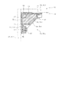
固定具512は、図25〜図27に示すように断面直角三角形の筒状を構成する固定カバー81および補強部材82と、筒状の内部を構成するコーナー用断熱部材83とを有している。
As shown in FIGS. 25 to 27, the fixture 512 includes a fixing cover 81 and a reinforcing member 82 that form a cylindrical shape having a right-angled triangle cross section, and a corner heat insulating member 83 that forms a cylindrical interior. .
固定カバー81は、固定カバー54とほぼ同様な構成であり、上下方向に長い矩形の板部材であり、コーナー部に設けられている配管53の前側を覆うようにして配置されている。すなわち、冷蔵庫11の使用者側から配管53が見えないように固定カバー81が配置されている。固定カバー81には、固定カバー54の貫通孔58と同様の貫通孔84が複数個所に形成されている。また、固定カバー81も、図27に示すように、固定具512が設けられるコーナー部の延びている方向の長さにおいて2個に分割されたパーツから構成され、固定カバー81のうち上側のパーツを構成する上固定カバー811と、下側のパーツを構成する下固定カバー812とから構成されている。上固定カバー811と下固定カバー812とが連結する部分すなわち分割部分は、図28に示すように右奥側のコーナー部側に突出した形成である。また、上固定カバー811の長手方向の中央部には、図27に示すように、外側に突出して延びる第1の突出部85を有し、この第1の突出部に開口部86が形成されている。また、図23および図25〜図27に示すように、下固定カバー812の長手方向の中央部にも、外側に突出して延びる第2の突出部87を有し、この第2の突出部87に開口部88が形成されている。
The fixed cover 81 has substantially the same structure as the fixed cover 54, is a rectangular plate member that is long in the vertical direction, and is arranged so as to cover the front side of the pipe 53 provided at the corner portion. That is, the fixed cover 81 is disposed so that the pipe 53 cannot be seen from the user side of the refrigerator 11. The fixed cover 81 is formed with a plurality of through holes 84 similar to the through holes 58 of the fixed cover 54. In addition, as shown in FIG. 27, the fixed cover 81 is also composed of parts divided into two parts in the length in the extending direction of the corner portion where the fixing tool 512 is provided, and the upper part of the fixed cover 81. The upper fixed cover 811 that constitutes the lower part and the lower fixed cover 812 that constitutes the lower part. A portion where the upper fixed cover 811 and the lower fixed cover 812 are connected, that is, a divided portion is formed to protrude toward the corner portion on the right rear side as shown in FIG. Further, as shown in FIG. 27, the upper fixed cover 811 has a first projecting portion 85 that projects outward and extends in the center in the longitudinal direction, and an opening 86 is formed in the first projecting portion. ing. Further, as shown in FIGS. 23 and 25 to 27, the lower fixed cover 812 has a second projecting portion 87 extending outwardly at the central portion in the longitudinal direction, and the second projecting portion 87. An opening 88 is formed in the opening.
補強部材82は、補強部材55とほぼ同様な構成であり、図27に示すように、固定具512の断面二等辺三角形の残りの二辺を形成する断面L字状の板部材である。この補強部材82の直角部分が内箱14のコーナー部に対応して配置される構成である。そして、補強部材82の断面L字状の開いている側の開口部を覆うようにして固定カバー81が設けられる構成である。
The reinforcing member 82 has substantially the same configuration as the reinforcing member 55, and is a plate member having an L-shaped cross section that forms the remaining two sides of the isosceles cross section of the fixture 512, as shown in FIG. The right angle portion of the reinforcing member 82 is arranged corresponding to the corner portion of the inner box 14. And it is the structure by which the fixed cover 81 is provided so that the opening part of the open side of the L-shaped cross section of the reinforcement member 82 may be covered.
補強部材55の長手方向に直交する幅方向の両端部には、複数のねじ穴89および複数の貫通孔90が形成されている。補強部材82のねじ穴89および貫通孔90も、補強部材55のねじ穴61および貫通孔62と同様の構成である。また、この補強部材82も、固定具512が設けられるコーナー部の延びている方向の長さにおいて2個に分割されたパーツから構成され、補強部材82のうち上側のパーツを構成する上補強部材821と、下側のパーツを構成する下補強部材822とから構成されている。また、上補強部材821は、当該上補強部材821の長手方向の中央部すなわち第1の突出部85に対応する位置に外側に突出して延びる第1の補強用突出部91を有している。第1の補強用突出部91は、第1の突出部85とともに筒状を形成するものである。さらに、下補強部材822も、当該下補強部材822の長手方向の中央部すなわち第2の突出部87に対応する位置に外側に突出して延びる第2の補強用突出部92を有している。第2の補強用突出部92も、第2の突出部87とともに筒状を形成するものである。
A plurality of screw holes 89 and a plurality of through holes 90 are formed at both ends in the width direction orthogonal to the longitudinal direction of the reinforcing member 55. The screw hole 89 and the through hole 90 of the reinforcing member 82 have the same configuration as the screw hole 61 and the through hole 62 of the reinforcing member 55. The reinforcing member 82 is also composed of two parts divided in the length in the extending direction of the corner portion where the fixture 512 is provided, and the upper reinforcing member constituting the upper part of the reinforcing member 82 821 and a lower reinforcing member 822 constituting the lower part. The upper reinforcing member 821 has a first reinforcing protrusion 91 that protrudes outward at a position corresponding to the central portion of the upper reinforcing member 821 in the longitudinal direction, that is, the first protrusion 85. The first reinforcing protrusion 91 forms a cylindrical shape together with the first protrusion 85. Further, the lower reinforcing member 822 also has a second reinforcing protrusion 92 that protrudes outward and extends at a position corresponding to the longitudinal center of the lower reinforcing member 822, that is, the second protrusion 87. The second reinforcing projection 92 also forms a cylinder with the second projection 87.
コーナー用断熱部材83は、コーナー用断熱部材56とほぼ同様な構成であり、固定具512の固定カバー81に覆われるようにコーナー部に配置されている。すなわち、コーナー用断熱部材83も、隣り合う分割断熱壁31の端部間である離間している部分を覆うように配置されている。コーナー用断熱部材83は、図27に示すように、発泡スチロールなどの断熱部材を三角柱に形成したものであり、幅方向の両端部側に複数の切欠き部93が形成されている。この切欠き部93は、コーナー用断熱部材56の切欠き部64と同様な構成である。また、このコーナー用断熱部材83も、固定具512が設けられるコーナー部の延びている方向の長さにおいて2個に分割されたパーツから構成され、コーナー用断熱部材83のうち上側のパーツを構成する上コーナー用断熱部材831と、下側のパーツを構成する下コーナー用断熱部材832とから構成されている。この場合、上コーナー用断熱部材831は、上固定カバー8111および上補強カバー821によって挟まれて設けられている。また、下コーナー用断熱部材832は、下固定カバー812および下補強カバー822によって挟まれて設けられている。
The corner heat insulating member 83 has substantially the same configuration as the corner heat insulating member 56, and is disposed at the corner portion so as to be covered by the fixing cover 81 of the fixing tool 512. That is, the corner heat insulating member 83 is also arranged so as to cover the spaced apart portions between the end portions of the adjacent divided heat insulating walls 31. As shown in FIG. 27, the corner heat insulating member 83 is formed by forming a heat insulating member such as foamed polystyrene into a triangular prism, and a plurality of notches 93 are formed on both ends in the width direction. The notch portion 93 has the same configuration as the notch portion 64 of the corner heat insulating member 56. The corner heat insulating member 83 is also composed of two parts divided in the length in the extending direction of the corner portion where the fixture 512 is provided, and constitutes the upper part of the corner heat insulating member 83. The upper corner heat insulating member 831 and the lower corner heat insulating member 832 constituting the lower part are configured. In this case, the upper corner heat insulating member 831 is provided between the upper fixed cover 8111 and the upper reinforcing cover 821. The lower corner heat insulating member 832 is provided between the lower fixed cover 812 and the lower reinforcing cover 822.
上記構成によって、固定具512は、全体として、コーナー部に沿って延びる方向において2個に分割可能な構成となっている。なお、上コーナー用断熱部材831は、下コーナー用断熱部材832に対して離間して設けられている。すなわち、図28に示すように、固定カバー81の分割部分では、当該固定カバー81のコーナー部側の面が補強部材82に接しており、固定具51の分割部分の前面がコーナー部側に凹んだ形状になっている。
With the above-described configuration, the fixture 512 as a whole can be divided into two parts in the direction extending along the corner portion. The upper corner heat insulating member 831 is provided so as to be separated from the lower corner heat insulating member 832. That is, as shown in FIG. 28, in the divided portion of the fixed cover 81, the surface on the corner portion side of the fixed cover 81 is in contact with the reinforcing member 82, and the front surface of the divided portion of the fixture 51 is recessed toward the corner portion side. It has a shape.
また、上コーナー用断熱部材831は、図27に示すように、当該上コーナー用断熱部材831の長手方向の中央部すなわち第1の突出部85に対応する位置に外側に突出して延びる第1の断熱用突出部94を有し、この第1の断熱用突出部94に開口部95が形成されている。第1の断熱用突出部94は、第1の補強用突出部91と第1の突出部85とで形成される筒状部分に収容される構成である。さらに、下コーナー用断熱部材832も、当該下コーナー用断熱部材832の長手方向の中央部すなわち第2の突出部87に対応する位置に外側に突出して延びる第2の断熱用突出部96を有し、この第2の断熱用突出部96に開口部97が形成されている。第2の断熱用突出部96は、第2の補強用突出部92と第2の突出部87とで形成される筒状部分に収容される構成である。
In addition, as shown in FIG. 27, the upper corner heat insulating member 831 has a first protrusion extending outwardly at a position corresponding to the central portion in the longitudinal direction of the upper corner heat insulating member 831, that is, the first protrusion 85. It has a heat insulating protrusion 94, and an opening 95 is formed in the first heat insulating protrusion 94. The first heat-insulating protrusion 94 is configured to be accommodated in a cylindrical portion formed by the first reinforcing protrusion 91 and the first protrusion 85. Further, the lower corner heat insulating member 832 also has a second heat insulating protrusion 96 extending outwardly at a position corresponding to the central portion in the longitudinal direction of the lower corner heat insulating member 832, that is, the second protrusion 87. An opening 97 is formed in the second heat-insulating protrusion 96. The second heat-insulating protrusion 96 is configured to be accommodated in a cylindrical portion formed by the second reinforcing protrusion 92 and the second protrusion 87.
また、コーナー用断熱部材83の長手方向に直交する断面における直角部分、すなわち内箱14のコーナー部の角に近接する部位には、長手方向に延びる凹状の収容部98が形成されている。このコーナー用断熱部材83の収容部98には、上述した配管53が収容されている。すなわち、固定具512は、筒状の内部に配管53を収容した構成となっている。収容部98に収容されている配管53は、収容部98の内周面が保持部となって当該保持部によって保持されているとともに、図示しないフックなどの保持部などでも保持されている。すなわち、配管53と固定具512とは一体された構成となっている。なお、収容部98に収容されている配管53は、コーナー部の部位によっては複数本収容されている。
In addition, a concave accommodating portion 98 extending in the longitudinal direction is formed at a right-angle portion in the cross section orthogonal to the longitudinal direction of the corner heat insulating member 83, that is, a portion close to the corner of the corner portion of the inner box 14. The above-described piping 53 is accommodated in the accommodating portion 98 of the corner heat insulating member 83. That is, the fixture 512 has a configuration in which the pipe 53 is accommodated in a cylindrical shape. The pipe 53 accommodated in the accommodating portion 98 is held by the holding portion with the inner peripheral surface of the accommodating portion 98 serving as a holding portion, and is also held by a holding portion such as a hook (not shown). That is, the piping 53 and the fixture 512 are integrated. Note that a plurality of pipes 53 accommodated in the accommodating portion 98 are accommodated depending on the portion of the corner portion.
配管53は、一部がコーナー用断熱部材83の開口部95を通って上固定カバー811の開口部86から貯蔵室側に出ており、他の一部がコーナー用断熱部材83の開口部97を通って下固定カバー812の開口部88から貯蔵室側に出ており、さらに他の一部が固定具512の上端面から外側に出ており離間部211を通って機械室21に導かれている。すなわち、固定具512の開口部86,88は、固定具512の内部に収容されている配管53の一部を貯蔵室側に導くためのものである。なお、さらに、配管53の一部を固定具512の下端面から、離間部213を通って部分収容室212に導かれるようにしてもよい。
A part of the piping 53 passes through the opening 95 of the corner heat insulating member 83 and exits from the opening 86 of the upper fixing cover 811 to the storage chamber side, and the other part of the piping 53 opens to the opening 97 of the corner heat insulating member 83. Through the opening 88 of the lower fixed cover 812 to the storage chamber side, and another part protrudes outward from the upper end surface of the fixture 512 and is guided to the machine chamber 21 through the separation portion 211. ing. That is, the openings 86 and 88 of the fixture 512 are for guiding a part of the pipe 53 accommodated in the fixture 512 to the storage chamber side. Furthermore, a part of the pipe 53 may be guided from the lower end surface of the fixture 512 to the partial storage chamber 212 through the separation portion 213.
配管53は、図26に示すように、固定カバー81の開口部86,88から貯蔵室側に出ている部分に溶着部99を有している。また、配管53は、固定具512の上端面から外側に延びている先端部にも溶着部99を有している。これらの溶着部99は、他の配管の溶着部と溶着可能な構成、例えば配管53の直径が他の配管よりも大きい構成となっている。他の配管は、冷蔵用の蒸発器、冷凍用の蒸発器、コンプレッサに接続されている。この実施形態では、上固定カバー811の開口部86から貯蔵室側に延びる配管53が冷蔵用の蒸発器に接続され、下固定カバー812の開口部88から貯蔵室側に延びる配管が冷凍用の蒸発器に接続され、固定具512の上端面から外側に延びる配管が機械室21に設けられているコンプレッサに接続されるように、配管53の溶着部99と他の配管の溶着部とが溶着される構成となっている。
As shown in FIG. 26, the pipe 53 has a welded portion 99 at a portion protruding from the openings 86 and 88 of the fixed cover 81 toward the storage chamber. Further, the pipe 53 also has a welded portion 99 at a tip portion that extends outward from the upper end surface of the fixture 512. These welded portions 99 are configured to be welded to welded portions of other pipes, for example, the pipe 53 has a larger diameter than the other pipes. The other pipes are connected to an evaporator for refrigeration, an evaporator for freezing, and a compressor. In this embodiment, the pipe 53 extending from the opening 86 of the upper fixed cover 811 toward the storage chamber is connected to the refrigeration evaporator, and the pipe extending from the opening 88 of the lower fixed cover 812 to the storage chamber is used for freezing. The welded part 99 of the pipe 53 and the welded part of the other pipe are welded so that the pipe connected to the evaporator and extending outward from the upper end surface of the fixture 512 is connected to the compressor provided in the machine chamber 21. It becomes the composition which is done.
固定カバー81と補強部材82との間、具体的には固定カバー81の幅方向の端部と補強部材82の幅方向の端部との間には、固定具511に設けた第1のシール部材71と同様の第1のシール部材101が設けられている。
Between the fixed cover 81 and the reinforcing member 82, specifically, between the end in the width direction of the fixed cover 81 and the end in the width direction of the reinforcing member 82, a first seal provided on the fixture 511. A first seal member 101 similar to the member 71 is provided.
補強部材82とこの補強部材82に近接する内箱14の壁、具体的には補強部材82と右面壁24すなわち右面用分割断熱壁313との間、補強部材82と背面壁26すなわち背面用分割断熱壁315との間には、図27〜図31に示すように、第2のシール部材72と同様の第2のシール部材102が設けられている。
The reinforcing member 82 and the wall of the inner box 14 adjacent to the reinforcing member 82, specifically, between the reinforcing member 82 and the right side wall 24, that is, the right side divided heat insulating wall 313, between the reinforcing member 82 and the rear side wall 26, that is, the rear side divided As shown in FIGS. 27 to 31, a second seal member 102 similar to the second seal member 72 is provided between the heat insulating wall 315.
また、図22に示すように、右面用分割断熱壁313と背面用分割断熱壁315とが突き合されている部分には、第3のシール部材72と同様の第3のシール部材103が設けられている。
In addition, as shown in FIG. 22, a third seal member 103 similar to the third seal member 72 is provided at a portion where the divided heat insulation wall 313 for the right surface and the divided heat insulation wall 315 for the back surface are abutted. It has been.
固定具512は、図26〜図31に示すように、固定カバー81と補強部材82とによってコーナー用断熱部材83を挟み、コーナー用断熱部材83の収容部98に配管53を収容し、固定カバー81の幅方向の端部と補強部材82の幅方向の端部とを合わせて構成されている。そして、このように固定カバー81を補強部材82に合わせた状態で、ねじ57の軸部を固定カバー81の貫通孔84に通して補強部材82のねじ穴89に螺合させることにより、固定カバー81が補強部材82に固定された構成となっている。また、固定カバー81が補強部材82に固定されることにより、コーナー用断熱部材83も固定具51の内部に固定された構成となり、配管53も固定具512の内部に固定された構成となっている。この上固定カバー811と下固定カバー812の分割部分にも、第2の仕切り部材38の後端部の右部が当接して配置され、この分割部分を覆う構成となっている。
As shown in FIGS. 26 to 31, the fixture 512 sandwiches the corner heat insulating member 83 between the fixing cover 81 and the reinforcing member 82, and accommodates the pipe 53 in the accommodating portion 98 of the corner heat insulating member 83. The end portion in the width direction of 81 and the end portion in the width direction of the reinforcing member 82 are combined. Then, in a state where the fixed cover 81 is aligned with the reinforcing member 82 in this way, the shaft portion of the screw 57 is passed through the through hole 84 of the fixed cover 81 and screwed into the screw hole 89 of the reinforcing member 82, thereby fixing the fixed cover. 81 is fixed to the reinforcing member 82. Further, by fixing the fixing cover 81 to the reinforcing member 82, the corner heat insulating member 83 is also fixed to the inside of the fixture 51, and the pipe 53 is also fixed to the inside of the fixture 512. Yes. The right portion of the rear end portion of the second partition member 38 is also placed in contact with the divided portion of the upper fixed cover 811 and the lower fixed cover 812, and the divided portion is covered.
なお、上固定カバー811と下固定カバー812との分割部分では、図28に示すように、1対のねじ57,57によって固定カバー81が補強部材82に固定されている。そして、固定具512の分割部分には、第2の仕切り部材38の後端部の右部が当接して配置される構成となっている。
Note that, in the divided portion of the upper fixed cover 811 and the lower fixed cover 812, the fixed cover 81 is fixed to the reinforcing member 82 by a pair of screws 57, 57 as shown in FIG. And the right part of the rear-end part of the 2nd partition member 38 contact | abuts and arrange | positions at the division | segmentation part of the fixing tool 512. As shown in FIG.
また、図示しないねじの軸部を、図30に示すように、固定カバー81の貫通孔84および補強部材82の貫通孔90に通して内箱14の図示しない支持部材のねじ穴に螺合させることにより、固定具512が内箱14のコーナー部に固定された構成となる。なお、図示はしないが、固定具512は、同様な構成によって背面壁26の支持部材にも固定されている。
Further, as shown in FIG. 30, the shaft portion of the screw (not shown) is threaded into the screw hole of the support member (not shown) of the inner box 14 through the through hole 84 of the fixed cover 81 and the through hole 90 of the reinforcing member 82. Thus, the fixture 512 is fixed to the corner portion of the inner box 14. Although not shown, the fixture 512 is also fixed to the support member of the back wall 26 with the same configuration.
このとき、固定カバー81と補強部材82との間が第1のシール部材101によってシールされ、固定具51とこの固定具51に近接する分割断熱壁31との間が第2のシール部材102によってシールされ、右面用分割断熱壁313と背面用分割断熱壁315との間が第3のシール部材103によってシールされる。
At this time, the space between the fixed cover 81 and the reinforcing member 82 is sealed by the first seal member 101, and the space between the fixture 51 and the divided heat insulating wall 31 adjacent to the fixture 51 is sealed by the second seal member 102. Sealed, and the space between the right divided heat insulating wall 313 and the rear divided heat insulating wall 315 is sealed by the third seal member 103.
また、補強部材82は、第2のシール部材102を介して右面用分割断熱壁313および背面用分割断熱壁315のそれぞれに対向した配置となる。これにより、隣り合う右面用分割断熱壁313および背面用分割断熱壁315が固定具512によって連結固定されるとともに、右面用分割断熱壁313と背面用分割断熱壁315とで形成される隣り合う壁の角度が、補強部材82の直角部分に対応して90°に保持される。すなわち、補強部材82も、隣り合う壁の角度を90°に保持する角度保持部として機能している。
Further, the reinforcing member 82 is disposed so as to oppose each of the right divided heat insulating wall 313 and the rear divided heat insulating wall 315 with the second seal member 102 interposed therebetween. As a result, the adjacent divided heat insulation wall 313 for the right surface and the divided heat insulation wall 315 for the back surface are connected and fixed by the fixture 512, and the adjacent wall formed by the divided heat insulation wall 313 for the right surface and the divided heat insulation wall 315 for the back surface. Is maintained at 90 ° corresponding to the right angle portion of the reinforcing member 82. That is, the reinforcing member 82 also functions as an angle holding portion that holds the angle between adjacent walls at 90 °.
次に、固定具512の固定カバー81の開口部88から貯蔵室側に導かれている配管53の一部について図32を参照して説明する。図32に示すように、内箱14の内部において第2の仕切り部材38の面仕切り部45と内箱14の右面壁24との間には、仕切り部用断熱部材105が設けられている。仕切り部用断熱部材105は、発泡スチロールなどからなる断熱部材であり、前後方向に延びるブロック状をなしている。仕切り部用断熱部材105には、内箱14側が開口した凹部106が形成されている。そして、凹部106の内部には、固定具512の開口部88から貯蔵室側に出た配管53の一部が設けられた構成となっている。すなわち、固定具512の開口部88から出ている配管53の一部は、第2の仕切り部材38の縁部の前後方向に沿って設けられた構成となっている。
Next, a part of the pipe 53 guided to the storage chamber side from the opening 88 of the fixing cover 81 of the fixing tool 512 will be described with reference to FIG. As shown in FIG. 32, a partition insulating member 105 is provided between the surface partition 45 of the second partition member 38 and the right wall 24 of the inner box 14 inside the inner box 14. The partition heat insulating member 105 is a heat insulating member made of foamed polystyrene or the like, and has a block shape extending in the front-rear direction. The partition heat insulating member 105 is formed with a recess 106 opened on the inner box 14 side. And inside the recessed part 106, it has the structure by which a part of piping 53 which came out to the storage chamber side from the opening part 88 of the fixing tool 512 was provided. That is, a part of the pipe 53 that protrudes from the opening 88 of the fixture 512 is configured along the front-rear direction of the edge of the second partition member 38.
この仕切り部用断熱部材105の上面、前面および左面は、第2の仕切り部材38の面仕切り部45から延びている部材によって覆われている。
なお、図示はしないが、内箱14の内部において第2の仕切り部材38の面仕切り部45と内箱14の左面壁25との間にも、上述の仕切り断熱部材などを設けて、固定具512の開口部60から出ている電線52の一部が、第2の仕切り部材38の縁部の前後方向に沿って設けられる構成としてもよい。
The upper surface, the front surface, and the left surface of the partition heat insulating member 105 are covered with a member extending from the surface partition portion 45 of the second partition member 38.
Although not shown, the above partition heat insulating member is provided between the surface partition portion 45 of the second partition member 38 and the left wall 25 of the inner box 14 inside the inner box 14 to fix the fixture. A part of the electric wire 52 coming out of the opening 60 of 512 may be provided along the front-rear direction of the edge of the second partition member 38.
上記した一実施形態による冷蔵庫の断熱箱体12の組立て手順を図1および図33を参照して説明する。
まず、図1に示す分割断熱壁31および固定具51をそれぞれ製作する。次に、図33に示すように、隣り合う2つの分割断熱壁31のうちの一方、例えば左面用分割断熱壁314に固定具511をねじ57により取り付ける。次に、左面用分割断熱壁314と固定具511とが一体となったものに、背面用分割断熱壁315を取り付ける。これにより、隣り合う分割断熱壁31は連結固定され、内箱14の右奥側のコーナー部が形成される。このとき、左面用分割断熱壁314と背面用分割断熱壁315とで形成される隣り合う壁の角度は、補強部材55の直角部分に対応して90°に保持される。内箱14の他のコーナー部も、分割断熱壁31と固定具51とを連結固定することにより形成される。これにより、隣り合う分割断熱壁31の角度が90°である内箱14が形成され、直方体の断熱箱体12が形成される。なお、隣り合う分割断熱壁31の角度を90°にするだけではなく、この場合、隣り合う分割断熱壁31の角度がほぼ90°に調整され、断熱箱体12の各角部がほぼ90°となっていればよい。
The assembly procedure of the heat insulation box 12 of the refrigerator according to the above-described embodiment will be described with reference to FIGS.
First, the division | segmentation heat insulation wall 31 and the fixing tool 51 which are shown in FIG. 1 are each manufactured. Next, as shown in FIG. 33, a fixture 511 is attached to one of the two adjacent divided heat insulation walls 31, for example, the left heat insulation wall 314 with screws 57. Next, the rear split heat insulating wall 315 is attached to the left split heat insulating wall 314 and the fixture 511 integrated. Thereby, the adjacent division | segmentation heat insulation wall 31 is connected and fixed, and the corner part of the inner right side of the inner case 14 is formed. At this time, the angle between the adjacent walls formed by the left divided heat insulating wall 314 and the rear divided heat insulating wall 315 is maintained at 90 ° corresponding to the right angle portion of the reinforcing member 55. The other corner portion of the inner box 14 is also formed by connecting and fixing the divided heat insulating wall 31 and the fixture 51. Thereby, the inner box 14 whose angle of the adjacent division | segmentation heat insulation wall 31 is 90 degrees is formed, and the rectangular parallelepiped heat insulation box 12 is formed. In addition, not only the angle of the adjacent divided heat insulating wall 31 is set to 90 °, but in this case, the angle of the adjacent divided heat insulating wall 31 is adjusted to approximately 90 °, and each corner portion of the heat insulating box 12 is approximately 90 °. It only has to be.
また、断熱箱体12の組立て時に、第1の仕切り部材37および第2の仕切り部材38を所定の位置に設けることにより、冷蔵室39、野菜室40、製氷室41、第1の冷凍室42および第2の冷凍室43が形成されるとともに、貯蔵室の前面開口部側において、右面用分割断熱壁313と左面用分割断熱壁314とが第1の仕切り部材37および第2の仕切り部材38によって連結固定される。
Further, when the heat insulating box 12 is assembled, the first partition member 37 and the second partition member 38 are provided at predetermined positions, so that the refrigerator room 39, the vegetable room 40, the ice making room 41, and the first freezer room 42 are provided. The second freezer compartment 43 is formed, and on the front opening side of the storage compartment, the right heat insulating wall 313 and the left heat insulating wall 314 are divided into the first partition member 37 and the second partition member 38. It is fixed by connecting.
上記構成によれば、次の効果を奏する。
隣り合う2つの分割断熱壁31が固定具51で連結固定されることによって、冷蔵庫11の断熱箱体12形成される。すなわち、分割断熱壁31を組み合わせ、固定具51でこれらの分割断熱壁31を組み合わせることによって冷蔵庫11を組み立てることができる。したがって、この実施形態によれば、従来のように予め立体的な内箱に断熱部材を設ける構成よりも、冷蔵庫11の組立て作業が容易となる。
According to the said structure, there exists the following effect.
Two adjacent heat insulation walls 31 are connected and fixed by a fixture 51, whereby the heat insulation box 12 of the refrigerator 11 is formed. That is, the refrigerator 11 can be assembled by combining the divided heat insulating walls 31 and combining the divided heat insulating walls 31 with the fixture 51. Therefore, according to this embodiment, the assembling work of the refrigerator 11 becomes easier than the conventional configuration in which the heat insulating member is provided in advance in the three-dimensional inner box.
固定具51の補強部材55,82が角度保持部として機能するため、隣り合う分割断熱壁31の角度が90°に保持される。これにより、内箱14を直方体に形成することができる。また、内箱14の角部が90°に保持される構成であることにより、分割断熱壁31の組み合わせが容易となる。
Since the reinforcing members 55 and 82 of the fixture 51 function as an angle holding portion, the angle of the adjacent divided heat insulating walls 31 is held at 90 °. Thereby, the inner box 14 can be formed in a rectangular parallelepiped. Moreover, the combination of the division | segmentation heat insulation wall 31 becomes easy because it is the structure by which the corner | angular part of the inner box 14 is hold | maintained at 90 degrees.
固定具51が隣り合って離間している2つの断熱部材15に対向する位置で固定されているので、断熱部材15を、固定具51を基準にして固定できる。したがって、隣り合う分割断熱壁31の角度を90°に保持しやすくできる。
Since the fixing tool 51 is fixed at a position facing the two heat insulating members 15 adjacent to each other, the heat insulating member 15 can be fixed with the fixing tool 51 as a reference. Therefore, it is possible to easily maintain the angle of the adjacent divided heat insulating walls 31 at 90 °.
貯蔵室の前面開口部側において、右面用分割断熱壁313と左面用分割断熱壁314とが第1の仕切り部材37および第2の仕切り部材38によって連結固定されているので、右面用分割断熱壁313の前面および左面用分割断熱壁314の前面が確実に固定される。これにより、内箱14の前面開口部が左右方向に開いてしまうことを防止できるとともに内箱14のねじれを防止することができ、内箱14および断熱箱体12を直方体に保つことができる。
On the front opening side of the storage room, the right split heat insulating wall 313 and the left split heat insulating wall 314 are connected and fixed by the first partition member 37 and the second partition member 38, so the right split heat insulating wall The front surface of 313 and the front surface of the left-side split heat insulating wall 314 are securely fixed. Thereby, the front opening of the inner box 14 can be prevented from opening in the left-right direction, and the inner box 14 can be prevented from being twisted, and the inner box 14 and the heat insulating box 12 can be kept in a rectangular parallelepiped.
内箱14のコーナー部に設けられる電線52および配管53が固定具51によって覆われた構成であるので、電線52や配管53に食品が当たってしまうことを防止することができるとともに、電線52および配管53を冷蔵庫11の使用者に見せなくすることができて貯蔵室の内部の意匠性を良好にすることができる。
Since the electric wire 52 and the pipe 53 provided at the corner portion of the inner box 14 are covered with the fixture 51, it is possible to prevent food from hitting the electric wire 52 and the pipe 53, and the electric wire 52 and The piping 53 can be hidden from the user of the refrigerator 11, and the design inside the storage room can be improved.
内箱14のコーナー部にコーナー用断熱部材56,83が設けられているので、コーナー部での断熱効果を高めることができる。また、コーナー用断熱部材56,83が固定具51によって覆われた構成であるので、上述と同様に、貯蔵室の内部の意匠性を良好にすることができる。
Since the corner heat insulating members 56 and 83 are provided in the corner portion of the inner box 14, the heat insulating effect at the corner portion can be enhanced. Further, since the corner heat insulating members 56 and 83 are covered with the fixture 51, the interior design of the storage room can be improved as described above.
コーナー用断熱部材56,83が隣り合う分割断熱壁31の離間している部分を覆うように配置されているので、分割断熱壁31による断熱効果の小さい部分の断熱効果を補うことができる。これにより、断熱箱体12全体の断熱効果を向上させることができる。
Since the corner heat insulating members 56 and 83 are arranged so as to cover the spaced apart portions of the adjacent divided heat insulating walls 31, the heat insulating effect of the portion having a small heat insulating effect by the divided heat insulating walls 31 can be supplemented. Thereby, the heat insulation effect of the heat insulation box 12 whole can be improved.
固定具51が筒状をなし、電線52、配管53およびコーナー用断熱部材56,83が当該固定具51の内部に収容された構成であるので、電線52、配管53およびコーナー用断熱部材56,83が冷蔵庫11の使用者から確実に見えにくくすることができ、貯蔵室の内部の意匠性をより一層良好にすることができる。
Since the fixing tool 51 has a cylindrical shape, and the electric wire 52, the pipe 53, and the corner heat insulating members 56, 83 are housed inside the fixing tool 51, the electric wire 52, the pipe 53, and the corner heat insulating member 56, 83 can be surely difficult to see from the user of the refrigerator 11, and the design of the interior of the storage room can be further improved.
固定具51が、断面L字状をなす補強部材55,82を有しているので、固定具51の変形、特にねじれや、折れ曲がりが生じてしまうことを極力防止することができる。また、補強部材55,82の前面すなわち断面L字状の開口部に固定カバー54,81が設けられる構成であるため、固定具51を筒状にすることができる。
Since the fixture 51 has the reinforcing members 55 and 82 having an L-shaped cross section, it is possible to prevent the fixture 51 from being deformed, in particular, twisted or bent as much as possible. In addition, since the fixing covers 54 and 81 are provided on the front surfaces of the reinforcing members 55 and 82, that is, the openings having an L-shaped cross section, the fixing tool 51 can be formed into a cylindrical shape.
電線52および配管53は、コーナー用断熱部材56,83の収容部67,98によって保持されているので、電線52および配管53が所定の位置からずれてしまうことを防止することができる。
Since the electric wires 52 and the pipes 53 are held by the accommodating portions 67 and 98 of the corner heat insulating members 56 and 83, the electric wires 52 and the pipes 53 can be prevented from being displaced from predetermined positions.
固定具51に開口部59,60が形成され、内箱14のコーナー部に設けられている電線52を貯蔵室側に導く構成とした。これにより、開口部59,60から貯蔵室側に導かれた電線52を固定具51の外側すなわち貯蔵室側にある電線に接続させることができる。特に、電線52が固定具51の開口部59,60から出た部分に他の電線と接続する接続部68を有しているので、固定具51の外側で電線52と他の電線との接続を容易に行うことができる。
Openings 59 and 60 are formed in the fixture 51, and the electric wire 52 provided at the corner portion of the inner box 14 is guided to the storage chamber side. Thereby, the electric wire 52 led to the storage chamber side from the openings 59 and 60 can be connected to the electric wire outside the fixture 51, that is, on the storage chamber side. In particular, since the electric wire 52 has a connecting portion 68 for connecting to the other electric wire at the portion of the fixing device 51 that protrudes from the openings 59 and 60, the electric wire 52 is connected to the other electric wire outside the fixing device 51. Can be easily performed.
また、固定具51に開口部86,88が形成され、内箱14のコーナー部に設けられている配管83を貯蔵室側に導く構成とした。これにより、開口部86,88から貯蔵室側に導かれた配管83を貯蔵室側にある配管に接続させることができる。特に、配管53が固定具51の開口部86,88から出た部分に他の配管と溶着する溶着部99を有しているので、固定具51の外側で配管53と他の配管との溶着を容易に行うことができる。
Moreover, the opening part 86,88 was formed in the fixing tool 51, and it was set as the structure which guides the piping 83 provided in the corner part of the inner box 14 to the storage chamber side. Thereby, the piping 83 led to the storage chamber side from the openings 86 and 88 can be connected to the piping on the storage chamber side. In particular, since the pipe 53 has a welded portion 99 that is welded to other pipes at the portions of the fixtures 51 that protrude from the openings 86 and 88, the pipe 53 is welded to the other pipes outside the fixture 51. Can be easily performed.
固定具51と電線52とが一体化され、また固定具51と配管53とが一体化された構成であるので、分割断熱壁31が固定具51で連結固定される際に、電線52および配管53も分割断熱壁31の所定のコーナー部に設けることができる。これにより、電線52および配管53の組み立て作業を簡素化することができる。
Since the fixture 51 and the electric wire 52 are integrated, and the fixture 51 and the pipe 53 are integrated, when the divided heat insulating wall 31 is connected and fixed by the fixture 51, the electric wire 52 and the pipe are connected. 53 can also be provided at a predetermined corner of the divided heat insulating wall 31. Thereby, the assembly work of the electric wire 52 and the piping 53 can be simplified.
内箱14の左奥側のコーナー部に電線52が設けられ、内箱14の右奥側のコーナー部に配管53が設けられていて、電線52が固定具511によって覆われ、配管53が固定具512によって覆われる構成としたので、電線52が配管53によって冷やされることを防止することができる。
An electric wire 52 is provided at a corner portion on the left back side of the inner box 14, and a pipe 53 is provided at a corner portion on the right rear side of the inner box 14. The electric wire 52 is covered with a fixture 511, and the pipe 53 is fixed. Since the structure is covered with the tool 512, the electric wire 52 can be prevented from being cooled by the pipe 53.
配管53の一部が、第2の仕切り部材38の縁部に沿って配置されているので、固定具51を大きくすることなく配管53を長くすることができる。これにより、配管53がサクションパイプである場合、貯蔵室の収納スペースを十分に確保しつつも、配管53の熱交換の効率を向上させることができる。
Since a part of the pipe 53 is arranged along the edge of the second partition member 38, the pipe 53 can be lengthened without increasing the size of the fixture 51. Thereby, when the piping 53 is a suction pipe, the efficiency of the heat exchange of the piping 53 can be improved while ensuring the storage space of a storage chamber enough.
固定カバー54と補強部材55との間、および固定カバー81と補強部材82との間に第1のシール部材71,101が設けられているので、固定具51の内部に冷気が流入してしまうことを防止することができる。これにより、固定具51の内部の部品、例えば電線52などに結露が生じてしまうことを防止できる。
Since the first seal members 71 and 101 are provided between the fixed cover 54 and the reinforcing member 55 and between the fixed cover 81 and the reinforcing member 82, cold air will flow into the fixture 51. This can be prevented. Thereby, it can prevent that dew condensation will arise in the components inside the fixing tool 51, for example, the electric wire 52. FIG.
分割断熱壁31と固定具51との間に第2のシール部材72,102が設けられているので、貯蔵室内の冷気が断熱箱体12の外側に漏れること防ぐことができるとともに、断熱箱体12の外側の暖かい空気が貯蔵室内に入ることを防ぐことができる。
Since the second sealing members 72 and 102 are provided between the divided heat insulating wall 31 and the fixture 51, it is possible to prevent the cool air in the storage chamber from leaking outside the heat insulating box 12, and the heat insulating box. Twelve outside warm air can be prevented from entering the storage chamber.
右面用分割断熱壁313と背面用分割断熱壁315との間、および左面用分割断熱壁314と背面用分割断熱壁315との間に第3のシール部材73,103が設けられているので、断熱箱体12の内部と外部とを十分に断熱することができ、当該断熱箱体12の内部を効率よく冷却することができる。
Since the third seal members 73 and 103 are provided between the right divided heat insulating wall 313 and the rear divided heat insulating wall 315, and between the left divided heat insulating wall 314 and the rear divided heat insulating wall 315, The inside and outside of the heat insulation box 12 can be sufficiently insulated, and the inside of the heat insulation box 12 can be efficiently cooled.
固定具51がコーナー部に沿って延びる方向において複数に分割されているので、固定具51の取扱いが容易になる。また、固定具51の分割部分に、第2の仕切り部材38が配置されているので、貯蔵室内の冷気が第2の仕切り部材38の分割部分から固定具51の内部に入ることを防ぐことができる。
Since the fixture 51 is divided into a plurality of parts in the direction extending along the corner portion, the fixture 51 can be easily handled. Further, since the second partition member 38 is disposed in the divided portion of the fixture 51, it is possible to prevent cold air in the storage chamber from entering the interior of the fixture 51 from the divided portion of the second partition member 38. it can.
分割断熱壁31が、外板からなる壁16〜20、内板かならなる壁22〜26および断熱部材15をなす真空断熱パネルから構成され、真空断熱パネルの一面が外板に接着され、真空断熱パネルの他面が内板に接着されているので、真空断熱パネルによる断熱効果が得られるとともに、分割断熱壁31を薄くすることができ、断熱箱体12の壁を薄くすることができる。また、上記構成によれば、従来、外箱と内箱との間に設けられていた電線および配管を、食品の収納の際に邪魔になりにくいコーナー部に設けることができる。
The divided heat insulating wall 31 is composed of walls 16 to 20 made of an outer plate, walls 22 to 26 made of an inner plate, and a vacuum heat insulating panel forming a heat insulating member 15, and one surface of the vacuum heat insulating panel is bonded to the outer plate to form a vacuum. Since the other surface of the heat insulating panel is bonded to the inner plate, the heat insulating effect by the vacuum heat insulating panel can be obtained, the divided heat insulating wall 31 can be thinned, and the wall of the heat insulating box 12 can be thinned. Moreover, according to the said structure, the electric wire and piping which were conventionally provided between the outer box and the inner box can be provided in the corner part which is hard to become obstructive at the time of storage of foodstuffs.
固定具51の上下方向から電線52あるいは配管53が出ており、電線52あるいは配管53の直上に離間部211が配置され、電線52あるいは配管53の直下に離間部213が配置されている。この離間部211の直上には機械室21が設けられ、離間部213の直下には部品収容室212が設けられている。したがって、電線52および配管53を所定の位置に容易に配置できるとともに、他の電線や配管に容易に接続することができる。
(第2の実施形態)
次に、第2の実施形態について、図34を参照して説明する。なお、第1の実施形態と同一の構成のものについては同一の符号を付し、その構成の説明を省略する。なお、この実施形態では、内箱14の左奥側のコーナー部について説明するが、他のコーナー部にも適用することができる。
The electric wire 52 or the pipe 53 protrudes from the vertical direction of the fixture 51, the separating portion 211 is disposed immediately above the electric wire 52 or the piping 53, and the separating portion 213 is disposed immediately below the electric wire 52 or the pipe 53. The machine room 21 is provided immediately above the separation part 211, and the component storage room 212 is provided immediately below the separation part 213. Therefore, the electric wire 52 and the pipe 53 can be easily arranged at predetermined positions, and can be easily connected to other electric wires and pipes.
(Second Embodiment)
Next, a second embodiment will be described with reference to FIG. In addition, the same code | symbol is attached | subjected about the thing of the same structure as 1st Embodiment, and description of the structure is abbreviate | omitted. In addition, although this embodiment demonstrates the corner part of the left inner side of the inner case 14, it is applicable also to another corner part.
第2の実施形態の固定具111は、補強部材を有さず、第1の実施形態の固定カバー54とほぼ同様な形状の板部材であり、内箱14のコーナー部に沿って延びた形状である。この実施形態では、隣り合う2つの分割断熱壁31は、固定具111に図示しないないねじによって固定されている。すなわち、隣り合う2つの分割断熱壁31は、固定具111によって連結固定された構成となっている。
The fixing device 111 of the second embodiment is a plate member having substantially the same shape as the fixing cover 54 of the first embodiment without having a reinforcing member, and has a shape extending along the corner portion of the inner box 14. It is. In this embodiment, two adjacent divided heat insulation walls 31 are fixed to the fixture 111 by screws (not shown). That is, the two adjacent heat insulation walls 31 are connected and fixed by the fixture 111.
固定具111の幅方向の両端部には、内箱14の近接する壁22〜26、具体的には左面壁25および背面壁26に対向して延びる延出部112,113が形成されている。すなわち、一方の延出部112は断熱部材15の前側に向かって延び、他方の延出部113は断熱箱体12の右方向に向かって延びている。ここで、延出部112の内箱14側の平面は、延出部113の内箱14側の面に対して、直交するように延びている。したがって、隣り合う左面用分割断熱壁314および背面用分割断熱壁315が固定具111によって連結固定されると、左面用分割断熱壁314と背面用分割断熱壁315とで形成される隣り合う壁の角度が90°となる。すなわち、延出部112,113は、角度保持部として機能するものである。
At both ends in the width direction of the fixture 111, extending portions 112 and 113 extending facing the adjacent walls 22 to 26 of the inner box 14, specifically, the left wall 25 and the back wall 26 are formed. . That is, one extension part 112 extends toward the front side of the heat insulating member 15, and the other extension part 113 extends toward the right side of the heat insulating box 12. Here, the plane on the inner box 14 side of the extending portion 112 extends so as to be orthogonal to the surface of the extending portion 113 on the inner box 14 side. Accordingly, when the adjacent divided heat insulation wall 314 for the left surface and the divided heat insulation wall 315 for the back surface are connected and fixed by the fixture 111, the adjacent wall formed by the divided heat insulation wall 314 for the left surface and the divided heat insulation wall 315 for the back surface The angle is 90 °. That is, the extending parts 112 and 113 function as angle holding parts.
延出部112,113と内箱14の近接する壁25,26との間には、第4のシール部材114が設けられている。第4のシール部材114は、第2のシール部材72,112と同様のものである。
A fourth seal member 114 is provided between the extending portions 112 and 113 and the adjacent walls 25 and 26 of the inner box 14. The fourth seal member 114 is the same as the second seal members 72 and 112.
また、内箱14のコーナー部と固定具111とで形成される三角柱状の空間には、第2のコーナー用断熱部材115が設けられている。すなわち、固定具111は、コーナー用断熱部材115を覆うようにして配置されている。第2のコーナー用断熱部材115は、発泡スチロールなどの断熱部材であり、三角柱状に形成されている。
A second corner heat insulating member 115 is provided in a triangular prism-shaped space formed by the corner portion of the inner box 14 and the fixture 111. That is, the fixture 111 is disposed so as to cover the heat insulating member 115 for corners. The second corner heat insulating member 115 is a heat insulating member such as polystyrene foam and is formed in a triangular prism shape.
第2のコーナー用断熱部材115における内箱14のコーナー部の角側に近接する部位には、長手方向に延びる凹状の収容部116が形成されている。この第2のコーナー用断熱部材115の収容部116の内部には、電線52が収容され、当該収容部116によって保持されている。すなわち、収容部116も、電線52を保持する保持部として機能するものでる。
A concave accommodating portion 116 extending in the longitudinal direction is formed in a portion of the second corner heat insulating member 115 adjacent to the corner of the corner portion of the inner box 14. The electric wire 52 is accommodated inside the accommodating portion 116 of the second corner heat insulating member 115 and is held by the accommodating portion 116. That is, the accommodating part 116 also functions as a holding part that holds the electric wire 52.
上記構成によれば、補強部材を有さない構成の固定具111を用いることによっても隣り合う2つの分割断熱壁31を連結固定させることができる。
延出部112,113を固定具111に設けたので、内箱14の隣り合う壁の角度は90°に保持される。これにより、内箱14および断熱箱体12を直方体に形成することができる。
According to the said structure, the adjacent two division | segmentation heat insulation wall 31 can be connected and fixed also by using the fixing tool 111 of a structure which does not have a reinforcement member.
Since the extending portions 112 and 113 are provided on the fixture 111, the angle between adjacent walls of the inner box 14 is maintained at 90 °. Thereby, the inner box 14 and the heat insulation box 12 can be formed in a rectangular parallelepiped.
延出部112,113と分割断熱壁31との間に第4のシール部材114が設けられているので、貯蔵室内の冷気が断熱箱体12の外側に漏れること防ぐことができるとともに、断熱箱体12の外側の暖かい空気が貯蔵室内に入ることを防ぐことができる。
Since the 4th sealing member 114 is provided between the extension parts 112 and 113 and the division | segmentation heat insulation wall 31, while being able to prevent the cool air in a storage chamber leaking outside the heat insulation box 12, it is a heat insulation box. Warm air outside the body 12 can be prevented from entering the storage chamber.
第2のコーナー用断熱部材115の収容部116内に、電線52が収容されているので、電線52が所定の位置からずれてしまうことを防止することができる。
(第3の実施形態)
次に、第3の実施形態について、図35を参照して説明する。なお、第1の実施形態と同一の構成のものについては同一の符号を付し、その構成の説明を省略する。なお、この実施形態では、内箱14の右奥側のコーナー部について説明するが、他のコーナー部にも適用することができる。
Since the electric wire 52 is accommodated in the accommodating part 116 of the 2nd corner heat insulation member 115, it can prevent that the electric wire 52 shifts | deviates from a predetermined position.
(Third embodiment)
Next, a third embodiment will be described with reference to FIG. In addition, the same code | symbol is attached | subjected about the thing of the same structure as 1st Embodiment, and description of the structure is abbreviate | omitted. In addition, although this embodiment demonstrates the corner part of the inner right side of the inner case 14, it is applicable also to another corner part.
第3の実施形態では、図35に示すように、断熱部材120が、第1の断熱部材121と、第2の断熱部材122とから構成されている。第1の断熱部材121は、真空断熱パネルであり、内箱14の壁22〜26の外面側に接着して配置されている。第2の断熱部材122は、第1の断熱部材121よりも熱伝導率が高いすなわち第1の断熱部材121よりも断熱性能が低いもの、例えばソフトテープ、あるいは発泡断熱材、特にはウレタンである。第2の断熱部材122は、外箱13と内箱14との間で形成される空間すなわち断熱部材120が収容される空間のうち第1の断熱部材121以外のところ配置されている。この実施形態では、第2の断熱部材122が、外箱13の壁16〜20の内面側であって第1の断熱部材121の外面側に設けられるとともに、断熱箱体12のコーナー部、すなわち第1の実施形態での第3のシール部材73に相当する箇所にも設けられている。この場合、第1の断熱部材121は、断熱部材120が収容される空間の全体積の50%以上、より好ましくは80%以上を占めている。また、第2の断熱部材122は、第1の断熱部材121の体積よりも小さい体積に設定されている。また、図35に示すように、第1の断熱部材121の板厚をT1とし、第2の断熱部材122の板厚をT2とし、配管53の外径をT3とすると、T1>T3>T2に設定されている。ここでいう板厚とは、外箱13と内箱14の断面方向の厚さである。また、発泡断熱材においては、固化後の厚さである。
In 3rd Embodiment, as shown in FIG. 35, the heat insulation member 120 is comprised from the 1st heat insulation member 121 and the 2nd heat insulation member 122. As shown in FIG. The first heat insulating member 121 is a vacuum heat insulating panel, and is disposed on the outer surface side of the walls 22 to 26 of the inner box 14. The second heat insulating member 122 is made of a material having higher thermal conductivity than the first heat insulating member 121, that is, a heat insulating performance lower than that of the first heat insulating member 121, for example, soft tape or foam heat insulating material, particularly urethane. . The second heat insulating member 122 is disposed at a place other than the first heat insulating member 121 in a space formed between the outer box 13 and the inner box 14, that is, a space in which the heat insulating member 120 is accommodated. In this embodiment, the second heat insulating member 122 is provided on the inner surface side of the walls 16 to 20 of the outer box 13 and on the outer surface side of the first heat insulating member 121, and at the corner of the heat insulating box body 12, that is, It is also provided at a location corresponding to the third seal member 73 in the first embodiment. In this case, the first heat insulating member 121 occupies 50% or more of the total volume of the space in which the heat insulating member 120 is accommodated, more preferably 80% or more. The second heat insulating member 122 is set to a volume smaller than the volume of the first heat insulating member 121. Further, as shown in FIG. 35, the thickness of the first insulating member 121 and T 1, when the thickness of the second insulating member 122 and T 2, the outer diameter of the pipe 53 and T 3, T 1 > T 3 > T 2 is set. The plate thickness here is the thickness of the outer box 13 and the inner box 14 in the cross-sectional direction. Moreover, in a foam heat insulating material, it is the thickness after solidification.
上記構成によれば、第1の断熱部材121および第2の断熱部材122の両方の断熱部材を用いた冷蔵庫を得ることができる。この場合、第2の断熱部材122よりも断熱効果の優れる第1の断熱部材121の体積を大きくした構成であるため、断熱箱体12の壁を薄くでき、収納スペースを十分に確保することができる。
According to the said structure, the refrigerator using the heat insulation member of both the 1st heat insulation member 121 and the 2nd heat insulation member 122 can be obtained. In this case, since the volume of the first heat insulating member 121, which has a heat insulating effect superior to that of the second heat insulating member 122, is increased, the wall of the heat insulating box 12 can be thinned and sufficient storage space can be secured. it can.
また、断熱箱体12の板厚を小さくしたい構成においては、配管53を断熱箱体12の内部に収容できないことがある。したがって、この実施形態では、配管53を貯蔵室の内部の後方、この場合内箱14の右奥側のコーナー部に収容し、第1の断熱部材121の体積を大きくすることにより、収納スペースを十分に確保でき、断熱箱体12の断熱効果を良好にすることができる。
Further, in a configuration in which it is desired to reduce the plate thickness of the heat insulating box 12, the pipe 53 may not be accommodated inside the heat insulating box 12. Therefore, in this embodiment, the piping 53 is accommodated in the rear of the interior of the storage chamber, in this case, in the corner portion on the right back side of the inner box 14, and the volume of the first heat insulating member 121 is increased, thereby reducing the storage space. It can be ensured sufficiently, and the heat insulating effect of the heat insulating box 12 can be improved.
第2の断熱部材122の板厚T2が配管53の外径T3よりも小さく、配管53が断熱箱体12の内部に収容できない構成において、配管53を収容空間例えば貯蔵室の内部に収容し、第1の断熱部材121の板厚T1を第2の断熱部材122の板厚T2よりも大きくすることにより、断熱箱体12の断熱効果を良好にすることができる。
Smaller than the outer diameter T 3 having a thickness of T 2 is the pipe 53 of the second heat insulating member 122, accommodated in a configuration in which the pipe 53 can not be accommodated in the interior of the insulating box body 12, inside the accommodation space for example storage chamber piping 53 And the heat insulation effect of the heat insulation box 12 can be made favorable by making board thickness T1 of the 1st heat insulation member 121 larger than board thickness T2 of the 2nd heat insulation member 122. FIG.
第1の断熱部材121として、真空断熱パネルを用いることにより、良好な断熱性が得られる。また、板厚が小さい真空断熱パネルでも断熱効果が良好であるため、断熱箱体12の壁を薄くでき、収納スペースを十分に確保することができる。
By using a vacuum heat insulating panel as the first heat insulating member 121, good heat insulating properties can be obtained. Moreover, since the heat insulation effect is good even in a vacuum heat insulation panel having a small plate thickness, the wall of the heat insulation box 12 can be made thin and a sufficient storage space can be secured.
第2の断熱部材122として、発泡断熱材、この場合ウレタンを用いることにより、第1の断熱部材121同士の間、第1の断熱部材121と外箱13との間、第1の断熱部材121と内箱14との間を埋めることができる。これにより、断熱箱体12全体の断熱効果を良好にすることができる。
By using a foam heat insulating material, in this case urethane, as the second heat insulating member 122, between the first heat insulating members 121, between the first heat insulating member 121 and the outer box 13, the first heat insulating member 121. And the inner box 14 can be filled. Thereby, the heat insulation effect of the heat insulation box 12 whole can be made favorable.
なお、上記では配管53の外径をT3として説明したが、内箱14の左奥側のコーナー部において、電線52すなわち複数の電線の束の外径をT3としてもよい。
(その他の実施形態)
内箱のコーナー部に電線および配管が設けられた構成を用いて説明したが、当該コーナー部にそれら以外の部品、例えばホースなどが設けられ、この部品を固定具で覆う構成としてもよい。
In the above description the outer diameter of the pipe 53 as T 3, at the corner portion of the left rear side of the inner box 14, the outer diameter of the wire 52 i.e. a bundle of a plurality of electric wires may be T 3.
(Other embodiments)
Although it demonstrated using the structure by which the electric wire and piping were provided in the corner part of the inner box, it is good also as a structure which covers other parts, for example, a hose etc. in those corner parts, and covers this part with a fixing tool.
仕切り部材が設けられないコーナー部や、コーナー部の長さが短い場合などにおいては、固定具を複数に分割しなくてもよい。
第1の実施形態の固定具において、固定カバーの幅方向の両端部に第2の実施形態の延出部を設けて、延出部と内箱との間を、第2のシール部材の代わりに第4のシール部材でシールする構成としてもよい。
In a corner portion where no partition member is provided, or when the length of the corner portion is short, the fixture may not be divided into a plurality of parts.
In the fixing device of the first embodiment, the extending portions of the second embodiment are provided at both ends in the width direction of the fixing cover, and the space between the extending portion and the inner box is replaced with the second sealing member. Alternatively, the fourth sealing member may be used for sealing.
配管の一部または電線の一部が第2の仕切り部材の縁部の左右方向に沿って配置されていてもよい。また、配管の一部および電線の一部が第1の仕切り部材の縁部の前後方向あるいは左右方向に沿って配置されていてもよい。
A part of the pipe or a part of the electric wire may be arranged along the left-right direction of the edge of the second partition member. Moreover, a part of piping and a part of electric wire may be arrange | positioned along the front-back direction or the left-right direction of the edge part of a 1st partition member.
面仕切り部に用いられる断熱部材として、真空断熱パネル、ウレタン、発泡スチロールなどを用いるとともに、これらの断熱部材を上下から樹脂製または金属製の板で挟む構成としてもよい。
As the heat insulating member used for the surface partitioning portion, a vacuum heat insulating panel, urethane, polystyrene foam or the like may be used, and these heat insulating members may be sandwiched between resin plates or metal plates from above and below.
仕切り補強板は、仕切り板が十分に強度を有する場合などにおいては、省略してもよい。
隣り合う2つの分割断熱壁は、上記の実施形態の連結固定に加えて、ねじなどによって連結固定してもよい。
The partition reinforcing plate may be omitted when the partition plate has sufficient strength.
Two adjacent heat insulating walls may be coupled and fixed by screws or the like in addition to the coupling and fixing of the above embodiment.
上記した断熱箱体の組立て手順は一例に過ぎず、例えば、背面用分割断熱壁に固定具を取り付けた後に、右面用分割断熱壁あるいは左面用分割断熱壁をこの固定具に取り付ける手順でもよい。
The above-described procedure for assembling the heat insulating box is merely an example. For example, a procedure may be used in which, after a fixture is attached to the rear divided heat insulation wall, the right heat divided heat insulation wall or the left heat divided heat insulation wall is attached to the fixture.
シール部材として、ソフトテープの代わりにシリコンシーラーなどを用いてもよい。
内箱の右奥側のコーナー部に、第2のコーナー用断熱部材を設け、第2のコーナー用断熱部材の収容部の内部に配管を収容する構成としてもよい。
A silicon sealer or the like may be used as the sealing member instead of the soft tape.
It is good also as a structure which provides a 2nd heat insulation member for corners in the corner part of the inner right side of an inner box, and accommodates piping inside the accommodating part of the heat insulation member for 2nd corners.
また、冷蔵庫は貯蔵室の内部にミストを噴出すミスト放出部を有していてもよい。このミストは、静電霧化により生成されたものであり、直径1〜1000nmであることが好ましい。この場合、隣り合う2つの分割断熱壁によって形成されるコーナー部に固定具が設けられることにより、隣り合う分割断熱壁との間からミストが庫外に放出されることを抑制することができる。
Moreover, the refrigerator may have a mist discharge part which ejects mist to the inside of a storage chamber. This mist is generated by electrostatic atomization and preferably has a diameter of 1 to 1000 nm. In this case, it is possible to suppress the mist from being released from the space between the adjacent divided heat insulation walls by providing the fixture at the corner portion formed by the two adjacent heat insulation walls.
固定具は、内箱の一の壁に一体に形成されていてもよい。
分割断熱壁は側面あるいは上面などから見て、L字状、U字状をなしていてもよい。すなわち、固定具は、板状の分割断熱壁同士を連結固定するのみではなく、板状以外の分割断熱壁同士、板状の分割断熱壁と板状以外の分割断熱壁とを連結固定するものとしてもよい。
The fixture may be integrally formed on one wall of the inner box.
The divided heat insulating wall may be L-shaped or U-shaped when viewed from the side or upper surface. That is, the fixture not only connects and fixes the plate-shaped divided heat insulating walls, but also connects and fixes the divided heat insulating walls other than the plate shape, and the plate-shaped divided heat insulating walls and the divided heat insulating walls other than the plate shape. It is good.
分割断熱壁の断熱部材すなわち真空断熱パネルは、内箱の壁に一体に設けられていなくてもよく、また、外箱の壁に一体に設けられていてもよい。
分割断熱壁の断熱部材は、外箱の一の壁または内箱の一の壁のどちらか一方に当接して設けられていればよい。
The heat insulating member of the divided heat insulating wall, that is, the vacuum heat insulating panel may not be provided integrally with the wall of the inner box, and may be provided integrally with the wall of the outer box.
The heat insulating member of the divided heat insulating wall may be provided in contact with either one wall of the outer box or one wall of the inner box.
内箱を複数に分割してなる壁を固定具によって連結固定して箱状の内箱を形成し、その内箱を外箱と断熱部材とが一体となったものに取り付けて断熱箱体を形成する構成でもよい。この場合、内箱を複数に分割してなる壁は、平板状に限らず、例えば上面から見てL字状であってもよい。
A wall formed by dividing the inner box into a plurality of parts is connected and fixed by a fixture to form a box-shaped inner box, and the inner box is attached to the outer box and the heat insulating member integrated to attach the heat insulating box body. The structure to form may be sufficient. In this case, the wall formed by dividing the inner box into a plurality of shapes is not limited to a flat plate shape, and may be, for example, an L shape when viewed from the upper surface.
以上のように、本実施形態の冷蔵庫は、断熱部材が断熱壁を複数組み合わせて箱状に構成され、断熱箱体にあって隣り合う2つの断熱壁によって形成されるコーナー部に設けられ2つの断熱壁を連結固定する固定具を備えている。よって、断熱壁を組み合わせ固定具でこれらの断熱壁を組み合わせることによって冷蔵庫を組み立てることができ、従来のように予め立体的な内箱に断熱部材を設ける構成よりも、冷蔵庫の組立て作業が容易となる。
As described above, the refrigerator according to the present embodiment is configured in a box shape by combining a plurality of heat insulating members with a heat insulating wall, and is provided in a corner portion formed by two adjacent heat insulating walls in a heat insulating box body. A fixture for connecting and fixing the heat insulating walls is provided. Therefore, it is possible to assemble a refrigerator by combining these heat insulating walls with a combination fixing tool, and it is easier to assemble the refrigerator than a conventional structure in which a heat insulating member is provided in a three-dimensional inner box in advance. Become.
本発明のいくつかの実施形態を説明したが、これらの実施形態は、例として提示したものであり、発明の範囲を限定することは意図していない。これら新規な実施形態は、その他の様々な形態で実施されることが可能であり、発明の要旨を逸脱しない範囲で、種々の省略、置き換え、変更を行うことができる。これら実施形態やその変形は、発明の範囲や要旨に含まれるとともに、特許請求の範囲に記載された発明とその均等の範囲に含まれる。
Although several embodiments of the present invention have been described, these embodiments are presented by way of example and are not intended to limit the scope of the invention. These novel embodiments can be implemented in various other forms, and various omissions, replacements, and changes can be made without departing from the scope of the invention. These embodiments and modifications thereof are included in the scope and gist of the invention, and are included in the invention described in the claims and the equivalents thereof.