JP6252121B2 - Discharge lamp lighting device, discharge lamp lighting method, and projector - Google Patents
Discharge lamp lighting device, discharge lamp lighting method, and projector Download PDFInfo
- Publication number
- JP6252121B2 JP6252121B2 JP2013234709A JP2013234709A JP6252121B2 JP 6252121 B2 JP6252121 B2 JP 6252121B2 JP 2013234709 A JP2013234709 A JP 2013234709A JP 2013234709 A JP2013234709 A JP 2013234709A JP 6252121 B2 JP6252121 B2 JP 6252121B2
- Authority
- JP
- Japan
- Prior art keywords
- discharge lamp
- overshoot
- drive
- undershoot
- current
- Prior art date
- Legal status (The legal status is an assumption and is not a legal conclusion. Google has not performed a legal analysis and makes no representation as to the accuracy of the status listed.)
- Active
Links
Images


Classifications
-
- H—ELECTRICITY
- H05—ELECTRIC TECHNIQUES NOT OTHERWISE PROVIDED FOR
- H05B—ELECTRIC HEATING; ELECTRIC LIGHT SOURCES NOT OTHERWISE PROVIDED FOR; CIRCUIT ARRANGEMENTS FOR ELECTRIC LIGHT SOURCES, IN GENERAL
- H05B41/00—Circuit arrangements or apparatus for igniting or operating discharge lamps
- H05B41/14—Circuit arrangements
- H05B41/26—Circuit arrangements in which the lamp is fed by power derived from dc by means of a converter, e.g. by high-voltage dc
- H05B41/28—Circuit arrangements in which the lamp is fed by power derived from dc by means of a converter, e.g. by high-voltage dc using static converters
- H05B41/288—Circuit arrangements in which the lamp is fed by power derived from dc by means of a converter, e.g. by high-voltage dc using static converters with semiconductor devices and specially adapted for lamps without preheating electrodes, e.g. for high-intensity discharge lamps, high-pressure mercury or sodium lamps or low-pressure sodium lamps
- H05B41/292—Arrangements for protecting lamps or circuits against abnormal operating conditions
- H05B41/2928—Arrangements for protecting lamps or circuits against abnormal operating conditions for protecting the lamp against abnormal operating conditions
-
- H—ELECTRICITY
- H05—ELECTRIC TECHNIQUES NOT OTHERWISE PROVIDED FOR
- H05B—ELECTRIC HEATING; ELECTRIC LIGHT SOURCES NOT OTHERWISE PROVIDED FOR; CIRCUIT ARRANGEMENTS FOR ELECTRIC LIGHT SOURCES, IN GENERAL
- H05B41/00—Circuit arrangements or apparatus for igniting or operating discharge lamps
- H05B41/14—Circuit arrangements
- H05B41/26—Circuit arrangements in which the lamp is fed by power derived from dc by means of a converter, e.g. by high-voltage dc
- H05B41/28—Circuit arrangements in which the lamp is fed by power derived from dc by means of a converter, e.g. by high-voltage dc using static converters
- H05B41/288—Circuit arrangements in which the lamp is fed by power derived from dc by means of a converter, e.g. by high-voltage dc using static converters with semiconductor devices and specially adapted for lamps without preheating electrodes, e.g. for high-intensity discharge lamps, high-pressure mercury or sodium lamps or low-pressure sodium lamps
- H05B41/2881—Load circuits; Control thereof
- H05B41/2882—Load circuits; Control thereof the control resulting from an action on the static converter
Landscapes
- Circuit Arrangements For Discharge Lamps (AREA)
Description
本発明は、放電ランプ点灯装置、放電ランプ点灯方法、及びプロジェクターに関する。 The present invention relates to a discharge lamp lighting device, a discharge lamp lighting method, and a projector.
従来より、プロジェクター用の光源として、例えば、超高圧水銀ランプや、メタルハライドランプ、キセノンランプ等の放電ランプ(放電灯)が使用されている。 Conventionally, discharge lamps (discharge lamps) such as ultra-high pressure mercury lamps, metal halide lamps, and xenon lamps have been used as light sources for projectors.
ところで、このような放電ランプの点灯を制御する放電ランプ点灯装置では、放電ランプが点灯している時の駆動電流の波形にオーバーシュート及びアンダーシュートが発生することがある。 By the way, in such a discharge lamp lighting device that controls lighting of the discharge lamp, overshoot and undershoot may occur in the waveform of the drive current when the discharge lamp is lit.
オーバーシュート及びアンダーシュートは、放電ランプ点灯装置が備える回路構成等の原因により、放電ランプの電極間に一時的に想定以上の電流が流れる現象であり、放電ランプに供給される駆動電流の極性を切り替える度に、駆動電流の波形(矩形波)の立上り部分と立下り部分において、その波形が定常値となる基線を超過する現象のことを言う。 Overshoot and undershoot are phenomena in which a current exceeding the expected value temporarily flows between the electrodes of the discharge lamp due to a circuit configuration provided in the discharge lamp lighting device, and the polarity of the drive current supplied to the discharge lamp is changed. It means a phenomenon in which the waveform exceeds the baseline where the waveform becomes a steady value at the rising and falling portions of the waveform (rectangular wave) of the drive current each time switching is performed.
オーバーシュート及びアンダーシュートが発生すると、放電ランプの照度変化や、放電ランプの電極へのダメージ等を引き起こす。具体的に、オーバーシュート及びアンダーシュートの発生により、放電ランプの電極が過熱されると、電極を形成するタングステンが蒸散を引き起こし、放電ランプに黒化が発生する恐れがある。また、オーバーシュート及びアンダーシュートの発生により、放電ランプの電極に振動が加わると、電極コイルの破壊等を引き起こすこともある。 When overshoot and undershoot occur, the illuminance change of the discharge lamp, damage to the electrode of the discharge lamp, and the like are caused. Specifically, when the discharge lamp electrode is overheated due to the occurrence of overshoot and undershoot, tungsten forming the electrode may cause evaporation and blackening of the discharge lamp may occur. Further, when vibration is applied to the electrode of the discharge lamp due to the occurrence of overshoot and undershoot, the electrode coil may be destroyed.
このようなオーバーシュート及びアンダーシュートの発生によるダメージは、放電ランプの駆動周波数が高いほど受ける回数が多くなり、且つ、放電ランプに供給される駆動電力(電流、電圧)が高いほど大きくなる。このため、放電ランプ点灯装置では、オーバーシュート及びアンダーシュートの発生をなるべく抑える必要がある。 The damage caused by the occurrence of such overshoot and undershoot increases as the driving frequency of the discharge lamp increases and increases as the driving power (current and voltage) supplied to the discharge lamp increases. For this reason, in the discharge lamp lighting device, it is necessary to suppress the occurrence of overshoot and undershoot as much as possible.
オーバーシュート(アンダーシュート)の発生を抑制する方法としては、例えば、複数のタイマーによって電流値を補正制御してオーバーシュートを低減する方法が提案されている(特許文献1を参照。)。また、オーバーシュート抑止回路を設けて、放電ランプの電圧、電流、電力及び光量が所定値に到達する度に、オーバーシュート抑止回路を動作させる方法が提案されている(特許文献2を参照。)。 As a method for suppressing the occurrence of overshoot (undershoot), for example, a method for correcting overcurrent by using a plurality of timers to reduce overshoot has been proposed (see Patent Document 1). Also, a method has been proposed in which an overshoot suppression circuit is provided so that the overshoot suppression circuit is operated each time the voltage, current, power, and amount of light of the discharge lamp reach predetermined values (see Patent Document 2). .
しかしながら、このような従来のオーバーシュートの抑制方法は、何れも制御部の駆動波形の応答性を低下させるものであり、オーバーシュートの発生を過度に抑制すると、駆動電流の波形や駆動電力等を正確に制御できなくなる。 However, any of these conventional overshoot suppression methods reduce the responsiveness of the drive waveform of the control unit, and if the occurrence of overshoot is excessively suppressed, the drive current waveform, drive power, etc. It becomes impossible to control accurately.
この場合、放電ランプの照度変化によりプロジェクターの投影画像がちらついてしまうことがある。特に、この現象は、放電ランプの駆動周波数に依存し、高周波になるほど制御が困難になる。 In this case, the projection image of the projector may flicker due to a change in the illuminance of the discharge lamp. In particular, this phenomenon depends on the driving frequency of the discharge lamp, and control becomes more difficult as the frequency becomes higher.
本発明は、このような従来の事情に鑑みて提案されたものであり、オーバーシュート及びアンダーシュートの発生による影響を抑えつつ、放電ランプの点灯制御を適切に行うことができる放電ランプ点灯装置及び放電ランプ点灯方法、並びにそのような放電ランプ点灯装置を備えたプロジェクターを提供することを目的とする。 The present invention has been proposed in view of such conventional circumstances, and a discharge lamp lighting device capable of appropriately performing lighting control of a discharge lamp while suppressing the influence due to the occurrence of overshoot and undershoot, and It is an object of the present invention to provide a discharge lamp lighting method and a projector including such a discharge lamp lighting device.
上記目的を達成するために、本発明に係る放電ランプ点灯装置は、放電ランプの点灯を制御する放電ランプ点灯装置であって、前記放電ランプを駆動する駆動部と、前記駆動部の駆動を制御する制御部と、を備え、前記制御部は、少なくとも前記放電ランプに供給される駆動電力の大きさに応じて、前記駆動部が放電ランプを駆動するときの駆動電流の波形に発生するオーバーシュート及びアンダーシュートの電流値が異なることを特徴とする。 In order to achieve the above object, a discharge lamp lighting device according to the present invention is a discharge lamp lighting device that controls lighting of a discharge lamp, and controls a driving unit that drives the discharge lamp and driving of the driving unit. An overshoot generated in a waveform of a drive current when the drive unit drives the discharge lamp according to at least the magnitude of the drive power supplied to the discharge lamp. And undershoot current values are different.
この放電ランプ点灯装置では、放電ランプに供給される駆動電力の大きさに応じて、放電ランプを駆動するときの駆動電流の波形に発生するオーバーシュート及びアンダーシュートの電流値を異ならせることで、オーバーシュート及びアンダーシュートの発生による影響を抑えつつ、放電ランプの点灯制御を適切に行うことができる。 In this discharge lamp lighting device, according to the magnitude of the driving power supplied to the discharge lamp, by varying the current values of overshoot and undershoot generated in the waveform of the drive current when driving the discharge lamp, It is possible to appropriately control the lighting of the discharge lamp while suppressing the influence of the occurrence of overshoot and undershoot.
また、前記制御部は、前記放電ランプに供給される駆動電力が大きいときに、前記オーバーシュート及びアンダーシュートの電流値が相対的に小さく、前記放電ランプに供給される駆動電力が小さいときに、前記オーバーシュート及びアンダーシュートの電流値が相対的に大きいことが好ましい。 Further, when the driving power supplied to the discharge lamp is large, the control unit has relatively small current values of the overshoot and undershoot, and when the driving power supplied to the discharge lamp is small, The overshoot and undershoot current values are preferably relatively large.
この場合、放電ランプに供給される駆動電力が大きいときは、オーバーシュート及びアンダーシュートの電流値を相対的に小さくすることで、制御部の応答速度の低下をある程度許容しながら、オーバーシュート及びアンダーシュートの発生による影響を低く抑えることができる。一方、放電ランプに供給される駆動電力が小さいときは、オーバーシュート及びアンダーシュートの電流値を相対的に大きくすることで、制御部の応答速度を上げながら、放電ランプの点灯制御を適切に行うことができる。 In this case, when the driving power supplied to the discharge lamp is large, the overshoot and undershoot current values are made relatively small, so that the response speed of the control unit is allowed to decrease to some extent, while overshoot and undershoot are allowed. The influence of the occurrence of the chute can be kept low. On the other hand, when the driving power supplied to the discharge lamp is small, the discharge lamp lighting control is appropriately performed while increasing the response speed of the control unit by relatively increasing the overshoot and undershoot current values. be able to.
また、前記制御部は、前記放電ランプの駆動モードに応じて、前記駆動部が放電ランプを駆動するときの駆動電流の波形に発生するオーバーシュート及びアンダーシュートの電流値が異なることが好ましい。 Further, it is preferable that the control unit has different overshoot and undershoot current values generated in a drive current waveform when the drive unit drives the discharge lamp according to a drive mode of the discharge lamp.
この場合、放電ランプの駆動モードに応じて、放電ランプを駆動するときの駆動電流の波形に発生するオーバーシュート及びアンダーシュートの電流値を異ならせることで、オーバーシュート及びアンダーシュートの発生による影響を抑えつつ、放電ランプの点灯制御を適切に行うことができる。 In this case, depending on the driving mode of the discharge lamp, the overshoot and undershoot current values generated in the waveform of the drive current when driving the discharge lamp are made different so that the influence of the occurrence of overshoot and undershoot can be reduced. It is possible to appropriately control the lighting of the discharge lamp while suppressing it.
また、前記制御部は、前記放電ランプの駆動モードに応じて、前記放電ランプの平均駆動周波数が高いときに、前記オーバーシュート及びアンダーシュートの電流値が相対的に小さく、前記放電ランプの平均駆動周波数が低いときに、前記オーバーシュート及びアンダーシュートの電流値が相対的に大きいことが好ましい。 The control unit may be configured such that when the average driving frequency of the discharge lamp is high, the overshoot and undershoot current values are relatively small according to the driving mode of the discharge lamp, and the average driving of the discharge lamp is performed. When the frequency is low, the overshoot and undershoot current values are preferably relatively large.
この場合、放電ランプの平均駆動周波数が高いときは、オーバーシュート及びアンダーシュートの電流値を相対的に小さくすることで、オーバーシュート及びアンダーシュートの発生による影響を低く抑えることができる。一方、放電ランプの平均駆動周波数が低いときは、オーバーシュート及びアンダーシュートの電流値を相対的に大きくすることで、放電ランプの点灯制御を適切に行うことができる。 In this case, when the average driving frequency of the discharge lamp is high, the influence of the occurrence of overshoot and undershoot can be kept low by relatively reducing the overshoot and undershoot current values. On the other hand, when the average driving frequency of the discharge lamp is low, lighting control of the discharge lamp can be appropriately performed by relatively increasing the overshoot and undershoot current values.
また、前記制御部は、前記放電ランプの駆動モードに応じて、前記放電ランプの駆動周波数の変動幅が大きいときに、前記オーバーシュート及びアンダーシュートの電流値が相対的に大きいことが好ましい。 The controller preferably has a relatively large overshoot and undershoot current value when a fluctuation range of the drive frequency of the discharge lamp is large according to a drive mode of the discharge lamp.
この場合、放電ランプの駆動周波数の変動幅が大きいときに、オーバーシュート及びアンダーシュートの電流値を大きくすることで、放電ランプの点灯制御を適切に行うことができる。 In this case, when the fluctuation range of the driving frequency of the discharge lamp is large, the discharge lamp lighting control can be appropriately performed by increasing the overshoot and undershoot current values.
また、前記制御部は、前記放電ランプに供給される駆動電力の大きさに応じた前記オーバーシュート及びアンダーシュートの電流値に、前記放電ランプの駆動モードに応じた係数を乗算した電流値とすることが好ましい。 Further, the control unit sets a current value obtained by multiplying a current value of the overshoot and undershoot according to the magnitude of the drive power supplied to the discharge lamp by a coefficient according to the drive mode of the discharge lamp. It is preferable.
この場合、放電ランプに供給される駆動電力の大きさに応じたオーバーシュート及びアンダーシュートの電流値の調整と、放電ランプの駆動モードに応じたオーバーシュート及びアンダーシュートの電流値の調整との両立を図りながら、オーバーシュート及びアンダーシュートの発生による影響を抑えると共に、放電ランプの点灯制御を適切に行うことができる。 In this case, the adjustment of the overshoot and undershoot current values according to the magnitude of the driving power supplied to the discharge lamp and the adjustment of the overshoot and undershoot current values according to the discharge lamp drive mode are compatible. While suppressing the influence of the occurrence of overshoot and undershoot, the lighting control of the discharge lamp can be appropriately performed.
また、前記駆動部は、入力される直流電力を所定の出力電圧に降下して出力するダウンチョッパー部と、前記ダウンチョッパー部から供給される直流電力を交流電力に変換して出力する電力変換部とを有し、前記ダウンチョッパー部は、前記制御部からの制御信号に基づいて、この制御信号のデューティー比に応じた出力電圧に変換された直流電力を出力し、前記制御部は、所定の期間における前記制御信号のデューティー比を変更することによって、前記オーバーシュート及びアンダーシュートの電流値を異ならせるものであってもよい。 In addition, the driving unit includes a down chopper unit that outputs and outputs the input DC power to a predetermined output voltage, and a power conversion unit that converts the DC power supplied from the down chopper unit into AC power and outputs the AC power. The down chopper unit outputs DC power converted into an output voltage corresponding to a duty ratio of the control signal based on a control signal from the control unit, and the control unit has a predetermined value. The current values of the overshoot and undershoot may be varied by changing the duty ratio of the control signal during the period.
この場合、上述した放電ランプに供給される駆動電力の大きさや放電ランプの駆動モードに応じて、オーバーシュート及びアンダーシュートの電流値を異ならせることができる。 In this case, the overshoot and undershoot current values can be made different according to the magnitude of the drive power supplied to the discharge lamp and the drive mode of the discharge lamp.
また、本発明に係る放電ランプ点灯方法は、放電ランプの点灯を制御する放電ランプ点灯方法であって、少なくとも前記放電ランプに供給する駆動電力の大きさに応じて、その駆動電流の波形に発生するオーバーシュート及びアンダーシュートの電流値を異ならせることを特徴とする。 The discharge lamp lighting method according to the present invention is a discharge lamp lighting method for controlling the lighting of the discharge lamp, and is generated in a waveform of the driving current according to at least the magnitude of the driving power supplied to the discharge lamp. The overshoot and undershoot current values are different.
この放電ランプ点灯方法では、放電ランプに供給する駆動電力の大きさに応じて、放電ランプを駆動するときの駆動電流の波形に発生するオーバーシュート及びアンダーシュートの電流値を異ならせることで、オーバーシュート及びアンダーシュートの発生による影響を抑えつつ、放電ランプの点灯制御を適切に行うことができる。 In this discharge lamp lighting method, the overshoot and undershoot current values generated in the waveform of the drive current when driving the discharge lamp are made different depending on the amount of drive power supplied to the discharge lamp. It is possible to appropriately control the lighting of the discharge lamp while suppressing the influence of the occurrence of the chute and undershoot.
また、前記放電ランプに供給する駆動電力が大きいときに、前記オーバーシュート及びアンダーシュートの電流値を相対的に小さくし、前記放電ランプに供給する駆動電力が小さいときに、前記オーバーシュート及びアンダーシュートの電力値を相対的に大きくすることが好ましい。 Further, when the driving power supplied to the discharge lamp is large, the current values of the overshoot and undershoot are relatively reduced, and when the driving power supplied to the discharge lamp is small, the overshoot and undershoot are reduced. It is preferable to relatively increase the power value.
この場合、放電ランプに供給する駆動電力が大きいときは、オーバーシュート及びアンダーシュートの電流値を相対的に小さくすることで、制御部の応答速度の低下をある程度許容しながら、オーバーシュート及びアンダーシュートの発生による影響を低く抑えることができる。一方、放電ランプに供給する駆動電力が小さいときは、オーバーシュート及びアンダーシュートの電流値を相対的に大きくすることで、制御部の応答速度を上げながら、放電ランプの点灯制御を適切に行うことができる。 In this case, when the driving power supplied to the discharge lamp is large, the overshoot and undershoot are allowed to be reduced to some extent while relatively reducing the overshoot and undershoot current values to some extent. It is possible to suppress the influence due to the occurrence of low. On the other hand, when the driving power supplied to the discharge lamp is small, the discharge lamp lighting control is appropriately performed while increasing the response speed of the control unit by relatively increasing the overshoot and undershoot current values. Can do.
また、前記放電ランプの駆動モードに応じて、その駆動電流の波形に発生するオーバーシュート及びアンダーシュートの電流値を異ならせることが好ましい。 Further, it is preferable to vary the current values of overshoot and undershoot generated in the waveform of the drive current according to the drive mode of the discharge lamp.
この場合、放電ランプの駆動モードに応じて、放電ランプを駆動するときの駆動電流の波形に発生するオーバーシュート及びアンダーシュートの電流値を異ならせることで、オーバーシュート及びアンダーシュートの発生による影響を抑えつつ、放電ランプの点灯制御を適切に行うことができる。 In this case, depending on the driving mode of the discharge lamp, the overshoot and undershoot current values generated in the waveform of the drive current when driving the discharge lamp are made different so that the influence of the occurrence of overshoot and undershoot can be reduced. It is possible to appropriately control the lighting of the discharge lamp while suppressing it.
また、前記放電ランプの駆動モードに応じて、前記放電ランプの平均駆動周波数が高いときに、前記オーバーシュート及びアンダーシュートの電流値を相対的に小さくし、前記放電ランプの平均駆動周波数が低いときに、前記オーバーシュート及びアンダーシュートの電流値を相対的に大きくすることが好ましい。 Further, when the average driving frequency of the discharge lamp is high according to the driving mode of the discharge lamp, the current values of the overshoot and undershoot are relatively small, and the average driving frequency of the discharge lamp is low In addition, it is preferable to relatively increase the current values of the overshoot and undershoot.
この場合、放電ランプの平均駆動周波数が高いときは、オーバーシュート及びアンダーシュートの電流値を相対的に小さくすることで、オーバーシュート及びアンダーシュートの発生による影響を低く抑えることができる。一方、放電ランプの平均駆動周波数が低いときは、オーバーシュート及びアンダーシュートの電流値を相対的に大きくすることで、放電ランプの点灯制御を適切に行うことができる。 In this case, when the average driving frequency of the discharge lamp is high, the influence of the occurrence of overshoot and undershoot can be kept low by relatively reducing the overshoot and undershoot current values. On the other hand, when the average driving frequency of the discharge lamp is low, lighting control of the discharge lamp can be appropriately performed by relatively increasing the overshoot and undershoot current values.
また、前記放電ランプの駆動モードに応じて、前記放電ランプの駆動周波数の変動幅が大きいときに、前記オーバーシュート及びアンダーシュートの電流値を相対的に大きくすることが好ましい。 Further, it is preferable that the current values of the overshoot and undershoot are relatively increased when the fluctuation range of the driving frequency of the discharge lamp is large according to the driving mode of the discharge lamp.
この場合、放電ランプの駆動周波数の変動幅が大きいときに、オーバーシュート及びアンダーシュートの電流値を大きくすることで、放電ランプの点灯制御を適切に行うことができる。 In this case, when the fluctuation range of the driving frequency of the discharge lamp is large, the discharge lamp lighting control can be appropriately performed by increasing the overshoot and undershoot current values.
また、前記放電ランプに供給される駆動電力の大きさに応じた前記オーバーシュート及びアンダーシュートの電流値に、前記放電ランプの駆動モードに応じた係数を乗算した電流値とすることが好ましい。 Preferably, the current value is obtained by multiplying the current value of the overshoot and undershoot corresponding to the magnitude of the driving power supplied to the discharge lamp by a coefficient corresponding to the driving mode of the discharge lamp.
この場合、放電ランプに供給される駆動電力の大きさに応じたオーバーシュート及びアンダーシュートの電流値の調整と、放電ランプの駆動モードに応じたオーバーシュート及びアンダーシュートの電流値の調整との両立を図りながら、オーバーシュート及びアンダーシュートの発生による影響を抑えると共に、放電ランプの点灯制御を適切に行うことができる。 In this case, the adjustment of the overshoot and undershoot current values according to the magnitude of the driving power supplied to the discharge lamp and the adjustment of the overshoot and undershoot current values according to the discharge lamp drive mode are compatible. While suppressing the influence of the occurrence of overshoot and undershoot, the lighting control of the discharge lamp can be appropriately performed.
また、本発明に係るプロジェクターは、上記何れかの放電ランプ点灯装置を備えることを特徴とする。 A projector according to the present invention includes any one of the above discharge lamp lighting devices.
このプロジェクターでは、上述したオーバーシュート及びアンダーシュートの発生による影響を抑えつつ、放電ランプの点灯制御を適切に行うことができる放電ランプ点灯装置を備えることで、更なる品質の向上を図ることができる。 In this projector, the quality can be further improved by including the discharge lamp lighting device that can appropriately control the lighting of the discharge lamp while suppressing the influence due to the occurrence of the overshoot and undershoot described above. .
以下、本発明の実施の形態について、図面を参照して詳細に説明する。
なお、以下の説明で用いる図面は、特徴をわかりやすくするために、便宜上特徴となる部分を拡大して示している場合があり、各構成要素の寸法比率などが実際と同じであるとは限らない。
Hereinafter, embodiments of the present invention will be described in detail with reference to the drawings.
In addition, in the drawings used in the following description, in order to make the features easy to understand, there are cases where the portions that become the features are enlarged for the sake of convenience, and the dimensional ratios of the respective components are not always the same as the actual ones. Absent.
(プロジェクター)
図1は、本実施形態によるプロジェクター1の一構成例を示すブロック図である。
このプロジェクター1は、図1に示すように、照明光Lを照射する放電ランプ(光源)10と、照明光Lを画像データに応じて変調した画像光L’を形成する液晶パネル(光変調装置)20と、画像光L’をスクリーン(図示せず。)に投射する投射光学系30とを概略備えている。
(projector)
FIG. 1 is a block diagram illustrating a configuration example of the
As shown in FIG. 1, the
なお、本実施形態では、放電ランプ10として、アーク放電を利用した超高圧水銀ランプを用いた場合を例示するが、この場合に限定されず、例えばメタルハライドランプやキセノンランプなどの任意の放電ランプを用いることができる。
In this embodiment, the case where an ultra-high pressure mercury lamp using arc discharge is used as the
また、プロジェクター1は、インターフェイス(I/F)部40と、画像処理部50と、液晶パネル駆動部60と、放電ランプ点灯装置70と、CPU(Central Processing Unit)80とを概略備えている。
Further, the
インターフェイス部40は、図示しないパーソナルコンピュータなどから入力される画像信号を、画像処理部50で処理可能な形式の画像データに変換するものである。
The
画像処理部50は、インターフェイス部40から供給される画像データに対して、輝度調整や色バランス調整などの各種画像処理を施すものである。
The
液晶パネル駆動部60は、画像処理部50により画像処理が施された画像データに基づいて液晶パネル20を駆動するためのものである。
The liquid crystal
放電ランプ点灯装置70は、放電ランプ10の点灯を制御するものであり、放電ランプ10の始動時に後述する共振回路部73を用いて放電ランプ10の一対の電極間に数十kHz程度の高周波電圧を印加する。始動後は、放電ランプ10の駆動周波数を共振周波数よりも低い定常周波数(数百Hz程度)まで下げる動作を行い、この定常周波数での定常点灯を行う。
The discharge
CPU80は、図示しないリモートコントローラや、上記プロジェクター1の本体部等に設けられた操作ボタンの操作に従って、画像処理部50や投写光学系30を制御するものである。
The
本実施形態では、例えば、利用者がプロジェクター1の電源スイッチ(図示せず。)を操作したときに、CPU80が放電ランプ点灯装置70に対して放電ランプ10を点灯させるための制御信号を出力する。
In the present embodiment, for example, when the user operates a power switch (not shown) of the
(放電ランプ点灯装置)
図2は、本実施形態による放電ランプ点灯装置70の一構成例を示すブロック図である。
この放電ランプ点灯装置70は、図2に示すように、ダウンチョッパー部71と、電力変換部72と、共振回路部73と、電圧検出部74と、点灯検出部75と、制御部76とを概略備えている。このうち、ダウンチョッパー部71と、電力変換部72と、共振回路部73とが、上記放電ランプ10を駆動する駆動部77を構成している。
(Discharge lamp lighting device)
FIG. 2 is a block diagram illustrating a configuration example of the discharge
As shown in FIG. 2, the discharge
ダウンチョッパー部71は、入力端子TIN1と入力端子TIN2との間に図示しない直流電源から印加される電圧Vinを有する直流電力を所定の直流電圧を有する直流電力に変換するものであり、例えばnチャネル型の電界効果トランジスタ(FET)711と、チョークコイル712と、ダイオード713と、コンデンサ714とから構成されている。
The down
そして、このダウンチョッパー部71では、制御部76から供給される制御信号S711に基づいて、FET711に流れる電流をチョッピングすることにより、制御信号S711のデューティー比に応じた所望の出力電圧を有する直流電力を得ることができる。
In the
電力変換部72は、ダウンチョッパー部71から供給される直流電力を交流電力に変換し、この交流電力を共振回路部73を介して放電ランプ10に供給するためのものであり、例えば、4つのnチャネル型の電界効果トランジスタ(FET)721〜724からなるフルブリッジ回路により構成されている。
The
すなわち、このフルブリッジ回路を構成するFET721〜724のうち、FET721,722の各ドレインは、ダウンチョッパー部71を構成するFET711及びチョークコイル712を介して入力端子TIN1に繋がる高電位ノードNHに接続されている。また、これらFET721,722の各ソースは、それぞれFET723,724の各ドレインに接続されている。また、これらFET723,724の各ソースは、後述する点灯検出部75を構成する抵抗751を介して、入力端子TIN2に繋がる低電位ノードNLに接続されている。
That is, among the
FET721とFET724のゲートには、制御部76から制御信号Saが供給され、FETトランジス722とFET723のゲートには、制御部76から上記制御信号Saの反転信号に相当する制御信号Sbが供給される。
A control signal Sa is supplied from the
本実施形態では、FET721のソースとFET723のドレインとの間の接続部を電力変換部72の一方の出力ノードN1とし、FET722のソースとFET724のドレインとの間の接続部を電力変換部72の他方の出力ノードN2としている。
In the present embodiment, the connection between the source of the
そして、この電力変換部72では、制御部76から供給される制御信号S(Sa,Sb)に基づいて一対のFET722,723と一対のFET721,724とが相補的にスイッチング動作することにより、直流電力を交流電力に変換することが可能となっている。
In the
なお、本実施形態では、電力変換部72をフルブリッジ回路により構成したが、交流電力を共振回路部73に供給することができる限度において、電力変換部72の回路形式として、ハーフブリッジ回路等の任意の回路形式を用いてもよい。
In the present embodiment, the
共振回路部73は、上記放電ランプ10の放電開始電圧(ブレークダウン電圧)を超える高電圧を発生させるイグナイタとして機能するものであり、出力端子TOUT1,TOUT2を介して電力変換部72とは並列に放電ランプ10と接続される。
The
共振回路部73は、磁気的に結合された2つのコイル731,732と、コンデンサ733とから構成されている。このうち、コイル731の一端が電力変換部72の出力ノードN1に接続され、このコイル731の他端がコイル732の一端に接続され、このコイル732の他端が出力端子TOUT1に接続されている。また、コイル731とコイル732との間の接続ノードには、コンデンサ733の一方の電極が接続され、このコンデンサ733の他方の電極が、電力変換部72の出力ノードN2に接続されると共に、出力端子TOUT2に接続されている。
The
本実施形態では、共振回路部73を構成するコイル731とコンデンサ733によりLC直列共振回路が形成されており、基本的には、このLC直列共振回路の共振周波数(コイル731とコンデンサ733により定まる共振周波数)が共振回路部73の固有の共振周波数になる。したがって、電力変換部72から供給される交流電力の周波数が共振回路部73の共振周波数と一致して、コイル731とコンデンサ733により構成されるLC直列共振回路が共振状態になれば、原理上、コンデンサ733の端子間電圧V733が無限大になり、放電ランプ10の放電を開始させるのに必要な高電圧が共振回路部73により得られる。
In this embodiment, an LC series resonance circuit is formed by the
ここで、上記LC直列共振回路が共振状態になっても、電力変換部72を構成するFETトランジス721〜724の抵抗成分や配線インピーダンスが存在すると、コンデンサ733の端子間電圧V733は概ね1〜1.5kV程度に留まり、放電ランプ10の放電を開始させるのに必要な高電圧が得られなくなる。
Here, even if the LC series resonance circuit is in a resonance state, if there are resistance components and wiring impedances of the
そこで、本実施形態では、上記LC直列共振回路を構成するコイル731と磁気的に結合されたコイル732を配置し、コンデンサ733の端子間電圧V733を、コイル731とコイル732との巻数比に応じて増幅することにより、最終的に上記放電ランプ10の放電を開始させるのに必要な数kVの高電圧(共振電圧)を発生させている。
Therefore, in the present embodiment, a
電圧検出部74は、共振回路部73を構成するコンデンサ733の端子間電圧V733を検出するためのものであり、このコンデンサ733の端子間に直列に接続された抵抗741及び抵抗742と、アナログ/デジタル(A/D)変換部743とから構成されている。
このうち、抵抗741及び抵抗742は、共振回路部73のコンデンサ733の端子間電圧V733を分圧して、その抵抗比に応じた電圧V74を得るためのものである。
Among these, the
一方、アナログ/デジタル変換部743は、分圧された電圧V74をデジタルデータに変換して出力するものである。本実施形態では、この分圧された電圧V74が、電圧V733をアナログ/デジタル変換部743の入力特性に適合させるために生成される中間段階の電圧である。したがって、アナログ/デジタル変換部743が出力するデジタルデータは、電圧V733の値を表し、この電圧検出部74で検出された電圧V733は制御部76に供給される。
On the other hand, the analog /
点灯検出部75は、上記放電ランプ10の点灯/不点灯を検出するものであり、抵抗751とコンパレータ部752とから構成されている。
The
このうち、抵抗751は、入力端子TIN2と電力変換部72を構成するFET723,724の各ソースとの間に接続されており、この抵抗751の端子間電圧(降下電圧)はコンパレータ部752に入力される。
Among these, the
コンパレータ部752は、抵抗751の端子間電圧に基づいて上記放電ランプ10を流れる電流を検出し、この検出された電流と、上記放電ランプ10が点灯したときに抵抗751を流れる電流に対応する所定電圧値(図示なし)とを比較することにより、上記放電ランプ10の点灯/不点灯を検出する。
The
すなわち、この点灯検出部75は、例えば、抵抗751の端子間電圧が所定電圧値以上である場合には、上記放電ランプ10の点灯を検出する。一方、抵抗751の端子間電圧が所定電圧値を下回る場合には、上記放電ランプ10の不点灯を検出する。そして、この点灯検出部75は、上記放電ランプの点灯を検出した場合、その旨を示す信号を制御部76に出力する。
That is, for example, when the voltage between the terminals of the
制御部76は、上述したダウンチョッパー部71と電力変換部72の各スイッチング動作を制御するものである。また、制御部76は、電圧制御発振器761を備えている。この電圧制御発振器761は、入力電圧(図示なし)に応じた周波数の信号を制御信号Sとして出力するものである。この電圧制御発振器761の入力電圧を規定する信号は、電力変換部72のスイッチング動作が得られるように、制御部76において生成される。
The
(放電ランプ点灯方法)
次に、本実施形態による放電ランプ点灯装置70の点灯制御(放電ランプ点灯方法)について説明する。
上記放電ランプ点灯装置70では、例えば図3に示すように、上記放電ランプ10を点灯させる際の駆動電流の波形(矩形波)にオーバーシュートOS及びアンダーシュートUSが発生することがある。なお、図3は、駆動電流の波形図において、駆動電流の波形にオーバーシュートOS及びアンダーシュートUSが発生した場合を例示したものである。
(Discharge lamp lighting method)
Next, the lighting control (discharge lamp lighting method) of the discharge
In the discharge
本発明による点灯制御では、上記放電ランプ10に供給される駆動電力の大きさに応じて、上記放電ランプ10を駆動するときの駆動電流の波形に発生するオーバーシュートOS及びアンダーシュートUSの電流値を異ならせることを特徴とする。
In the lighting control according to the present invention, the current values of overshoot OS and undershoot US generated in the waveform of the drive current when driving the
具体的に、上記制御部76は、所定の期間における上記制御信号S711のデューティー比を変更することによって、オーバーシュートOS及びアンダーシュートUSの発生量(電流値)STを異ならせることが可能である。
Specifically, the
すなわち、上記ダウンチョッパー部71では、スイッチング素子である上記FET711のオン/オフ(ON/OFF)の切り替えによって、上記電力変換部72のフルブリッジ回路を構成するFET721〜724へと直流電力を出力する。
That is, the
上記電力変換部72では、上記ダウンチョッパー部71から供給される直流電力を交流電力に変換する。上記電力変換部72では、駆動電流の波形が極性反転する際に、フルブリッジ回路を構成する全てのFET721〜724がオフ(OFF)となり、一瞬だけ通電が途切れる時間がある。
The
このとき、FET711がオン(ON)になると、コンデンサ714に電荷が蓄えられる。そして、このフルブリッジ回路が再度通電したときに、コンデンサ714に蓄えられた電荷が放出される。このときの駆動電流の波形がオーバーシュートOS又はアンダーシュートUSの形で現れる。
At this time, when the FET711 is turned on (ON), charge is stored in the capacitor 7 14. Then, when this full-bridge circuit is energized again, the charge stored in the capacitor 7 14 is released. The waveform of the drive current at this time appears in the form of overshoot OS or undershoot US.
図3に示す駆動電流の波形(矩形波)には、駆動電流の極性が切り替わる度に、この駆動電流の波形の立上り部分と立下り部分において、それぞれの波形が定常値となる基線±Tを超過するオーバーシュートOSとアンダーシュートUSが発生する。 In the drive current waveform (rectangular wave) shown in FIG. 3, each time the polarity of the drive current is switched, a baseline ± T at which each waveform has a steady value at the rising and falling portions of the waveform of the drive current is shown. Excessive overshoot OS and undershoot US occur.
したがって、上記ダウンチョッパー部71では、上記FET711のオン/オフ(ON/OFF)のデューティー比を変更することで、コンデンサ714に蓄えられる電荷量が調節される。これにより、オーバーシュートOS及びアンダーシュートUSの発生量(電流値)STを調整することが可能となっている。
Thus, in the
すなわち、ダウンチョッパー部71のONのデューティー比を高くしてダウンチョッパー部71からの電圧を高くすると、コンデンサ714に蓄えられる電荷量が大きくなり、オーバーシュートOS及びアンダーシュートUSの発生量(電流値)STが相対的に大きくなる。一方、ダウンチョッパー部71のONのデューティー比を低くしてダウンチョッパー部71からの電圧を低くすると、コンデンサ714に蓄えられる電荷量が小さくなり、オーバーシュートOS及びアンダーシュートUSの発生量(電流値)STが相対的に小さくなる。
That is, the higher the voltage from the
ここで、オーバーシュートOS及びアンダーシュートUSの発生量(電流値)STについて、上記放電ランプ10を駆動しているときの駆動電流の波形が定常値となる基線Tを超過する割合を百分率(%)で表した値を「オーバーシュート率」と定義する。例えば、図3に示す波形のオーバーシュート率は、定格電力比(%)が100%のとき、(140−100)/100×100=40%の場合を表している。これは、オーバーシュートOSが発生したときと、アンダーシュートUSが発生したときで同じ値を示すことから、これらをまとめて「オーバーシュート率」として表すものとする。
Here, with respect to the generation amount (current value) ST of the overshoot OS and the undershoot US, a percentage (%) that the waveform of the drive current when the
なお、定格電力比は、上記放電ランプ10の駆動時における電力値を駆動電力の定格値で除した値を百分率(%)で表した値である。例えば、上記放電ランプ10の駆動電力の定格値が280Wの場合、上記放電ランプ10を280Wで駆動しているときの定格電力比は、280/280×100=100%である。
The rated power ratio is a value expressed as a percentage (%) obtained by dividing the power value during driving of the
本発明による点灯制御では、上記放電ランプ10に供給される駆動電力が大きいときに、オーバーシュートOS及びアンダーシュートUSの電流値を相対的に小さくする方向に調整を行い、上記放電ランプ10に供給される駆動電力が小さいときに、オーバーシュートOS及びアンダーシュートUSの電流値を相対的に大きくする方向に調整を行う。
In the lighting control according to the present invention, when the driving power supplied to the
例えば、表1は、上記放電ランプ10の駆動電力の定格値が280Wの場合に、駆動電力毎の定格電力比(%)とオーバーシュート率(%)とを例示したものである。
For example, Table 1 illustrates the rated power ratio (%) and the overshoot rate (%) for each driving power when the rated value of the driving power of the

本発明による点灯制御では、表1に示すように、上記放電ランプ10の駆動電力毎に、上記放電ランプ10を駆動するときの駆動電流の波形におけるオーバーシュートOS及びアンダーシュードUSの電流値を異ならせている。
In the lighting control according to the present invention, as shown in Table 1, the current values of the overshoot OS and the undershoot US in the waveform of the drive current when driving the
ここで、オーバーシュートOS及びアンダーシュードUSの電流値については、実験に基づいて算出された下記式(1)を満足するように、上記放電ランプ10の駆動電力毎に上記放電ランプ10に供給される駆動電流のオーバーシュート率を設定することが好ましい。
Z<−0.45W+60 …(1)
Z:オーバーシュート率[%]
W:定格電力比[%]
Here, the current values of the overshoot OS and the undershoot US are supplied to the
Z <−0.45W + 60 (1)
Z: Overshoot rate [%]
W: Rated power ratio [%]
すなわち、上記放電ランプ10に供給される駆動電力が大きいときには、上記式(1)から、駆動電流のオーバーシュート率を相対的に小さくなる値に設定し、上記放電ランプ10に供給される駆動電力が小さいときには、上記式(1)から、駆動電流のオーバーシュート率を相対的に大きくなる値に設定することが好ましい。
That is, when the driving power supplied to the
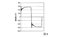
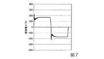
図4〜図7は、表1中に示す上記放電ランプ10の駆動電力毎の上記放電ランプ10に供給される駆動電流の波形図を表したものである。なお、図4は、表1中に示す駆動電力が280W(定格電力比100%)のときオーバーシュート率を10%に設定した場合の駆動電流の波形図である。図5は、表1中に示す駆動電力が250W(定格電力比90%)のときオーバーシュート率を15%に設定した場合の駆動電流の波形図である。図6は、表1中に示す駆動電力が200W(定格電力比70%)のときオーバーシュート率を20%に設定した場合の駆動電流の波形図である。図7は、表1中に示す駆動電力が170W(定格電力比60%)のときオーバーシュート率を30%に設定した場合の駆動電流の波形図である。
4 to 7 show waveform diagrams of the drive current supplied to the
上記式(1)から、オーバーシュート率Zの上限については、この「−0.45W+60」の値を超えないように設定を行うことが好ましい。一方、オーバーシュート率Zの下限については、駆動電流の波形や駆動電力等を正確に制御でき、なお且つ、上記放電ランプ10の照度変化によりプロジェクター1の投影画像にちらつきが発生しない範囲で設定を行うことが好ましい。
From the above formula (1), the upper limit of the overshoot rate Z is preferably set so as not to exceed the value of “−0.45 W + 60”. On the other hand, the lower limit of the overshoot rate Z is set within a range in which the waveform of the drive current, the drive power, etc. can be accurately controlled, and the flickering does not occur in the projected image of the
上記ランプ点灯装置70では、図4〜図7に示すように、上記放電ランプ10の駆動電力が大きいときほど、オーバーシュートOS及びアンダーシュードUSの電流値を下げる制御が行われる。逆に、上記ランプ点灯装置70では、上記放電ランプ10の駆動電力が小さいときほど、オーバーシュートOS及びアンダーシュードUSの電流値を上げる制御が行われる。
In the
上記放電ランプ10の駆動電力が高い場合には、上記放電ランプ10の電極は高温による突起溶融のため放電が安定し、ちらつきが発生しにくい。このため、上記制御部76の応答速度の低下をある程度許容しつつ、上記放電ランプ10へのダメージのリスクを抑えるため、オーバーシュートOS及びアンダーシュードUSの電流値を下げる制御を行う。これにより、オーバーシュートOS及びアンダーシュードUSの電流値を相対的に小さくして、オーバーシュートOS及びアンダーシュートUSの発生による影響を低く抑えることができる。
When the driving power of the
これに対して、上記放電ランプ10の駆動電力が低い場合には、上記放電ランプ10の電極は溶融しづらくなり、ちらつきのリスクが高まる。一方、上記放電ランプ10の駆動電力は低いため、上記放電ランプ10へのダメージのリスクは高電力駆動時よりも低い。そこで、オーバーシュートOS及びアンダーシュートUSの電流値を過多に抑制せず、上記制御部76の応答速度を上げながら駆動電流の波形を正確に制御できるように、オーバーシュートOS及びアンダーシュードUSの電流値を上げる制御を行う。これにより、オーバーシュートOS及びアンダーシュードUSの電流値を相対的に大きくして、上記放電ランプ10の点灯制御を適切に行うことができる。
On the other hand, when the driving power of the
また、本発明による点灯制御では、上記放電ランプ10の駆動モードに応じて、その駆動電流の波形に発生するオーバーシュートOS及びアンダーシュートUSの電流値を異ならせることを特徴とする。
The lighting control according to the present invention is characterized in that the current values of the overshoot OS and the undershoot US generated in the waveform of the drive current are made different according to the drive mode of the
具体的に、本発明による点灯制御では、上記放電ランプ10の駆動モードに応じて、上記放電ランプ10の平均駆動周波数が高いときに、オーバーシュートOS及びアンダーシュートUSの電流値を相対的に小さくする方向に調整を行い、上記放電ランプ10の平均駆動周波数が低いときに、オーバーシュートOS及びアンダーシュートUSの電流値を相対的に大きくする方向に調整を行う。
Specifically, in the lighting control according to the present invention, when the average driving frequency of the
上記放電ランプ10の駆動電力が同じで上記放電ランプの駆動モードが異なる場合は、上記放電ランプの平均駆動周波数が高い駆動モードほど、オーバーシュートOS及びアンダーシュートUSの発生によるリスクが大きい。
When the drive power of the
そこで、上記放電ランプ10の駆動電力毎に設定されたオーバーシュートOS及びアンダーシュードUSの電流値に対して、平均駆動周波数の違いによって乗算される係数(以下、オーバーシュート係数という。)を決定する。
Therefore, a coefficient (hereinafter referred to as an overshoot coefficient) to be multiplied by the difference in the average drive frequency with respect to the current values of the overshoot OS and the undershoot US set for each drive power of the
例えば、表2は、上記放電ランプ10の駆動モードのうち、平均駆動周波数が高い場合(駆動モードA)と、平均駆動周波数が低い場合(駆動モードB)のオーバーシュート係数を例示したものである。
For example, Table 2 illustrates the overshoot coefficient when the average drive frequency is high (drive mode A) and when the average drive frequency is low (drive mode B) among the drive modes of the
上記ランプ点灯装置70では、上記放電ランプ10の平均駆動周波数が高いほど、オーバーシュートOS及びアンダーシュードUSの電流値を下げる制御が行われる。逆に、上記放電ランプ10の平均駆動周波数が低いほど、オーバーシュートOS及びアンダーシュードUSの電流値を上げる制御が行われる。
In the
このように、上記放電ランプ10の平均駆動周波数が高い駆動モードでは、上記制御部76に早い応答性が求められるが、オーバーシュートOS及びアンダーシュートUSによる上記放電ランプ10へのリスクとの兼ね合いを考え、オーバーシュートOS及びアンダーシュードUSの電流値を設定することが好ましい。
As described above, in the driving mode in which the average driving frequency of the
これにより、オーバーシュートOS及びアンダーシュートUSの発生による影響を低く抑えつつ、上記放電ランプ10の点灯制御を適切に行うことができる。
Thereby, the lighting control of the
また、本発明による点灯制御では、上記放電ランプ10の駆動モードに応じて、上記放電ランプ10の駆動周波数の変動幅が大きくなるときに、オーバーシュートOS及びアンダーシュートUSの電流値を相対的に大きくする方向に調整を行う。
Further, in the lighting control according to the present invention, when the fluctuation range of the driving frequency of the
具体的に、上記放電ランプ点灯装置70では、例えば図8に示すように、上記放電ランプ10を点灯させる際の駆動モードによって駆動周波数が急激に変化する場合がある。なお、図8は、駆動電流の波形図において、上記放電ランプ10の駆動周波数が変化する場合を例示したものである。
Specifically, in the discharge
図8中に示す駆動電流の波形図において、駆動周波数が500Hzから100Hzに切り替わる部分と、駆動周波数が100Hzから500Hzに切り替わる部分で、駆動周波数の変動幅が大きくなっている。そして、これらの部分において、オーバーシュートOS及びアンダーシュードUSの電流値を過多に抑制すると、上記制御部76の応答性が低下し、駆動電流の波形を正確に出力できなくなる。
In the waveform diagram of the drive current shown in FIG. 8, the fluctuation range of the drive frequency is large at the portion where the drive frequency is switched from 500 Hz to 100 Hz and at the portion where the drive frequency is switched from 100 Hz to 500 Hz. If the current values of the overshoot OS and the undershoot US are excessively suppressed in these portions, the responsiveness of the
そこで、上記放電ランプ10の駆動電力毎に設定されたオーバーシュートOS及びアンダーシュードUSの電流値に対して、駆動周波数の変動幅の違いによって乗算されるオーバーシュート係数を決定する。
Therefore, an overshoot coefficient is determined by multiplying the current values of the overshoot OS and the undershoot US set for each drive power of the
例えば、表3は、上記放電ランプ10の駆動モードのうち、駆動周波数の変動幅が大きい場合(駆動モードC)と、駆動周波数の変動幅が小さい場合(駆動モードD)のオーバーシュート係数を例示したものである。
For example, Table 3 exemplifies overshoot coefficients when the fluctuation range of the driving frequency is large (driving mode C) and the fluctuation range of the driving frequency is small (driving mode D) among the driving modes of the
上記ランプ点灯装置70では、上記放電ランプ10の駆動周波数の変動幅が大きいほど、オーバーシュートOS及びアンダーシュードUSの電流値を相対的に大きくする制御が行われる。これにより、駆動電流の波形や駆動電力等を正確に制御でき、なお且つ、上記放電ランプ10の照度変化によりプロジェクター1の投影画像にちらつきが発生しない範囲で設定を行うことができる。
In the
表4は、上記放電ランプ10に供給される駆動電力の大きさと、上記放電ランプ10の駆動モードに応じて設定されるオーバーシュート係数とから求まるオーバーシュート率Zをまとめたものである。
Table 4 summarizes the overshoot rate Z obtained from the magnitude of the drive power supplied to the
本発明による点灯制御では、上記放電ランプ10に供給される駆動電力の大きさに応じたオーバーシュートOS及びアンダーシュートUSの電流値に、上記放電ランプ10の駆動モードに応じたオーバーシュート係数を乗算した電流値とする制御を行う。
In the lighting control according to the present invention, the current values of the overshoot OS and the undershoot US corresponding to the magnitude of the drive power supplied to the
すなわち、本発明による点灯制御では、上記放電ランプ10の駆動電力毎に設定された電流値に、駆動モード毎に設定されたオーバーシュート係数を乗算することによって、上記放電ランプ10の駆動電力及び駆動モードに応じたオーバーシュートOS及びアンダーシュードUSの電流値の設定を行う。
That is, in the lighting control according to the present invention, the current value set for each driving power of the
これにより、上記放電ランプ10に供給される駆動電力の大きさに応じたオーバーシュートOS及びアンダーシュートUSの電流値の調整と、上記放電ランプ10の駆動モードに応じたオーバーシュートOS及びアンダーシュートUSの電流値の調整との両立を図りながら、上述したオーバーシュートOS及びアンダーシュートUSの発生による影響を抑えると共に、上記放電ランプ10の点灯制御を適切に行うことができる。
As a result, the current values of the overshoot OS and undershoot US corresponding to the magnitude of the driving power supplied to the
以上のように、本発明による上記放電ランプ10の点灯制御を行うことで、オーバーシュートOS及びアンダーシュートUSの発生によって上記放電ランプ10に黒化やコイル破壊等が発生するリスクと、上記放電ランプ10の照度変化によって投影画像にちらつきが発生するリスクとを回避することが可能である。
As described above, by performing the lighting control of the
したがって、上記プロジェクター1では、上述したオーバーシュートOS及びアンダーシュートUSの発生による影響を抑えつつ、上記放電ランプ10の点灯制御を適切に行うことができる放電ランプ点灯装置70を備えることで、更なる品質の向上を図ることが可能である。
Therefore, the
1…プロジェクター 10…放電ランプ(光源) 20…液晶パネル(光変調装置) 30…投射光学系 40…インターフェイス部 50…画像処理部 60…液晶パネル駆動部 70…放電ランプ点灯装置 71…ダウンチョッパー部 72…電力変換部 73…共振回路部 74…電圧検出部 75…点灯検出部 76…制御部 77…駆動部 80…CPU
DESCRIPTION OF
Claims (9)
前記放電ランプに駆動電流を供給する駆動部と、
前記駆動部を制御する制御部と、を備え、
前記制御部は、前記駆動電流の駆動周波数に応じて、前記駆動電流におけるオーバーシュート及びアンダーシュートの電流値を変化させることを特徴とする放電ランプ点灯装置。 A discharge lamp lighting device for controlling lighting of a discharge lamp,
A driving unit for supplying a driving current to the discharge lamp;
A control unit for controlling the drive unit,
The control unit changes a current value of overshoot and undershoot in the drive current in accordance with a drive frequency of the drive current.
前記制御部は、前記駆動電流の平均駆動周波数が第1駆動周波数である場合の前記オーバーシュート及び前記アンダーシュートの電流値を、前記平均駆動周波数が前記第1駆動周波数よりも低い第2駆動周波数である場合の前記オーバーシュート及び前記アンダーシュートの電流値よりも小さくすることを特徴とする放電ランプ点灯装置。 The discharge lamp lighting device according to claim 1 ,
The control unit determines the current values of the overshoot and the undershoot when the average drive frequency of the drive current is the first drive frequency, and the second drive frequency where the average drive frequency is lower than the first drive frequency. The discharge lamp lighting device is made smaller than the current values of the overshoot and the undershoot in the case of.
前記制御部は、前記駆動電流の前記駆動周波数の変動幅が第1の値である場合の前記オーバーシュート及び前記アンダーシュートの電流値を、前記変動幅が前記第1の値よりも小さい第2の値である場合の前記オーバーシュート及び前記アンダーシュートの電流値よりも大きくすることを特徴とする放電ランプ点灯装置。 The discharge lamp lighting device according to claim 1 or 2 ,
The control unit determines a current value of the overshoot and the undershoot when the fluctuation range of the driving frequency of the driving current is a first value, and a second value in which the fluctuation range is smaller than the first value. The discharge lamp lighting device is configured to be larger than the current values of the overshoot and the undershoot in the case of the above value.
前記制御部は、前記放電ランプに供給される駆動電力の大きさに応じて、前記駆動電流における前記オーバーシュート及び前記アンダーシュートの電流値を変化させることを特徴とする放電ランプ点灯装置。The control unit changes the current values of the overshoot and the undershoot in the drive current according to the magnitude of the drive power supplied to the discharge lamp.
前記制御部は、前記駆動電力が第1駆動電力である場合の前記オーバーシュート及び前記アンダーシュートの電流値を、前記駆動電力が前記第1駆動電力よりも小さい第2駆動電力である場合の前記オーバーシュート及び前記アンダーシュートの電流値よりも小さくすることを特徴とする放電ランプ点灯装置。 The discharge lamp lighting device according to claim 4 ,
The control unit determines the current values of the overshoot and the undershoot when the drive power is the first drive power, and the current value when the drive power is the second drive power smaller than the first drive power. A discharge lamp lighting device characterized in that the current value of overshoot and undershoot is smaller.
前記制御部は、前記駆動電力の大きさに応じた前記オーバーシュート及び前記アンダーシュートの電流値に、前記駆動電流の前記駆動周波数に応じた係数を乗算した電流値とすることを特徴とする放電ランプ点灯装置。 The discharge lamp lighting device according to claim 4 or 5 ,
The control unit has a current value obtained by multiplying a current value of the overshoot and the undershoot according to the magnitude of the drive power by a coefficient according to the drive frequency of the drive current. Lamp lighting device.
前記駆動部は、入力される直流電力を所定の出力電圧に降下して出力するダウンチョッパー部と、前記ダウンチョッパー部から供給される直流電力を交流電力に変換して出力する電力変換部と、を有し、
前記ダウンチョッパー部は、前記ダウンチョッパー部に電力を供給する電源と前記電力変換部との間に接続されたスイッチング素子を有し、
前記ダウンチョッパー部は、前記制御部からの制御信号に基づいて前記スイッチング素子のオン/オフを切り替えることにより、前記スイッチング素子のデューティー比に応じた出力電圧に変換された直流電力を出力し、
前記制御部は、前記デューティー比を調整することによって、前記オーバーシュート及び前記アンダーシュートの電流値を変化させることを特徴とする放電ランプ点灯装置。 The discharge lamp lighting device according to any one of claims 1 to 6,
The drive unit includes a down chopper unit that outputs and outputs input DC power to a predetermined output voltage, a power conversion unit that converts DC power supplied from the down chopper unit into AC power, and outputs the AC power, Have
The down chopper unit has a switching element connected between a power source that supplies power to the down chopper unit and the power conversion unit,
The down chopper unit outputs DC power converted into an output voltage corresponding to a duty ratio of the switching element by switching on / off the switching element based on a control signal from the control unit,
The discharge lamp lighting device, wherein the control unit changes the current values of the overshoot and the undershoot by adjusting the duty ratio.
前記放電ランプに駆動電流を供給するステップと、
前記駆動電流の駆動周波数に応じて、前記駆動電流におけるオーバーシュート及びアンダーシュートの電流値を変化させるステップと、
を備えることを特徴とする放電ランプ点灯方法。 A discharge lamp lighting method for controlling lighting of a discharge lamp,
Supplying a driving current to the discharge lamp;
Changing a current value of overshoot and undershoot in the drive current according to a drive frequency of the drive current;
A discharge lamp lighting method comprising:
請求項1から7の何れか一項に記載の放電ランプ点灯装置と、
前記放電ランプからの光を画像データに応じて変調する光変調装置と、
前記光変調装置により変調された光を投射する投射光学系と、を備えたプロジェクター。 A discharge lamp that emits light;
A discharge lamp lighting device according to any one of claims 1 to 7,
A light modulation device that modulates light from the discharge lamp according to image data;
A projection optical system that projects light modulated by the light modulation device.
Priority Applications (2)
| Application Number | Priority Date | Filing Date | Title |
|---|---|---|---|
| JP2013234709A JP6252121B2 (en) | 2013-01-07 | 2013-11-13 | Discharge lamp lighting device, discharge lamp lighting method, and projector |
| US14/134,269 US9288884B2 (en) | 2013-01-07 | 2013-12-19 | Discharge lamp lighting device, discharge lamp lighting method, and projector |
Applications Claiming Priority (3)
| Application Number | Priority Date | Filing Date | Title |
|---|---|---|---|
| JP2013000368 | 2013-01-07 | ||
| JP2013000368 | 2013-01-07 | ||
| JP2013234709A JP6252121B2 (en) | 2013-01-07 | 2013-11-13 | Discharge lamp lighting device, discharge lamp lighting method, and projector |
Publications (3)
| Publication Number | Publication Date |
|---|---|
| JP2014146591A JP2014146591A (en) | 2014-08-14 |
| JP2014146591A5 JP2014146591A5 (en) | 2016-10-27 |
| JP6252121B2 true JP6252121B2 (en) | 2017-12-27 |
Family
ID=51060481
Family Applications (1)
| Application Number | Title | Priority Date | Filing Date |
|---|---|---|---|
| JP2013234709A Active JP6252121B2 (en) | 2013-01-07 | 2013-11-13 | Discharge lamp lighting device, discharge lamp lighting method, and projector |
Country Status (2)
| Country | Link |
|---|---|
| US (1) | US9288884B2 (en) |
| JP (1) | JP6252121B2 (en) |
Families Citing this family (1)
| Publication number | Priority date | Publication date | Assignee | Title |
|---|---|---|---|---|
| JP2017054777A (en) * | 2015-09-11 | 2017-03-16 | セイコーエプソン株式会社 | Discharge lamp drive device, light source device, projector and discharge lamp drive method |
Family Cites Families (18)
| Publication number | Priority date | Publication date | Assignee | Title |
|---|---|---|---|---|
| JP3259163B2 (en) | 1996-02-22 | 2002-02-25 | スタンレー電気株式会社 | Discharge lamp lighting device |
| JP4134611B2 (en) | 2002-07-02 | 2008-08-20 | ウシオ電機株式会社 | High pressure discharge lamp lighting device |
| JP2004296119A (en) * | 2003-03-25 | 2004-10-21 | Tdk Corp | Device for lighting discharge lamp |
| EP1624732A4 (en) * | 2003-05-14 | 2009-01-21 | Panasonic Corp | Device and method for lighting high-voltage discharge lamp |
| JP4017647B2 (en) | 2006-01-19 | 2007-12-05 | Tdk株式会社 | Discharge lamp lighting device |
| US20110025233A1 (en) * | 2008-04-14 | 2011-02-03 | Morales Louis J | Method and Apparatus For Reduction of Excess Current During Initial Firing of Arc Lamp Circuits |
| JP2010129612A (en) * | 2008-11-25 | 2010-06-10 | Panasonic Electric Works Co Ltd | Lighting device |
| TWI388115B (en) * | 2009-08-13 | 2013-03-01 | Green Solution Tech Co Ltd | Power conversion drive circuit and lamp drive circuit |
| JP5153003B2 (en) * | 2009-08-19 | 2013-02-27 | ウシオ電機株式会社 | High pressure discharge lamp lighting device and projector |
| KR20120091307A (en) * | 2009-11-06 | 2012-08-17 | 코닌클리즈케 필립스 일렉트로닉스 엔.브이. | Lighting device |
| US8531131B2 (en) * | 2010-09-22 | 2013-09-10 | Osram Sylvania Inc. | Auto-sensing switching regulator to drive a light source through a current regulator |
| US9198256B2 (en) * | 2010-12-21 | 2015-11-24 | Koninklijke Philips N.V. | Method and apparatus to limit current overshoot and undershoot in light driver |
| US8405316B2 (en) * | 2010-12-29 | 2013-03-26 | Stmicroelectronics S.R.L. | Control device for a discharge lamp |
| US9137872B2 (en) * | 2011-01-11 | 2015-09-15 | Mitsubishi Electric Corporation | LED lighting device |
| JP5531316B2 (en) * | 2012-11-16 | 2014-06-25 | ポルティオアレンディ | Cross-flow power booster and AC / DC lighting power supply controller |
| US8957934B2 (en) * | 2012-11-21 | 2015-02-17 | Ricoh Company, Ltd. | Light source drive circuit, optical scanning apparatus, semiconductor drive circuit, and image forming apparatus |
| US9661697B2 (en) * | 2013-03-14 | 2017-05-23 | Laurence P. Sadwick | Digital dimmable driver |
| TW201505310A (en) * | 2013-07-16 | 2015-02-01 | Energy Pro Technology Co Ltd | Light emitting diode apparatus with over current protection function and system for the same |
-
2013
- 2013-11-13 JP JP2013234709A patent/JP6252121B2/en active Active
- 2013-12-19 US US14/134,269 patent/US9288884B2/en not_active Expired - Fee Related
Also Published As
| Publication number | Publication date |
|---|---|
| US9288884B2 (en) | 2016-03-15 |
| US20140191685A1 (en) | 2014-07-10 |
| JP2014146591A (en) | 2014-08-14 |
Similar Documents
| Publication | Publication Date | Title |
|---|---|---|
| JP4321136B2 (en) | Discharge lamp lighting device | |
| JP4853638B2 (en) | High pressure discharge lamp lighting device | |
| JP2006049028A (en) | Discharge lamp lighting device | |
| JP2006277983A (en) | Discharge lamp driving device | |
| JP5239729B2 (en) | High pressure discharge lamp lighting device, light source device, and high pressure discharge lamp lighting method | |
| JP4182081B2 (en) | Discharge lamp driving device | |
| US9363875B2 (en) | Discharge lamp lighting device, discharge lamp lighting method, and projector device | |
| JP6252121B2 (en) | Discharge lamp lighting device, discharge lamp lighting method, and projector | |
| JP2006202775A (en) | Lighting device for high-pressure discharge lamp | |
| JP4193798B2 (en) | Discharge tube lighting device | |
| JP2003264094A (en) | Lighting control circuit for discharge lamp and method for adjusting discharge gap | |
| JP2014191261A (en) | Projector and drive control method | |
| JP2011090938A (en) | High pressure discharge lamp lighting device, projector, and lighting method of high pressure discharge lamp | |
| US9709881B2 (en) | Discharge lamp lighting device, discharge lamp lighting method, and projector | |
| JP4265732B2 (en) | Lamp lighting device and projector using the same | |
| US20090278468A1 (en) | Device and Method for Operating a High-Pressure Discharge Lamp | |
| JP6558018B2 (en) | Discharge lamp driving device, light source device, projector, and discharge lamp driving method | |
| JP6182863B2 (en) | Discharge lamp lighting device, discharge lamp lighting method, and projector | |
| JP4059053B2 (en) | Lighting method of high pressure discharge lamp | |
| JP4650623B2 (en) | Discharge lamp lighting device | |
| JP5170596B2 (en) | High pressure discharge lamp lighting device and light source device | |
| JP2005327661A (en) | Lighting device of high-pressure discharge lamp, and electronic apparatus using it | |
| JP6127567B2 (en) | Discharge lamp driving device, projector, and discharge lamp driving method | |
| JP5853222B2 (en) | Discharge lamp lighting device | |
| JP2016162581A (en) | Discharge lamp driving device, light source device and projector |
Legal Events
| Date | Code | Title | Description |
|---|---|---|---|
| RD04 | Notification of resignation of power of attorney |
Free format text: JAPANESE INTERMEDIATE CODE: A7424 Effective date: 20150109 |
|
| RD04 | Notification of resignation of power of attorney |
Free format text: JAPANESE INTERMEDIATE CODE: A7424 Effective date: 20160610 |
|
| RD03 | Notification of appointment of power of attorney |
Free format text: JAPANESE INTERMEDIATE CODE: A7423 Effective date: 20160624 |
|
| A521 | Written amendment |
Free format text: JAPANESE INTERMEDIATE CODE: A523 Effective date: 20160908 |
|
| A621 | Written request for application examination |
Free format text: JAPANESE INTERMEDIATE CODE: A621 Effective date: 20160908 |
|
| A977 | Report on retrieval |
Free format text: JAPANESE INTERMEDIATE CODE: A971007 Effective date: 20170615 |
|
| A131 | Notification of reasons for refusal |
Free format text: JAPANESE INTERMEDIATE CODE: A131 Effective date: 20170620 |
|
| A521 | Written amendment |
Free format text: JAPANESE INTERMEDIATE CODE: A523 Effective date: 20170808 |
|
| TRDD | Decision of grant or rejection written | ||
| A01 | Written decision to grant a patent or to grant a registration (utility model) |
Free format text: JAPANESE INTERMEDIATE CODE: A01 Effective date: 20171031 |
|
| A61 | First payment of annual fees (during grant procedure) |
Free format text: JAPANESE INTERMEDIATE CODE: A61 Effective date: 20171113 |
|
| R150 | Certificate of patent or registration of utility model |
Ref document number: 6252121 Country of ref document: JP Free format text: JAPANESE INTERMEDIATE CODE: R150 |