JP6250736B2 - A supported self-optimizing wireless network that is optimized for energy, mobility and capacity - Google Patents
A supported self-optimizing wireless network that is optimized for energy, mobility and capacity Download PDFInfo
- Publication number
- JP6250736B2 JP6250736B2 JP2016111294A JP2016111294A JP6250736B2 JP 6250736 B2 JP6250736 B2 JP 6250736B2 JP 2016111294 A JP2016111294 A JP 2016111294A JP 2016111294 A JP2016111294 A JP 2016111294A JP 6250736 B2 JP6250736 B2 JP 6250736B2
- Authority
- JP
- Japan
- Prior art keywords
- cell
- transmission
- cells
- series
- coverage area
- Prior art date
- Legal status (The legal status is an assumption and is not a legal conclusion. Google has not performed a legal analysis and makes no representation as to the accuracy of the status listed.)
- Active
Links
- 230000005540 biological transmission Effects 0.000 claims description 303
- 238000005259 measurement Methods 0.000 claims description 144
- 230000001965 increasing effect Effects 0.000 claims description 29
- 230000003595 spectral effect Effects 0.000 claims description 15
- 230000000694 effects Effects 0.000 claims description 12
- 238000012545 processing Methods 0.000 claims description 10
- 230000002596 correlated effect Effects 0.000 claims description 4
- 108091028733 RNTP Proteins 0.000 claims 2
- 238000000034 method Methods 0.000 description 93
- 238000004891 communication Methods 0.000 description 63
- 238000010586 diagram Methods 0.000 description 41
- 230000000875 corresponding effect Effects 0.000 description 39
- 238000005457 optimization Methods 0.000 description 30
- 230000011664 signaling Effects 0.000 description 19
- 230000008569 process Effects 0.000 description 17
- 230000008859 change Effects 0.000 description 16
- 230000006870 function Effects 0.000 description 9
- 238000005516 engineering process Methods 0.000 description 6
- 230000015572 biosynthetic process Effects 0.000 description 5
- 239000000463 material Substances 0.000 description 5
- 239000007787 solid Substances 0.000 description 4
- 230000006872 improvement Effects 0.000 description 3
- 238000001228 spectrum Methods 0.000 description 3
- 230000003044 adaptive effect Effects 0.000 description 2
- 230000008901 benefit Effects 0.000 description 2
- 239000000969 carrier Substances 0.000 description 2
- 230000003247 decreasing effect Effects 0.000 description 2
- 230000007774 longterm Effects 0.000 description 2
- 238000010295 mobile communication Methods 0.000 description 2
- 238000013146 percutaneous coronary intervention Methods 0.000 description 2
- 230000009471 action Effects 0.000 description 1
- 238000013459 approach Methods 0.000 description 1
- 238000003491 array Methods 0.000 description 1
- 230000009286 beneficial effect Effects 0.000 description 1
- 230000020411 cell activation Effects 0.000 description 1
- 239000003795 chemical substances by application Substances 0.000 description 1
- 239000012141 concentrate Substances 0.000 description 1
- 230000001276 controlling effect Effects 0.000 description 1
- 238000007796 conventional method Methods 0.000 description 1
- 125000004122 cyclic group Chemical group 0.000 description 1
- 238000013461 design Methods 0.000 description 1
- 230000002708 enhancing effect Effects 0.000 description 1
- 230000007613 environmental effect Effects 0.000 description 1
- 230000014509 gene expression Effects 0.000 description 1
- 230000012447 hatching Effects 0.000 description 1
- 239000004973 liquid crystal related substance Substances 0.000 description 1
- 230000003287 optical effect Effects 0.000 description 1
- 238000005192 partition Methods 0.000 description 1
- 230000004044 response Effects 0.000 description 1
- 239000004065 semiconductor Substances 0.000 description 1
- 230000007704 transition Effects 0.000 description 1
Images


Classifications
-
- H—ELECTRICITY
- H04—ELECTRIC COMMUNICATION TECHNIQUE
- H04W—WIRELESS COMMUNICATION NETWORKS
- H04W74/00—Wireless channel access, e.g. scheduled or random access
- H04W74/08—Non-scheduled or contention based access, e.g. random access, ALOHA, CSMA [Carrier Sense Multiple Access]
- H04W74/0808—Non-scheduled or contention based access, e.g. random access, ALOHA, CSMA [Carrier Sense Multiple Access] using carrier sensing, e.g. as in CSMA
-
- H—ELECTRICITY
- H04—ELECTRIC COMMUNICATION TECHNIQUE
- H04B—TRANSMISSION
- H04B7/00—Radio transmission systems, i.e. using radiation field
- H04B7/24—Radio transmission systems, i.e. using radiation field for communication between two or more posts
- H04B7/26—Radio transmission systems, i.e. using radiation field for communication between two or more posts at least one of which is mobile
- H04B7/2621—Radio transmission systems, i.e. using radiation field for communication between two or more posts at least one of which is mobile using frequency division multiple access [FDMA]
-
- H—ELECTRICITY
- H04—ELECTRIC COMMUNICATION TECHNIQUE
- H04W—WIRELESS COMMUNICATION NETWORKS
- H04W24/00—Supervisory, monitoring or testing arrangements
- H04W24/02—Arrangements for optimising operational condition
-
- H—ELECTRICITY
- H04—ELECTRIC COMMUNICATION TECHNIQUE
- H04J—MULTIPLEX COMMUNICATION
- H04J11/00—Orthogonal multiplex systems, e.g. using WALSH codes
- H04J11/0023—Interference mitigation or co-ordination
-
- H—ELECTRICITY
- H04—ELECTRIC COMMUNICATION TECHNIQUE
- H04L—TRANSMISSION OF DIGITAL INFORMATION, e.g. TELEGRAPHIC COMMUNICATION
- H04L5/00—Arrangements affording multiple use of the transmission path
- H04L5/0001—Arrangements for dividing the transmission path
- H04L5/0014—Three-dimensional division
- H04L5/0023—Time-frequency-space
-
- H—ELECTRICITY
- H04—ELECTRIC COMMUNICATION TECHNIQUE
- H04L—TRANSMISSION OF DIGITAL INFORMATION, e.g. TELEGRAPHIC COMMUNICATION
- H04L5/00—Arrangements affording multiple use of the transmission path
- H04L5/003—Arrangements for allocating sub-channels of the transmission path
- H04L5/0037—Inter-user or inter-terminal allocation
-
- H—ELECTRICITY
- H04—ELECTRIC COMMUNICATION TECHNIQUE
- H04L—TRANSMISSION OF DIGITAL INFORMATION, e.g. TELEGRAPHIC COMMUNICATION
- H04L5/00—Arrangements affording multiple use of the transmission path
- H04L5/003—Arrangements for allocating sub-channels of the transmission path
- H04L5/0044—Arrangements for allocating sub-channels of the transmission path allocation of payload
-
- H—ELECTRICITY
- H04—ELECTRIC COMMUNICATION TECHNIQUE
- H04L—TRANSMISSION OF DIGITAL INFORMATION, e.g. TELEGRAPHIC COMMUNICATION
- H04L5/00—Arrangements affording multiple use of the transmission path
- H04L5/003—Arrangements for allocating sub-channels of the transmission path
- H04L5/0048—Allocation of pilot signals, i.e. of signals known to the receiver
-
- H—ELECTRICITY
- H04—ELECTRIC COMMUNICATION TECHNIQUE
- H04L—TRANSMISSION OF DIGITAL INFORMATION, e.g. TELEGRAPHIC COMMUNICATION
- H04L5/00—Arrangements affording multiple use of the transmission path
- H04L5/003—Arrangements for allocating sub-channels of the transmission path
- H04L5/0053—Allocation of signaling, i.e. of overhead other than pilot signals
-
- H—ELECTRICITY
- H04—ELECTRIC COMMUNICATION TECHNIQUE
- H04L—TRANSMISSION OF DIGITAL INFORMATION, e.g. TELEGRAPHIC COMMUNICATION
- H04L5/00—Arrangements affording multiple use of the transmission path
- H04L5/003—Arrangements for allocating sub-channels of the transmission path
- H04L5/0058—Allocation criteria
- H04L5/0064—Rate requirement of the data, e.g. scalable bandwidth, data priority
-
- H—ELECTRICITY
- H04—ELECTRIC COMMUNICATION TECHNIQUE
- H04L—TRANSMISSION OF DIGITAL INFORMATION, e.g. TELEGRAPHIC COMMUNICATION
- H04L5/00—Arrangements affording multiple use of the transmission path
- H04L5/0091—Signaling for the administration of the divided path
- H04L5/0094—Indication of how sub-channels of the path are allocated
-
- H—ELECTRICITY
- H04—ELECTRIC COMMUNICATION TECHNIQUE
- H04L—TRANSMISSION OF DIGITAL INFORMATION, e.g. TELEGRAPHIC COMMUNICATION
- H04L5/00—Arrangements affording multiple use of the transmission path
- H04L5/14—Two-way operation using the same type of signal, i.e. duplex
-
- H—ELECTRICITY
- H04—ELECTRIC COMMUNICATION TECHNIQUE
- H04W—WIRELESS COMMUNICATION NETWORKS
- H04W28/00—Network traffic management; Network resource management
- H04W28/02—Traffic management, e.g. flow control or congestion control
-
- H—ELECTRICITY
- H04—ELECTRIC COMMUNICATION TECHNIQUE
- H04W—WIRELESS COMMUNICATION NETWORKS
- H04W28/00—Network traffic management; Network resource management
- H04W28/02—Traffic management, e.g. flow control or congestion control
- H04W28/0226—Traffic management, e.g. flow control or congestion control based on location or mobility
-
- H—ELECTRICITY
- H04—ELECTRIC COMMUNICATION TECHNIQUE
- H04W—WIRELESS COMMUNICATION NETWORKS
- H04W28/00—Network traffic management; Network resource management
- H04W28/02—Traffic management, e.g. flow control or congestion control
- H04W28/0268—Traffic management, e.g. flow control or congestion control using specific QoS parameters for wireless networks, e.g. QoS class identifier [QCI] or guaranteed bit rate [GBR]
-
- H—ELECTRICITY
- H04—ELECTRIC COMMUNICATION TECHNIQUE
- H04W—WIRELESS COMMUNICATION NETWORKS
- H04W36/00—Hand-off or reselection arrangements
- H04W36/08—Reselecting an access point
-
- H—ELECTRICITY
- H04—ELECTRIC COMMUNICATION TECHNIQUE
- H04W—WIRELESS COMMUNICATION NETWORKS
- H04W4/00—Services specially adapted for wireless communication networks; Facilities therefor
- H04W4/06—Selective distribution of broadcast services, e.g. multimedia broadcast multicast service [MBMS]; Services to user groups; One-way selective calling services
-
- H—ELECTRICITY
- H04—ELECTRIC COMMUNICATION TECHNIQUE
- H04W—WIRELESS COMMUNICATION NETWORKS
- H04W4/00—Services specially adapted for wireless communication networks; Facilities therefor
- H04W4/70—Services for machine-to-machine communication [M2M] or machine type communication [MTC]
-
- H—ELECTRICITY
- H04—ELECTRIC COMMUNICATION TECHNIQUE
- H04W—WIRELESS COMMUNICATION NETWORKS
- H04W72/00—Local resource management
- H04W72/04—Wireless resource allocation
-
- H—ELECTRICITY
- H04—ELECTRIC COMMUNICATION TECHNIQUE
- H04W—WIRELESS COMMUNICATION NETWORKS
- H04W72/00—Local resource management
- H04W72/04—Wireless resource allocation
- H04W72/044—Wireless resource allocation based on the type of the allocated resource
- H04W72/0446—Resources in time domain, e.g. slots or frames
-
- H—ELECTRICITY
- H04—ELECTRIC COMMUNICATION TECHNIQUE
- H04W—WIRELESS COMMUNICATION NETWORKS
- H04W72/00—Local resource management
- H04W72/20—Control channels or signalling for resource management
-
- H—ELECTRICITY
- H04—ELECTRIC COMMUNICATION TECHNIQUE
- H04W—WIRELESS COMMUNICATION NETWORKS
- H04W72/00—Local resource management
- H04W72/20—Control channels or signalling for resource management
- H04W72/23—Control channels or signalling for resource management in the downlink direction of a wireless link, i.e. towards a terminal
-
- H—ELECTRICITY
- H04—ELECTRIC COMMUNICATION TECHNIQUE
- H04W—WIRELESS COMMUNICATION NETWORKS
- H04W72/00—Local resource management
- H04W72/50—Allocation or scheduling criteria for wireless resources
- H04W72/54—Allocation or scheduling criteria for wireless resources based on quality criteria
- H04W72/542—Allocation or scheduling criteria for wireless resources based on quality criteria using measured or perceived quality
-
- H—ELECTRICITY
- H04—ELECTRIC COMMUNICATION TECHNIQUE
- H04W—WIRELESS COMMUNICATION NETWORKS
- H04W74/00—Wireless channel access, e.g. scheduled or random access
- H04W74/08—Non-scheduled or contention based access, e.g. random access, ALOHA, CSMA [Carrier Sense Multiple Access]
- H04W74/0833—Non-scheduled or contention based access, e.g. random access, ALOHA, CSMA [Carrier Sense Multiple Access] using a random access procedure
-
- H—ELECTRICITY
- H04—ELECTRIC COMMUNICATION TECHNIQUE
- H04W—WIRELESS COMMUNICATION NETWORKS
- H04W76/00—Connection management
- H04W76/10—Connection setup
-
- H—ELECTRICITY
- H04—ELECTRIC COMMUNICATION TECHNIQUE
- H04W—WIRELESS COMMUNICATION NETWORKS
- H04W76/00—Connection management
- H04W76/10—Connection setup
- H04W76/19—Connection re-establishment
-
- H—ELECTRICITY
- H04—ELECTRIC COMMUNICATION TECHNIQUE
- H04W—WIRELESS COMMUNICATION NETWORKS
- H04W92/00—Interfaces specially adapted for wireless communication networks
- H04W92/04—Interfaces between hierarchically different network devices
- H04W92/10—Interfaces between hierarchically different network devices between terminal device and access point, i.e. wireless air interface
-
- H—ELECTRICITY
- H04—ELECTRIC COMMUNICATION TECHNIQUE
- H04L—TRANSMISSION OF DIGITAL INFORMATION, e.g. TELEGRAPHIC COMMUNICATION
- H04L12/00—Data switching networks
- H04L12/02—Details
- H04L12/16—Arrangements for providing special services to substations
- H04L12/18—Arrangements for providing special services to substations for broadcast or conference, e.g. multicast
- H04L12/189—Arrangements for providing special services to substations for broadcast or conference, e.g. multicast in combination with wireless systems
-
- H—ELECTRICITY
- H04—ELECTRIC COMMUNICATION TECHNIQUE
- H04L—TRANSMISSION OF DIGITAL INFORMATION, e.g. TELEGRAPHIC COMMUNICATION
- H04L5/00—Arrangements affording multiple use of the transmission path
- H04L5/0001—Arrangements for dividing the transmission path
-
- H—ELECTRICITY
- H04—ELECTRIC COMMUNICATION TECHNIQUE
- H04W—WIRELESS COMMUNICATION NETWORKS
- H04W24/00—Supervisory, monitoring or testing arrangements
- H04W24/10—Scheduling measurement reports ; Arrangements for measurement reports
-
- H—ELECTRICITY
- H04—ELECTRIC COMMUNICATION TECHNIQUE
- H04W—WIRELESS COMMUNICATION NETWORKS
- H04W36/00—Hand-off or reselection arrangements
- H04W36/0005—Control or signalling for completing the hand-off
- H04W36/0011—Control or signalling for completing the hand-off for data sessions of end-to-end connection
- H04W36/0016—Hand-off preparation specially adapted for end-to-end data sessions
-
- Y—GENERAL TAGGING OF NEW TECHNOLOGICAL DEVELOPMENTS; GENERAL TAGGING OF CROSS-SECTIONAL TECHNOLOGIES SPANNING OVER SEVERAL SECTIONS OF THE IPC; TECHNICAL SUBJECTS COVERED BY FORMER USPC CROSS-REFERENCE ART COLLECTIONS [XRACs] AND DIGESTS
- Y02—TECHNOLOGIES OR APPLICATIONS FOR MITIGATION OR ADAPTATION AGAINST CLIMATE CHANGE
- Y02D—CLIMATE CHANGE MITIGATION TECHNOLOGIES IN INFORMATION AND COMMUNICATION TECHNOLOGIES [ICT], I.E. INFORMATION AND COMMUNICATION TECHNOLOGIES AIMING AT THE REDUCTION OF THEIR OWN ENERGY USE
- Y02D30/00—Reducing energy consumption in communication networks
- Y02D30/70—Reducing energy consumption in communication networks in wireless communication networks
Description
複数の異なるパラメータについて性能を改善するべく、無線ネットワークは自己最適化が可能である。無線ネットワークは、一の無線ネットワーク内の複数の送信セルにおいて変更を行うことによって、最適化することができる。自己最適化ネットワークにおいて、これらの変更は、当該ネットワーク自身によって決定され実施され得る。 The wireless network can be self-optimized to improve performance for multiple different parameters. A wireless network can be optimized by making changes in multiple transmission cells within one wireless network. In a self-optimizing network, these changes can be determined and implemented by the network itself.
自己最適化方法は現在、無線ネットワークにおいて適用されているが、適用対象のパラメータおよびその方法は限られている。自己最適化をネットワークに適用する方法が限られているので、自己最適化によってさまざまな方法で無線ネットワークが改善される可能性がある。このような改善を実現し得る方法はまだ発見に至っていない。しかし、適用方法が見つかったとしても、自己最適化方法を実現する場合にはいくつかの問題が生じ得る。 Self-optimizing methods are currently applied in wireless networks, but the parameters to be applied and their methods are limited. Since there are limited ways to apply self-optimization to the network, self-optimization can improve the wireless network in various ways. A method that can realize such an improvement has not yet been discovered. However, even if an application method is found, several problems can arise when implementing the self-optimization method.
無線ネットワークにおける自己最適化は、当該無線ネットワーク内での変更を含む。これらの変更を実施した後もネットワークが機能を実施し続けるか否かは、サポートインフラストラクチャ次第である。具体的には、無線ネットワークは依然として、当該ネットワークに含まれる送信セルで行われる変更に関わらず、当該ネットワーク内でモバイル通信デバイスにサービスを提供するためのインフラストラクチャが必要である。サポートインフラストラクチャの制限は、無線ネットワークの自己最適化の柔軟性を妨げる可能性がある。 Self-optimization in a wireless network includes changes within the wireless network. Whether or not the network continues to perform functions after making these changes depends on the support infrastructure. In particular, a wireless network still requires an infrastructure to provide services to mobile communication devices within the network, regardless of changes made in the transmission cells included in the network. Support infrastructure limitations may hamper the flexibility of wireless network self-optimization.
本発明の特徴および利点は、添付図面を参照しつつ以下に記載する詳細な説明から明らかになる。添付図面は、一例として、本発明の特徴を図示している。図面は以下の通りである。
本発明を開示および説明する前に、本発明は本明細書に開示した特定の構造、処理工程または材料に限定されるものではなく、当業者が認めるその均等物にまで拡張されることを理解されたい。また、本明細書で用いる用語は、具体例を説明することのみを目的として用いられ、限定を意図したものではないことも理解されたい。 Before disclosing and describing the present invention, it is understood that the present invention is not limited to the specific structures, processing steps or materials disclosed herein, but extends to equivalents recognized by those skilled in the art. I want to be. It is also to be understood that the terminology used herein is used for the purpose of describing specific examples only and is not intended to be limiting.
<定義>
本開示において記載する例が一般的であるという重要な意思表示として、第3世代パートナーシッププロジェクト(3GPP)ロングタームエボリューション(LTE)規格の用語を本明細書全体で多用するが、限定を意図したものではなく、この点をさらに伝えるべく本明細書の一部ではより一般的な用語を利用するという例外もある。
<Definition>
The third generation partnership project (3GPP) Long Term Evolution (LTE) standard terminology is used extensively throughout this specification as an important statement that the examples described in this disclosure are general, but are intended to be limiting Rather, there are exceptions where more general terminology is used in some of the specification to further convey this point.
無線モバイルデバイスの用語は、明細書毎に異なる用語が用いられる。本明細書で用いられる場合、無線モバイルデバイスは、他にもさまざまな呼称が考えられるが、ユーザイクイップメント(UE)または移動局(MS)である。本願において、無線モバイルデバイス、UEおよびMSという用語は、同義語として用いてよい。 The terminology for the wireless mobile device is different for each specification. As used herein, a wireless mobile device is a user equipment (UE) or a mobile station (MS), although various other names are possible. In this application, the terms wireless mobile device, UE and MS may be used as synonyms.
本明細書で用いる場合、「送信ノード」という用語は、セルと呼ばれる地理的領域に配置される複数の無線モバイルデバイスと通信するよう構成されているワイヤレスワイドエリアネットワーク(WWAN)内の無線通信デバイスと定義される。送信ノードの用語としては、明細書毎に異なる用語が用いられる。送信ノードのさまざまな変形例について用いられる用語は、これらに限定されないが、基地局(BS)、エボルブドNodeB(eNodeBまたはeNB)、WWAN送信ノード、送信ノード、無線送信ノードおよびWWANノードを含むとしてよい。これらの用語は、特に明記しない限り、同義語として用いられる。BSまたはeNodeBの実際の定義は、米国電気電子学会(IEEE)802.16および3GPPの仕様に定められている。 As used herein, the term “transmitting node” refers to a wireless communication device in a wireless wide area network (WWAN) that is configured to communicate with a plurality of wireless mobile devices located in a geographical area called a cell. Is defined. As the term of the transmission node, a different term is used for each specification. The terms used for the various variants of the transmitting node may include, but are not limited to, a base station (BS), an evolved NodeB (eNodeB or eNB), a WWAN transmitting node, a transmitting node, a wireless transmitting node and a WWAN node. . These terms are used synonymously unless otherwise specified. The actual definition of BS or eNodeB is defined in the Institute of Electrical and Electronics Engineers (IEEE) 802.16 and 3GPP specifications.
本明細書で用いる場合、「送信セル」という用語は、物理セル識別子(PCI)またはセル識別情報(Cell−ID)を割り当て可能なエンティティを意味する。本明細書において、Cell−IDおよびPCIという用語は、同義語として用いられ得る。例えば、送信セルは、一の送信ノードを意味するとしてよい。複数のPCI/Cell−IDを、周波数スペクトルのうち複数の異なる領域に対応する複数の異なるコンポーネントキャリア(CC)に割り当てることができるので、一の送信ノードは複数の送信セルを持つことができる。また、送信セルは、CCが複数の異なる送信ノードに関連する場合も、一の共通PCI/Cell−IDが割り当てられている複数の送信ノードおよび/またはCCを意味するとしてもよい。本願で用いる場合、「送信ノード/セル」は、送信ノード、送信セルまたはその両方を意味するとしてよい。 As used herein, the term “transmit cell” means an entity that can be assigned a physical cell identifier (PCI) or cell identification information (Cell-ID). In this specification, the terms Cell-ID and PCI may be used as synonyms. For example, a transmission cell may mean one transmission node. Since a plurality of PCI / Cell-IDs can be assigned to a plurality of different component carriers (CC) corresponding to a plurality of different regions in the frequency spectrum, one transmission node can have a plurality of transmission cells. Also, the transmission cell may mean a plurality of transmission nodes and / or CCs to which one common PCI / Cell-ID is assigned even when the CC is related to a plurality of different transmission nodes. As used herein, “transmission node / cell” may mean a transmission node, a transmission cell, or both.
本明細書で用いる場合、「実質的に」という用語は、動作、特徴、特性、状態、構造、事項または結果の程度または度合いが完全であるか、または、完全に近いことを意味する。例えば、「実質的に」包囲されている物体は、当該物体が完全に包囲されているか、または、略完全に包囲されていることを意味する。完全性からどの程度逸脱しているかについて正確に許容可能な程度は、場合によっては、具体的な文脈に応じて決まるとしてよい。しかし、一般的に言って、完全性が得られる場合と全体的に同じ結果が得られる程度に完全性に近いことと考えられる。「実質的に」という用語を用いることは、動作、特徴、特性、状態、構造、事項または結果が完全に、または、略完全に欠落していることを意味するべく否定的な意味で用いられる場合にも同様に利用され得る。 As used herein, the term “substantially” means that the degree or degree of operation, characteristic, property, state, structure, matter or result is complete or close to complete. For example, an object that is “substantially” enclosed means that the object is completely enclosed or substantially completely enclosed. The exact allowable degree of deviation from completeness may in some cases depend on the specific context. However, generally speaking, it is considered to be close to completeness to the extent that the same result is obtained as in the case where completeness is obtained. The use of the term “substantially” is used in a negative sense to mean that an action, feature, property, state, structure, matter or result is completely or nearly completely missing. The case can be used in the same way.
他の用語については、本明細書本文の別の箇所で定義するとしてよい。 Other terms may be defined elsewhere in the text of this specification.
<実施形態例>
最初に技術の例について概論を以下で述べた後、技術の具体的な例をさらに詳細に説明する。最初に記載する要約は、技術をより簡単に理解していただくためのものであるが、技術の重要な特徴または不可欠な特徴を特定することを意図したものではなく、請求対象の主題の範囲を限定することを意図したものでもない。
<Example Embodiment>
A general example of the technique is first described below, and then a specific example of the technique is described in more detail. The initial summary is intended to make the technology easier to understand, but is not intended to identify key or essential features of the technology, but rather covers the scope of the claimed subject matter. It is not intended to be limiting.
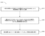
複数の実施形態例を、エボルブドパケットコア(EPC)等のコアネットワーク(CN)内に位置するエボルブドNodeB(eNodeB)および/またはオペレーションアンドメインテナンス(O&M)モジュールで実現することができる。エネルギー効率の最適化に関する特定の例では、選択されたカバレッジエリア内の一連の送信ノード/セルについて負荷情報を取得することができる。これらの送信ノード/セルのうち減数された一連の送信ノード/セルを、選択されたカバレッジエリアについてカバレッジとすることができるものとして選択することができる。減数された一連の送信ノード/セルは、選択されたカバレッジエリア内の複数のUEに送信された未設定の物理セル識別子(PCI)/セル識別情報(Cell−ID)に対応付けられるチャネル状態情報基準信号(CSI−RS)からの測定結果に基づいて選択され得る。 Several example embodiments may be implemented with an evolved NodeB (eNodeB) and / or an operation undomain tenancy (O & M) module located in a core network (CN) such as an evolved packet core (EPC). In a specific example for energy efficiency optimization, load information may be obtained for a set of transmitting nodes / cells within a selected coverage area. A reduced set of transmission nodes / cells of these transmission nodes / cells can be selected as being able to be covered for the selected coverage area. The decremented series of transmission nodes / cells is channel state information associated with unconfigured physical cell identifier (PCI) / cell identification information (Cell-ID) transmitted to a plurality of UEs in the selected coverage area. It can be selected based on the measurement result from the reference signal (CSI-RS).
未設定のPCI/Cell−IDに対応付けられるこれらのCSI−RSには、識別情報を埋め込むとしてよい。識別情報によって、CSI−RSのブロードキャスト先であるUEによって実施されるCSI−RSの測定が、未設定のPCI/Cell−IDに対応付けられることが可能になり、CSI−RSを送信する個別の送信ノード/セルで識別可能になる。この識別は、選択されたカバレッジエリアにおける複数の送信ノード/セルが一の共通セル識別情報(Cell−ID)を共有するにもかかわらず、可能である。このような測定は、比較的負荷が低い送信ノード/セルのカバレッジエリア内でUEとの間で十分な強度で送受信が可能な隣接する送信ノード/セルを指定することによって、減数された一連の送信ノード/セルを選択するために用いることができる。 Identification information may be embedded in these CSI-RSs associated with unset PCI / Cell-IDs. The identification information enables the CSI-RS measurement performed by the UE that is the broadcast destination of the CSI-RS to be associated with an unconfigured PCI / Cell-ID, and allows the individual CSI-RS to be transmitted. It becomes identifiable by the sending node / cell. This identification is possible even though multiple transmitting nodes / cells in the selected coverage area share one common cell identification information (Cell-ID). Such a measurement is reduced by specifying a neighboring transmitting node / cell that can transmit and receive with sufficient strength to and from the UE within the coverage area of the transmitting node / cell with relatively low load. Can be used to select a transmitting node / cell.
このような負荷の低い送信ノード/セルは、カバレッジエリアが隣接する送信ノード/セルによってカバーされており、選択されたカバレッジエリアを継続してカバーする減数された一連の送信ノード/セルから除外することが可能である。減数された一連の送信ノードに含まれる送信ノード/セルは、一の共通Cell−IDを持つ単一周波数ネットワーク(SFN)に再設定することができる。測定結果は未設定のPCI/Cell−IDに対応付けられ得るので、選択されたカバレッジエリアは、必ず、サービスを受信する送信ノード/セルが少なくなる。 Such lightly loaded transmission nodes / cells are excluded from the reduced series of transmission nodes / cells where the coverage area is covered by adjacent transmission nodes / cells and continues to cover the selected coverage area. It is possible. The transmission nodes / cells included in the reduced series of transmission nodes can be reconfigured to a single frequency network (SFN) with one common Cell-ID. Since the measurement result can be associated with an unconfigured PCI / Cell-ID, the selected coverage area always has fewer transmission nodes / cells that receive the service.
選択されたカバレッジエリアにおいて、UEをハンドオーバーする場合、および/または、UEを新しいPCI/Cell−IDで再設定する場合には、幾つかの方法を利用することができる。例えば、再設定メッセージを一連の送信ノード/セルに対応付けられている複数のUEに送信することができる。送信を停止させるための複数のUEに関する情報、新しいPCI/Cell−IDの値、および/または、新しいPCI/Cell−IDが動作可能となるタイミングを含む再設定メッセージは、一連の送信ノード/セルが新しいPCI/Cell−IDで再設定されると、UEを一連の送信ノード/セルに接続させるために送信することができる。再設定メッセージは、値タグおよび/またはページングメッセージに埋め込むことができる。別の例を挙げると、再設定メッセージは、マルチキャストシグナリングを利用して複数のUEに送信される共通ハンドオーバーコマンドメッセージを含むとしてよい。共通ハンドオーバーコマンドは、1または複数のセル無線ネットワーク一時的識別子(C−RNTI)、1または複数のターゲット送信ノード/セルセキュリティアルゴリズム識別子、専用ランダムアクセスチャネル(RACH)の情報、および/または、複数のUEについて新しいPCI/Cell−IDを持つ再設定された一連の送信ノード/セルへとハンドオーバーを実行するために用いられ得るターゲットeNodeBシステム情報等のパラメータを提供するとしてよい。 Several methods can be utilized when handing over a UE in a selected coverage area and / or reconfiguring the UE with a new PCI / Cell-ID. For example, the reconfiguration message can be transmitted to a plurality of UEs associated with a series of transmitting nodes / cells. A reconfiguration message including information on multiple UEs to stop transmission, a new PCI / Cell-ID value, and / or when a new PCI / Cell-ID becomes operational is a series of transmitting nodes / cells. Is reconfigured with a new PCI / Cell-ID, the UE can be sent to connect to a series of sending nodes / cells. The reset message can be embedded in the value tag and / or paging message. As another example, the reconfiguration message may include a common handover command message transmitted to multiple UEs using multicast signaling. The common handover command may include one or more cell radio network temporary identifiers (C-RNTI), one or more target transmission node / cell security algorithm identifiers, dedicated random access channel (RACH) information, and / or multiple May provide parameters such as target eNodeB system information that may be used to perform a handover to a reconfigured series of transmitting nodes / cells with a new PCI / Cell-ID for that UE.
幾つかの例を挙げると、共通Cell−IDを持つSFNを形成した後、1または複数の追加の送信ノード/セルが、選択されたカバレッジエリアにおいて、トラフィック負荷の増加に対する処理を改善し得ると決定するとしてよい。未設定のPCI/Cell−IDのための追加のCSI−RSを、上述したように、生成して送信するとしてよい。対応する測定結果を用いて、1または複数の追加の送信ノード/セルを1または複数の新しいPCI/Cell−IDで再設定するとしてよい。UEを1または複数の新しいPCI/Cell−IDを持つ送信ノード/セルへとハンドオーバーおよび/または再設定することはさらに、前述した例について説明した箇所に沿ったUE PCI/Cell−ID方法のハンドオーバーおよび/または再設定によって、容易になるとしてよい。 In some examples, after forming an SFN with a common Cell-ID, one or more additional transmitting nodes / cells may improve processing for increased traffic load in the selected coverage area. You may decide. An additional CSI-RS for an unconfigured PCI / Cell-ID may be generated and transmitted as described above. The corresponding measurement result may be used to reconfigure one or more additional transmitting nodes / cells with one or more new PCI / Cell-IDs. Handing over and / or reconfiguring the UE to a transmitting node / cell with one or more new PCI / Cell-IDs further includes the UE PCI / Cell-ID method according to the location described for the above example. It may be facilitated by handover and / or reconfiguration.
前述した未設定のPCI/Cell−IDおよびUEハンドオーバーおよびPCI/Cell−ID再設定についてCSI−RSを生成する例はさらに、高い移動度および負荷容量について変化する要求に適応するべく、ネットワークの自己最適化(SON)を容易にするとしてよい。例えば、負荷容量は、比較的低速度で移動する複数のユーザでトラフィックコンジェスチョンが深刻化し、その結果、データ量が多くなりセル間で発生するハンドオーバーが少ない期間の幹線道路において最も大きな懸念事項になり得る。しかし、トラフィックが少ない期間は、ユーザ数が大幅に少なくなり、ユーザは比較的高速度でエリアを移動する。トラフィックが少ない期間に移動速度が速くなると、トラフィックコンジェスチョンの例に比べると、各セルにおいてデータ量がかなり少なくなるが、ハンドオーバーの数がはるかに多くなる。このようなエリアのトラフィック負荷の量および/またはその内部に含まれるUEの速度に応じて、高移動度Cell−ID設定および高負荷容量Cell−ID設定のいずれかが選択され得る。 The example of generating a CSI-RS for unconfigured PCI / Cell-ID and UE handover and PCI / Cell-ID reconfiguration as described above is further adapted to meet changing requirements for high mobility and load capacity. Self-optimization (SON) may be facilitated. For example, load capacity is the biggest concern on highways during periods when traffic congestion is severe among multiple users moving at relatively low speeds, resulting in high data volume and low handovers between cells Can be. However, during periods of low traffic, the number of users is greatly reduced and users move in areas at relatively high speeds. If the movement speed increases during periods of low traffic, the amount of data in each cell is considerably less than in the traffic convergence example, but the number of handovers is much higher. Either the high mobility Cell-ID setting or the high load capacity Cell-ID setting may be selected according to the amount of traffic load in such an area and / or the speed of the UE included therein.
高移動度が優先事項の場合、エリア内の一連の送信ノード/セルは、上述した新しいハンドオーバー手順を用いて、SFNおよび共通PCI/Cell−IDにおいて設定され得る。共通PCI/Cell−IDを持つSFNは、高速度で移動するユーザについて、ハンドオーバーの発生回数を大幅に減らし得る。SFNおよび共通PCI/Cell−IDの場合、移動度オーバーヘッドは大幅に低減され高移動度が実現される。高容量が求められている場合、さまざまなPCI/Cell−IDを持つ複数の送信ノード/セルを実現することができる。異なるPCI/Cell−IDを持つこれらの複数の送信ノード/セルは、より高いスペクトル効率で増加した負荷に適応することができる。より少ないPCI/Cell−IDからより多いPCI/Cell−IDへの送信は、未設定のPCI/Cell−IDのためのCSI−RSおよび上述したハンドオーバー方式によって、容易になり得る。幾つかの実施形態例についての更なる詳細は、以下の図面を参照しつつ以下で説明する。 If high mobility is a priority, a series of transmitting nodes / cells in the area can be configured in SFN and common PCI / Cell-ID using the new handover procedure described above. An SFN having a common PCI / Cell-ID can significantly reduce the number of handover occurrences for users moving at high speed. In the case of SFN and common PCI / Cell-ID, mobility overhead is greatly reduced and high mobility is realized. When high capacity is required, a plurality of transmission nodes / cells having various PCI / Cell-IDs can be realized. These multiple transmitting nodes / cells with different PCI / Cell-IDs can accommodate increased loads with higher spectral efficiency. Transmission from fewer PCI / Cell-IDs to more PCI / Cell-IDs can be facilitated by the CSI-RS for unconfigured PCI / Cell-ID and the handover scheme described above. Further details about some example embodiments are described below with reference to the following drawings.
図1Aは、複数のUEを示す図である。そのうち、UE101a、101bは、基本カバレッジのeNodeB104aによってカバーされているSONの一部分102aにおけるさまざまな種類のUEの例である。特定の例によると、基本カバレッジのeNodeBは、マクロノード(MCN)eNodeBであってよい。一部分102a内にはさらに、ブースターカバレッジエリア108aを持つ容量ブースター106aが配置されている。図示しているように、ブースターカバレッジエリア108aは、基本カバレッジのeNodeB104aがカバーしている一部分102aの外側まで拡張し、自己最適化ネットワーク内の他の送信ノード/セルがカバーしているエリアまで拡張しているとしてよい。一実施形態によると、容量ブースターは、セルトラフィックのレベルがMCNのみで提供し得るレベルまで低減した場合に基本カバレッジについて必要になることなく、カバレッジのみを改善するか、または、容量を大きくすることができるので、基本カバレッジのeNodeBとは区別され得る。
FIG. 1A is a diagram illustrating a plurality of UEs. Of these, the
容量ブースター106aは、低電力ノード(LPN)であってよい。LPNは、マイクロセル、ピコセル、フェムトセル、ホームeNodeBセル(HeNB)、リモート無線ヘッド(RRH)、リモート無線イクイップメント(RRE)、リピータ、または、MCN eNodeBで通常用いられている電力より低い電力を持つその他の種類の送信ノードのうち1つを含むとしてよい。基本カバレッジのeNodeB104aおよび容量ブースター106aは、バックホールリンク110aを介して通信可能に結合されているとしてよい。バックホールリンクは通常、有線接続または光接続を用いて形成されている。バックホールリンクを介した通信は、一例でありこれに限定されないが、X2インターフェース等のインターフェースを用いて実現され得る。
The
図1Aに図示しているように、幾つかのUEがブースターカバレッジエリア108a内に存在する。基本カバレッジのeNodeB104aはこのため、図1Aに示すように、ブースターカバレッジエリアにおいて、容量を大きくし、UEのためのサービス品質を維持/改善するべく、容量ブースター106aをオンに制御することができる。しかし、容量ブースターからの送信は、エネルギーを大量に利用し、場合によっては不要になり得る。
As illustrated in FIG. 1A, several UEs exist within the
図1Bは、同じバックホールリンク110bを介して、同じブースターカバレッジエリア108bを持つ同じ容量ブースター106bと通信する同じ基本カバレッジのeNodeB104bによってカバーされる自己最適化ネットワークのうち同じ一部分102bを示す。しかし、図1Bに示す場合またはシナリオでは、2つのUE101a、101bのみがブースターカバレッジエリア108b内に残っている。このため、エネルギー節約を進め、それに関する動作コストを低減するべく、容量ブースターは、容量が必要なくなる限りにおいて、休眠状態へとオフに切り替えることができる。図1Bにおいて斜めの網掛けで示すブースターカバレッジエリアは、容量ブースターがオフに切り替えられていることを示す。
FIG. 1B shows the
容量ブースター106bをオフに切り替えるという決定、または、容量ブースター106bを再度起動させるという決断は、必要に応じて、基本カバレッジのeNodeB、または、EPC等のCN内に配置されているO&Mモジュールによって自律的に行われるとしてよい。この決定は、SON内のさまざまな送信ノード/セルについての負荷情報、および、SONについての一般的な設定情報に基づいて行われるとしてよい。基本カバレッジのeNodeBは、オフに切り替えられた容量ブースターの負荷を除去するべくハンドオーバー動作を開始することができ、後続のハンドオーバーを容易にするべく、ハンドオーバーの理由を示す原因値をターゲットeNodeBに対して提供することができる。
The decision to switch off the
以下の記載内容の前提として、図1Aから図16の図示内容は単一の送信セルを持つ送信ノードに重点を置いているが、図17から図21における図示内容は、複数のコンポーネントキャリア(CC)を持つ送信ノードから発生し得る、1または複数の送信セルを持つ送信ノードに対応するものである。図1Aから図16の図示内容において送信ノードに重点を置いているのは、説明を簡略化するためである。しかし、これらの図面に基づいて説明する概念は、全ての種類の送信セルに等しく適用が可能である。この点についてはさらに、図17から図21の図示内容および送信ノード/セルという用語をランダムに用いることで示す。 As a premise of the following description, the contents shown in FIGS. 1A to 16 focus on a transmission node having a single transmission cell. However, the contents shown in FIGS. 17 to 21 include a plurality of component carriers (CC Corresponding to a transmission node having one or more transmission cells. In the illustrated contents of FIGS. 1A to 16, the emphasis is placed on the transmission node in order to simplify the description. However, the concept described with reference to these drawings is equally applicable to all types of transmission cells. This point is further illustrated by using the contents shown in FIGS. 17 to 21 and the term transmission node / cell at random.
図2は、eNodeB202a−222a同士の間の通信インフラストラクチャ、および、第1の期間200における選択されたカバレッジエリアにおける、EPC等のCN230と、eNodeBとの間の通信インフラストラクチャを示す図である。(同じカバレッジエリアを図14において第2の期間1400について図示している。)O&Mモジュール232は、CN内に位置するものとして図示されている。さまざまなeNodeBを、基本カバレッジノード202a−214aおよび非基本カバレッジノード216a−222aに分類するとしてよい。非基本カバレッジノードは、必ずしもそうである必要はないが、容量ブースター106a、106bであってよい。非基本カバレッジノードはさらに、非基本カバレッジノード220aがRRHとして図示されているように、さまざまな形態のLPNであってもよい。一部の例では、非基本カバレッジノードはMCNであるが、これは3GPPが公表しているロングタームエボリューション(LTE)規格のリリース8−10の技術仕様書(TS)36.300のセクション2.4.4に説明されているように、容量ブースターとして取り扱われる例には当てはまらない。また、非基本カバレッジノードは、必ずしもそうではないがX2インターフェース等の容量拡張バックホールリンク216c−222cを介して、必ずしもそうである必要はないが、所与の基本カバレッジノード202a、206a、212aおよび214aに通信可能に結合されているとしてよい。
FIG. 2 is a diagram illustrating the communication infrastructure between the
選択されたカバレッジエリア200は図2において11個の送信ノードを含むが、想到され得るように、本発明では選択されたカバレッジエリアをこれより大きくするとしてもよいし、これより小さくするとしてもよい。選択されたカバレッジエリアは、SONを構成するとしてもよいし、または、その一部のみを構成するとしてもよい。特定の例によると、選択されたカバレッジエリアは、所与のエリア内のトラフィックパターンに基づいて、O&Mモジュール232および/またはネットワークオペレータによって決定されるとしてよい。
The selected
基本カバレッジノード202a−214aは通常、図2に図示しているように、MCN eNodeBであるが、関連する規格によってはLPNであってもよい。eNodeB202a−222aはそれぞれ、選択されたカバレッジエリア200内に対応するカバレッジエリア202b−222bを持つ。選択されたカバレッジエリア内には、複数のUE101a、101bが配置されている。
The
複数のバックホール通信リンク224で構成される格子を図2に図示している。当該格子を介して、基本カバレッジノード202a、204a、208a、214aは互いに通信を行うことができる。図示の便宜上、複数のバックホールリンクで構成される格子は、基本カバレッジノード202a−214aのうち一部の202a、204a、208a、214aについてのみ図示している。しかし、同様のバックホール通信リンクは、残りの基本カバレッジノード206a、210a、212aおよび非基本カバレッジノード216a−222aまでも拡張され得る。バックホール通信リンク224は、必ずしも必要ではないが、X2通信リンクを含み得る。バックホール通信リンク224は選択されたカバレッジエリア200内の各eNodeBの間に延在しているか、または、直接的な通信リンクが利用できない経路に沿ってeNodeB間で通信を中継するとしてもよい。
A grid composed of a plurality of
さらにCN通信リンク226が図示されている。これによって、eNodeB202a−222aはCN230と通信を行うことが可能になる。このようなCN通信リンクは、eNodeBとCNとの間において直接通信を実現することができる。このようなCNに対する直接CN通信リンクは、基本カバレッジノード202a−214a、非基本カバレッジノード216a/222a、MCNおよび/またはLPNの間に確立されるとしてよい。図示の便宜上、一部のeNodeB206a、216a、210aおよび212aがCN通信リンクを持つものとして図示されているが、どのeNodeBがCN通信リンクを持つとしてもよい。これに代えて、直接CN通信リンクを持たないeNodeBは、バックホール通信リンク224および/または容量拡張バックホールリンク216c−222cを介して、CN通信リンクを持つ特定のeNodeB206a、216a、210a、212aを用いて、CNと間接的に中継によって通信を行うことができる。CNに伝達された情報は、その内部に存在するO&Mモジュール232に伝達されるとしてよい。
In addition, a
容量拡張バックホールリンク216c−222cは、必ずしも必要ではないが、非基本カバレッジのeNodeB216a−222aをオンまたはオフに切り替えるための基本カバレッジのeNodeB(202a、206a、212aおよび214a)および/またはO&Mモジュール232からの自律的決定を伝達するべく、図1Aおよび図1Bに図示したバックホールリンク110aとして利用され得る。また、ピアeNodeBには、基本カバレッジのeNodeB、例えば、eNodeB212aによる、非基本カバレッジのeNodeB、例えば、218aをオンまたはオフに切り替えるための決定が、バックホールリンク224から構成される格子および/または容量拡張バックホールリンク216c−222cを介して、通知されるとしてよい。前述した例では、ピアeNodeBは、直近で隣接しているeNodeB208a、210aおよび214aを含むとしてよいが、実施形態例によってはグループ分けをこれより大きくしてもよいし、または、小さくしてもよい。O&Mモジュールは、1または複数のCN通信リンクを介して同様に通知されるとしてよい。
The capacity
3GPP規格に対応している例では、eNodeB設定更新手順およびセルアクティブ化手順がそれぞれ、オフに切り替えるシナリオおよびオンに切り替えるシナリオで利用され得る。また、通知されたeNodeBは関連設定データを維持するとしてよい。容量ブースターのオンおよびオフの切り替えに限定されるこの省エネルギー機能の詳細な内容は、3GPPが公表しているLTE規格のリリース10のTS36.300のセクション2.4.4.においてさらに詳細に記載されている。
In the example corresponding to the 3GPP standard, the eNodeB configuration update procedure and the cell activation procedure may be used in a scenario to switch off and a scenario to switch on, respectively. Further, the notified eNodeB may maintain related setting data. The detailed content of this energy saving feature, limited to switching capacity boosters on and off, is described in section 2.4.4. Of TS36.300 of
しかし、説明したような容量ブースター106a、106bを利用した自己最適化機能は、例えば、3GPP LTE TS 36.300において、大きく限定されている。容量ブースターは、定義上は、SONに対する要求がどれだけ低いかに関わらず、SONの基本カバレッジに対して偶発的に存在する。しかし、1または複数の基本カバレッジノード202a−214aがカバレッジを提供するために必要でない場合が多くある。3GPP LTE TS 36.300のような規格は、このような場合を利用するためには、柔軟性が不十分である。
However, the self-optimizing function using the
さらに、容量ブースター106a、106bは、MCN eNodeB202a−214aまたはその均等物を含んでおらず、定義上、既に電力且つ消費エネルギーが低いノードであるピコセルおよびフェムトセル等のLPNに限定される。MCNが消費する電力は、例えば、1桁以上、LPNが消費する電力よりも大きいことが多い。このため、3GPP LTE TS 36.300等の方法は、柔軟性が低いだけでなく、環境およびコストの観点から重要な最適化パラメータであるエネルギー効率に関する大きなゲインも得られない。
Further,
トラフィックが少ない期間等、多くの場合、MCN eNodeB202a−214aを含む多くのeNodeB202a−222aは、オフに切り替えるとしてよい。データトラフィックは、さまざまに変化し得るが、その変化には、基本カバレッジノードおよび非基本カバレッジノードに対応付けられているカバレッジエリア間の違いのような形式的な違いが見られない。研究によると、多くの場合には、eNodeBのうち75%がカバレッジに影響を与えることなくオフに切り替えられ得ることが分かっている。多くの場合、特にトラフィックが少ない期間は、これらのeNodeBのうち幾つかはMCN eNodeBを含み得る。しかし、不必要な容量ブースター106a、106bをオフに切り替える場合とは異なり、対応付けられているカバレッジエリアに含まれるUEに対するサービス需要に対処することなくカバレッジエリアが大きいMCN等の基本カバレッジノードをオフにすると、欠落カバレッジが発生する可能性がある。
In many cases, such as during periods of low traffic, many eNodeBs 202a-222a, including
省エネルギー効果を最適化し、変化する容量に対する要求に動的に適応させるべくオン/オフを切り替えるMCN eNodeB202a−214aを含む送信ノードの数を増加可能な方法でSONの柔軟性を高めるための実施形態例を以下で説明する。また、このように柔軟性が高まると、移動度等、さらなるパラメータについてSONを最適化することが出来るようになる。さらに、これらの実施形態例は、3GPP LTE TS36.300等、既存の規格に基づいて構築することができるか、既存の規格に代えて用いることができる。特定の実施形態例では、カバレッジは、SFNモードでも動作可能な共通Cell−IDを持つ選択されたカバレッジエリア内の送信ノードを再設定することによって省エネルギー性能を最適化するべくeNodeBをオフしている間は、選択されたカバレッジエリア200について保証され得る。
Exemplary embodiments for enhancing SON flexibility in a manner that can increase the number of transmitting nodes including
共通Cell−IDを持つSFNの形成は、負荷情報の共有から開始されるとしてよい。さまざまなeNodeB202a−222aに割り当てられているUE201a、201bからの負荷は、バックホール通信リンク224から成る格子を介して測定およびやり取りすることができる。本願の図面においては、送信ノードに係る負荷の大きさは大まかに、当該送信ノードに対応付けられているカバレッジエリア内に存在するUEの数で示す。UEは、複数のカバレッジエリア内に存在する場合、複数の対応する送信ノードに割り当てられている負荷を表すものと見なすとしてよい。カバレッジエリア内のUEの数は、相対的なUEの数または相対的な帯域幅要件と解釈され得る。このような表し方は、図面において一例である。実際の負荷は、システムの設計および利用方法に応じて異なるとしてよい。
Formation of SFN with a common Cell-ID may be started from sharing of load information. Loads from the
負荷情報は、これに加えて、または、これに代えて、CN通信リンク226を介してCN230内のO&Mモジュール232との間で共有されるとしてもよい。負荷情報がLTE規格に準拠した例において1または複数のX2インターフェースを介して送信ノード202a−222a間でやり取りされる場合、相対狭帯域送信電力(RNTP)メッセージを用いて送信ノード間で負荷情報を搬送するとしてよい。負荷情報をLTE規格に準拠している例においてS1インターフェースを介してO&Mモジュールとの間で共有する場合、負荷情報はS1のトランスポートネットワークレイヤ(TNL)負荷に含まれるとしてよい。
The load information may be shared with the O &
図3は、図2に示したものと同じ負荷の場合を説明する図である。同じ選択されたカバレッジエリア200を、同じ送信ノード202a−222aおよび対応するカバレッジエリア202b−222b、ならびに、同じCN230およびO&Mモジュール232と共に、図示している。さらに、同じ数のUE201a、201bが同じ位置に分散している。想到するであろうが、一部の送信ノードに対応付けられているカバレッジエリアは、相対的にトラフィック負荷が軽い。これらの送信ノードおよび/または選択されたカバレッジエリア全体は、オフピーク時間における様子と見なすことができる。
FIG. 3 is a diagram for explaining the case of the same load as that shown in FIG. The same selected
例えば、MCN eNodeB208aは、カバレッジエリア208b内にUE101a、101bを4つのみ持つものとして図示されている。これらのUEのうち2つはそれぞれ、LPN216aのカバレッジエリア216bまたはLPN218a用のカバレッジエリア218bにも存在しているので、MCN eNodeB208aは、少ない場合には2つまたは3つのUEに割り当てることができ、多い場合には4つに割り当てることができる。これは、対応するカバレッジエリア202b−206b、210b−214b内に6つまたは7つのUEが存在する他のMCN eNodeB202a−206a、210a−214aと比較すると比較的軽い負荷である。また、送信ノード216a、218aおよび222aに関するカバレッジエリア216b、218bおよび222bはそれぞれ、単一のUEのみである。さらに、これらの単一のUEは、送信ノード216aおよび218aについてはMCN eNodeB208aにも、送信ノード222aについてはMCN eNodeB202aにも割り当てられることが可能である。LPN216a、218aおよび222aの容量が限られているにもかかわらず、UE負荷が1から0に限定されていることは、比較的負荷が小さいことを意味し得る。RRH220aもまた、カバレッジエリア220bにUEが存在しないので、負荷が少ない。
For example, the
低負荷リスト302、つまり、選択されたカバレッジエリア200またはその一部内のeNodeBのリストは、バックホール通信リンク224から成る格子、容量拡張バックホールリンク216c−222cおよび/またはCN通信リンク226を介して共有および/またはやり取りされる負荷情報に基づいて生成されるとしてよい。図3に示すように、低負荷リストはO&Mモジュール232で生成するとしてもよい。しかし、低負荷リストは、O&Mモジュールと組み合わせて、または、O&Mモジュールとは別に、選択されたカバレッジエリア内の1または複数の送信ノードで生成されるとしてもよい。
The low load list 302, i.e. the list of eNodeBs in the selected
上述した説明から想到されるであろうが、低負荷リスト302は、対応する矢印およびカバレッジエリア208b、216b、218bおよび222bの太字の境界で示すように、MCN eNodeB208aおよび送信ノード216a、218aおよび222aを含むとしてよい。さらに想到するであろうが、多くの準拠した実施形態例は、低負荷リストを決定する際のUEの数について、図3を参照しつつ説明したものに限定されるものではない。UEの数は大幅に変更が可能であり、多くの追加または代替のパラメータを用いて、送信ノードを低負荷リストに含めるか否かの1または複数の閾値を決定するとしてよい。このような閾値およびパラメータは、多数の変数、例えば、一例として挙げるのであってこれに限定されないが、送信電力、隣接する送信ノードに対する近接性および/または隣接する送信ノードの性質等に応じて決まるとしてよい。
As will be conceived from the above description, the low load list 302 is represented by the
低負荷リスト302は、オフに切り替えることを考慮する送信ノードの候補を含むものと見なされるとしてよいが、リストに含まれているからといって、送信ノードがオフに切り替えられることを必ず意味するものではない。低負荷リスト302に含まれる送信ノードに割り当てられているUEが存在しない場合を除き、送信ノードをオフに制御することで、欠落カバレッジが発生し、サービスが提供できなくなる可能性がある。しかし、このような送信ノードをオフに切り替える前に、低負荷リストに含まれる送信ノードのために隣接する送信ノードが介入できるか否かについて最初に決定するとしてよい。低負荷リストに含まれる送信ノードからUEをハンドオーバーするとしてもよい。以降の図面に関する説明では、このような決定およびハンドオーバーが可能となる新型の方法について説明する。 The low load list 302 may be considered to include candidates for transmitting nodes that are considered to be switched off, but being included in the list necessarily means that the transmitting node is switched off. It is not a thing. Except when there is no UE assigned to a transmission node included in the low load list 302, by controlling the transmission node to be off, missing coverage may occur and service may not be provided. However, before switching off such a transmission node, it may be first determined whether an adjacent transmission node can intervene for a transmission node included in the low load list. The UE may be handed over from a transmission node included in the low load list. In the following description of the drawings, a new type of method that enables such determination and handover will be described.
図4は、以前は不可能であったが、高い柔軟性を持つ自己最適化に用いる決定手順を実現可能な方法の一の側面について説明する図である。このような決定手順では、SONに含まれるUEおよび複数の個別の送信ノードの間でのチャネル状態情報の測定結果を利用するとしてよい。このような測定結果に基づき、容量、カバレッジ、移動度、エネルギー効率およびユーザ使用感に対する要求を満足させるべく動作を最適化する現在の機能以上に、自己最適化を容易にするための決定手順を実行することができる。 FIG. 4 is a diagram for explaining one aspect of a method capable of realizing a decision procedure used for self-optimization with high flexibility, which was impossible before. In such a determination procedure, channel state information measurement results between the UE included in the SON and a plurality of individual transmission nodes may be used. Based on these measurement results, a decision procedure to make self-optimization easier than the current function of optimizing operation to satisfy the requirements for capacity, coverage, mobility, energy efficiency and user experience. Can be executed.
例えば、このような測定結果は、SONの再設定中に他の送信ノードがオフに切り替えられる可能性があるエリアをカバレッジとするためのSFNの可能性を決定するために用いられるとしてよい。このような予測的な測定結果が得られない場合、厳密に指定されている容量ブースター以外であって、基本カバレッジに不必要であるeNodeBをオフに切り替えることによって電力を節約しようとする試みによって、欠落カバレッジが発生し得る。また、このような測定結果は、無線ネットワークが、オフピーク時間に対して交通が混雑している期間において容量および移動度管理要件が変化する幹線道路のトラフィックについてサービスを提供するように設けられる場合にも利用され得る。このような測定結果に基づき、本願で後に説明するように、SONは、オフピーク時間において一連のセルを再設定して、同じCell−IDを用いて移動度オーバーヘッドを低減すると共に、その後で、トラフィックコンジェスチョンの場合に対応する要求が高い期間において、異なるセルを分割してスペクトル効率を上げることができる。 For example, such measurement results may be used to determine the likelihood of SFN for coverage in areas where other transmission nodes may be switched off during SON reconfiguration. If such predictive measurement results are not available, an attempt to conserve power by switching off eNodeBs other than strictly specified capacity boosters and unnecessary for basic coverage, Missing coverage can occur. Also, such measurement results can be obtained when a wireless network is provided to provide services for highway traffic where capacity and mobility management requirements change during periods of heavy traffic during off-peak hours. Can also be used. Based on such measurement results, the SON reconfigures a series of cells at off-peak hours to reduce mobility overhead using the same Cell-ID, and then traffic It is possible to increase the spectral efficiency by dividing different cells in a period in which the demand corresponding to the case of the congestion is high.
どちらの種類の例においても、測定結果を利用することでSONは、再設定を適用する前に、セル再設定を適用可能か否かを判断することができ、SFNモードにおける複数のセルの動作を決定することができる。また、一の共通Cell−IDを持つSFNモードで動作している一連のセルが複数の異なるCell−IDを持つ複数のセルに再設定される場合、測定結果を用いて、どのCell−IDにさまざまなUEを割り当てるべきか決定するべく移動度を制御することができる。このため、測定結果によって、(1)再設定が実際に決定される前に、SFNにおいて、特定のセルがオフに切り替えられ、残りのセルが再設定されて共通Cell−IDを持つセルになる場合、可能なカバレッジについてフィードバックを提供すること、および、(2)一の共通Cell−IDから複数の異なるCell−IDへの移動度管理が容易になる。 In both types of examples, by using the measurement result, the SON can determine whether or not the cell reconfiguration can be applied before applying the reconfiguration, and the operation of a plurality of cells in the SFN mode. Can be determined. In addition, when a series of cells operating in the SFN mode having one common Cell-ID is reconfigured to a plurality of cells having a plurality of different Cell-IDs, to which Cell-ID using the measurement result Mobility can be controlled to determine whether to assign various UEs. For this reason, according to the measurement result, (1) before the reconfiguration is actually determined, a specific cell is switched off in the SFN, and the remaining cells are reconfigured to become a cell having a common Cell-ID. In this case, it is easy to provide feedback on possible coverage and (2) mobility management from one common Cell-ID to a plurality of different Cell-IDs.
図4は、同じ位置に分散させた同じ数のUE201a、201bと共に、同じ選択されたカバレッジエリア200を示す図である。しかし、図4は、さまざまな送信ノードからの設定メッセージ402のブロードキャストによって識別され得る。送信ノードの全てが図4において設定メッセージを送信するが、準拠している例では、一部の送信ノードが設定メッセージを送信する。設定メッセージをブロードキャストする送信ノードは、選択されたカバレッジエリアに含まれるUEが設定メッセージを受信するように選択されるとしてよい。3GPP LTE規格に準拠した例では、設定メッセージは、無線リソース制御(RRC)メッセージであってよい。設定メッセージの役割および内容は、以降の図面に基づき説明する。
FIG. 4 is a diagram illustrating the same selected
図5は、未設定のCell−IDに相関付けられ得る測定についてUE502、504によって利用され得るチャネル状態情報基準信号(CSI−RS)等の未設定のCell−IDに固有の送信についての情報のリストを含む設定メッセージ402を示す。説明を目的として、選択されたカバレッジエリア200の一部分のみを図5では図示している。つまり、本明細書に記載の4つのUEのうち第1のUE502および第2のUE504を含むMCN eNodeB208aに対応するカバレッジエリア208bを図示している。
FIG. 5 illustrates information about transmissions specific to unconfigured Cell-IDs, such as channel state information reference signals (CSI-RS) that can be utilized by
設定メッセージ402は、3GPPに準拠した例ではRRCメッセージであるが、MCN eNodeB208aから第1のUE502および第2のUE504へと送信されている様子が図示されている。同じ情報が両方のUEにも送信されているが、説明を目的として、第2のUEに送信されているものとしてこの情報の一部を図示している。図示されているように、設定メッセージは、チャネル状態測定についてUEが利用し得る送信についての1または複数の設定情報508a−508hから成るリスト506またはセットを含むとしてよい。3GPP LTEに準拠している例において、送信はCSI−RS送信であってよく、情報はCSI−RS送信に関する設定情報を提供するとしてよい。
The
図5において、リスト506またはセットは、8個の設定情報508a−hを含む。しかし、設定メッセージ402に含まれる設定の数は増減させ得るとしてよい。設定情報は、複数の送信が属する未設定のCell−IDについてのこれらの送信の送信元である1または複数の送信ノードおよび/またはセルについてのチャネル情報を測定するために用いられるこれらの送信をリンクさせる情報を提供するとしてよい。これによって、これらの未設定のCell−IDについて最適化に関する決定を行うことが可能になる。
In FIG. 5, a list 506 or set includes eight pieces of setting information 508a-h. However, the number of settings included in the
3GPPのリリース10およびそれ以降のLTE規格に準拠する例では、チャネル情報を測定するために用いられる送信はCSI−RS送信を含むが、設定情報508a−hは、CSI−RSの設定に関する情報を含むとしてよい。この設定情報は、CSI−RSに埋め込まれているパラメータに関する情報を提供するとしてよい。埋め込まれているパラメータは、1または複数の未設定のCell−IDに対応付けることができ、CSI−RSをUEが測定する場合に、測定結果を未設定のCell−IDにリンクさせるべく利用することができる。
In examples conforming to
例えば、CSI−RSを利用する例では、送信ノード固有CSI−RSを、1または複数の送信ノードで、および/または、O&Mモジュール232で生成するとしてよい。送信ノード固有CSI−RSを生成するべく、CSI−RSの従来の生成方法を変更するとしてよい。例えば、CSI−RSは、直交シーケンスおよび疑似ランダムシーケンスの積として生成することができる。尚、3個の異なる直交シーケンスおよび168個の異なる疑似ランダムシーケンスが存在するとしてよく、504個の固有のセル識別情報が得られる(例えば、0から503)。疑似ランダムシーケンスは、初期シーケンス要素Cintで初期化されるとしてよい。Cintは、以下の数1のように定義される。
![]()
![]()
数1は、リリース8から11の3GPPのLTE規格についてのTS36.211のセクション6.10.1.1に記載されている。この式では、nsは、無線フレーム内のスロット番号であり、lは、直交周波数分割多重(OFDM)シンボルであり、NCPは、サイクリックプレフィクス(CP)が通常であるかまたは拡張されているかに応じて1または0であり、NCell IDは、CSI−RSを送信する各セルのPCI/Cell−IDである。尚、NCell IDは、式中では以下のように表されている。
![]()
![]()
しかし、NCell IDの項を、選択されたカバレッジエリア200における送信ノード/セル202a−222aのさまざまなセットに対応するように変化させることが可能な設定可能パラメータ「X」に変更することによって、CSI−RSの測定結果を、未設定のCell−ID、および、CSI−RSの送信元である対応する送信ノード/セルにリンクさせることができる。CSI−RSを生成するために用いられ得る3個の異なる直交シーケンスおよび168個の異なる疑似ランダムシーケンスが存在するので、パラメータXは、例えば、0から503の間で変化し、Cell−IDがまだ割り当てられていない送信ノードおよび/またはセルを含む504個の異なる送信ノードおよび/またはセルに対応付けることができる。
However, by changing the N Cell ID term to a configurable parameter “X” that can be changed to correspond to different sets of transmitting nodes /
このような未設定のセルは、一の共通Cell−IDが割り当てられる可能性がある複数の送信ノードおよび/またはセルを含むとしてよい。特定の例を挙げると、共通Cell−IDは、可能なSFN内の送信ノードおよび/またはセルに以前に割り当てられた値を取るとしてよい。例えば、1または複数のeNodeBおよび/またはO&Mモジュール232は、一の共通Cell−IDを持つSFN動作のための候補として特定される複数の異なるセルから送信されるべきCSI−RSについて生成された疑似ランダムシーケンスについて、同じ初期シーケンス要素Cintを設定することができる。このような例では、1または複数のeNodeBおよび/またはO&Mモジュール232はこの後、候補である送信ノードおよび/またはセルに対して、共通のCSI−RSを、共通の一連のCSI−RSアンテナポート、例えば、ポート15から22の一部の組み合わせで、同じ時間−周波数リソースを介して、送信するように指示するとしてよい。候補となるセルの選択は、より詳細に後述する。
Such an unconfigured cell may include multiple transmitting nodes and / or cells that may be assigned a common Cell-ID. As a specific example, the common Cell-ID may take a value previously assigned to a transmitting node and / or cell in a possible SFN. For example, one or more eNodeBs and / or O &
特定の例を挙げると、パラメータXは、1または複数の送信ノード/セルと一の共通PCI/Cell−IDを以前に共有したセルに基づいて、1または複数の送信ノード/セルについて、個別の値に設定され得る。例には、1または複数の送信ノードおよび/またはセルを一の共通Cell−IDを持つSFNから除去することによって、スペクトル周波数を増加させることが望ましい場合が含まれる。また、例には、LPNが、共通IDを持つ、カバレッジブースターとしてMCN eNodeBに結合されている場合が含まれるとしてよい。この場合は、さらに柔軟性が高まり、測定はSONを最適化するために実行され得る。 To give a specific example, the parameter X may be set for one or more transmitting nodes / cells based on a cell that has previously shared one common PCI / Cell-ID with one or more transmitting nodes / cells. Can be set to a value. Examples include cases where it is desirable to increase the spectral frequency by removing one or more transmitting nodes and / or cells from an SFN with a common Cell-ID. Also, the example may include a case where the LPN has a common ID and is coupled to the MCN eNodeB as a coverage booster. In this case, the flexibility is further increased and the measurement can be performed to optimize the SON.
パラメータXの値は、1または複数の送信ノード/セルに対応付けられており、CSI_RSの導出元である疑似ランダムシーケンスに埋め込まれているので、パラメータXをリンクさせ得る1または複数の送信ノード/セルは、CSI−RSから導出することができる。所与のCSI−RSを送信する1または複数の送信ノード/セルをUEに導出させるべく、パラメータXの値はこれらのUEに提供されるとしてよい。 Since the value of parameter X is associated with one or more transmission nodes / cells and embedded in a pseudo-random sequence from which CSI_RS is derived, one or more transmission nodes / The cell can be derived from the CSI-RS. The value of parameter X may be provided to these UEs in order to cause the UE to derive one or more transmitting nodes / cells transmitting a given CSI-RS.
パラメータXの選択は、所与のCSI−RSを送信する1または複数の送信ノード/セルをUEが導出できるように、図4および図5に示す設定メッセージ402(図6ではcinitConfig_r12)に含まれているとしてよい。また、パラメータXの複数のインスタンスの選択は、設定リストまたは設定セット506に含まれる複数の設定情報508a−508hにおいて通信することができる。所与のCSI−RSの測定結果はこうして、未設定のPCI/Cell−IDを共有するべく1または複数の送信ノード/セルにリンクさせるとしてよい。可能なカバレッジを決定することを目的として用いられ得るこのような測定結果の例には、基準信号受信電力(RSRP)測定結果および/または基準信号受信品質(RSRQ)測定結果が含まれるとしてよい。
The selection of parameter X is included in the
想到するであろうが、上述したように生成されるCSI−RSの利用は、例えば、RSRP/RSRQ測定結果として、最適化され得る領域に存在するUEから、フィードバックを提供するために用いられるとしてよい。測定結果によって、SONは、カバレッジの状態を評価して、トラフィック負荷が再設定を示す場合にSFNモードで送信するべく、オフに制御可能な一連の送信ノードおよび/またはセル、および、一の共通Cell−IDが設定され得る対応する一連のセルを特定することができる。CSI−RSに関して本明細書で説明したものと同じ原理はさらに、セル固有基準信号(CRS)に対して適用され得る。 As will be conceived, the use of the CSI-RS generated as described above is used to provide feedback from UEs that exist in a region that can be optimized, for example, as an RSRP / RSRQ measurement result. Good. Depending on the measurement results, the SON evaluates the state of the coverage and a set of transmitting nodes and / or cells that can be controlled off to transmit in SFN mode when the traffic load indicates reconfiguration, and a common A corresponding series of cells for which a Cell-ID can be set can be identified. The same principles as described herein for CSI-RS may also be applied for cell specific reference signals (CRS).
図6は、一例として、これに限定されるものではないが、CSI−RSを生成する場合に当業者が利用し得るアブストラクトシンタックスノーテーション1(ASN1)ソースコードを示す。このようなCSI−RSは、対応するCell−IDがまだ割り当てられていないか否か、および/または、複数の異なるCell−IDが既に割り当てられており送信元の送信ノード/セルを特定するために利用可能であるかに関わらず、1または複数の送信ノード/セルからの送信に対して柔軟に割り当てられ得る。想到するであろうが、当業者は、このようなCSI−RSを別の方法で生成することができる。また、当業者であれば、LTEおよび他の規格の両方に準拠する、未設定のPCI/Cell−IDから1または複数の送信ノード/セルについてチャネル情報を測定するために用いられる別のCSI−RS送信または非CSI−RS送信を生成することができる。 FIG. 6 shows, by way of example and not limitation, abstract syntax notation 1 (ASN1) source code that can be used by those skilled in the art when generating CSI-RS. Such CSI-RS is used to identify whether or not the corresponding Cell-ID has not yet been assigned and / or a plurality of different Cell-IDs have already been assigned and the source transmitting node / cell. Can be flexibly assigned for transmissions from one or more transmitting nodes / cells. As will be appreciated, those skilled in the art can generate such CSI-RS in other ways. Also, those skilled in the art may use another CSI− that is used to measure channel information for one or more transmitting nodes / cells from an unconfigured PCI / Cell-ID that conforms to both LTE and other standards. RS transmissions or non-CSI-RS transmissions can be generated.
図7は、共通Cell−IDを持つ可能なSFNについて、候補となる一連の送信ノードおよび/またはセルからの共通CSI−RS700の送信を示す。繰り返しになるが、同じ選択されたカバレッジエリア200、送信ノード202a−222a、対応するカバレッジエリア202b−222b、および、同じ位置に分散させている複数のUE201a、201bを図2に示す。また、カバレッジエリア208bに含まれる第1のUE502および第2のUE504は、カバレッジエリア208bおよび216bにおいて新しく番号が付与された第3のUE702、および、カバレッジエリア208bおよび218bにおいて新しく番号が付与された第4のUE704と共に図示されている。第5のUE706は、カバレッジエリア202bおよび222bにおいて、同様に番号が付与されている。
FIG. 7 shows transmission of a common CSI-
第1のUE502から第5のUE706は、低負荷リスト302に含まれる送信ノードに関する少なくとも1つのカバレッジエリアに存在している。これは、これらのUEのカバレッジは低負荷リストに含まれる送信ノードをオフに切り替えることによって障害が発生する可能性があることを意味する。カバレッジの障害を回避するべく、一の共通CSI−RS700が、共通CSI−RSに対応する共通PCI/Cell−IDを持つ可能なSFNについて、候補となる一連の送信ノードおよび/またはセル内のこれらの送信ノード202a、204a、206a、210a、212a、214a、216aおよび218aから送信される。
The
斜線で消した円と送信の矢印が無いことから想到するであろうが、送信ノード208a、220aおよび222aは、図7で示す場合には、共通PCI/Cell−IDを持つ可能なSFNについての候補となる送信ノードおよび/またはセルのセットに含まれていない。候補となる一連の送信ノードおよび/またはセルが1セットのみ図示されているが、同様の共通CSI−RSは、複数の異なる送信ノードおよび/またはセルのセットの候補に送信され得る。候補であるさまざまなセットに対応付けられる可能なカバレッジエリアの測定結果からの情報を比較するとしてよい。このような比較では、可能な省エネルギー効果について検討するとしてよい。
As will be conceived from the absence of the hatched circle and the transmission arrow, the
さまざまな方法を用いて、共通CSI−RSの送信元となるセットの候補を決定および/または生成するとしてよい。候補となるセットは、1または複数の送信ノード202a−222aおよび/またはO&Mモジュール232において決定されるとしてよい。一部の例では、低負荷リスト302を用いて複数の異なる候補となるセットを生成するとしてよい。しかし、低負荷リストは全ての例において必要なわけではない。低負荷リストを利用しない例では、候補となるセットは低負荷リストのサブセットとして生成され得る。
Various methods may be used to determine and / or generate set candidates from which to send a common CSI-RS. Candidate sets may be determined at one or more of the sending
特定の例を挙げると、候補となるセットは、低負荷リストのうち可能なサブセット毎に生成されるとしてよい。候補として生成が可能なセットの数は、所与の候補となるセットに低負荷リスト上の各送信ノード/セルを含むか、除外するかの二値選択肢の積であるので、可能な候補となるセットの数は、nが低負荷リストに含まれる候補となる送信ノード/セルの数を示す場合、2nに等しくなる。図3に示した低負荷リスト302について、図示されているように、低負荷リストに含まれている送信ノードは5個であるので、例えば、25個つまり32個の候補となるセットが可能である。 As a specific example, a candidate set may be generated for each possible subset of the low load list. The number of sets that can be generated as candidates is the product of the binary choices of including or excluding each sending node / cell on the low load list in a given candidate set. The number of sets is equal to 2 n where n indicates the number of candidate transmitting nodes / cells included in the low load list. For low load list 302 shown in FIG. 3, as shown, since the sending node contained in the low load list is five, for example, you can set of two five clogging 32 candidates It is.
特定の例を挙げると、低負荷リストから生成され得る候補となるセットには、共通CSI−RSの送信を制限するべく、制約が課される場合がある。例としては、一例でありこれに限定されるものではないが、省エネルギー効果を有効なものとするべく、送信ノードおよび/またはセルの最小数、および/または、候補となるセットから除外すべきMCN eNodeB等の高電力送信ノードが含まれ得る。また、低負荷リストは、他の方法でも用いることができるとしてもよいし、および/または、候補となるセットを生成するための他の考慮事項と共に組み合わせて利用するとしてもよい。例えば、特定の周波数帯域に対応付けられているセルおよび/または特定の地理的領域に含まれる送信ノードは、候補となるセットに含むよう、および/または、候補となるセットから除外するよう、優先順位が与えられるとしてよい。このような例は、低負荷リストを考慮することなく実現され得る。 As a specific example, a candidate set that may be generated from a low load list may be constrained to limit the transmission of common CSI-RS. Examples include, but are not limited to, a minimum number of transmitting nodes and / or cells and / or MCNs that should be excluded from the candidate set for effective energy savings. A high power transmission node such as an eNodeB may be included. The low load list may also be used in other ways and / or may be used in combination with other considerations for generating candidate sets. For example, priority is given so that a cell associated with a specific frequency band and / or a transmission node included in a specific geographical area may be included in the candidate set and / or excluded from the candidate set. A ranking may be given. Such an example can be realized without considering a low load list.
図7に示す場合には、説明を目的として、共通CSI−RS700の送信は、候補となるセットに含まれる送信ノード202a、204a、206a、210a、212a、214a、216aおよび218aから行われるものとして図示されている。この送信は、第2のUE504によって受信されるものとしてしか図示されていない。しかし、共通CSI−RSの送信は、選択されたカバレッジエリア200にある他のUEによっても受信されるとしてよい。実際、共通CSI−RSは、他にも理由は考えられるが特に、UEの機能を決定して、共通CSI−RSを検出および/または測定するべく、および/または、選択されたカバレッジエリアにおけるさまざまなUEにおいて測定される共通CSI−RSの強度を検出および/または測定するべく、送信されるとしてよい。
In the case shown in FIG. 7, for the purpose of explanation, it is assumed that the transmission of the common CSI-
図7に示すような特定の例を挙げると、共通CSI−RS700は、候補となるセットに含まれる全ての送信ノード(202a、204a、206a、210a、212a、214a、216aおよび218a)および/またはセルによって送信されるとしてよい。他の例では、候補となるセットに含まれる送信ノードおよび/またはセルのうちサブセットのみが共通CSI−RSを送信するとしてよい。例えば、一部の例では、候補となるセットに含まれていない送信ノード/セルに地理的および/またはスペクトル的に関連する送信ノード/セルのみが共通CSI−RSを送信するとしてよい。このような例では、使用中のリソースは、オフに切り替えられる、候補となるセットに含まれていない、送信ノード/セルからのカバレッジに関する問題が発生する可能性が高くなったUEに対応付けられている最小数まで低減されるとしてよい。図7に示すケースでは、第1のUE502から第5のUE706(502、504、702、704および706)は、候補となる送信ノード/セルのセットに含まれていない送信ノード/セルに対応付けられている少なくとも1つのカバレッジエリアに配置されているので、カバレッジに関する問題が発生する可能性が高くなるとしてよい。
To give a specific example, as shown in FIG. 7, the common CSI-
第2のUE504が受信する共通CSI−RS700は、第2のUEのエリアにおける候補となるセットから可能なカバレッジを決定するために利用され得る測定結果を生成するべく、第2のUEによって利用されるとしてよい。別の例を挙げると、非CSI−RS送信は、同様の測定結果を生成するために利用されるとしてよい。選択されたカバレッジエリア200における他のUEが共通CSI−RSを受信すると、同様の測定および/または決定手順を行うために利用されるとしてよい。
The common CSI-
図8は、上述したのと同様の測定結果を1または複数含む、第2のUE504からの測定結果メッセージ802のアップリンク(UL)送信を示す図である。説明を目的として、選択されたカバレッジエリア200のうち一部のみを図8では図示している。つまり、本明細書で説明する4個のUEのうち第2のUEを含むMCN eNodeB208aに対応するカバレッジエリア208aを示す。測定結果メッセージ802は、チャネル測定結果ユニット806a−dのセット804を含むとしてよい。
FIG. 8 is a diagram illustrating uplink (UL) transmission of a
4個のチャネル測定結果ユニット806a−dが図示されているが、想到するように、チャネル測定結果ユニットの数は実施形態例に応じて増減させる。一部の実施形態例によると、一例となるUE504は、図7に示す共通CSI−RS等のCSI−RS毎に測定を行い、一のチャネル測定結果ユニットを含む測定結果メッセージを送信する。
Although four channel
他の例を挙げると、一例となるUE504は、CSI−RS等の複数の送信の測定を実行し、複数のチャネル測定結果ユニットを生成し、この一例となるUEによって編集して、同じ測定結果メッセージ802で送信する。例えば、図4に示すものと同様の設定メッセージ402において、対応付けられている候補となるセットおよび/またはCSI−RSの数を示す情報がUEに提供されるとしてよい。このような例では、UEは、UEが候補となるセット毎にチャネル測定結果ユニットまたはその一部を用意するまで待機して、その後に、対応するチャネル測定結果ユニットを含む測定結果メッセージを送信するとしてよい。一例として挙げると、これに限定されるものではないが、3GPP LTE規格に準拠した例では、チャネル測定結果ユニット806は、1または複数のRSRPおよび/またはRSRQ測定結果を含むとしてよい。
To give another example, the
説明を簡単にするべく、そして、直前の図面の続きを説明するべく、第2のUE504のみが図8には図示されているが、選択されたカバレッジエリア200内の他のUEは同様の測定を実行し、同様の測定結果メッセージ802を提供するとしてよい。一部の例では、選択されたカバレッジエリアに含まれる全てのUEは、測定結果メッセージを提供するように構成され得る。別の例では、選択されたカバレッジエリアに含まれる他のUEを除外したUEのサブセットは、1または複数の測定結果メッセージを提供するように構成されているとしてよい。この結果、オーバーヘッドが小さくなる。UEは、SON内の1または複数の送信ノードによってこのような測定結果を提供するように構成されているとしてよい。
For simplicity and to illustrate the continuation of the previous drawing, only the
UEのサブセットのみが1または複数の測定結果メッセージ802を提供する特定の例では、このサブセットは、最適化のための再設定が実行されるとカバレッジに関して問題が発生する可能性が高くなっているUEに限定されるとしてよい。例えば、このようなサブセットは、再設定によって影響を受ける可能性がある特定の周波数における通信リンクを持つ、または、カバレッジエリアの内部または近傍にあるUEを含むとしてよい。低負荷リスト302に含まれていること、および/または、UEの範囲内であるカバレッジエリアに対応付けられている送信ノード/セルのセットの候補から除外されていることは、このようなサブセットに含まれる基準の例であるが、これに限定されるものではない。図7に図示するケースでは、第1のUE502から第5のUE706(502、504、702、704および706)は、これらの基準を両方満たしているとしてよい。
In the particular example where only a subset of the UEs provide one or more
図9は、送信ノードおよび/またはセルの許容可能な候補となるセット902の可能なカバレッジソースを示す図である。繰り返しになるが、図2に図示したように、同じ選択されたカバレッジエリア200が、同じ送信ノード202a−222aおよび対応するカバレッジエリア202b−222bと共に、そして、同じCN230およびO&Mモジュール232と共に、図示されている。候補となるセット902は、O&Mモジュールに存在するものとして図示されているが、候補となるセットを含むデータは、これに加えて、または、これに代えて、送信ノード202a−222aのうち1または複数の送信ノードに存在するとしてもよい。
FIG. 9 is a diagram illustrating possible coverage sources for a set 902 that is an acceptable candidate for a transmitting node and / or cell. Again, as illustrated in FIG. 2, the same selected
図9に示す候補となるセット902は、図7において共通CSI−RS700の送信に関係するものとして示したものと同じ送信ノード(202a、204a、206a、210a、212a、214a、216aおよび218a)を含み、同じ除外された送信ノード(208a、220aおよび222a)のセットを除外している。除外された送信ノードのセットに含まれる送信ノードは、信号の送受信を行わない。この結果、これらの送信ノード(208a、220aおよび222a)に対応するカバレッジエリア(208b、220bおよび222b)に対応するクロスハッチングで示す対応する欠落カバレッジ(208b、220bおよび222b)が発生する。第1のUE502から第5のUE706(502、504、702、704および706)は、このような欠落カバレッジに影響を受ける可能性がある。
The candidate set 902 shown in FIG. 9 includes the same transmission nodes (202a, 204a, 206a, 210a, 212a, 214a, 216a, and 218a) shown in FIG. 7 as those related to the transmission of the common CSI-
しかし、前図で説明したものと同様のチャネル測定結果ユニット806は、第1のUEから第5のUE(502、504、702、704および706)のうち1または複数のUEからSON内の送信ノード/セルによって受信され、候補となるセット902が許容可能なレベルのカバレッジを提供するという決定を行うために用いられる情報を提供するとしてよい。この決定は、送信ノード202b−222bのうち1または複数の送信ノードおよび/またはO&Mモジュール232において行われるとしてよく、この決定を行うために必要な情報は、バックホール通信リンク224の格子および/またはCN通信リンク(図2)を介して提供されるとしてよい。
However, a channel measurement result unit 806 similar to that described in the previous figure may be used for transmission within one SON from one or more of the first UE to the fifth UE (502, 504, 702, 704 and 706). Information received by the node / cell and used to make a decision that the candidate set 902 provides an acceptable level of coverage may be provided. This determination may be made at one or more of the
候補となるセット902が許容可能であるという決定は、1または複数の要因に基づき、チャネル測定結果ユニット806と1または複数の閾値とを比較することで、行われるとしてよい。このような閾値および/または要因の例には、これらは一例に過ぎず、これらに限定されないが、ULおよび/またはダウンリンク(DL)の通信における1または複数のUEの最低信号強度レベル、1または複数のUEについてのサービス品質(QoS)要件、帯域幅および/または品質に関する要求の増加についての統計的に決定される誤りの許容範囲があるとしてよい。このような閾値および/または要因は、3GPP LTE規格および/または他の規格に固有の留意事項に基づいて決まるとしてよい。 The determination that the candidate set 902 is acceptable may be made by comparing the channel measurement result unit 806 with one or more thresholds based on one or more factors. Examples of such thresholds and / or factors are merely examples, and include, but are not limited to, a minimum signal strength level of one or more UEs in UL and / or downlink (DL) communications, 1 Or, there may be a statistically determined error tolerance for increased quality-related (QoS) requirements, bandwidth and / or quality requirements for multiple UEs. Such thresholds and / or factors may be determined based on considerations specific to the 3GPP LTE standard and / or other standards.
図9に示す候補となるセット902が許容可能であるという決定は、部分的に、一例として、これに限定されるものではないが、欠落カバレッジ(208b、220bおよび222b)におけるUE(502、504、702、704および706)との間の送信に関する代理通信経路904−912に基づいて行われるとしてよい。第1のUE502に関して、第1の代理通信経路904は、第1のUEと送信ノード204aとの間に形成され得る。送信ノード204aに対応するカバレッジエリア204bの境界に第1のUEが近接しているので、第1の代理通信経路904が特に効果的になるとしてよい。
The determination that the candidate set 902 shown in FIG. 9 is acceptable is, in part, by way of example and not limitation, UEs (502, 504) in missing coverage (208b, 220b and 222b). , 702, 704, and 706). For the
暫時第2のUE504を無視して、第3のUE702および第4のUE704は共に欠落カバレッジ208bに位置しているが、同時に、共に候補となるセットに含まれているLPN216aおよびLPN218aに対応付けられているカバレッジエリア216aおよびカバレッジエリア218bにも位置している。このため、第3の代理通信経路906は、第3のUEとLPN216aとの間に形成されるとしてよく、第4の代理通信経路908は、第4のUEとLPN218aとの間に形成されるとしてよい。逆に、第5のUE706は、LPN222aに対応付けられている欠落カバレッジ222b内に位置している。しかし、第5のUEは同時に、MCN eNodeB202aのカバレッジエリア202b内にも位置している。このため、第5の代理通信経路912は、第5のUEとMCN eNodeB202aとの間に形成されるとしてよい。
Ignoring the
第2のUE504に戻って、第2のUEの位置に基づき、興味深い例について説明するとしてよい。第2のUEは、高電力送信ノード208aに対応付けられている欠落カバレッジ208a内に位置している。これは、欠落カバレッジ208aが大きなエリアにわたっている可能性を意味する。第2のUEは、この欠落カバレッジの中心の近傍に位置しているので、候補となるリスト902に含まれる送信ノードから比較的離れているとしてよい。特定の例を挙げると、一の送信ノードは、高電力送信ノード208aに対して十分な代替効果を持つとしてよい。場合によっては、一の代理送信ノードでは十分ではないか、または、複数の代理送信ノードの方がカバレッジが改善される場合もあるとしてよい。
Returning to the
このような場合には、3GPP LTE規格に準拠した例では協調マルチポイント(COMP)を、または、他の規格に準拠した例については同様の機能を用いるとしてよい。このような例では、COMPは共通CSI−RS700の送信および再設定後の両方に適用されるとしてよい。図9では、COMPは、第2のUE502と送信ノード214aとの間の第1のサブ経路910aを含む第2の代理通信経路910へと導き、第2のUE502と送信ノード202aとの間の第2のサブ経路910bへと導くとしてよい。
In such a case, cooperative multipoint (COMP) may be used for an example based on the 3GPP LTE standard, or a similar function may be used for an example based on another standard. In such an example, COMP may be applied both after transmission of the common CSI-
SFNが形成されると、SFN内の全てのアクティブ状態の送信ノードからのDL通信に対して、追加で代理通信経路(904、906、908、910a、910bおよび912)に関連するものからについても、貢献が為されるとしてよい。UL通信については、欠落カバレッジ(208b、220bおよび222b)に含まれるUE(502、504、702、704および706)は、新しい送信ノード/セルとアソシエーションし直す必要があるとしてよい。さらに、一の共通Cell−IDを適合させることには、共通Cell−IDに対応付けられていないSFN内のUEのハンドオーバーおよび/または再設定が含まれるとしてよい。さらに、一の共通Cell−IDを持つSFNを分割して複数のCell−IDを生成することが望ましい例では、さらなる複数回のUEのハンドオーバーおよび/または再設定が追加で実行されるとしてよい。また、UEのハンドオーバーおよび/または再設定の新しい方法は、このような最適化に対応付けられる多数のUEに対処することを目的として、利用されるとしてよい。このような新しい方法は、柔軟性が高い最適化を実現する例における特別な留意事項に応じて開発したものであるとしてよい。 Once the SFN is formed, the DL communication from all active transmission nodes in the SFN is additionally related to those related to the proxy communication paths (904, 906, 908, 910a, 910b and 912). , Contributions may be made. For UL communication, the UEs (502, 504, 702, 704 and 706) included in the missing coverage (208b, 220b and 222b) may need to re-associate with the new transmitting node / cell. Furthermore, adapting one common Cell-ID may include handover and / or reconfiguration of UEs in the SFN that are not associated with the common Cell-ID. Further, in an example where it is desirable to divide an SFN having one common Cell-ID to generate a plurality of Cell-IDs, additional UE handovers and / or reconfigurations may be additionally performed. . Also, a new method of UE handover and / or reconfiguration may be utilized for the purpose of dealing with a large number of UEs associated with such optimization. Such a new method may be developed according to special considerations in the example of realizing highly flexible optimization.
上記のシナリオは、基本的な原理を説明したものであるが、省電力効果の可能性について完全に説明しているとは言えない。より大きな省電力効果が得られる別のシナリオが可能である。例えば、複数の高電力送信ポイントをオフに切り替えるとしてよい。このような一例では、複数のMCN eNodeBが交互にオフに切り替えることを考慮すべき対象となる候補となるセット902が考えられるとしてよい。図9に関して、このような例では、送信ポイント202a、206aおよび212aをオフに切り替えることになるとしてよい。送信ポイント204a、210aおよび214aはオンのままとしてよい。このような例では、LPNをオン状態としてトラフィック負荷を処理するとしてもよいし、または、送信ポイント208aの場合と同様に、オフに切り替えるとしてもよい。
The above scenario explains the basic principle, but it cannot be said that it fully explains the possibility of the power saving effect. Another scenario is possible where a greater power saving effect is obtained. For example, a plurality of high power transmission points may be switched off. In such an example, a set 902 that is a candidate that should be considered for alternately switching off multiple MCN eNodeBs may be considered. With respect to FIG. 9, in such an example,
図10は、自己最適化のための変更において、完全ハンドオーバー手順を実行することなく、新しいCell−IDについてUE再設定が実現される2つの新しい方法の例を示すブロック図である。一例となるUE1004と通信している一例となるSON1002を示す。物理セル識別子(PCI)/Cell−IDが変更される送信ノードおよび/またはセルに対応付けられているUEの再設定を容易にするべく、幾つかの方法で、SONはUEに対してこの変更を示し、UEはこれに応じて自身の再設定を行う。
FIG. 10 is a block diagram illustrating an example of two new methods in which UE reconfiguration is realized for a new Cell-ID without performing a full handover procedure in a change for self-optimization. An
第1の方法によると、SONタイムライン1006および第1のUEタイムライン(実線の矢印)1008に関して図示されているように、SON1002に含まれる送信ノード/セルから送信される値タグ1008において情報が提供される。値タグは、UE1004に対応付けられているCell−IDが次のシステム情報ブロック(SIB)変更期間に変更されることを示すとしてよい。
According to the first method, information is received in the
UE1004は、値タグ1008を受信すると、システム情報ブロック(SIB)変更期間1012の終了まで待機するとしてよい。UEはこの後、UEが以前のPCI/Cell−IDに代えて用いる新しいPCI/Cell−ID1016を受信するまで送信処理1014を停止させるとしてよい。UEは、新しいPCI/Cell−IDを受信すると、測定結果レポートをトリガし、および/または、UL時間を測定するためのプリアンブル1018の送信を開始するとしてよい。1020においてプリアンブルが送信されると、UEは、新しいPCI/Cell−IDのために同期1022を実現するための測定を実行するとしてよい。同期が実現されると、1024において、新しいPCI/Cell−IDについて再設定されたUEとの間で送信処理および/または受信処理が再開されるとしてよい。
Upon receiving the
第2の方法によると、SONタイムライン1006および第2のUEタイムライン(点線の矢印)1038で図示しているように、PCI/Cell−IDの変更を示すページングメッセージ1026が、SON1002内の送信ノード/セルから送信されるとしてよい。ページングメッセージは、情報要素(IE)1028を含むとしてよい。IEは、新しいPCI/Cell−ID1030および新しいPCI/Cell−IDの有効時間1032、つまり、新しいPCI/Cell−IDに対応する時間で新しいPCI/Cell−IDが有効である期間を示す時間を含むとしてよい。特定の例を挙げると、有効時間はシステムフレーム番号に基づいて提供されるとしてよい。
According to the second method, a
前述した方法と同様に、UE1004は有効時間1032が経過した後で送信1014を停止させるとしてよい。SON1002内の送信ノード/セルは、新しいPCI/Cell−ID1016をUEに送信するとしてよい。UEは、新しいPCI/Cell−IDを受信すると、以前のPCI/Cell−IDに代えて新しいPCI/Cell−IDを利用するとしてよい。UEはさらに、測定結果レポートをトリガして、および/または、UL時間を測定するべくプリアンブルの送信を開始するとしてよい1018。プリアンブルが送信されると1020、UEは、新しいPCI/Cell−IDについて同期1022を実現するべく測定を実行するとしてよい。同期が実現されると、送信処理および/または受信処理は、新しいPCI/Cell−IDについて再設定されたUEについて再開される1024。
Similar to the method described above, the
図11は、グループハンドオーバーに基づく移動度管理の別の方法を示す図である。繰り返しになるが、同じ選択されたカバレッジエリア200が、同時に、同じ位置に分散している同じ数のUE201a、201bを有するものとして図示されている。しかし、図11は、さまざまな送信ノードから同じハンドオーバーメッセージ1102が送信されることによって区別されるとしてよい。図11では全ての送信ノードがハンドオーバーメッセージを送信するが、準拠した例では、一部の送信ノードがハンドオーバーメッセージを送信するとしてもよい。ハンドオーバーメッセージを送信する送信ノードは、選択されたカバレッジエリアに含まれるUEがハンドオーバーメッセージを受信するように選択されるとしてよい。
FIG. 11 is a diagram illustrating another method of mobility management based on group handover. Again, the same selected
図11に図示したUEから想到するように、セルが再設定される場合、複数のUEが接続モードにあるとしてもよい。UEに新しいCell−ID/PCIで正しく送受信させるための、これら全てのUEのハンドオーバーに対応付けられるオーバーヘッドは、非常に大きくなり得る。トラフィック負荷の状況の変化、または、選択されたカバレッジエリア200内に配置されているUEの数に適応するべく再設定が比較的頻繁に実行される場合、再設定の度に複数のUEにかかる多くの移動度処理についてのオーバーヘッド負荷は大きくなり得る。
As conceived from the UE illustrated in FIG. 11, when a cell is reconfigured, a plurality of UEs may be in connected mode. The overhead associated with handover of all these UEs in order for the UEs to correctly transmit and receive with the new Cell-ID / PCI can be very large. If reconfiguration is performed relatively frequently to accommodate changes in traffic load conditions or the number of UEs located in the selected
しかし、このような再設定のハンドオーバーは、グループハンドオーバーがサポートされていれば、より効率的に実行され得る。したがって、ハンドオーバーメッセージ1102は、図11に示すように、複数のUEに送信され得る同じハンドオーバーコマンドメッセージを含むとしてよい。特定の例を挙げると、同じハンドオーバーメッセージの送信は、マルチキャストシグナリングを利用して実現されるとしてよい。
However, such reconfiguration handover can be performed more efficiently if group handover is supported. Accordingly, the
図12は、代表送信ノード208aから代表UE504が受信する、グループハンドオーバーのためのハンドオーバーメッセージ1102の内容を示す図である。説明を目的として、選択されたカバレッジエリア200のうち一部のみを図12では図示する。つまり、本明細書で示す4つのUEのうち第1のUE502および第2のUE504を含むMCN eNodeB208aに対応するカバレッジエリア208aを示す。同じハンドオーバーメッセージ1102が第1のUEおよび第2のUEに送信されているものとして図示されているが、含まれるハンドオーバー情報1202は、説明の便宜上、第2のUEに対する送信についてのみ図示されている。
FIG. 12 is a diagram illustrating the contents of a
3GPP LTE規格に準拠する例では、ハンドオーバーメッセージ1102は、mobilityControlInformation1206を含むRRCConnectionReconfigurationメッセ―ジ1204等のRRCメッセージを含むとしてよい。このRRCメッセージは、一例として、これに限定されるものではないが、他にも情報の候補はあるが特に、新しいセル無線ネットワーク一時識別子(C−RNTI)、ターゲットeNodeBセキュリティアルゴリズム識別子、任意の専用のランダムアクセスチャネル(RACH)プリアンブル、および/または、ターゲットeNodeBシステム情報等のパラメータの値を提供するとしてよい。他の規格に準拠した例では、非LTE規格に準拠した同様の情報をハンドオーバーメッセージで提供するとしてもよい。
In an example conforming to the 3GPP LTE standard, the
1または複数のSIB等のターゲットeNodeBシステム情報は、同じターゲットセルに対するハンドオーバー用に指定されている全てのUE、またはそれらのセットについて共通であるとしてよい。このため、1または複数のターゲットSIBを含む一のRRCシグナリングメッセージは、マルチキャストシグナリングを用いてこれらのUEに送信されるとしてよい。一部の例では、RRCシグナリングメッセージは、ハンドオーバーについて指定された全てのUEについて、一般的なパラメータ値およびUE固有パラメータ値の両方を含むとしてよい。 Target eNodeB system information such as one or more SIBs may be common for all UEs or their set designated for handover to the same target cell. Thus, one RRC signaling message including one or more target SIBs may be sent to these UEs using multicast signaling. In some examples, the RRC signaling message may include both general parameter values and UE specific parameter values for all UEs designated for handover.
図13は、結果として得られる、共通PCIおよび/またはCell−ID1302を含むSFNを示す図である。想到するように、共通PCIおよび/またはCell−IDは、選択されたカバレッジエリア200内の全ての送信ノードおよび/またはセルにわたって適用される。繰り返しになるが、同じ選択されたカバレッジエリア200は同時に、同じ位置に分散している同じ数のUE201a、201bと共に図示されている。また、同じ送信ノード202a−222aが図示されているが、対応するカバレッジエリア202b−222bが無い。送信ノードの全てが共通PCI/Cell−IDを持つ同じSFNに対応するので、カバレッジエリア間の区別はもはや無い。
FIG. 13 is a diagram illustrating the resulting SFN that includes common PCI and / or Cell-
さらに、図9に関して説明される候補となるセット902に含まれる送信ノード(202a、204a、206a、210a、212a、214a、216aおよび218a)は、稲妻および波状の印によって示されているように、アクティブ状態として図示される。しかし、候補となるセットに含まれていない送信ノードは、斜線が引かれた太い実線の円で示すように、そして、稲妻および波状の印が無いことから分かるように、オフに切り替えられた状態で図示している(208a、220aおよび222a)共通PCIおよび/またはCell−ID1302の境界を区切るために利用される太線で示すように、新しい共通PCI/Cell−IDは、選択されたカバレッジエリア200全体にわたるSFNに対して適用される。
Further, the sending nodes (202a, 204a, 206a, 210a, 212a, 214a, 216a and 218a) included in the candidate set 902 described with respect to FIG. 9, as indicated by lightning bolts and wavy marks, Illustrated as active. However, sending nodes that are not included in the candidate set are switched off, as shown by the thick solid circles with diagonal lines, and as shown by the lack of lightning and wavy marks (208a, 220a, and 222a), the new common PCI / Cell-ID is selected in the selected
選択されたカバレッジエリア200では所定の送信ノード(208a、220aおよび222a)がオフに切り替えられた状態であるので、SFNでは大きな省エネルギー効果が得られるとしてよい。このような省エネルギー効果は、MCN eNodeBである高電力送信ノード208aがオフに切り替えられた送信ノードに含まれるので、さらに大幅に大きくなる。新しいCSI−RSおよびその結果として得られる測定結果は、高電力送信ノードをオフに切り替える最適化を含む、実行可能な最適化における柔軟性を改善するための再設定の前に、SFNにおけるカバレッジを確認するとしてよい。さらに、上述したように、セル識別における変更のためにUEを再設定するための幾つかの新しい方法は、このような最適化では重要となり得る移動度管理を高効率化する。共通Cell−ID1302を持つSFNが形成された後、カバレッジの最適化をアンテナ傾斜によって実現するとしてよい。
Since the predetermined transmission nodes (208a, 220a, and 222a) are switched off in the selected
このような省エネルギー効果は、選択されたカバレッジエリア200内の低トラフィック負荷によって可能となる。しかし、トラフィック負荷は動的であり、共通PCI/Cell−IDを持つ以前には適切であったSFNには適さないシナリオが発生する場合があるとしてよい。トラフィック負荷が増加して、特定の地理的領域において集中すると、図13に図示したようなSFNを分割することが望ましいとしてもよい。
Such an energy saving effect is possible due to the low traffic load in the selected
図14は、電力を低減するべく自己最適化した図13に図示した共通PCI/Cell−ID1302を共有するSFN内におけるトラフィック再分配1400を含む選択されたカバレッジエリアを示す。同じ送信ノード202a−222aが図14に図示されているが、選択されたカバレッジエリアは第2の別のタイミング1400において図示している。時間の経過とともに、UEの数および/または分散状態は大幅に変化するとしてよい。例えば、1日の間に、多くのオフィスが存在する地理的エリアは、夜間においてトラフィック負荷が低いとしてよい。一方で日中は、トラフィック負荷は比較的高くなるとしてよい。図14に図示する第2の異なるタイミング1400において、UE1401a、1401bの数および分散は、大幅に変化する。
FIG. 14 illustrates a selected coverage area including
高電力送信ノード208aに対応付けられていたカバレッジエリア208bに含まれるUEの数は、4個から14個に増加している。同様に、LPN222aに対応付けられていたカバレッジエリア222b内のUEの数は、1個から3個に増加している。分散状態が変化したということは、図9を参照しつつ説明したように、隣接する送信ノード、例えば、送信ノード202a、204a、214a、216aおよび218aが、オフに切り替えられたセルに対して、カバレッジを提供しなくなったことを意味するとしてよい。このため、共通Cell−IDを持つSFNを形成する際にオフに切り替えた送信ノード/セルをオンに切り替えることが望ましくなるとしてよい。
The number of UEs included in the
また、選択されたカバレッジエリア内のUEの数は、第1のタイミング200における44個から第2のタイミング1400では58個に増加している。UEの数が増加することによって、容量に対する要求が高まった場合に、SFNのスペクトル効率が低いことが問題となるとしてよい。このため、SFNを複数の新しいセルに分割することによって可能になる周波数再利用に対応付けられる高容量化が望ましくなるとしてよい。
Further, the number of UEs in the selected coverage area is increased from 44 at the
上述した理由により、1または複数の決定手順がSON内で行われるとしてよく、その結果として、1または複数の送信ノード/セルをオンに切り替え、および/または、共通Cell−ID/PCIを持つ複数の送信ノード/セルがSFNモードで動作するか否かに関わらず、トラフィック負荷の変化に応じて異なるPCI/Cell−IDで特定の送信ノード/セルを再設定する。このような決定は、1または複数の送信ノード(202a、204a、206a、210a、212a、214a、216aおよび218a)および/またはO&Mモジュール232で為されるとしてよい。1または複数のCell−IDでの再設定を実現するべく、1または複数のセットのUEを、複数の異なるCell−ID/PCIを持つ複数の異なる送信ノード/セルにハンドオーバーするとしてもよいし、または、複数の異なるCell−ID/PCIを持つ複数の異なる送信ノード/セルに関して再設定するとしてよい。
For the reasons described above, one or more decision procedures may be performed within the SON, resulting in switching one or more transmitting nodes / cells on and / or multiple having a common Cell-ID / PCI. Regardless of whether or not the transmission node / cell operates in the SFN mode, a specific transmission node / cell is reconfigured with a different PCI / Cell-ID according to a change in traffic load. Such a determination may be made at one or more transmitting nodes (202a, 204a, 206a, 210a, 212a, 214a, 216a and 218a) and / or the O &
このような決定に応じた高効率のハンドオーバープロセスおよび/または再設定プロセスは、未設定のPCI/Cell−IDに対するチャネル測定で実現するとしてよい。このような移動度管理のための測定は、未設定のCell−IDについて送信ノード/セルから発生するものとして対応付けられ得る送信に対して実行されるとしてよい。このような送信は、上述したものと同様の方法で生成されるとしてよい。UEにはさらに、上述したのと同様の方法で、このような送信の測定結果について対応付けるための情報が提供されるとしてよい。 A highly efficient handover process and / or reconfiguration process in response to such a determination may be realized by channel measurement for an unconfigured PCI / Cell-ID. Such a measurement for mobility management may be performed for a transmission that can be associated with an unconfigured Cell-ID as originating from the transmitting node / cell. Such a transmission may be generated in a manner similar to that described above. The UE may be further provided with information for associating such transmission measurement results with the same method as described above.
説明を目的としてものであってこれに限定されるものではないが、このような送信および測定は、3GPP LTE規格に準拠した例に基づいて本明細書で説明している。しかし、同様の実施例について、別の規格に準拠した例もまた可能である。LTEに準拠した例では、UEは、未設定のPCI/Cell−IDに対応付けられ得る1または複数のRSRP/RSRQ測定を含む移動度管理のための測定を実行するとしてよい。RSRP/RSRQに基づく移動度管理のための測定を未設定のPCI/Cell−IDに対応付けるべく、上述したように対応付けるべく生成されるCSI−RSに基づいて行うとしてよい。 For purposes of illustration and not limitation, such transmission and measurement are described herein based on examples compliant with 3GPP LTE standards. However, for the same embodiment, an example based on another standard is also possible. In an LTE compliant example, the UE may perform measurements for mobility management including one or more RSRP / RSRQ measurements that may be associated with unconfigured PCI / Cell-ID. In order to associate the measurement for mobility management based on RSRP / RSRQ with an unconfigured PCI / Cell-ID, the measurement may be performed based on the CSI-RS generated as described above.
図4および図5を参照しつつ上述したように、UEには、RRC送信を利用する移動度管理のための測定を対応付けるための情報が提供されるとしてよい。例えば、さまざまなCSI−RSを送信する送信ノード/セルを未設定のPCI/Cell−IDに対応付けるためのCSI−RS設定情報は、1または複数のRRC送信を利用してUEに通信されるとしてよい。RRC送信は、シグナリングオーバーヘッドを最小限に抑えるとしてよい。しかし、関連するUEの位置について適切な情報がSON側で利用可能であれば、他の例に応じた他のシグナリング方法もまた、専用のRRCシグナリングを用いて、移動度管理のための測定についての複数の異なるセットのCSI−RSリソース/設定を示すために利用されるとしてよい。 As described above with reference to FIGS. 4 and 5, the UE may be provided with information for associating measurement for mobility management using RRC transmission. For example, CSI-RS configuration information for associating a transmission node / cell that transmits various CSI-RS with an unconfigured PCI / Cell-ID is communicated to the UE using one or more RRC transmissions. Good. RRC transmission may minimize signaling overhead. However, if appropriate information about the location of the associated UE is available on the SON side, other signaling methods according to other examples also use dedicated RRC signaling for measurement for mobility management. May be used to indicate a plurality of different sets of CSI-RS resources / configurations.
RSRP/RSRQ移動度管理測定について設定されるべきCSI−RSリソースのセットは、CoMPリソース管理(CRM)について生成される同様のCSI−RSリソースのセットとは別個であるとしてよい。RSRP/RSRQ移動度管理測定はさらに、CRMについての同様の測定とも別個であるとしてよい。さらに、RSRP/RSRQ移動度管理測定をサポートしているRRCシグナリングはさらに、RCM用の任意のRRCシグナリングとも別箇であるとしてよい。このため、CSI−RS生成、RRCシグナリングに関して、および、3GPP LTE規格のリリース11および/またはリリース11以降のリリースについてのCRMについて行われる同様のプロビジョンとは別個の未設定のCell−IDについての移動度管理に関するRSRP/RSRQ測定について、プロビジョンが行われるとしてよい。 The set of CSI-RS resources to be configured for RSRP / RSRQ mobility management measurements may be distinct from the similar set of CSI-RS resources generated for CoMP resource management (CRM). RSRP / RSRQ mobility management measurements may also be separate from similar measurements for CRM. Further, RRC signaling supporting RSRP / RSRQ mobility management measurements may be further separate from any RRC signaling for RCM. Thus, for CSI-RS generation, RRC signaling, and for unconfigured Cell-IDs separate from similar provisions made for CRM for Release 11 and / or Release 11 and later releases of the 3GPP LTE standard Provision may be made for RSRP / RSRQ measurements related to mobility management.
図15は、未設定のCell−ID/PCIに関してハンドオーバーおよび移動度管理のための測定をサポートするべく、同じCell−IDを現在共有している送信ノード/セルについて、未設定のPCI/Cell−IDに対応する複数の異なるCSI−RSリソースのセットを示すRRCシグナリングのためのIEのASN1ソースコードを示す図である。想到するであろうが、当業者であれば別の方法でこのようなCSI−RSを生成するとしてもよい。さらに、当業者であれば、LTEおよび他の規格の両方に準拠した別の非CSI−RS型の関連する方法を実現するとしてよい。 FIG. 15 illustrates an unconfigured PCI / Cell for a transmitting node / cell that currently shares the same Cell-ID to support measurements for handover and mobility management with respect to the unconfigured Cell-ID / PCI. -A IE1 source code for RRC signaling showing a set of different CSI-RS resources corresponding to IDs. As will be conceived, those skilled in the art may generate such CSI-RS by other methods. Furthermore, those skilled in the art may implement other non-CSI-RS related methods that comply with both LTE and other standards.
移動度管理のための測定は多くの場合、再設定の対象ではない隣接するカバレッジエリアにおいてUEによって実行されるとしてよい。SFNにおいて新しいPCI/Cell−Iが複数の送信ノード/セルについて設定されるか否か、または、新しいPCI/Cell−IDが設定されて共通PCI/Cell−IDを分割するか否かに関わらず、PCI/Cell−IDの変更を含む。新しいPCI/Cell−IDを持つ再設定されたセルに接続されているUEについて、新しいPCI/Cell−IDは、ハンドオーバーコマンドメッセージにおいて提供されるとしてもよいし、または、新しいPCI/Cell−IDについてこれらのUEを再設定する際に提供するとしてもよい。しかし、隣接するセルに接続されているUEはさらに、移動度管理を目的として、再設定されたPCI/Cell−IDについての情報を必要とするとしてもよい。 Measurements for mobility management may often be performed by UEs in adjacent coverage areas that are not subject to reconfiguration. Regardless of whether a new PCI / Cell-I is set for a plurality of transmission nodes / cells in SFN, or whether a new PCI / Cell-ID is set and a common PCI / Cell-ID is divided , Including PCI / Cell-ID change. For a UE connected to a reconfigured cell with a new PCI / Cell-ID, a new PCI / Cell-ID may be provided in the handover command message or the new PCI / Cell-ID May be provided when reconfiguring these UEs. However, the UE connected to the adjacent cell may further require information on the reconfigured PCI / Cell-ID for the purpose of mobility management.
このようなUEは、セルに関して決定手順を実行するために利用され得る隣接する送信ノード/セルに対してチャネル測定を実行するとしてよい。隣接する送信ノード/セルが再設定される場合、UEは、この新しいPCI/Cell−IDを持つセルが開始されるのはいつか、および、前のPCI/Cell−IDを持つセルが隣接測定について利用できなくなるのはいつかについての情報を必要とするとしてよい。 Such a UE may perform channel measurements for neighboring transmitting nodes / cells that may be utilized to perform a decision procedure for the cell. If the neighboring transmitting node / cell is reconfigured, the UE will start when the cell with this new PCI / Cell-ID is started and the cell with the previous PCI / Cell-ID You may need information about when it will be unavailable.
特定の例によると、送信ノード/セル、例えば、高電力送信ノード208aは、他の隣接する送信ノードに対して、もうすぐPCI/Cell−IDが変更されることを通知するとしてよい。この通知は、一部の例によるとX2メッセージである再設定メッセージによって、図2に図示したものと同様のバックホール通信リンク224から成る格子を介して、実行されるとしてよい。再設定メッセージは、前のPCI/Cell−ID、新しいPCI/Cell−ID、および/または、再設定が有効となるタイミングを含むとしてよい。同様の情報は、O&Mモジュール232に提供され、および/または、O&Mモジュールから図2に示したものと同様のCN通信リンク226を介して提供されるとしてもよい。
According to a specific example, a transmitting node / cell, eg, high
隣接するセルは、再設定メッセージを受信すると、当該セルが保持している隣接セルリストを再設定するとしてよい。一例としてであり、これに限定されるものではないが、3GPP LTE規格に準拠した例では、MeasObjectEUTRA情報要素を用いて、前のPCI/Cell−IDを削除し、新しいPCI/Cell−IDを追加するとしてよい。隣接する送信ノード/セルのカバレッジエリア内のUEにこの情報を拡散させるべく、3GPP LTE規格に準拠した例では、隣接する送信ノード/セルは、専用のRRCシグナリングを用いて、カバレッジエリア内の接続モードのUEに対して、再設定メッセージからの情報を送信するとしてよい。アイドルモードのUEについて、隣接する送信ノード/セルは、再設定メッセージからの情報で、SIB4および/またはSIB5を更新するとしてよい。 When the neighboring cell receives the reset message, the neighboring cell may reset the neighboring cell list held by the cell. As an example, but not limited to this, in an example based on the 3GPP LTE standard, the previous PCI / Cell-ID is deleted and a new PCI / Cell-ID is added using the MeasObjectEUTRA information element. You may do it. In an example according to the 3GPP LTE standard to spread this information to UEs in the coverage area of neighboring transmitting nodes / cells, neighboring transmitting nodes / cells use dedicated RRC signaling to connect within the coverage area. Information from the reconfiguration message may be transmitted to the UE in the mode. For idle mode UEs, neighboring transmitting nodes / cells may update SIB4 and / or SIB5 with information from the reconfiguration message.
想到するであろうが、再設定すべき送信ノード/セルに対して移動度についての測定を実行する隣接するカバレッジエリアにおいて多くのUEが存在する場合、多くのRRCシグナリングメッセージを利用すると、シグナリングオーバーヘッドが大きくなる可能性がある。オーバーヘッドを小さくすると共にシグナリングをより効率的に実行するべく、専用のRRCシグナリングに代えて、隣接する送信ノード/セルは、接続モードのUEについても、1または複数のCell−ID/PCIの変更に関する情報をブロードキャストするとしてよい。このようなブロードキャスト情報によって、除去すべきPCI/Cell−IDのセットおよび追加すべき新しいPCI/Cell−IDのセットに関する情報が、タイミング情報と共に提供されるとしてよい。前のPCI/Cell−IDと新しいPCI/Cell−IDとの間の関係はブロードキャスト情報に含まれているが、3GPP LTE規格に準拠した例において、セルインデックスおよびセルオフセット等の他のパラメータは新しいPCI/Cell−IDについても再利用されるとしてよい。移動度管理に関する問題に対処することで、再設定を進めることができる。 As will be appreciated, if there are many UEs in adjacent coverage areas that perform measurements on mobility for the transmitting node / cell to be reconfigured, using many RRC signaling messages can result in signaling overhead. May become large. In order to reduce overhead and perform signaling more efficiently, instead of dedicated RRC signaling, neighboring transmitting nodes / cells are also responsible for changing one or more Cell-ID / PCIs for connected mode UEs. Information may be broadcast. Such broadcast information may provide information about the set of PCI / Cell-IDs to be removed and the new set of PCI / Cell-IDs to be added along with timing information. The relationship between the previous PCI / Cell-ID and the new PCI / Cell-ID is included in the broadcast information, but in the example according to the 3GPP LTE standard, other parameters such as cell index and cell offset are new. PCI / Cell-ID may also be reused. Resetting can be done by addressing issues related to mobility management.
図16は、第2のタイミング1400において選択されたカバレッジエリアにわたってトラフィック負荷が変化したことに対応するべく、残存している共通PCI/Cell−ID1302に加えて、2つの新しいPCI/Cell−ID(1602および1604)を形成する様子を説明するための図である。図2に図示したものと同じ送信ノード202a−222aが図16においても図示されている。しかし、選択されたカバレッジエリアは、図13において図示したのと同様に、第2のタイミング1400について図示されており、図2において図示した第1のタイミング200とは異なる。このため、UE1401a、1401bの数および分散は、図13と同じであるが、図2、図3、図4および図7とは異なる。
FIG. 16 illustrates two new PCI / Cell-IDs (in addition to the remaining common PCI / Cell-IDs 1302) to accommodate the change in traffic load across the coverage area selected at the
特定の例によると、LPN222aが単にオンに切り替えられ、対応付けられている高電力送信ノードとPCI/Cell−IDを共有する。しかし、別の例によると、上述した方法によって柔軟性が高くなると、このようなLPNは、自身のPCI/Cell−IDを受信することができるようになるか、または、新しいPCI/Cell−IDを受信する新しい送信ノード/セルに対応付けられるようになるとしてよい。第1および第2の新しいPCI/Cell−IDはそれぞれ1つの送信ノードを含むのみであるが、幾つかの準拠した例では、新しいPCI/Cell−IDは複数の送信ノード/セルを含むように形成されるとしてよい。第1の新しいPCI/Cell−ID1602および第2の新しいPCI/Cell−ID1604は選択されたカバレッジエリア1400において明確に識別されるので、これらのうち1または複数は、選択されたカバレッジエリアにおいて利用される他の周波数とは異なる周波数で動作することによって、スペクトル効率を高めることができる。想到するであろうが、RRH220aはオフのままである。
According to a specific example, the
UEのうち大半は依然として省エネルギー効果を実現するべく設定されている共通PCI/Cell−ID1302に対応付けられているままであるが、多くのUEは、つまり、第1および第2の新しいPCI/Cell−IDのそれぞれのカバレッジエリア(208bおよび222b)に含まれるUEは、第1の新しいPCI/Cell−ID1602または第2の新しいPCI/Cell−ID1604に対応付けられている。
Most of the UEs still remain associated with a common PCI / Cell-
第1の新しいPCI/Cell−ID1602および第2の新しいPCI/Cell−ID1604は選択されたカバレッジエリア1400において明確に識別されるので、これらのうち1または複数は、選択されたカバレッジエリア1400において容量を高めるべく、選択されたカバレッジエリアにおいて用いられるスペクトル部分とは異なるスペクトル部分において動作することによって、スペクトル効率を高めるとしてよい。第1の新しいPCI/Cell−IDに対応付けられている高電力送信ノード208aおよび第2の新しいPCI/Cell−IDに対応付けられているLPNをオンに切り替えることによって、それぞれのカバレッジエリア(208bおよび222b)内において密度が高くなることに対応するとしてよい。想到するであろうが、RRH220aはエネルギーを節約するべくオフのままであるとしてよい。第1の新しいPCI/Cell−IDおよび第2の新しいPCI/Cell−IDを再設定した後、アンテナ傾斜によってさらに最適化を行うとしてもよい。
Since the first new PCI / Cell-
省エネルギー効果および負荷容量だけが、チャネル測定および移動度管理のサポート方法が最適化の柔軟性を高める上で改善できるパラメータではない。移動度も最適化のためのパラメータであってよい。例えば、移動度は、送信ノード/セル間で負荷のバランスが取れた所望の状態を実現する上で有用になるとしてよい。負荷のバランスが取れることで、システム容量が改善されるとしてよい。負荷のバランスを取ることは、送信ノード/セル間で等しく負荷を分配することを含むとしてよい。つまり、トラフィック負荷の一部を混雑しているセルから移動させることを含むとしてよい。これらの分配処理および移動処理は、移動度に応じて行われる。このため、移動度パラメータおよび/またはハンドオーバー動作を最適化することで、ロードバランシングを実現し易くなるとしてよい。また、移動度の最適化によってオーバーヘッドは大幅に低減されるとしてよく、UEは頻繁に新しい送信ノード/セルにアソシエーションし直される。さらに、移動度に関する自己最適化に起因する一般的な改善点として、ネットワークの管理および最適化のタスクにおいて人の介入を最小限に抑える点が挙げられるとしてよい。 Energy savings and load capacity are not the only parameters that channel measurement and mobility management support methods can improve to increase optimization flexibility. Mobility may also be a parameter for optimization. For example, the mobility may be useful in realizing a desired state in which the load is balanced between the transmitting node / cell. The system capacity may be improved by balancing the load. Balancing the load may include distributing the load equally between the transmitting nodes / cells. That is, a part of the traffic load may be moved from a congested cell. These distribution processing and movement processing are performed according to the mobility. For this reason, load balancing may be facilitated by optimizing the mobility parameter and / or the handover operation. Also, the mobility optimization may significantly reduce the overhead, and the UE is frequently reassociated with a new transmitting node / cell. In addition, general improvements resulting from mobility self-optimization may include minimizing human intervention in network management and optimization tasks.
移動度に基づくロードバランシングをサポートするために、前述したような負荷レポート、ハンドオーバーの利用等のロードバランシング動作、および/または、適応化ハンドオーバーおよび/または再選択設定等の機能を持つとしてよい。適応化ハンドオーバーおよび/または再選択設定の一例を新しく挙げると、上述した方法によって柔軟性を高めることによる動的なPCI/Cell−IDの設定があるとしてよい。高電力または低電力の複数の異なる送信ノード/セルについて動的なPCI/Cell−ID設定を可能とすることによって、ロードバランシングおよび移動度はさらに改善されるとしてよい。 In order to support load balancing based on mobility, it may have functions such as load report as described above, load balancing operation such as use of handover, and / or adaptive handover and / or reselection setting. . As a new example of adaptive handover and / or reselection configuration, there may be a dynamic PCI / Cell-ID configuration by increasing flexibility by the method described above. Load balancing and mobility may be further improved by enabling dynamic PCI / Cell-ID configuration for multiple high power or low power different transmission nodes / cells.
図17は、動的なPCI/Cell−ID再設定が、移動度およびロードバランシングをさらに改善するべく、上述したように、柔軟性が高まったことを利用する環境を示す図である。SON1708の一部に含まれる一連の送信ノード1702a、1704aおよび1706aを図示している。各送信ノードには、3つの六角形状のカバレッジ領域が対応付けられている。より具体的に説明すると、六角形状のカバレッジ領域1702b、1702cおよび1702dは、送信ノード1702aの回りに時計回りに配置されており、当該送信ノードに対応付けられている。また、六角形状のカバレッジ領域1704b、1704cおよび1704dは、送信ノード1704aの周囲に時計回りに配置されており、当該送信ノードに対応付けられている。さらに、六角形状のカバレッジ領域1706b、1706cおよび1706dは、送信ノード1706aの周囲に反時計回りに配置されており、当該送信ノードに対応付けられている。
FIG. 17 is a diagram illustrating an environment that utilizes dynamic PCI / Cell-ID reconfiguration to increase flexibility as described above to further improve mobility and load balancing. A series of
一連の送信ノード1702a、1704aおよび1706aの間に設けられている複数のバックホール通信リンク1710から成る格子も図示している。図2と同様に、複数のバックホール通信リンクから成る格子は、X2インターフェースを含むとしてよいが、他のバックホールリンクも可能である。また、CN通信リンク1712を図示している。図2と同様に、これらのCN通信リンクは、S1インターフェースを含むとしてよいが、他の種類の通信リンクも可能である。CN通信リンクによって、1または複数の送信ノードがCN1716、例えば、EPC内のO&Mモジュール1714と通信できるようになるとしてよい。
Also shown is a grid of
図18は、ドップラー効果に基づいてUEの速度を測定する様子と共に、SON1708の一部分を横断する主要経路1802を示す図である。SON1708の同じ部分を、同じ一連の送信ノード1702a、1704aおよび1706a、ならびに、対応する六角形状のカバレッジ領域1702b−1702d、1704b−1704dおよび1706b−1706dと共に図示している。SONの一部分を横断している主要経路1802は、道路、幹線道路、高速道路、鉄道等であってよい。
FIG. 18 is a diagram illustrating a
さらに、主要経路1802を移動する車両について、第1のタイミング1804aおよび第2のタイミング1804bにおける様子が図示されている。車両内のUE(不図示)は、送信ノード1704aとの間で接続モードであるとしてよい。想到するであろうが、第1のタイミングにおける車両内のUEと、送信ノード1704aとの間で送信される公知の信号は、ドップラー効果のために、UEの速度に応じて周波数が上方シフトする。逆に、第2のタイミングにおける車両内のUEと、送信ノード1704aとの間で送信される公知の信号は、周波数が下方シフトする。この周波数シフトは、UE、送信ノードおよび/またはO&Mモジュール1714において、UEの速度を決定するために利用することができる。UE速度の測定結果は、高移動度Cell−ID設定または高負荷容量設定への動的なPCI/Cell−ID再設定についての決定を行うために利用されるとしてよい。
Furthermore, the situation at the
図19は、高移動度Cell−ID設定のために、共通PCI/Cell−IDをSON1708の一部の複数の六角形状のカバレッジ領域(1702b、1702d、1704b、1704d、1706bおよび1706d)に割り当てる決定が為された一例を示す。繰り返しになるが、SON1708の同じ部分を、同じ一連の送信ノード1702a、1704aおよび1706a、ならびに、対応する六角形状のカバレッジ領域1702b−1702d、1704b−1704dおよび1706b−1706dと共に、図示している。主要経路1802は、3台の車両がかなりの距離で互いから離れている様子が描かれていることから分かるように、トラフィックが混雑していない2車線幹線道路として図示されている。
FIG. 19 shows a decision to assign a common PCI / Cell-ID to a plurality of hexagonal coverage areas (1702b, 1702d, 1704b, 1704d, 1706b and 1706d) of a part of the
トラフィックが少ないので、2車線幹線道路1802に沿って移動している車両内のUEは、頻繁にハンドオーバーが発生し、および/または、PCI/Cell−ID設定が頻繁に変更されるような速度で移動する場合がある。さらに、トラフィックが少ないことにより、UEの数が少なくなり、対応付けられる負荷も少なくなる。2車線幹線道路が混雑していない時間は、オフピークと見なされ得る。オフピーク時には、スループット要件は低くなる。しかし、ハンドオーバー要求は、車両が高速で移動するので、高くなるとしてよい。
Due to the low traffic, UEs in vehicles traveling along the two-lane
1または複数の送信ノード(1702a、1704aおよび1706a)および/またはO&Mモジュール1714において、オフピーク条件および/または非混雑トラフィック条件が満たされた旨の決定を行うとしてよい。この決定は、幾つかの留意事項のうち1または複数に基づいて行われるとしてよい。このような留意事項の例としては、一例でありこれに限定されないが、図18を参照しつつ説明したような測定等の速度測定、時刻、曜日、主要経路1802におけるトラフィック状況に影響を及ぼす可能性があるイベント、および/または、トラフィック負荷測定があるとしてよい。負荷情報および前述した留意事項に関する他の情報、例えば、送信ノードにおいて推定される平均ユーザ速度は、複数の送信ノード間で共有されるとしてよい。この情報は、複数のバックホール通信リンク1710から成る格子および/またはCN通信リンク1712を介して共有されるとしてよい。
One or more sending nodes (1702a, 1704a, and 1706a) and / or O & M module 1714 may make a determination that off-peak conditions and / or non-congested traffic conditions are met. This determination may be made based on one or more of several considerations. Examples of such considerations are merely examples and are not limited thereto, but may affect speed measurement such as the measurement described with reference to FIG. 18, time, day of the week, and traffic conditions on the
オフピーク条件および/または非混雑トラフィック条件が満たされた旨の決定が為されると、1または複数の送信ノード(1702a、1704aおよび1706a)および/またはO&Mモジュール232においても、共通PCI/Cell−ID1902を共有するべく複数の送信ノード/セルを組み合わせることによって、送信ノード/セル間でのUEによる移行に対応付けられるオーバーヘッドを低減する旨の決定が為されるとしてよい。同様に、上述したような留意事項に基づいて共通PCI/Cell−ID1902にどの送信ノード/セルを含めるかについて、1または複数の決定が為されるとしてよい。図19において、共通PCI/Cell−IDを共有する送信ノード/セルは、太線の境界線および斜めハッチングによって示すカバレッジエリア(1702b、1702d、1704b、1704d、1706b、1706c)を含む。例によっては、共通PCI/Cell−IDは、SFNとして設定され得るが、SFNとして設定されない例もまた許容される。
If a determination is made that off-peak conditions and / or non-congested traffic conditions are met, the common PCI / Cell-
共通PCI/Cell−ID1902を実施する決定が為されると、1または複数の送信ノード1702a、1704aおよび1706aおよび/またはO&Mモジュール1714は、前のセルに対応付けられているUEについてハンドオーバー遅延を特定するハンドオーバーコマンドおよび/またはトリガを送信するとしてよい。1または複数の送信ノードおよび/またはO&Mモジュールは、共通PCI/Cell−IDを再設定することができる。また、新しいPCI/Cell−IDへのUEハンドオーバーにも対処するとしてよい。
Once the decision to implement common PCI / Cell-
主要経路1802が通過する送信ノード/セルを再設定する決定は、上述したように、適切なカバレッジを保証するよう設定される前の共通PCI/Cell−ID1902の測定によって進められるとしてよい。さらに、PCI/Cell−IDの再設定および/またはUEのハンドオーバーは、上述したような方法で対処されるとしてよい。共通PCI/Cell−IDの再設定中および/または再設定後の移動度管理に用いられる測定もまた、上述している。図19に図示している3個の送信ノード1702a、1704aおよび1706aは、MCN eNodeB等の高電力送信ノードとして図示されているが、例には、LPN等の低電力ノードも含まれるとしてよく、さまざまな数の送信ノードが関連するとしてよい。高電力送信ノードは、本明細書で開示している更なるサポート方法によって高い柔軟性が得られるので、容量ブースターをオンまたはオフに切り替えることに基づいた従来の方法に実施形態例が限定されない旨を説明している。
The decision to reconfigure the transmitting node / cell through which the
図19に図示しているような一部の例を挙げると、ビームフォーミング等の空間多重化方法は、送信ノード1702a等の共通送信ノードに対応付けられており、そして、主要経路1802が通過する1702bおよび1702d等のカバレッジエリアの特定のセルを含む一方、当該送信ノードに同様に対応付けられている1702c等のカバレッジエリアの他のセルを含まないように、利用されるとしてよい。複数の異なるPCI/Cell−IDは、この目的のために、送信ノードにおいて複数の異なるCCに割り当てられるとしてよい。他の例では、一の送信ノードに対応付けられている全てのセルおよびそれらに対応するカバレッジは、共通PCI/Cell−ID1902に含まれるとしてよい。それぞれ対応するカバレッジエリアを持つ複数の送信ノード/セルを、一の共通PCI/Cell−IDを持つように設定することによって、移動度オーバーヘッドが大幅に低減されるとしてよい。
In some examples as shown in FIG. 19, a spatial multiplexing method such as beamforming is associated with a common transmission node such as the
共通PCI/Cell−ID1902を設定することで移動度は改善されるが、スループットが低くなるという代償を払うことによってこの改善は実現され得る。例えば、幹線道路のトラフィックは本質的に動的であることから、ネットワークのうち主要経路1802に沿った部分は状況に応じ適宜設定することが有益であるとしてよい。例えば、トラフィックが多い期間は、多数の車両で幹線道路は混雑する。このような期間は、これらの車両内のUEの数が増加するのでスループットを高くする必要があるとしてよい。また、車両の速度が遅くなるので、ハンドオーバー性能等の移動度に関する事項は、重要度が低くなるとしてよい。さらに、このような期間においては、スペクトル再利用を改善して、合計スループットを改善するべく、複数の異なるPCI/Cell−IDが設定されている複数の異なる送信ノード/セルを存在させることが望ましいとしてよい。
Although the mobility is improved by setting the common PCI / Cell-
図20は、高負荷容量設定を実現するべく、混雑した道路1802に沿ったトラフィック負荷が高く速度が遅い追加のネットワークの一のエリアにおける追加のネットワークに含まれる複数の異なる送信ノードに複数の異なるPCI/Cell−IDを割り当てる様子を示す図である。繰り返しになるが、SON1708の同じ部分が、同じ一連の送信ノード1702a、1704aおよび1706a、ならびに、対応する六角形状のカバレッジ領域1702b−1702d、1704b−1704dおよび1706b−1706dと共に図示されている。しかし、主要経路1802はここでは、バンパー同士が触れそうな距離で多数の車両が配置されていることから分かるように、非常に混雑したトラフィック2002の2車線幹線道路として図示されている。
FIG. 20 shows a plurality of different transmission nodes included in an additional network in an area of an additional network with a high traffic load and slow speed along a
また、共通PCI/Cell−ID1902を共有する送信ノード/セルはそれぞれ、独自のPCI/Cell−IDが与えられている。送信ノード1702aには、六角形状のカバレッジ領域1702b−1702dにわたる第1のPCI/Cell−ID2004が割り当てられている。送信ノード1704aには、六角形状のカバレッジ領域1704b−1704dにわたる第2のPCI/Cell−ID2006が割り当てられている。同様に、送信ノード1706aには、六角形状のカバレッジ領域1706b−1706dにわたる第3のPCI/Cell−ID2008が割り当てられている。さまざまなPCI/Cell−IDに対応する地理的エリアは、太線の境界ラインで囲んだものとして図示している。複数の異なるPCI/Cell−IDを用いて、複数の異なるPCI/Cell−IDではスペクトルのうち複数の異なる部分で動作することで、スループット、容量および/またはサービス品質を高めるとしてよい。図20において各送信ノードは異なるPCI/Cell−IDを受信するが、複数の送信ノードは、さまざまな例において、一の新しいPCI/Cell−IDを共有するとしてよい。
Each transmission node / cell sharing the common PCI / Cell-
繰り返しになるが、1または複数の共通PCI/Cell−IDをより多数のPCI/Cell−IDへと再設定する旨の決定は、上述したように、多数の共通PCI/Cell−ID、例えば、第1のPCI/Cell−ID2004、第2のPCI/Cell−IDおよび第3のPCI/Cell−ID2008が設定される前の測定によって進めるとしてよい。例えば、これに限定されるものではないが、1または複数の送信ノード1702a、1704aおよび1706a、ならびに/または、O&Mモジュール1714は、RSRP/RSRQ測定を、未設定のPCI/Cell−IDに対応付けられているCSI−RSについて実施するよう1または複数のUEに対して指示するとしてよい。このような測定は、例えば、カバレッジを保証するべく、そして、ハンドオーバーを準備するために用いられるとしてよい。
Again, the decision to reconfigure one or more common PCI / Cell-IDs to a larger number of PCI / Cell-IDs, as described above, is a number of common PCI / Cell-IDs, eg, You may advance by the measurement before 1st PCI / Cell-ID2004, 2nd PCI / Cell-ID, and 3rd PCI / Cell-ID2008 are set. For example, but not limited to, one or
また、PCI/Cell−IDの再設定および/またはUEのハンドオーバーは、上述したように対処するとしてよい。例えば、これに限定されるものではないが、1または複数の送信ノードおよび/またはO&Mモジュールは、ハンドオーバーコマンドおよび/またはトリガを送信し、前のセルに対応付けられているUEのハンドオーバー遅延を特定するとしてよい。共通PCI/Cell−IDの再設定中および/または再設定後の移動度管理について利用される測定についても上述している。1または複数の送信ノードおよび/またはO&Mモジュールは、1または複数の共通PCI/Cell−IDをより多数のPCI/Cell−IDに再設定するとしてよい。 Also, PCI / Cell-ID reconfiguration and / or UE handover may be addressed as described above. For example, but not limited to, one or more sending nodes and / or O & M modules send handover commands and / or triggers and the UE's handover delay associated with the previous cell May be specified. Measurements used for mobility management during and / or after resetting of the common PCI / Cell-ID are also described above. One or more sending nodes and / or O & M modules may reconfigure one or more common PCI / Cell-IDs to a greater number of PCI / Cell-IDs.
図21もまた、より多数のPCIおよび/またはCell−IDへの再設定を示す図である。繰り返しになるが、SON1708の同じ部分を、同じ一連の送信ノード1702a、1704aおよび1706a、ならびに、対応する六角形状のカバレッジ領域1702b−1702d、1704b−1704dおよび1706b−1706dと共に図示している。また、主要経路1802は同様に、バンパー同士が触れそうな距離で多数の車両2002が配置されていることから分かるように、非常に混雑したトラフィック2002の2車線幹線道路として図示されている。
FIG. 21 is also a diagram illustrating resetting to a larger number of PCIs and / or Cell-IDs. Again, the same portion of the
しかし、新しいPCI/Cell−IDの数は、3個から6個に増加している(2202、2204、2206、2208、2210および2212)。PCI/Cell−IDの数が増加したのは、ビームフォーミング等の空間多重化方法によるものであるとしてよい。さらに、PCI/Cell−IDの数が増加したことによって、交互に変化させた網掛けパターンから分かるように、図21に示すように、スペクトルのうち利用する複数の異なる部分が増加したので、スペクトル周波数および容量が増加するとしてよい。一部の実施形態例では、COMP等のその他の高度な技術を利用するとしてよい。 However, the number of new PCI / Cell-IDs has increased from 3 to 6 (2202, 2204, 2206, 2208, 2210 and 2212). The increase in the number of PCI / Cell-IDs may be due to a spatial multiplexing method such as beam forming. Further, as shown in FIG. 21, as the number of PCI / Cell-IDs increased, as shown in FIG. Frequency and capacity may increase. In some example embodiments, other advanced technologies such as COMP may be utilized.
実施形態例はさらに、方法としても図示されるとしてよい。このような方法は、機能ブロックを用いて図示するとしてよい。これらの機能ブロックは、これらの方法の実施形態例に応じたステップまたは処理を示すものであるとしてよい。実施形態例によっては、このようなステップまたは処理を実施し得るが、必ずしも実施する必要はなく、非一時的なコンピュータ利用可能媒体に格納されているコンピュータ可読プログラムコードとして実現するとしてもよい。機能ブロックは所定の順序で図示するが、図示順序は、多くの場合において、変更され得る。実際のところ、特定の機能ブロックは同時に実行するとしてよい。このため、本願においては、機能ブロックの図示順序は、必ずしもその順序で対応するステップまたは処理を実行する必要がある時系列順序を示すものではない。図示していない幾つかの追加の方法もまた、追加の実施例に応じたものであるとしてよい。 Example embodiments may also be illustrated as methods. Such a method may be illustrated using functional blocks. These functional blocks may represent steps or processes according to example embodiments of these methods. In some example embodiments, such steps or processes may be performed, but not necessarily performed, and may be implemented as computer readable program code stored on a non-transitory computer-usable medium. Although the functional blocks are illustrated in a predetermined order, the order of illustration can be changed in many cases. In practice, certain functional blocks may be executed simultaneously. For this reason, in the present application, the order in which functional blocks are illustrated does not necessarily indicate a time-series order in which corresponding steps or processes need to be executed in that order. Some additional methods not shown may also be responsive to additional embodiments.
図22は、単一周波数ネットワーク(SFN)を形成する方法2200を示す機能ブロックを示すとしてよい。当該方法は、eNodeB、および/または、エボルブドパケットコア(EPC)内に配置されているO&Mモジュールで実施されるとしてよい。当該方法2200は、選択されたカバレッジエリア内の一連の送信セルについて負荷情報を取得すること2210を含むとしてよい。選択されたカバレッジエリアをカバーすることが可能な、これらの送信セルのうち減数された一連の送信セルは、負荷情報に基づいて選択される2220としてよい。減数された一連の送信セルは、共通セル識別情報(Cell−ID)を持つSFNへと再設定される2230としてよい。減数された一連の送信セルは、減数された一連の送信セルのカバレッジエリアを拡張して、選択されたカバレッジエリアをより少ない送信セルでカバーするべく、共通Cell−IDを持つSFNに再設定されるとしてよい。一連の送信セルを再設定する2230ステップは、再設定を実行するべく一連の再設定ノードにコマンドを送信することを含むとしてよい。
FIG. 22 may show functional blocks illustrating a
方法2200はさらに、未設定の共通Cell−IDについて、選択されたカバレッジエリア内の複数のユーザイクイップメント(UE)にCSI−RSを送信することを含むとしてよい。CSI−RSに基づく複数のUEからの一連の測定結果をこの後受信するとしてよい。一連の測定結果は、減数された一連の送信セルを選択して、減数された一連の送信セルが共通Cell−IDで設定された後も選択されたカバレッジエリアについてカバーし続けるものと決定するために用いるとしてよい。
特定の実施形態例によると、当該方法は最初に、トラフィック負荷が低い隣接する送信セルを一連の送信セルに含めることによって、一連の送信セルを編集することを含むとしてよい。実施形態例によっては、負荷情報は、少なくとも1つのS1トランスポートネットワークレイヤ負荷および少なくとも1つの相対狭帯域送信電力(RNTP)メッセージのうち一方から取得される。RNTPメッセージは、送信セル間のX2接続を介して通信されるとしてよい。一部の実施形態例は、残存する一連の送信セルを共通Cell−IDを持つSFNへと再設定した後で発生するカバレッジのシナリオについてカバレッジを最適化するべくアンテナ傾斜を調整することを含むとしてよい。 According to certain example embodiments, the method may first include editing a series of transmission cells by including adjacent transmission cells with low traffic load in the series of transmission cells. In some example embodiments, load information is obtained from one of at least one S1 transport network layer load and at least one relative narrowband transmit power (RNTP) message. The RNTP message may be communicated via an X2 connection between transmitting cells. Some example embodiments include adjusting antenna tilt to optimize coverage for coverage scenarios that occur after reconfiguring a series of remaining transmitted cells to SFN with a common Cell-ID. Good.
実施形態例はさらに、1または複数の追加の送信セルによって、選択されたカバレッジエリア内のトラフィック負荷の増加への対処を改善するものと決定することを含むとしてよい。この決定は、負荷情報に基づいて為されるとしてよい。トラフィック負荷の増加への対処の改善は、トラフィック負荷の増加に対してスペクトル効率を高めることで実現するとしてよい。このような実施形態例はさらに、1または複数の追加の送信セルを少なくとも1つの新しいCell−IDで再設定することを含むとしてよい。ハンドオーバーは、1または複数のUEについて実行され、少なくとも1つの追加の送信セルに対して行われるとしてよい。 The example embodiment may further include determining by one or more additional transmission cells to improve handling of increased traffic load within the selected coverage area. This determination may be made based on the load information. Improved handling of increased traffic loads may be achieved by increasing spectral efficiency against increased traffic loads. Such example embodiments may further include reconfiguring one or more additional transmission cells with at least one new Cell-ID. A handover may be performed for one or more UEs and performed for at least one additional transmission cell.
1または複数の追加の送信セルによって対処が改善される旨の決定が為される実施形態例はさらに、1または複数の追加の送信セルを決定するべく、少なくとも1つのCSI−RSに基づく測定を要求することを含むとしてよい。尚、少なくとも1つのCSI−RSに基づく測定のためのCSI−RSは、未設定のCell−IDに相関付けられる情報を搬送する。このような実施形態例はさらに、少なくとも1つの追加の送信セルが1または複数の新しいCell−IDで再設定された後に、少なくとも1つのCSI−RSに基づく測定を要求することを含むとしてよい。この追加の要求は、1または複数のCell−IDについてチャネル情報を提供するべく発行されるとしてよい。 An example embodiment in which a determination is made that the handling is improved by one or more additional transmission cells further includes a measurement based on at least one CSI-RS to determine one or more additional transmission cells. May include requesting. Note that the CSI-RS for measurement based on at least one CSI-RS carries information correlated to an unconfigured Cell-ID. Such example embodiments may further include requesting measurements based on at least one CSI-RS after at least one additional transmission cell is reconfigured with one or more new Cell-IDs. This additional request may be issued to provide channel information for one or more Cell-IDs.
図23は、eNodeB2320および/またはEPC2340内に位置しているO&Mモジュール2330に存在するデバイス2300を示す図である。デバイス2300は、無線通信システムにおける移動度オーバーヘッドおよび負荷要件のバランスを取るように構成されているとしてよい。デバイス2300はさらに、選択モジュール2350および設定モジュール2360を含むとしてよい。
FIG. 23 is a diagram illustrating a device 2300 residing in an O &
選択モジュール2350は、一連の送信セルについて、高移動度Cell−ID設定および高負荷容量Cell−ID設定の一方を選択するように構成されているとしてよい。設定モジュール2360は、選択モジュールと通信しているとしてよい。設定モジュールは、高移動度Cell−ID設定で動作するよう、一連の送信セルを設定するように構成されているとしてよい。高移動度Cell−ID設定は、移動度オーバーヘッドを低減するべく、一の共通Cell−IDを持つSFNを含むとしてよい。また、設定モジュールは、高負荷容量設定で動作するように一連の送信セルを設定するとしてよい。高負荷容量設定は、複数の異なるCell−IDを持つ複数の送信セルを含み、負荷の増加に対してスペクトル効率を上昇させるとしてよい。 Selection module 2350 may be configured to select one of a high mobility Cell-ID setting and a high load capacity Cell-ID setting for a series of transmission cells. The setting module 2360 may be in communication with the selection module. The configuration module may be configured to configure a series of transmission cells to operate with a high mobility Cell-ID configuration. The high mobility Cell-ID configuration may include an SFN with one common Cell-ID to reduce mobility overhead. In addition, the setting module may set a series of transmission cells to operate with a high load capacity setting. The high load capacity setting may include a plurality of transmission cells having a plurality of different Cell-IDs and increase the spectral efficiency with respect to an increase in load.
特定の実施形態例はさらに、選択モジュール2350と通信する速度測定モジュール2370を含むとしてよい。速度測定モジュールは、一連の送信セルについて、選択されたカバレッジエリア内の一連のUEに対して少なくとも一回の速度測定を実行するように構成されているとしてよい。速度測定モジュールはさらに、少なくとも1つの速度測定結果を選択モジュールに通信するように構成されているとしてよい。一部の実施形態例によると、選択モジュールは、1または複数の速度測定結果および/または負荷情報を利用して、一連の送信セルについて、高移動度Cell−ID設定および高負荷容量Cell−ID設定のうち一方を選択するとしてよい。
Certain example embodiments may further include a
このような実施形態例の一部によると、選択モジュール2350は、一連の送信セルについて、高移動度Cell−ID設定および高負荷容量Cell−ID設定のうち一方を選択するとしてよい。この選択は、設定閾値と合計値とを相対的に比べることに基づいて行うとしてよい。合計値は、重み付け速度値および重み付け負荷値を含むとしてよい。このような実施形態例によると、重み付け速度値が大きくなると、合計値が、設定閾値に対して、高移動度Cell−ID設定を示す値に近くなるとしてよい。また、重み付け負荷値が大きくなると、合計値は、設定閾値に対して、高負荷容量Cell−ID設定を示す値に近くなるとしてよい。 According to some of such example embodiments, the selection module 2350 may select one of a high mobility Cell-ID setting and a high load capacity Cell-ID setting for a series of transmission cells. This selection may be performed based on a relative comparison between the set threshold and the total value. The total value may include a weighted speed value and a weighted load value. According to such an example embodiment, when the weighting speed value increases, the total value may approach a value indicating the high mobility Cell-ID setting with respect to the setting threshold. Further, when the weighted load value increases, the total value may be close to a value indicating the high load capacity Cell-ID setting with respect to the setting threshold.
特定の実施形態例によると、一連の送信セルの選択されたカバレッジエリアは、主要経路の全長にわたって延在するとしてよい。主要経路は、車両の交通および/または鉄道の運行のために設計されているとしてよい。一部の例では、選択モジュール2350は、時刻情報、曜日情報、休日情報および/またはイベント情報を用いて、高移動度Cell−ID設定および高負荷容量Cell−ID設定の一方を選択するとしてよい。 According to certain example embodiments, the selected coverage area of a series of transmission cells may extend over the entire length of the main path. The main route may be designed for vehicle traffic and / or rail operation. In some examples, the selection module 2350 may select one of high mobility Cell-ID setting and high load capacity Cell-ID setting using time information, day of week information, holiday information and / or event information. .
一部の実施形態例はさらに、形成モジュール2380を含むとしてよい。形成モジュール2380は、負荷情報および/または1または複数の速度測定結果を複数の送信セルから受信するように構成されているとしてよい。また、形成モジュールは、所与の送信セルを一連の送信セルに含めることによって、一連の送信セルを編集するように構成されているとしてよい。尚、所与の送信セルは、一連の送信セルに既に含まれている送信セルに隣接しているとしてよい。このような送信セルは、負荷情報および/または1または複数の速度測定結果が、一連の送信セルについて予め定義された範囲内の対応する一連の値を持つ場合に、含められるとしてよい。
Some example embodiments may further include a forming
特定の実施形態例はさらに、測定モジュール2390を含むとしてよい。測定モジュールは、一連の送信セルの選択されたカバレッジエリア内の複数のUEに対して、未設定のCell−IDについての一連のCSI−RSを送信するように構成されているとしてよい。さらに、測定モジュールは、一連のCSI−RSに基づいた一連の測定結果を複数のUEから受信するとしてよい。一連の測定結果は、複数のUEのハンドオーバーのために用いられるとしてよい。尚、選択モジュール2350は、高移動度Cell−ID設定から高負荷容量Cell−ID設定へと選択を変更する。
Certain example embodiments may further include a
図24は、未設定のCell−IDについてCSI−RSを実施する方法2400を示す機能ブロックを示す図である。当該方法は、eNodeBおよび/またはEPC内に配置されているO&Mモジュールで実施されるとしてよい。当該方法は、一連の送信セルが共有すべき未設定のCell−IDのCSI−RSの識別情報を一連のUEに提供すること2410を含むとしてよい。CSI−RSには、一連のUEのうち少なくとも1つのUEによるCSI−RSの測定を、未設定のCell−IDおよび一連の送信セルで識別できるように、識別情報が埋め込まれている2420としてよい。再設定処理は、測定結果に基づき、一連の送信セルに対して実行される2430としてよい。
FIG. 24 is a functional block diagram illustrating a
一部の実施形態例によると、再設定処理を実行すること2430はさらに、一連のUEから測定結果を受信することを含むとしてよい。また、このような実施形態例は、共通Cell−IDを持つ新しいSFNについて、一連の測定結果に基づき、潜在的なカバレッジエリアを推定することを含むとしてよい。このような実施形態例によると、一連の送信セルのうち少なくとも一部は、新しいSFNについて指定されるとしてよい。
According to some example embodiments, performing the
特定の実施形態例について、再設定処理を実行すること2430はさらに、一連のUEから測定結果を受信することを含むとしてよい。また、このステップは、測定結果に基づき、少なくとも1つの新しいCell−IDについて、一連の送信セルにおいて少なくとも1つのターゲット送信セルを決定することを含むとしてよい。一部の実施形態例によると、CSI−RSに識別情報を埋め込むこと2420はさらに、識別値を未設定のCell−IDに割り当てることを含むとしてよい。
For certain example embodiments, performing the
CSI−RSに識別情報を埋め込むことはさらに、Cell−ID値に代えて識別値を利用し、未設定のCell−IDを特定するCSI−RSについて疑似ランダムシーケンスを生成することを含むとしてよい。このような実施形態例によると、識別情報は、CSI−RSの初期化部分に埋め込まれるとしてよい。また、一連のUEに識別情報を提供すること2410はさらに、未設定のCell−IDによってカバーされている地理的エリアにRRCブロードキャスティングを利用して識別情報をブロードキャストすることを含むとしてよい。
Embedding the identification information in the CSI-RS may further include generating a pseudo random sequence for the CSI-RS that specifies an unconfigured Cell-ID using the identification value instead of the Cell-ID value. According to such an example embodiment, the identification information may be embedded in the initialization part of the CSI-RS. Also, providing identification information to a series of
図25は、新しいCell−IDで再設定すべき一連の送信セルにUEを接続する方法2500を示す機能ブロックを示す図である。当該方法は、eNodeBおよび/またはEPC内に配置されているO&Mモジュールにおいて実施されるとしてよい。当該方法は、新しいCell−IDを共有する一連の送信セルを再設定する旨を決定すること2510を含むとしてよい。また、当該方法は、一連の送信セルに対応付けられている複数のUEに対して再設定メッセージを送信すること2520を含むとしてよい。再設定メッセージは、一連の送信ノードが新しいCell−IDで再設定されて一のSFNを形成すると、一連の送信セルにUEを接続するべく送信されるとしてよい。
FIG. 25 is a functional block diagram illustrating a
特定の実施形態例によると、再設定メッセージは、複数のUEに対して送信を停止するよう求める指示、新しいCell−IDの値、および/または、新しいCell−IDが有効となる対応するタイミングを含むとしてよい。再設定メッセージは、再設定メッセージを受信する複数のUEにおいて、データの送受信を停止させることが出来るように構成されているとしてよい。データの送受信は、新しいCell−IDが有効となり、複数のUEが新しいCell−IDを持つ一連の送信セルと再接続できるようになるタイミングまで、再設定メッセージによって停止させるとしてよい。 According to certain example embodiments, the reconfiguration message may indicate to multiple UEs to stop transmission, a new Cell-ID value, and / or a corresponding timing when the new Cell-ID becomes valid. It may be included. The reconfiguration message may be configured to be able to stop data transmission / reception in a plurality of UEs that receive the reconfiguration message. Data transmission / reception may be stopped by a reconfiguration message until the new Cell-ID becomes valid and a plurality of UEs can reconnect to a series of transmission cells having the new Cell-ID.
一部の実施形態例によると、再設定メッセージは、マルチキャストシグナリングを用いて、複数のUEに送信される一の共通ハンドオーバーコマンドメッセージを含むとしてよい。共通ハンドオーバーコマンドは、複数のUEについて新しいCell−IDを持つ再設定された一連の送信セルへのハンドオーバーを実行するために用いられるパラメータを提供するとしてよい。一部の実施形態例によると、共通ハンドオーバーコマンドメッセージは、1または複数のC−RNTIおよび1または複数のターゲット送信セルセキュリティアルゴリズム識別子を含むとしてよい。共通ハンドオーバーコマンドメッセージはさらに、専用RACHおよび/またはターゲットeNodeBシステム情報を含むとしてよい。特定の実施形態例によると、方法2500はさらに、一連の送信セルに対応付けられている複数のUEについてハンドオーバー遅延を特定するべく異なるハンドオーバーコマンドを送信することを含むとしてよい。
According to some example embodiments, the reconfiguration message may include one common handover command message that is sent to multiple UEs using multicast signaling. The common handover command may provide parameters used to perform handover to a reconfigured series of transmission cells with new Cell-IDs for multiple UEs. According to some example embodiments, the common handover command message may include one or more C-RNTIs and one or more target transmission cell security algorithm identifiers. The common handover command message may further include dedicated RACH and / or target eNodeB system information. According to certain example embodiments,
特定の実施形態例はさらに、一連の送信セルにおいて再設定された送信セルに隣接する少なくとも1つの隣接する送信セルに通知メッセージを提供することを含むとしてよい。通知メッセージは、元のCell−ID、再設定後のCell−IDおよび/または再設定されたCell−IDが再設定された送信セルについて有効となるタイミングに関する情報を含むとしてよい。また、一部の例において、再設定メッセージは、共通Cell−IDが有効になるタイミングが次のシステム情報ブロック(SIB)変更期間中である旨を示すとしてよい。 Certain example embodiments may further include providing a notification message to at least one adjacent transmission cell adjacent to the reconfigured transmission cell in the series of transmission cells. The notification message may include information related to the timing at which the original Cell-ID, the Cell-ID after resetting, and / or the reset Cell-ID are valid for the reset cell. In some examples, the reconfiguration message may indicate that the timing at which the common Cell-ID becomes valid is during the next system information block (SIB) change period.
図26は、モバイルデバイス、例えば、UE、MS、モバイル無線モバイルデバイス、モバイル通信デバイス、タブレット、ハンドセットまたは他の種類のモバイル無線モバイルデバイスの例を図示している。モバイルデバイスは、WWAN送信セルと通信するように構成されている1または複数のアンテナを含むとしてよい。図示されているアンテナは2個であるが、当該デバイスが持つアンテナの個数は1個と4個以上との間であってよい。モバイルデバイスは、3GPP LTE、ワールドワイドインターオペラビリティフォーマイクロウェーブアクセス(WiMX)、ハイスピードパケットアクセス(HSPA)、Bluetooth(登録商標)、WiFiまたは他の無線規格を含む少なくとも1つの無線通信規格を用いて通信を実行するように構成されているとしてよい。モバイルデバイスは、無線通信規格毎に異なるアンテナを利用して通信を行うとしてもよいし、または、複数の無線通信規格についてアンテナを共有するとしてもよい。モバイルデバイスは、ワイヤレスローカルエリアネットワーク(WLAN)、ワイヤレスパーソナルエリアネットワーク(WPAN)および/またはWWANにおいて通信を行うとしてよい。 FIG. 26 illustrates an example of a mobile device, eg, a UE, MS, mobile wireless mobile device, mobile communication device, tablet, handset or other type of mobile wireless mobile device. The mobile device may include one or more antennas configured to communicate with the WWAN transmission cell. Although the number of antennas shown is two, the number of antennas of the device may be between one and four or more. The mobile device uses at least one wireless communication standard including 3GPP LTE, World Wide Interoperability for Microwave Access (WiMX), High Speed Packet Access (HSPA), Bluetooth®, WiFi, or other wireless standards May be configured to perform communication. The mobile device may perform communication using a different antenna for each wireless communication standard, or may share an antenna for a plurality of wireless communication standards. A mobile device may communicate in a wireless local area network (WLAN), a wireless personal area network (WPAN), and / or a WWAN.
図26はさらに、モバイルデバイスからのオーディオ入出力に用いられるマイクロフォンおよび1または複数のスピーカを示す。表示画面は、液晶ディスプレイ(LCD)スクリーン、または、有機発光ダイオード(OLED)ディスプレイ等の他の種類の表示画面であってよい。表示画面は、タッチスクリーンとして構成されるとしてよい。タッチスクリーンは、静電容量方式、抵抗膜方式または他の種類のタッチスクリーン技術を利用するとしてよい。アプリケーションプロセッサおよびグラフィクスプロセッサは、内部メモリに結合されて、処理機能および表示機能を実現するとしてよい。さらに、不揮発性メモリポートを用いて、ユーザに対してデータ入出力を実現するとしてよい。不揮発性メモリポートはさらに、モバイルデバイスのメモリ機能を拡張するべく利用されるとしてよい。不揮発性メモリは、ソリッドステートドライブ(SSD)、フラッシュランダムアクセスメモリ(RAM)等を含むとしてよい。キーボードは、モバイルデバイスと一体化されるとしてもよいし、または、さらにユーザ入力を追加するべくモバイルデバイスに無線接続されるとしてもよい。さらに、タッチスクリーンを用いて仮想キーボードが提供されるとしてもよい。 FIG. 26 further shows a microphone and one or more speakers used for audio input and output from the mobile device. The display screen may be a liquid crystal display (LCD) screen or other type of display screen such as an organic light emitting diode (OLED) display. The display screen may be configured as a touch screen. The touch screen may utilize capacitive, resistive, or other types of touch screen technologies. The application processor and graphics processor may be coupled to internal memory to implement processing functions and display functions. Furthermore, data input / output may be realized for the user using a nonvolatile memory port. The non-volatile memory port may further be utilized to expand the memory capabilities of the mobile device. The non-volatile memory may include a solid state drive (SSD), a flash random access memory (RAM), and the like. The keyboard may be integrated with the mobile device or wirelessly connected to the mobile device to add additional user input. Furthermore, a virtual keyboard may be provided using a touch screen.
本明細書で説明した機能ユニットの多くをモジュールという名称で呼んだが、これは別箇に実施することを特に強調するためと理解されたい。例えば、モジュールは、カスタムVLSI回路またはゲートアレイと、ロジックチップ、トランジスタまたはその他のディスクリートコンポーネント等の市販の半導体とを含むハードウェア回路として実施されるとしてよい。モジュールは、フィールドプログラマブルゲートアレイ、プログラマブルアレイロジック、プログラマブルロジックデバイス等のプログラミング可能なハードウェアにおいて実施されるとしてもよい。 Although many of the functional units described herein have been referred to as modules, it should be understood to specifically emphasize that they are implemented separately. For example, a module may be implemented as a hardware circuit that includes a custom VLSI circuit or gate array and a commercially available semiconductor such as a logic chip, transistor, or other discrete component. Modules may be implemented in programmable hardware such as field programmable gate arrays, programmable array logic, programmable logic devices, and the like.
モジュールはさらに、さまざまな種類のプロセッサによって実行されるべくソフトウェアにおいて実施されるとしてもよい。例えば、実行コードについて特定されたモジュールは、例えば、オブジェクト、プロシージャまたは関数として組織化されているコンピュータ命令から構成される物理的または論理的なブロックを1または複数含むとしてよい。しかし、特定されたモジュールの実行ファイルは、物理的に同じ場所に配置されている必要はなく、別の箇所に格納されている異なる命令を含むとしてよい。このような異なる命令は、論理的に組み合わせられると、モジュールを構成し、当該モジュールについて規定されている目的を実現するとしてよい。 A module may also be implemented in software to be executed by various types of processors. For example, a module identified for executable code may include one or more physical or logical blocks composed of, for example, computer instructions organized as objects, procedures, or functions. However, the identified module executable file need not be physically located in the same location, but may include different instructions stored in different locations. Such different instructions may, when logically combined, constitute a module and achieve the purpose defined for that module.
実際、実行コードのモジュールは、一の命令または多数の命令であってよく、さらに、複数の異なるコードセグメント、複数の異なるプログラム、および、複数のメモリデバイスにわたって分散しているとしてもよい。同様に、演算データは、本明細書においてモジュール内に存在するものとして特定され図示されているとしてよく、任意の適切な形態で具現化され、任意の適切な種類のデータ構造内で組織化されるとしてよい。演算データは、一のデータセットとしてまとめられるとしてもよいし、または、複数の異なるストレージデバイスを含む複数の異なる位置に分散しているとしてもよく、少なくとも一部分が、システムまたはネットワーク上で単に電子信号として存在するとしてもよい。モジュールは、受動型または能動型であってよく、所望の機能を実行するエージェントを含むとしてよい。 Indeed, a module of executable code may be an instruction or multiple instructions and may be distributed across multiple different code segments, multiple different programs, and multiple memory devices. Similarly, operational data may be identified and illustrated herein as being present in a module, embodied in any suitable form, and organized in any suitable type of data structure. It's okay. Computational data may be grouped as a single data set, or may be distributed across a plurality of different locations including a plurality of different storage devices, at least a portion of which is simply an electronic signal on a system or network May exist as Modules may be passive or active and may include agents that perform desired functions.
さまざまな技術、または、その特定の側面または一部分は、フロッピー(登録商標)ディスケット、CD−ROM、ハードドライブ、ソリッドステートドライブ(SSD)、フラッシュRAMまたは任意のその他の機械可読記憶媒体等の有形媒体において具現化されるプログラムコード(つまり、命令)として存在するとしてよい。尚、コンピュータ等の機械にプログラムコードをロードして実行すると、当該機械は、さまざまな技術を実施する装置となる。プログラムコードをプログラミング可能コンピュータで実行する場合、コンピューティングデバイスは、プロセッサ、格納媒体(揮発性および不揮発性のメモリおよび/またはストレージ素子を含む)、少なくとも1つの入力デバイスおよび少なくとも1つの出力デバイスを含むとしてよい。本明細書で説明したさまざまな技術を実施/利用する1または複数のプログラムは、アプリケーションプログラミングインターフェース(API)、リユーザブルコントロール等を利用するとしてよい。このようなプログラムは、コンピュータシステムと通信するべく高級プロシージャ言語またはオブジェクト指向型プログラミング言語で実装されるとしてよい。しかし、プログラムは、所望される場合、アセンブリ言語または機械言語で実装するとしてもよい。いずれの場合も、言語は、コンパイラ型またはインタプリタ型の言語であってよく、ハードウェア実装と組み合わせられるとしてよい。 Various technologies, or specific aspects or portions thereof, are tangible media such as floppy diskettes, CD-ROMs, hard drives, solid state drives (SSDs), flash RAMs or any other machine-readable storage media. May be present as program code (ie, instructions) embodied in. When the program code is loaded and executed on a machine such as a computer, the machine becomes a device that implements various technologies. When executing program code on a programmable computer, the computing device includes a processor, a storage medium (including volatile and non-volatile memory and / or storage elements), at least one input device, and at least one output device. As good as One or more programs that implement / utilize the various techniques described herein may utilize application programming interfaces (APIs), reusable controls, and the like. Such a program may be implemented in a high-level procedural language or an object-oriented programming language to communicate with a computer system. However, the program may be implemented in assembly language or machine language if desired. In either case, the language may be a compiler or interpreter language and may be combined with a hardware implementation.
本明細書において「一実施形態例」または「一例」という場合、当該例に関連付けて説明する特定の特徴、構造または特性は本発明の少なくとも1つの例に含まれることを意味する。このため、「一実施形態例」または「一例」といった表現が本明細書において何度も用いられているが、必ずしも全てが同じ例を意味するものではない。 References herein to "an example embodiment" or "an example" mean that a particular feature, structure, or characteristic described in connection with the example is included in at least one example of the invention. For this reason, the expressions “one embodiment” or “one example” are used many times in this specification, but not necessarily all the same example.
本明細書で用いる場合、複数の事項、構造要素、構成要素および/または材料は、便宜上、一の共通リストを構成するものとして説明する場合がある。しかし、これらのリストは、リストに記載している各要素が個別に、別箇および一意の要素として特定されるものと解釈されるべきである。このため、このようなリストのそれぞれの要素は、特段の言及がない限り、共通グループに含まれることに基づいて任意のその他の要素の事実上の均等物として解釈されるべきではない。また、本発明のさまざまな例は、本明細書において、そのさまざまな構成要素について代替例を挙げて説明している場合がある。このような例および代替例は、互いの事実上の均等物として解釈されず、本発明の別箇および自立した例と見なされるものと理解されたい。 As used herein, a plurality of items, structural elements, components and / or materials may be described as constituting a common list for convenience. However, these lists should be construed as each element listed is individually identified as a separate and unique element. Thus, each element of such a list should not be construed as a de facto equivalent to any other element based on being included in a common group, unless specifically stated otherwise. Also, various examples of the present invention may be described herein with alternatives for the various components. It should be understood that such examples and alternatives are not to be construed as a virtual equivalent of each other, but are to be considered separate and self-supporting examples of the invention.
さらに、説明した特徴、構造または特性は、1または複数の例において適宜組み合わせるとしてよい。以下の説明では、本発明の例を深く理解していただくべく、材料、固定部、サイズ、長さ、幅、形状の例等、数多くの具体的且つ詳細な内容を記載している。しかし、当業者であれば、本発明は記載する具体的且つ詳細な内容のうち1または複数を採用せず、他の方法、コンポーネント、材料等を利用して実施し得るものであると認めるであろう。また、公知の構造、材料または処理は、本発明の側面をあいまいにすることを避けるべく、詳細な図示/説明を省略している。 Furthermore, the described features, structures, or characteristics may be combined as appropriate in one or more examples. In the following description, many specific and detailed contents such as materials, fixing parts, sizes, lengths, widths, shapes, etc. are described so that the examples of the present invention can be deeply understood. However, one skilled in the art will recognize that the present invention may be practiced using other methods, components, materials, etc., without employing one or more of the specific details described. I will. In other instances, well-known structures, materials, or processes have not been shown or described in detail in order to avoid obscuring aspects of the invention.
上述した例は本発明の原理を説明するためのものであるが、当業者には、発明能力を発揮することなく、そして、本発明の原理/概念から逸脱することなく、実施形態の形態、利用および詳細な内容を多くの点で変更し得ることが明らかである。したがって、本発明は特許請求の範囲以外によって限定されることは意図していない。
[項目1]
エボルブドNodeB(eNodeB)およびエボルブドパケットコア(EPC)内に位置するオペレーションアンドメインテナンスモジュール(O&Mモジュール)のうち少なくとも一方に存在する、無線通信システムにおいて移動度オーバーヘッドと複数の負荷要件との間のバランスを取るためのデバイスであって、
一連の複数の送信セルについて、高移動度セル識別情報(Cell−ID)設定(高移動度Cell−ID設定)および高負荷容量Cell−ID設定のうち一方を選択する選択モジュールと、
前記選択モジュールと通信している設定モジュールであって、移動度オーバーヘッドを低減するべく、一の共通Cell−IDを持つ単一周波数ネットワーク(SFN)を持つ前記高移動度Cell−ID設定において動作するように前記一連の複数の送信セルを設定し、負荷が増加したためにスペクトル効率を改善するべく、複数の異なるCell−IDを持つ複数の送信セルを持つ前記高負荷容量Cell−ID設定において動作するように前記一連の複数の送信セルを設定する設定モジュールと
を備えるデバイス。
[項目2]
前記選択モジュールと通信する速度測定モジュール
をさらに備え、
前記速度測定モジュールは、
前記一連の複数の送信セルについての選択されたカバレッジエリア内の一連の複数のユーザイクイップメント(複数のUE)について少なくとも1回の速度測定を実行し、
前記少なくとも1回の速度測定を前記選択モジュールに通信する
項目1に記載のデバイス。
[項目3]
前記選択モジュールは、前記一連の複数の送信セルについて、前記高移動度Cell−ID設定および前記高負荷容量Cell−ID設定のうち一方を選択するべく、負荷情報および前記少なくとも1回の速度測定のうち少なくとも1つを利用する項目2に記載のデバイス。
[項目4]
前記選択モジュールは、前記一連の複数の送信セルについて、設定閾値に対して相対的な合計値に基づいて、前記高移動度Cell−ID設定および前記高負荷容量Cell−ID設定のうち一方を選択し、
前記合計値は、複数の重み付け速度値および複数の重み付け負荷値を含み、
前記複数の重み付け速度値が高くなると、前記設定閾値に対して相対的に、前記高移動度Cell−ID設定を示す複数の値に前記合計値が近くなり、
前記複数の重み付け負荷値が高くなると、前記設定閾値に対して相対的に、前記高負荷容量Cell−ID設定を示す複数の値に前記合計値が近くなる項目3に記載のデバイス。
[項目5]
前記一連の複数の送信セルの選択されたカバレッジエリアは、車両の交通および鉄道の運行のうち少なくとも一方について設計された主要経路の長さにわたって広がる項目1から4の何れか1項に記載のデバイス。
[項目6]
前記選択モジュールは、前記高移動度Cell−ID設定および前記高負荷容量Cell−ID設定のうち一方を選択するべく、時刻情報、曜日情報、休日情報およびイベント情報のうち少なくとも1つを利用する項目1から5の何れか1項に記載のデバイス。
[項目7]
複数の送信セルから少なくとも1回の速度測定および負荷情報のうち少なくとも一方を受信し、
一の所与の送信セルを前記一連の複数の送信セルに含めることによって前記一連の複数の送信セルを編集する
形成モジュールをさらに備え、
前記一の所与の送信セルは、前記一連の複数の送信セルに既に含まれている送信セルに隣接しており、前記少なくとも1回の速度測定および前記負荷情報のうち少なくとも一方は、前記一連の複数の送信セルについて予め定められている範囲内の対応する一連の複数の値を持つ項目1から6の何れか1項に記載のデバイス。
[項目8]
複数の未設定のCell−IDについての一連の複数のチャネル状態情報基準信号(CSI−RS)を前記一連の複数の送信セルの選択されたカバレッジエリア内の複数のユーザイクイップメント(複数のUE)に送信し、
前記一連の複数のCSI−RSに基づいて前記複数のUEから一連の複数の測定を受信し、前記一連の複数の測定は、前記複数のUEのハンドオーバーを支援するべく利用され、前記選択モジュールは、高移動度Cell−ID設定から高負荷容量Cell−ID設定へと選択を変化させる
測定モジュールをさらに備える
項目1から7の何れか1項に記載のデバイス。
[項目9]
一の共通セル識別情報(Cell_ID)を持つ単一周波数ネットワーク(SFN)を形成するための方法をコンピュータに実行させるためのプログラムであって、
前記方法は、
エボルブドパケットコア(EPC)内のオペレーションアンドメインテナンスモジュール(O&Mモジュール)およびエボルブドNodeB(eNodeB)のうち一方において、選択されたカバレッジエリア内の一連の複数の送信セルについて負荷情報を取得する段階と、
前記負荷情報に基づいて前記選択されたカバレッジエリアをカバーする無線アクセスネットワーク(RAN)において減数された一連の複数の送信セルを選択する段階と、
より少ない送信セルを持つ前記選択されたカバレッジエリアをカバーすることを目的として、前記減数された一連の複数の送信セルのカバレッジエリアを拡張するべく、前記RAN内の前記減数された一連の複数の送信セルを一の共通Cell−IDを持つSFNに再設定する段階と
備えるプログラム。
[項目10]
前記方法はさらに、
未設定の共通Cell−IDについてのチャネル状態情報基準信号(CSI−RS)を前記選択されたカバレッジエリア内の複数のユーザイクイップメント(複数のUE)に送信する段階と、
前記CSI−RSに基づき、前記複数のUEから一連の複数の測定を受信する段階と、
前記減数された一連の複数の送信セルを選択するべく、そして、前記減数された一連の複数の送信セルが、前記一の共通Cell−IDで設定された後、前記選択されたカバレッジエリアについてカバレッジを維持する旨を決定するべく、前記一連の複数の測定を利用する段階と
を備える項目9に記載のプログラム。
[項目11]
前記方法は、トラフィック負荷が少ない複数の隣接する送信セルを前記一連の送信セルに含めることによって、前記一連の複数の送信セルを最初に編集する段階をさらに備える項目9または10に記載のプログラム。
[項目12]
前記負荷情報は、少なくとも1つのS1トランスポートネットワークレイヤ負荷および少なくとも1つの相対狭帯域送信電力メッセージ(RNTPメッセージ)のうち一方から取得され、前記RNTPメッセージは、X2接続を介して、複数の送信セル間で通信される項目9から11の何れか1項に記載のプログラム。
[項目13]
前記減数された一連の複数の送信セルを、前記一の共通Cell−IDを持つ前記SFNへと再設定した後に結果として発生するカバレッジのシナリオについてのカバレッジエリアを最適化するべく、アンテナ傾斜を調整する段階を
さらに備える
項目9から12の何れか1項に記載のプログラム。
[項目14]
前記方法は、
前記負荷情報に基づき、少なくとも1つの追加の送信セルが、前記選択されたカバレッジエリア内の増加したトラフィック負荷のためにスペクトル効率を上げることによって、前記選択されたカバレッジエリア内の前記増加したトラフィック負荷の処理を改善すると決定する段階と、
少なくとも1つの新しいCell−IDで前記少なくとも1つの追加の送信セルを再設定する段階と、
前記少なくとも1つの追加の送信セルに対して少なくとも1つのUEについての再割り当てを実行する段階と
をさらに備える項目9から13の何れか1項に記載のプログラム。
[項目15]
前記方法は、
前記少なくとも1つの追加の送信セルを決定するべく、少なくとも1つのCSI−RSを利用した測定を要求する段階と、
前記少なくとも1つの追加の送信セルが少なくとも1つの新しいCell−IDで再設定された後に、前記少なくとも1つの新しいCell−IDについてチャネル情報を提供するべく、少なくとも1つのCSI−RSを利用した測定を要求する段階と
さらに備え、
前記少なくとも1つのCSI−RSを利用した測定のためのCSI−RSは、未設定のCell−IDに相関付けられる情報を搬送する
項目14に記載のプログラム。
[項目16]
複数の未設定のセル識別情報(Cell−ID)について複数のチャネル状態情報基準信号(CSI−RS)を実現するための方法であって、
エボルブドパケットコア(EPC)内に配置されているオペレーションアンドメインテナンスモジュール(O&Mモジュール)およびeNodeBのうち少なくとも一方によって、一連の複数の送信セルによって共有されるべき未設定のCell−IDについてのCSI−RSの識別情報を一連の複数のユーザイクイップメント(UE)に提供する段階と、
前記一連の複数のUEのうち少なくとも1つのUEによる前記CSI−RSの測定を、前記未設定のCell−IDおよび前記一連の複数の送信セルで特定させるべく、前記CSI−RSを前記識別情報に埋め込む段階と、
前記測定に基づき前記一連の複数の送信セルに対して再設定処理を実行する段階と
を備える
方法。
[項目17]
前記再設定処理を実行する段階はさらに、
前記一連の複数のUEから複数の測定を受信する段階と、
前記複数の測定に基づき、一の共通Cell−IDを持つ潜在的な新しい単一周波数ネットワーク(SFN)について潜在的なカバレッジエリアを推定する段階と
を有し、
前記一連の複数の送信セルの少なくとも一部は、前記潜在的な新しいSFNについて指定されている項目16に記載の方法。
[項目18]
前記再設定処理を実行する段階はさらに、
前記一連の複数のUEから複数の測定を受信する段階と、
前記複数の測定に基づき、少なくとも1つの新しいCell−IDについて、前記一連の複数の送信セルのうち少なくとも1つのターゲット送信セルを決定する段階と
を有する項目16または17に記載の方法。
[項目19]
前記CSI−RSを前記識別情報に埋め込む段階はさらに、
識別値を前記未設定のCell−IDに割り当てる段階と、
前記未設定のCell−IDを特定する前記CSI−RSのための疑似ランダムシーケンスを生成するべく、Cell−ID値に代えて前記識別値を利用する段階と、
を有する項目16から18の何れか1項に記載の方法。
[項目20]
前記識別情報は、前記CSI−RSの初期化部分に埋め込まれる
項目16から19の何れか1項に記載の方法。
[項目21]
前記識別情報を前記一連の複数のUEに提供する段階はさらに、
リモート無線制御(RRC)ブロードキャスティングを用いて、前記未設定のCell−IDがカバーする地理的エリアに前記識別情報をブロードキャストする段階を
を有する
項目16から20の何れか1項に記載の方法。
[項目22]
複数のユーザイクイップメント(複数のUE)を、新しいセル識別情報(Cell_ID)で再設定する予定の一連の複数の送信セルに接続するエボルブドNodeB(eNodeB)であって、
新しいCell−IDを共有するように再設定する一連の複数の送信セルを選択し、
前記一連の複数の送信セルが前記新しいCell−IDで再設定される場合、前記一連の複数の送信セルに接続するべく前記複数のUEが利用するオーバーヘッドを低減することを目的として、前記一連の複数の送信セルに対応付けられている複数のUEに再設定メッセージを送信する
コンピュータ回路を備え、
前記再設定メッセージは、ハンドオーバー手順を含まないプロセスおよびグループハンドオーバー手順のプロセスのうち一方によって、前記新しいCell−IDを持つ前記一連の複数の送信セルに前記複数のUEを接続させるための情報を搬送する
eNodeB。
[項目23]
前記再設定メッセージは、
前記新しいCell−IDが有効になり、前記複数のUEが前記新しいCell−IDを持つ前記一連の複数の送信セルに再接続されるタイミングまで、前記再設定メッセージを受信する前記複数のUEによるデータの送受信を停止させるべく、
送信を停止させるための前記複数のUEに対する指示と、
前記新しいCell−IDの値と、
前記新しいCell−IDが有効になる対応するタイミングと
を含む項目22に記載のeNodeB。
[項目24]
前記再設定メッセージは、マルチキャストシグナリングを用いて前記複数のUEに送信された共通ハンドオーバーコマンドメッセージを含み、
前記共通ハンドオーバーコマンドは、前記新しいCell−IDを持つ再設定後の前記一連の複数の送信セルへのハンドオーバーを、前記複数のUEについて実行するために用いられる複数のパラメータを提供する項目22または23に記載のeNodeB。
[項目25]
前記コンピュータ回路はさらに、前記一連の複数の送信セルに対応付けられている前記複数のUEについてハンドオーバー遅延を特定する異なるハンドオーバーコマンドを送信する項目24に記載のeNodeB。
[項目26]
前記共通ハンドオーバーコマンドメッセージは、少なくとも1つのセル無線ネットワーク一時的識別子(C−RNTI)および少なくとも1つのターゲット送信セルセキュリティアルゴリズム識別子を含む項目24または25に記載のeNodeB。
[項目27]
前記共通ハンドオーバーコマンドメッセージは、専用無線アクセスチャネル(RACH)およびターゲットeNodeBシステム情報のうち少なくとも一方を含む項目24から26の何れか1項に記載のeNodeB。
[項目28]
前記コンピュータ回路はさらに、前記一連の複数の送信セルのうち一の再設定された送信セルに隣接する少なくとも1つの隣接送信セルに通知メッセージを提供し、
前記通知メッセージは、
元のCell−IDと、
再設定後のCell−IDと、
前記再設定されたCell−IDが前記再設定された送信セルについて有効になるタイミングに関する情報と
を含む項目22から27の何れか1項に記載のeNodeB。
[項目29]
前記再設定メッセージは、前記新しいCell−IDが有効になるタイミングが、次のシステム情報ブロック(SIB)変更期間内である旨を示す項目22から28の何れか1項に記載のeNodeB。
The above examples are intended to illustrate the principles of the present invention, however, those skilled in the art will not be able to demonstrate the inventive capabilities and form the embodiments without departing from the principles / concepts of the present invention. It is clear that the usage and details can be changed in many ways. Accordingly, it is not intended that the invention be limited except by the appended claims.
[Item 1]
Balance between mobility overhead and multiple load requirements in a wireless communication system that resides in at least one of an Evolved NodeB (eNodeB) and an Operation Undomain Tenancy Module (O & M Module) located within an Evolved Packet Core (EPC) A device for taking
A selection module that selects one of a high mobility cell identification information (Cell-ID) setting (high mobility Cell-ID setting) and a high load capacity Cell-ID setting for a series of transmission cells;
A configuration module in communication with the selection module, which operates in the high mobility Cell-ID configuration with a single frequency network (SFN) with one common Cell-ID to reduce mobility overhead To operate in the high load capacity Cell-ID configuration with a plurality of transmission cells having a plurality of different Cell-IDs in order to improve the spectral efficiency due to the increased load. A setting module configured to set the series of a plurality of transmission cells.
[Item 2]
A speed measurement module in communication with the selection module;
The speed measurement module includes:
Performing at least one rate measurement for a series of user equipments (UEs) within a selected coverage area for the series of transmit cells;
The device of
[Item 3]
The selection module is configured to select one of the high mobility Cell-ID setting and the high load capacity Cell-ID setting for the series of the plurality of transmission cells, and load information and the at least one speed measurement. Item 3. The device according to
[Item 4]
The selection module selects one of the high mobility Cell-ID setting and the high load capacity Cell-ID setting based on a total value relative to a setting threshold for the series of transmission cells. And
The total value includes a plurality of weighted speed values and a plurality of weighted load values,
When the plurality of weighted speed values are increased, the total value is closer to a plurality of values indicating the high mobility Cell-ID setting relative to the setting threshold,
Item 4. The device according to Item 3, wherein when the plurality of weighted load values are increased, the total value is close to a plurality of values indicating the high load capacity Cell-ID setting relative to the setting threshold.
[Item 5]
5. The device according to any one of
[Item 6]
The selection module uses at least one of time information, day information, holiday information, and event information to select one of the high mobility Cell-ID setting and the high load capacity Cell-ID setting. The device according to any one of 1 to 5.
[Item 7]
Receiving at least one of speed measurement and load information from a plurality of transmission cells,
Further comprising: a forming module that edits the series of transmission cells by including a given transmission cell in the series of transmission cells;
The one given transmission cell is adjacent to a transmission cell already included in the series of transmission cells, and at least one of the at least one speed measurement and the load information is the series of transmission cells. 7. The device according to any one of
[Item 8]
A series of channel state information reference signals (CSI-RS) for a plurality of unconfigured Cell-IDs to a plurality of user equipments (a plurality of UEs) in a selected coverage area of the series of a plurality of transmission cells. Send
Receiving a series of measurements from the plurality of UEs based on the series of CSI-RSs, wherein the series of measurements is utilized to support handover of the plurality of UEs; The device according to any one of
[Item 9]
A program for causing a computer to execute a method for forming a single frequency network (SFN) having one common cell identification information (Cell_ID),
The method
Obtaining load information for a series of transmission cells in a selected coverage area in one of an operation undomain tenance module (O & M module) and an evolved NodeB (eNodeB) in an evolved packet core (EPC);
Selecting a reduced number of transmission cells in a radio access network (RAN) covering the selected coverage area based on the load information;
In order to cover the selected coverage area with fewer transmission cells, the reduced series of multiples in the RAN to extend the coverage area of the reduced series of transmission cells. A program provided with a step of resetting a transmission cell to an SFN having one common Cell-ID.
[Item 10]
The method further comprises:
Transmitting a channel state information reference signal (CSI-RS) for an unconfigured common Cell-ID to a plurality of user equipments (a plurality of UEs) in the selected coverage area;
Receiving a series of measurements from the UEs based on the CSI-RS;
In order to select the reduced series of transmission cells, and after the reduced series of transmission cells are configured with the one common Cell-ID, the coverage for the selected coverage area Using the series of measurements to determine to maintain the program.
[Item 11]
The program according to
[Item 12]
The load information is obtained from one of at least one S1 transport network layer load and at least one relative narrowband transmission power message (RNTP message), wherein the RNTP message is transmitted over a plurality of transmission cells via an X2 connection. 12. The program according to any one of items 9 to 11 communicated between each other.
[Item 13]
Adjust antenna tilt to optimize coverage area for the resulting coverage scenario after reconfiguring the reduced series of transmit cells to the SFN with the one common Cell-ID The program according to any one of items 9 to 12, further comprising:
[Item 14]
The method
Based on the load information, the increased traffic load in the selected coverage area is determined by at least one additional transmitting cell increasing spectral efficiency for the increased traffic load in the selected coverage area. Deciding to improve the processing of
Reconfiguring the at least one additional transmission cell with at least one new Cell-ID;
The program according to any one of items 9 to 13, further comprising: performing reallocation for at least one UE with respect to the at least one additional transmission cell.
[Item 15]
The method
Requesting measurements utilizing at least one CSI-RS to determine the at least one additional transmission cell;
After the at least one additional transmission cell is reconfigured with at least one new Cell-ID, measurement using at least one CSI-RS is performed to provide channel information for the at least one new Cell-ID. And a stage to request,
The program according to item 14, wherein the CSI-RS for measurement using the at least one CSI-RS carries information correlated with an unconfigured Cell-ID.
[Item 16]
A method for realizing a plurality of channel state information reference signals (CSI-RS) for a plurality of unconfigured cell identification information (Cell-ID),
CSI- for an unconfigured Cell-ID to be shared by a series of transmission cells by at least one of an operation undomain tenance module (O & M module) and an eNodeB arranged in an evolved packet core (EPC) Providing RS identification information to a series of user equipments (UEs);
In order to specify measurement of the CSI-RS by at least one UE in the series of UEs in the unconfigured Cell-ID and the series of transmission cells, the CSI-RS is used as the identification information. Embedding stage,
Performing reconfiguration processing on the series of transmission cells based on the measurements.
[Item 17]
The step of executing the resetting process further includes
Receiving a plurality of measurements from the series of UEs;
Estimating a potential coverage area for a potential new single frequency network (SFN) having a common Cell-ID based on the plurality of measurements; and
The method of
[Item 18]
The step of executing the resetting process further includes
Receiving a plurality of measurements from the series of UEs;
18. The method according to
[Item 19]
The step of embedding the CSI-RS in the identification information further includes
Assigning an identification value to the unconfigured Cell-ID;
Using the identification value instead of the Cell-ID value to generate a pseudo-random sequence for the CSI-RS identifying the unconfigured Cell-ID;
19. A method according to any one of
[Item 20]
The method according to any one of
[Item 21]
Providing the identification information to the series of UEs further comprises:
21. The method according to any one of
[Item 22]
An evolved NodeB (eNodeB) that connects multiple user equipment (multiple UEs) to a series of multiple transmit cells scheduled to be reconfigured with new cell identification information (Cell_ID),
Select a series of multiple transmit cells to reconfigure to share a new Cell-ID,
In order to reduce the overhead used by the UEs to connect to the series of transmission cells when the series of transmission cells are reconfigured with the new Cell-ID, Comprising a computer circuit for transmitting a reconfiguration message to a plurality of UEs associated with a plurality of transmission cells;
The reconfiguration message includes information for connecting the UEs to the series of transmission cells having the new Cell-ID by one of a process not including a handover procedure and a process of a group handover procedure. ENodeB to carry.
[Item 23]
The reset message is
Data by the UEs receiving the reconfiguration message until the new Cell-ID becomes valid and the UEs are reconnected to the series of transmission cells with the new Cell-ID. To stop sending and receiving
Instructions for the plurality of UEs to stop transmission;
The new Cell-ID value;
The eNodeB of item 22, including a corresponding timing at which the new Cell-ID becomes valid.
[Item 24]
The reconfiguration message includes a common handover command message transmitted to the plurality of UEs using multicast signaling;
The common handover command provides a plurality of parameters used to perform handover for the plurality of UEs to the series of transmission cells after reconfiguration with the new Cell-ID. Or eNodeB according to 23.
[Item 25]
25. The eNodeB of item 24, wherein the computer circuit further transmits different handover commands specifying handover delay for the plurality of UEs associated with the series of transmission cells.
[Item 26]
26. The eNodeB of item 24 or 25, wherein the common handover command message includes at least one cell radio network temporary identifier (C-RNTI) and at least one target transmission cell security algorithm identifier.
[Item 27]
27. The eNodeB according to any one of items 24 to 26, wherein the common handover command message includes at least one of dedicated radio access channel (RACH) and target eNodeB system information.
[Item 28]
The computer circuit further provides a notification message to at least one neighboring transmission cell adjacent to a reconfigured transmission cell of the series of transmission cells;
The notification message is:
The original Cell-ID,
Cell-ID after resetting,
28. The eNodeB according to any one of items 22 to 27, including information regarding a timing at which the reset Cell-ID becomes valid for the reset transmission cell.
[Item 29]
29. The eNodeB according to any one of items 22 to 28, wherein the reconfiguration message indicates that a timing at which the new Cell-ID becomes valid is within a next system information block (SIB) change period.
Claims (8)
エボルブドパケットコア(EPC)内のオペレーションアンドメインテナンスモジュール(O&Mモジュール)およびエボルブドNodeB(eNodeB)のうち一方において、選択されたカバレッジエリア内の一連の複数の送信セルについて負荷情報を取得する段階と、
前記負荷情報に基づいて前記選択されたカバレッジエリアをカバーする無線アクセスネットワーク(RAN)において減数された一連の複数の送信セルを選択する段階と、
より少ない送信セルを持つ前記選択されたカバレッジエリアをカバーすることを目的として、前記減数された一連の複数の送信セルのカバレッジエリアを拡張するべく、前記RAN内の前記減数された一連の複数の送信セルを一の共通セル識別情報(Cell−ID)を持つ単一周波数ネットワーク(SFN)に再設定する段階と
を実行させるためのプログラム。 To the processor,
Obtaining load information for a series of transmission cells in a selected coverage area in one of an operation undomain tenance module (O & M module) and an evolved NodeB (eNodeB) in an evolved packet core (EPC);
Selecting a reduced number of transmission cells in a radio access network (RAN) covering the selected coverage area based on the load information;
In order to cover the selected coverage area with fewer transmission cells, the reduced series of multiples in the RAN to extend the coverage area of the reduced series of transmission cells. A program for executing a step of resetting a transmission cell to a single frequency network ( SFN ) having one common cell identification information ( Cell-ID ) .
未設定の共通Cell−IDについてのチャネル状態情報基準信号(CSI−RS)を前記選択されたカバレッジエリア内の複数のユーザイクイップメント(複数のUE)に送信する段階と、
前記CSI−RSに基づき、前記複数のUEから一連の複数の測定を受信する段階と、
前記減数された一連の複数の送信セルを選択するべく、そして、前記減数された一連の複数の送信セルが、前記一の共通セル識別情報(Cell−ID)で設定された後、前記選択されたカバレッジエリアについてカバレッジを維持する旨を決定するべく、前記一連の複数の測定を利用する段階と
を実行させるための、請求項1に記載のプログラム。 In the processor ,
Transmitting a channel state information reference signal (CSI-RS) for an unconfigured common Cell-ID to a plurality of user equipments (a plurality of UEs) in the selected coverage area;
Receiving a series of measurements from the UEs based on the CSI-RS;
In order to select the reduced series of transmission cells, and after the reduced series of transmission cells are set with the one common cell identification information ( Cell-ID ) , the selected was to determine the effect of maintaining coverage for coverage area, for executing the steps of utilizing said series of measurements, the program according to claim 1.
さらに備える
請求項1から4の何れか1項に記載のプログラム。 To optimize the coverage area for the resulting coverage scenario after resetting the reduced series of transmission cells to the SFN with the one common cell identification information ( Cell-ID ) The program according to claim 1, further comprising a step of adjusting the antenna inclination.
前記負荷情報に基づき、少なくとも1つの追加の送信セルが、前記選択されたカバレッジエリア内の増加したトラフィック負荷のためにスペクトル効率を上げることによって、前記選択されたカバレッジエリア内の前記増加したトラフィック負荷の処理を改善すると決定する段階と、
少なくとも1つの新しいCell−IDで前記少なくとも1つの追加の送信セルを再設定する段階と、
前記少なくとも1つの追加の送信セルに対して少なくとも1つのUEについての再割り当てを実行する段階と
をさらに実行させるための、請求項1から5の何れか1項に記載のプログラム。 In the processor ,
Based on the load information, the increased traffic load in the selected coverage area is determined by at least one additional transmitting cell increasing spectral efficiency for the increased traffic load in the selected coverage area. Deciding to improve the processing of
Reconfiguring the at least one additional transmission cell with at least one new Cell-ID;
The program according to any one of claims 1 to 5 , further comprising: performing reallocation for at least one UE on the at least one additional transmission cell.
前記少なくとも1つの追加の送信セルを決定するべく、少なくとも1つのCSI−RSを利用した測定を要求する段階であって、前記少なくとも1つのCSI−RSを利用した測定のためのCSI−RSは、未設定のCell−IDに相関付けられる情報を搬送する、段階と、
前記少なくとも1つの追加の送信セルが少なくとも1つの新しいCell−IDで再設定された後に、前記少なくとも1つの新しいCell−IDについてチャネル情報を提供するべく、少なくとも1つのCSI−RSを利用した測定を要求する段階と
をさらに実行させるための、請求項6に記載のプログラム。 In the processor ,
Requesting measurement using at least one CSI-RS to determine the at least one additional transmission cell , wherein the CSI-RS for measurement using the at least one CSI-RS is: Carrying information correlated to an unconfigured Cell-ID; and
After the at least one additional transmission cell is reconfigured with at least one new Cell-ID, measurement using at least one CSI-RS is performed to provide channel information for the at least one new Cell-ID. The program according to claim 6, for further executing the requesting step.
Applications Claiming Priority (4)
| Application Number | Priority Date | Filing Date | Title |
|---|---|---|---|
| US201261624185P | 2012-04-13 | 2012-04-13 | |
| US61/624,185 | 2012-04-13 | ||
| US13/734,380 US9125091B2 (en) | 2012-04-13 | 2013-01-04 | Supported, self-optimizing wireless networks, optimized with respect to energy, mobility, and capacity |
| US13/734,380 | 2013-01-04 |
Related Parent Applications (1)
| Application Number | Title | Priority Date | Filing Date |
|---|---|---|---|
| JP2015505952A Division JP5954647B2 (en) | 2012-04-13 | 2013-04-12 | A supported self-optimizing wireless network that is optimized for energy, mobility and capacity |
Publications (2)
| Publication Number | Publication Date |
|---|---|
| JP2016195400A JP2016195400A (en) | 2016-11-17 |
| JP6250736B2 true JP6250736B2 (en) | 2017-12-20 |
Family
ID=49324975
Family Applications (6)
| Application Number | Title | Priority Date | Filing Date |
|---|---|---|---|
| JP2015505892A Active JP5986289B2 (en) | 2012-04-13 | 2013-04-11 | Multiple access scheme and signal structure for D2D communication |
| JP2015501958A Active JP6077640B2 (en) | 2012-04-13 | 2013-04-11 | D2D connection recovery scheme |
| JP2015503689A Expired - Fee Related JP5886471B2 (en) | 2012-04-13 | 2013-04-12 | Small data communication in wireless communication |
| JP2015505952A Active JP5954647B2 (en) | 2012-04-13 | 2013-04-12 | A supported self-optimizing wireless network that is optimized for energy, mobility and capacity |
| JP2016111294A Active JP6250736B2 (en) | 2012-04-13 | 2016-06-02 | A supported self-optimizing wireless network that is optimized for energy, mobility and capacity |
| JP2016153870A Active JP6424396B2 (en) | 2012-04-13 | 2016-08-04 | Multiple access scheme and signal structure for D2D communication |
Family Applications Before (4)
| Application Number | Title | Priority Date | Filing Date |
|---|---|---|---|
| JP2015505892A Active JP5986289B2 (en) | 2012-04-13 | 2013-04-11 | Multiple access scheme and signal structure for D2D communication |
| JP2015501958A Active JP6077640B2 (en) | 2012-04-13 | 2013-04-11 | D2D connection recovery scheme |
| JP2015503689A Expired - Fee Related JP5886471B2 (en) | 2012-04-13 | 2013-04-12 | Small data communication in wireless communication |
| JP2015505952A Active JP5954647B2 (en) | 2012-04-13 | 2013-04-12 | A supported self-optimizing wireless network that is optimized for energy, mobility and capacity |
Family Applications After (1)
| Application Number | Title | Priority Date | Filing Date |
|---|---|---|---|
| JP2016153870A Active JP6424396B2 (en) | 2012-04-13 | 2016-08-04 | Multiple access scheme and signal structure for D2D communication |
Country Status (13)
| Country | Link |
|---|---|
| US (14) | US9143984B2 (en) |
| EP (11) | EP2837109A4 (en) |
| JP (6) | JP5986289B2 (en) |
| KR (3) | KR101598476B1 (en) |
| CN (9) | CN104205686B (en) |
| AU (2) | AU2013245908B2 (en) |
| CA (2) | CA2869000C (en) |
| ES (3) | ES2684535T3 (en) |
| HU (3) | HUE039147T2 (en) |
| MX (3) | MX347089B (en) |
| MY (1) | MY179770A (en) |
| RU (3) | RU2593269C2 (en) |
| WO (9) | WO2013155182A1 (en) |
Families Citing this family (521)
| Publication number | Priority date | Publication date | Assignee | Title |
|---|---|---|---|---|
| US11309943B2 (en) | 2004-04-02 | 2022-04-19 | Rearden, Llc | System and methods for planned evolution and obsolescence of multiuser spectrum |
| US11394436B2 (en) | 2004-04-02 | 2022-07-19 | Rearden, Llc | System and method for distributed antenna wireless communications |
| US10749582B2 (en) | 2004-04-02 | 2020-08-18 | Rearden, Llc | Systems and methods to coordinate transmissions in distributed wireless systems via user clustering |
| US11451275B2 (en) | 2004-04-02 | 2022-09-20 | Rearden, Llc | System and method for distributed antenna wireless communications |
| US10985811B2 (en) | 2004-04-02 | 2021-04-20 | Rearden, Llc | System and method for distributed antenna wireless communications |
| US10886979B2 (en) | 2004-04-02 | 2021-01-05 | Rearden, Llc | System and method for link adaptation in DIDO multicarrier systems |
| US10425134B2 (en) | 2004-04-02 | 2019-09-24 | Rearden, Llc | System and methods for planned evolution and obsolescence of multiuser spectrum |
| US9685997B2 (en) | 2007-08-20 | 2017-06-20 | Rearden, Llc | Systems and methods to enhance spatial diversity in distributed-input distributed-output wireless systems |
| US20130336193A1 (en) * | 2012-06-19 | 2013-12-19 | Qualcomm Incorporated | Network information for assisting user equipment |
| WO2012096493A2 (en) * | 2011-01-10 | 2012-07-19 | 엘지전자 주식회사 | Method for determining transmission power for transmitting uplink signals between terminals in a wireless communication system that supports terminal-to-terminal communication, and apparatus therefor |
| US8948293B2 (en) * | 2011-04-20 | 2015-02-03 | Texas Instruments Incorporated | Downlink multiple input multiple output enhancements for single-cell with remote radio heads |
| KR20200008016A (en) | 2011-06-29 | 2020-01-22 | 엘지전자 주식회사 | Method and apparatus for transmitting control information in wireless communication system |
| JP5772345B2 (en) * | 2011-07-25 | 2015-09-02 | 富士通株式会社 | Parameter setting apparatus, computer program, and parameter setting method |
| US8750896B2 (en) | 2011-10-13 | 2014-06-10 | At&T Mobility Ii Llc | Femtocell measurements for macro beam steering |
| US8811994B2 (en) | 2011-12-06 | 2014-08-19 | At&T Mobility Ii Llc | Closed loop heterogeneous network for automatic cell planning |
| CN105517023B (en) * | 2012-01-19 | 2020-06-26 | 华为技术有限公司 | Method and device for evaluating network performance |
| WO2013116662A1 (en) | 2012-02-03 | 2013-08-08 | Interdigital Patent Holdings, Inc. | Method and apparatus for coexistence among wireless transmit/receive units (wtrus) operating in the same spectrum |
| EP2639989A1 (en) | 2012-03-16 | 2013-09-18 | Panasonic Corporation | Search space for ePDCCH control information in an OFDM-based mobile communication system |
| US9590780B2 (en) * | 2012-04-10 | 2017-03-07 | Lg Electronics Inc. | Method and apparatus for transmitting and receiving downlink signals in wireless communication systems |
| US9252908B1 (en) | 2012-04-12 | 2016-02-02 | Tarana Wireless, Inc. | Non-line of sight wireless communication system and method |
| US9143984B2 (en) | 2012-04-13 | 2015-09-22 | Intel Corporation | Mapping of enhanced physical downlink control channels in a wireless communication network |
| US9585176B2 (en) * | 2012-04-17 | 2017-02-28 | Qualcomm Incorporated | Methods and apparatus for opportunistic scheduling of peer to peer links in wide area network |
| EP2836038A4 (en) * | 2012-04-20 | 2015-04-15 | Huawei Tech Co Ltd | Pilot signal sending method and receiving method, user equipment, and base station |
| US9294161B2 (en) * | 2012-04-26 | 2016-03-22 | Huawei Technologies Co., Ltd. | System and method for interference coordination |
| EP2842355A2 (en) * | 2012-04-27 | 2015-03-04 | Interdigital Patent Holdings, Inc. | Methods and apparatuses for optimizing proximity data path setup |
| US9451595B2 (en) * | 2012-04-27 | 2016-09-20 | Qualcomm Incorporated | Methods and apparatus for TDD reconfiguration |
| TWI631871B (en) | 2012-04-27 | 2018-08-01 | 內數位專利控股公司 | Method and apparatus for supporting proximity discovery procedures |
| US9510212B2 (en) * | 2012-04-27 | 2016-11-29 | Qualcomm Incorporated | Signal designs for densely deployed network |
| US9078144B2 (en) | 2012-05-02 | 2015-07-07 | Nokia Solutions And Networks Oy | Signature enabler for multi-vendor SON coordination |
| US9635645B2 (en) * | 2012-05-02 | 2017-04-25 | Industrial Technology Research Institute | Method of handling resource allocation in TDD system and related communication device |
| WO2013165184A1 (en) * | 2012-05-03 | 2013-11-07 | 엘지전자 주식회사 | Method and apparatus for performing harq based on dynamic change of wireless resources in wireless communication system |
| US9253785B2 (en) * | 2012-05-04 | 2016-02-02 | Broadcom Corporation | Multi-cell incremental redundancy |
| CN103384179B (en) * | 2012-05-04 | 2017-08-11 | 电信科学技术研究院 | Use the uplink-downlink configuration method and equipment in the system of time division duplex communication standard |
| US20130301561A1 (en) * | 2012-05-08 | 2013-11-14 | Futurewei Technologies, Inc. | System and Method for Antenna Port Association |
| WO2013166712A1 (en) * | 2012-05-11 | 2013-11-14 | Nokia Siemens Networks Oy | Method for uplink-downlink interference mitigation in heterogeneous network |
| TR201820348T4 (en) * | 2012-05-11 | 2019-01-21 | Ericsson Telefon Ab L M | Device and method for downlink programming. |
| US10349385B2 (en) * | 2012-05-16 | 2019-07-09 | Qualcomm Incorporated | Methods and apparatus for subframe configuration for wireless networks |
| US9622230B2 (en) * | 2012-05-17 | 2017-04-11 | Qualcomm Incorporated | Narrow band partitioning and efficient resource allocation for low cost user equipments |
| US9049632B1 (en) * | 2012-05-22 | 2015-06-02 | Sprint Communications Company L.P. | Idle mode handoff transfer of network access information |
| US9642151B2 (en) * | 2012-05-23 | 2017-05-02 | Telefonaktiebolaget Lm Ericsson (Publ) | Radio resource adaptation method and associated wireless communication devices |
| WO2013180405A1 (en) * | 2012-05-29 | 2013-12-05 | 엘지전자 주식회사 | Method for transmitting and receiving downlink control channels in wireless communication systems, and apparatus for same |
| US9185620B2 (en) | 2012-05-30 | 2015-11-10 | Intel Corporation | Adaptive UL-DL configurations in a TDD heterogeneous network |
| WO2013178037A1 (en) * | 2012-05-31 | 2013-12-05 | Qualcomm Incorporated | Interference mitigation in asymmetric lte deployment |
| JP2013251860A (en) | 2012-06-04 | 2013-12-12 | Ntt Docomo Inc | Communication control method, wireless communication system, wireless base station and user terminal |
| JP5781016B2 (en) * | 2012-06-04 | 2015-09-16 | 株式会社Nttドコモ | Wireless base station, wireless communication system, and wireless communication method |
| CN103476055B (en) * | 2012-06-05 | 2017-02-08 | 电信科学技术研究院 | Method for determining uplink transmission interruption time, and equipment |
| KR20150023778A (en) * | 2012-06-17 | 2015-03-05 | 엘지전자 주식회사 | An apparatus for transceiving signals using a tdd (time division duplex) frame structure in a wireless communication system and method thereof |
| KR20150035500A (en) * | 2012-06-25 | 2015-04-06 | 엘지전자 주식회사 | Method for transmitting enhanced control channel in a wireless communication system, and apparatus therefor |
| JP6131458B2 (en) * | 2012-06-27 | 2017-05-24 | シャープ株式会社 | Mobile station apparatus, base station apparatus, and radio communication method |
| KR101429339B1 (en) * | 2012-06-29 | 2014-08-12 | 인텔렉추얼디스커버리 주식회사 | Method and apparatus for avoiding macro interference |
| EP2870718A1 (en) * | 2012-07-04 | 2015-05-13 | Nokia Solutions and Networks Oy | Method and apparatus for signalling of harq timing at ul/dl subframe reconfiguration |
| CN104396331B (en) * | 2012-07-05 | 2018-12-04 | 索尼公司 | Communication control unit, communication control method, program, terminal installation and communication control system |
| CN103580772B (en) * | 2012-07-18 | 2017-06-06 | 华为技术有限公司 | Data transmission method, system and equipment, terminal obtain the method and terminal of data |
| WO2014017824A1 (en) * | 2012-07-24 | 2014-01-30 | Samsung Electronics Co., Ltd. | Method and apparatus for transmitting harq-ack |
| US9247436B2 (en) * | 2012-07-27 | 2016-01-26 | Nokia Solutions And Networks Oy | Insight based orchestration of network optimization in communication networks |
| US9615360B2 (en) * | 2012-07-27 | 2017-04-04 | Futurewei Technologies, Inc. | System and method for multiple point communications |
| WO2014015519A1 (en) * | 2012-07-27 | 2014-01-30 | 华为终端有限公司 | Control channel transmission method, device, and apparatus |
| WO2014019191A1 (en) * | 2012-08-02 | 2014-02-06 | 华为技术有限公司 | Method for configuring reference signal, base station, and user equipment |
| US9445410B2 (en) * | 2012-08-03 | 2016-09-13 | Qualcomm Incorporated | Communicating with an enhanced new carrier type |
| WO2014019874A1 (en) | 2012-08-03 | 2014-02-06 | Nokia Siemens Networks Oy | Interference measurement resource (imr) signaling and use to support interference coordination between cells |
| WO2014024192A1 (en) | 2012-08-07 | 2014-02-13 | Corning Mobile Access Ltd. | Distribution of time-division multiplexed (tdm) management services in a distributed antenna system, and related components, systems, and methods |
| CN103582000A (en) * | 2012-08-10 | 2014-02-12 | 北京三星通信技术研究有限公司 | Interference coordinating method |
| WO2014029435A1 (en) * | 2012-08-23 | 2014-02-27 | Nokia Siemens Networks Oy | Massive discovery of devices |
| JP5863976B2 (en) * | 2012-08-29 | 2016-02-17 | 京セラ株式会社 | Mobile communication system, user terminal, and communication control method |
| GB2505489A (en) * | 2012-08-31 | 2014-03-05 | Sony Corp | A mobile communications device for use in a virtual narrowband carrier within a wideband carrier of a mobile communications system |
| US9191943B2 (en) * | 2012-09-13 | 2015-11-17 | Kt Corporation | Reception and configuration of downlink control channel |
| CN104798330B (en) | 2012-09-14 | 2018-06-12 | 谷歌有限责任公司 | Transmit the control information transferring method and this transmission receiving point, the control message receiving method of terminal and this terminal of receiving point |
| EP3089418B1 (en) * | 2012-09-14 | 2017-07-26 | Huawei Device Co., Ltd. | Method and apparatus for mapping between enhanced downlink control channel resource and antenna port |
| WO2014046425A2 (en) * | 2012-09-18 | 2014-03-27 | Kt Corporation | Transmission and reception of control information |
| KR102130353B1 (en) * | 2012-09-18 | 2020-07-06 | 삼성전자주식회사 | Method and apparatus for generating control channel element in communication system |
| WO2014043863A1 (en) * | 2012-09-19 | 2014-03-27 | Qualcomm Incorporated | Method and apparatus for separating a cell cluster for lte eimta interference mitigation |
| EP2901755B1 (en) | 2012-09-27 | 2019-03-06 | LG Electronics Inc. | Method and apparatus for receiving extended access barring parameters in wireless communication system |
| CN103716753B (en) * | 2012-09-29 | 2018-12-25 | 中兴通讯股份有限公司 | A kind of small data sending method, system and user equipment |
| US8902907B2 (en) * | 2012-10-05 | 2014-12-02 | Futurewei Technologies, Inc. | Terminal based grouping virtual transmission and reception in wireless networks |
| US9699781B2 (en) * | 2012-10-12 | 2017-07-04 | Nec Corporation | Communications node |
| JP5814207B2 (en) * | 2012-10-15 | 2015-11-17 | 株式会社Nttドコモ | Base station apparatus and mobile terminal apparatus |
| US9503934B2 (en) * | 2012-10-18 | 2016-11-22 | Huawei Technologies Co., Ltd. | System and method for radio access virtualization |
| US9313739B2 (en) | 2012-10-23 | 2016-04-12 | Qualcomm Incorporated | Systems and methods for low power wake up signal and operations for WLAN |
| US8958349B2 (en) * | 2012-10-25 | 2015-02-17 | Blackberry Limited | Method and apparatus for dynamic change of the TDD UL/DL configuration in LTE systems |
| EP2906016A4 (en) * | 2012-10-26 | 2015-09-30 | Huawei Tech Co Ltd | Reference signal transmission method and device |
| US9603163B2 (en) * | 2012-11-01 | 2017-03-21 | Lg Electronics Inc. | Method and apparatus for supporting scheduling groups of devices characteristics in a wireless communication system |
| US9420511B2 (en) * | 2012-11-01 | 2016-08-16 | Intel Corporation | Signaling QoS requirements and UE power preference in LTE-A networks |
| US9532224B2 (en) * | 2012-11-05 | 2016-12-27 | Electronics And Telecommunications Research Institute | Method of device-to-device discovery and apparatus thereof |
| WO2014074064A1 (en) * | 2012-11-12 | 2014-05-15 | Telefonaktiebolaget L M Ericsson (Publ) | Method and network node for cell configuration of low power node |
| EP2923517B1 (en) * | 2012-11-20 | 2020-02-05 | Telefonaktiebolaget LM Ericsson (publ) | Method and node for reducing handover signaling |
| US11189917B2 (en) | 2014-04-16 | 2021-11-30 | Rearden, Llc | Systems and methods for distributing radioheads |
| US11190947B2 (en) | 2014-04-16 | 2021-11-30 | Rearden, Llc | Systems and methods for concurrent spectrum usage within actively used spectrum |
| US10194346B2 (en) | 2012-11-26 | 2019-01-29 | Rearden, Llc | Systems and methods for exploiting inter-cell multiplexing gain in wireless cellular systems via distributed input distributed output technology |
| US11050468B2 (en) | 2014-04-16 | 2021-06-29 | Rearden, Llc | Systems and methods for mitigating interference within actively used spectrum |
| WO2014082253A1 (en) * | 2012-11-29 | 2014-06-05 | Nokia Corporation | Methods for device-to-device connection re-establishment and related user equipments and radio access node |
| US9407302B2 (en) * | 2012-12-03 | 2016-08-02 | Intel Corporation | Communication device, mobile terminal, method for requesting information and method for providing information |
| US20140169163A1 (en) * | 2012-12-13 | 2014-06-19 | General Electric Company | Systems and methods for communication channel capacity change detection |
| US9025527B2 (en) * | 2012-12-13 | 2015-05-05 | Qualcomm Incorporated | Adaptive channel reuse mechanism in communication networks |
| KR101988506B1 (en) | 2012-12-14 | 2019-09-30 | 삼성전자 주식회사 | Method and apparatus for transmitting/receiving discovery signal in mobile communication system |
| WO2014098444A1 (en) * | 2012-12-17 | 2014-06-26 | 엘지전자 주식회사 | Method of receiving downlink signal, user device, method of transmitting downlink signal, and base station |
| US9647818B2 (en) | 2013-01-03 | 2017-05-09 | Intel IP Corporation | Apparatus and method for single-tone device discovery in wireless communication networks |
| WO2014107063A1 (en) | 2013-01-07 | 2014-07-10 | 엘지전자 주식회사 | Method for transceiving signal based on dynamic change of wireless resource in wireless communications system and appratus therefor |
| WO2014109411A1 (en) * | 2013-01-08 | 2014-07-17 | Nec Corporation | A wireless communication system, a base station and a meathod therein |
| WO2014109302A1 (en) * | 2013-01-09 | 2014-07-17 | シャープ株式会社 | Terminal device and base station device |
| WO2014109782A1 (en) * | 2013-01-14 | 2014-07-17 | Andrew Llc | Interceptor system for characterizing digital data in telecommunication system |
| GB2509840B (en) * | 2013-01-15 | 2015-03-25 | Zte Wistron Telecom Ab | Operation of a heterogeneous wireless network by determining location of a wireless device |
| JP6101082B2 (en) * | 2013-01-15 | 2017-03-22 | 株式会社Nttドコモ | Wireless base station, user terminal, and wireless communication method |
| JP6097409B2 (en) * | 2013-01-16 | 2017-03-15 | エヌイーシー(チャイナ)カンパニー, リミテッドNEC(China)Co.,Ltd. | DL / UL resource setting method and apparatus in TDD system |
| WO2014112802A1 (en) | 2013-01-16 | 2014-07-24 | 엘지전자 주식회사 | Method for performing communication between terminals and apparatus therefor |
| WO2014110762A1 (en) * | 2013-01-17 | 2014-07-24 | Nec (China) Co., Ltd. | Method and apparatus for cross-subframe interference coordination |
| WO2014110691A1 (en) * | 2013-01-17 | 2014-07-24 | Qualcomm Incorporated | Intra-cluster coordination for cell clustering interference mitigation |
| US9036580B2 (en) * | 2013-01-17 | 2015-05-19 | Sharp Laboratories Of America, Inc. | Systems and methods for dynamically configuring a flexible subframe |
| CN103944668B (en) * | 2013-01-18 | 2019-05-10 | 北京三星通信技术研究有限公司 | A kind of method and apparatus for the downstream transmission handling flexible sub-frame |
| CN103944692A (en) * | 2013-01-18 | 2014-07-23 | 中兴通讯股份有限公司 | Transmitting method, transmitting device, receiving method and receiving device for ePHICH (enhanced Physical HybridARQ Indicator Channel) |
| US20140204847A1 (en) * | 2013-01-18 | 2014-07-24 | Telefonaktiebolaget L M Ericsson (Publ) | Network-assisted d2d communication using d2d capability information |
| GB2510141A (en) * | 2013-01-24 | 2014-07-30 | Sony Corp | Mobile communications network including reduced capability devices |
| JP6097410B2 (en) | 2013-01-25 | 2017-03-15 | エルジー エレクトロニクス インコーポレイティド | Method and apparatus for performing an initial access procedure in a wireless communication system |
| US9351250B2 (en) | 2013-01-31 | 2016-05-24 | Qualcomm Incorporated | Methods and apparatus for low power wake up signal and operations for WLAN |
| CN103974422A (en) * | 2013-02-05 | 2014-08-06 | 电信科学技术研究院 | Communication processing method and device |
| US9172515B2 (en) | 2013-02-05 | 2015-10-27 | Wipro Limited | Method and system for inter-cell interference coordination in wireless networks |
| US9380466B2 (en) | 2013-02-07 | 2016-06-28 | Commscope Technologies Llc | Radio access networks |
| US9414399B2 (en) | 2013-02-07 | 2016-08-09 | Commscope Technologies Llc | Radio access networks |
| US9936470B2 (en) | 2013-02-07 | 2018-04-03 | Commscope Technologies Llc | Radio access networks |
| CN104770050B (en) | 2013-02-08 | 2019-02-05 | 华为技术有限公司 | Device-to-device communication means, terminal and the network equipment |
| KR102157188B1 (en) * | 2013-02-15 | 2020-09-17 | 삼성전자주식회사 | Mobile terminal handover in an lte network |
| US10038526B2 (en) * | 2013-02-15 | 2018-07-31 | Telefonaktiebolaget L M Ericsson (Publ) | Wireless device, a network node and methods therein for transmitting control information in a D2D communication |
| GB2567092B (en) | 2013-02-18 | 2019-07-17 | Ubiquisys Ltd | Controlling uplink resource allocation in a plurality of basestations |
| CN104010382B (en) * | 2013-02-25 | 2019-02-01 | 中兴通讯股份有限公司 | Data transmission method, apparatus and system |
| WO2014129951A1 (en) * | 2013-02-25 | 2014-08-28 | Telefonaktiebolaget L M Ericsson (Publ) | Extended system information distribution mechanisms |
| KR102179533B1 (en) * | 2013-02-28 | 2020-11-17 | 삼성전자주식회사 | Method and appratus of controlling access from wireless local acess network and providing valid neighbor wireless local acess network access point in mobile communication system |
| WO2014133589A1 (en) * | 2013-03-01 | 2014-09-04 | Intel Corporation | Wireless local area network (wlan) traffic offloading |
| CN104039017A (en) * | 2013-03-06 | 2014-09-10 | 夏普株式会社 | Method for transmitting scheduling information and base station |
| JP6153350B2 (en) * | 2013-03-07 | 2017-06-28 | 株式会社Nttドコモ | Wireless base station, user terminal, wireless communication system, and wireless communication method |
| US9125101B2 (en) * | 2013-03-08 | 2015-09-01 | Intel Corporation | Distributed power control for D2D communications |
| US10164698B2 (en) | 2013-03-12 | 2018-12-25 | Rearden, Llc | Systems and methods for exploiting inter-cell multiplexing gain in wireless cellular systems via distributed input distributed output technology |
| US9300451B2 (en) * | 2013-03-13 | 2016-03-29 | Samsung Electronics Co., Ltd. | Transmission of sounding reference signals for adaptively configured TDD communication systems |
| US9306725B2 (en) * | 2013-03-13 | 2016-04-05 | Samsung Electronics Co., Ltd. | Channel state information for adaptively configured TDD communication systems |
| US10547358B2 (en) | 2013-03-15 | 2020-01-28 | Rearden, Llc | Systems and methods for radio frequency calibration exploiting channel reciprocity in distributed input distributed output wireless communications |
| CN104066093B (en) * | 2013-03-18 | 2018-03-23 | 财团法人工业技术研究院 | Interference management method, anchor point equipment, base station and system of wireless communication system |
| US9294246B2 (en) * | 2013-03-19 | 2016-03-22 | Electronics And Telecommunications Research Institute | Wireless communication device using common control channel and wireless communication method using the same |
| JP6161347B2 (en) * | 2013-03-19 | 2017-07-12 | 株式会社Nttドコモ | User terminal, radio base station, and radio communication method |
| WO2014148875A1 (en) * | 2013-03-22 | 2014-09-25 | Lg Electronics Inc. | Method and apparatus for performing interference coordination in wireless communication system |
| EP2979488B1 (en) * | 2013-03-25 | 2018-07-11 | Telefonaktiebolaget LM Ericsson (publ) | Method for initiating handover, wireless device and base station |
| WO2014153721A1 (en) * | 2013-03-26 | 2014-10-02 | 华为技术有限公司 | Method and system for transmitting data packet, terminal device and network device |
| GB2512399A (en) | 2013-03-28 | 2014-10-01 | Nec Corp | Direct communication between mobile radio communication devices |
| EP2979504B1 (en) | 2013-03-29 | 2018-09-12 | Intel IP Corporation | Extended paging discontinuous reception (drx) cycles in wireless communication networks |
| GB2512611A (en) * | 2013-04-03 | 2014-10-08 | Sharp Kk | Wireless telecommunication cell detection technique |
| US9160515B2 (en) | 2013-04-04 | 2015-10-13 | Intel IP Corporation | User equipment and methods for handover enhancement using scaled time-to-trigger and time-of-stay |
| US10091766B2 (en) | 2013-04-05 | 2018-10-02 | Qualcomm Incorporated | Interference cancellation/suppression in TDD wireless communications systems |
| JP6320683B2 (en) * | 2013-04-05 | 2018-05-09 | 株式会社Nttドコモ | Wireless base station, user terminal, and wireless communication method |
| US9084275B2 (en) * | 2013-04-12 | 2015-07-14 | Blackberry Limited | Selecting an uplink-downlink configuration for a cluster of cells |
| CN104113851B (en) * | 2013-04-16 | 2019-04-16 | 中兴通讯股份有限公司 | A kind of D2D discovery method and base station, user equipment |
| US9130784B2 (en) * | 2013-04-22 | 2015-09-08 | Google Technology Holdings LLC | Method and apparatus for enhanced modulation in a wirless communication system |
| WO2014175638A1 (en) * | 2013-04-23 | 2014-10-30 | Lg Electronics Inc. | Method and apparatus for controlling data transmission in wireless communication system |
| KR102061650B1 (en) * | 2013-04-30 | 2020-01-03 | 삼성전자주식회사 | A method and apparatus for synchronizaton of device to device communication in unlicensed bands |
| EP2802091A1 (en) * | 2013-05-08 | 2014-11-12 | Panasonic Intellectual Property Corporation of America | Flexible TDD uplink-downlink configuration with flexible subframes |
| US9692582B2 (en) * | 2013-05-09 | 2017-06-27 | Sharp Kabushiki Kaisha | Systems and methods for signaling reference configurations |
| US9088397B2 (en) * | 2013-05-09 | 2015-07-21 | Nokia Solutions And Networks Oy | Carrier type for time division communication |
| US9559766B2 (en) | 2013-05-10 | 2017-01-31 | Elwha Llc | Dynamic point to point mobile network including intermediate device aspects system and method |
| US9763166B2 (en) | 2013-05-10 | 2017-09-12 | Elwha Llc | Dynamic point to point mobile network including communication path monitoring and analysis aspects system and method |
| US20140335907A1 (en) * | 2013-05-10 | 2014-11-13 | Elwha Llc | Dynamic Point to Point Mobile Network Including Base Station Aspects System and Method |
| DK2995025T3 (en) * | 2013-05-10 | 2019-11-25 | Ericsson Telefon Ab L M | Methods and devices for signaling in dynamic time-shared duplex systems |
| US9420605B2 (en) * | 2013-05-10 | 2016-08-16 | Blackberry Limited | Method and apparatus for cell coordination in heterogeneous cellular networks |
| US9832728B2 (en) | 2013-05-10 | 2017-11-28 | Elwha Llc | Dynamic point to point mobile network including origination user interface aspects system and method |
| US9356681B2 (en) | 2013-05-10 | 2016-05-31 | Elwha Llc | Dynamic point to point mobile network including destination device aspects system and method |
| US10243707B2 (en) | 2013-05-10 | 2019-03-26 | Qualcomm Incorporated | Efficient downlink operation for eIMTA |
| US9591692B2 (en) | 2013-05-10 | 2017-03-07 | Elwha Llc | Dynamic point to point mobile network including destination device aspects system and method |
| US9380467B2 (en) | 2013-05-10 | 2016-06-28 | Elwha Llc | Dynamic point to point mobile network including intermediate device aspects system and method |
| KR101664876B1 (en) * | 2013-05-14 | 2016-10-12 | 삼성전자 주식회사 | Method and apparatus of interference measurement for inter-cell interference mitigation in tdd wireless communication system |
| KR20140135331A (en) * | 2013-05-15 | 2014-11-26 | 삼성전자주식회사 | Method and apparatus of operation for dynamic time division duplex in wireless communication system |
| CN105247801B (en) | 2013-05-16 | 2019-03-29 | Lg电子株式会社 | Send the method and its equipment for improving the signal of coverage area |
| US9713026B2 (en) * | 2013-05-17 | 2017-07-18 | Qualcomm Incorporated | Channel state information (CSI) measurement and reporting for enhanced interference management for traffic adaptation (eIMTA) in LTE |
| GB2514561B (en) * | 2013-05-28 | 2016-01-13 | Broadcom Corp | Overhearing |
| EP3008828B1 (en) | 2013-06-12 | 2017-08-09 | Corning Optical Communications Wireless Ltd. | Time-division duplexing (tdd) in distributed communications systems, including distributed antenna systems (dass) |
| WO2014204285A1 (en) * | 2013-06-21 | 2014-12-24 | Lg Electronics Inc. | A method for enhancing coverage of user equipment and an apparatus using the same |
| EP3014782A4 (en) * | 2013-06-25 | 2017-01-18 | LG Electronics Inc. | Method for performing beamforming based on partial antenna array in wireless communication system and apparatus therefor |
| JP2015012404A (en) * | 2013-06-27 | 2015-01-19 | 京セラ株式会社 | Communication control method, base station, and user terminal |
| WO2015000112A1 (en) * | 2013-07-01 | 2015-01-08 | 华为技术有限公司 | Method, terminal, and wireless communications node for uplink data transmission |
| KR20160030105A (en) * | 2013-07-10 | 2016-03-16 | 엘지전자 주식회사 | Power control method for device-to-device (d2d) communication in wireless communication system and apparatus therefor |
| KR101821711B1 (en) * | 2013-07-12 | 2018-01-24 | 콘비다 와이어리스, 엘엘씨 | Neighbor discovery to support sleepy nodes |
| WO2015009063A1 (en) * | 2013-07-16 | 2015-01-22 | 엘지전자 주식회사 | Signal transmission method for mtc and apparatus for same |
| CN105684514B (en) * | 2013-07-22 | 2019-03-26 | Zte维创通讯公司 | Cell synchronous and synchronized cells instruction |
| EP2829301A1 (en) | 2013-07-25 | 2015-01-28 | Bruno Escarguel | Medical device for radiotherapy treatment |
| WO2015013862A1 (en) * | 2013-07-29 | 2015-02-05 | Qualcomm Incorporated | Dynamic indication of time division (tdd) duplex uplink/downlink subframe configurations |
| EP3032895B1 (en) * | 2013-08-08 | 2018-03-28 | Sharp Kabushiki Kaisha | Terminal device, base station device, integrated circuit, and wireless communication method |
| US9167449B2 (en) * | 2013-08-08 | 2015-10-20 | Blackberry Limited | Dynamic cell clustering |
| US9762306B2 (en) * | 2013-08-08 | 2017-09-12 | Intel IP Corporation | Method, apparatus and system for electrical downtilt adjustment in a multiple input multiple output system |
| JP6162244B2 (en) * | 2013-08-09 | 2017-07-12 | シャープ株式会社 | Terminal apparatus, base station apparatus, and communication method |
| US9705649B2 (en) * | 2013-08-12 | 2017-07-11 | Telefonaktiebolaget L M Ericsson (Publ) | Mobile relay node based CoMP assisted interference mitigation |
| CN104378789B (en) * | 2013-08-16 | 2019-06-07 | 索尼公司 | Communication quality determination/acquisition device and method in wireless communication system |
| WO2015026285A2 (en) * | 2013-08-21 | 2015-02-26 | Telefonaktiebolaget L M Ericsson (Publ) | Paging in coverage extension mode |
| KR102051831B1 (en) * | 2013-09-13 | 2019-12-04 | 삼성전자주식회사 | Method and apparatus for traffic load balancing in mobile communication system |
| EP3036962B1 (en) * | 2013-09-25 | 2021-04-07 | Sony Corporation | Telecommunications apparatus and methods |
| US20150085686A1 (en) * | 2013-09-26 | 2015-03-26 | Qualcomm Incorporated | Scheduling based on signal quality measurements |
| US9419757B2 (en) * | 2013-10-04 | 2016-08-16 | Cellos Software Ltd | Method and apparatus for coordinating one or more downlink transmissions in a wireless communication system |
| US9301314B2 (en) * | 2013-10-08 | 2016-03-29 | Broadcom Corporation | WLAN and LTE time division based scheduling devices and methods |
| JP5864034B2 (en) * | 2013-10-11 | 2016-02-17 | 京セラ株式会社 | COMMUNICATION CONTROL METHOD, USER TERMINAL, AND COMMUNICATION DEVICE |
| US9332465B2 (en) * | 2013-10-15 | 2016-05-03 | Qualcomm Incorporated | Long term evolution interference management in unlicensed bands for wi-fi operation |
| GB2519341A (en) * | 2013-10-18 | 2015-04-22 | Nec Corp | Data transmission from mobile radio communications device |
| US9888479B2 (en) * | 2013-10-22 | 2018-02-06 | Collision Communications, Inc | Method and system for improving efficiency in a cellular communications network |
| WO2015061987A1 (en) | 2013-10-30 | 2015-05-07 | Qualcomm Incorporated | Cross-carrier indication of uplink/downlink subframe configurations |
| US10028264B2 (en) | 2013-10-30 | 2018-07-17 | Lg Electronics Inc. | Method for transmitting and receiving control information for device-to-device (D2D) communication in wireless communication system and apparatus therefor |
| US20150117295A1 (en) * | 2013-10-30 | 2015-04-30 | Electronics And Telecommunications Research Institute | Method and apparatus for device-to-device communication |
| CN106068668B (en) * | 2013-10-31 | 2019-11-08 | Lg电子株式会社 | The method and apparatus of device-to-device communication are executed in a wireless communication system |
| US9930711B2 (en) * | 2013-10-31 | 2018-03-27 | Lg Electronics Inc. | Method for transmitting discovery message in wireless communication system and method for same |
| CN104602349B (en) * | 2013-10-31 | 2020-01-03 | 索尼公司 | Carrier allocation device and method, and terminal |
| US9854424B2 (en) | 2013-10-31 | 2017-12-26 | Lg Electronics Inc. | Method and apparatus for device-to-device communication in wireless communication system |
| WO2015062918A1 (en) | 2013-10-31 | 2015-05-07 | Sony Corporation | Network element and method of communicating using a plurality of controls channels modules |
| JP2016541175A (en) * | 2013-10-31 | 2016-12-28 | 日本電気株式会社 | Apparatus, system, and method for MTC |
| WO2015065110A1 (en) * | 2013-10-31 | 2015-05-07 | 엘지전자(주) | Method for transmitting discovery message in wireless communication system and apparatus for same |
| KR102180254B1 (en) * | 2013-11-01 | 2020-11-18 | 주식회사 아이티엘 | Apparatus and method for configuring reference signal in wireless communication system supporting small cells |
| US9819471B2 (en) * | 2013-11-04 | 2017-11-14 | Texas Instruments Incorporated | Method and apparatus for configuration, measurement and reporting of channel state information for LTE TDD with dynamic UL/DL configuration |
| US10708914B2 (en) * | 2013-11-07 | 2020-07-07 | Lg Electronics Inc. | Method for transmitting and receiving downlink signal in wireless communication system and device for same |
| CN104640056B (en) * | 2013-11-07 | 2021-08-17 | 中兴通讯股份有限公司 | Method and device for controlling node selection and resource distribution |
| US20150131624A1 (en) * | 2013-11-08 | 2015-05-14 | Qualcomm Incorporated | Systems and methods for protecting low-rate communications in high-efficiency wireless networks |
| KR20150054055A (en) * | 2013-11-08 | 2015-05-20 | 한국전자통신연구원 | Method and apparatus for allocating resource in cellular communication system |
| CN104639486B (en) * | 2013-11-12 | 2018-04-10 | 华为技术有限公司 | Transmission method and device |
| WO2015076619A1 (en) * | 2013-11-22 | 2015-05-28 | 엘지전자 주식회사 | Method for receiving bundle of pdcch, and mtc device |
| US9173106B2 (en) | 2013-11-25 | 2015-10-27 | At&T Intellectual Property I, L.P. | Efficient cell site outage mitigation |
| US9538483B2 (en) * | 2013-11-26 | 2017-01-03 | The Regents Of The University Of Colorado, A Body Corporate | Maximizing efficiency of multi-user communications networks |
| US20150146565A1 (en) * | 2013-11-27 | 2015-05-28 | Wei Yu | Method and apparatus for downlink transmission in a cloud radio access network |
| US9661657B2 (en) * | 2013-11-27 | 2017-05-23 | Intel Corporation | TCP traffic adaptation in wireless systems |
| US10028132B2 (en) * | 2013-12-04 | 2018-07-17 | Lg Electronics Inc. | Method for transceiving system information in cloud wireless communication system and apparatus therefor |
| WO2015083914A1 (en) * | 2013-12-08 | 2015-06-11 | 엘지전자 주식회사 | Method and apparatus for transmitting data in non-licensed band |
| RU2645724C2 (en) * | 2013-12-11 | 2018-02-28 | Ска Хайджин Продактс Аб | Advanced protocol frames for transferring data |
| WO2015088276A1 (en) * | 2013-12-12 | 2015-06-18 | 엘지전자 주식회사 | Method and device for performing measurement in wireless communication system |
| KR101870275B1 (en) * | 2013-12-13 | 2018-06-22 | 후아웨이 테크놀러지 컴퍼니 리미티드 | Interference coordination method, apparatus, and system |
| US20150189574A1 (en) * | 2013-12-26 | 2015-07-02 | Samsung Electronics Co., Ltd. | Methods for dormant cell signaling for advanced cellular network |
| JP6312438B2 (en) * | 2014-01-06 | 2018-04-18 | 三菱電機株式会社 | Communication apparatus and communication system |
| CN104796931B (en) * | 2014-01-08 | 2018-06-12 | 财团法人资讯工业策进会 | Radio Network System and its base station bus connection method |
| US9179355B2 (en) * | 2014-01-09 | 2015-11-03 | Apple Inc. | Cell utilization estimation by a wireless device |
| US20150200751A1 (en) * | 2014-01-10 | 2015-07-16 | Sharp Laboratories Of America, Inc. | Enhanced pucch reporting for carrier aggregation |
| US9350483B2 (en) | 2014-01-15 | 2016-05-24 | Qualcomm Incorporated | Mitigate adjacent channel interference and non-Wi-Fi interference |
| JP2015138996A (en) * | 2014-01-20 | 2015-07-30 | 堅一 前 | Communication device, communication program, communication system, and communication method |
| CN110113134B (en) * | 2014-01-22 | 2021-08-13 | 华为终端有限公司 | Device-to-device communication method and user equipment |
| KR102206280B1 (en) * | 2014-01-24 | 2021-01-22 | 삼성전자주식회사 | Method and apparatus for setting a handover parameter in mobile communication system |
| EP3515135B1 (en) * | 2014-01-29 | 2021-03-10 | Interdigital Patent Holdings, Inc. | Resource selection for device to device discovery or communication |
| CN106851533B (en) | 2014-01-30 | 2021-07-06 | 日本电气株式会社 | Base station, machine-to-machine (M2M) terminal and method |
| MX358767B (en) * | 2014-01-31 | 2018-09-03 | Ericsson Telefon Ab L M | Radio node, communication devices and methods therein. |
| US9974073B2 (en) * | 2014-01-31 | 2018-05-15 | Telefonaktiebolaget Lm Ericsson (Publ) | Methods and nodes relating to system information acquisition during flexible subframe operation |
| NO2705215T3 (en) | 2014-01-31 | 2018-02-17 | ||
| US9578600B2 (en) | 2014-02-13 | 2017-02-21 | Samsung Electronics Co., Ltd | Method and apparatus for providing advanced indication for ePDCCH |
| CN105993188B (en) * | 2014-02-14 | 2020-02-18 | 日本电气株式会社 | Network control device, communication device, network control method, communication system, and program |
| EP3110184B1 (en) * | 2014-02-18 | 2019-12-18 | Kyocera Corporation | User terminal and d2d communication control method |
| KR101553529B1 (en) * | 2014-02-19 | 2015-09-16 | (주)티엘씨테크놀로지 | A multi-band optical repeater system duplexing optical module and the method thereof |
| KR102010323B1 (en) * | 2014-02-21 | 2019-08-13 | 콘비다 와이어리스, 엘엘씨 | Handover in integrated small cell and wifi networks |
| US9313012B2 (en) * | 2014-02-21 | 2016-04-12 | Qualcomm Incorporated | Apparatus and methods for full duplex communication |
| KR102118402B1 (en) * | 2014-02-25 | 2020-06-03 | 삼성전자 주식회사 | Method and apparatus for saving power of user equipment in wireless communication system supporing device to device communication |
| WO2015130067A1 (en) * | 2014-02-25 | 2015-09-03 | 엘지전자 주식회사 | Method and apparatus for generating device-to-device terminal signal in wireless communication system |
| WO2015133823A1 (en) * | 2014-03-04 | 2015-09-11 | Lg Electronics Inc. | Method of receiving control information for receiving discovery reference signal and apparatus thereof |
| US9426715B1 (en) | 2014-03-07 | 2016-08-23 | Sprint Spectrum L.P. | Neighbor access node determination |
| WO2015131959A1 (en) * | 2014-03-07 | 2015-09-11 | Telefonaktiebolaget L M Ericsson (Publ) | Handling messages |
| KR102079553B1 (en) * | 2014-03-11 | 2020-04-07 | 삼성전자주식회사 | A method and apparatus for controlling interference of device to device communication |
| US10348394B1 (en) * | 2014-03-14 | 2019-07-09 | Tarana Wireless, Inc. | System architecture and method for enhancing wireless networks with mini-satellites and pseudollites and adaptive antenna processing |
| US9794033B2 (en) * | 2014-03-14 | 2017-10-17 | Intel IP Corporation | Systems, methods and devices for opportunistic networking |
| NO2710652T3 (en) * | 2014-03-18 | 2018-03-17 | ||
| US10129902B2 (en) | 2014-03-19 | 2018-11-13 | Interdigital Patent Holdings, Inc. | Device to-device synchronization |
| US9629145B2 (en) | 2014-03-20 | 2017-04-18 | Intel Corporation | Resource allocation techniques for device-to-device (D2D) communications |
| US10499421B2 (en) * | 2014-03-21 | 2019-12-03 | Qualcomm Incorporated | Techniques for configuring preamble and overhead signals for transmissions in an unlicensed radio frequency spectrum band |
| US9578484B2 (en) * | 2014-03-24 | 2017-02-21 | Intel IP Corporation | Apparatuses, systems, and methods for differentiation of payload size for D2D discovery |
| US9877259B2 (en) * | 2014-03-31 | 2018-01-23 | Huawei Technologies Co., Ltd. | Dynamic energy-efficient transmit point (TP) muting for virtual radio access network (V-RAN) |
| KR102234813B1 (en) * | 2014-03-31 | 2021-04-01 | 후지츠 코네쿠텟도 테크노로지즈 가부시키가이샤 | Signal retransmission apparatus and method and communication system |
| WO2015160170A1 (en) * | 2014-04-14 | 2015-10-22 | 엘지전자 주식회사 | Method for transmitting signal in multiple-antenna wireless communication system and apparatus for same |
| CN106165527A (en) * | 2014-04-14 | 2016-11-23 | 日本电气株式会社 | Communication equipment, communication means and storage medium |
| US11290162B2 (en) | 2014-04-16 | 2022-03-29 | Rearden, Llc | Systems and methods for mitigating interference within actively used spectrum |
| US9635629B2 (en) * | 2014-04-17 | 2017-04-25 | Acer Incorporated | Method of performing device-to-device communication between two user equipments |
| US9185238B1 (en) * | 2014-04-23 | 2015-11-10 | Outlook Amusements, Inc. | System and method for scheduling, establishing and maintaining an open communication channel with an advisor |
| WO2015163642A1 (en) * | 2014-04-25 | 2015-10-29 | 엘지전자 주식회사 | Method and device for channel state reporting |
| US10154425B2 (en) * | 2014-04-25 | 2018-12-11 | Lg Electronics Inc. | Method for a configuration error management for a sidelink radio bearer and device therefor |
| US9713049B2 (en) * | 2014-04-28 | 2017-07-18 | Intel IP Corporation | User equipment and methods for measurement of reference signal received quality |
| KR102369590B1 (en) * | 2014-04-30 | 2022-03-03 | 엘지전자 주식회사 | Method for transmitting device-to-device signal in wireless communication system and apparatus for same |
| US9660836B2 (en) | 2014-05-06 | 2017-05-23 | Lattice Semiconductor Corporation | Network topology discovery |
| CN105101389B (en) * | 2014-05-08 | 2020-04-03 | 索尼公司 | Method and arrangement in a wireless communication system |
| CN105940729B (en) | 2014-05-09 | 2020-04-21 | 华为技术有限公司 | Method and device for receiving D2D discovery information |
| US9584344B2 (en) | 2014-05-09 | 2017-02-28 | Lattice Semiconductor Corporation | Stream creation with limited topology information |
| US20150334743A1 (en) * | 2014-05-15 | 2015-11-19 | Qualcomm Incorporated | Physical cell identifier and physical random access channel offset joint planning |
| CN105101291B (en) * | 2014-05-20 | 2020-04-28 | 索尼公司 | Measuring device and method and control device and method for wireless network |
| US10159079B2 (en) | 2014-05-21 | 2018-12-18 | Arizona Board Of Regents On Behalf Of Arizona State University | Systems and methods for social-aware cooperative device-to-device communications |
| KR102265455B1 (en) | 2014-06-02 | 2021-06-17 | 삼성전자주식회사 | Apparatus and method for mitigating for interference in wireless communication system |
| US9369961B2 (en) * | 2014-06-05 | 2016-06-14 | Sony Corporation | User equipment, cellular communication network node and method of controlling operation of a user equipment |
| TWI526106B (en) | 2014-06-06 | 2016-03-11 | 財團法人工業技術研究院 | Base station and scheduling method for wireless network |
| EP4213564A1 (en) | 2014-06-09 | 2023-07-19 | CommScope Technologies LLC | Radio access networks using plural remote units |
| KR102111286B1 (en) * | 2014-06-10 | 2020-06-08 | 에스케이 텔레콤주식회사 | Method and Apparatus for Managing Cell Mode Adaptively |
| US10194322B2 (en) | 2014-06-23 | 2019-01-29 | Telefonaktiebolaget Lm Ericsson (Publ) | Coordinated transmission method for unbalanced load |
| WO2015200607A1 (en) | 2014-06-27 | 2015-12-30 | Sharp Laboratories Of America, Inc. | Resource pool access for device to device communications |
| CN106416401B (en) * | 2014-06-27 | 2019-11-12 | 华为技术有限公司 | Transmit the method, apparatus and the network equipment of signal |
| KR102268512B1 (en) * | 2014-07-15 | 2021-06-23 | 에스케이텔레콤 주식회사 | Base station and control method thereof, terminal device |
| JP6090253B2 (en) * | 2014-07-18 | 2017-03-08 | トヨタ自動車株式会社 | Communication method, wireless communication system, and wireless connection providing apparatus in wireless communication system |
| US9602322B2 (en) | 2014-08-01 | 2017-03-21 | Qualcomm Incorporated | Transmission and reception of discovery signals over a radio frequency spectrum band |
| EP3700275B1 (en) | 2014-08-07 | 2021-05-19 | LG Electronics Inc. | Device-to-device (d2d) operation method performed by terminal in wireless communications system and terminal using same |
| US9608794B2 (en) * | 2014-08-08 | 2017-03-28 | Sprint Spectrum L.P. | Systems and methods for scheduling transmissions between an access node and wireless devices |
| WO2016024894A1 (en) * | 2014-08-15 | 2016-02-18 | Telefonaktiebolaget L M Ericsson (Publ) | Adaptive cell selection in heterogeneous networks |
| WO2016026068A1 (en) * | 2014-08-18 | 2016-02-25 | Qualcomm Incorporated | Low cost device with broadcast support |
| CN106664289B (en) * | 2014-08-28 | 2020-07-07 | 瑞典爱立信有限公司 | Communication device and method for implementing interference management for data transmission |
| WO2016032378A1 (en) * | 2014-08-28 | 2016-03-03 | Telefonaktiebolaget L M Ericsson (Publ) | Methods receiving radiation pattern information and related network nodes and base stations |
| US9681448B2 (en) | 2014-08-28 | 2017-06-13 | Telefonaktiebolaget L M Ericsson (Publ) | Methods communicating radiation pattern information and related network nodes and base stations |
| US10880883B2 (en) | 2014-09-02 | 2020-12-29 | Qualcomm Incorporated | Low-latency, low-bandwidth and low duty cycle operation in a wireless communication system |
| WO2016034106A1 (en) * | 2014-09-04 | 2016-03-10 | Huawei Technologies Co., Ltd. | System and method for communicating resource allocation for d2d |
| US10779161B2 (en) | 2014-09-15 | 2020-09-15 | Nokia Solutions And Networks Oy | Delivery of cellular network insights to subscriber devices through SSID via cellular system information block |
| US10103805B2 (en) * | 2014-09-21 | 2018-10-16 | Lg Electronics Inc. | Method and apparatus for requesting transmission of synchronization signals in wireless communication system |
| CN105516966B (en) * | 2014-09-24 | 2020-10-02 | 索尼公司 | Apparatus and method in a wireless communication system |
| CN106575996B (en) | 2014-09-25 | 2019-10-15 | 英特尔Ip公司 | The common control message of machine-type communication (MTC) user equipment is directed to by reduced bandwidth for transmission |
| CN110087312B (en) * | 2014-09-25 | 2023-10-24 | 株式会社Ntt都科摩 | Terminal and communication method |
| EP3202197B1 (en) * | 2014-09-30 | 2020-12-16 | Viavi Solutions Inc. | Methods and apparatus for self optimization and/or improvement of a cloud-based wireless network |
| WO2016049897A1 (en) * | 2014-09-30 | 2016-04-07 | 华为技术有限公司 | Terminal, base station, system, and notification method |
| US10200872B2 (en) * | 2014-10-08 | 2019-02-05 | Qualcomm Incorporated | DC subcarrier handling in narrowband devices |
| WO2016060175A1 (en) * | 2014-10-17 | 2016-04-21 | 株式会社Nttドコモ | User device, base station, and discontinuous reception method |
| US10033578B2 (en) * | 2014-10-27 | 2018-07-24 | Qualcomm Incorporated | Leveraging synchronization coordination of a mesh network for low-power devices |
| US10560864B2 (en) | 2014-10-31 | 2020-02-11 | At&T Intellectual Property I, L.P. | Event-driven network demand finder of a radio access network |
| US9572106B2 (en) | 2014-10-31 | 2017-02-14 | Qualcomm Incorporated | Dynamic bandwidth switching for reducing power consumption in wireless communication devices |
| US20160127936A1 (en) * | 2014-11-05 | 2016-05-05 | Debdeep CHATTERJEE | User equipment and methods for csi measurements with reduced bandwidth support |
| CN104410975B (en) * | 2014-11-06 | 2018-06-15 | 东莞宇龙通信科技有限公司 | Resource allocation method, system, the equipment and terminal with base station functions |
| CN105636217A (en) | 2014-11-07 | 2016-06-01 | 北京三星通信技术研究有限公司 | Method and device used for accessing cellular network |
| US10098019B2 (en) | 2014-11-13 | 2018-10-09 | Sony Corporation | Telecommunications apparatus and methods |
| US10462684B2 (en) | 2014-11-13 | 2019-10-29 | Sony Corporation | Telecommunications apparatus and methods |
| US9906973B2 (en) * | 2014-11-28 | 2018-02-27 | Industrial Technology Research Institute | Evolved NodeB and traffic dispatch method thereof |
| EP3228129B1 (en) * | 2014-12-02 | 2020-04-08 | Telefonaktiebolaget LM Ericsson (publ) | Wake-up for d2d communication |
| CN105760337B (en) * | 2014-12-17 | 2019-03-12 | 联芯科技有限公司 | Data transmission method and its system, terminal |
| US10938540B2 (en) | 2014-12-18 | 2021-03-02 | Lg Electronics Inc. | Method for allocating transmission resources in wireless communication system supporting device-to-device (D2D) communication |
| US10231232B2 (en) * | 2014-12-19 | 2019-03-12 | Intel IP Corporation | Remote radio unit and baseband unit for asymetric radio area network channel processing |
| EP3633908B1 (en) | 2014-12-23 | 2021-08-11 | LG Electronics Inc. | Method for reporting channel state information in wireless access system supporting unlicensed bands, and apparatus supporting same |
| JP2018506244A (en) * | 2014-12-29 | 2018-03-01 | 華為技術有限公司Huawei Technologies Co.,Ltd. | Uplink transmission control method and apparatus |
| WO2016108548A1 (en) | 2014-12-30 | 2016-07-07 | Lg Electronics Inc. | Method and apparatus for configuring bi-directional channel in wireless communication system |
| US9674837B1 (en) | 2015-01-07 | 2017-06-06 | Sprint Spectrum L.P. | Coordinated multipoint based air-interface resource scheduling |
| US11006400B2 (en) | 2015-01-16 | 2021-05-11 | Sharp Kabushiki Kaisha | User equipments, base stations and methods |
| EP3253153A4 (en) * | 2015-01-29 | 2018-09-19 | NTT DoCoMo, Inc. | User terminal, radio base station and radio communication method |
| RU2669784C1 (en) * | 2015-01-29 | 2018-10-16 | Телефонактиеболагет Лм Эрикссон (Пабл) | Pdcch initiating, suitable for mtc devices |
| US20160233940A1 (en) * | 2015-02-06 | 2016-08-11 | Po-Kai Huang | Wireless device, method, and computer readable media for spatial reuse in a high efficiency wireless local-area network |
| PL3257288T3 (en) * | 2015-02-11 | 2021-03-08 | Ipcom Gmbh & Co. Kg | Method and device for configuring a single frequency network for fast travelling user equipment |
| US11818653B2 (en) * | 2015-02-20 | 2023-11-14 | Telefonaktiebolaget Lm Ericsson (Publ) | Radio unit and a method therein for controlling power levels of spatially separated transceivers in a wireless communications network |
| US10681676B2 (en) * | 2015-02-25 | 2020-06-09 | Qualcomm Incorporated | Narrowband management for machine type communications |
| JP6369756B2 (en) * | 2015-02-26 | 2018-08-08 | パナソニックIpマネジメント株式会社 | Base station and transmission control method |
| US9980218B2 (en) * | 2015-02-27 | 2018-05-22 | Huawei Technologies Canada Co., Ltd. | System and method for user terminal-aware cell switch-off |
| US10349313B2 (en) | 2015-03-02 | 2019-07-09 | Corning Optical Communications LLC | Enhanced features for a gateway coordinating multiple small cell radio access networks |
| US11071032B2 (en) | 2015-03-02 | 2021-07-20 | Corning Optical Communications LLC | Gateway coordinating multiple small cell radio access networks |
| US10148510B2 (en) | 2015-03-02 | 2018-12-04 | Spidercloud Wireless, Inc. | Topology discovery and management and SON orchestration |
| KR102301121B1 (en) * | 2015-03-05 | 2021-09-10 | 한국전자통신연구원 | Method and apparatus for transmitting and receiving discovery information |
| US10129805B2 (en) * | 2015-03-12 | 2018-11-13 | Spidercloud Wireless, Inc. | Hitless software upgrade for a virtualized gateway coordinating multiple small cell radio access networks |
| US9788273B2 (en) | 2015-03-12 | 2017-10-10 | Samsung Electronics Co., Ltd | Method and system for paging reception optimization in LTE direct devices |
| KR20160112143A (en) | 2015-03-18 | 2016-09-28 | 삼성전자주식회사 | Electronic device and method for updating screen of display panel thereof |
| JP6313519B2 (en) | 2015-03-20 | 2018-04-18 | 株式会社東芝 | Wireless communication device |
| EP3273729B1 (en) * | 2015-03-20 | 2023-05-03 | International Semiconductor Group | Wireless communication integrated circuit and wireless communication method |
| US10694383B2 (en) * | 2015-03-23 | 2020-06-23 | Lg Electronics Inc. | Method and device for transmitting or receiving data by terminal in wireless communication system |
| CN106162929B (en) * | 2015-04-07 | 2021-08-06 | 中兴通讯股份有限公司 | Communication method and device for user terminal and relay node in equipment direct connection system |
| WO2016161510A1 (en) * | 2015-04-07 | 2016-10-13 | Sierra Wireless, Inc. | Method and apparatus for communicating system information and random access in a wireless system |
| WO2016164510A1 (en) | 2015-04-09 | 2016-10-13 | Sharp Laboratories Of America, Inc. | Method and apparatus for implementing partial coverage and out-of-coverage sidelink discovery resource pools for wireless communications |
| EP3281325A4 (en) | 2015-04-09 | 2018-12-26 | ZTE (USA) Inc. | Method and system of bi-directional transmission to improve uplink performance |
| US10652768B2 (en) * | 2015-04-20 | 2020-05-12 | Qualcomm Incorporated | Control channel based broadcast messaging |
| CN113938866A (en) | 2015-04-27 | 2022-01-14 | 华为技术有限公司 | Data transmission method, device and system |
| JP6619802B2 (en) * | 2015-04-27 | 2019-12-11 | パナソニック インテレクチュアル プロパティ コーポレーション オブ アメリカPanasonic Intellectual Property Corporation of America | Transmission method, transmission control method, and communication apparatus |
| US10383097B2 (en) * | 2015-04-29 | 2019-08-13 | Huawei Technologies Co., Ltd. | Data transmission method and system, and device |
| US9554375B1 (en) * | 2015-05-01 | 2017-01-24 | Sprint Spectrum L.P. | Sector selection for coordinated multipoint based on application type |
| US9468078B1 (en) * | 2015-05-01 | 2016-10-11 | Abl Ip Holding Llc | Lighting system with cellular networking |
| US10326493B2 (en) * | 2015-05-13 | 2019-06-18 | Samsung Electronics Co., Ltd. | Control channel transmission and frequency error correction |
| US10085158B2 (en) | 2015-05-14 | 2018-09-25 | Sharp Laboratories Of America, Inc. | User equipments, base stations and methods |
| US10506591B2 (en) | 2015-05-15 | 2019-12-10 | Qualcomm Incorporated | Narrowband definition for enhanced machine type communication |
| US9681314B2 (en) | 2015-05-21 | 2017-06-13 | At&T Intellectual Property I, L.P. | Self organizing radio access network in a software defined networking environment |
| EP3305011B1 (en) * | 2015-05-29 | 2020-03-18 | Telefonaktiebolaget LM Ericsson (publ) | Communication between base stations in a radio access network |
| US20170171820A1 (en) * | 2015-06-16 | 2017-06-15 | Telefonaktiebolaget L M Ericsson (Publ) | A high power radio base station, a low power radio base station and respective method performed thereby for communication with a wireless device |
| US10470089B2 (en) * | 2015-06-18 | 2019-11-05 | Lg Electronics Inc. | Method for changing coverage enhanced mode with multiple threshold values for cell reselection in wireless communication system and an apparatus therefor |
| US10855597B2 (en) * | 2015-06-29 | 2020-12-01 | T-Mobile Usa, Inc. | Channel coding for real time wireless traffic |
| CN107210834A (en) * | 2015-07-02 | 2017-09-26 | 华为技术有限公司 | Receiver apparatus and its method |
| EP3116256A1 (en) * | 2015-07-07 | 2017-01-11 | Vodafone IP Licensing limited | Device for controlling network resources |
| WO2017019133A1 (en) * | 2015-07-27 | 2017-02-02 | Intel IP Corporation | System and methods for system operation for narrowband-lte for cellular iot |
| CN107852776B (en) * | 2015-08-05 | 2021-09-21 | IPCom两合公司 | inter-SFN node messaging |
| US10999886B2 (en) * | 2015-08-10 | 2021-05-04 | Qualcomm Incorporated | Techniques for harmonization between CRS and DM-RS based transmission modes in unlicensed spectrum |
| EP3337068A4 (en) * | 2015-08-13 | 2018-10-03 | NTT DoCoMo, Inc. | User device, signal transmission method, and signal reception method |
| JPWO2017026463A1 (en) * | 2015-08-13 | 2018-07-05 | 株式会社Nttドコモ | User device and signal transmission method |
| US10506466B2 (en) * | 2015-08-17 | 2019-12-10 | Huawei Technologies Co., Ltd. | System and method for coordinating uplink transmissions based on backhaul conditions |
| US10091775B2 (en) * | 2015-08-18 | 2018-10-02 | Apple Inc. | Non-PDCCH signaling of SIB resource assignment |
| US10893520B2 (en) * | 2015-08-26 | 2021-01-12 | Qualcomm Incorporated | Downlink and synchronization techniques for narrowband wireless communications |
| US9967855B2 (en) * | 2015-08-31 | 2018-05-08 | Verizon Patent And Licensing Inc. | Multicast delivery of network congestion information |
| US9775045B2 (en) | 2015-09-11 | 2017-09-26 | Intel IP Corporation | Slicing architecture for wireless communication |
| US9942906B1 (en) * | 2015-09-16 | 2018-04-10 | Sprint Spectrum L.P. | Systems and methods for determining a subframe configuration for an access node based on coverage |
| CN108029131B (en) | 2015-09-17 | 2021-06-08 | Lg电子株式会社 | Method and apparatus for transmitting and receiving message by V2X terminal in wireless communication system |
| US10560214B2 (en) | 2015-09-28 | 2020-02-11 | Corning Optical Communications LLC | Downlink and uplink communication path switching in a time-division duplex (TDD) distributed antenna system (DAS) |
| WO2017065557A1 (en) * | 2015-10-14 | 2017-04-20 | Lg Electronics Inc. | Method and apparatus for supporting user equipments capable of uplink transmission only via grouping in wireless communication system |
| TWI578825B (en) * | 2015-10-21 | 2017-04-11 | 財團法人工業技術研究院 | Communication system, base station, user equipment and timing synchronization method for base station thereof |
| CN106612166B (en) * | 2015-10-26 | 2019-08-09 | 上海朗帛通信技术有限公司 | A kind of method and apparatus of narrow band transmission |
| CN110099450B (en) * | 2015-10-30 | 2022-09-27 | 上海朗帛通信技术有限公司 | Method and device in narrow-band communication |
| CN106685607A (en) * | 2015-11-05 | 2017-05-17 | 上海朗帛通信技术有限公司 | Method and device for narrowband wireless transmission |
| WO2017075828A1 (en) * | 2015-11-06 | 2017-05-11 | 华为技术有限公司 | Method and device for device-to-device inter-cell interference cancellation |
| US10097336B2 (en) | 2015-11-30 | 2018-10-09 | Qualcomm Incorporated | Uplink (UL) frequency-division duplex (FDD) subframe |
| US10820162B2 (en) | 2015-12-08 | 2020-10-27 | At&T Intellectual Property I, L.P. | Method and system for mobile user-initiated LTE broadcast |
| EP3370351B1 (en) * | 2015-12-17 | 2020-03-25 | Huawei Technologies Co., Ltd. | Sounding reference symbol transmission method and radio remote unit |
| CN111328150B (en) * | 2015-12-24 | 2023-04-07 | 上海朗帛通信技术有限公司 | Scheduling method and device in wireless communication |
| US10383147B2 (en) * | 2015-12-28 | 2019-08-13 | Samsung Electronics Co., Ltd. | Methods and apparatus for resource collision avoidance in vehicle to vehicle communication |
| EP3400747A4 (en) * | 2016-01-08 | 2019-01-16 | ZTE Corporation | Methods of transmitting mission critical small data using random access channel |
| US10044559B2 (en) * | 2016-01-22 | 2018-08-07 | Qualcomm Incorporated | Systems and methods for provisioning devices |
| EP3409069A1 (en) * | 2016-01-29 | 2018-12-05 | Nokia Solutions and Networks Oy | Mme assisted system information update |
| CN108476121B (en) * | 2016-02-03 | 2021-06-29 | 苹果公司 | Apparatus for physical downlink shared channel transmission with short transmission time interval |
| US10448304B2 (en) * | 2016-02-04 | 2019-10-15 | Telefonaktiebolaget Lm Ericsson (Publ) | Low power node which preferably allocates PCell on carrier in frequency band shared with macro node |
| CN107040398B (en) * | 2016-02-04 | 2020-03-27 | 中兴通讯股份有限公司 | Data transmission method, device and system |
| EP3393166B1 (en) * | 2016-02-05 | 2021-09-08 | Huawei Technologies Co., Ltd. | Method and apparatus for physical downlink channel transmission |
| WO2017142362A1 (en) * | 2016-02-17 | 2017-08-24 | 엘지전자 주식회사 | Method for transmitting/receiving location registration-related message in wireless communication system and apparatus for same |
| EP3417667B1 (en) * | 2016-02-17 | 2020-07-22 | Telefonaktiebolaget LM Ericsson (publ) | Triggering/initiating backoff procedure(s) based on congestion indication(s) to defer scheduling request transmission |
| CN108702662B (en) * | 2016-02-18 | 2021-01-19 | 信实资讯通信公司 | System and method for performing handover in heterogeneous network |
| US10608919B2 (en) | 2016-02-19 | 2020-03-31 | Commscope Technologies Llc | Passive intermodulation (PIM) testing in distributed base transceiver station architecture |
| JP6560457B2 (en) * | 2016-03-01 | 2019-08-14 | ノキア テクノロジーズ オーユー | PUCCH resource allocation |
| US11039340B2 (en) | 2016-03-04 | 2021-06-15 | Telefonaktiebolaget Lm Ericsson (Publ) | Inter-frequency load balancing |
| JP6821930B2 (en) * | 2016-03-18 | 2021-01-27 | 富士通株式会社 | Calibration method for base stations, wireless communication systems and wireless communication systems |
| CN107241811A (en) * | 2016-03-29 | 2017-10-10 | 富士通株式会社 | For the dispatching device of communication system, method and base station |
| CN107294670A (en) * | 2016-03-30 | 2017-10-24 | 联芯科技有限公司 | point-to-point communication method and system |
| KR102467752B1 (en) | 2016-04-01 | 2022-11-16 | 주식회사 아이티엘 | Method and apparatus for synchronization for vehicle-to-x communication |
| EP3240354A1 (en) | 2016-04-27 | 2017-11-01 | ASUSTek Computer Inc. | Method and apparatus for improving uplink transmission in a wireless communication system |
| KR102057212B1 (en) | 2016-05-03 | 2019-12-19 | 주식회사 케이티 | Methods for changing a connection state of a UE and Apparatuses thereof |
| WO2017191926A1 (en) * | 2016-05-03 | 2017-11-09 | 주식회사 케이티 | Method and apparatus for changing connection state of terminal |
| JP6325597B2 (en) * | 2016-05-10 | 2018-05-16 | 株式会社Nttドコモ | User terminal, radio base station, and radio communication method |
| CN109155738A (en) * | 2016-05-20 | 2019-01-04 | 交互数字专利控股公司 | For supporting the method, apparatus, system and process of multicast transmission |
| CN107454672B (en) * | 2016-05-31 | 2020-04-28 | 华为技术有限公司 | Method and device for configuring subframes |
| CN106131967A (en) * | 2016-06-30 | 2016-11-16 | 南京理工大学 | Security coordination dispatching method based on cloud Radio Access Network downlink |
| US10306441B2 (en) * | 2016-07-08 | 2019-05-28 | Qualcomm Incorporated | Techniques for supporting a wider band mode for enhanced machine type communication |
| WO2018018612A1 (en) * | 2016-07-29 | 2018-02-01 | 华为技术有限公司 | Method for accessing inter-rat cell and related device |
| CN107666681B (en) * | 2016-07-29 | 2022-08-26 | 北京三星通信技术研究有限公司 | Method and device for transmitting data |
| EP3497898A1 (en) * | 2016-08-12 | 2019-06-19 | Telefonaktiebolaget LM Ericsson (publ) | Reducing overhead in sidelink transmissions |
| EP4167652A1 (en) * | 2016-08-16 | 2023-04-19 | IPCom GmbH & Co. KG | Reuse of transmission resources for device to device communication |
| US20180063306A1 (en) * | 2016-08-23 | 2018-03-01 | Bruce Allen Scannell, JR. | Cell Phone Case with Reconfigurable Plates |
| CN107787012B (en) * | 2016-08-31 | 2021-10-29 | 中国移动通信有限公司研究院 | Interference processing method and base station |
| EP3509261A4 (en) * | 2016-08-31 | 2020-04-08 | NTT DoCoMo, Inc. | User equipment and wireless communication method |
| TWI761368B (en) * | 2016-09-07 | 2022-04-21 | 聯發科技股份有限公司 | Dynamic tdd design, methods and apparatus thereof |
| US10609582B2 (en) | 2016-09-08 | 2020-03-31 | Commscope Technologies Llc | Interference detection and identification in wireless network from RF or digitized signal |
| US20180077682A1 (en) * | 2016-09-15 | 2018-03-15 | Huawei Technologies Co., Ltd. | Method and apparatus for application aware notifications in a wireless communication network |
| US11076261B1 (en) * | 2016-09-16 | 2021-07-27 | Apple Inc. | Location systems for electronic device communications |
| US11368963B2 (en) * | 2016-09-21 | 2022-06-21 | Apple Inc. | Reduced CSI (channel state information)-RS (reference signal) density support for FD (full dimensional)-MIMO (multiple input multiple output) systems |
| WO2018053808A1 (en) * | 2016-09-23 | 2018-03-29 | 富士通株式会社 | Power control method and device, and communication system |
| US11477783B2 (en) | 2016-09-26 | 2022-10-18 | Qualcomm Incorporated | Uplink based mobility |
| WO2018066945A1 (en) * | 2016-10-04 | 2018-04-12 | Samsung Electronics Co., Ltd. | Apparatus and method for interference management in wireless communication system |
| GB2554698B (en) * | 2016-10-04 | 2020-12-30 | Samsung Electronics Co Ltd | Improvements in and relating to interference management in a communication network |
| KR102479280B1 (en) * | 2016-11-01 | 2022-12-20 | 가부시키가이샤 엔티티 도코모 | User terminal and wireless communication method |
| CN108184214A (en) * | 2016-12-08 | 2018-06-19 | 中兴通讯股份有限公司 | A kind of method and device of determining data sender's formula |
| EP4087349A1 (en) * | 2016-12-22 | 2022-11-09 | Guangdong Oppo Mobile Telecommunications Corp., Ltd. | Method and device for transmitting system information |
| BR112019014029A2 (en) | 2017-01-06 | 2020-02-04 | Guangdong Oppo Mobile Telecommunications Corp Ltd | measurement method, base station and terminal device |
| RU2735944C1 (en) | 2017-01-06 | 2020-11-11 | Гуандун Оппо Мобайл Телекоммьюникейшнз Корп., Лтд. | Method of transmitting a service, a base station and a terminal |
| WO2018126453A1 (en) | 2017-01-06 | 2018-07-12 | 广东欧珀移动通信有限公司 | Handover method, base station, and terminal |
| CN108307335B (en) * | 2017-01-13 | 2022-10-28 | 中兴通讯股份有限公司 | Data transmission method, device and system |
| US11265948B2 (en) * | 2017-01-20 | 2022-03-01 | Lg Electronics Inc. | Method for recovering link between terminals in wireless communication system, and device therefor |
| US10958337B2 (en) | 2017-02-14 | 2021-03-23 | Qualcomm Incorporated | Narrowband time-division duplex frame structure for narrowband communications |
| US10542538B2 (en) | 2017-02-15 | 2020-01-21 | Qualcomm Incorporated | Narrowband time-division duplex frame structure for narrowband communications |
| US10383101B1 (en) | 2017-03-06 | 2019-08-13 | Sprint Spectrum L.P. | Dynamic link adaptation |
| US10834759B2 (en) * | 2017-03-20 | 2020-11-10 | Motorola Mobility Llc | Feedback for a system information request |
| EP3562052A4 (en) | 2017-03-31 | 2020-07-01 | LG Electronics Inc. -1- | Method for transmitting uplink data in wireless communication system and apparatus therefor |
| US10547422B2 (en) * | 2017-04-13 | 2020-01-28 | Qualcomm Incorporated | SRS transmission with implied RTS/CTS |
| EP3620005A4 (en) * | 2017-05-04 | 2021-01-06 | Apple Inc. | Interference coordination for networks serving aerial vehicles |
| CN108809491B (en) * | 2017-05-04 | 2020-02-18 | 维沃移动通信有限公司 | System information transmission method, terminal and network side equipment |
| US10187752B2 (en) | 2017-05-16 | 2019-01-22 | Apple Inc. | UE motion estimate based on cellular parameters |
| CN109152001B (en) * | 2017-06-15 | 2021-02-02 | 大唐移动通信设备有限公司 | Time-frequency resource allocation method and device |
| WO2018231127A1 (en) * | 2017-06-16 | 2018-12-20 | Telefonaktiebolaget Lm Ericsson (Publ) | Cross-link interference avoidance methods and signaling in nr dynamic tdd |
| CN109120355B (en) * | 2017-06-26 | 2024-01-02 | 华为技术有限公司 | Method and device for determining path loss |
| US10680706B2 (en) * | 2017-08-01 | 2020-06-09 | Qualcomm Incorporated | Techniques and apparatuses for time division duplex coexistence configuration |
| US10075817B1 (en) | 2017-08-04 | 2018-09-11 | Apple Inc. | UE motion estimate in unconventional cell deployments |
| CN113727369A (en) * | 2017-08-10 | 2021-11-30 | 华为技术有限公司 | Management method of network component and network equipment |
| CN109391304B (en) * | 2017-08-11 | 2020-11-27 | 电信科学技术研究院 | Data transmission method, base station, terminal and storage medium |
| CN111512584B (en) * | 2017-08-11 | 2023-08-04 | 苹果公司 | Unlicensed narrowband internet of things control channel communication device, method, and readable medium |
| WO2019064465A1 (en) * | 2017-09-28 | 2019-04-04 | 株式会社Nttドコモ | User device and resource selection method |
| US11647493B2 (en) | 2017-10-06 | 2023-05-09 | Qualcomm Incorporated | Techniques and apparatuses for using a second link for beam failure recovery of a first link |
| EP3700264A4 (en) * | 2017-10-19 | 2020-10-21 | Guangdong Oppo Mobile Telecommunications Corp., Ltd. | Wireless communication method and device |
| US11212837B2 (en) | 2017-10-19 | 2021-12-28 | Qualcomm Incorporated | Listen before talk sequence design for wireless communication |
| WO2019095188A1 (en) | 2017-11-16 | 2019-05-23 | Qualcomm Incorporated | Techniques and apparatuses for carrier management |
| KR102475187B1 (en) * | 2017-11-16 | 2022-12-06 | 텔레폰악티에볼라겟엘엠에릭슨(펍) | User equipment, network nodes and methods in a wireless communications network |
| JP7048739B2 (en) * | 2017-11-17 | 2022-04-05 | 中興通訊股▲ふん▼有限公司 | Methods and devices for setting interference measurement parameters |
| US11044129B2 (en) * | 2017-12-21 | 2021-06-22 | Qualcomm Incorporated | Hierarchical communication for device-to-device communications |
| CN109451801B (en) * | 2017-12-28 | 2019-11-15 | 北京小米移动软件有限公司 | Determine the method and device of transmission direction information |
| WO2019132081A1 (en) * | 2017-12-29 | 2019-07-04 | 엘지전자(주) | V2x communication device, and its message transmission and reception method for v2x communication device |
| CN110012504B (en) * | 2018-01-05 | 2022-10-14 | 中国移动通信有限公司研究院 | Information transmission method, base station and network management unit |
| CN110011771B (en) * | 2018-01-05 | 2020-07-10 | 中国移动通信有限公司研究院 | Information transmission method, base station and network management unit |
| US10484892B2 (en) * | 2018-02-20 | 2019-11-19 | Verizon Patent And Licensing Inc. | Contextualized network optimization |
| CN110351709B (en) * | 2018-04-04 | 2020-12-04 | 华为技术有限公司 | Communication method and communication device |
| WO2019212247A1 (en) * | 2018-05-04 | 2019-11-07 | Lg Electronics Inc. | Method and apparatus for enhancing measurement rule on unlicensed frequency in wireless communication system |
| US10700775B2 (en) | 2018-05-11 | 2020-06-30 | At&T Intellectual Property I, L.P. | Resource coordination for integrated access and backhaul |
| US10645604B2 (en) * | 2018-06-04 | 2020-05-05 | Verizon Patent And Licensing Inc. | Intelligent optimization of cells in a mobile network |
| WO2020001731A1 (en) * | 2018-06-25 | 2020-01-02 | Nokia Technologies Oy | Position determination |
| KR20210024098A (en) | 2018-06-28 | 2021-03-04 | 콘비다 와이어리스, 엘엘씨 | Prioritization Procedures for NR V2X Sidelink Shared Channel Data Transmission |
| US11166184B2 (en) | 2018-06-29 | 2021-11-02 | Qualcomm Incorporated | Techniques to reduce base station to base station interference in semi-synchronous time division duplex operations |
| JP2020010219A (en) * | 2018-07-10 | 2020-01-16 | Hapsモバイル株式会社 | Single frequency network cell configuration using HAPS |
| EP3820190B1 (en) * | 2018-07-25 | 2024-01-24 | Huawei Technologies Co., Ltd. | Energy saving method, device and computer readable storage medium |
| WO2020019297A1 (en) * | 2018-07-27 | 2020-01-30 | 北京小米移动软件有限公司 | Method, device and system for transmitting information between internet of vehicles devices |
| TWI731383B (en) | 2018-08-07 | 2021-06-21 | 南韓商Lg電子股份有限公司 | Node operation method in wireless communication system and node using the same |
| US11876747B2 (en) | 2018-08-08 | 2024-01-16 | Interdigital Patent Holdings, Inc. | Method and apparatus for physical sidelink control channel (PSCCH) design in new radio (NR) |
| WO2020040530A1 (en) * | 2018-08-21 | 2020-02-27 | Samsung Electronics Co., Ltd. | Method and apparatus for performing communication in wireless communication system |
| CN110891313B (en) * | 2018-09-10 | 2022-08-02 | 维沃移动通信有限公司 | Information transmission method, network equipment and terminal |
| CN112913276A (en) * | 2018-09-12 | 2021-06-04 | 诺基亚通信公司 | Dynamic cell selection for radio network optimization |
| CN110958688B (en) * | 2018-09-26 | 2024-01-09 | 夏普株式会社 | User equipment and execution method thereof, base station and execution method thereof |
| WO2020065891A1 (en) * | 2018-09-27 | 2020-04-02 | 株式会社Nttドコモ | User equipment |
| US20210360727A1 (en) * | 2018-10-05 | 2021-11-18 | Google Llc | User Equipment Context Transfer Over Radio Access Network Paging |
| CN111107618A (en) * | 2018-10-29 | 2020-05-05 | 华为技术有限公司 | Power control method and terminal equipment |
| CN113079711A (en) * | 2018-10-31 | 2021-07-06 | 联发科技(新加坡)私人有限公司 | Inter-frequency cell reselection in new radio non-authorization |
| WO2020091556A1 (en) * | 2018-11-02 | 2020-05-07 | Samsung Electronics Co., Ltd. | Method and apparatus for automatic gain control in vehicle-to-everything system |
| KR20200050853A (en) * | 2018-11-02 | 2020-05-12 | 삼성전자주식회사 | A method and apparatus for automatic gain control in vehicle-to-everything |
| US20220038943A1 (en) * | 2018-12-18 | 2022-02-03 | Lenovo (Beijing) Limited | METHOD AND APPARATUS FOR QoS MONITORING AND FEEDBACK |
| CN113228759A (en) * | 2019-01-07 | 2021-08-06 | 索尼集团公司 | Communication device and communication method |
| US10833812B2 (en) * | 2019-02-15 | 2020-11-10 | At&T Intellectual Property I, L.P. | Configurable hybrid automatic repeat request feedback types for sidelink communication for 5G or other next generation network |
| US11412549B2 (en) * | 2019-03-27 | 2022-08-09 | Mediatek Singapore Pte. Ltd. | Broadcast and group-based handover in NR-based LEO-NTN |
| US11018707B2 (en) * | 2019-03-29 | 2021-05-25 | Qualcomm Incorporated | Adaptive gain control for sidelink communications |
| CN110012486B (en) * | 2019-04-09 | 2022-04-08 | 中国联合网络通信集团有限公司 | Method and device for judging cross-zone coverage |
| CN109996290A (en) * | 2019-04-15 | 2019-07-09 | 深圳森格瑞通信有限公司 | Equipment interference elimination method and device based on intelligent high bandwidth WLAN |
| US10757584B1 (en) * | 2019-04-23 | 2020-08-25 | Sprint Spectrum L.P. | Use of different co-existing TDD configurations on a TDD carrier, with uplink beamforming to help minimize interference |
| CN113711646A (en) * | 2019-04-26 | 2021-11-26 | 索尼集团公司 | Communication in a cellular network comprising dynamic cells |
| EP3966982A1 (en) * | 2019-05-08 | 2022-03-16 | Nokia Solutions and Networks Oy | Inter-radio access technology load balancing under multi-carrier dynamic spectrum sharing |
| CN114073129A (en) * | 2019-05-13 | 2022-02-18 | 弗劳恩霍夫应用研究促进协会 | User equipment supporting conditional handover to a cell of a cellular network and cellular network supporting conditional handover |
| CN110337113B (en) * | 2019-05-29 | 2022-06-21 | 西北农林科技大学 | Interference control method based on cell dynamic clustering in dense DTDD network |
| US11212770B2 (en) * | 2019-06-27 | 2021-12-28 | Qualcomm Incorporated | Techniques for configuring paging cycles |
| US11882554B2 (en) | 2019-06-27 | 2024-01-23 | Qualcomm Incorporated | Opportunistic transmission for sidelink communications |
| KR20210004535A (en) | 2019-07-05 | 2021-01-13 | 삼성전자주식회사 | Apparatus and method for controlling gain of receivec signals in wireless communication system |
| US10834688B1 (en) * | 2019-08-28 | 2020-11-10 | International Business Machines Corporation | Wireless cross-connect datacenter |
| US10939444B1 (en) * | 2019-09-13 | 2021-03-02 | Verizon Patent And Licensing Inc. | Systems and methods for determining a mobility rating of a base station |
| KR20210051011A (en) | 2019-10-29 | 2021-05-10 | 삼성전자주식회사 | Method and apparatus for channel estimation for ofdm based single carrier system |
| CN112788750B (en) * | 2019-11-06 | 2023-09-29 | 大唐移动通信设备有限公司 | SRS transmission method, SRS transmission device, network equipment, terminal and storage medium |
| US10743358B1 (en) * | 2019-12-11 | 2020-08-11 | Cypress Semiconductor Corporation | Dedicated TDLS link in off-channel 5 GHz band using RSDB |
| US20230022908A1 (en) * | 2020-01-20 | 2023-01-26 | Qualcomm Incorporated | Multiple component carrier scheduling parameter for dci scheduling multiple component carriers |
| CN113225840B (en) * | 2020-01-21 | 2023-12-05 | 华硕电脑股份有限公司 | Method and apparatus for monitoring inter-device side link control signals in a wireless communication system |
| US20230232327A1 (en) * | 2020-06-03 | 2023-07-20 | Beijing Xiaomi Mobile Software Co., Ltd. | Data transmission processing method, apparatus, user equipment and storage medium |
| US11950184B2 (en) * | 2020-06-15 | 2024-04-02 | Qualcomm Incorporated | Zone identification (ID) for wireless sidelink communications |
| US11122525B1 (en) * | 2020-06-24 | 2021-09-14 | Charter Communications Operating, Llc | Wireless channel access and power adjust access requests |
| CN113873664A (en) * | 2020-06-30 | 2021-12-31 | 华为技术有限公司 | Communication resource scheduling method and device |
| US11743951B2 (en) * | 2020-07-28 | 2023-08-29 | Qualcomm Incorporated | Two step RACH based L1/L2 inter-cell mobility |
| JP7419562B2 (en) * | 2020-10-01 | 2024-01-22 | 京セラ株式会社 | Communication control method |
| US11963248B2 (en) * | 2020-10-21 | 2024-04-16 | Intel Corporation | Small data transmission (SDT) procedures and failure recovery during an inactive state |
| US11212710B1 (en) * | 2020-11-13 | 2021-12-28 | At&T Intellectual Property I, L.P. | Zero touch cellular carrier configuration |
| US11395307B1 (en) * | 2020-12-30 | 2022-07-19 | Verizon Patent And Licensing Inc. | Systems and methods for interference management in a radio access network |
| US11647442B2 (en) * | 2021-01-22 | 2023-05-09 | Verizon Patent And Licensing Inc. | Centralized ran cell sector clustering based on cell sector performance |
| CN116889091A (en) * | 2021-01-26 | 2023-10-13 | 中兴通讯股份有限公司 | Method for small data transmission |
| US11490329B1 (en) | 2021-04-29 | 2022-11-01 | T-Mobile Usa, Inc. | Determining a cell to which to connect user equipment |
| EP4342212A1 (en) * | 2021-05-18 | 2024-03-27 | Microsoft Technology Licensing, LLC | Real-time radio access network analytics |
| US11856534B2 (en) * | 2021-06-25 | 2023-12-26 | Qualcomm Incorporated | Transmitting sidelink reference signals for joint channel estimation and automatic gain control |
| US11589314B2 (en) | 2021-07-02 | 2023-02-21 | Qualcomm Incorporated | Wideband micro sleep techniques |
| US20230188947A1 (en) | 2021-12-09 | 2023-06-15 | Acer Incorporated | Device and Method for Handling a Reception of a Multicast Broadcast Service Transmission and a Small Data Transmission |
Family Cites Families (170)
| Publication number | Priority date | Publication date | Assignee | Title |
|---|---|---|---|---|
| US6002689A (en) * | 1996-11-22 | 1999-12-14 | Sprint Communications Co. L.P. | System and method for interfacing a local communication device |
| JP3485860B2 (en) * | 2000-03-27 | 2004-01-13 | 松下電器産業株式会社 | Base station apparatus and wireless communication method |
| JP2003224505A (en) * | 2002-01-28 | 2003-08-08 | Telecommunication Advancement Organization Of Japan | Communication system between road and vehicle, base station thereof and method for controlling radio zone |
| BR0309900A (en) * | 2002-05-06 | 2005-03-08 | Interdigital Tech Corp | Message instance reduction method and system |
| US7715855B2 (en) * | 2004-01-12 | 2010-05-11 | Qualcomm Incorporated | Method and apparatus optimizing receipt of call/broadcast paging messages by self-powered wireless communications devices |
| GB2409952B (en) * | 2004-01-12 | 2008-10-15 | Nec Corp | Mobile telecommunications |
| US7047006B2 (en) | 2004-04-28 | 2006-05-16 | Motorola, Inc. | Method and apparatus for transmission and reception of narrowband signals within a wideband communication system |
| US7733898B2 (en) * | 2004-08-25 | 2010-06-08 | Intel Corporation | Method and apparatus for preventing starvation in a slotted-ring network |
| KR100705042B1 (en) * | 2004-12-09 | 2007-04-10 | 엘지전자 주식회사 | Portable communication terminal having that have water vein inquiry function |
| CN101496430A (en) * | 2005-01-25 | 2009-07-29 | 美商内数位科技公司 | Peer-to-peer wireless communication system |
| CN1852568B (en) * | 2005-08-29 | 2010-05-05 | 华为技术有限公司 | Small-zone switching-over method |
| KR100705040B1 (en) | 2005-11-28 | 2007-04-09 | 엘지전자 주식회사 | Data transmission method for mobile communication system and controlling method for mobile communication terminal |
| WO2008003815A1 (en) * | 2006-07-07 | 2008-01-10 | Nokia Corporation | Improved radio resource allocation mechanism |
| US8335196B2 (en) * | 2006-09-19 | 2012-12-18 | Qualcomm Incorporated | Accommodating wideband and narrowband communication devices |
| WO2008054306A2 (en) | 2006-11-01 | 2008-05-08 | Telefonaktiebolaget Lm Ericsson (Publ) | Method and arrangement for reducing power consumption in user equipments in multi-carrier radio systems. |
| US20080108374A1 (en) | 2006-11-02 | 2008-05-08 | Motorola, Inc. | Standalone positioning in 3G UMTS systems |
| KR100963513B1 (en) * | 2006-12-04 | 2010-06-15 | 삼성전자주식회사 | Apparatus and method for frame structure in wide-band wireless communication systems |
| EP1933507A1 (en) | 2006-12-15 | 2008-06-18 | Ubiwave | Low-power multi-hop networks |
| WO2008118064A2 (en) * | 2007-03-28 | 2008-10-02 | Telefonaktiebolaget Lm Ericsson (Publ) | Measurement of cell-specific reference symbols in the presence of mbms single frequency network transmissions |
| CN103220785A (en) * | 2007-04-27 | 2013-07-24 | 交互数字技术公司 | A wireless transmit / receive unit and a method for the wireless transmit / receive unit |
| KR101467567B1 (en) * | 2007-08-14 | 2014-12-04 | 엘지전자 주식회사 | Method of Transmitting Scheduling Request Signal |
| US8000272B2 (en) * | 2007-08-14 | 2011-08-16 | Nokia Corporation | Uplink scheduling grant for time division duplex with asymmetric uplink and downlink configuration |
| US8625568B2 (en) * | 2007-09-21 | 2014-01-07 | Lg Electronics Inc. | Method of mapping physical resource to logical resource in wireless communication system |
| US7801231B2 (en) * | 2007-09-27 | 2010-09-21 | Intel Corporation | Preamble techniques for communications networks |
| PL2206395T3 (en) * | 2007-10-29 | 2012-01-31 | Unwired Planet International Ltd | Method and arrangement in a telecommunications system |
| US8369857B2 (en) * | 2007-11-02 | 2013-02-05 | Telefonaktiebolaget Lm Ericsson (Publ) | Speed-dependent adaptation of mobility parameters with dual speed measurement |
| US8326372B2 (en) * | 2007-11-09 | 2012-12-04 | Qualcomm Incorporated | Direct link set-up power save delivery |
| US7995508B2 (en) * | 2007-12-11 | 2011-08-09 | Electronics & Telecommunications Research Institute | Energy saving method in wireless network |
| PT2882236T (en) * | 2008-01-07 | 2017-03-16 | ERICSSON TELEFON AB L M (publ) | Uplink power control for power limited terminals |
| US8861502B2 (en) * | 2008-03-03 | 2014-10-14 | Qualcomm Incorporated | Assisted initial network acquisition and system determination |
| BRPI0908593B1 (en) | 2008-03-21 | 2020-12-29 | Telefonaktiebolaget Lm Ericsson (Publ) | method related to uplink communications from a wireless terminal, apparatus for use in a wireless terminal, and radio communications system |
| WO2009120701A2 (en) | 2008-03-24 | 2009-10-01 | Zte U.S.A., Inc. | Dynamic adjustment and signaling of downlink/uplink allocation ratio in lte/tdd systems |
| WO2010028311A1 (en) * | 2008-09-04 | 2010-03-11 | Powerwave Cognition, Inc. | Enhanced wireless ad hoc communication techniques |
| US8060017B2 (en) * | 2008-04-04 | 2011-11-15 | Powerwave Cognition, Inc. | Methods and systems for a mobile, broadband, routable internet |
| JP4901800B2 (en) * | 2008-04-14 | 2012-03-21 | 株式会社日立製作所 | Wireless terminal, base station control station, and handoff control method in wireless communication system |
| US8064374B2 (en) * | 2008-05-09 | 2011-11-22 | Nokia Corporation | Power save mechanism for wireless communication devices |
| JP2009302964A (en) * | 2008-06-13 | 2009-12-24 | Nec Corp | Wireless system, wireless terminal, power control method and power control program |
| US8577363B2 (en) | 2008-07-14 | 2013-11-05 | Nokia Corporation | Setup of device-to-device connection |
| CN101686497B (en) * | 2008-09-24 | 2013-04-17 | 华为技术有限公司 | Cell load equalization method, and cell load evaluation method and device |
| US9294219B2 (en) * | 2008-09-30 | 2016-03-22 | Qualcomm Incorporated | Techniques for supporting relay operation in wireless communication systems |
| US20100105395A1 (en) | 2008-10-28 | 2010-04-29 | Samsung Electronics Co., Ltd. | Method for the cell ID selection for femtocell basestation |
| KR101296021B1 (en) * | 2008-10-29 | 2013-08-12 | 노키아 코포레이션 | Apparatus and method for dynamic communication resource allocation for device-to-device communications in a wireless communication system |
| CN102204154B (en) * | 2008-10-31 | 2014-05-21 | 诺基亚公司 | Dynamic allocation of subframe scheduling for time division duplex operation in a packet-based wireless communication system |
| WO2010062061A2 (en) | 2008-11-03 | 2010-06-03 | 엘지전자주식회사 | Communication method and apparatus in multi-carrier system |
| US8948208B2 (en) * | 2008-11-07 | 2015-02-03 | Qualcomm Incorporated | Conveying information through phase offset on PSS relative to DL-RS |
| ES2896335T3 (en) | 2008-11-10 | 2022-02-24 | Blackberry Ltd | Method and apparatus of transition to an efficient battery state or configuration indicating end of data transmission |
| KR101487562B1 (en) * | 2008-11-11 | 2015-01-30 | 엘지전자 주식회사 | Method for relaying data in wireless communication system based on tdd |
| KR101179627B1 (en) * | 2008-12-22 | 2012-09-04 | 한국전자통신연구원 | Method And Apparatus For Allocating Demodulation Reference Signal |
| US9900779B2 (en) | 2008-12-30 | 2018-02-20 | Qualcomm Incorporated | Centralized control of peer-to-peer communication |
| US8493887B2 (en) * | 2008-12-30 | 2013-07-23 | Qualcomm Incorporated | Centralized control of peer discovery pilot transmission |
| CN101772093A (en) | 2008-12-31 | 2010-07-07 | 华为技术有限公司 | User uplink and downlink out-of-step switching method and device |
| US8203985B2 (en) * | 2008-12-31 | 2012-06-19 | Intel Corporation | Power saving in peer-to-peer communication devices |
| WO2010082775A2 (en) * | 2009-01-15 | 2010-07-22 | 엘지전자주식회사 | System information transmitting and receiving device |
| ATE546972T1 (en) | 2009-02-25 | 2012-03-15 | Alcatel Lucent | METHOD AND DEVICE FOR DYNAMIC UPDATE OF NEIGHBOR CELL LISTS IN HETEROGENEOUS NETWORKS |
| KR20100100017A (en) | 2009-03-05 | 2010-09-15 | 엘지에릭슨 주식회사 | Method for gathering idle measurement report message and mobile telecommunication system for the same |
| WO2010102450A1 (en) * | 2009-03-11 | 2010-09-16 | 华为技术有限公司 | Method, device and system for identifying different frame structures |
| US8401033B2 (en) * | 2009-03-13 | 2013-03-19 | Qualcomm Incorporated | Systems, apparatus and methods to facilitate physical cell identifier collision detection |
| US9647810B2 (en) * | 2009-03-17 | 2017-05-09 | Samsung Electronics Co., Ltd. | Method and system for mapping pilot signals in multi-stream transmissions |
| WO2010107230A2 (en) * | 2009-03-18 | 2010-09-23 | Lg Electronics Inc. | Method and apparatus for transmitting reference signal in wireless communication system |
| US8966090B2 (en) | 2009-04-15 | 2015-02-24 | Nokia Corporation | Method, apparatus and computer program product for providing an indication of device to device communication availability |
| EP2426865A2 (en) * | 2009-04-29 | 2012-03-07 | Samsung Electronics Co., Ltd. | Terminal apparatus, coordinator, and method for managing emergency events |
| US9055105B2 (en) * | 2009-05-29 | 2015-06-09 | Nokia Technologies Oy | Method and apparatus for engaging in a service or activity using an ad-hoc mesh network |
| US20120250636A1 (en) * | 2009-06-04 | 2012-10-04 | Nokia Corporation | Effective Labeling of Subframes Based on Device-to-Device Transmission in Cellular Downlink Spectrums |
| KR20120060940A (en) * | 2009-06-08 | 2012-06-12 | 엘지전자 주식회사 | Method in which a relay allocates carriers on a backhaul link and an access link in a multi-carrier wireless communication system |
| US20100311407A1 (en) * | 2009-06-08 | 2010-12-09 | Motorola, Inc. | Resolving conflicting physical cell identification in a wireless communication system |
| CN101931885B (en) * | 2009-06-19 | 2015-06-03 | 中兴通讯股份有限公司 | Method and system for informing updating of multimedia broadcast and mutlicast service control channel |
| US8538434B2 (en) * | 2009-06-26 | 2013-09-17 | Intel Corporation | GPS assisted network administration |
| US8902858B2 (en) * | 2009-07-15 | 2014-12-02 | Qualcomm Incorporated | Low reuse preamble |
| US8644277B2 (en) * | 2009-08-06 | 2014-02-04 | Qualcomm Incorporated | Dynamic selection of random access channel configurations |
| WO2011019175A2 (en) * | 2009-08-11 | 2011-02-17 | Lg Electronics Inc. | Apparatus and method for power save mode in wireless local area network |
| US20110038290A1 (en) * | 2009-08-11 | 2011-02-17 | Michelle Xiaohong Gong | Device, system and method of power management in a wireless area network |
| EP2465313A4 (en) * | 2009-08-14 | 2016-10-19 | Nokia Technologies Oy | Flexible ways to indicate downlink/uplink backhaul subframe configurations in a relay system |
| KR101573001B1 (en) * | 2009-08-24 | 2015-11-30 | 삼성전자주식회사 | Receiver and method for using reference singnal thereof |
| JP5414802B2 (en) | 2009-09-15 | 2014-02-12 | 株式会社東芝 | Wireless communication device |
| WO2011036507A1 (en) | 2009-09-28 | 2011-03-31 | Nokia Corporation | Random access process reusing for d2d probing in cellular-aided d2d networks |
| US9401784B2 (en) * | 2009-10-21 | 2016-07-26 | Qualcomm Incorporated | Time and frequency acquisition and tracking for OFDMA wireless systems |
| US9559829B2 (en) * | 2009-11-04 | 2017-01-31 | Telefonaktiebolaget Lm Ericsson (Publ) | Signaling for flexible carrier aggregation |
| US8750145B2 (en) * | 2009-11-23 | 2014-06-10 | Interdigital Patent Holdings, Inc. | Method and apparatus for machine-to-machine communication registration |
| US8824384B2 (en) * | 2009-12-14 | 2014-09-02 | Samsung Electronics Co., Ltd. | Systems and methods for transmitting channel quality information in wireless communication systems |
| US8762543B2 (en) | 2009-12-15 | 2014-06-24 | Intel Corporation | Method and apparatus for autonomous peer discovery and enhancing link reliability for wireless peer direct links |
| US8335937B2 (en) | 2009-12-24 | 2012-12-18 | Intel Corporation | Method and system for discoverability of power saving P2P devices |
| US20130028184A1 (en) * | 2010-01-06 | 2013-01-31 | Electronics And Telecommunications Research Institute | Machine type communication system |
| US8804586B2 (en) * | 2010-01-11 | 2014-08-12 | Blackberry Limited | Control channel interference management and extended PDCCH for heterogeneous network |
| US8565169B2 (en) * | 2010-01-12 | 2013-10-22 | Qualcomm Incorporated | Timing synchronization methods and apparatus |
| US8599708B2 (en) * | 2010-01-14 | 2013-12-03 | Qualcomm Incorporated | Channel feedback based on reference signal |
| US8868091B2 (en) * | 2010-01-18 | 2014-10-21 | Qualcomm Incorporated | Methods and apparatus for facilitating inter-cell interference coordination via over the air load indicator and relative narrowband transmit power |
| WO2011088619A1 (en) * | 2010-01-22 | 2011-07-28 | Nokia Corporation | Cellular control sensing for multi-cell device-to-device interference control |
| US8996900B2 (en) * | 2010-02-04 | 2015-03-31 | Cisco Technology, Inc. | System and method for managing power consumption in data propagation environments |
| JP5482258B2 (en) * | 2010-02-05 | 2014-05-07 | 三菱電機株式会社 | Mobile radio communication system |
| WO2011097760A1 (en) | 2010-02-12 | 2011-08-18 | Telefonaktiebolaget L M Ericsson (Publ) | Signal measurements for positioning, signalling means for their support and methods of utilizing the measurements to enhance positioning quality in lte |
| BRPI1100024A2 (en) * | 2010-02-17 | 2016-05-03 | Zte Usa Inc | methods and systems for csi-rs transmission in advanced lte systems |
| US8737998B2 (en) | 2010-02-17 | 2014-05-27 | Telefonaktiebolaget Lm Ericsson (Publ) | Method and arrangement for processing of neighbor cell information |
| JP5340995B2 (en) * | 2010-02-26 | 2013-11-13 | 株式会社日立製作所 | Base station, radio communication system and interference-based handover control method |
| KR101829922B1 (en) * | 2010-03-05 | 2018-02-20 | 엘지전자 주식회사 | Method of communication with a network in a wireless communication sysyem and apparatus thereof |
| RU2560137C2 (en) * | 2010-03-10 | 2015-08-20 | Эл Джи Электроникс Инк. | Method and device for transmitting uplink control information in wireless communication system |
| US8811961B2 (en) * | 2010-03-11 | 2014-08-19 | Lg Electronics Inc. | Method and apparatus for MTC in a wireless communication system |
| US20110223953A1 (en) | 2010-03-15 | 2011-09-15 | Lg Electronics Inc. | Apparatus for direct communication in a wireless system and method thereof |
| US9497566B2 (en) * | 2010-03-23 | 2016-11-15 | Interdigital Patent Holdings, Inc. | Efficient signaling for machine type communication |
| AU2011233858B2 (en) * | 2010-03-29 | 2015-01-29 | Lg Electronics Inc. | Method and apparatus for measurement for inter-cell interference coordination in radio communication system |
| KR101684867B1 (en) * | 2010-04-07 | 2016-12-09 | 삼성전자주식회사 | Transmission and reception method of control information to exploit the spatial multiplexing gain |
| US8712401B2 (en) | 2010-04-16 | 2014-04-29 | Qualcomm Incorporated | Radio link monitoring (RLM) and reference signal received power (RSRP) measurement for heterogeneous networks |
| US8867458B2 (en) * | 2010-04-30 | 2014-10-21 | Nokia Corporation | Network controlled device to device / machine to machine cluster operation |
| US8780860B2 (en) * | 2010-05-01 | 2014-07-15 | Pantech Co., Ltd. | Apparatus and method for transmitting sounding reference signal in wireless communication system supporting multiple component carriers |
| US8504052B2 (en) | 2010-05-06 | 2013-08-06 | Nokia Corporation | Measurements and fast power adjustments in D2D communications |
| WO2011147464A1 (en) * | 2010-05-28 | 2011-12-01 | Osram Gesellschaft mit beschränkter Haftung | Method for compensating the burn-back of electrode tips in high-pressure discharge lamps |
| US9578550B2 (en) | 2010-05-28 | 2017-02-21 | Nokia Solutions And Networks Oy | Method and apparatus for device-to-device communication |
| US8526347B2 (en) * | 2010-06-10 | 2013-09-03 | Qualcomm Incorporated | Peer-to-peer communication with symmetric waveform for downlink and uplink |
| US20110312359A1 (en) * | 2010-06-17 | 2011-12-22 | Nokia Siemens Networks Oy | Energy Savings For Multi-Point Transmission Wireless Network |
| JP5334918B2 (en) * | 2010-06-17 | 2013-11-06 | 三菱電機株式会社 | Wireless communication system, cell optimization method, server device, and base station |
| US8937937B2 (en) * | 2010-06-22 | 2015-01-20 | Telefonaktiebolaget Lm Ericsson (Publ) | Synchronization in heterogeneous networks |
| KR20130054321A (en) * | 2010-06-23 | 2013-05-24 | 퀄컴 인코포레이티드 | Event-triggered peer discovery |
| US8977276B2 (en) * | 2010-07-15 | 2015-03-10 | Nokia Corporation | Method and apparatus for device initiated offloading to unlicensed bands |
| JP5306293B2 (en) * | 2010-07-22 | 2013-10-02 | 三菱電機株式会社 | Wireless communication system |
| GB2482183B (en) * | 2010-07-23 | 2013-03-27 | Sca Ipla Holdings Inc | Cellular communication system, communication units, and method for broadcast and unicast communication |
| CN102347817B (en) * | 2010-08-02 | 2014-01-08 | 华为技术有限公司 | Method for notifying reference signal configuration information and device thereof |
| WO2012020485A1 (en) * | 2010-08-11 | 2012-02-16 | 富士通株式会社 | Wireless communication system, control station and control method |
| US8830930B2 (en) | 2010-08-16 | 2014-09-09 | Electronics And Telecommunications Research Institute | Device in wireless network, device resource management apparatus, gateway and network server, and control method of the network server |
| CN102378116B (en) * | 2010-08-17 | 2016-03-30 | 华为技术有限公司 | The collocation method of energy-saving cell, Apparatus and system |
| JP2012054736A (en) * | 2010-09-01 | 2012-03-15 | Hitachi Ltd | Mobile communication system and load distribution method for the same |
| US8416741B2 (en) * | 2010-09-07 | 2013-04-09 | Verizon Patent And Licensing Inc. | Machine-to-machine communications over fixed wireless networks |
| WO2012034269A1 (en) * | 2010-09-14 | 2012-03-22 | Nokia Corporation | Interference measurement and reporting for device-to-device communications in communication system |
| US9414345B2 (en) * | 2010-09-27 | 2016-08-09 | Telefonaktiebolaget Lm Ericsson (Publ) | Method and an arrangement for sharing of a first cell radio network temporary identifier |
| KR101077778B1 (en) | 2010-09-29 | 2011-10-28 | 주식회사 이노와이어리스 | Automatic detection apparatus for ul/dl configuration in lte-tdd signal and the method thereby |
| US9872272B2 (en) * | 2010-10-01 | 2018-01-16 | Mitsubishi Electric Corporation | Communication system for reducing congestion |
| US9642021B2 (en) | 2010-10-04 | 2017-05-02 | Telefonaktiebolaget Lm Ericsson (Publ) | Acquisition of cell information for enhancing network operation in heterogeneous environment |
| US9356725B2 (en) * | 2010-10-08 | 2016-05-31 | Qualcomm Incorporated | Method and apparatus for managing inter-cell interference coordination actions for time-domain partitioned cells |
| US20120122472A1 (en) * | 2010-11-12 | 2012-05-17 | Motorola Mobility, Inc. | Positioning Reference Signal Assistance Data Signaling for Enhanced Interference Coordination in a Wireless Communication Network |
| CN102014428B (en) * | 2010-12-02 | 2015-05-20 | 新邮通信设备有限公司 | Method and device for selecting cells to be switched at switching preparatory stage |
| WO2012081881A2 (en) * | 2010-12-14 | 2012-06-21 | 엘지전자 주식회사 | Method for transmitting and method for receiving a channel state information reference signal in a distributed multi-node system |
| WO2012079197A1 (en) * | 2010-12-16 | 2012-06-21 | Nokia Siemens Networks Oy | Common control deactivation in carrier aggregation |
| US20120163261A1 (en) * | 2010-12-23 | 2012-06-28 | Texas Instruments Incorporated | Timing measurements between wireless stations with reduced power consumption |
| CN103430459A (en) * | 2011-02-07 | 2013-12-04 | 英特尔公司 | Co-phasing of transmissions from multiple infrastructure node |
| US10187859B2 (en) * | 2011-02-14 | 2019-01-22 | Qualcomm Incorporated | Power control and user multiplexing for heterogeneous network coordinated multipoint operations |
| US20120207071A1 (en) * | 2011-02-16 | 2012-08-16 | Samsung Electronics Co., Ltd. | Enhanced power save multi-poll (psmp) protocol for multi-user mimo based wireless local area networks |
| EP2681949A1 (en) * | 2011-02-28 | 2014-01-08 | Interdigital Patent Holdings, Inc. | Method and apparatus for coordinating change of operating frequency |
| KR101859594B1 (en) * | 2011-03-10 | 2018-06-28 | 삼성전자 주식회사 | Method and Apparatus for Supporting Flexible Time Division Duplex in Communication System |
| CN102684855A (en) * | 2011-03-11 | 2012-09-19 | 北京三星通信技术研究有限公司 | Indicating method for HARQ (Hybrid Automatic Repeat reQuest) timing relation |
| US20120236805A1 (en) * | 2011-03-14 | 2012-09-20 | Innovative Sonic Corporation | Method and apparatus for providing information to determine a cause of low quality of service in a wireless communication system |
| US8891548B2 (en) * | 2011-03-22 | 2014-11-18 | Interdigital Patent Holdings, Inc. | Method and apparatus for data transmissions in a wireless network |
| US9265078B2 (en) * | 2011-05-02 | 2016-02-16 | Lg Electronics Inc. | Method for performing device-to-device communication in wireless access system and apparatus therefor |
| CN103518413A (en) * | 2011-05-13 | 2014-01-15 | 瑞萨移动公司 | Methods, devices and computer program products for interference reduction in TDD systems allowing allocation of flexible subframes for uplink or downlink transmission |
| EP2719217A4 (en) * | 2011-06-09 | 2015-09-02 | Broadcom Corp | Interference control in time division duplex communication |
| WO2012171465A1 (en) * | 2011-06-14 | 2012-12-20 | 华为技术有限公司 | Communication method and device in time division duplex system |
| CN102395157B (en) * | 2011-06-30 | 2014-02-12 | 西安电子科技大学 | Regional load balancing method in cellular mobile communication system |
| WO2013006194A1 (en) * | 2011-07-01 | 2013-01-10 | Intel Corporation | Structured codebook for uniform circular array (uca) |
| CN103733557B (en) * | 2011-08-10 | 2016-12-07 | 交互数字专利控股公司 | Uplink feedback for multi-site scheduling |
| EP2745594B1 (en) * | 2011-08-15 | 2016-03-02 | Telefonaktiebolaget LM Ericsson (publ) | Method and arrangement for handling a scheduling request |
| US9100900B2 (en) * | 2011-08-16 | 2015-08-04 | Amazon Technologies, Inc. | Home or higher priority PLMN scan in 4G connected mode |
| CN102333293B (en) * | 2011-09-21 | 2014-07-09 | 电信科学技术研究院 | Small data transmission method and equipment |
| US9973877B2 (en) * | 2011-09-23 | 2018-05-15 | Htc Corporation | Method of handling small data transmission |
| WO2013048567A1 (en) | 2011-09-30 | 2013-04-04 | Intel Corporation | Methods to transport internet traffic over multiple wireless networks simultaneously |
| US9232540B2 (en) * | 2011-09-30 | 2016-01-05 | Qualcomm Incorporated | Random access channel design for narrow bandwidth operation in a wide bandwidth system |
| CN102316595B (en) * | 2011-09-30 | 2017-04-12 | 中兴通讯股份有限公司 | Resource determination method and device for physical uplink control channel (PUCCH) of large-band-width system |
| US11239971B2 (en) * | 2011-11-03 | 2022-02-01 | Texas Instruments Incorporated | Method and apparatus with enhanced control messages and search space |
| CN103907394B (en) * | 2011-11-04 | 2019-06-28 | 英特尔公司 | Method and apparatus for delivering the transmission of small data payload and triggering small data payload within a wireless communication network |
| US20130155954A1 (en) * | 2011-12-14 | 2013-06-20 | Interdigital Patent Holdings, Inc. | Method and apparatus for triggering machine type communications applications |
| EP2807860A4 (en) | 2012-01-23 | 2016-04-13 | Intel Corp | Network assisted user association and offloading techniques for integrated multi-rat heterogeneous networks |
| GB2498721B (en) * | 2012-01-24 | 2014-10-15 | Broadcom Corp | Apparatus,method and computer program for wireless communication |
| CN104081709B (en) * | 2012-01-27 | 2017-09-08 | 交互数字专利控股公司 | Device and/or method for providing ePDCCH in based on multicarrier and/or quasi- calibration network |
| US8953478B2 (en) * | 2012-01-27 | 2015-02-10 | Intel Corporation | Evolved node B and method for coherent coordinated multipoint transmission with per CSI-RS feedback |
| US9629050B2 (en) * | 2012-02-03 | 2017-04-18 | Telefonaktiebolaget Lm Ericsson (Publ) | Method, apparatus and computer program for cell identification |
| US9526091B2 (en) | 2012-03-16 | 2016-12-20 | Intel Corporation | Method and apparatus for coordination of self-optimization functions in a wireless network |
| US8744449B2 (en) * | 2012-03-16 | 2014-06-03 | Blackberry Limited | Mobility parameter adjustment and mobility state estimation in heterogeneous networks |
| US9143984B2 (en) | 2012-04-13 | 2015-09-22 | Intel Corporation | Mapping of enhanced physical downlink control channels in a wireless communication network |
| US8811258B2 (en) * | 2012-04-13 | 2014-08-19 | Intel Corporation | Enhanced local communications in mobile broadband networks |
| US9521669B2 (en) * | 2012-04-16 | 2016-12-13 | Blackberry Limited | HARQ for dynamic change of the TDD UL/DL configuration in LTE TDD systems |
| US9451595B2 (en) * | 2012-04-27 | 2016-09-20 | Qualcomm Incorporated | Methods and apparatus for TDD reconfiguration |
| US9014064B2 (en) * | 2012-05-11 | 2015-04-21 | Intel Corporation | Scheduling and hybrid automatic repeat request (HARQ) timing indication for an uplink-downlink (UL-DL) reconfiguration |
| US8982741B2 (en) * | 2012-05-11 | 2015-03-17 | Intel Corporation | Method, system and apparatus of time-division-duplex (TDD) uplink-downlink (UL-DL) configuration management |
| US9185620B2 (en) * | 2012-05-30 | 2015-11-10 | Intel Corporation | Adaptive UL-DL configurations in a TDD heterogeneous network |
-
2012
- 2012-11-08 US US13/672,560 patent/US9143984B2/en not_active Expired - Fee Related
- 2012-11-21 US US13/682,950 patent/US9232437B2/en active Active
- 2012-12-05 US US13/705,624 patent/US9055474B2/en active Active
- 2012-12-28 US US13/729,164 patent/US9661658B2/en active Active
-
2013
- 2013-01-04 US US13/734,371 patent/US9107103B2/en not_active Expired - Fee Related
- 2013-01-04 US US13/734,355 patent/US9119097B2/en active Active
- 2013-01-04 US US13/734,380 patent/US9125091B2/en not_active Expired - Fee Related
- 2013-01-28 US US13/751,252 patent/US9066258B2/en active Active
- 2013-01-31 US US13/756,013 patent/US9325485B2/en active Active
- 2013-04-10 WO PCT/US2013/035973 patent/WO2013155182A1/en active Application Filing
- 2013-04-10 WO PCT/US2013/035946 patent/WO2013155167A1/en active Application Filing
- 2013-04-10 CN CN201380017102.8A patent/CN104205686B/en not_active Expired - Fee Related
- 2013-04-10 CN CN201380017158.3A patent/CN104303540B/en active Active
- 2013-04-10 ES ES13775416.4T patent/ES2684535T3/en active Active
- 2013-04-10 EP EP13775652.4A patent/EP2837109A4/en not_active Ceased
- 2013-04-10 EP EP13775416.4A patent/EP2837119B1/en not_active Not-in-force
- 2013-04-10 HU HUE13775416A patent/HUE039147T2/en unknown
- 2013-04-11 KR KR1020147027265A patent/KR101598476B1/en not_active IP Right Cessation
- 2013-04-11 EP EP19219650.9A patent/EP3696994A1/en active Pending
- 2013-04-11 MX MX2014011698A patent/MX347089B/en active IP Right Grant
- 2013-04-11 RU RU2014138943/07A patent/RU2593269C2/en active
- 2013-04-11 WO PCT/US2013/036120 patent/WO2013155265A1/en active Application Filing
- 2013-04-11 RU RU2016125897A patent/RU2643702C1/en active
- 2013-04-11 CA CA2869000A patent/CA2869000C/en active Active
- 2013-04-11 CN CN201380017295.7A patent/CN104272850B/en not_active Expired - Fee Related
- 2013-04-11 EP EP16190527.8A patent/EP3166234B1/en active Active
- 2013-04-11 AU AU2013245908A patent/AU2013245908B2/en active Active
- 2013-04-11 JP JP2015505892A patent/JP5986289B2/en active Active
- 2013-04-11 MX MX2016014219A patent/MX364604B/en unknown
- 2013-04-11 KR KR1020147027037A patent/KR101612358B1/en active IP Right Grant
- 2013-04-11 WO PCT/US2013/036085 patent/WO2013155253A1/en active Application Filing
- 2013-04-11 JP JP2015501958A patent/JP6077640B2/en active Active
- 2013-04-11 EP EP13776055.9A patent/EP2837111A4/en not_active Withdrawn
- 2013-04-11 EP EP13775953.6A patent/EP2837249A4/en not_active Withdrawn
- 2013-04-12 WO PCT/US2013/036321 patent/WO2013155382A1/en active Application Filing
- 2013-04-12 JP JP2015503689A patent/JP5886471B2/en not_active Expired - Fee Related
- 2013-04-12 RU RU2014138945/07A patent/RU2582078C2/en not_active IP Right Cessation
- 2013-04-12 EP EP13776010.4A patent/EP2837110B1/en active Active
- 2013-04-12 CA CA2867734A patent/CA2867734A1/en not_active Abandoned
- 2013-04-12 CN CN201380017296.1A patent/CN104321985B/en not_active Expired - Fee Related
- 2013-04-12 EP EP13775019.6A patent/EP2837228B1/en not_active Not-in-force
- 2013-04-12 HU HUE13776010 patent/HUE044206T2/en unknown
- 2013-04-12 CN CN201380016787.4A patent/CN104170281B/en not_active Expired - Fee Related
- 2013-04-12 WO PCT/US2013/036305 patent/WO2013155373A1/en active Application Filing
- 2013-04-12 MX MX2014011467A patent/MX344027B/en active IP Right Grant
- 2013-04-12 ES ES13776010T patent/ES2727123T3/en active Active
- 2013-04-12 WO PCT/US2013/036445 patent/WO2013155459A1/en active Application Filing
- 2013-04-12 AU AU2013245792A patent/AU2013245792B2/en not_active Ceased
- 2013-04-12 MY MYPI2014702727A patent/MY179770A/en unknown
- 2013-04-12 CN CN201380016965.3A patent/CN104205962B/en active Active
- 2013-04-12 WO PCT/US2013/036364 patent/WO2013155411A1/en active Application Filing
- 2013-04-12 EP EP13776103.7A patent/EP2837246A4/en not_active Withdrawn
- 2013-04-12 CN CN201810923416.9A patent/CN108667591B/en active Active
- 2013-04-12 EP EP13775301.8A patent/EP2837107A4/en not_active Withdrawn
- 2013-04-12 CN CN201380017188.4A patent/CN104205915B/en not_active Expired - Fee Related
- 2013-04-12 CN CN201380017088.1A patent/CN104205673B/en active Active
- 2013-04-12 HU HUE13775019A patent/HUE040204T2/en unknown
- 2013-04-12 JP JP2015505952A patent/JP5954647B2/en active Active
- 2013-04-12 EP EP13775493.3A patent/EP2837108A4/en not_active Withdrawn
- 2013-04-12 ES ES13775019.6T patent/ES2683975T3/en active Active
- 2013-04-12 WO PCT/US2013/036417 patent/WO2013155443A1/en active Application Filing
- 2013-04-12 KR KR1020147026950A patent/KR101596187B1/en not_active IP Right Cessation
-
2015
- 2015-07-08 US US14/794,731 patent/US9814070B2/en active Active
- 2015-08-11 US US14/823,818 patent/US9736861B2/en active Active
-
2016
- 2016-06-02 JP JP2016111294A patent/JP6250736B2/en active Active
- 2016-08-04 JP JP2016153870A patent/JP6424396B2/en active Active
- 2016-09-09 US US15/261,439 patent/US9936521B2/en active Active
-
2017
- 2017-07-06 US US15/643,237 patent/US10231264B2/en active Active
-
2018
- 2018-02-07 US US15/890,680 patent/US10091818B2/en active Active
Also Published As
Similar Documents
| Publication | Publication Date | Title |
|---|---|---|
| JP6250736B2 (en) | A supported self-optimizing wireless network that is optimized for energy, mobility and capacity | |
| EP3207735B1 (en) | Radio resource management in a telecommunication system | |
| EP2737743B1 (en) | Beamforming for cell edge capacity improvement in a heterogeneous network | |
| KR102226464B1 (en) | Method and apparatus for load balancing inter cell and mitigaing interference in wireless communication system | |
| CN102870460B (en) | The handover configurations optimized | |
| US20140308953A1 (en) | Method and apparatus for managing radio resources in multi-carrier and hetnet-integrated mobile access environment | |
| WO2015159574A1 (en) | Base station, wireless communication system, and communication method | |
| EP3207734B1 (en) | Controlling grouped communication devices | |
| WO2015044770A2 (en) | Method and apparatus for configuring drx for a user equipment in a dual/plural connectivity wireless communication system | |
| EP2884797B1 (en) | Apparatuses and methods for a backhaul node of a wireless communication system | |
| Komala et al. | Seamless mobility in 4G heterogeneous wireless networks |
Legal Events
| Date | Code | Title | Description |
|---|---|---|---|
| A977 | Report on retrieval |
Free format text: JAPANESE INTERMEDIATE CODE: A971007 Effective date: 20170628 |
|
| A131 | Notification of reasons for refusal |
Free format text: JAPANESE INTERMEDIATE CODE: A131 Effective date: 20170711 |
|
| A521 | Request for written amendment filed |
Free format text: JAPANESE INTERMEDIATE CODE: A523 Effective date: 20171006 |
|
| TRDD | Decision of grant or rejection written | ||
| A01 | Written decision to grant a patent or to grant a registration (utility model) |
Free format text: JAPANESE INTERMEDIATE CODE: A01 Effective date: 20171024 |
|
| A61 | First payment of annual fees (during grant procedure) |
Free format text: JAPANESE INTERMEDIATE CODE: A61 Effective date: 20171122 |
|
| R150 | Certificate of patent or registration of utility model |
Ref document number: 6250736 Country of ref document: JP Free format text: JAPANESE INTERMEDIATE CODE: R150 |
|
| S111 | Request for change of ownership or part of ownership |
Free format text: JAPANESE INTERMEDIATE CODE: R313113 |
|
| R350 | Written notification of registration of transfer |
Free format text: JAPANESE INTERMEDIATE CODE: R350 |
|
| R250 | Receipt of annual fees |
Free format text: JAPANESE INTERMEDIATE CODE: R250 |
|
| R250 | Receipt of annual fees |
Free format text: JAPANESE INTERMEDIATE CODE: R250 |
|
| R250 | Receipt of annual fees |
Free format text: JAPANESE INTERMEDIATE CODE: R250 |
|
| R250 | Receipt of annual fees |
Free format text: JAPANESE INTERMEDIATE CODE: R250 |