JP6249616B2 - Laser microscope - Google Patents
Laser microscope Download PDFInfo
- Publication number
- JP6249616B2 JP6249616B2 JP2013056628A JP2013056628A JP6249616B2 JP 6249616 B2 JP6249616 B2 JP 6249616B2 JP 2013056628 A JP2013056628 A JP 2013056628A JP 2013056628 A JP2013056628 A JP 2013056628A JP 6249616 B2 JP6249616 B2 JP 6249616B2
- Authority
- JP
- Japan
- Prior art keywords
- stimulation
- optical system
- laser light
- laser
- specimen
- Prior art date
- Legal status (The legal status is an assumption and is not a legal conclusion. Google has not performed a legal analysis and makes no representation as to the accuracy of the status listed.)
- Active
Links
- 230000000638 stimulation Effects 0.000 claims description 331
- 230000003287 optical effect Effects 0.000 claims description 289
- 238000012937 correction Methods 0.000 claims description 53
- 230000004075 alteration Effects 0.000 claims description 36
- 238000001514 detection method Methods 0.000 claims description 18
- 210000001747 pupil Anatomy 0.000 claims description 17
- 230000001678 irradiating effect Effects 0.000 claims description 14
- 238000003860 storage Methods 0.000 claims description 14
- 238000010521 absorption reaction Methods 0.000 claims description 9
- 238000010276 construction Methods 0.000 claims description 9
- 238000005286 illumination Methods 0.000 claims description 9
- 230000005284 excitation Effects 0.000 description 33
- 238000002834 transmittance Methods 0.000 description 16
- 230000015572 biosynthetic process Effects 0.000 description 13
- 238000003786 synthesis reaction Methods 0.000 description 13
- 238000003384 imaging method Methods 0.000 description 12
- 230000004936 stimulating effect Effects 0.000 description 11
- 238000009826 distribution Methods 0.000 description 8
- 230000000875 corresponding effect Effects 0.000 description 7
- 230000007794 irritation Effects 0.000 description 6
- 230000008859 change Effects 0.000 description 5
- 230000001276 controlling effect Effects 0.000 description 5
- 238000010586 diagram Methods 0.000 description 5
- 238000006243 chemical reaction Methods 0.000 description 4
- 230000004048 modification Effects 0.000 description 4
- 238000012986 modification Methods 0.000 description 4
- 238000013461 design Methods 0.000 description 3
- 230000008878 coupling Effects 0.000 description 2
- 238000010168 coupling process Methods 0.000 description 2
- 238000005859 coupling reaction Methods 0.000 description 2
- 238000001917 fluorescence detection Methods 0.000 description 2
- 239000011324 bead Substances 0.000 description 1
- 230000001427 coherent effect Effects 0.000 description 1
- 230000002596 correlated effect Effects 0.000 description 1
- 230000000694 effects Effects 0.000 description 1
- 239000000835 fiber Substances 0.000 description 1
- 230000004907 flux Effects 0.000 description 1
- 239000004973 liquid crystal related substance Substances 0.000 description 1
- 238000004519 manufacturing process Methods 0.000 description 1
- 238000000034 method Methods 0.000 description 1
- 230000035699 permeability Effects 0.000 description 1
- 238000012545 processing Methods 0.000 description 1
- 230000009467 reduction Effects 0.000 description 1
- 230000001360 synchronised effect Effects 0.000 description 1
- 230000002194 synthesizing effect Effects 0.000 description 1
Images


Classifications
-
- G—PHYSICS
- G02—OPTICS
- G02B—OPTICAL ELEMENTS, SYSTEMS OR APPARATUS
- G02B21/00—Microscopes
- G02B21/06—Means for illuminating specimens
- G02B21/08—Condensers
- G02B21/082—Condensers for incident illumination only
-
- G—PHYSICS
- G02—OPTICS
- G02B—OPTICAL ELEMENTS, SYSTEMS OR APPARATUS
- G02B21/00—Microscopes
- G02B21/06—Means for illuminating specimens
-
- G—PHYSICS
- G02—OPTICS
- G02B—OPTICAL ELEMENTS, SYSTEMS OR APPARATUS
- G02B21/00—Microscopes
- G02B21/16—Microscopes adapted for ultraviolet illumination ; Fluorescence microscopes
-
- G—PHYSICS
- G02—OPTICS
- G02B—OPTICAL ELEMENTS, SYSTEMS OR APPARATUS
- G02B21/00—Microscopes
- G02B21/36—Microscopes arranged for photographic purposes or projection purposes or digital imaging or video purposes including associated control and data processing arrangements
- G02B21/361—Optical details, e.g. image relay to the camera or image sensor
-
- G—PHYSICS
- G02—OPTICS
- G02B—OPTICAL ELEMENTS, SYSTEMS OR APPARATUS
- G02B21/00—Microscopes
- G02B21/36—Microscopes arranged for photographic purposes or projection purposes or digital imaging or video purposes including associated control and data processing arrangements
- G02B21/365—Control or image processing arrangements for digital or video microscopes
- G02B21/367—Control or image processing arrangements for digital or video microscopes providing an output produced by processing a plurality of individual source images, e.g. image tiling, montage, composite images, depth sectioning, image comparison
Description
本発明は、レーザ顕微鏡に関するものである。 The present invention relates to a laser microscope.
従来、空間光変調器(Spatial Light Modulator:SLM)を利用し、コヒーレント光源の位相を制御することで、レーザ光の波面を自由に変化させてレーザ光の空間的分布および強度を任意に制御し、所望の空間的分布および強度のレーザ光を標本に照射する顕微鏡システムが知られている(例えば、特許文献1参照)。 Conventionally, by using a spatial light modulator (SLM) and controlling the phase of a coherent light source, the spatial distribution and intensity of the laser light can be arbitrarily controlled by freely changing the wavefront of the laser light. A microscope system that irradiates a specimen with laser light having a desired spatial distribution and intensity is known (see, for example, Patent Document 1).
特許文献1に記載の顕微鏡システムは、顕微鏡にSLMを組込み、レーザ光が対物レンズや顕微鏡光学系から受ける収差をキャンセルするように波面を制御することで、標本の任意の位置でレーザ光がスポットを結ぶように制御することとしている。 The microscope system described in Patent Document 1 incorporates an SLM in a microscope and controls the wavefront so that the laser beam cancels aberrations received from the objective lens and the microscope optical system, so that the laser beam is spotted at an arbitrary position on the specimen. It is supposed to be controlled to tie.
しかしながら、特許文献1には、SLMにより同時に刺激する標本の複数の刺激箇所をどのように設定するかについては記載されておらず、特許文献1を参照してSLMにより所望の複数の刺激箇所を同時に光刺激しようとしても困難である。 However, Patent Document 1 does not describe how to set a plurality of stimulation locations of a sample that is stimulated simultaneously by the SLM, and refers to Patent Literature 1 to specify a plurality of desired stimulation locations by the SLM. At the same time, it is difficult to stimulate light.
本発明は、標本の複数の刺激箇所を簡便に設定して、各刺激箇所を同時に光刺激することができるレーザ顕微鏡を提供することを目的としている。 An object of this invention is to provide the laser microscope which can set the several stimulation location of a sample simply and can carry out optical stimulation of each stimulation location simultaneously.
上記目的を達成するために、本発明は以下の手段を提供する。
本発明の第1態様は、レーザ光源から発せられたレーザ光を標本に照射する対物レンズと、該対物レンズの瞳位置と光学的に共役な位置に配置されて前記レーザ光源により発せられたレーザ光の位相を変調する位相変調型空間光変調器を有する刺激光学系と、前記レーザ光源により発せられたレーザ光を前記標本上で観察用照明光として走査させる走査部と前記対物レンズにより集光された前記標本からの観察光を検出する検出部とを有する観察光学系と、該観察光学系が光軸方向に異なる観察面の観察画像を取得することにより前記標本の3次元的な画像を構築する画像構築部と、該画像構築部により構築された3次元的な画像上において、前記刺激光学系により前記レーザ光を刺激光として照射する前記標本の刺激箇所を光軸方向に異なる複数個所に設定する位置設定部と、前記刺激光学系により照射する前記レーザ光の強度を、前記位置設定部により設定された複数の刺激箇所のそれぞれに対して設定可能な強度設定部とを備え、前記位置設定部により設定された各刺激箇所に前記レーザ光が照射されるように前記空間光変調器が前記レーザ光の変調動作を行い、前記強度設定部が、前記レーザ光が照射される照射位置の深さに関わらず一定の強度で前記標本を刺激するように、前記レーザ光の強度を調節するレーザ顕微鏡である。
In order to achieve the above object, the present invention provides the following means.
According to a first aspect of the present invention , there is provided an objective lens that irradiates a specimen with laser light emitted from a laser light source, and a laser emitted from the laser light source disposed at a position optically conjugate with the pupil position of the objective lens. A stimulation optical system having a phase modulation type spatial light modulator that modulates the phase of light, a scanning unit that scans laser light emitted from the laser light source as illumination light for observation on the specimen, and light that is collected by the objective lens A three-dimensional image of the specimen by acquiring an observation optical system having an observation optical system having a detection unit that detects observation light from the specimen and the observation optical system having an observation surface that is different in the optical axis direction. On the image construction unit to be constructed and the three-dimensional image constructed by the image construction unit, the stimulation location of the specimen irradiated with the laser light as stimulation light by the stimulation optical system is different in the optical axis direction. A position setting unit for setting a plurality of positions, the intensity of the laser beam irradiated by the stimulus optical system, and a strength setting unit capable of setting for each of the plurality of stimulation points set by the position setting unit , have rows modulation operation of the spatial light modulator is the laser beam so that the laser beam is irradiated to each stimulation point that is set by the position setting section, the intensity setting unit, wherein the laser beam is irradiated The laser microscope adjusts the intensity of the laser beam so as to stimulate the specimen with a constant intensity regardless of the depth of the irradiation position .
本態様によれば、刺激光学系により、レーザ光源から発せられたレーザ光を空間光変調器によってその位相を調節して対物レンズを介して標本に照射することで、標本におけるレーザ光の照射位置を刺激することができる。また、観察光学系により、レーザ光源から発せられたレーザ光を走査部によって走査させて対物レンズを介して標本に照射し、レーザ光が照射された標本からの観察光を検出部により検出して、画像構築部により標本の3次元的な画像を構築することで、画像上で標本を3次元的に観察することができる。 According to this aspect , the laser light emitted from the laser light source is adjusted by the spatial light modulator by the stimulation optical system, and the sample is irradiated to the sample through the objective lens. Can irritate. The observation optical system scans the laser beam emitted from the laser light source by the scanning unit and irradiates the sample through the objective lens, and the detection unit detects the observation light from the sample irradiated with the laser beam. By constructing a three-dimensional image of the specimen by the image construction section, the specimen can be observed three-dimensionally on the image.
この場合において、空間光変調器によりレーザ光の位相を変調することで、標本上でのレーザ光の強度分布のパターンを変化させることができる。そして、観察光学系によって標本上でレーザ光を走査させた範囲の3次元的な画像上において、刺激光学系によって刺激する標本の刺激箇所を位置設定部により光軸方向に異なる複数個所に設定することで、その画像上の刺激箇所に応じて空間光変調器によりレーザ光の位相を調節するだけで、所望の複数の刺激箇所に同時にレーザ光を照射することができる。 In this case, the pattern of the laser light intensity distribution on the specimen can be changed by modulating the phase of the laser light with the spatial light modulator. Then, on the three-dimensional image in the range where the laser beam is scanned on the specimen by the observation optical system, the stimulation part of the specimen stimulated by the stimulation optical system is set at a plurality of different positions in the optical axis direction by the position setting unit. Thus, it is possible to simultaneously irradiate a desired plurality of stimulation locations with laser light by simply adjusting the phase of the laser beam with the spatial light modulator in accordance with the stimulation location on the image.
したがって、標本の複数の刺激箇所を簡便に設定し、その各刺激箇所にレーザ光を同時に照射することができる。画像構築部により構築する3次元的な画像には、3次元的に立体的に表示した画像だけでなく、3次元的な画像情報を有する2次元的な画像の集合をコマ送り表示や並べて表示したものも含まれる。 Therefore, it is possible to simply set a plurality of stimulation locations of the sample and simultaneously irradiate each stimulation location with laser light. The three-dimensional image constructed by the image construction unit displays not only a three-dimensionally displayed image but also a set of two-dimensional images having three-dimensional image information in frame advance display or side-by-side display. Also included.
上記態様においては、前記刺激光学系により照射される前記レーザ光の前記標本における照射パターンを前記位置設定部に設定される所期の照射パターンに略一致させるように、前記空間光変調器による前記レーザ光の位相の変調を制御する相関補正部を備えることとしてもよい。 In the above aspect , the spatial light modulator is configured to match the irradiation pattern of the laser beam irradiated by the stimulation optical system with the intended irradiation pattern set in the position setting unit. It is good also as providing the correlation correction | amendment part which controls the modulation | alteration of the phase of a laser beam.
このように構成することで、刺激光学系により、位置設定部に設定される所期の照射パターン、例えば、ユーザが入力設定する所望のパターンに略一致する照射パターンで標本にレーザ光を照射させることができる。
また、本発明の第2態様は、レーザ光源から発せられたレーザ光を標本に照射する対物レンズと、該対物レンズの瞳位置と光学的に共役な位置に配置されて前記レーザ光源により発せられたレーザ光の位相を変調する位相変調型空間光変調器を有する刺激光学系と、前記レーザ光源により発せられたレーザ光を前記標本上で観察用照明光として走査させる走査部と前記対物レンズにより集光された前記標本からの観察光を検出する検出部とを有する観察光学系と、該観察光学系が光軸方向に異なる観察面の観察画像を取得することにより前記標本の3次元的な画像を構築する画像構築部と、該画像構築部により構築された3次元的な画像上において、前記刺激光学系により前記レーザ光を刺激光として照射する前記標本の刺激箇所を光軸方向に異なる複数個所に設定する位置設定部と、前記刺激光学系により照射される前記レーザ光の前記標本における照射パターンを前記位置設定部に設定される所期の照射パターンに略一致させるように、前記空間光変調器による前記レーザ光の位相の変調を制御する相関補正部と、前記刺激箇所ごとに刺激する強度と時間をユーザに入力させる入力部と、前記刺激光学系により照射する前記レーザ光の強度を、前記位置設定部により設定された複数の刺激箇所のそれぞれに対して設定可能な強度設定部とを備え、前記位置設定部により設定された各刺激箇所に前記レーザ光が照射されるように前記空間光変調器が前記レーザ光の変調動作を行い、前記相関補正部が、各前記刺激箇所に対して前記入力部により入力された前記強度と前記時間で前記レーザ光が照射されるように、前記刺激箇所ごとに入力された前記強度と前記時間に応じて、前記強度設定部が前記レーザ光源の出力を制御するとともに前記相関補正部により前記空間光変調器による前記レーザ光の位相の変調を制御するレーザ顕微鏡である。
With this configuration, the sample is irradiated with the laser beam by the stimulation optical system with an intended irradiation pattern set in the position setting unit, for example, an irradiation pattern that substantially matches a desired pattern input and set by the user. be able to.
Further, according to a second aspect of the present invention, an objective lens that irradiates a specimen with laser light emitted from a laser light source, and a laser light source that is disposed at a position optically conjugate with the pupil position of the objective lens. A stimulus optical system having a phase modulation type spatial light modulator for modulating the phase of the laser light, a scanning unit for scanning the laser light emitted from the laser light source as illumination light for observation on the specimen, and the objective lens An observation optical system having a detection unit that detects observation light from the collected specimen, and the observation optical system acquires observation images of observation planes that are different in the optical axis direction, thereby obtaining a three-dimensional view of the specimen. An image constructing unit for constructing an image, and a three-dimensional image constructed by the image constructing unit, the stimulus location of the specimen irradiated with the laser light as stimulus light by the stimulus optical system A position setting unit that is set at a plurality of different positions, and an irradiation pattern of the laser beam irradiated by the stimulation optical system on the specimen substantially matches an intended irradiation pattern that is set in the position setting unit. A correlation correction unit that controls modulation of the phase of the laser beam by a spatial light modulator; an input unit that allows a user to input the intensity and time of stimulation for each stimulation location; and the laser beam that is irradiated by the stimulation optical system. An intensity setting unit capable of setting the intensity for each of a plurality of stimulation locations set by the position setting unit, so that the laser beam is irradiated to each stimulation location set by the position setting unit The spatial light modulator performs a modulation operation of the laser beam, and the correlation correction unit is configured to input the intensity and time input by the input unit for each stimulation location. The intensity setting unit controls the output of the laser light source according to the intensity and the time input for each stimulation location so that laser light is emitted, and the spatial light modulator is controlled by the correlation correction unit. Is a laser microscope for controlling the modulation of the phase of the laser beam.
また、上記態様においては、前記観察光学系またはこれと別に設けられた標本画像取得部が、前記空間光変調器により生成される規定の照射パターンで前記レーザ光が照射された前記標本の観察画像を取得し、前記相関補正部が、前記標本へ照射した規定の照射パターンと前記取得された観察画像における前記照射パターンとの差分を相殺するように、前記空間光変調器による前記レーザ光の位相の変調を制御することとしてもよい。 In the above aspect , the observation image of the specimen irradiated with the laser light in a prescribed irradiation pattern generated by the spatial light modulator is provided by the observation optical system or a specimen image acquisition unit provided separately from the observation optical system. And the phase of the laser beam by the spatial light modulator so that the correlation correction unit cancels the difference between the prescribed irradiation pattern irradiated to the specimen and the irradiation pattern in the acquired observation image. It is also possible to control the modulation.
このように構成することで、刺激光学系によって規定の照射パターンでレーザ光を照射された標本の画像が取得される。相関補正部は、取得された画像上でのレーザ光の強度分布のパターンと規定の照射パターンとの比較に基づいて空間光変調器による位相の変調量を補正するので、刺激光学系により標本に照射するレーザ光を規定の強度分布のパターンに略一致させることができる。 With this configuration, an image of a specimen irradiated with laser light with a prescribed irradiation pattern is acquired by the stimulation optical system. The correlation correction unit corrects the amount of phase modulation by the spatial light modulator based on the comparison between the intensity distribution pattern of the laser light on the acquired image and the specified irradiation pattern. The laser beam to be irradiated can be made to substantially match the pattern of the prescribed intensity distribution.
また、上記態様においては、前記対物レンズ、該対物レンズと前記空間光変調器との間に配置される光学系の収差、および/または、前記標本の屈折率ミスマッチによる影響を補正するように、前記空間光変調器による前記レーザ光の位相の変調を制御する収差補正部を備えることとしてもよい。 In the above aspect , the objective lens, the aberration of the optical system disposed between the objective lens and the spatial light modulator, and / or the influence of the refractive index mismatch of the sample are corrected. An aberration correction unit that controls modulation of the phase of the laser beam by the spatial light modulator may be provided.
対物レンズや他の光学系の収差および標本の屈折率ミスマッチの影響を受けると、レーザ光のスポットの形状が乱れたり、レーザ光のスポット径が回折限界から計算される値よりも大きくなったりする。このように構成することで、そのような対物レンズや他の光学系の収差および/または標本の屈折率ミスマッチの影響による不都合を回避し、標本における複数の刺激箇所を同時に刺激することができる。 When affected by the aberration of the objective lens or other optical system and the refractive index mismatch of the sample, the shape of the laser beam spot is disturbed, or the laser beam spot diameter becomes larger than the value calculated from the diffraction limit. . With this configuration, it is possible to avoid inconvenience due to the effects of such aberrations of the objective lens and other optical systems and / or the refractive index mismatch of the specimen, and simultaneously stimulate a plurality of stimulation locations in the specimen.
また、上記態様においては、前記空間光変調器が配置される前記刺激光学系の刺激光路と前記走査部が配置される前記観察光学系の観察光路とが別個に設けられ、これらの刺激光路と観察光路とを合成して、前記刺激光学系のレーザ光と前記観察光学系のレーザ光とを共通の前記対物レンズに入射させる光路合成部を備えることとしてもよい。 In the above aspect , the stimulation optical path of the stimulation optical system in which the spatial light modulator is arranged and the observation optical path of the observation optical system in which the scanning unit is arranged are provided separately, and these stimulation optical paths and An optical path combining unit that combines the observation optical path and causes the laser light of the stimulation optical system and the laser light of the observation optical system to enter the common objective lens may be provided.
このように構成することで、異なるレーザ光源から発生させて刺激光学系の刺激光路を通過させるレーザ光と観察光学系の観察光路を通過させるレーザ光とを光路合成部により合成して標本に同時に照射することができる。したがって、刺激光学系による標本の光刺激と観察光学系による標本の観察とを同時に行うことができる。 With this configuration, the laser light generated from different laser light sources and passing through the stimulation optical path of the stimulation optical system and the laser light passing through the observation optical path of the observation optical system are combined by the optical path combining unit and simultaneously formed on the sample. Can be irradiated. Therefore, it is possible to simultaneously perform optical stimulation of the specimen by the stimulation optical system and observation of the specimen by the observation optical system.
また、上記態様においては、前記対物レンズにより集光された前記標本からの観察光を撮影して該標本の2次元画像を取得する標本画像取得部を備えることとしてもよい。 Moreover, in the said aspect , it is good also as providing the sample image acquisition part which image | photographs the observation light from the said sample condensed with the said objective lens, and acquires the two-dimensional image of this sample.
このように構成することで、刺激光学系によりレーザ光を照射した標本の画像を標本画像取得部により簡易に取得することができる。 With this configuration, the sample image irradiated with the laser beam by the stimulation optical system can be easily acquired by the sample image acquisition unit.
また、上記態様においては、前記相関補正部が、前記刺激光学系により照射するレーザ光の前記標本における深さ位置と前記観察光学系によりレーザ光が照射されて取得された前記標本の前記3次元的な画像上の深さ位置とを対応付けることとしてもよい。 Moreover, in the said aspect , the said correlation correction | amendment part is the three-dimensional of the said sample acquired by irradiating a laser beam with the depth position in the said sample and the observation optical system of the laser beam irradiated with the said stimulus optical system It is good also as matching with the depth position on a typical image.
このように構成することで、標本の深さ方向の異なる各位置においても、観察光学系により取得した標本の画像上の座標と刺激光学系により標本に照射するレーザ光の照射位置との位置関係を相関補正部により対応付けることができる。 With this configuration, the positional relationship between the coordinates on the sample image acquired by the observation optical system and the irradiation position of the laser beam applied to the sample by the stimulation optical system at each position in the depth direction of the sample is different. Can be associated by the correlation correction unit.
また、上記態様においては、前記相関補正部が、前記レーザ光の波長ごとに、前記刺激光学系により照射される前記標本における深さ位置と前記観察光学系によりレーザ光が照射されて得られる前記標本の前記3次元的な画像上の深さ位置とを対応付ける相関テーブルを有し、該相関テーブルに基づいて前記レーザ光の波長ごとに前記空間光変調器による位相の変調を制御することとしてもよい。 Moreover, in the said aspect , the said correlation correction | amendment part is obtained by irradiating a laser beam with the depth position in the said sample irradiated with the said stimulus optical system, and the said observation optical system for every wavelength of the said laser beam. A correlation table that correlates the depth position of the sample on the three-dimensional image, and phase modulation by the spatial light modulator is controlled for each wavelength of the laser beam based on the correlation table Good.
このように構成することで、レーザ光の波長を変えても、刺激光学系により照射するレーザ光の標本における深さ位置と観察光学系によりレーザ光が照射されて得られる標本の3次元的な画像上の深さ位置とを対応付けて、標本の3次元的な画像上に設定される深さ位置が異なる複数の刺激箇所に同じ強度でレーザ光を照射することができる。 With this configuration, even when the wavelength of the laser beam is changed, the depth position of the sample of the laser beam irradiated by the stimulation optical system and the three-dimensional sample of the sample obtained by irradiating the laser beam by the observation optical system By associating with the depth position on the image, it is possible to irradiate the laser beam with the same intensity to a plurality of stimulation locations having different depth positions set on the three-dimensional image of the specimen.
また、上記態様においては、前記刺激光学系により照射する前記レーザ光の強度を、前記位置設定部により設定された複数の刺激箇所のそれぞれに対して設定可能な強度設定部を備える。
このように構成することで、強度設定部により、標本の刺激する刺激箇所ごとにレーザ光の強度を設定することができる。したがって、刺激光強度と標本の反応とを関連付けて観察することができる。
Moreover, in the said aspect , the intensity | strength setting part which can set the intensity | strength of the said laser beam irradiated with the said stimulus optical system with respect to each of the some stimulation location set by the said position setting part is provided .
With this configuration, the intensity setting unit can set the intensity of the laser beam for each stimulation location stimulated by the sample. Therefore, it is possible to observe the stimulus light intensity in association with the specimen reaction.
また、上記第1態様においては、前記強度設定部が、前記レーザ光が照射される照射位置の深さに関わらず一定の強度で前記標本を刺激するように、前記レーザ光の強度を調節する。
このように構成することで、強度設定部により、標本における深さが異なる複数箇所を同じ強度のレーザ光により刺激することができる。
In the first aspect , the intensity setting unit adjusts the intensity of the laser beam so as to stimulate the sample with a constant intensity regardless of the depth of the irradiation position irradiated with the laser beam. .
With this configuration, the intensity setting unit can stimulate a plurality of locations having different depths in the specimen with laser light having the same intensity.
また、上記第1態様においては、前記強度設定部が、前記標本において照射された前記レーザ光が減光する減光関数を記憶する記憶部と、該記憶部に記憶されている前記減光関数に基づいて前記レーザ光源の出力を調節する出力調節部とを備えることとしてもよい。 In the first aspect , the intensity setting unit stores a dimming function for dimming the laser beam irradiated on the specimen, and the dimming function stored in the storage unit. It is good also as providing the output adjustment part which adjusts the output of the said laser light source based on.
このように構成することで、標本の状態や種類によって減光関数の係数を修正するだけで、レーザ光の照射位置の深さに関わらず一定の強度で標本を刺激するように、レーザ光の強度を容易に調節することができる。 With this configuration, the laser light can be stimulated with a constant intensity regardless of the depth of the laser light irradiation position by simply correcting the coefficient of the attenuation function depending on the state and type of the sample. The strength can be easily adjusted.
また、上記第1態様においては、前記強度設定部が、前記標本の深さに対する前記レーザ光の散乱率および吸収率に関するテーブルを記憶する記憶部と、該記憶部に記憶されている前記テーブルに基づいて前記レーザ光源の出力を調節する出力調節部とを備えることとしてもよい。 In the first aspect , the intensity setting unit stores a table relating to the scattering rate and absorption rate of the laser light with respect to the depth of the sample, and the table stored in the storage unit. It is good also as providing the output adjustment part which adjusts the output of the said laser light source based on it.
このように構成することで、同じ標本を観察し続けるような場合において、正確かつ容易にテーブルを作成することができる。また、関数化するのが困難な場合に有効である。
また、上記態様においては、前記レーザ光源が赤外パルスレーザであることとしてもよい。
By configuring in this way, a table can be created accurately and easily in the case where the same specimen is continuously observed. It is also effective when it is difficult to make a function .
Also, in the above embodiment, it is also possible the laser light source is an infrared pulsed laser.
本発明の第3態様は、レーザ光源から発せられたレーザ光を標本に照射する対物レンズと、該対物レンズの瞳位置と光学的に共役な位置に配置されて前記レーザ光源により発せられたレーザ光の位相を変調する位相変調型空間光変調器が配置された刺激光路を有する刺激光学系と、前記レーザ光源により発せられたレーザ光を前記標本上で観察用照明光として走査させる走査部が配置された観察光路と前記対物レンズにより集光された前記標本からの観察光を共焦点ピンホールを介して検出する検出部とを有する観察光学系と、前記刺激光路と前記観察光路とを合成して、前記刺激光学系のレーザ光と前記観察光学系のレーザ光とを共通の前記対物レンズに入射させる光路合成部と、該観察光学系が光軸方向に異なる観察面の観察画像を取得することにより前記標本の3次元的な画像を構築する画像構築部と、該画像構築部により構築された3次元的な画像上において、前記刺激光学系により前記レーザ光を刺激光として照射する前記標本の刺激箇所を光軸方向に異なる複数個所に設定する位置設定部と、前記刺激光学系により照射される前記レーザ光の前記標本における照射パターンを前記位置設定部に設定される所期の照射パターンに略一致させるように、前記空間光変調器による前記レーザ光の位相の変調を制御する相関補正部とを備え、前記位置設定部により設定された各刺激箇所に前記レーザ光が照射されるように前記空間光変調器が前記レーザ光の変調動作を行い、前記空間光変調器により生成される規定の照射パターンで前記レーザ光が照射された前記標本からの光を、前記観察光学系が前記走査部を作動させて前記検出部により前記共焦点ピンホールを介して検出することにより、前記規定の照射パターンが照射された標本の観察画像を取得し、前記相関補正部が、前記標本へ照射した規定の照射パターンと前記取得された観察画像における前記照射パターンとの差分を相殺するように、前記空間光変調器による前記レーザ光の位相の変調を制御するレーザ顕微鏡である。 According to a third aspect of the present invention, there is provided an objective lens that irradiates a specimen with laser light emitted from a laser light source, and a laser emitted from the laser light source disposed at a position optically conjugate with the pupil position of the objective lens. A stimulating optical system having a stimulating optical path in which a phase modulation type spatial light modulator for modulating the phase of light is arranged, and a scanning unit that scans laser light emitted from the laser light source as observation illumination light on the specimen An observation optical system having an arranged observation optical path and a detection unit that detects observation light from the specimen collected by the objective lens through a confocal pinhole, and the stimulation optical path and the observation optical path are combined Then, an optical path synthesis unit that causes the laser light of the stimulation optical system and the laser light of the observation optical system to enter the common objective lens, and the observation optical system acquires observation images of observation surfaces that are different in the optical axis direction An image constructing unit that constructs a three-dimensional image of the specimen, and on the three-dimensional image constructed by the image constructing unit, the laser light is emitted as stimulation light by the stimulation optical system. A position setting unit that sets the stimulation location of the sample at a plurality of different locations in the optical axis direction, and an intended irradiation in which the irradiation pattern in the sample of the laser light irradiated by the stimulation optical system is set in the position setting unit A correlation correction unit that controls modulation of the phase of the laser beam by the spatial light modulator so as to substantially match the pattern, and the laser beam is irradiated to each stimulation location set by the position setting unit light from the specimen the have line modulation operation of the spatial light modulator is the laser beam, said laser beam irradiation with a prescribed pattern generated by the spatial light modulator is illuminated to The observation optical system operates the scanning unit and the detection unit detects the confocal pinhole to obtain an observation image of the specimen irradiated with the prescribed irradiation pattern, and the correlation correction A laser microscope that controls the phase modulation of the laser light by the spatial light modulator so that the unit cancels the difference between the prescribed irradiation pattern irradiated to the specimen and the irradiation pattern in the acquired observation image It is.
上記第3態様においては、前記刺激光学系が、前記レーザ光を前記標本上で刺激光として走査させる刺激光走査部を前記刺激光路上に備えることとしてもよい。 In the third aspect , the stimulation optical system may include a stimulation light scanning unit that scans the laser light as stimulation light on the specimen on the stimulation optical path.
上記第3態様においては、前記空間光変調器により生成される規定の照射パターンで前記レーザ光が照射された前記標本からの光を、前記観察光学系が前記走査部を作動させて検出することにより、前記規定の照射パターンが照射された標本の観察画像を取得し、前記相関補正部が、前記標本へ照射した規定の照射パターンと前記取得された観察画像における前記照射パターンとの差分を相殺するように、前記空間光変調器による前記レーザ光の位相の変調を制御する。
上記態様においては、観察用照明光としての前記レーザ光を出力する第1のレーザ光源と、刺激光としての前記レーザ光を出力する第2のレーザ光源とを備えることとしてもよい。
In the third aspect , the observation optical system detects the light from the specimen irradiated with the laser light with the prescribed irradiation pattern generated by the spatial light modulator by operating the scanning unit. To obtain an observation image of the specimen irradiated with the prescribed irradiation pattern, and the correlation correction unit cancels a difference between the prescribed irradiation pattern irradiated to the specimen and the irradiation pattern in the obtained observation image Thus, the modulation of the phase of the laser beam by the spatial light modulator is controlled .
In the said aspect , it is good also as providing the 1st laser light source which outputs the said laser beam as illumination light for observation, and the 2nd laser light source which outputs the said laser beam as stimulation light.
本発明によれば、標本の複数の刺激箇所を簡便に設定して、各刺激箇所を同時に光刺激することができるという効果を奏する。 According to the present invention, it is possible to easily set a plurality of stimulation locations of a specimen and to simultaneously stimulate each stimulation location with light.
〔第1実施形態〕
本発明の第1実施形態に係るレーザ顕微鏡について図面を参照して以下に説明する。
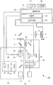
本実施形態に係るレーザ顕微鏡100は、図1に示すように、標本Sが載置されるステージ1と、レーザ光を発するレーザ光源部(レーザ光源)10と、標本Sを光刺激する刺激光学系20と、標本Sを観察する観察光学系30と、刺激光学系20の光路(刺激光路)と観察光学系30の光路(観察光路)とを合成するダイクロイックミラー等の光路合成部3と、標本Sにレーザ光を照射する一方、標本Sからの戻り光を集光する対物レンズ5と、制御装置50と、モニタ57と、キーボード等の入力装置59とを備えている。同図において、符合7は結像レンズを示し、符合9はミラーを示している。
[First Embodiment]
A laser microscope according to a first embodiment of the present invention will be described below with reference to the drawings.
As shown in FIG. 1, a
ステージ1は、対物レンズ5の光軸方向に移動可能に設けられており、制御装置50に接続されている。このステージ1は制御装置50により制御されるようになっている。また、ステージ1の光軸方向における位置情報が制御装置50に送られるようになっている。
The stage 1 is provided so as to be movable in the optical axis direction of the
レーザ光源部10は、標本Sを刺激するためのレーザ光(以下、刺激光という。)を発するレーザ光源11と、標本Sを励起して蛍光を発生させるためのレーザ光(以下、励起光という。)を発するレーザ光源13とを備えている。レーザ光源11は刺激光学系20に配置され、レーザ光源13は観察光学系30に配置されている。
The laser
刺激光学系20は、レーザ光源11から発せられた刺激光の光束径を調節可能なビームエキスパンダ21と、刺激光を反射する直角プリズム23と、刺激光の位相を変調可能な空間光位相変調器(位相変調型の空間光変調器。Liquid Crystal On Silicon−Spatial Light Modulator。以下、「LCOS−SLM」という。)25と、LCOS−SLM25により位相を調節された刺激光を反射するミラー27と、ミラー27により反射された刺激光を光路合成部3に入射させて、結像レンズ7の手前で像を結ばせるリレーレンズである瞳投影レンズ29とを備えている。
The stimulation
レーザ光源11としては、例えば、赤外線領域の超短パルスレーザ光(刺激光)を射出する赤外パルスレーザを採用することができる。
直角プリズム23は、レーザ光源11から発せられビームエキスパンダ21を介して入射される刺激光をLCOS−SLM25に向けて反射する一方、LCOS−SLM25から戻る刺激光をミラー27に向けて反射することができるようになっている。
As the
The right-
LCOS−SLM25は、対物レンズ5の瞳位置と共役な位置に配置されており、制御装置50に接続されている。このLCOS−SLM25は、制御装置50により制御され、入射した刺激光の波面形状を位相変調により変化させて反射するようになっている。これにより、LCOS−SLM25は、標本S上での刺激光の強度分布を3次元的に変化させて、標本Sに所望の3次元的なパターンの刺激光を照射することができるようになっている。
The LCOS-
3次元的なパターンは、刺激光の光軸方向の位置が異なる2箇所以上のスポットを含むこととする。これにより、例えば、標本S上の一点に刺激光を照射したり、標本S上のXYZ軸方向にわたる3次元的な多点に刺激光を同時に照射したりすることができるようになっている。 The three-dimensional pattern includes two or more spots having different positions in the optical axis direction of the stimulation light. Thereby, for example, one point on the sample S can be irradiated with the stimulation light, or the three-dimensional multipoints on the sample S extending in the XYZ axis directions can be irradiated with the stimulation light at the same time.
観察光学系30は、レーザ光源13から発せられた励起光を透過する一方、標本Sにおいて発生した蛍光を反射する特性を有するダイクロイックミラー31と、標本S上で励起光を走査させるガルバノミラー(走査部)33と、ガルバノミラー33により走査された励起光を光路合成部3に入射させて、結像レンズ7の手前で像を結ばせるリレーレンズである瞳投影レンズ35と、標本Sにおいて発生した蛍光を検出する検出光学系40とを備えている。
The observation
レーザ光源13は、例えば、レーザ光源11とは異なる波長の可視レーザ光を励起光として射出するようになっている。
ガルバノミラー33は、制御装置50に接続されている。また、ガルバノミラー33は、光軸に対して互いに垂直な揺動軸回りに揺動可能な一対のミラー対(図示略)を備えている。このガルバノミラー33は、制御装置50により制御されて、ミラー対を揺動させながら励起光を反射することにより、標本S上で励起光をXY方向に走査させることができるようになっている。
For example, the
The galvanometer mirror 33 is connected to the
また、ガルバノミラー33は、ミラー対の揺動角度信号を制御装置50へ出力するようになっている。また、ガルバノミラー33は、対物レンズ5の瞳位置と光学的に共役な位置に配置されていることが望ましい。
Further, the galvanometer mirror 33 outputs a swing angle signal of the mirror pair to the
検出光学系40は、ダイクロイックミラー31により反射された蛍光を集光する共焦点レンズ41と、共焦点レンズ41により集光された蛍光の光束を制限する共焦点ピンホール43と、共焦点ピンホール43を通過した蛍光を平行光にするコリメートレンズ45と、平行光になった蛍光の強度を検出するPMT(Photo Multiplier Tube、検出部。)47とを備えている。
The detection
共焦点ピンホール43は、標本の観察面と共役な位置に配置されており、観察面から発生した蛍光のみを通過させ、それ以外の層から発生した蛍光を除去することができるようになっている。
PMT47は、検出した蛍光の検出信号を制御装置50に出力するようになっている。このPMT47は、対物レンズ5の瞳位置と光学的に共役な位置に配置されていることが望ましい。
The
The
制御装置50は、観察光学系30による励起光の照射位置と刺激光学系20による刺激光の照射位置とを対応付ける相関補正部51と、刺激光学系20および観察光学系30の制御および標本Sの画像処理等を行う制御部(画像構築部、位置設定部)53と、対物レンズ5の収差を補正する収差補正部55とを備えている。
The
相関補正部51は、LCOS−SLM25により位相が調節された刺激光学系20の刺激光が照射される標本Sの画像のパターンとガルバノミラー33により走査された観察光学系30の励起光が照射される標本Sの画像のパターンとが略一致するように、LCOS−SLM25による刺激光の位相変調を制御するようになっている。
The
制御部53は、LCOS−SLM25のリフレッシュタイミングとガルバノミラー33およびPMT47の制御とを同期させて、観察光学系30により励起光を照射する標本Sの画像の取得と刺激光学系20により刺激光を照射する標本Sの光刺激のタイミングとを制御するようになっている。
The
また、制御部53は、ステージ1から送られてくるステージの光軸方向における位置情報と、ガルバノミラー33から送られてくるミラー対の揺動角度信号と、PMT47から送られてくる蛍光の検出信号とに基づいて、ガルバノミラー33による励起光の走査とPMT47による蛍光の検出とを同期させて、標本Sの3次元的な画像を構築することができるようになっている。
Further, the
さらに、制御部53は、構築した標本Sの画像をモニタ57に表示させることができるようになっている。そして、制御部53は、モニタ57に表示した標本Sの3次元的な画像上において、ユーザにより入力装置59を介して入力される刺激光学系20によって光刺激する標本Sの刺激箇所、すなわち、刺激光の照射位置を光軸方向に異なる複数個所に設定することができるようになっている。
Further, the
収差補正部55には、設計上や製造上の誤差に起因する対物レンズ5の収差に関する収差データを対物レンズ5と対応づけて記憶させることができるようになっている。この収差補正部55は、対物レンズ5の収差データに基づき、その対物レンズ5の収差による影響を補正するように、LCOS−SLM25に入力する位相変調信号を生成するようになっている。
The
このように構成されたレーザ顕微鏡100の作用について説明する。
まず、本実施形態に係るレーザ顕微鏡100により標本Sを光刺激する場合について説明する。
刺激光学系20により標本Sを刺激するには、まず、レーザ光源11から刺激光を発生させ、ビームエキスパンダ21によりその光束径をLCOS−SLM25のサイズに合わせて調整する。ビームエキスパンダ21により光束径が調整された刺激光は、直角プリズム23により反射されて、平行光としてLCOS−SLM25に入射される。
The operation of the
First, the case where the sample S is optically stimulated by the
In order to stimulate the specimen S with the stimulation
LCOS−SLM25に入射された刺激光は、位相が変調されて波面形状が変化して直角プリズム23に戻される。直角プリズム23に戻された刺激光は、ミラー27に向けて反射され、瞳投影レンズ29を介して光路合成部3に入射される。光路合成部3に入射された刺激光は、反射されて観察光学系30との共通の光路を進み、結像レンズ7およびミラー9を介して対物レンズ5に入射される。
The stimulus light incident on the LCOS-
対物レンズ5に入射された刺激光は、LCOS−SLM25による位相変調によって形成された所望のパターンで標本Sに照射される。これにより、刺激光の照射パターンに従い標本Sが刺激される。
The stimulus light incident on the
次に、本実施形態に係るレーザ顕微鏡100により標本Sを観察する場合について説明する。
観察光学系30により標本Sを観察するには、まず、レーザ光源13から励起光を発生させ、ダイクロイックミラー31を透過させてガルバノミラー33に入射させる。ガルバノミラー33に入射された励起光は、ミラー対により標本S上の走査位置に応じた方向に偏向され、瞳投影レンズ35を介して光路合成部3に入射される。
Next, the case where the sample S is observed with the
In order to observe the sample S with the observation
光路合成部3に入射した励起光は、透過して刺激光学系20との共通の光路を通り、結像レンズ7およびミラー9を介して対物レンズ5により標本に照射される。これにより、ガルバノミラー33のミラー対の揺動角度に応じて、標本S上で励起光が走査される。
The excitation light incident on the optical
励起光が照射されることにより標本S上の走査位置において蛍光が発生すると、蛍光は対物レンズ5により集光され、ミラー9、結像レンズ7、光路合成部3、瞳投影レンズ35、および、ガルバノミラー33を介して励起光の光路を戻り、ダイクロイックミラー31により反射されて検出光学系40に入射される。
When fluorescence is generated at the scanning position on the specimen S by being irradiated with the excitation light, the fluorescence is collected by the
検出光学系40に入射した蛍光は、共焦点レンズ41により集光されて共焦点ピンホール43によりその光束径が制限された後、コリメートレンズ45により平行光にされてPMT47によりその強度が検出される。PMT47により蛍光の強度が検出されると、その蛍光の検出信号がガルバノミラー33のミラー対の揺動角度信号と共に制御装置50に送られる。さらに、ステージ1から送られてくるステージ1の光軸方向における位置情報が制御装置50に送られる。制御部53において、これらの蛍光の検出信号、ミラー対の揺動角度信号およびステージ1の光軸方向における位置情報に基づいて、標本Sの3次元的な画像が構築される。
The fluorescence that has entered the detection
次に、これらの刺激光学系20による標本Sの光刺激と観察光学系30による標本Sの観察とを光照射位置のズレが少なくなるように対応付けて行う場合について説明する。
刺激光学系20による標本Sの光刺激と観察光学系30による標本Sの観察とを対応付けて行うには、まず、ステージ1上の標本位置上にミラー(図示略。以下、「ミラー標本」という。)を載置し、刺激光学系20により、レーザ光源11から刺激光を発生させてLCOS−SLM25によって位相変調し、規定パターンからなるグリッドをミラー標本上に照射する。
Next, the case where the optical stimulation of the specimen S by the stimulation
In order to associate the optical stimulation of the specimen S by the stimulation
この状態で、観察光学系30により、励起光を発生させずに、標本S上を走査するのと同様にミラー対を揺動させてミラー標本を空スキャンし、制御部53により、刺激光が照射された標本Sの画像を取得する。そして、制御部53によって構築される標本Sの画像のパターンが規定パターンに一致するように、すなわち、標本Sの画像における照射パターンと規定の照射パターンとの差分が相殺されるように、相関補正部51によりLCOS−SLM25の位相変調が制御される。また、規定パターンに一致したときの位相変調設定が相関補正部51に記憶される。
In this state, the observation
これにより、観察光学系30による励起光のXY軸方向の照射位置と刺激光学系20による刺激光のXY軸方向の照射位置とが対応付けられる。
観察光学系30による励起光のZ軸方向の照射位置と刺激光学系20による刺激光のZ軸方向の照射位置との関連付けはオープンループ制御とする。ここでいうオープンループ制御とは、実際の画像との差分を補正に利用するのではなく、設計的に求められる波面変調の値を用いた制御である。
Thereby, the irradiation position of the excitation light by the observation
The association between the irradiation position of the excitation light in the Z-axis direction by the observation
次に、ステージ1に標本Sを載置し、観察光学系30により、レーザ光源13から励起光を発生させてガルバノミラー33により標本S上で走査させる。そして、2次元平面上を走査し終える毎にステージ1を光軸方向へ移動させ、PMT47および制御部53により標本SのXYZスタック画像を構築する。そして、制御部53により、3次元画像化ソフトを用いて、XYZスタック画像から3次元的な画像(以下、3次元画像という。)に変換する。
Next, the specimen S is placed on the stage 1, the excitation light is generated from the
次いで、モニタ57に標本Sの3次元画像を表示し、画像操作手段(図示略)により、3次元画像を拡大、縮小、回転、移動等の操作をして、標本Sの刺激箇所を2箇所以上探す。この際、3次元画像を半透明で表示して内部構造を視認可能にしたり、3次元画像を任意の位置でスライスして表示して注目部位を探しやすくしたりしてもよい。
Next, a three-dimensional image of the sample S is displayed on the
このような操作により探した標本Sの刺激箇所は、ユーザにより入力装置59を介して入力され、制御部53により標本Sの3次元画像上において設定される。続いて、制御部53により、設定した刺激箇所から標本Sの3次元的な座標が算出され、算出された座標データが収差補正部55へ出力される。そして、収差補正部55により、制御部53から送られてきた座標データに基づいてその座標位置に刺激光を照射するための位相変調信号が生成されて、LCOS−SLM25に送られる。これにより、LCOS−SLM25による刺激光の位相変調が制御される。
The stimulation location of the sample S searched for by such an operation is input by the user via the
この場合において、収差補正部55に対物レンズ5とその収差データを対応づけて記憶させておくことで、収差補正部55により、刺激光が対物レンズ5から受ける収差をキャンセルする波面となるような位相変調信号が生成される。これにより、対物レンズ5により受ける収差の影響を補正することができる。
In this case, the
したがって、刺激光学系20において、レーザ光源11から刺激光を発生させると、LCOS−SLM25により、観察光学系30によって取得された標本Sの3次元画像上で設定された所望の複数の刺激箇所に応じたパターンが形成され、各刺激箇所に同時に刺激光が照射される。これにより、標本Sの複数の刺激箇所を同時に刺激しながら、観察光学系30によって取得される標本Sの3次元画像でその反応を観察することができる。
Therefore, when stimulation light is generated from the
以上説明したように本実施形態に係るレーザ顕微鏡100によれば、観察光学系30により取得される標本Sの3次元画像上において、刺激光学系20により刺激する標本Sの刺激箇所を設定することで、刺激箇所の設定を容易にすることができる。また、LCOS−SLM25による刺激光の位相変調によって観察光学系30による励起光の照射位置と刺激光学系20による刺激光の照射位置とを対応付けることで、観察光学系30により取得される標本Sの3次元画像上において設定される所望の複数の刺激箇所に対して、刺激光学系20により同時に刺激光を照射することができる。
As described above, according to the
特に、ステージ1を光軸方向に移動させて、刺激光学系20により照射する刺激光の標本Sにおける深さ位置と観察光学系30により励起光が照射された標本Sの3次元的な画像上の深さ位置とを対応付けることで、標本Sの同一箇所を刺激しながら、観察光学系30による観察位置の深さを変えた観察を同時に行うことができる。したがって、標本Sの複数の刺激箇所を簡便に設定して、各刺激箇所を同時に光刺激することができる。
In particular, when the stage 1 is moved in the optical axis direction, the depth position of the stimulation light irradiated by the stimulation
また、収差補正部55により、対物レンズ5の収差の影響を補正することで、複数の刺激箇所に精度よく刺激光を照射することができる。さらに、観察光学系30の光路と刺激光学系20の光路とを別々に設けることで、観察光学系30による励起光の照射と刺激光学系20による刺激光の照射とを同時に行い、標本Sの刺激とその反応の観察とをタイムラグ無く行うことができる。
In addition, by correcting the influence of the aberration of the
本実施形態においては、3次元画像化ソフトを用いて、XYZスタック画像から3次元画像に変換してから刺激箇所を設定することとしたが、例えば、観察光学系30により取得されるXY2次元画像をモニタ(図示略)に表示し、Z軸方向の位置を変えながら刺激したい部分を探して、制御部53により2次元画像上において刺激箇所を設定することとしてもよい。
In the present embodiment, the stimulus location is set after converting the XYZ stack image into the three-dimensional image using the three-dimensional imaging software. For example, the XY two-dimensional image acquired by the observation
また、本実施形態においては、収差補正部55により対物レンズ5の収差を補正することとしたが、対物レンズ5の収差のみならず、直角プリズム23、ミラー27、瞳投影レンズ29、光路合成部3、結像レンズ7、ミラー9等の顕微鏡光学系の収差や標本Sの屈折率ミスマッチも補正することとしてもよい。
In the present embodiment, the
また、本実施形態においては、3次元画像を取得する際に、2次元平面上を走査し終える毎にステージ1を光軸方向へ移動させることとしたが、ステージ1を固定するものとし、その代わりに制御装置50により対物レンズ5を制御して、2次元平面上を走査し終える毎に対物レンズ5を光軸方向へ移動させることとしてもよい。
In this embodiment, when acquiring a three-dimensional image, the stage 1 is moved in the direction of the optical axis every time scanning on the two-dimensional plane is completed. Alternatively, the
〔第2実施形態〕
次に、本発明の第2実施形態に係るレーザ顕微鏡について説明する。
本実施形態に係るレーザ顕微鏡200は、図2に示すように、レーザ光源部10がレーザ光源11に代えてレーザ光源装置110を備え、刺激光学系20により照射する刺激光の強度を設定する強度設定部157と、CCDカメラ(標本画像取得部)161と、CCDカメラ161の前段に配置される結像レンズ163と、ミラー9に代えて配置されるハーフミラー109とを備える点で、第1実施形態と異なる。
以下、第1実施形態に係るレーザ顕微鏡100と構成を共通する箇所には、同一符号を付して説明を省略する。
[Second Embodiment]
Next, a laser microscope according to the second embodiment of the present invention will be described.
In the
In the following, portions having the same configuration as those of the
レーザ光源装置110は、異なる波長の可視レーザ光(刺激光)を発生する複数のレーザ光源111A,111B,111Cと、これらのレーザ光源111A,111B,111Cから発せられた各刺激光を同一光路に統合するミラー113A,113Bおよびダイクロイックミラー114A,114Bと、同一光路に統合された各刺激光のパワーを調整可能なAOTF(Acoust Optic Tunable Filter:音響光学可変フィルター)115と、各波長の刺激光を集光するカップリングレンズ117とを備えている。
The laser
また、レーザ光源装置110には、カップリングレンズ117により集光された刺激光を刺激光学系20に導光するシングルモードファイバ118と、シングルモードファイバ118により導光された刺激光を平行光にしてビームエキスパンダ21に入射させるコリメートレンズ119とが備えられている。
The laser
レーザ光源111Aから発せられた刺激光は、ダイクロイックミラー114Aにより反射されてミラー113Aを介してAOTF115に入射されるようになっている。また、レーザ光源111Bから発せられた刺激光は、ダイクロイックミラー114Bにより反射された後、ダイクロイックミラー114Aを透過してミラー113Aを介してAOTF115に入射されるようになっている。さらに、レーザ光源111Cから発せられた刺激光は、ミラー113Bにより反射された後、ダイクロイックミラー114B,114Aを透過してミラー113Aを介してAOTF115に入射されるようになっている。
AOTF115は、強度設定部157により、透過させる刺激光の光量および波長を選択することができるようになっている。
The stimulation light emitted from the
In the
入力装置59は、ユーザにより操作され、モニタ57に表示される標本Sの3次元画像上において制御部53により設定される刺激箇所に対して、所望の刺激強度および刺激時間を入力することができるようになっている。また、入力装置59には、刺激光学系20により標本Sを刺激する刺激箇所と、観察光学系30による標本Sを観察する観察範囲を設定することができるようになっている。
The
強度設定部157は、入力装置59により入力された刺激箇所ごとの刺激強度および刺激時間に従い、レーザ光源装置110を制御するようになっている。これにより、標本Sの各刺激箇所に対して、刺激時間を異ならせつつ、相対的な強度比率で刺激光を照射したり同一の刺激強度で刺激光を照射したりすることができるようになっている。
The
ハーフミラー109は、励起光が照射されることにより標本Sにおいて発生し対物レンズ5により集光されて励起光の光路を戻る蛍光を結像レンズ7に向けて反射する一方、刺激光が照射されることにより標本Sにおいて反射されてその刺激光の光路を戻る反射光を透過させるようになっている。
The
CCDカメラ161と結像レンズ163は、対物レンズ5と光路合成部3との間に配置されており、ハーフミラー109を透過した反射光が結像レンズ163により集光されてCCDカメラ161により撮影されるようになっている。
The
このように構成された本実施形態に係るレーザ顕微鏡200の作用について説明する。
本実施形態は、相関補正部51によりLCOS−SLM25の位相変調を行う相関補正用の画像をCCDカメラ161により取得する点で、観察光学系30のガルバノミラー33を空スキャンさせて画像を取得する第1実施形態と異なる。具体的には、本実施形態に係るレーザ顕微鏡200により刺激光学系20による標本Sの光刺激と観察光学系30による標本Sの観察とを対応付けて行うには、予め、CCDカメラ161の各画素と観察光学系30の走査側の各画素とを対応付けておく。
The operation of the
In the present embodiment, the
そして、第1実施形態と同様に、ステージ1にミラー標本を載置し、レーザ光源装置110から刺激光を発生させて、規定パターンからなるグリッドをミラー標本上に照射する。ミラー標本に照射された刺激光は反射されて光路を逆方向に戻り、対物レンズ5により集光されてハーフミラー109を透過し、結像レンズ7を介してCCDカメラ161に入射される。これにより、CCD161の受光面において規定パターンのグリッドが投影され、CCDカメラ161によって刺激光のグリッドの画像が取得される。
Then, as in the first embodiment, a mirror sample is placed on the stage 1, stimulation light is generated from the laser
次いで、相関補正部51により、CCDカメラ161によって取得される標本Sの画像のパターンが規定パターンに一致するように、LCOS−SLM25による位相変調が制御される。また、規定パターンに一致したときの位相変調設定が相関補正部51に記憶される。
Next, the phase correction by the LCOS-
これにより、観察光学系30による励起光のXY軸方向の照射位置と刺激光学系20による刺激光のXY軸方向の照射位置とが対応付けられる。したがって、制御部53により、観察光学系30によって取得される標本Sの3次元画像において刺激箇所を設定することで、刺激光学系20によりその刺激箇所に刺激光を同時に照射することができる。
Thereby, the irradiation position of the excitation light by the observation
ここで、観察光学系30により観察する範囲の深さを変えるには、標本Sが載置されたステージ1または対物レンズ5を光軸方向に動かすことになる。そうすると、刺激光学系20により標本Sに照射される刺激光の照射位置がステージ1または対物レンズ5の移動量に応じて変動してしまう。したがって、刺激位置を標本S内の当初設定した位置に保ったまま3次元画像を取得するには、LCOS−SLM25により、ステージ1または対物レンズ5の移動量に応じた量だけ刺激光に位相変調を加えることで刺激位置を戻せばよい。
Here, in order to change the depth of the range observed by the observation
本実施形態においては、入力装置59により、刺激光学系20による標本Sの刺激位置と観察光学系30による標本Sの観察範囲(XYZ範囲とスライス幅)を設定しておくことで、相関補正部51により、LCOS−SLM25による位相変調が制御されて、刺激光の照射位置が一定に保たれる。
In the present embodiment, the correlation correction unit is set by setting the stimulation position of the specimen S by the stimulation
具体的には、刺激光学系20により標本Sに刺激光を照射するとともに観察光学系30により標本SのXY軸方向の画像を取得しつつ、スライス幅の分だけZ軸方向の位置を変更すると、入力装置59により入力された刺激光学系20による標本Sの刺激位置と観察光学系30による標本Sの観察範囲とに基づいて、相関補正部51によりLCOS−SLM25が制御され、位相変調により刺激光の照射位置の深さがスライス幅の分だけ元の深さに戻される。これにより、刺激位置が一定に保たれる。続いて、観察光学系30により2枚目のXY画像が取得され、最初に設定されたZ位置まで同様の手順が繰り返される。
Specifically, when the stimulus
このようにすることで、観察光学系30により観察する深さを変えても、刺激光学系20により標本Sに照射される刺激光の照射位置が変動してしまうのを防ぎ、常に標本Sの同一箇所を刺激することができる。
By doing so, even if the depth of observation by the observation
次に、強度設定部157により、刺激光学系20によって光刺激する標本Sの刺激箇所ごとに異なる刺激強度または異なる照射時間で刺激光を照射する場合について説明する。なお、設定できる刺激強度は刺激箇所の数で決まり、10箇所であれば1つの刺激箇所に対する刺激強度は最大でレーザ光源装置110の最大出力の10%であり、3箇所であれば1つの刺激箇所に対する刺激強度は最大でレーザ光源装置110の最大出力の33%である。
Next, a case will be described in which the
まず、各刺激箇所に対して相対的な強度比率で刺激光を照射する場合は、例えば、3箇所を刺激することとすると、刺激強度がトータルで100%になるように、例えば、入力装置59により各刺激箇所についてそれぞれレーザ光源装置110の最大出力の20%、30%、50%に設定する。また、刺激時間は、例えば、各刺激箇所についてそれぞれ1秒、3秒、5秒に設定する。
First, when irradiating stimulation light at a relative intensity ratio with respect to each stimulation location, for example, when 3 locations are stimulated, for example, the
このように設定した場合は、相関補正部51により、設定した各刺激位置に対して相対的な強度比率でスポットが結ばれるようにLCOS−SLM25による刺激光の位相変調が制御され、強度設定部157により、レーザ光源装置110が以下のように制御される。
When set in this way, the
まず、刺激開始から1秒後に、20%に設定した刺激箇所への照射が終了される。そして、AOTF115の透過率が初期の透過率に対して20%低減される。次いで、刺激開始から3秒後に、30%に設定した刺激箇所への照射が終了される。そして、AOTF115の透過率が初期の透過率に対して50%低減される。次いで、刺激開始から5秒後に、50%に設定した刺激箇所への照射も終了される。
First, after 1 second from the start of stimulation, irradiation to the stimulation location set to 20% is completed. Then, the transmittance of the
これにより、刺激箇所ごとに異なる強度で刺激光を照射するともに、刺激箇所ごとに刺激を加える時間を変えることができる。
なお、AOTF115の透過率を予め所望の値まで下げてから実行するようにしてもよい。このようにすることで、標本Sへのダメージを低減することが可能になる。
Thereby, while irradiating stimulation light with different intensity | strength for every irritation | stimulation location, the time which applies irritation | stimulation for every irritation | stimulation location can be changed.
Note that the
一方、標本Sの各刺激箇所に対して同じ強度で刺激光を照射する場合は、例えば、刺激箇所を3箇所とすると、例えば、入力装置59により各刺激箇所に対してレーザ光源装置110の最大出力の33%に設定する。この場合も、刺激箇所ごとに刺激時間を設定することとしてもよい。例えば、刺激箇所ごとに刺激時間をそれぞれ1秒、3秒、5秒に設定する。
On the other hand, when irradiating stimulation light with the same intensity with respect to each stimulation location of the sample S, for example, if the stimulation location is 3 locations, for example, the maximum of the laser
このように設定した場合は、相関補正部51により、設定した各刺激位置に対して同じ刺激強度でスポットが結ばれるようにLCOS−SLM25による刺激光の位相変調が制御され、強度設定部157により、レーザ光源装置110が以下のように制御される。
In this case, the
まず、刺激開始から1秒後に1つ目の刺激箇所への照射が終了される。そして、AOTF115の透過率が初期の透過率に対して66%に低減される。次いで、刺激開始から3秒後に2つ目の刺激箇所への照射が終了される。そして、AOTF115の透過率が初期の透過率に対して33%に低減される。次いで、刺激開始から5秒後に3つ目の刺激箇所への照射も終了される。これにより、刺激箇所ごとに同じ強度で刺激光を照射するともに、刺激箇所ごとに刺激を加える時間を変えることができる。
First, the irradiation to the first stimulation location is completed after 1 second from the start of stimulation. Then, the transmittance of the
以上説明したように、本実施形態に係るレーザ顕微鏡200によれば、CCD161により、刺激光学系20によって刺激光を照射した標本Sの画像を簡易に取得することができる。したがって、CCD161により取得される刺激光を照射した標本Sの画像上での刺激光の強度分布のパターンに基づいて、LCOS−SLM25による刺激光の位相の変調を行うことで、刺激光学系20により標本Sに照射する刺激光を規定の強度分布のパターンに簡易かつ迅速に設定することができる。また、強度設定部157により、標本Sの刺激する刺激箇所ごとに刺激光の強度を設定し、刺激光強度と標本Sの反応とを関連付けて観察することができる。
As described above, according to the
また、刺激光学系20により照射する刺激光の標本Sにおける深さ位置と観察光学系30により励起光が照射された標本Sの3次元的な画像上の深さ位置とを対応付けることで、標本Sの同一箇所を刺激しながら、観察光学系30による観察位置の深さを変えた観察を同時に行うことができる。
In addition, by associating the depth position in the sample S of the stimulation light irradiated by the stimulation
本実施形態においては、観察光学系30により励起光を照射した標本SをCCD161により観察することとしてもよい。このようにすることで、PMT47および制御部53により画像を構築する場合と比較して、標本Sにおける刺激後の動態を高速に画像化することができる。
In the present embodiment, the specimen S irradiated with the excitation light by the observation
ここで、標本Sの深さが異なる複数の刺激箇所を同一強度で刺激しようとすると、標本Sでの散乱や吸収により、深い位置の刺激強度は浅い位置よりも弱くなる傾向がある。そこで、例えば、標本S上での散乱や減光の影響を考慮して、深さが異なる複数の刺激箇所を同一強度で刺激することとしてもよい。 Here, when a plurality of stimulation locations having different depths of the specimen S are to be stimulated with the same intensity, the stimulation intensity at a deep position tends to be weaker than that at a shallow position due to scattering and absorption in the specimen S. Therefore, for example, in consideration of the influence of scattering and dimming on the specimen S, a plurality of stimulation locations having different depths may be stimulated with the same intensity.
この場合、例えば、強度設定部157が、標本Sにおいて照射された刺激光が減光する減光関数を記憶する記憶部(図示略)と、記憶部に記憶されている減光関数に基づいてレーザ光源装置110の出力を調節する出力調節部(図示略)とを備えることとしてもよい。
In this case, for example, the
そして、記憶部には、減光関数として、例えば、標本Sの散乱係数と吸収係数が記憶されることとしてもよい。
また、出力調節部は、各刺激箇所の3次元座標と、記憶部に記憶されている標本Sの散乱係数および吸収係数とから、刺激強度の基準にする刺激箇所(以下、基準刺激箇所という。)と同じ強度で刺激光が照射されるような刺激強度を刺激箇所ごとに算出することとしてもよい。さらに、出力調節部により算出された刺激箇所ごとの刺激強度が収差補正部55に送られることとしてもよい。なお、出力調節部は、必要に応じて、AOTF115の透過率を上げることとしてもよい。
The storage unit may store, for example, the scattering coefficient and the absorption coefficient of the sample S as a dimming function.
In addition, the output adjustment unit uses the three-dimensional coordinates of each stimulation point and the scattering coefficient and absorption coefficient of the sample S stored in the storage unit as a reference for the stimulation intensity (hereinafter referred to as a reference stimulation point). ), The stimulation intensity at which the stimulation light is irradiated with the same intensity may be calculated for each stimulation location. Furthermore, the stimulation intensity for each stimulation location calculated by the output adjustment unit may be sent to the
本変形例に係るレーザ顕微鏡200により、深さが異なる複数の刺激箇所を同一強度で刺激するには、まず、標本Sの散乱係数と吸収係数を予め記憶部に記憶させておき、入力装置59により、各刺激箇所の刺激強度をパーセンテージで設定する。例えば、全ての刺激箇所に対してレーザ光源装置110の最大出力の10%の刺激強度で刺激光を照射するように設定すればよい。また、基準刺激箇所を選択する。
In order to stimulate a plurality of stimulation locations having different depths with the same intensity using the
出力調節部により、各刺激箇所の3次元座標と、記憶部に記憶されている標本Sの散乱係数および吸収係数とから、刺激箇所ごとに基準刺激箇所と同じ強度で刺激光を照射可能な刺激強度が算出されて収差補正部55に送られる。そして、収差補正部55により、入力された刺激箇所ごとの刺激強度に応じた位相変調信号が生成され、LCOS−SLM25に送られて位相変調が制御される。また、出力調節部により、必要に応じて、AOTF115の透過率が上げられる。これにより、LCOS−SLM25により刺激光の位相が変調されて、標本Sの複数の刺激箇所に深さに応じた強度で刺激光が照射される。
Stimulus capable of irradiating stimulation light at the same intensity as the reference stimulation location for each stimulation location from the three-dimensional coordinates of each stimulation location and the scattering coefficient and absorption coefficient of the sample S stored in the storage unit by the output adjustment unit The intensity is calculated and sent to the
このようにすることで、標本Sの状態や種類によって減光関数の係数を修正するだけで、刺激光の照射位置の深さに関わらず一定の強度で標本Sを刺激するように、刺激光の強度を容易に調節することができる。また、ユーザは散乱による刺激光の減光を意識せずに、各刺激箇所に対して同じ強度で刺激を行うことができる。 In this way, the stimulating light can be stimulated so that the sample S is stimulated at a constant intensity regardless of the depth of the irradiation position of the stimulating light by simply correcting the coefficient of the dimming function according to the state and type of the sample S. Can be easily adjusted. In addition, the user can perform stimulation at the same intensity for each stimulation location without being conscious of dimming of the stimulation light due to scattering.
本変形例においては、記憶部が標本Sの深さに対する刺激光の散乱率および吸収率に関するテーブルを記憶し、出力調節部が記憶部に記憶されているテーブルに基づいてレーザ光源装置110の出力を調節することとしてもよい。
この場合、標本Sの深さごとの散乱率と吸収率のテーブルを予め記憶部に記憶させておくこととすればよい。
In this modification, the storage unit stores a table relating to the scattering rate and absorption rate of the stimulation light with respect to the depth of the sample S, and the output adjustment unit outputs the output of the laser
In this case, a table of scattering rate and absorption rate for each depth of the sample S may be stored in the storage unit in advance.
そして、出力調節部により、各刺激箇所の3次元座標と記憶部に記憶されているテーブルとから、刺激箇所ごとに基準刺激箇所と同じ強度で刺激光を照射可能な刺激強度を算出するとともに、必要に応じてAOTF115の透過率を上げることとすればよい。そして、収差補正部55により、その刺激箇所ごとの刺激強度に応じた位相変調信号を生成して、LCOS−SLM25による位相変調を制御することとすればよい。
And by the output adjustment unit, from the three-dimensional coordinates of each stimulation location and the table stored in the storage unit, for each stimulation location, to calculate the stimulation intensity that can irradiate the stimulation light with the same intensity as the reference stimulation location, What is necessary is just to raise the transmittance | permeability of AOTF115 as needed. Then, the
このようにすることで、同じ標本Sを観察し続けるような場合において、正確かつ容易にテーブルを作成することができる。また、関数化するのが困難な場合に有効である。 By doing so, the table can be created accurately and easily in the case where the same specimen S is continuously observed. It is also effective when it is difficult to make a function.
また、本実施形態においては、相関補正部51が、刺激光の波長ごとに、観察光学系30による励起光の照射位置と刺激光学系20による刺激光の照射位置とを対応付けた相関テーブルを有することとしてもよい。この場合、入力装置59により標本Sに照射する刺激光の波長を選択した段階で、相関補正部51により相関テーブルから刺激光の波長に対応した位相変調値を算出して、収差補正部55に送ることとすればよい。
Moreover, in this embodiment, the correlation correction |
このようにすることで、標本Sを刺激する刺激光の波長に応じた最適な変調を行うことができる。したがって、刺激光の波長が変わっても、観察光学系30により取得される標本Sの3次画像上において、狙った位置へ刺激光を照射することができる。
By doing in this way, the optimal modulation | alteration according to the wavelength of the stimulus light which stimulates the sample S can be performed. Therefore, even if the wavelength of the stimulation light changes, it is possible to irradiate the target position on the tertiary image of the sample S acquired by the observation
本実施形態は、観察光学系30の光路と刺激光学系20の光路とを別個に設けることとしたが、これに代えて、例えば、図3および図4に示すように、観察光学系30の光路と刺激光学系20の光路とを共通にすることとしてもよい。
In the present embodiment, the optical path of the observation
具体的には、図3に示すように、レーザ顕微鏡200が、レーザ光源部10に代えて、レーザ光を発振するレーザ光源112を備えることとしてもよい。そして、観察光学系および刺激光学系を、ビームエキスパンダ21と、直角プリズム23と、LCOS−SLM25と、直角プリズム23により再度反射されたレーザ光をリレーするリレー光学系126と、ダイクロイックミラー31と、ガルバノミラー33と、瞳投影レンズ35と、検出光学系40とにより構成することとしてもよい。この場合、標本Sを観察する場合は、レーザ光の光路プリズム23を脱離するか、または、LCOS−SLM25による位相変調を行わないように制御することとすればよい。
Specifically, as shown in FIG. 3, the
また、図4に示すように、レーザ顕微鏡200が、レーザ光源部10に代えて、標本Sに多光子励起を生じさせるIRパルスレーザを発振するレーザ光源114を備えることとしてもよい。そして、観察光学系および刺激光学系を、ビームエキスパンダ21と、直角プリズム23と、LCOS−SLM25と、直角プリズム23により再度反射されたレーザ光をリレーするリレー光学系126と、ガルバノミラー33と、瞳投影レンズ35とにより構成することとしてもよい。さらに、レーザ顕微鏡200が、標本Sからの蛍光を反射するダイクロイックミラー171と、ダイクロイックミラー171により反射された蛍光を集光する集光レンズ172と、集光レンズ172により集光された蛍光を検出するPMT175とを備えることとしてもよい。この場合も同様に、標本Sを観察する場合は、レーザ光の光路プリズム23を脱離するか、または、LCOS−SLM25による位相変調を行わないように制御することとすればよい。
As shown in FIG. 4, the
〔第3実施形態〕
次に、本発明の第3実施形態に係るレーザ顕微鏡について説明する。
本実施形態に係るレーザ顕微鏡300は、図5に示すように、レーザ光源部10に代えて、レーザ光を発するレーザ光源211,213を有するレーザ光源部210を備え、さらに、レーザ光源211,213から発せられるレーザ光の透過率を制御するAOM(Acorstic Optical Modurator)215,217と、ミラー27に入射される刺激光を標本S上で走査させるガルバノミラー(刺激光走査部)226と、標本Sからの蛍光を反射するダイクロイックミラー171と、ダイクロイックミラー171により反射された蛍光から励起波長の光を除去するカットフィルタ173と、カットフィルタ173を通過した蛍光を検出するPMT175とを備える点で、第1実施形態および第2実施形態と異なる。
以下、第1実施形態に係るレーザ顕微鏡100または第2実施形態に係るレーザ顕微鏡200と構成を共通する箇所には、同一符号を付して説明を省略する。
[Third Embodiment]
Next, a laser microscope according to the third embodiment of the present invention will be described.
As shown in FIG. 5, the
In the following, portions having the same configuration as those of the
レーザ光源211,213は、それぞれ標本Sに多光子励起を生じさせるIRパルスレーザ(レーザ光)を発振するようになっている。
透過率を制御するためのAOM215、217は制御装置50と接続されている。
PMT47は制御部53に接続されている。
The
The
本実施形態においては、制御部53は、ガルバノミラー226の揺動角度とステージ1の位置とレーザ光の強度とに基づいて画像を構築することができるようになっている。
刺激光学系20によりXYZ軸方向に走査する深さの範囲は、予め厚さが正確に分かっている標本Sの底面から上面までとする。
In the present embodiment, the
The depth range scanned in the XYZ axis directions by the stimulation
また、本実施形態においては、相関補正部51は、LCOS−SLM25による位相変調によって刺激光学系20によるレーザ光の深さ方向の位置の目標値が標本Sの厚さと一致する制御値を算出して設定および記憶することができるようになっている。これにより、相関補正部51は、刺激光学系20によるレーザ光の深さ方向の位置と観察光学系30による観察範囲のZ軸方向の制御との相関をとることができるようになっている。
In the present embodiment, the
このように構成された本実施形態に係るレーザ顕微鏡300の作用について説明する。
レーザ光源211から発せられたレーザ光は、AOM215により透過率が制御された後、刺激光学系20のガルバノミラー226を介して光路合成部3により観察光学系30との共通の光路に入射される。また、レーザ光源213から発せられたレーザ光も、AOM217により透過率が制御された後、観察光学系30のガルバノミラー33を介して光路合成部3により刺激光学系20との共通の光路に入射される。
The operation of the
The laser light emitted from the
共通の光路に入射されたレーザ光は、それぞれハーフミラー109により反射された後、ダイクロイックミラー171を透過して対物レンズ5により標本Sに照射される。レーザ光が照射されることにより標本Sにおいて2光子の蛍光が発生すると、その蛍光は対物レンズ5により集光されて光路を逆方向に戻り、ダイクロイックミラー171により反射された後、カットフィルタ173を透過してPMT175により検出される。
The laser light incident on the common optical path is reflected by the
本実施形態においては、刺激光学系20によりレーザ光源211から発せられるレーザ光を標本Sに照射し、それにより標本Sにおいて発生する蛍光をPMT175により検出して、制御部53により標本のXYZ画像を構築する。ここで、XY軸方向はガルバノミラー226により走査し、Z軸方向のみLCOS−SLM25による位相変調によって動かす。このとき、多点照明はしない。つまり、LCOS−SLM25は、レーザ光の照射位置を光軸方向へ動かすことにのみ用いる。
In the present embodiment, the sample S is irradiated with laser light emitted from the
この場合において、相関補正部51により、LCOS−SLM25の位相変調によるレーザ光の深さ方向の位置の目標値が標本Sの厚さと一致する制御値が設定されて、観察光学系30によるZ軸方向の制御との相関がとられる。これにより、観察光学系30による観察範囲の深さ方向の移動とLCOS−SLM25の位相変調による刺激箇所の深さ方向の移動との対応を取ることができる。さらに、XY方向にガルバノミラー226を振りながらZ位置を動かすことによってXY方向の位置によらず正確にZ位置を補正することができる。
In this case, the
本実施形態においては、Z軸方向を補正することとしたが、これに代えて、例えば、各頂点に蛍光ビーズが付いた微細立方体の集合体など、形状および形態が3次元的に既知な標本(以下、3次元グリッド標本という。)を用いることとしてもよい。そして、LCOS−SLM25による位相変調よってレーザ光をXYZ軸方向に走査して多光子励起した3次元グリッド標本の3次元画像を取得することしてもよい。このようにすることで、LCOS−SLM25による位相変調の制御によってXYZ軸の3方向について補正ができる。
In the present embodiment, the Z-axis direction is corrected, but instead, for example, a specimen whose shape and form are known three-dimensionally, such as a collection of fine cubes with fluorescent beads at each vertex. (Hereinafter, referred to as a three-dimensional grid sample) may be used. And you may acquire the three-dimensional image of the three-dimensional grid sample which scanned the laser beam to the XYZ-axis direction by the phase modulation by LCOS-SLM25, and was excited by multiphoton. By doing so, the three directions of the XYZ axes can be corrected by controlling the phase modulation by the LCOS-
以上、本発明の実施形態について図面を参照して詳述してきたが、具体的な構成はこの実施形態に限られるものではなく、本発明の要旨を逸脱しない範囲の設計変更等も含まれる。例えば、本発明を上記の各実施形態に適用したものに限定されることなく、これらの実施形態を適宜組み合わせた実施形態に適用してもよく、特に限定されるものではない。 As mentioned above, although embodiment of this invention was explained in full detail with reference to drawings, the specific structure is not restricted to this embodiment, The design change etc. of the range which does not deviate from the summary of this invention are included. For example, the present invention is not limited to those applied to each of the above embodiments, and may be applied to embodiments in which these embodiments are appropriately combined, and is not particularly limited.
3 光路合成部
5 対物レンズ
10,112,114,210 レーザ光源部(レーザ光源)
20 刺激光学系
25 LCOS−SLM(空間光変調器)
30 観察光学系
33 ガルバノミラー(走査部)
40 PMT(検出部)
51 相関補正部
53 制御部(画像構築部,位置設定部)
55 収差補正部
100,200,300 レーザ顕微鏡
157 強度設定部
161 CCDカメラ(標本画像取得部)
226 ガルバノミラー(刺激光走査部)
3 Optical
20 Stimulation
30 Observation optical system 33 Galvanometer mirror (scanning unit)
40 PMT (detector)
51
55
226 Galvano mirror (stimulating light scanning unit)
Claims (15)
該対物レンズの瞳位置と光学的に共役な位置に配置されて前記レーザ光源により発せられたレーザ光の位相を変調する位相変調型空間光変調器を有する刺激光学系と、
前記レーザ光源により発せられたレーザ光を前記標本上で観察用照明光として走査させる走査部と前記対物レンズにより集光された前記標本からの観察光を検出する検出部とを有する観察光学系と、
該観察光学系が光軸方向に異なる観察面の観察画像を取得することにより前記標本の3次元的な画像を構築する画像構築部と、
該画像構築部により構築された3次元的な画像上において、前記刺激光学系により前記レーザ光を刺激光として照射する前記標本の刺激箇所を光軸方向に異なる複数個所に設定する位置設定部と、
前記刺激光学系により照射する前記レーザ光の強度を、前記位置設定部により設定された複数の刺激箇所のそれぞれに対して設定可能な強度設定部とを備え、
前記位置設定部により設定された各刺激箇所に前記レーザ光が照射されるように前記空間光変調器が前記レーザ光の変調動作を行い、
前記強度設定部が、前記レーザ光が照射される照射位置の深さに関わらず一定の強度で前記標本を刺激するように、前記レーザ光の強度を調節するレーザ顕微鏡。 An objective lens for irradiating the specimen with laser light emitted from a laser light source;
A stimulation optical system having a phase modulation type spatial light modulator which is arranged at a position optically conjugate with the pupil position of the objective lens and modulates the phase of the laser light emitted by the laser light source;
An observation optical system comprising: a scanning unit that scans laser light emitted from the laser light source as observation illumination light on the sample; and a detection unit that detects observation light from the sample collected by the objective lens; ,
An image constructing unit that constructs a three-dimensional image of the specimen by acquiring observation images of observation surfaces different in the optical axis direction by the observation optical system;
A position setting unit configured to set, on a three-dimensional image constructed by the image construction unit, stimulation points of the specimen irradiated with the laser light as stimulation light by the stimulation optical system at a plurality of different locations in the optical axis direction; ,
An intensity setting unit capable of setting the intensity of the laser light irradiated by the stimulation optical system for each of a plurality of stimulation points set by the position setting unit ;
There line modulation operation of the spatial light modulator is the laser beam so that the laser beam is irradiated to each stimulation point that is set by the position setting section,
A laser microscope that adjusts the intensity of the laser beam so that the intensity setting unit stimulates the specimen with a constant intensity regardless of the depth of the irradiation position where the laser beam is irradiated .
該対物レンズの瞳位置と光学的に共役な位置に配置されて前記レーザ光源により発せられたレーザ光の位相を変調する位相変調型空間光変調器を有する刺激光学系と、
前記レーザ光源により発せられたレーザ光を前記標本上で観察用照明光として走査させる走査部と前記対物レンズにより集光された前記標本からの観察光を検出する検出部とを有する観察光学系と、
該観察光学系が光軸方向に異なる観察面の観察画像を取得することにより前記標本の3次元的な画像を構築する画像構築部と、
該画像構築部により構築された3次元的な画像上において、前記刺激光学系により前記レーザ光を刺激光として照射する前記標本の刺激箇所を光軸方向に異なる複数個所に設定する位置設定部と、
前記刺激光学系により照射される前記レーザ光の前記標本における照射パターンを前記位置設定部に設定される所期の照射パターンに略一致させるように、前記空間光変調器による前記レーザ光の位相の変調を制御する相関補正部と、
前記刺激箇所ごとに刺激する強度と時間をユーザに入力させる入力部と、
前記刺激光学系により照射する前記レーザ光の強度を、前記位置設定部により設定された複数の刺激箇所のそれぞれに対して設定可能な強度設定部とを備え、
前記位置設定部により設定された各刺激箇所に前記レーザ光が照射されるように前記空間光変調器が前記レーザ光の変調動作を行い、
各前記刺激箇所に対して前記入力部により入力された前記強度と前記時間で前記レーザ光が照射されるように、前記刺激箇所ごとに入力された前記強度と前記時間に応じて、前記強度設定部が前記レーザ光源の出力を制御するとともに前記相関補正部により前記空間光変調器による前記レーザ光の位相の変調を制御するレーザ顕微鏡。 An objective lens for irradiating the specimen with laser light emitted from a laser light source;
A stimulation optical system having a phase modulation type spatial light modulator which is arranged at a position optically conjugate with the pupil position of the objective lens and modulates the phase of the laser light emitted by the laser light source;
An observation optical system comprising: a scanning unit that scans laser light emitted from the laser light source as observation illumination light on the sample; and a detection unit that detects observation light from the sample collected by the objective lens; ,
An image constructing unit that constructs a three-dimensional image of the specimen by acquiring observation images of observation surfaces different in the optical axis direction by the observation optical system;
A position setting unit configured to set, on a three-dimensional image constructed by the image construction unit, stimulation points of the specimen irradiated with the laser light as stimulation light by the stimulation optical system at a plurality of different locations in the optical axis direction; ,
The phase of the laser light by the spatial light modulator is adjusted so that the irradiation pattern of the laser light irradiated by the stimulation optical system substantially matches the intended irradiation pattern set in the position setting unit. A correlation correction unit for controlling the modulation;
An input unit that allows the user to input the intensity and time of stimulation for each stimulation location;
An intensity setting unit capable of setting the intensity of the laser light irradiated by the stimulation optical system for each of a plurality of stimulation points set by the position setting unit ;
There line modulation operation of the spatial light modulator is the laser beam so that the laser beam is irradiated to each stimulation point that is set by the position setting section,
The intensity setting is performed according to the intensity and time input for each stimulation location so that the laser beam is irradiated with the intensity and time input by the input unit for each stimulation location. A laser microscope that controls the output of the laser light source and controls the phase modulation of the laser light by the spatial light modulator by the correlation correction unit .
前記相関補正部が、前記標本へ照射した規定の照射パターンと前記取得された観察画像における前記照射パターンとの差分を相殺するように、前記空間光変調器による前記レーザ光の位相の変調を制御する請求項2または請求項3に記載のレーザ顕微鏡。 The observation optical system or a specimen image acquisition unit provided separately from the observation optical system acquires an observation image of the specimen irradiated with the laser light with a prescribed irradiation pattern generated by the spatial light modulator,
The correlation correction unit controls the phase modulation of the laser light by the spatial light modulator so as to cancel out a difference between a prescribed irradiation pattern irradiated to the specimen and the irradiation pattern in the acquired observation image The laser microscope according to claim 2 or 3 .
これらの刺激光路と観察光路とを合成して、前記刺激光学系のレーザ光と前記観察光学系のレーザ光とを共通の前記対物レンズに入射させる光路合成部を備える請求項1から請求項7のいずれかに記載のレーザ顕微鏡。 The stimulation optical path of the stimulation optical system in which the spatial light modulator is arranged and the observation optical path of the observation optical system in which the scanning unit is arranged are provided separately,
By combining with these stimuli optical path as the observation optical path, wherein the claim 1, further comprising an optical path combining portion of the laser beam to be incident on the common of the objective lens of the observation optical system and the laser beam of the stimulus optical system in claim 7 The laser microscope according to any one of the above.
該対物レンズの瞳位置と光学的に共役な位置に配置されて前記レーザ光源により発せられたレーザ光の位相を変調する位相変調型空間光変調器が配置された刺激光路を有する刺激光学系と、
前記レーザ光源により発せられたレーザ光を前記標本上で観察用照明光として走査させる走査部が配置された観察光路と前記対物レンズにより集光された前記標本からの観察光を共焦点ピンホールを介して検出する検出部とを有する観察光学系と、
前記刺激光路と前記観察光路とを合成して、前記刺激光学系のレーザ光と前記観察光学系のレーザ光とを共通の前記対物レンズに入射させる光路合成部と、
該観察光学系が光軸方向に異なる観察面の観察画像を取得することにより前記標本の3次元的な画像を構築する画像構築部と、
該画像構築部により構築された3次元的な画像上において、前記刺激光学系により前記レーザ光を刺激光として照射する前記標本の刺激箇所を光軸方向に異なる複数個所に設定する位置設定部と、
前記刺激光学系により照射される前記レーザ光の前記標本における照射パターンを前記位置設定部に設定される所期の照射パターンに略一致させるように、前記空間光変調器による前記レーザ光の位相の変調を制御する相関補正部とを備え、
前記位置設定部により設定された各刺激箇所に前記レーザ光が照射されるように前記空間光変調器が前記レーザ光の変調動作を行い、
前記空間光変調器により生成される規定の照射パターンで前記レーザ光が照射された前記標本からの光を、前記観察光学系が前記走査部を作動させて前記検出部により前記共焦点ピンホールを介して検出することにより、前記規定の照射パターンが照射された標本の観察画像を取得し、
前記相関補正部が、前記標本へ照射した規定の照射パターンと前記取得された観察画像における前記照射パターンとの差分を相殺するように、前記空間光変調器による前記レーザ光の位相の変調を制御するレーザ顕微鏡。 An objective lens for irradiating the specimen with laser light emitted from a laser light source;
A stimulation optical system having a stimulation optical path in which a phase modulation type spatial light modulator arranged at a position optically conjugate with the pupil position of the objective lens and modulating the phase of laser light emitted from the laser light source is disposed; ,
An observation optical path in which a scanning unit for scanning laser light emitted from the laser light source as observation illumination light on the specimen is disposed, and observation light from the specimen condensed by the objective lens is provided with a confocal pinhole. An observation optical system having a detection unit for detecting via
An optical path combining unit that combines the stimulation optical path and the observation optical path, and causes the laser light of the stimulation optical system and the laser light of the observation optical system to enter the common objective lens;
An image constructing unit that constructs a three-dimensional image of the specimen by acquiring observation images of observation surfaces different in the optical axis direction by the observation optical system;
A position setting unit configured to set, on a three-dimensional image constructed by the image construction unit, stimulation points of the specimen irradiated with the laser light as stimulation light by the stimulation optical system at a plurality of different locations in the optical axis direction; ,
The phase of the laser light by the spatial light modulator is adjusted so that the irradiation pattern of the laser light irradiated by the stimulation optical system substantially matches the intended irradiation pattern set in the position setting unit. A correlation correction unit for controlling the modulation,
There line modulation operation of the spatial light modulator is the laser beam so that the laser beam is irradiated to each stimulation point that is set by the position setting section,
The light from the specimen irradiated with the laser light with a prescribed irradiation pattern generated by the spatial light modulator is used to cause the observation optical system to operate the scanning unit, and the confocal pinhole is formed by the detection unit. To obtain an observation image of the specimen irradiated with the prescribed irradiation pattern,
The correlation correction unit controls the phase modulation of the laser light by the spatial light modulator so as to cancel out a difference between a prescribed irradiation pattern irradiated to the specimen and the irradiation pattern in the acquired observation image laser microscope.
刺激光としての前記レーザ光を出力する第2のレーザ光源とを備える請求項1から請求項14のいずれかに記載のレーザ顕微鏡。 A first laser light source that outputs the laser light as observation illumination light;
The laser microscope in any one of Claims 1-14 provided with the 2nd laser light source which outputs the said laser beam as stimulation light.
Priority Applications (1)
| Application Number | Priority Date | Filing Date | Title |
|---|---|---|---|
| JP2013056628A JP6249616B2 (en) | 2012-03-23 | 2013-03-19 | Laser microscope |
Applications Claiming Priority (3)
| Application Number | Priority Date | Filing Date | Title |
|---|---|---|---|
| JP2012067357 | 2012-03-23 | ||
| JP2012067357 | 2012-03-23 | ||
| JP2013056628A JP6249616B2 (en) | 2012-03-23 | 2013-03-19 | Laser microscope |
Publications (3)
| Publication Number | Publication Date |
|---|---|
| JP2013225118A JP2013225118A (en) | 2013-10-31 |
| JP2013225118A5 JP2013225118A5 (en) | 2016-08-18 |
| JP6249616B2 true JP6249616B2 (en) | 2017-12-20 |
Family
ID=49211555
Family Applications (1)
| Application Number | Title | Priority Date | Filing Date |
|---|---|---|---|
| JP2013056628A Active JP6249616B2 (en) | 2012-03-23 | 2013-03-19 | Laser microscope |
Country Status (2)
| Country | Link |
|---|---|
| US (1) | US8659824B2 (en) |
| JP (1) | JP6249616B2 (en) |
Cited By (1)
| Publication number | Priority date | Publication date | Assignee | Title |
|---|---|---|---|---|
| JP7475310B2 (en) | 2021-04-14 | 2024-04-26 | 鹿島建設株式会社 | Segment ring rolling amount measuring method and tunnel excavation method |
Families Citing this family (13)
| Publication number | Priority date | Publication date | Assignee | Title |
|---|---|---|---|---|
| JP6394850B2 (en) * | 2013-09-20 | 2018-09-26 | 大学共同利用機関法人自然科学研究機構 | Compensating optical system and optical apparatus |
| JP6214402B2 (en) * | 2014-01-07 | 2017-10-18 | オリンパス株式会社 | Light stimulator and microscope system |
| DE102014113908A1 (en) * | 2014-09-25 | 2016-03-31 | Carl Zeiss Ag | Laser scanning system |
| JP6539052B2 (en) | 2015-01-20 | 2019-07-03 | 浜松ホトニクス株式会社 | Image acquisition apparatus and image acquisition method |
| JP6300739B2 (en) * | 2015-01-20 | 2018-03-28 | 浜松ホトニクス株式会社 | Image acquisition apparatus and image acquisition method |
| JP2017049447A (en) * | 2015-09-02 | 2017-03-09 | オリンパス株式会社 | Laser microscope and microscope observation method |
| JP7290907B2 (en) | 2016-03-10 | 2023-06-14 | シスメックス株式会社 | Optical instrument and image formation method |
| JP6843585B2 (en) * | 2016-10-28 | 2021-03-17 | 株式会社日立エルジーデータストレージ | Scanning image measuring device and scanning image measuring method |
| US9946066B1 (en) | 2017-01-20 | 2018-04-17 | AdlOptica Optical Systems GmbH | Optics for diffraction limited focusing inside transparent media |
| WO2018138794A1 (en) * | 2017-01-25 | 2018-08-02 | オリンパス株式会社 | Optical-scanning-type microscope device and method for measuring distance between spots in optical-scanning-type microscope device |
| CN107395933B (en) * | 2017-08-18 | 2020-04-10 | 南京理工大学 | Programmable aperture imaging system based on LCOS spatial light modulator and super-resolution method |
| WO2019075424A1 (en) * | 2017-10-12 | 2019-04-18 | Howard Hughes Medical Institute | High-resolution, real-time imaging with adaptive optics and lattice light sheets |
| US11619586B2 (en) | 2021-07-08 | 2023-04-04 | X Development Llc | System for imaging and selective illumination of targets within a sample |
Family Cites Families (7)
| Publication number | Priority date | Publication date | Assignee | Title |
|---|---|---|---|---|
| US7326899B2 (en) * | 2005-07-11 | 2008-02-05 | Olympus Corporation | Laser scanning microscope and image acquiring method of laser scanning microscope |
| CN107329280A (en) * | 2008-09-25 | 2017-11-07 | 纽约市哥伦比亚大学托管会 | Device, the apparatus and method of light stimulus and structure imaging are provided |
| JP2011064892A (en) * | 2009-09-16 | 2011-03-31 | Olympus Corp | Spatial light modulating device and laser illuminating device equipped with the same, laser microscope |
| JP5554965B2 (en) * | 2009-11-06 | 2014-07-23 | オリンパス株式会社 | Laser microscope using phase modulation spatial light modulator |
| JP2011133580A (en) | 2009-12-22 | 2011-07-07 | Olympus Corp | Method and device for projecting hologram image |
| JP2011128572A (en) * | 2009-12-21 | 2011-06-30 | Olympus Corp | Hologram image projection method and hologram image projector |
| JP2011128573A (en) * | 2009-12-21 | 2011-06-30 | Olympus Corp | Hologram image projector |
-
2013
- 2013-03-13 US US13/801,899 patent/US8659824B2/en active Active
- 2013-03-19 JP JP2013056628A patent/JP6249616B2/en active Active
Cited By (1)
| Publication number | Priority date | Publication date | Assignee | Title |
|---|---|---|---|---|
| JP7475310B2 (en) | 2021-04-14 | 2024-04-26 | 鹿島建設株式会社 | Segment ring rolling amount measuring method and tunnel excavation method |
Also Published As
| Publication number | Publication date |
|---|---|
| JP2013225118A (en) | 2013-10-31 |
| US8659824B2 (en) | 2014-02-25 |
| US20130250391A1 (en) | 2013-09-26 |
Similar Documents
| Publication | Publication Date | Title |
|---|---|---|
| JP6249616B2 (en) | Laser microscope | |
| US20110267663A1 (en) | Holographic image projection method and holographic image projection system | |
| JP2013225118A5 (en) | ||
| EP1708612A1 (en) | Optical measuring system and optical measuring method | |
| JP5591007B2 (en) | Microscope equipment | |
| JP5914242B2 (en) | Observation device | |
| JP6419558B2 (en) | Observation device | |
| JP2009175441A (en) | Observing device | |
| JP2015058152A (en) | Laser treatment system | |
| US7733565B2 (en) | Laser microscope | |
| JP2011128573A (en) | Hologram image projector | |
| KR102490763B1 (en) | Aberration correction method and optical device | |
| JP2011128572A (en) | Hologram image projection method and hologram image projector | |
| JP2022002800A (en) | Microscope and function expansion unit | |
| WO2012090520A1 (en) | Laser processing device and laser processing method | |
| US20180120549A1 (en) | Microscope apparatus | |
| JP2010139951A (en) | Optical device | |
| KR101239409B1 (en) | 2d shape and 3d shape measuring apparatus and method based on phase shifting interferometry | |
| JP6537153B2 (en) | Optical information detector and microscope system | |
| JP5590963B2 (en) | Optical apparatus and scanning microscope | |
| JP6353703B2 (en) | Microscope equipment | |
| JP7098370B2 (en) | Ophthalmic microscope and function expansion unit | |
| JP4939855B2 (en) | Illumination device and laser scanning microscope | |
| WO2013081252A1 (en) | Microscope for monitoring optical coherence tomography | |
| CN107209359B (en) | Image acquisition device and image acquisition method |
Legal Events
| Date | Code | Title | Description |
|---|---|---|---|
| A621 | Written request for application examination |
Free format text: JAPANESE INTERMEDIATE CODE: A621 Effective date: 20160310 |
|
| A521 | Request for written amendment filed |
Free format text: JAPANESE INTERMEDIATE CODE: A523 Effective date: 20160705 |
|
| A977 | Report on retrieval |
Free format text: JAPANESE INTERMEDIATE CODE: A971007 Effective date: 20161221 |
|
| A131 | Notification of reasons for refusal |
Free format text: JAPANESE INTERMEDIATE CODE: A131 Effective date: 20170131 |
|
| A601 | Written request for extension of time |
Free format text: JAPANESE INTERMEDIATE CODE: A601 Effective date: 20170403 |
|
| A521 | Request for written amendment filed |
Free format text: JAPANESE INTERMEDIATE CODE: A523 Effective date: 20170529 |
|
| TRDD | Decision of grant or rejection written | ||
| A01 | Written decision to grant a patent or to grant a registration (utility model) |
Free format text: JAPANESE INTERMEDIATE CODE: A01 Effective date: 20171024 |
|
| A61 | First payment of annual fees (during grant procedure) |
Free format text: JAPANESE INTERMEDIATE CODE: A61 Effective date: 20171121 |
|
| R151 | Written notification of patent or utility model registration |
Ref document number: 6249616 Country of ref document: JP Free format text: JAPANESE INTERMEDIATE CODE: R151 |
|
| R250 | Receipt of annual fees |
Free format text: JAPANESE INTERMEDIATE CODE: R250 |
|
| R250 | Receipt of annual fees |
Free format text: JAPANESE INTERMEDIATE CODE: R250 |
|
| R250 | Receipt of annual fees |
Free format text: JAPANESE INTERMEDIATE CODE: R250 |
|
| S111 | Request for change of ownership or part of ownership |
Free format text: JAPANESE INTERMEDIATE CODE: R313111 |
|
| R371 | Transfer withdrawn |
Free format text: JAPANESE INTERMEDIATE CODE: R371 |
|
| S111 | Request for change of ownership or part of ownership |
Free format text: JAPANESE INTERMEDIATE CODE: R313111 |
|
| R350 | Written notification of registration of transfer |
Free format text: JAPANESE INTERMEDIATE CODE: R350 |
|
| R250 | Receipt of annual fees |
Free format text: JAPANESE INTERMEDIATE CODE: R250 |