JP6249050B2 - Liquid ejecting head and liquid ejecting apparatus - Google Patents
Liquid ejecting head and liquid ejecting apparatus Download PDFInfo
- Publication number
- JP6249050B2 JP6249050B2 JP2016118611A JP2016118611A JP6249050B2 JP 6249050 B2 JP6249050 B2 JP 6249050B2 JP 2016118611 A JP2016118611 A JP 2016118611A JP 2016118611 A JP2016118611 A JP 2016118611A JP 6249050 B2 JP6249050 B2 JP 6249050B2
- Authority
- JP
- Japan
- Prior art keywords
- liquid
- reservoir
- piezoelectric element
- substrate
- liquid ejecting
- Prior art date
- Legal status (The legal status is an assumption and is not a legal conclusion. Google has not performed a legal analysis and makes no representation as to the accuracy of the status listed.)
- Active
Links
Images


Description
本発明は、圧力吸収部材を有する液体噴射ヘッドおよび液体噴射装置に関する。 The present invention relates to a liquid ejecting head having a pressure absorbing member and a liquid ejecting apparatus.
液体噴射ヘッドとして、例えば、インク滴を吐出するノズル開口と連通する圧力発生室の一部を振動板で構成し、振動板を圧電素子により変形させて圧力発生室内のインクを加圧して、ノズル開口からインク滴を吐出させるインクジェット式記録ヘッド等がある。
また、圧電素子が形成された流路形成基板上に保護基板が接合されたヘッド本体が知られている。圧電素子の電極と駆動回路が実装された配線基板であるCOF(Chip On Film)基板とを接続するために、保護基板に貫通孔が形成され、圧電素子からリード電極が貫通孔へ引き出され、リード電極にCOF基板が貫通孔内で接続されている。さらに、リザーバー部の一面が圧力吸収部材である封止膜で封止され、圧力発生室等内の圧力変動が吸収されるようになっている(例えば、特許文献1参照)。
As a liquid ejecting head, for example, a part of a pressure generating chamber communicating with a nozzle opening for ejecting ink droplets is configured by a vibration plate, and the vibration plate is deformed by a piezoelectric element to pressurize ink in the pressure generating chamber, and the nozzle There are ink jet recording heads that eject ink droplets from openings.
Also known is a head body in which a protective substrate is bonded onto a flow path forming substrate on which a piezoelectric element is formed. In order to connect the electrode of the piezoelectric element and a COF (Chip On Film) substrate, which is a wiring board on which the drive circuit is mounted, a through hole is formed in the protective substrate, and the lead electrode is drawn out from the piezoelectric element to the through hole. A COF substrate is connected to the lead electrode in the through hole. Furthermore, one surface of the reservoir portion is sealed with a sealing film that is a pressure absorbing member, so that pressure fluctuations in the pressure generating chamber or the like are absorbed (see, for example, Patent Document 1).
リザーバー部を封止する圧力吸収部材の面積が大きいほど、圧力発生室等の圧力変動の吸収効率がよくなる。圧力吸収部材の面積を大きくするためには、リザーバー部を広げる必要がある。
保護基板に貫通孔を形成し、圧電素子からリード電極を貫通孔へ引き出し、リード電極とCOF基板とを貫通孔内で接続する構造においては、貫通孔を避けてリザーバー部を広げる必要がある。したがって、流路形成基板、保護基板、振動板等を、貫通孔を避ける方向に広げてリザーバー部を形成する必要があり、コストを抑えた、小型の液体噴射ヘッドを得るのが困難である。
The larger the area of the pressure absorbing member that seals the reservoir, the better the efficiency of absorbing pressure fluctuations in the pressure generating chamber or the like. In order to increase the area of the pressure absorbing member, it is necessary to widen the reservoir.
In a structure in which a through hole is formed in the protective substrate, a lead electrode is drawn out from the piezoelectric element to the through hole, and the lead electrode and the COF substrate are connected in the through hole, it is necessary to avoid the through hole and widen the reservoir portion. Accordingly, it is necessary to form the reservoir portion by expanding the flow path forming substrate, the protective substrate, the vibration plate, and the like in a direction avoiding the through holes, and it is difficult to obtain a small-sized liquid ejecting head with reduced cost.
本発明は、上述の課題の少なくとも一つを解決するためになされたものであり、以下の形態または適用例として実現することが可能である。 SUMMARY An advantage of some aspects of the invention is to solve at least one of the problems described above, and the invention can be implemented as the following forms or application examples.
[適用例1]
液体を噴射する複数のノズル開口が並んで配置された液体噴射ヘッドであって、前記ノズル開口に連通した圧力発生室に前記液体を供給する液体供給路を有する流路形成基板と、前記流路形成基板上に形成され、前記圧力発生室の圧力を変化させる圧電素子と、前記圧電素子を保護する圧電素子保持部および前記圧電素子から引き出されたリード電極を露出させる貫通孔を有する保護基板と、前記貫通孔に収められ、前記リード電極と接続された駆動回路と、前記貫通孔を覆うリザーバー形成基板と、前記貫通孔上の前記保護基板および前記リザーバー形成基板に一部が形成されたリザーバー部と、前記リザーバー部を封止し、圧力吸収部材によって前記リザーバー部の圧力変動を吸収するコンプライアンス基板とを備えたことを特徴とする液体噴射ヘッド。
[Application Example 1]
A liquid ejecting head in which a plurality of nozzle openings for ejecting liquid are arranged side by side, the flow path forming substrate having a liquid supply path for supplying the liquid to a pressure generation chamber communicating with the nozzle openings, and the flow path A piezoelectric element that is formed on a formation substrate and changes the pressure in the pressure generating chamber; a piezoelectric element holding portion that protects the piezoelectric element; and a protective substrate that has a through hole that exposes a lead electrode drawn from the piezoelectric element; A drive circuit housed in the through-hole and connected to the lead electrode, a reservoir-forming substrate covering the through-hole, and a reservoir partially formed on the protective substrate and the reservoir-forming substrate on the through-hole And a compliance substrate that seals the reservoir portion and absorbs pressure fluctuations of the reservoir portion by a pressure absorbing member. Body jet head.
この適用例によれば、リザーバー部が貫通孔上にも形成されているので、コンプライアンス基板の圧力吸収部材の面積を大きく取れ、圧力変動の吸収効率がよくなる。また、流路形成基板、保護基板、リザーバー形成基板の積み重ねられた方向の貫通孔の上にもリザーバー部の一部が形成されているので、貫通孔を避けて、これらの基板を広げてリザーバー部を形成した場合と比較して、コストを抑えた、小型の液体噴射ヘッドが得られる。 According to this application example, since the reservoir portion is also formed on the through hole, the area of the pressure absorption member of the compliance substrate can be increased, and the pressure fluctuation absorption efficiency is improved. In addition, a part of the reservoir portion is also formed on the through holes in the direction in which the flow path forming substrate, the protective substrate, and the reservoir forming substrate are stacked. Compared with the case where the portion is formed, a small-sized liquid ejecting head with reduced cost can be obtained.
[適用例2]
上記液体噴射ヘッドであって、前記駆動回路に接続された配線基板が、前記リード電極が接続された方向とは異なる方向で接続されていることを特徴とする液体噴射ヘッド。
この適用例では、圧電素子から引き出されたリード電極が駆動回路に接続される方向とは異なる方向で、配線基板が駆動回路に接続されているので、圧電素子から引き出されるリード電極の方向に対し、より小型の液体噴射ヘッドが得られる。
[Application Example 2]
The liquid ejecting head according to
In this application example, since the wiring board is connected to the drive circuit in a direction different from the direction in which the lead electrode drawn from the piezoelectric element is connected to the drive circuit, the direction of the lead electrode drawn from the piezoelectric element is Thus, a smaller liquid jet head can be obtained.
[適用例3]
上記液体噴射ヘッドであって、前記駆動回路と前記リザーバー形成基板とに接触する熱伝導部材を備えたことを特徴とする液体噴射ヘッド。
この適用例では、駆動回路で発生した熱がリザーバー形成基板を介して逃げ、駆動回路で発生した熱による圧電素子の特性の変化、圧力発生室および液体供給路の容量の変動、流路形成基板、保護基板、リザーバー形成基板およびコンプライアンス基板の熱膨張差による各基板間の剥離が抑えられる。したがって、液体の噴射状態の変動が少なく、基板間からの液体の漏れが抑えられた耐久性の向上した液体噴射ヘッドが得られる。
[Application Example 3]
The liquid ejecting head according to
In this application example, heat generated in the drive circuit escapes through the reservoir formation substrate, changes in the characteristics of the piezoelectric element due to heat generated in the drive circuit, fluctuations in the capacity of the pressure generation chamber and the liquid supply path, flow path formation substrate Further, peeling between the substrates due to a difference in thermal expansion between the protective substrate, the reservoir forming substrate, and the compliance substrate is suppressed. Therefore, it is possible to obtain a liquid ejecting head with improved durability in which there is little variation in the liquid ejecting state and leakage of liquid from between the substrates is suppressed.
[適用例4]
上記に記載の液体噴射ヘッドを備えたことを特徴とする液体噴射装置。
[Application Example 4]
A liquid ejecting apparatus comprising the liquid ejecting head described above.
この適用例によれば、前述の効果を達成できる液体噴射装置が得られる。 According to this application example, a liquid ejecting apparatus that can achieve the above-described effects can be obtained.
以下、実施形態を図面に基づいて詳しく説明する。なお、以下の各図においては、各層や各部材を認識可能な程度の大きさにするため、各層や各部材の尺度は実際とは異なっている。
図1は、液体噴射装置としてのインクジェット式記録装置1000の一例を示す概略斜視図である。インクジェット式記録装置1000は、液体噴射ヘッドとしてのインクジェット式記録ヘッド1を備えている。
図1において、インクジェット式記録装置1000は、記録ヘッドユニット1Aおよび1Bを備えている。記録ヘッドユニット1Aおよび1Bには、インク供給手段を構成するカートリッジ2Aおよび2Bが着脱可能に設けられ、この記録ヘッドユニット1Aおよび1Bを搭載したキャリッジ3は、装置本体4に取り付けられたキャリッジ軸5に軸方向移動自在に設けられている。
Hereinafter, embodiments will be described in detail with reference to the drawings. In the following drawings, the scale of each layer and each member is different from the actual scale so that each layer and each member can be recognized.
FIG. 1 is a schematic perspective view illustrating an example of an ink
In FIG. 1, an ink
記録ヘッドユニット1Aおよび1Bは、例えば、それぞれブラックインク組成物およびカラーインク組成物を吐出する。そして、駆動モーター6の駆動力が図示しない複数の歯車およびタイミングベルト7を介してキャリッジ3に伝達されることで、記録ヘッドユニット1Aおよび1Bを搭載したキャリッジ3はキャリッジ軸5に沿って移動する。一方、装置本体4にはキャリッジ軸5に沿ってプラテン8が設けられており、図示しない給紙ローラーなどにより給紙された紙等の記録媒体である記録シートSがプラテン8上を搬送されるようになっている。図1中において、搬送方向を白抜き矢印で示した。
The
記録ヘッドユニット1Aおよび1Bは、インクジェット式記録ヘッド1を記録シートSに対向する位置に備えている。図では、インクジェット式記録ヘッド1は、記録ヘッドユニット1Aおよび1Bの記録シートS側に位置しており、直接図示されていない。
The
図2に、実施形態にかかるインクジェット式記録ヘッド1を示す概略斜視図を示した。
インクジェット式記録ヘッド1の形状は略直方体である。直方体の最も広い面の一面の長手方向の両端に設けられた開口220から配線基板としてのフレキシブル基板210が挿入されている。長手方向は、図2中において白抜き矢印で示した。図1に示した記録シートSの搬送方向とインクジェット式記録ヘッド1の長手方向は、一致している。ここで、一致しているとは、製造上生じる寸法誤差や搬送時に生じる搬送方向のずれによる誤差を含むものである。
FIG. 2 is a schematic perspective view showing the ink
The shape of the ink
2つのフレキシブル基板210が挿入された面の長手方向の中ほどには、2つのインク導入口230が設けられ、図1に示したカートリッジ2Aおよび2Bからインクが供給される。
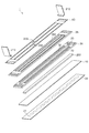
図3は、インクジェット式記録ヘッド1の概略構成を示す分解斜視図、図4は、インクジェット式記録ヘッド1の図2におけるA−A断面斜視図、図5は、インクジェット式記録ヘッド1の図2におけるA−AおよびB−B断面斜視図である。
In the middle of the longitudinal direction of the surface where the two
3 is an exploded perspective view showing a schematic configuration of the ink
図2〜図5において、インクジェット式記録ヘッド1は、流路形成基板10とノズルプレート20と保護基板30とリザーバー形成基板35とコンプライアンス基板40と駆動回路200とフレキシブル基板210とを備えている。
流路形成基板10とノズルプレート20と保護基板30とは、流路形成基板10をノズルプレート20と保護基板30とで挟むように積み重ねられ、保護基板30上には、リザーバー形成基板35が積み重ねられ、さらにリザーバー形成基板35上にコンプライアンス基板40が積み重ねられている。
駆動回路200は、流路形成基板10とリザーバー形成基板35との間で、保護基板30に形成された貫通孔33の中に配置されている。
2 to 5, the ink
The flow
The
図6は、インクジェット式記録ヘッド1のより詳しい構成を示す分解部分斜視図であり、リザーバー形成基板35およびコンプライアンス基板40が省略されている。図7(a)はインクジェット式記録ヘッド1の部分平面図であり、リザーバー形成基板35およびコンプライアンス基板40が省略されている。図7(b)は図7(a)におけるインクジェット式記録ヘッド1のC−C断面図、図7(c)は図7(a)におけるインクジェット式記録ヘッド1のD−D部分断面図である。
流路形成基板10は、例えば、面方位(110)のシリコン単結晶板からなる。流路形成基板10には、異方性エッチングによって、複数の圧力発生室12が2つの列13をなすように形成されている。ここで、列13は、インクジェット式記録ヘッド1の幅方向(長手方向に直交する方向)に並設されている。圧力発生室12のインクジェット式記録ヘッド1の幅方向の断面形状は台形状で、圧力発生室12は、インクジェット式記録ヘッド1の幅方向に長く形成されている。
FIG. 6 is an exploded partial perspective view showing a more detailed configuration of the ink
The flow
また、流路形成基板10の圧力発生室12の長手方向外側の領域には液体供給路としての連通部14が形成され、さらに、連通部14と各圧力発生室12とが、各圧力発生室12に設けられた液体供給路としてのインク供給路15を介して連通されている。インク供給路15は、圧力発生室12よりも狭い幅で形成されており、連通部14から圧力発生室12に流入するインクの流路抵抗を一定に保持している。
In addition, a
ノズルプレート20には、各圧力発生室12のインク供給路15とは反対側の端部近傍に、外部と連通するノズル開口21が穿設されている。
なお、ノズルプレート20は、ガラスセラミックス、シリコン単結晶基板または不錆鋼などからなる。
流路形成基板10とノズルプレート20とは、接着剤や熱溶着フィルム等によって固着されている。
In the
The
The flow
流路形成基板10のノズルプレート20が固着された面と対向する面には、振動板を構成する弾性膜50が形成されている。例えば、弾性膜50は、流路形成基板10を約1100℃の拡散炉で熱酸化して得られる二酸化シリコンからなる。
流路形成基板10の弾性膜50上には、酸化膜からなる絶縁体膜55が形成されている。例えば、絶縁体膜55は、酸化ジルコニウムからなり、スパッタリング法等によりジルコニウム膜を形成したのち、ジルコニウム膜を500℃〜1200℃の拡散炉で熱酸化することにより得られる。ここで、弾性膜50と絶縁体膜55とで振動板が構成される。
An
An
さらに、この絶縁体膜55上には、白金(Pt)などの金属やルテニウム酸ストロンチウム(SrRuO)などの金属酸化物からなる下電極60と、ペロブスカイト構造の圧電体層70と、金(Au)、イリジウム(Ir)などの金属からなる上電極80とが形成され、圧電素子300を構成している。ここで、圧電素子300は、下電極60、圧電体層70および上電極80を含む部分をいう。
Further, on the
例えば、下電極60は、白金(Pt)、イリジウム(Ir)、ルテニウム酸ストロンチウム(SrRuO)などの金属酸化物等からなる下電極膜を絶縁体膜55の全面に形成後、所定形状にパターニングして得られる。
例えば、圧電体層70および上電極80は以下の方法で形成することができる。
先ず、下電極60および絶縁体膜55上に、圧電材料からなる圧電体層膜を形成する。圧電材料としては、チタン酸ジルコン酸鉛(PZT)からなる圧電体層膜を用いることができる。
圧電体層膜の製造方法としては、金属有機物を触媒に溶解・分散したいわゆるゾルを塗布乾燥してゲル化し、さらに高温で焼成することで金属酸化物からなる圧電体層膜を得る、いわゆるゾル−ゲル法を用いることができる。
なお、ゾル−ゲル法に限定されず、例えば、MOD(Metal−Organic Decomposition)法等を用いてもよい。さらに、これらの液相法による圧電体層膜の製造方法に限定されず、スパッタリングなどの気相成長を用いた圧電体層膜の製造方法であってもよい。
For example, the
For example, the
First, a piezoelectric layer film made of a piezoelectric material is formed on the
As a method for producing a piezoelectric layer film, a so-called sol in which a so-called sol in which a metal organic material is dissolved and dispersed in a catalyst is applied, dried, gelled, and further baked at a high temperature to obtain a piezoelectric layer film made of a metal oxide. -A gel method can be used.
The method is not limited to the sol-gel method, and for example, a MOD (Metal-Organic Decomposition) method or the like may be used. Furthermore, it is not limited to the manufacturing method of the piezoelectric layer film by these liquid phase methods, The manufacturing method of the piezoelectric layer film using vapor phase growth, such as sputtering, may be used.
ゾル−ゲル法を詳しく説明すると、まず金属有機化合物を含むゾル(溶液)を塗布する。次いで、塗布により得られる圧電体前駆体膜を、所定温度に加熱して一定時間乾燥させ、ゾルの溶媒を蒸発させることで圧電体前駆体膜を乾燥させる。さらに、大気雰囲気下において一定の温度で一定時間、圧電体前駆体膜を脱脂する。
なお、ここで言う脱脂とは、ゾル膜の有機成分を、例えば、NO2、CO2、H2O等として離脱させることである。
The sol-gel method will be described in detail. First, a sol (solution) containing a metal organic compound is applied. Next, the piezoelectric precursor film obtained by coating is heated to a predetermined temperature and dried for a predetermined time, and the sol solvent is evaporated to dry the piezoelectric precursor film. Further, the piezoelectric precursor film is degreased at a constant temperature for a predetermined time in an air atmosphere.
Here, degreasing refers, the organic components of the sol film, for example, is to be detached as NO 2, CO 2, H 2 O or the like.
このような塗布・乾燥・脱脂の工程を、所定回数、例えば、2回繰り返すことで、圧電体前駆体膜を所定厚に形成し、この圧電体前駆体膜を拡散炉等で加熱処理することによって結晶化させて圧電体膜を形成する。すなわち、圧電体前駆体膜を焼成することで結晶が成長して圧電体膜が形成される。
焼成温度は、650℃〜850℃程度であることが好ましく、例えば、約700℃で30分間、圧電体前駆体膜を焼成して圧電体膜を形成する。このような条件で形成した圧電体膜の結晶は(100)面に優先配向する。
上述した塗布・乾燥・脱脂・焼成の工程を、複数回繰り返すことにより、多層の圧電体膜からなる所定厚さの圧電体層膜を形成する。
By repeating such coating, drying, and degreasing processes a predetermined number of times, for example, twice, a piezoelectric precursor film is formed to a predetermined thickness, and this piezoelectric precursor film is heated in a diffusion furnace or the like. To form a piezoelectric film. That is, by firing the piezoelectric precursor film, crystals grow and a piezoelectric film is formed.
The firing temperature is preferably about 650 ° C. to 850 ° C., for example, the piezoelectric precursor film is fired at about 700 ° C. for 30 minutes to form the piezoelectric film. Crystals of the piezoelectric film formed under such conditions are preferentially oriented in the (100) plane.
By repeating the above-described coating, drying, degreasing, and firing steps a plurality of times, a piezoelectric layer film having a predetermined thickness composed of a multilayer piezoelectric film is formed.
圧電体層膜の材料としては、例えば、チタン酸ジルコン酸鉛等の強誘電性圧電性材料に、ニオブ、ニッケル、マグネシウム、ビスマスまたはイットリウム等の金属を添加したリラクサ強誘電体等を用いてもよい。また、鉛を圧電材料に含まない、いわゆる非鉛の圧電材料からなる圧電素子を用いてもよい。 As a material of the piezoelectric layer film, for example, a relaxor ferroelectric material obtained by adding a metal such as niobium, nickel, magnesium, bismuth or yttrium to a ferroelectric piezoelectric material such as lead zirconate titanate may be used. Good. Moreover, you may use the piezoelectric element which consists of what is called a lead-free piezoelectric material which does not contain lead in a piezoelectric material.
圧電体層膜形成した後は、例えば、金(Au)、イリジウム(Ir)などからなる上電極膜を圧電体層膜の全面に形成する。上電極膜は、スパッタリング法、例えば、DCまたはRFスパッタリング法によって形成することができる。 After the piezoelectric layer film is formed, for example, an upper electrode film made of gold (Au), iridium (Ir), or the like is formed on the entire surface of the piezoelectric layer film. The upper electrode film can be formed by sputtering, for example, DC or RF sputtering.
圧電体層膜および上電極膜を、各圧力発生室12に対向する領域にパターニングして、下電極60、圧電体層70および上電極80を備えた圧電素子300を形成する。
The piezoelectric layer film and the upper electrode film are patterned in a region facing each
一般的には、圧電素子300のいずれか一方の電極を共通電極とし、他方の電極および圧電体層70を各圧力発生室12にパターニングして構成する。そして、ここではパターニングされたいずれか一方の電極および圧電体層70から構成され、両電極への電圧の印加により圧電歪みが生じる部分を圧電体能動部という。
なお、実施形態では、下電極60を圧電素子300の共通電極とし、上電極80を圧電素子300の個別電極としているが、駆動回路200や配線の都合でこれを逆にしても支障はない。いずれの場合においても、圧力発生室12毎に圧電体能動部が形成されていることになる。また、ここでは、圧電素子300と当該圧電素子300の駆動により変位が生じる弾性膜50および絶縁体膜55(振動板)とを合わせて圧電アクチュエーターと称する。
In general, one of the electrodes of the
In the embodiment, the
また、このような各圧電素子300を構成する上電極80には、例えば、金(Au)等からなる引き出し電極としてのリード電極90が接続されており、このリード電極90は、圧力発生室12の列13の間の領域まで引き出されている。
In addition, a
リード電極90は、流路形成基板10の全面に亘って、例えば、金(Au)等からなる金属層を形成し、その後、例えば、レジスト等からなる図示しないマスクパターンを介して金属層を圧電素子300毎にパターニングすることによってリード電極90を形成することによって得られる。
The
保護基板30は、圧電素子300に対向する領域に、圧電素子300の運動を阻害しない程度の空間を確保した状態の圧電素子保持部31を有する。圧電素子保持部31は、各圧力発生室12の2つの列13に対応して2つ設けられている。
圧電素子300が形成された流路形成基板10上には、保護基板30が接着剤56によって接着されている。
接着は、保護基板30とは別に用意した圧電素子300が形成された流路形成基板10と保護基板30とを、圧電素子300が圧電素子保持部31に収まるように向かい合わせ、接着剤56によって接着する。
接着は、接着面をプライマーで処理後、接着剤56を保護基板30の接着面に転写後、流路形成基板10と保護基板30とを貼り合せ、仮接着し硬化することで行なう。
The
On the flow
Adhesion is performed by bringing the flow
Adhesion is performed by treating the adhesive surface with a primer, transferring the adhesive 56 to the adhesive surface of the
なお、実施形態では、各圧電素子保持部31は、各圧力発生室12の列13に対応する領域に一体的に設けられているが、圧電素子300毎に独立して設けられていてもよい。
保護基板30の材料としては、例えば、ガラス、セラミックス材料、金属、樹脂等が挙げられるが、流路形成基板10の熱膨張率と略同一の材料で形成されていることがより好ましく、実施形態では、流路形成基板10と同一材料のシリコン単結晶基板を用いて形成する。
In the embodiment, each piezoelectric
Examples of the material of the
また、保護基板30には、流路形成基板10の連通部14に対応する領域から圧電素子保持部31上にわたってリザーバー部32が設けられている。このリザーバー部32は、実施形態では、圧力発生室12の列13に沿って設けられており、流路形成基板10の連通部14と連通されて各圧力発生室12の共通のインク室となるマニホールド100を構成している。
In addition, a
さらに、保護基板30の長手方向(図中の白抜き矢印方向)に直交する方向の略中央部、すなわち、圧力発生室12の列13間の対向する領域には、保護基板30を厚さ方向に貫通する貫通孔33が設けられている。
貫通孔33は、例えば、ドライエッチングによって形成できる。ドライエッチングとしては、例えば、RIE(Reactive Ion Etching)を用いることができる。例えば、深堀RIEを用いることができる。深堀RIEとは、アスペクト比の高い(狭く深い)反応性イオンエッチングをいう。深く掘る手法は通常高密度プラズマを使い、サンプルを低温に冷やす方法とボッシュプロセスと呼ばれるエッチング技術を用いる方法、またはその両方を用いる。
Further, the
The through
ボッシュプロセスは、エッチングとエッチング側壁保護を繰り返しながら行うエッチング手法でアスペクト比の高いエッチングが可能である。
プロセスは以下の2つの処理を繰り返す。場合によってはさらにステップが増えることもある。
エッチングステップ:主に六フッ化硫黄(SF6)を用いて等方エッチングを行う。エッチング穴底面に保護膜が付いている場合があるので底面の保護膜を除去する働きもある。
保護ステップ:テフロン(登録商標)系のガス(C4F8など)を用いて側壁を保護する。側壁を保護することで横方向のエッチングを抑制する。
保護膜により横方向のエッチングが抑制されるため細く深い(高アスペクト比)穴を掘ることができる。側壁の角度はほぼ垂直にすることができ、また、プロセス条件を変えることで他の角度にもできる。
高密度プラズマを発生する方法は主に、ICP(誘導結合プラズマ)RIE、ECR(Electron Cyclotron Resonance)RIEと呼ばれるマイクロ波を用いた方法等が用いられる。
The Bosch process is an etching method in which etching and etching sidewall protection are repeated, and etching with a high aspect ratio is possible.
The process repeats the following two processes. In some cases, additional steps may be added.
Etching step: Isotropic etching is mainly performed using sulfur hexafluoride (SF6). Since there is a case where a protective film is attached to the bottom of the etching hole, it also serves to remove the protective film on the bottom.
Protection step: Teflon (registered trademark) -based gas (such as C4F8) is used to protect the sidewall. The lateral etching is suppressed by protecting the side wall.
Since the etching in the lateral direction is suppressed by the protective film, a narrow and deep (high aspect ratio) hole can be dug. The sidewall angle can be nearly vertical, and can be changed to other angles by changing the process conditions.
As a method for generating high-density plasma, a method using a microwave called ICP (Inductively Coupled Plasma) RIE, ECR (Electron Cyclotron Resonance) RIE, or the like is mainly used.
圧電素子300から引き出されたリード電極90は、少なくともその先端部が貫通孔33の底部に露出している。
駆動回路200は貫通孔33内に収められている。貫通孔33に露出したリード電極90の先端部に駆動回路200は載せられ、リード電極90の先端部と駆動回路200の図示しない端子とが接続されている。
The
The
駆動信号は、例えば、駆動電源信号等の駆動ICを駆動させるための駆動系信号のほか、シリアル信号(SI)等の各種制御系信号を含み、配線は、それぞれの信号が供給される複数の配線で構成される。 The drive signal includes, for example, a drive system signal for driving the drive IC such as a drive power supply signal, and various control system signals such as a serial signal (SI), and the wiring includes a plurality of signals supplied with the respective signals. Consists of wiring.
保護基板30上には、リザーバー形成基板35が積み重ねられ、貫通孔33上にリザーバー部32の一部を形成している。また、リザーバー形成基板35には、長手方向(図中の白抜き矢印方向)に直交する方向の略中央部に貫通孔33に蓋をするように長手方向にわたって桁36が形成されている。ここで、桁36と駆動回路200との間には、熱伝導部材400が挟まれ、桁36と駆動回路200とに接触している。
熱伝導部材400としては、接着剤等の樹脂、シリコングリース、セラミックフィラーをシリコンに高充填したグリース、放熱シートを用いることができる。
A
As the heat
リザーバー形成基板35の上には、圧力吸収部材としての封止膜41および固定板42とからなるコンプライアンス基板40が接合されている。ここで、封止膜41は、剛性が低く可撓性を有する材料(例えば、厚さが6μmのポリフェニレンサルファイド(PPS)フィルム)からなり、この封止膜41によってリザーバー部32の一方面が封止されている。また、固定板42は、金属等の硬質の材料(例えば、厚さが30μmのステンレス鋼(SUS)等)で形成されている。この固定板42のマニホールド100に対向する領域は、厚さ方向に完全に除去された開口部43となっているため、マニホールド100の一方面は可撓性を有する封止膜41のみで封止されている。
On the
インクジェット式記録ヘッド1では、カートリッジ2Aおよび2Bからインクを取り込み、マニホールド100からノズル開口21に至るまで内部をインクで満たした後、駆動回路200からの記録信号に従い、圧力発生室12に対応するそれぞれの下電極60と上電極80との間に電圧が印加される。電圧の印加によって、弾性膜50および圧電体層70がたわみ変形し、各圧力発生室12内の圧力が高まりノズル開口21からインク滴が吐出する。
In the ink
インクジェット式記録ヘッド1は、インク供給手段であるインクカートリッジ等と連通するインク流路を具備する記録ヘッドユニットの一部を構成して、インクジェット式記録装置1000に搭載される。
The ink
このような実施形態によれば、以下の効果がある。
(1)リザーバー部32が貫通孔33上にも形成されているので、コンプライアンス基板40の封止膜41の面積を大きく取ることができ、圧力変動の吸収効率がよくできる。
特に、カートリッジ2Aおよび2Bを、インクジェット式記録ヘッド1と繋げる際にリザーバー部32、圧力発生室12、連通部14およびインク供給路15内に発生する大きな圧力変動を吸収することができる。
また、流路形成基板10、保護基板30、リザーバー形成基板35の積み重ねられた方向の貫通孔33の上にもリザーバー部32の一部が形成されているので、貫通孔33を避けて、これらの基板を広げてリザーバー部32を形成した場合と比較して、コストを抑えた、小型のインクジェット式記録ヘッド1を得ることができる。
According to such an embodiment, there are the following effects.
(1) Since the
In particular, large pressure fluctuations generated in the
In addition, since a part of the
(2)圧電素子300から引き出されたリード電極90が駆動回路200に接続される方向とは異なる方向で、フレキシブル基板210が駆動回路200に接続されているので、圧電素子300から引き出されるリード電極90の方向に対し、より小型のインクジェット式記録ヘッド1を得ることができる。
(2) Since the
(3)駆動回路200で発生した熱がリザーバー形成基板35を介して逃げ、駆動回路200で発生した熱による圧電素子300の特性の変化、圧力発生室12、連通部14およびインク供給路15の容量の変動、流路形成基板10、保護基板30、リザーバー形成基板35およびコンプライアンス基板40の熱膨張差による各基板間の剥離を抑えることができる。したがって、インクの吐出状態の変動が少なく、基板間からのインクの漏れが抑えられた耐久性の向上したインクジェット式記録ヘッド1を得ることができる。
(3) The heat generated in the
(4)前述の効果を達成できるインクジェット式記録装置1000を得ることができる。
(4) The ink
上述した実施形態では、液体噴射ヘッドの一例としてインクジェット式記録ヘッドを挙げて説明したが、本発明は広く液体噴射ヘッド全般を対象としたものであり、インク以外の液体を噴射する液体噴射ヘッドにも勿論適用することができる。
その他の液体噴射ヘッドとしては、例えば、プリンター等の画像記録装置に用いられる各種の記録ヘッド、液晶ディスプレイ等のカラーフィルターの製造に用いられる色材噴射ヘッド、有機ELディスプレイ、FED(電界放出ディスプレイ)等の電極形成に用いられる電極材料噴射ヘッド、バイオchip製造に用いられる生体有機物噴射ヘッド等が挙げられる。
In the above-described embodiment, an ink jet recording head has been described as an example of a liquid ejecting head. However, the present invention is widely intended for all liquid ejecting heads, and is a liquid ejecting head that ejects liquid other than ink. Of course, it can also be applied.
Other liquid ejecting heads include, for example, various recording heads used in image recording apparatuses such as printers, color material ejecting heads used in the manufacture of color filters such as liquid crystal displays, organic EL displays, and FEDs (field emission displays). Examples thereof include an electrode material ejection head used for electrode formation, a bioorganic matter ejection head used for biochip production, and the like.
1…液体噴射ヘッドとしてのインクジェット式記録ヘッド、1A,1B…記録ヘッドユニット、2A,2B…カートリッジ、3…キャリッジ、4…装置本体、5…キャリッジ軸、6…駆動モーター、7…タイミングベルト、8…プラテン、10…流路形成基板、12…圧力発生室、13…列、14…液体供給路としての連通部、15…液体供給路としてのインク供給路、20…ノズルプレート、21…ノズル開口、30…保護基板、31…圧電素子保持部、32…リザーバー部、33…貫通孔、35…リザーバー形成基板、36…桁、40…コンプライアンス基板、41…圧力吸収部材としての封止膜、42…固定板、43…開口部、50…弾性膜、55…絶縁体膜、56…接着剤、60…下電極、70…圧電体層、80…上電極、90…リード電極、100…マニホールド、200…駆動回路、210…配線基板としてのフレキシブル基板、220…開口、230…インク導入口、300…圧電素子、400…熱伝導部材、1000…インクジェット式記録装置。
DESCRIPTION OF
Claims (20)
前記ノズル開口に連通した圧力発生室に前記液体を供給する液体供給路を有する流路形成基板と、
前記流路形成基板上に形成され、前記圧力発生室の圧力を変化させる圧電素子と、
前記圧電素子と接続された駆動回路と、
前記圧電素子を保護する圧電素子保持部、および、前記駆動回路が配置された貫通孔を有する保護基板と、
前記駆動回路と接続された配線基板と、
前記配線基板が配置された開口を有し、前記貫通孔を覆うリザーバー形成基板と、
前記保護基板および前記リザーバー形成基板に一部が形成されたリザーバー部と、を備えた
ことを特徴とする液体噴射ヘッド。 A liquid ejecting head in which a plurality of nozzle openings for ejecting liquid are arranged side by side,
A flow path forming substrate having a liquid supply path for supplying the liquid to a pressure generating chamber communicating with the nozzle opening;
A piezoelectric element formed on the flow path forming substrate and changing the pressure of the pressure generating chamber;
A drive circuit connected to the piezoelectric element;
A piezoelectric element holding portion for protecting the piezoelectric element, and a protective substrate having a through-hole in which the drive circuit is disposed;
A wiring board connected to the drive circuit;
A reservoir forming substrate having an opening in which the wiring substrate is disposed and covering the through hole;
A liquid ejecting head comprising: the protective substrate; and a reservoir portion partially formed on the reservoir forming substrate.
前記ノズル開口に連通した圧力発生室に前記液体を供給する液体供給路を有する流路形成基板と、
前記流路形成基板上に形成され、前記圧力発生室の圧力を変化させる圧電素子と、
前記圧電素子と接続された駆動回路と、
前記圧電素子を保護する圧電素子保持部、および、前記駆動回路が配置された貫通孔を有する保護基板と、
前記駆動回路と接続された配線基板であって、前記駆動回路を挟む位置に配置された複数の配線基板と、
前記貫通孔を覆うリザーバー形成基板と、
前記保護基板および前記リザーバー形成基板に一部が形成されたリザーバー部と、を備
えた
ことを特徴とする液体噴射ヘッド。 A liquid ejecting head in which a plurality of nozzle openings for ejecting liquid are arranged side by side,
A flow path forming substrate having a liquid supply path for supplying the liquid to a pressure generating chamber communicating with the nozzle opening;
A piezoelectric element formed on the flow path forming substrate and changing the pressure of the pressure generating chamber;
A drive circuit connected to the piezoelectric element;
A piezoelectric element holding portion for protecting the piezoelectric element, and a protective substrate having a through-hole in which the drive circuit is disposed;
A plurality of wiring boards connected to the driving circuit, the wiring boards arranged at positions sandwiching the driving circuit;
A reservoir forming substrate covering the through hole;
A liquid ejecting head comprising: the protective substrate; and a reservoir portion partially formed on the reservoir forming substrate.
前記リザーバー形成基板は、前記配線基板が配置された開口を有する、
ことを特徴とする液体噴射ヘッド。 The liquid ejecting head according to claim 2 , further comprising:
The reservoir forming substrate has an opening in which the wiring substrate is disposed.
A liquid jet head characterized by that.
複数の前記配線基板であって、前記駆動回路を挟む位置に配置された複数の前記配線基板を備える、
ことを特徴とする液体噴射ヘッド。 The liquid ejecting head according to claim 1 , further comprising:
A plurality of the wiring boards, comprising a plurality of the wiring boards arranged at positions sandwiching the drive circuit;
A liquid jet head characterized by that.
前記配線基板は、前記流路形成基板上に形成された電極を介して前記駆動回路と接続された、
ことを特徴とする液体噴射ヘッド。 The liquid ejecting head according to any one of claims 1 to 4 , further comprising:
The wiring board is connected to the drive circuit via an electrode formed on the flow path forming substrate,
A liquid jet head characterized by that.
前記リザーバー部は、導入口から前記液体を供給される、
ことを特徴とする液体噴射ヘッド。 In the liquid jet head according to any one of claims 1 to 5 ,
The reservoir unit is supplied with the liquid from the inlet,
A liquid jet head characterized by that.
前記圧電素子保持部は、前記圧電素子毎に前記圧電素子を保護する、
ことを特徴とする液体噴射ヘッド。 The liquid ejecting head according to any one of claims 1 to 6, further
The piezoelectric element holding unit protects the piezoelectric element for each piezoelectric element.
A liquid jet head characterized by that.
前記リザーバー部を封止し、前記リザーバー部の圧力変動を吸収する圧力吸収部材を備えたことを特徴とする液体噴射ヘッド。 The liquid ejecting head according to any one of claims 1 to 7, further
A liquid ejecting head comprising a pressure absorbing member that seals the reservoir and absorbs pressure fluctuations in the reservoir.
前記ノズル開口に連通した圧力発生室に前記液体を供給する液体供給路を有する流路形成基板と、
前記流路形成基板上に形成され、前記圧力発生室の圧力を変化させる圧電素子と、
前記圧電素子を保護する圧電素子保持部および前記圧電素子から引き出されたリード電極を露出させる貫通孔を有する保護基板と、
前記貫通孔に収められ、前記リード電極と接続された駆動回路と、
前記貫通孔上のリザーバー形成基板に一部が形成されたリザーバー部と、
前記リザーバー部を封止し、圧力吸収部材によって前記リザーバー部の圧力変動を吸収するコンプライアンス基板と、
前記駆動回路に接続された配線基板とを備え、
前記配線基板は、前記リザーバー形成基板に設けられた開口に挿入された
ことを特徴とする液体噴射ヘッド。 A liquid ejecting head in which a plurality of nozzle openings for ejecting liquid are arranged side by side,
A flow path forming substrate having a liquid supply path for supplying the liquid to a pressure generating chamber communicating with the nozzle opening;
A piezoelectric element formed on the flow path forming substrate and changing the pressure of the pressure generating chamber;
A protective substrate having a piezoelectric element holding portion that protects the piezoelectric element and a through-hole that exposes a lead electrode drawn from the piezoelectric element;
A drive circuit housed in the through hole and connected to the lead electrode;
A reservoir part partially formed on a reservoir forming substrate on the through hole;
A compliance substrate that seals the reservoir and absorbs pressure fluctuations of the reservoir by a pressure absorbing member;
A wiring board connected to the drive circuit,
The liquid ejecting head, wherein the wiring substrate is inserted into an opening provided in the reservoir forming substrate.
前記ノズル開口に連通した圧力発生室に前記液体を供給する液体供給路を有する流路形成基板と、
前記流路形成基板上に形成され、前記圧力発生室の圧力を変化させる圧電素子と、
前記圧電素子を保護する圧電素子保持部および前記圧電素子から引き出されたリード電極を露出させる貫通孔を有する保護基板と、
前記貫通孔に収められ、前記リード電極と接続された駆動回路と、
前記貫通孔上のリザーバー形成基板に一部が形成されたリザーバー部と、
前記リザーバー部を封止し、圧力吸収部材によって前記リザーバー部の圧力変動を吸収するコンプライアンス基板と、
前記駆動回路に接続された複数の配線基板とを備え、
複数の前記配線基板は、前記駆動回路を挟む位置に配置された
ことを特徴とする液体噴射ヘッド。 A liquid ejecting head in which a plurality of nozzle openings for ejecting liquid are arranged side by side,
A flow path forming substrate having a liquid supply path for supplying the liquid to a pressure generating chamber communicating with the nozzle opening;
A piezoelectric element formed on the flow path forming substrate and changing the pressure of the pressure generating chamber;
A protective substrate having a piezoelectric element holding portion that protects the piezoelectric element and a through-hole that exposes a lead electrode drawn from the piezoelectric element;
A drive circuit housed in the through hole and connected to the lead electrode;
A reservoir part partially formed on a reservoir forming substrate on the through hole;
A compliance substrate that seals the reservoir and absorbs pressure fluctuations of the reservoir by a pressure absorbing member;
A plurality of wiring boards connected to the drive circuit,
The liquid jet head, wherein the plurality of wiring boards are arranged at positions sandwiching the drive circuit.
前記ノズル開口に連通した圧力発生室に前記液体を供給する液体供給路を有する流路形成基板と、
前記流路形成基板上に形成され、前記圧力発生室の圧力を変化させる圧電素子と、
前記圧電素子を保護する圧電素子保持部および前記圧電素子から引き出されたリード電極を露出させる貫通孔を有する保護基板と、
前記貫通孔に収められ、前記リード電極と接続された駆動回路と、
前記貫通孔上のリザーバー形成基板に一部が形成されたリザーバー部と、
前記リザーバー部を封止し、圧力吸収部材によって前記リザーバー部の圧力変動を吸収するコンプライアンス基板と、
前記駆動回路に接続された配線基板とを備え、
前記駆動回路および前記配線基板は、前記流路形成基板上に形成された電極を介して接続された
ことを特徴とする液体噴射ヘッド。 A liquid ejecting head in which a plurality of nozzle openings for ejecting liquid are arranged side by side,
A flow path forming substrate having a liquid supply path for supplying the liquid to a pressure generating chamber communicating with the nozzle opening;
A piezoelectric element formed on the flow path forming substrate and changing the pressure of the pressure generating chamber;
A protective substrate having a piezoelectric element holding portion that protects the piezoelectric element and a through-hole that exposes a lead electrode drawn from the piezoelectric element;
A drive circuit housed in the through hole and connected to the lead electrode;
A reservoir part partially formed on a reservoir forming substrate on the through hole;
A compliance substrate that seals the reservoir and absorbs pressure fluctuations of the reservoir by a pressure absorbing member;
A wiring board connected to the drive circuit,
The liquid ejecting head, wherein the driving circuit and the wiring board are connected via an electrode formed on the flow path forming substrate.
前記ノズル開口に連通した圧力発生室に前記液体を供給する液体供給路を有する流路形成基板と、
前記流路形成基板上に形成され、前記圧力発生室の圧力を変化させる圧電素子と、
前記圧電素子を保護する圧電素子保持部および前記圧電素子から引き出されたリード電極を露出させる貫通孔を有する保護基板と、
前記貫通孔に収められ、前記リード電極と接続された駆動回路と、
前記貫通孔上のリザーバー形成基板に一部が形成されたリザーバー部と、
前記リザーバー部を封止し、圧力吸収部材によって前記リザーバー部の圧力変動を吸収するコンプライアンス基板とを備え、
前記保護基板は、前記リザーバー部の一部を形成する孔を有する
ことを特徴とする液体噴射ヘッド。 A liquid ejecting head in which a plurality of nozzle openings for ejecting liquid are arranged side by side,
A flow path forming substrate having a liquid supply path for supplying the liquid to a pressure generating chamber communicating with the nozzle opening;
A piezoelectric element formed on the flow path forming substrate and changing the pressure of the pressure generating chamber;
A protective substrate having a piezoelectric element holding portion that protects the piezoelectric element and a through-hole that exposes a lead electrode drawn from the piezoelectric element;
A drive circuit housed in the through hole and connected to the lead electrode;
A reservoir part partially formed on a reservoir forming substrate on the through hole;
A compliance substrate that seals the reservoir and absorbs pressure fluctuations of the reservoir by a pressure absorbing member;
The liquid ejecting head, wherein the protective substrate has a hole forming a part of the reservoir portion.
前記ノズル開口に連通した圧力発生室に前記液体を供給する液体供給路を有する流路形成基板と、
前記流路形成基板上に形成され、前記圧力発生室の圧力を変化させる圧電素子と、
前記圧電素子を保護する圧電素子保持部および前記圧電素子から引き出されたリード電極を露出させる貫通孔を有する保護基板と、
前記貫通孔に収められ、前記リード電極と接続された駆動回路と、
前記貫通孔上のリザーバー形成基板に一部が形成されたリザーバー部と、
前記リザーバー部を封止し、圧力吸収部材によって前記リザーバー部の圧力変動を吸収するコンプライアンス基板とを備え、
前記保護基板は、複数の前記圧電素子を収める圧電素子保持部を、複数の前記圧電素子に対応する領域に一体的に有する
ことを特徴とする液体噴射ヘッド。 A liquid ejecting head in which a plurality of nozzle openings for ejecting liquid are arranged side by side,
A flow path forming substrate having a liquid supply path for supplying the liquid to a pressure generating chamber communicating with the nozzle opening;
A piezoelectric element formed on the flow path forming substrate and changing the pressure of the pressure generating chamber;
A protective substrate having a piezoelectric element holding portion that protects the piezoelectric element and a through-hole that exposes a lead electrode drawn from the piezoelectric element;
A drive circuit housed in the through hole and connected to the lead electrode;
A reservoir part partially formed on a reservoir forming substrate on the through hole;
A compliance substrate that seals the reservoir and absorbs pressure fluctuations of the reservoir by a pressure absorbing member;
The liquid ejecting head according to claim 1, wherein the protective substrate integrally includes a piezoelectric element holding portion that accommodates the plurality of piezoelectric elements in a region corresponding to the plurality of piezoelectric elements.
前記駆動回路に接続された配線基板を備え、
前記配線基板は、前記リザーバー形成基板に設けられた開口に挿入された
ことを特徴とする液体噴射ヘッド。 The liquid ejecting head according to any one of claims 10 to 13 , further comprising:
Comprising a wiring board connected to the drive circuit;
The liquid ejecting head, wherein the wiring substrate is inserted into an opening provided in the reservoir forming substrate.
前記駆動回路に接続された複数の配線基板を備え、
複数の前記配線基板は、前記駆動回路を挟む位置に配置された
ことを特徴とする液体噴射ヘッド。 The liquid ejecting head according to any one of claims 9 to 14 , wherein the liquid ejecting head according to any one of claims 9 to 14 (excluding claim 10 and a claim quoting claim 10) is further provided.
Comprising a plurality of wiring boards connected to the drive circuit;
The liquid jet head, wherein the plurality of wiring boards are arranged at positions sandwiching the drive circuit.
前記駆動回路に接続された配線基板を備え、
前記駆動回路および前記配線基板は、前記流路形成基板上に形成された電極を介して接続された
ことを特徴とする液体噴射ヘッド。 The liquid ejecting head according to any one of claims 9 to 15 , wherein the liquid ejecting head according to any one of claims 9 to 15 (excluding claim 11 and a claim quoting claim 11) is further provided.
Comprising a wiring board connected to the drive circuit;
The liquid ejecting head, wherein the driving circuit and the wiring board are connected via an electrode formed on the flow path forming substrate.
前記リザーバー部は、導入口から液体を供給される
ことを特徴とする液体噴射ヘッド。 The liquid ejecting head according to any one of Claims 9 to 16 ,
The liquid ejecting head , wherein the reservoir is supplied with liquid from an introduction port.
前記保護基板は、前記リザーバー部の一部を形成する孔を有する
ことを特徴とする液体噴射ヘッド。 In the liquid ejecting head according to any one of claims 9 to 17 , except for claim 12 and a claim that cites claim 12 .
The liquid ejecting head, wherein the protective substrate has a hole forming a part of the reservoir portion.
前記保護基板は、複数の前記圧電素子を収める圧電素子保持部を、前記圧電素子毎に有する
ことを特徴とする液体噴射ヘッド。 The liquid ejecting head according to any one of claims 9 to 18 (except for claim 13 and a claim that cites claim 13) .
The liquid ejecting head according to claim 1, wherein the protective substrate includes a piezoelectric element holding portion that accommodates the plurality of piezoelectric elements for each of the piezoelectric elements.
ことを特徴とする液体噴射装置。 A liquid ejecting apparatus comprising the liquid ejecting head according to any one of claims 1 to 19 .
Priority Applications (1)
| Application Number | Priority Date | Filing Date | Title |
|---|---|---|---|
| JP2016118611A JP6249050B2 (en) | 2016-06-15 | 2016-06-15 | Liquid ejecting head and liquid ejecting apparatus |
Applications Claiming Priority (1)
| Application Number | Priority Date | Filing Date | Title |
|---|---|---|---|
| JP2016118611A JP6249050B2 (en) | 2016-06-15 | 2016-06-15 | Liquid ejecting head and liquid ejecting apparatus |
Related Parent Applications (1)
| Application Number | Title | Priority Date | Filing Date |
|---|---|---|---|
| JP2011266549A Division JP5953723B2 (en) | 2011-12-06 | 2011-12-06 | Liquid ejecting head and liquid ejecting apparatus |
Related Child Applications (1)
| Application Number | Title | Priority Date | Filing Date |
|---|---|---|---|
| JP2017222480A Division JP6409944B2 (en) | 2017-11-20 | 2017-11-20 | Liquid ejecting head and liquid ejecting apparatus |
Publications (3)
| Publication Number | Publication Date |
|---|---|
| JP2016164004A JP2016164004A (en) | 2016-09-08 |
| JP2016164004A5 JP2016164004A5 (en) | 2017-05-18 |
| JP6249050B2 true JP6249050B2 (en) | 2017-12-20 |
Family
ID=56876207
Family Applications (1)
| Application Number | Title | Priority Date | Filing Date |
|---|---|---|---|
| JP2016118611A Active JP6249050B2 (en) | 2016-06-15 | 2016-06-15 | Liquid ejecting head and liquid ejecting apparatus |
Country Status (1)
| Country | Link |
|---|---|
| JP (1) | JP6249050B2 (en) |
Families Citing this family (3)
| Publication number | Priority date | Publication date | Assignee | Title |
|---|---|---|---|---|
| JP7106828B2 (en) * | 2017-09-13 | 2022-07-27 | セイコーエプソン株式会社 | Liquid ejecting head, liquid ejecting apparatus, piezoelectric device, and liquid ejecting head manufacturing method |
| CN110722880B (en) * | 2018-07-17 | 2021-01-12 | 精工爱普生株式会社 | Head unit and liquid ejecting apparatus |
| WO2024048526A1 (en) * | 2022-08-29 | 2024-03-07 | 京セラ株式会社 | Liquid ejection head and recording device |
Family Cites Families (9)
| Publication number | Priority date | Publication date | Assignee | Title |
|---|---|---|---|---|
| JP2002046281A (en) * | 2000-08-01 | 2002-02-12 | Seiko Epson Corp | Ink jet recording head and its manufacturing method and ink jet recorder |
| JP2005209898A (en) * | 2004-01-23 | 2005-08-04 | Seiko Epson Corp | Piezoelectric material element, manufacturing method thereof, and liquid injection head |
| JP2006116767A (en) * | 2004-10-20 | 2006-05-11 | Seiko Epson Corp | Liquid droplet discharging head and liquid droplet discharging apparatus |
| JP2010069688A (en) * | 2008-09-17 | 2010-04-02 | Seiko Epson Corp | Liquid jetting head and liquid jetting apparatus |
| JP5403228B2 (en) * | 2009-03-26 | 2014-01-29 | セイコーエプソン株式会社 | Liquid ejecting head unit and liquid ejecting apparatus |
| US8454132B2 (en) * | 2009-12-14 | 2013-06-04 | Fujifilm Corporation | Moisture protection of fluid ejector |
| JP5716431B2 (en) * | 2011-02-04 | 2015-05-13 | 株式会社リコー | Inkjet recording head, ink cartridge, inkjet recording apparatus, and image forming apparatus. |
| JP5776214B2 (en) * | 2011-02-18 | 2015-09-09 | 株式会社リコー | Droplet discharge head and image forming apparatus |
| JP2013028033A (en) * | 2011-07-27 | 2013-02-07 | Ricoh Co Ltd | Droplet ejection head and image forming apparatus |
-
2016
- 2016-06-15 JP JP2016118611A patent/JP6249050B2/en active Active
Also Published As
| Publication number | Publication date |
|---|---|
| JP2016164004A (en) | 2016-09-08 |
Similar Documents
| Publication | Publication Date | Title |
|---|---|---|
| JP5953723B2 (en) | Liquid ejecting head and liquid ejecting apparatus | |
| JP6394903B2 (en) | Head and liquid ejecting apparatus | |
| JP2012000873A (en) | Method for producing liquid-ejecting head | |
| US20090289999A1 (en) | Liquid ejecting head and liquid ejecting apparatus including the same | |
| US10682854B2 (en) | Liquid ejecting head, liquid ejecting apparatus, piezoelectric device, and method of manufacturing liquid ejecting head | |
| JP6249050B2 (en) | Liquid ejecting head and liquid ejecting apparatus | |
| JP2008284781A (en) | Liquid ejection head, its manufacturing process, and liquid ejector | |
| JP2009016625A (en) | Actuator, liquid injection head, and liquid injection apparatus | |
| JP2009143002A (en) | Liquid jet head and liquid jet apparatus | |
| JP5472596B2 (en) | Liquid ejecting head and liquid ejecting apparatus using the same | |
| JP5297576B2 (en) | Piezoelectric element, actuator device, liquid jet head, and liquid jet device | |
| JP3931976B2 (en) | Actuator device, ink jet recording head, and ink jet recording device | |
| JP2003291343A (en) | Liquid ejection head, its manufacturing method and liquid ejector | |
| JP6149453B2 (en) | Liquid ejecting head, liquid ejecting apparatus, and method of manufacturing liquid ejecting head | |
| JP2012011558A (en) | Method of manufacturing liquid ejection head | |
| JP5581781B2 (en) | Method for manufacturing piezoelectric actuator | |
| US9566790B2 (en) | Method of forming stacked wiring | |
| JP7009857B2 (en) | Liquid injection head, liquid injection device, and piezoelectric device | |
| JP6409944B2 (en) | Liquid ejecting head and liquid ejecting apparatus | |
| JP6714881B2 (en) | Liquid ejecting head and liquid ejecting apparatus | |
| JP5760616B2 (en) | Method for manufacturing liquid jet head | |
| JP4888647B2 (en) | Liquid ejecting head and liquid ejecting apparatus | |
| JP2009226744A (en) | Liquid injection head, liquid injection apparatus, and manufacturing method of liquid injection head | |
| JP2010228272A (en) | Method for manufacturing liquid jetting head, liquid jetting head, and liquid jetting device | |
| JP2012025096A (en) | Piezoelectric element, liquid ejection head, and liquid ejection device |
Legal Events
| Date | Code | Title | Description |
|---|---|---|---|
| A521 | Written amendment |
Free format text: JAPANESE INTERMEDIATE CODE: A523 Effective date: 20160714 |
|
| A621 | Written request for application examination |
Free format text: JAPANESE INTERMEDIATE CODE: A621 Effective date: 20160714 |
|
| A521 | Written amendment |
Free format text: JAPANESE INTERMEDIATE CODE: A523 Effective date: 20170316 |
|
| A521 | Written amendment |
Free format text: JAPANESE INTERMEDIATE CODE: A523 Effective date: 20170329 |
|
| A977 | Report on retrieval |
Free format text: JAPANESE INTERMEDIATE CODE: A971007 Effective date: 20170426 |
|
| A131 | Notification of reasons for refusal |
Free format text: JAPANESE INTERMEDIATE CODE: A131 Effective date: 20170509 |
|
| A521 | Written amendment |
Free format text: JAPANESE INTERMEDIATE CODE: A523 Effective date: 20170615 |
|
| TRDD | Decision of grant or rejection written | ||
| A01 | Written decision to grant a patent or to grant a registration (utility model) |
Free format text: JAPANESE INTERMEDIATE CODE: A01 Effective date: 20171024 |
|
| A61 | First payment of annual fees (during grant procedure) |
Free format text: JAPANESE INTERMEDIATE CODE: A61 Effective date: 20171106 |
|
| R150 | Certificate of patent or registration of utility model |
Ref document number: 6249050 Country of ref document: JP Free format text: JAPANESE INTERMEDIATE CODE: R150 |