JP6247644B2 - Implant insertion device having a continuously adjustable targeting assembly - Google Patents
Implant insertion device having a continuously adjustable targeting assembly Download PDFInfo
- Publication number
- JP6247644B2 JP6247644B2 JP2014556760A JP2014556760A JP6247644B2 JP 6247644 B2 JP6247644 B2 JP 6247644B2 JP 2014556760 A JP2014556760 A JP 2014556760A JP 2014556760 A JP2014556760 A JP 2014556760A JP 6247644 B2 JP6247644 B2 JP 6247644B2
- Authority
- JP
- Japan
- Prior art keywords
- targeting
- opening
- insertion device
- guide sleeve
- implant insertion
- Prior art date
- Legal status (The legal status is an assumption and is not a legal conclusion. Google has not performed a legal analysis and makes no representation as to the accuracy of the status listed.)
- Active
Links
- 230000008685 targeting Effects 0.000 title claims description 94
- 239000007943 implant Substances 0.000 title claims description 58
- 238000003780 insertion Methods 0.000 title claims description 58
- 230000037431 insertion Effects 0.000 title claims description 58
- 230000007246 mechanism Effects 0.000 claims description 34
- 210000000988 bone and bone Anatomy 0.000 description 23
- 241000587161 Gomphocarpus Species 0.000 description 17
- 239000000463 material Substances 0.000 description 9
- 239000010935 stainless steel Substances 0.000 description 8
- 229910001220 stainless steel Inorganic materials 0.000 description 8
- 210000000689 upper leg Anatomy 0.000 description 6
- 238000000034 method Methods 0.000 description 5
- 230000002093 peripheral effect Effects 0.000 description 5
- 230000008859 change Effects 0.000 description 4
- 229920000049 Carbon (fiber) Polymers 0.000 description 3
- 239000004917 carbon fiber Substances 0.000 description 3
- 239000002131 composite material Substances 0.000 description 3
- 210000002758 humerus Anatomy 0.000 description 3
- VNWKTOKETHGBQD-UHFFFAOYSA-N methane Chemical compound C VNWKTOKETHGBQD-UHFFFAOYSA-N 0.000 description 3
- 239000004033 plastic Substances 0.000 description 3
- 210000002303 tibia Anatomy 0.000 description 3
- 208000010392 Bone Fractures Diseases 0.000 description 2
- 244000261422 Lysimachia clethroides Species 0.000 description 2
- 230000008878 coupling Effects 0.000 description 2
- 238000010168 coupling process Methods 0.000 description 2
- 238000005859 coupling reaction Methods 0.000 description 2
- 210000003414 extremity Anatomy 0.000 description 2
- 230000004927 fusion Effects 0.000 description 2
- 230000001788 irregular Effects 0.000 description 2
- 208000008924 Femoral Fractures Diseases 0.000 description 1
- RTAQQCXQSZGOHL-UHFFFAOYSA-N Titanium Chemical compound [Ti] RTAQQCXQSZGOHL-UHFFFAOYSA-N 0.000 description 1
- 230000009471 action Effects 0.000 description 1
- 229910045601 alloy Inorganic materials 0.000 description 1
- 239000000956 alloy Substances 0.000 description 1
- 230000000694 effects Effects 0.000 description 1
- 239000000835 fiber Substances 0.000 description 1
- 238000011065 in-situ storage Methods 0.000 description 1
- 229910052751 metal Inorganic materials 0.000 description 1
- 239000002184 metal Substances 0.000 description 1
- 230000008439 repair process Effects 0.000 description 1
- 239000010936 titanium Substances 0.000 description 1
- 229910052719 titanium Inorganic materials 0.000 description 1
- 238000003466 welding Methods 0.000 description 1
Images


Classifications
-
- A—HUMAN NECESSITIES
- A61—MEDICAL OR VETERINARY SCIENCE; HYGIENE
- A61B—DIAGNOSIS; SURGERY; IDENTIFICATION
- A61B17/00—Surgical instruments, devices or methods, e.g. tourniquets
- A61B17/16—Bone cutting, breaking or removal means other than saws, e.g. Osteoclasts; Drills or chisels for bones; Trepans
- A61B17/17—Guides or aligning means for drills, mills, pins or wires
- A61B17/1717—Guides or aligning means for drills, mills, pins or wires for applying intramedullary nails or pins
-
- A—HUMAN NECESSITIES
- A61—MEDICAL OR VETERINARY SCIENCE; HYGIENE
- A61B—DIAGNOSIS; SURGERY; IDENTIFICATION
- A61B17/00—Surgical instruments, devices or methods, e.g. tourniquets
- A61B17/56—Surgical instruments or methods for treatment of bones or joints; Devices specially adapted therefor
- A61B17/58—Surgical instruments or methods for treatment of bones or joints; Devices specially adapted therefor for osteosynthesis, e.g. bone plates, screws, setting implements or the like
- A61B17/88—Osteosynthesis instruments; Methods or means for implanting or extracting internal or external fixation devices
- A61B17/8872—Instruments for putting said fixation devices against or away from the bone
-
- A—HUMAN NECESSITIES
- A61—MEDICAL OR VETERINARY SCIENCE; HYGIENE
- A61B—DIAGNOSIS; SURGERY; IDENTIFICATION
- A61B17/00—Surgical instruments, devices or methods, e.g. tourniquets
- A61B17/16—Bone cutting, breaking or removal means other than saws, e.g. Osteoclasts; Drills or chisels for bones; Trepans
- A61B17/17—Guides or aligning means for drills, mills, pins or wires
- A61B17/1725—Guides or aligning means for drills, mills, pins or wires for applying transverse screws or pins through intramedullary nails or pins
-
- A—HUMAN NECESSITIES
- A61—MEDICAL OR VETERINARY SCIENCE; HYGIENE
- A61B—DIAGNOSIS; SURGERY; IDENTIFICATION
- A61B17/00—Surgical instruments, devices or methods, e.g. tourniquets
- A61B17/56—Surgical instruments or methods for treatment of bones or joints; Devices specially adapted therefor
- A61B17/58—Surgical instruments or methods for treatment of bones or joints; Devices specially adapted therefor for osteosynthesis, e.g. bone plates, screws, setting implements or the like
- A61B17/68—Internal fixation devices, including fasteners and spinal fixators, even if a part thereof projects from the skin
- A61B17/72—Intramedullary pins, nails or other devices
- A61B17/7233—Intramedullary pins, nails or other devices with special means of locking the nail to the bone
- A61B17/7241—Intramedullary pins, nails or other devices with special means of locking the nail to the bone the nail having separate elements through which screws pass
-
- A—HUMAN NECESSITIES
- A61—MEDICAL OR VETERINARY SCIENCE; HYGIENE
- A61B—DIAGNOSIS; SURGERY; IDENTIFICATION
- A61B17/00—Surgical instruments, devices or methods, e.g. tourniquets
- A61B17/56—Surgical instruments or methods for treatment of bones or joints; Devices specially adapted therefor
- A61B17/58—Surgical instruments or methods for treatment of bones or joints; Devices specially adapted therefor for osteosynthesis, e.g. bone plates, screws, setting implements or the like
- A61B17/68—Internal fixation devices, including fasteners and spinal fixators, even if a part thereof projects from the skin
- A61B17/74—Devices for the head or neck or trochanter of the femur
- A61B17/742—Devices for the head or neck or trochanter of the femur having one or more longitudinal elements oriented along or parallel to the axis of the neck
- A61B17/744—Devices for the head or neck or trochanter of the femur having one or more longitudinal elements oriented along or parallel to the axis of the neck the longitudinal elements coupled to an intramedullary nail
-
- A—HUMAN NECESSITIES
- A61—MEDICAL OR VETERINARY SCIENCE; HYGIENE
- A61B—DIAGNOSIS; SURGERY; IDENTIFICATION
- A61B17/00—Surgical instruments, devices or methods, e.g. tourniquets
- A61B17/56—Surgical instruments or methods for treatment of bones or joints; Devices specially adapted therefor
- A61B17/58—Surgical instruments or methods for treatment of bones or joints; Devices specially adapted therefor for osteosynthesis, e.g. bone plates, screws, setting implements or the like
- A61B17/68—Internal fixation devices, including fasteners and spinal fixators, even if a part thereof projects from the skin
- A61B17/74—Devices for the head or neck or trochanter of the femur
- A61B17/742—Devices for the head or neck or trochanter of the femur having one or more longitudinal elements oriented along or parallel to the axis of the neck
- A61B17/748—Devices for the head or neck or trochanter of the femur having one or more longitudinal elements oriented along or parallel to the axis of the neck with means for adapting the angle between the longitudinal elements and the shaft axis of the femur
Description
本発明は、骨に固定するための装置と共に使用するためのインプラント挿入デバイス、より具体的には、髄内釘と共に使用するためのターゲッティングガイドに関する。 The present invention relates to an implant insertion device for use with an apparatus for fixation to bone, and more particularly to a targeting guide for use with an intramedullary nail.
大腿骨、脛骨、上腕骨、及び他の骨の骨折を治療するために髄内ロッド又は髄内釘が使用されてきた。更に、髄内ロッド又は髄内釘は、治癒していないか又は湾曲した骨の融合及び修復に使用されてきた。例えば、大腿骨、脛骨、上腕骨の骨折は、例えば骨折部分を固定するために管の中に挿入されるロッドアセンブリを用いて治療されてきた。例えば、大腿骨の転子周辺部骨折は、例えば大腿骨骨折部分を固定するために大腿管の中に挿入される大腿骨ロッドアセンブリを用いて治療されてきた。髄内ロッドの近位端及び遠位端には、1つ又は2つの斜め交差釘又は止めネジが骨を通して挿入される。近位ネジの角度をロッドに対して原位置で調節することを可能にするロッドが提供されてきた。 Intramedullary rods or nails have been used to treat fractures of the femur, tibia, humerus, and other bones. In addition, intramedullary rods or nails have been used to fuse and repair unhealed or curved bones. For example, fractures of the femur, tibia, and humerus have been treated using a rod assembly that is inserted into a tube, for example, to secure the fracture portion. For example, femoral pertrochanteric fractures have been treated using a femoral rod assembly that is inserted into the femoral canal, for example, to secure the femoral fracture portion. One or two diagonal cross nails or set screws are inserted through the bone at the proximal and distal ends of the intramedullary rod. Rods have been provided that allow the angle of the proximal screw to be adjusted in situ relative to the rod.
大腿骨、脛骨、上腕骨のような骨の中、及び踵骨−距骨−脛骨又は大腿骨−脛骨のような骨の間に髄内ロッド導入するためのターゲッティングガイドのようなインプラント挿入デバイスが提供されてきた。そのようなデバイスは、ネジを釘及び骨の中に挿入するために、ガイドスリーブを通して止めネジが挿入されるガイドスリーブを骨に対して位置合わせすることができる。そのようなデバイスは、一般的にネジと釘の間で単一の角度しか与えないので、いくつかのインプラント挿入デバイスが、釘の中を通して挿入されるネジと釘自体の間の異なる角度に適合させるために必要とされる場合がある。一部のインプラント挿入デバイスは、ガイドスリーブ及び止めネジを釘に対して位置合わせする角度を変更するように、ガイドスリーブに対して第1の固定角度を有する第1のインサートを取り外し、かつガイドスリーブに対して第2の固定角度を有する第2のインサートを設けるためにデバイスの少なくとも一部分の分解を必要とする。一部のインプラント挿入デバイスは、角度範囲にわたって滑らかで、連続的で、又は非区分的な方式で動的に移動する機能なしに120度から、125度、130度、更に135度に良くても5度の固定区分的段階毎の変更を可能にするために、ガイドスリーブを取り出し、切り離し、かつ限定された場所内に横向きに段階的に回転させることを必要とする。 Provided is an implant insertion device such as a targeting guide for introducing an intramedullary rod in a bone such as the femur, tibia, humerus, and between a radius-talus-tibia or a bone such as a femur-tibia It has been. Such a device can align the guide sleeve with the set screw inserted through the guide sleeve relative to the bone in order to insert the screw into the nail and bone. Such devices generally only give a single angle between the screw and the nail, so some implant insertion devices fit different angles between the screw inserted through the nail and the nail itself May be needed to make it happen. Some implant insertion devices remove a first insert having a first fixed angle with respect to the guide sleeve and change the angle at which the guide sleeve and set screw are aligned with the nail, and the guide sleeve Requires disassembly of at least a portion of the device to provide a second insert having a second fixed angle with respect to. Some implant insertion devices may be from 120 degrees, 125 degrees, 130 degrees, and even 135 degrees without the ability to move dynamically in a smooth, continuous, or non-partitioned manner over an angular range. In order to be able to change every 5 degree fixed piecewise steps, it is necessary to remove the guide sleeve, disconnect it and rotate it stepwise sideways into a limited location.
ガイドスリーブをデバイスから取り出すか又はデバイスのいずれかの部分を分解することなく、ガイドスリーブとガイドスリーブの遠位端に固定された止めネジとの角度をある角度範囲にわたってデバイス上で連続的に調節することを可能にする改善されたインプラント挿入デバイスに対する必要性が存在する。 Continuously adjust the angle between the guide sleeve and the set screw secured to the distal end of the guide sleeve over a range of angles on the device without removing the guide sleeve from the device or disassembling any part of the device There is a need for an improved implant insertion device that makes it possible to do so.
本明細書で説明する図面は、単に例示目的のものであり、決して本発明の開示の範囲を限定するように意図したものではない。 The drawings described herein are for illustrative purposes only and are not intended to limit the scope of the present disclosure in any way.
一般的に、骨の骨折、偽関節、又は変形融合を治療するために、哺乳類の身体の骨の中に髄内釘及び関連のファスナのようなインプラントを挿入するための装置又はデバイスを提供する。この装置又はデバイスは、大腿骨−脛骨及び踵骨−距骨−脛骨のような骨と骨にわたる融合に対して使用することができる。デバイスは、ガイドスリーブ又はアラインメントスリーブ、及びこのスリーブによって担持されるファスナのインプラント内でこのファスナを受け入れるための開口に対する角度の連続調節又は動的調節のためのターゲッティングアセンブリを含む。本発明の装置又はデバイスはまた、インプラント挿入デバイス、動的ターゲッティング機構、ターゲッティングガイド、釘ターゲッティングデバイス、ジグ、及び他の同様又は適切な名称で表すことができる。 In general, an apparatus or device is provided for inserting an implant, such as an intramedullary nail and associated fastener, into a bone of a mammalian body to treat a bone fracture, pseudojoint, or deformation fusion. . This apparatus or device can be used for fusion across bones and bones such as the femur-tibia and fibula-talus-tibia. The device includes a guide or alignment sleeve and a targeting assembly for continuous or dynamic adjustment of the angle relative to the opening for receiving the fastener within the fastener implant carried by the sleeve. The apparatus or device of the present invention can also be represented by an implant insertion device, a dynamic targeting mechanism, a targeting guide, a nail targeting device, a jig, and other similar or suitable names.
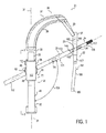
本発明の一実施形態において、髄内ロッド又は髄内釘22のような適切なインプラント又は埋め込み可能デバイス、適切なアラインメントスリーブ又はガイドスリーブ23、及び固定具、ラグネジ、又は止めネジ24のような適切なファスナとの併用に向けて、ステンレス鋼、チタン、合金、プラスチック、カーボンファイバ、又はいずれかの複合材料又はメッシュ材料のようなあらゆる適切な材料で製造することができる図1に示す装置又はインプラント挿入デバイス21を提供する。デバイス21及びガイドスリーブ23は、ロッド22が哺乳類の身体の骨の中に埋め込まれた後又はその埋め込みの前にロッド22の中にネジ24を入れるために使用することができる。髄内ロッド22は、ネジ24を受け入れるための開口25を含み、ネジ24が開口25内でロッド22に対してピボット回転することを許すように構成される。デバイス21は、第1の部分又は腕部分27と第2の部分又はターゲッティング部分28とを有する本体26を含む。一実施形態において、ターゲッティング部分28は細長い直線形であり、長手軸31に沿って延び、第1の部分又は底部分32と第2の部分又は上部分33とを有する。底部分32を第1の端部分32で表し、上部分33を第2の端部分33で表すことができる。腕部分又は腕27は、一実施形態において、アーチに似たような弓形であり、あらゆる適切な手段によってターゲッティング部分28の上部分33に結合又は接続された第1の端部分又は第1の肢部36と、髄内ロッド22の上部分又は近位端部分に結合するようになった第2の端部分、第2の肢部、又はコネクタ37とを有する。腕27は、ステンレス鋼、カーボンファイバ、プラスチック、又は複合材料のようなあらゆる適切な材料から製造することができ、一実施形態において、腕27の第1の端部分36から延びる弓形部材又は上部アーチ38と、上部アーチ38の上端からコネクタ37に延びる細長部材又はグースネック39とを含む。挿入デバイス21がロッド22に結合された場合に、図1に示すように、ターゲッティング部分28はロッド22から分離され、それに対してほぼ平行に延びている。一実施形態において、ターゲッティング部分28は、少なくともロッド22の開口25の周りでロッド22から分離される。
In one embodiment of the invention, a suitable implant or implantable device, such as an intramedullary rod or
ターゲッティング部分28は、ガイドスリーブ23を受け入れて、一実施形態ではターゲッティング部分、ロッド22、及び髄内ロッド22内の開口25に対してガイドスリーブをある角度範囲にわたってピボット回転させるためのターゲッティングアセンブリ又はターゲッティング機構46を含む。機構46は、ガイドスリーブ23、ファスナ24、及び一実施形態ではガイドスリーブ23とファスナ24の両方を髄内ロッド、より具体的にはロッド内の開口25に向けて指向させるように機能する。一実施形態において、機構及び従ってデバイス21は、ガイドスリーブ23、ファスナ24、又はガイドスリーブとファスナとの組合せをロッド、一実施形態ではロッド内の開口25に向けて、そのような角度範囲にわたって又はこの範囲にわたって連続的に指向させるように機能する。ガイドスリーブ、ファスナ、又はガイドスリーブとファスナとの組合せをそのようにピボット回転させるように、あらゆる適切な装置、機構、又はアセンブリを設けることができ、一実施形態において、ターゲッティングアセンブリは、長手軸31に沿って延びる第1の細長要素又はレール47と第2の細長要素又はレール48とを分離位置に含む(図2を参照されたい)。第1のレール47と第2のレール48は互いに平行に延び、互いから分離される。長手方向に延びるレール47、48の各々は、平坦な帯又は棒に類似するものとすることができる。各々は、ステンレス鋼、金属、複合材料、プラスチック、カーボンファイバ、又は他のファイバのようなあらゆる適切な材料から製造することができる。第1のレール47は、図3に示す内側平面51を有し、第2のレール48は、図4に示す内側平面52を有し、これらの平面は互いに対向し、互いに平行に延びている。
Targeting
ターゲッティングアセンブリ46は、第1及び第2のレール47、48によって摺動可能に担持することができるキャリッジアセンブリ又はキャリッジ56を含む。キャリッジ56は、ステンレス鋼のようなあらゆる適切な材料から製造され、レール47と48との間で長手軸31に沿って上下により大きくサイズが決定され、かつそのように成形されたスライド57を含む。例えば、図7及び図8に示す一実施形態において、スライド57は、第1のレール47の内側細長面51に摺動可能に係合する平坦な第1の側面58を含む。スライド57は、第2のレール48をスライド可能に受け入れて、レール47及び48に沿った長手移動中にスライド57の中心合わせを助けるための切欠き59を更に含む。スライドの切欠き59の基部を形成する平坦な第2の側面61は、第1の側面58と平行に延び、第2のレール48の内側細長面52に摺動可能に係合する。
The
ターゲッティング要素62は、スライド57によって回転可能に担持することができる。一実施形態において、ターゲッティング要素62は、第1の平坦な側面63と、この第1の側面63と平行に延びる反対の第2の平坦な側面64とを有するディスク、ホイール、又はあらゆる他の適切な形状のものとすることができる。一実施形態において、周囲円形面66は、スライド57の第1の側面58と第2の側面61の間の距離に実質的に等しい距離だけ分離された側面63と64の間で延びている。ターゲッティング要素の形状に基づいて、面66は、楕円形又は半円形を含むいずれかの他の適切な形状とすることができることが認められる。スライド57は、このディスクの第1及び第2の側面63、64がディスク62をスライド57のそれぞれの第1及び第2の側面58、61と実質的に同一平面に着座するように回転可能に受け入れるようにサイズが決定され、かつそのように成形された凹部67を含む。この点に関して、凹部67は、側面58及び61を通って延び、スライド57内で、ディスク62の半径に実質的に等しい半径を各々が有する反対第1の弓形面68と第2の弓形面69とによって部分的に形成される。スライド57は前面76と後面77を有し、ディスク62は、ディスクの周囲面66がスライド57から外向きにスライド57の前面76と後面77で延びるようにスライド57に対して直径がサイズ決定される。
The targeting
ディスク62は、ガイドスリーブ23を摺動可能に受け入れるようにディスク62を通して延びるボア又は通路81を有する。一実施形態において、通路81は、ディスク62を通してディスクの周囲面66上に設けられた対向する第1及び第2の開口部まで延びている。一実施形態において、通路81は、ディスク62の直径上に中心を置く軸82に沿って延びている。
The
ターゲッティング部分28は、キャリッジ56が、第1及び第2のレール47、48に沿って上下に移動される時に通路軸82の角度をターゲッティング部分の長手軸31に対して連続的に調節することを可能にするために、ターゲッティング部分に対してディスク62をピボット回転させるための装置を含む。このようにして、ロッド22に対するファスナ24の角度調節の連続範囲にわたって髄内ロッドに、より具体的にはロッド内の開口25に向けて通路軸82を指向させることができる。装置86は第1及び第2のレール47、48を含み、一実施形態において、第1のレール47の内側細長面51は、その内部に形成された第1の溝87と、その内部に形成された第2の溝88とを含む(図3及び図5を参照されたい)。第1及び第2の溝又はカム溝87、88は、互いに対してかつ長手軸31に対して傾斜される。一実施形態において、第1のカム溝又は軌道87は、レール47に沿って長手方向に上方に延びる時に細長面51の中心に向けて延び、細長面51上で第1のカム溝87に対して低位にある第2のカム溝又は軌道88は、第1のレール47上で長手方向に上方に延びる時に細長面51の中心に向けて同じく延びる。第1のレール47の内側細長面51に対向するディスク62の第1の側面63は、そこから外向きに延びる第1及び第2の離間した突起91、92を有する。一実施形態において、第1の突起又はカムピン91は、周囲面66に隣接する面63から延び、第2の突起又はカムピン92は、第1のカムピン91に対してディスク62の直径の反対の端にある周囲面66に隣接する面63から延びている。従って、第1のカムピン91と第2のカムピン93は、ディスク面63上で直径方向に対向する。円筒形カムピン91及び92の横断寸法又は直径は、それぞれのカム溝87及び88の幅を近似し、スライド57が第1のレール47と第2のレール48の間で摺動可能に担持される場合に、第1のカムピン91は、第1のカム溝87内に摺動可能に着座し、第2のカムピン92は、第2のカム溝88内に摺動可能に着座する。
The targeting
装置86は、第2のレール48の内側細長面52に沿って長手方向に延びる溝又はガイドスロット96を更に含む。追加の突起又はガイドピン97が、ディスク62の第2の側面64の中心から延び、第1のレール47と第2のレール48との間でのディスク62の回転を可能にするためのガイドスロット又はピボット回転スロット96内に着座する。円筒形ガイドピン97は、ガイドスロット96の幅を近似する直径を有し、ガイドスロットは、レール47及び48に沿ったキャリッジ56の長手移動にわたってディスク62の回転を可能にする長さを有する。
The
第1及び第2のレール47、48とディスク62とは、ロッド22の開口25の中にファスナ又はネジ24を挿入する角度を動的角度範囲で表すことができる角度範囲にわたって連続的に調節することを可能にするように、ディスクが第1及び第2のレールに沿って長手方向に摺動するときに、ターゲッティング要素又はディスク62を第1及び第2のレールに対してピボット回転させるように協働的に係合する特徴部を有する。一実施形態において、そのような協働的に係合する特徴部は、第1のレール47の細長面51、並びに細長面51内に形成された第1の溝87及び第2の溝88と、ディスク62の第1の側面63、並びにそれぞれの溝87、88内に摺動可能に着座するようにターゲッティング要素又はディスク62の側面から外向きに延びる第1及び第2の突起91、92とを含むことができる。一実施形態において、そのような協働的に係合する特徴部は、第2のレール48の細長面52、及び細長面52に沿って延びる溝又はガイドスロット96と、ディスク62の第2の側面64、及び溝又はスロット96内に摺動可能に着座するようにディスク62の第2の側面64から延びる突起又はガイドピン97とを更に含むことができる。
The first and
キャリッジ56は、第1のレール47の上を覆って延び、その反対側部で、スライド57の第1の面58のそれぞれの側部に固定する第1のカバー部分又はカバー101を含む。キャリッジ56は、第2のレール48の上を覆って延び、切欠き59の上を覆ってスライド57に接合する第2のカバー部分又はカバー102を更に含む。各々をステンレス鋼のようなあらゆる適切な材料から製造することができる第1及び第2のカバー101、102は、レール47及び48に沿ったキャリッジの長手移動にわたって第1及び第2のレール47、48をキャリッジ56内にそれぞれ捕捉するように機能する。
The
キャリッジ56とスライド57によって回転可能に担持されたディスク62とがターゲッティング部分28上に摺動可能に装着されると、スライド57の第1の面58及びディスク62の第1の側面63は、第1のレール47の内側細長面51に対向し、それに摺動可能に係合し、スライド57の第2の面61及びディスク62の第2の側面64は、第2のレール48の内側細長面52に対向し、それに摺動可能に係合する。ディスク62のガイドピン97は、キャリッジ56の長手移動にわたって第2のレール48の内側細長面52の中心線上に強制的に拘束され、ターゲッティング部分28上でのキャリッジ56の長手移動にわたって内側細長面51、52に対して直交し、その中心に配置された軸(図示せず)の回りにディスク62が回転又はピボット回転するのを可能にする。
When the
第1及び第2それぞれの傾斜カム溝87、88内への第1及び第2のカムピン91、92の捕捉は、キャリッジ56がターゲッティング部分に沿って長手方向に移動するときに、ディスク62が、レール47及び48、並びにターゲッティング部分28に対してピボット回転又は回転するのを加勢する。一実施形態において、キャリッジ56が、ターゲッティング部分28上の第1の位置からターゲッティング部分上の第2の位置まで長手方向に移動するときに、カムピン91及び92とそれぞれのカム溝87及び88との協働係合が、ディスク62及びディスク62を通って延びる通路81を連続的にかつ一実施形態では線形的に回転させる。通路81がターゲッティング部分に対してピボット回転又は回転する動的角度範囲とも表すことができる角度範囲は変更することができる。一実施形態ではそのような角度範囲は少なくとも5度であり、一実施形態ではそのような角度範囲は約10度であり、一実施形態ではそのような角度範囲は約20度であり、一実施形態ではそのような角度範囲は約30度であり、一実施形態ではそのような角度範囲は約40度であり、一実施形態ではそのような角度範囲は約50度であり、一実施形態ではそのような角度範囲は約60度であり、一実施形態ではそのような角度範囲は約70度であり、一実施形態ではそのような角度範囲は約80度である。図に示す一実施形態において、ディスク62及びディスク62を通って延びる通路81は、第1及び第2のレール47、48に対して、キャリッジ56が図1に示すようにターゲッティング部分28上の第1の位置又は上側位置にある時の約120度の角度103から、図2〜図4に示すようにターゲッティング部分28上の第2の位置又は中間位置にある時の約130度の角度103まで、更に図17に示すようにターゲッティング部分28上の第3の位置又は下側位置にある時の約140度の角度103までピボット回転又は回転する。この実施形態において、キャリッジ56の長手移動とディスク62の角度回転とは1対1であり、すなわち、線形である。
The capture of the first and second cam pins 91, 92 in the first and second
カム溝87及び88は、キャリッジ56がターゲッティング部分28に沿って移動するときに、ディスク62及び通路軸81のピボット回転が非線形であり、又はそのような移動の一部分に沿って不連続であり、すなわち、ディスク62が、その長手移動の一部中にはピボット回転又は回転するが、この長手移動のうちの他の部分ではピボット回転又は回転しないように構成することができることが認められる。更に、それぞれの内側細長面51、52上の第1及び第2のカム溝87、88の形状を適切に構成することにより、又はあらゆる他の適切な手段により、ディスク62の線形、非線形、及び不連続な回転又はピボット回転を与えることができることが認められる。
The
図1及び図17に示すように、レール47及び48、並びにターゲッティング部分28上のキャリッジ56の位置の一部又は全てにおいて通路81及び通路軸82の角度を示すために、レール47及び48のうちの少なくとも一方の外側に数字、線、目印、又は数字と線と目印との組合せを含むことができる適切な桁を設けることができる。明らかなように、通路81の角度は、ガイドスリーブ23及びガイドスリーブ23の端の上に装着された固定ネジ24のターゲッティング部分28に対する角度と同じである。
As shown in FIGS. 1 and 17, the
インプラント挿入デバイス22内には、ターゲッティング部分28に沿うある一定の位置又はいずれかの位置上にキャリッジ56を係止するための機構又はアセンブリを含めることができる。一実施形態において、拡大したヘッド108から延び、丸形端109を有するステム107を有する戻り止めピン106が、スライド57内に、この丸形端109が、スライド57の第2の面61(図7を参照されたい)から外向きに収縮可能に延びるように設けられる。戻り止めピン106の丸形端109は、第2のレール48の内側細長面52内に設けられた長手方向に分離された複数の戻り止め穴111のうちの1つに選択的に着座する。ディスク62及び通路81をあらゆる適切な角度間隔で係止することを可能にするように、戻り止め穴111の間にあらゆる適切な間隔を設けることができる。戻り止めピン106は、スライド57内でピンのヘッド108とプラグ113の間に配置されたバネ112により、丸形端109がスライド57の第2の面61から外向きに穴111のうちの1つの中に延びる延長位置に加勢される。ピン106、バネ112、及びプラグ113の各々は、スライド57の第1の面58から第2の面61に延びるボア(図示せず)の中に配置される。プラグ113は、そのようなボアの内部に固定され、図8に示すように、第1の面58と同一平面に着座する。
Within the
戻り止めピン106の丸形端109を丸形端がスライド57の第2の面61から外向きに延びる第1の位置又は延長位置から丸形端が第2の面61と同一平面に着座したか又はその内部に陥入した第2の位置又は収縮位置までバネ112の力に対して加勢するか又は移動するための係止要素又は他の適切な要素116が設けられる。一実施形態において、係止要素116は、スライド57の前面76において作動可能なレバー117と、スライド57の前面76内に設けられたボア119の中に延び込む円筒形ステム118とを有する。偏心ピン122が、ステム118の端の一方の側部から遠位に延び、ピン106のヘッド108の下側に係合する(図12を参照されたい)。レバー117が、前面76に対して約180度の角度だけ時計回りに回転されると、偏心ピン122は、戻り止めピン106をスライド57の内部に収縮させる。円筒形ピン又は回転制限器123が、スライド57の第1の面58からスライド57内のボア(図示せず)を通って延びて、係止要素116のステム118内に設けられた半環状凹部124に係合する。回転制限器123と凹部124の端面との係合は、係止要素116及びそのレバー117の回転移動を望ましい180度の移動角距離に制限する。更に、回転制限器123は、係止要素をスライドに固定させるように、係止要素116のステム118をスライド57の内部に保持するように機能する。
The
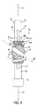
インプラント挿入デバイス21及び髄内ロッド22との併用のためのファスナ又はネジ24は、あらゆる適切なタイプのものとすることができ、一実施形態において、40ミリメートルから200ミリメートルまでの範囲にわたる長さと、2ミリメートルから20ミリメートルまでの範囲にわたる直径とを有する細長円筒形本体131又は螺旋ブレード(図示せず)から製造される。一実施形態において、ファスナは、ネジ山付き部分と平滑部分を有する本体から形成された固定ネジである。細長本体131は、ステンレス鋼のようなあらゆる適切な材料から形成することができ、いずれかの外側円柱面又は不規則形面133を有する近位部分132を含む。近位部分132には、面133を通って周方向に離間した位置に延びる複数の図示のものでは4つの長手方向に延びるスロット134を設けることができる。本体131の遠位部分136には、本体の尖鋭遠位端又は先端138まで延びる雄ネジ山137を設けることができる。これに代えて、本体131の遠位部分136は、不規則形又は平坦なものとすることができる(図示せず)。本体には、近位部分132から遠位端又は先端138まで本体131を通して長手方向に延びる中心ボア142を設けることができる。あらゆる適切なタイプの駆動ツールへの近位固定ネジの接続を容易にするために、中心ボア142の近位端に雌ネジ山143を設け、あらゆる適切なタイプの駆動ソケット144を形成することができる。本体131の近位端には、本体131の残りの部分の横断寸法よりも若干大きい横断寸法を有し、従って、哺乳類の身体の適切な骨の内部でのロッド22及びネジ24の作動及び使用中に髄内ロッド22の開口25の内部におけるネジ24の長手移動を制限する適切なフランジ付きヘッド146を形成することができる。
The fastener or screw 24 for use with the
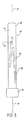
ガイドスリーブ又はアラインメントスリーブ23は、あらゆる適切なタイプのものとすることができ、一実施形態において、ステンレス鋼のようなあらゆる適切な材料から製造された円柱部材又は本体151から形成される。ガイドスリーブ又はオーバーチューブ23の本体151は、近位部分152と遠位部分153とを有する。少なくとも近位部分152は円形断面を有し、一実施形態において、本体151の全長の断面が円形である。ディスク62の通路81は、本体151の断面寸法を近似し、かつそれよりも少なくとも若干大きい直径を有し、従って、本体151のいずれかの円形断面の直径を近似し、かつそれよりも若干大きい。本体151には、共形でチューブ状のものであるように本体151を通して延びる中心ボア154を設けることができる。ネジ24をガイドスリーブ23の遠位端に接続することを可能にし、更に骨の内部へのネジ24の配置中にガイドスリーブによってネジ24を回転又は駆動することを可能にするために、本体151の遠位端は、ネジ24の近位端に設けられた雌ネジ山143と協働的に接続するための適切な駆動部分又は駆動要素(図示せず)、例えば、ねじ山付き延長部を含むことができる。
The guide sleeve or
上記に解説したインプラント挿入デバイス21との併用に適する埋め込み可能医療デバイスの一実施形態は、図13〜図16に示す装置、デバイス、又は髄内ロッド22である。ロッド22は、哺乳類の身体のあらゆる骨の中に使用することができるが、一実施形態において、ロッド22は、大腿骨の中に使用するためのものであり、従って、大腿骨釘22と呼ぶことができる。2012年12月14日に出願され、全体の内容が引用によって本明細書に組み込まれている「係止調節機構を有する埋め込み可能デバイス、及びそれを使用する方法(Implantable Device with Locking Adjustment Mechanism and Method for Using Same)」という名称の米国本出願第13/716,079号明細書に記載されている釘22は、長手軸又は中心軸162に沿って延び、かつ近位部分、近位端、又はヘッド166と、中心部分又はネック167と、遠位先端169において終端する遠位部分又はシャフト168とを有することができる細長本体161を含む。図には釘22を概略的にしか例示しておらず、この場合に、ヘッド166、ネック167、及びシャフト168は、必ずしも正確な縮尺に示したものではない。本体161は、大腿骨又はロッドを挿入される他の骨の髄管の長さに沿ってロッド22を位置合わせするように、シャフト又はステム168のうちの少なくとも1つの部分で湾曲させることができる。細長本体161には、哺乳類の身体の大腿骨又は他の骨内へのロッドの挿入中にガイド線(図示せず)に沿ってロッドが摺動することを可能にするための長手方向に延びる通路又はボア176を設けることができる。更に、少なくとも1つの遠位ファスナ又は遠位ネジ(図示せず)を受け入れるように、先細先端169に隣接するステム168の遠位端部分内に少なくとも1つのボア177を設けることができる。
One embodiment of an implantable medical device suitable for use with the
ロッド22のヘッド166は、近位固定ネジ24を釘ヘッド166に対する第1の角度付き位置から釘ヘッドに対する第2の角度付き位置に選択的にピボット回転させるための作動又は調節の機構又はアセンブリ181を含むことができる。この点に関して、図16に示すように、ヘッド166の近位端内の近位開口部183と連通する長手方向に延びる近位凹部182を形成するように、釘22の近位部分の中心通路176を中空にすることができる。近位凹部182は、近位開口部183に隣接する近位ネジ山付き部分又は雌ネジ山付き部分182aと、円形中心部分182bと、一実施形態では断面が非円形であり、本明細書では場合によって領域分割円形部分又は領域分割部分182cで表す遠位部分182cとを有することができる。チューブ状ヘッド166は、形状が実質的に環状であり、近位凹部182によって形成された外壁186によって形成される。
The
ヘッド166には、長手軸162に対してある角度で傾斜した横断軸188に沿って延びる少なくとも1つの開口25が設けられる。ヘッド166は、細長通路176の近位凹部182とは別個であるが、部分的に近位凹部182によって形成された開口25内にファスナ又はネジ24を受け入れるようになっている。一実施形態において、ヘッド166に単一の開口25が設けられる。開口25は、壁186の一方の側部上に設けられた第1の横断開口部又は横方向横断開口部191と、壁186の他方の側部上に設けられた第2の横断開口部又は中間横断開口部192とによって形成することができる。横断軸188は、開口25の中心に置かれ、長手軸に対してある角度で、一実施形態ではヘッド開口25の遠位にあるヘッド166の部分から測定して約140度の角度で延びることができる。
The
近位固定ネジ24をピボット回転させるための作動機構又は調節機構181はあらゆる適切なタイプのものとすることができるが、一実施形態において、機構181は、挿入要素又は挿入スリーブ196と、ネジ山付き要素又は制御要素197と、アラインメントネジ又は位置決めネジ198と、係止機構199とを含む。別途示さない限り、これらの構成要素の各々は、ステンレス鋼のようなあらゆる適切な材料で製造することができる。
Although the actuation or
幅広い分類の細長要素又は可動要素の一実施形態における一例であるスリーブ196は、近位部分又は端部分に円形の環又はリング201を有する細長チューブ状の要素又は部材から形成することができる。リップ202が、凹部203によって環201から近位に離間している。環201は、スリーブ196の周りを形成し、形状が実質的に円形である。スリーブ196には、スリーブ96の遠位部分207を形成するように、環201の遠位に延びる細長切欠き206が設けられる。一実施形態において、遠位部分207は断面が非円形であり、一実施形態において、ヘッド近位凹部182の領域分割部分182cの断面とほぼ対応する断面を有する。スリーブ196の遠位部分207は、ヘッド166の近位凹部の領域分割円形部分182cの内部で長手方向に摺動可能に移動するようにサイズが決定され、かつそのように成形される。スリーブ196の環201は、ヘッド近位凹部182の中心部分182bの内部で長手方向に摺動可能に移動するように外部がサイズ決定され、かつそのように成形される。通路又はボア208は、スリーブ196の長さだけ延びている。一実施形態において、ボア208は、その近位部分において内部にネジ山が付けられる。スリーブ196には、その遠位部分207内に、ファスナ又は固定ネジ24を受け入れるようになった少なくとも1つの開口209が設けられる。開口209は、ボア208とは別個のものであり、ボア208は、開口209を通って延びる。一実施形態において、スリーブ196には、単一の開口209が設けられる。
An
制御要素、可動要素、及びネジ山付き要素を含む幅広い分類の要素の一実施形態における一例である回転可能制御要素197は、ヘッド166によって担持され、調節機構181にヘッド166に対して固定ネジ24をピボット回転させるように近位開口部183においてアクセス可能である。制御要素はあらゆる適切なタイプのものとすることができ、かつ一実施形態では環状のものであってヘッド166の近位凹部182のネジ山付き部分182aとの螺合に向けて外部にネジ山を付けることができる第1の部分又は近位部分216を有するスピンドル、ネジ、又はウォームギア197を含む。ウォームギア197の遠位部分又は端部分は、雄ネジ山付き近位部分216から環状凹部215によって離間した環状フランジ217を含むことができる。フランジ217は、スリーブ196の凹部203の内部にちょうど着座するように直径がサイズ決定され、かつそのように成形される。同様に、ウォームギア197の環状凹部215は、スリーブ196のリップ202をちょうど受け入れるように直径がサイズ決定され、かつそのように成形される。このようにしてウォームギア197がスリーブ196に結合又は接続されると、ウォームギアの中心軸は、スリーブ196の中心軸と一致し、ウォームギアは、スリーブ196に対して長手方向に固定又は係止されるが、ウォームギア197は、スリーブ196に対してそのような中心軸及び長手軸162の回りに回転可能である。
The
ウォームギア197は、そのような要素がヘッド166の内部に配置された場合に、スリーブの長手の位置及び移動を制御し、この点に関して、ウォームギアに、それを通して長手方向に延び、あらゆる適切なタイプ又は形状の非円形断面を有する中心通路又は駆動ソケット218を設けることができる。スリーブ196及びウォームギア197が釘ヘッド166の内部にそのように配置されると、ウォームギア197の駆動ソケット218の内部に着座した適切な駆動要素が、ヘッド近位凹部182の雌ネジ山付き部分182aの内部の近位又は遠位でウォームギア197を螺動又は回転させるように機能することができる。同時に、ヘッド166の内部でのウォームギア197のそのような前進又は後退は、スリーブ196をヘッド近位凹部182の中心部分182b及び領域分割部分182c内でウォームギア197の長手移動と1対1で前進又は後退させる。
The
係止機構のアセンブリ又はデバイス199は、ウォームギア197に結合され、係止機構が図16に示す第1の位置にある時に、ヘッド166に対するウォームギアの回転を不可能にし、係止機構が第2の位置にある時に(図示せず)、ヘッド166に対するウォームギア197の回転を可能にするように構成される。係止機構199が、ヘッド166内でウォームギア197を回転可能に係止及び係止解除するためのあらゆる適切な構成及び構造を有することができることは認められるが、一実施形態において、係止機構は、第1の係止要素221と第2の係止要素222とを含む。第2の係止要素222は、この第2の係止要素が第1の係止要素と回転可能に係止されるように第2の係止要素222の近く面上で周方向に離間した複数の突起又は回し金222aが第2の係止要素222の遠位面上で周方向に離間した複数の突起又は回し金221aに協働的に係合する第1の位置と、第2の係止要素が第1の係止要素に対して回転可能であるように第2の係止要素222の周方向に離間した複数の回し金が第1の係止要素221の周方向に離間した複数の回し金から切断される第2の位置との間で長手方向に移動可能である。一実施形態において、第1の係止要素は、環状形状のものとすることができ、ヘッド166内の近位凹部182のネジ山付き部分182aに螺合係合するように外部にネジ山を付け、直径をサイズ決定することができる環状の要素又はナットとすることができる。一実施形態において、第2の係止要素222は環状形状のものとすることができ、環状の要素又はワッシャーとすることができる。
The locking mechanism assembly or
係止機構199は、近位端から長手方向に内向きに延びる駆動ソケット224を有するドライバ要素又はドライバ223を更に含むことができる。ソケット224は、適切なツールによって係合された時にドライバ223の回転をもたらすように機能することができるように、形状が非円形である断面を有する。長手方向に延びるボア226が、駆動ソケット224から遠位にドライバ223の残りの部分を通して延びている。ドライバ223は、ナット221及びワッシャー222を通って延び、ワッシャー222は、溶接のようなあらゆる適切な手段によってドライバ223の近位部分に固定される。ナット221はドライバ223に固定されず、従って、ドライバに対して長手方向に移動可能である。ワッシャー222をナット221に対する第1の位置又は係止位置に向けて加勢するための手段が係止機構199に含まれ、この手段は、ドライバ223の周囲に配置され、ドライバ223の近位端に設けられた第1のフランジ225と、ナット221の遠位端上に設けられた第2のフランジとに係合する適切なバネ、例えば、環状波バネ227を含むことができる。バネ227は、係止機構199をワッシャー222がナット221に対して回転可能に係止される図16に示す第1の位置又は静止位置に向けて加勢する。
The
ドライバ223が、例えば、ドライバ223の駆動ソケット224内への適切な駆動ツールの挿入により、かつツール及び従ってドライバ223に対して遠位横方向の長手の力の作用により長手方向に遠位横方向に加勢された場合には、ドライバ223の近位部分に堅固に固定されたワッシャー222は、バネ227の力に対してナット221から長手方向に移動され、それによってワッシャー222の回し金がナット221の回し金から分離及び切断され、ドライバ223とワッシャー222との組合せユニットをナット221に対して回転させることができる。
The
位置決めネジ198は、あらゆる適切なタイプのものとすることができ、一実施形態では共形の円筒形であり、外部にネジ山が付けられる。位置決めネジ198は、丸形遠位端231と、近位端に設けられた適切な駆動ソケット232とを含むことができる。そのような位置決めネジは、スリーブボア208のネジ山付き近位部分に螺合係合するように、ドライバ223の駆動ソケット224及びボア226を長手方向に通してスリーブ196のボア208の中に入ることができるように直径がサイズ決定される。
The
インプラント挿入デバイス21は、作動及び使用中に、釘22を骨の内部に例えば上述のようなあらゆる適切な方式で配置するために利用することができる。本発明の1つの方法では、釘22を哺乳類の身体の骨の中に挿入するように、デバイスの端部分又はコネクタが釘のヘッド166にあらゆる適切な方式で結合される。1つの方法では、最初にガイド線が骨の中に導入され、次に、釘が、骨内への適正な配置及び位置決めに向けてガイド線の近位端の上で螺合する。この点に関して、ガイド線の近位端は、細長本体161の通路176を通して、スリーブ196のボア208及びウォームギア197の駆動ソケット218によって調節機構181を通して、かつドライバ223のボア226及び駆動ソケット224によって係止機構199を通して挿入することができる。釘22が骨の内部に適正に配置された後に、ガイド線は、釘22から近位開口部183を通して取り出される。
The
固定ネジ24のような適切なファスナを横方向横断開口部191、スリーブ196の開口209、及び中間横断開口部192によってヘッド166を通して導入し、骨の内部に適正に配置することができる。この点に関して、固定ネジ24は、例えば、上述のように適切な方式でガイドスリーブ23の遠位端を通して挿入され、一実施形態において、ネジ24は、ガイドスリーブ23の遠位端上で装着されるようにガイドスリーブ23の遠位端から延びる。一実施形態において、ネジは、ガイドスリーブ23と同軸で延びる。ガイドスリーブ23は、そこを通してのネジ24の挿入の前に、ディスク62の通路81を通して導入される。ディスク通路81を通してのガイドスリーブ23の更に別の前進は、ネジ24の遠位先端169を釘22のヘッド166内の開口25内にターゲット設定する。レール47及び48上のキャリッジ56の位置に関わらず、ガイドスリーブ23と固定ネジ24とは位置合わせし、釘22の開口25に向けられる。この点に関して、ターゲッティングアセンブリ46は、ディスク62及びディスク62に担持されたガイドスリーブ23をターゲッティング部分28に対して回転させ、ガイドスリーブが髄内釘22の開口25に対してピボット回転される時に、同時にガイドスリーブ23をターゲッティング部分28に対して長手方向に移動するように構成される。
A suitable fastener, such as a
固定ネジ24が、ガイドスリーブ23の補助を受けて釘22の開口25を通して導入され、哺乳類の身体の骨の内部に部分的に又は完全にのいずれかで配置された状態で、釘22内の調節機構181を用いて、固定ネジ24は、ヘッド166及び釘の中心軸162に対してある角度範囲にわたってピボット回転させることができる。この点に関して、制御要素又はウォームギア197は、インプラント挿入デバイス21のコネクタ37及びヘッド166の近位端にある近位開口部183を通してアクセスすることができ、例えば、コネクタ37及び開口部183を通しての近位凹部182及びナット221の駆動ソケット224内への適切な駆動ツール(図示せず)の挿入によってそうすることができる。係止機構199と、この係止機構のドライバ223と1対1で回転するウォームギア197とを回転可能に係止解除し、ヘッド166の内部でのスリーブ197の長手移動を可能にするために、駆動ツールは、駆動ソケット224内でヘッド166に対して遠位に加勢され、それによってドライバ223は、軸162に沿って長手方向に移動し、従って、ワッシャー222上の係止回し金を上記に解説した方式でナット221の係止回し金から長手方向に分離かつ切断させる。ドライバ223とワッシャー222との組合せユニットが係止機構199の第2の位置に移動された状態で、駆動ツールは、ナット221及びヘッド166から自由にドライバ223を回転させるように使用することができ、それによってウォームギア197は回転し、従って、ウォームギア及びウォームギアに結合されたスリーブ196は、凹部192の内部で長手方向に移動する。この点に関して、固定ネジ24のうちで開口209を通して延びる部分は、スリーブ196によって制限されるので、ヘッド166に対するスリーブの長手移動は、固定ネジをヘッド166の中間横断開口部192の回りにピボット回転させる。このようにして、作動アセンブリ181は、釘開口25の横断軸188を変更するように機能する。
A
一実施形態において、固定ネジ24は、例えば、図13〜図16に示すように釘22のヘッド166に対して約120度の角度にある第1の位置又は第1の端位置から、例えば、図18に示すようにヘッドに対して140度の角度にある第2の位置又は第2の端位置までピボット回転させることができる。一実施形態において、ターゲッティングアセンブリ46は、固定ネジ24を髄内釘22に対してピボット回転させることができる角度範囲と同じ角度範囲にわたってディスク62及びこのディスクを通して延びる通路81をピボット回転又は回転させる。キャリッジ56の位置は、ガイドスリーブ23がデバイス21によって支持されたままに留まり、手順中に固定ネジ24と同じく角度付けされるように、ヘッド24の内部のネジ24の角度位置の調節中に又はそれと比例してレール47及び48上で移動することができる。
In one embodiment, the securing
固定ネジ24が釘22に対して望ましく角度付けされた状態で、位置決めネジ198は、ドライバ223を通してスリーブボア208の雌ネジ山付き近位部分208a内に挿入され、位置決めネジの丸形端231が固定ネジ24に係合して固定ネジをその望ましい角度付き位置に係止し、開口25及び209の内部でのネジ24の更に別のピボット回転又は回転を抑制するまで遠位に前進させることができる。一実施形態において、位置決めネジ198の丸形端231は、釘ヘッド166の内部でのネジ24の回転可能係止を強化するために、固定ネジ24の長手スロット204のうちの1つの内部に着座する。
With the fixing
ガイドスリーブ23がディスクの通路81に配置された場合のターゲッティング部分28に対するディスク62のピボット回転は、固定ネジが釘開口25内に挿入される角度をある角度範囲にわたって連続的に調節することを可能にする。その結果、ガイドスリーブ23及び固定ネジ24を釘ヘッド166及びヘッド166内の開口25に向ける角度を変更するのに、現在提供されているいくつかのインプラント挿入デバイスの場合にそうであるようにガイドスリーブ23をターゲッティング部分28から引き抜く必要がないか、又は他のインプラント挿入システムの場合にそうであるようにガイドスリーブ23に対して異なる固定角度を有する第2のインプラント挿入デバイスを釘22に結合する必要がない。
The pivoting of the
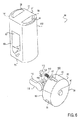
釘22のような適切な埋め込み可能デバイスに結合するのに適切な本発明のターゲッティングデバイス又はジグ21のコネクタ37の一実施形態を図19及び図20に例示している。これらの図に示すターゲッティングデバイス又はジグ21は、遠位先端にグースネック39を有し、遠位端にコネクタ17を有する遠位部分又は腕27を含む。一実施形態において、腕27は、コネクタ17で終端し、コネクタ17は、コネクタ要素又は締結要素243を受け入れるためのボア又はソケット242が設けられた円筒形又はチューブ状のハウジング241を含むことができる。ハウジング241は、締結要素243をソケット内に挿入することを可能にするためのソケット242への近位開口部又は上側開口部247が設けられた近位端又は上端246と、釘ヘッド166に固定するように締結要素243の一部分が通って延びることができる遠位開口又は下側開口部249とを有することができる。
One embodiment of a
ハウジング242の下端248は、釘ヘッド166の近位端及び近位開口部183と協働的に係合するようにサイズ決定され、かつそのように成形される。一実施形態において、下側開口部249は、釘ヘッド166の近位開口部183の直径を近似する直径を有する。ハウジング241には、ハウジング241、従って、ターゲッティングデバイス21を釘ヘッド166及び従って釘22と係止し、かつ位置合わせするように、釘ヘッド166の近位端上に設けられた凹部又はノッチ252の内部にちょうど着座するように協働的にサイズ決定され、かつそのように成形された位置合わせ要素又は鉤251を更に設けることができる。
The
締結要素243は、あらゆる適切なタイプのものとすることができ、一実施形態において、ハウジング241内のボア又はソケット242の直径に非常に近いが、それよりも若干小さい直径を有する円筒形のナット243である。ナット243には、ナット243を通して延びる貫通ボア256を設けることができる。ボア256の近位端には、ハウジング241の内部でナット243を回転させるためのあらゆる適切な駆動要素(図示せず)を受け入れるための適切な駆動ソケット257を設けることができる。ナット243の遠位端258の外部は、環状面259における小さい直径まで狭窄し、雄ネジ山261が設けられる。雄ネジ山付き遠位端258は、釘ヘッド166の近位端における雌ネジ山付き部分182と協働的に係合して螺合する。ハウジング241には、ナット243の環状面259を受け入れて、それに係合するための環状座部又は環状面262がソケット242内に設けられる。
The
ターゲッティングアセンブリ又はターゲッティングデバイス21を釘22に固定させる時に、ナット243は、ハウジング241のソケット242内に入れられ、ハウジングは、ハウジング鉤251の位置が釘ヘッド166内のノッチ252と位置合わせするように、ここでもまた、釘ヘッド166の近位端で加勢される。ナット243の雄ネジ山261を釘ヘッド166の近位開口部183内に捩じ込むように、適切な駆動ツールがナット243の駆動ソケット257内に挿入される。ハウジング241は、ナット243の環状面259とハウジング241の環状座部262との係合により、釘ヘッド166の近位端に対して加勢され、そこに固定される。
When securing the targeting assembly or targeting
釘22のヘッド166へのターゲッティングデバイス21のコネクタ17の固定により、釘の係止機構199が自動的に係止解除され、それによってウォームギア197の回転、従って、スリーブ96の移動が可能になり、かつ釘22に対するネジ24のピボット回転が可能になる。一実施形態において、ナット243の遠位端258は、そのような端258から遠位に突出するか又は延びて、一実施形態において、図19及び図20において長手軸162と共直線であるか又は同じであるナット243の中心長手軸上に中心を置く延長部又は円筒形延長部266のようなあらゆる適切なタイプの適切な作動要素を有する。延長部266は、雄ネジ山付き遠位端258の外径よりも小さい外部直径を有することができる。延長部266の外径は、ターゲッティングデバイス21のナット243が釘ヘッド166の近位端にねじ込まれる時に、係止機構のドライバ223のフランジ225に係合し、同時にドライバ223を図19に示す第1の位置又は係止位置から図20に示す第2の位置又は係止解除位置まで遠位に移動するように、係止機構199のナット221の内径よりも小さいとすることができる。作動要素は、シリンダ、ピストン、又はプランジャーとすることができ、雄ネジ山が不在のものとすることができる。作動要素は、ナット243の中心長手軸に関して断面が非円形であるもののような他の形状を有することができる。
By securing the connector 17 of the targeting
上述の方式では、釘へのターゲッティングデバイス21の結合又は接続だけで釘の係止機構199が係止解除され、釘の横断開口25、従って、ファスナ又はネジ24の角度を釘の中心軸162に対して調節することが可能になる。上述のように、ファスナ24のピボット回転は、ナット243及びコネクタ37のハウジング241を通してドライバ223の駆動ソケット224内に適切な駆動要素を挿入することによってもたらされる。釘22又は他の埋め込み可能デバイスへのターゲッティングアセンブリ21のそのような接続の前には、横断開口25又はその中にあるいずれのファスナ24の角度調節をも不可能にするために、係止機構199はその係止位置にある。
In the manner described above, the
本発明のインプラント挿入デバイスと共に、他の髄内釘及び他のインプラントを利用することができることが認められる。ガイドスリーブをインプラント挿入デバイスに対して連続角度範囲にわたってピボット回転させる上で、他の構成又は設計のインプラント挿入デバイスを提供し、本発明の範囲にあるとすることができることも認められる。ガイドスリーブをインプラント挿入デバイスに対して回転させ、ガイドスリーブがインプラントに対して又はより具体的にはインプラント内の開口に対してピボット回転される時に、ガイドスリーブをインプラント挿入デバイスに対して長手方向に同時に移動する他の構成又は設計のインプラント挿入デバイスを提供し、本発明の範囲にあるとすることができることが更に認められる。 It will be appreciated that other intramedullary nails and other implants can be utilized with the implant insertion device of the present invention. It will also be appreciated that other configurations or designs of implant insertion devices may be provided and within the scope of the present invention for pivoting the guide sleeve relative to the implant insertion device over a continuous angular range. When the guide sleeve is rotated relative to the implant insertion device and the guide sleeve is pivoted relative to the implant or more specifically relative to the opening in the implant, the guide sleeve is longitudinally relative to the implant insertion device. It is further appreciated that other configurations or designs of implant insertion devices that move simultaneously may be provided and within the scope of the present invention.
Claims (13)
前記髄内ロッドの近位端に結合するように構成されている第1の部分と前記髄内ロッドから離間した位置で延びる第2の部分とを有する本体を備え、
前記第2の部分は、前記ガイドスリーブを受け入れる通路を有するターゲッティングアセンブリを備え、
該ターゲッティングアセンブリは、前記ガイドスリーブの或る角度範囲内にわたる連続的な調整の間、前記ガイドスリーブが前記第2の部分上を長手方向に移動させられるにつれて、角度方向と長手方向の協働した動きを生じさせながら、前記ガイドスリーブを前記開口に向けるように機能する、
ことを特徴とするインプラント挿入デバイス。 An implant insertion device for use with an intramedullary rod having a proximal end and an opening for receiving a fastener, and a guide sleeve for inserting the fastener into the opening of the intramedullary rod,
A body having a first portion configured to couple to a proximal end of the intramedullary rod and a second portion extending away from the intramedullary rod;
The second portion comprises a targeting assembly having a passage for receiving the guide sleeve;
The targeting assembly cooperates angularly and longitudinally as the guide sleeve is moved longitudinally over the second portion during continuous adjustment of the guide sleeve over a range of angles. Functions to direct the guide sleeve toward the opening while causing movement;
An implant insertion device characterized by that.
請求項1に記載のインプラント挿入デバイス。 The angular range is selected from the group consisting of at least 5 degrees, about 10 degrees, about 20 degrees, about 30 degrees, and about 40 degrees.
The implant insertion device according to claim 1.
前記細長い要素及びターゲッティング要素が、前記ターゲッティング要素が前記細長い部材上を長手方向に動かされるとき、前記ガイドスリーブを連続的に前記開口に向ける、
請求項1に記載のインプラント挿入デバイス。 The targeting assembly comprises an elongate member and a targeting element movable along the elongate member and provided with a passage for receiving the guide sleeve;
The elongate element and the targeting element continuously direct the guide sleeve toward the opening as the targeting element is moved longitudinally over the elongate member;
The implant insertion device according to claim 1.
該髄内ロッドが、長手方向軸線に沿って延び、ステムとヘッドとを有し、前記ヘッドが近位端にあり且つ開口を備え、該開口が前記長手方向軸線に対してある角度の軸線に沿って延び前記ファスナを受け入れるように構成され、
調節機構が、前記ファスナを前記ヘッドに対する第1の角度位置から該ヘッドに対する第2の角度位置までピボット回転させるように、前記ヘッドによって支持されている、
請求項1に記載のインプラント挿入デバイス。 In combination with the intramedullary rod,
The intramedullary rod extends along a longitudinal axis, has a stem and a head, the head is at a proximal end and includes an opening, the opening being at an axis at an angle with respect to the longitudinal axis Configured to extend along and receive the fasteners,
An adjustment mechanism is supported by the head to pivot the fastener from a first angular position relative to the head to a second angular position relative to the head.
The implant insertion device according to claim 1.
前記髄内ロッドの近位端に結合するようになった第1の部分と、前記開口の近傍で前記髄内ロッドから離間した位置で延びる第2の部分と、前記第2の部分が、前記ガイドスリーブを受入れる通路を有するターゲッティングアセンブリを備え、
該ターゲッティングアセンブリは、前記第2の部分に対する前記ガイドスリーブの角度が或る角度範囲内にわたって連続的に調整されるにつれて、前記ガイドスリーブを前記開口に向けるように、前記第2の部分に対する前記ガイドスリーブの角度方向と長手方向の協働した動きを生じさせる、
ことを特徴とするインプラント挿入デバイス。 An implant insertion device for use with an intramedullary rod having a proximal end and an opening for receiving a fastener, and a guide sleeve for inserting the fastener into the opening of the intramedullary rod,
A first portion adapted to couple to a proximal end of the intramedullary rod; a second portion extending away from the intramedullary rod in the vicinity of the opening; and the second portion comprising: A targeting assembly having a passage for receiving a guide sleeve;
The targeting assembly includes a guide for the second portion to direct the guide sleeve toward the opening as the angle of the guide sleeve relative to the second portion is continuously adjusted over a range of angles. Create a coordinated movement of the sleeve in the angular and longitudinal direction,
An implant insertion device characterized by that.
請求項5に記載のインプラント挿入デバイス。 The angular range is selected from the group consisting of at least 5 degrees, about 10 degrees, 20 degrees, 30 degrees, and 40 degrees.
The implant insertion device according to claim 5.
請求項5に記載のインプラント挿入デバイス。 The targeting assembly includes an elongate element and a targeting element that is movable relative to the elongate element and includes a passage that receives the guide sleeve, the elongate member and the targeting member being operatively engageable. Having a feature and when the angle of the guide sleeve relative to the elongate member is adjusted within a range of angles, the targeting member is moved longitudinally over the elongate member and the passage and continuously directed toward the opening Configured as
The implant insertion device according to claim 5 .
前記ターゲッティング要素は、前記細長面に対向する側面を有し、前記協働して係合する特徴部は、前記細長面に設けられ互いに対して傾いた第1および第2の溝を有し、前記側面から延び、かつ前記第1及び第2の溝にそれぞれ着座する第1及び第2の離間した突起を有し、
それによって前記ターゲッティング要素が前記細長面に沿って長手方向に動くとき、前記第1及び第2の溝での前記第1及び第2の突起の移動が、前記ターゲッティング要素を前記髄内ロッドの開口に対してピボット回転させる、
請求項7に記載のインプラント挿入デバイス。 The targeting element has an elongated surface;
The targeting element has a side opposite the elongated surface, and the cooperating features include first and second grooves provided on the elongated surface and inclined relative to each other; First and second spaced apart projections extending from the side surface and seated in the first and second grooves, respectively;
Thereby, when the targeting element moves longitudinally along the elongated surface, movement of the first and second projections in the first and second grooves causes the targeting element to open the opening of the intramedullary rod. Pivot with respect to,
The implant insertion device according to claim 7 .
請求項8に記載のインプラント挿入デバイス。 The targeting element comprises an additional elongated surface, the targeting element is disposed between the first elongated surface and the additional elongated surface, and the additional elongated surface is provided with a longitudinally extending groove. The targeting element has an additional side opposite the additional elongated surface, and an additional protrusion extending from the additional side and seated in the longitudinally extending groove, the additional protrusion being Rotating in the longitudinally extending groove as the targeting element is moved longitudinally along the elongated surface and the additional elongated surface;
The implant insertion device according to claim 8 .
第1の端部分と第2の端部分とを有する離間した長手方向に延びる第1及び第2のレールと、
前記第1及び第2のレールの第2の端部分に固定された第1の先端と、前記髄内ロッドの近位端に結合するように構成された第2の先端とを有するアームと、
前記第1及び第2のレールの間に摺動可能に支持された前記ガイドスリーブを受け入れるための通路を有するターゲッティング要素と、を備え、
前記第1及び第2のレールと前記ターゲッティング要素は、前記ファスナが前記髄内ロッドの開口内に挿入される角度を動的角度範囲にわたって連続的に調節することを可能にするように、前記ターゲッティング要素が前記第1及び第2のレールに沿って長手方向に摺動するときに前記ターゲッティング要素を前記第1及び第2のレールに対してピボット回転させるように協働的に係合する特徴部を有する、
ことを特徴とするインプラント挿入デバイス。 An implant insertion device used with an intramedullary rod having a proximal end and an opening for receiving a fastener, and a guide sleeve for inserting the fastener into the opening of the intramedullary rod,
Spaced apart longitudinally extending first and second rails having a first end portion and a second end portion;
An arm having a first tip secured to a second end portion of the first and second rails, and a second tip configured to couple to a proximal end of the intramedullary rod;
A targeting element having a passage for receiving the guide sleeve slidably supported between the first and second rails;
The first and second rails and the targeting element are adapted to allow the fastener to be continuously adjusted over a dynamic angular range of the angle at which the fastener is inserted into the opening of the intramedullary rod. A feature that cooperatively engages the targeting element to pivot relative to the first and second rails as the element slides longitudinally along the first and second rails. Having
An implant insertion device characterized by that.
請求項10に記載のインプラント挿入デバイス。 The angular range is selected from the group consisting of at least 5 degrees, 10 degrees, 20 degrees, 30 degrees, and 40 degrees;
The implant insertion device according to claim 10.
請求項10に記載のインプラント挿入デバイス。 The cooperatively engaging feature includes an elongated surface on the first rail provided with first and second grooves that are inclined relative to each other, and the targeting element is opposite the elongated surface. And a first and second spaced apart projections extending from the side and seating in the first and second grooves, respectively, so that the targeting element is longitudinal along the elongated surface Movement of the first and second protrusions in the first and second grooves causes the targeting element to pivot relative to the opening of the intramedullary rod.
The implant insertion device according to claim 10.
請求項12に記載のインプラント挿入デバイス。 The cooperatively engaging feature includes an elongated surface on the second rail, and the targeting element is disposed between the elongated surface of the first rail and the elongated surface of the second rail. The elongated surface of the second rail is provided with a longitudinally extending groove, the targeting element extending from the additional side opposite the elongated surface of the second rail, and An additional protrusion seated in the longitudinally extending groove, wherein the additional protrusion when the targeting element is moved longitudinally along the elongated surface of the first and second rails Rotating in a groove extending in the direction,
The implant insertion device according to claim 12.
Applications Claiming Priority (5)
| Application Number | Priority Date | Filing Date | Title |
|---|---|---|---|
| US201261596583P | 2012-02-08 | 2012-02-08 | |
| US61/596,583 | 2012-02-08 | ||
| US13/763,599 US9861418B2 (en) | 2012-02-08 | 2013-02-08 | Implant insertion device with continuously adjustable targeting assembly |
| PCT/US2013/025455 WO2013120034A1 (en) | 2012-02-08 | 2013-02-08 | Implant insertion device with continuously adjustable targeting assembly |
| US13/763,599 | 2013-02-08 |
Publications (3)
| Publication Number | Publication Date |
|---|---|
| JP2015507972A JP2015507972A (en) | 2015-03-16 |
| JP2015507972A5 JP2015507972A5 (en) | 2016-03-31 |
| JP6247644B2 true JP6247644B2 (en) | 2017-12-13 |
Family
ID=47755004
Family Applications (1)
| Application Number | Title | Priority Date | Filing Date |
|---|---|---|---|
| JP2014556760A Active JP6247644B2 (en) | 2012-02-08 | 2013-02-08 | Implant insertion device having a continuously adjustable targeting assembly |
Country Status (4)
| Country | Link |
|---|---|
| US (1) | US9861418B2 (en) |
| JP (1) | JP6247644B2 (en) |
| CN (1) | CN104411259B (en) |
| WO (1) | WO2013120034A1 (en) |
Families Citing this family (24)
| Publication number | Priority date | Publication date | Assignee | Title |
|---|---|---|---|---|
| US9662156B2 (en) * | 2011-11-18 | 2017-05-30 | DePuy Synthes Products, Inc. | Femoral neck fracture implant |
| WO2014194965A1 (en) * | 2013-06-07 | 2014-12-11 | Stryker Trauma Gmbh | Targeting adjustment system for an intramedullary nail |
| EP3756596A1 (en) | 2013-12-09 | 2020-12-30 | Acumed LLC | Nail-based compliant hip fixation system |
| US9526542B2 (en) * | 2014-05-07 | 2016-12-27 | Acumed Llc | Hip fixation with load-controlled dynamization |
| US9433451B2 (en) | 2013-12-09 | 2016-09-06 | Acumed Llc | Hip fixation system with a compliant fixation element |
| US9463055B2 (en) | 2013-12-09 | 2016-10-11 | Acumed Llc | Plate-based compliant hip fixation system |
| US10080596B2 (en) | 2013-12-09 | 2018-09-25 | Acumed Llc | Hip fixation with load-controlled dynamization |
| ES2834486T3 (en) * | 2014-02-12 | 2021-06-17 | Swemac Innovation Ab | Addressing device |
| US10485562B2 (en) | 2014-07-15 | 2019-11-26 | Ot Medizintechnik Gmbh | Positioning device for securing an intramedullary nail in a long bone |
| PL3185793T3 (en) * | 2014-08-26 | 2020-04-30 | Ot Medizintechnik Gmbh | Intramedullary nail for long bones |
| US10531863B2 (en) * | 2015-01-08 | 2020-01-14 | Smith & Nephew, Inc. | Quick disconnect assembly and method of use |
| US9895178B2 (en) * | 2015-04-24 | 2018-02-20 | Biomet Manufacturing, Llc | Variable angle locking insert for intramedullary nail |
| US11213334B2 (en) * | 2015-10-07 | 2022-01-04 | Stabiliz Orthopaedics, LLC | Bone fracture fixation device with transverse set screw and aiming guide |
| CN105232124A (en) * | 2015-10-13 | 2016-01-13 | 广州聚生生物科技有限公司 | Bare-handed nail implantation external fixation system |
| ITUA20163613A1 (en) * | 2016-05-19 | 2017-11-19 | Orthofix Srl | Perfected instruments for aligning fixing screws to be inserted in the cross holes of nails for long bones, in particular marrow nails |
| WO2018042595A1 (en) * | 2016-09-01 | 2018-03-08 | 株式会社オーミック | Thighbone fixing tool |
| CN110022783B (en) * | 2016-10-31 | 2023-03-28 | Epix整形外科股份有限公司 | Sterilization tray for facilitating attachment of an implant insertion appliance to an implantable appliance |
| CN106618719B (en) * | 2017-01-11 | 2023-04-18 | 海口市人民医院 | Hollow lag screw guide pin aiming fixer for reduction through posterior femoral lesser tuberosity |
| US10716682B2 (en) | 2017-07-19 | 2020-07-21 | Acumed Llc | Orthopedic alignment guide |
| US11446072B2 (en) | 2017-10-10 | 2022-09-20 | DePuy Synthes Products, Inc. | Self-retaining nail to insertion handle interface |
| EP3626184A1 (en) * | 2018-09-21 | 2020-03-25 | OrthoXel DAC | A femoral nail system |
| CN110063779A (en) * | 2019-05-23 | 2019-07-30 | 陈聚伍 | Visualize intra medullary nail far-end pointing instrumentation |
| US11857228B2 (en) | 2020-03-06 | 2024-01-02 | Stryker European Operations Limited | Set screw for femoral nail |
| WO2021240242A1 (en) | 2020-05-29 | 2021-12-02 | Stryker European Operations Limited | Funnel hole for intramedullary nail |
Family Cites Families (105)
| Publication number | Priority date | Publication date | Assignee | Title |
|---|---|---|---|---|
| US2181746A (en) * | 1939-02-04 | 1939-11-28 | John R Siebrandt | Combination bone clamp and adjustable drill guide |
| US2441765A (en) | 1945-04-28 | 1948-05-18 | Surgical Specialties Corp | Surgical device |
| US3308812A (en) | 1964-05-27 | 1967-03-14 | Gidlund Ake Samuel | Device for osteosynthesis |
| US3783860A (en) | 1972-10-27 | 1974-01-08 | Sampson Corp | Intramedullary rod |
| US4519100A (en) | 1982-09-30 | 1985-05-28 | Orthopedic Equipment Co. Inc. | Distal locking intramedullary nail |
| US4657001A (en) | 1984-07-25 | 1987-04-14 | Fixel Irving E | Antirotational hip screw |
| CH666176A5 (en) * | 1984-11-30 | 1988-07-15 | Straumann Inst Ag | DEVICE FOR TREATING A BONE AND NAIL FOR SUCH A DEVICE. |
| US4622959A (en) * | 1985-03-05 | 1986-11-18 | Marcus Randall E | Multi-use femoral intramedullary nail |
| US4653487A (en) | 1986-01-29 | 1987-03-31 | Maale Gerhard E | Intramedullary rod assembly for cement injection system |
| US4733654A (en) | 1986-05-29 | 1988-03-29 | Marino James F | Intramedullar nailing assembly |
| US4776330A (en) | 1986-06-23 | 1988-10-11 | Pfizer Hospital Products Group, Inc. | Modular femoral fixation system |
| US5190544A (en) | 1986-06-23 | 1993-03-02 | Pfizer Hospital Products Group, Inc. | Modular femoral fixation system |
| US4827917A (en) | 1986-12-30 | 1989-05-09 | Richards Medical Company | Fermoral fracture device |
| US5167663A (en) | 1986-12-30 | 1992-12-01 | Smith & Nephew Richards Inc. | Femoral fracture device |
| US4846162A (en) | 1987-09-14 | 1989-07-11 | Moehring H David | Orthopedic nail and method of bone fracture fixation |
| US5176681A (en) | 1987-12-14 | 1993-01-05 | Howmedica International Inc. | Intramedullary intertrochanteric fracture fixation appliance and fitting device |
| US4881535A (en) | 1988-09-06 | 1989-11-21 | Sohngen Gary W | Intramedullary rod targeting device |
| US5032125A (en) | 1990-02-06 | 1991-07-16 | Smith & Nephew Richards Inc. | Intramedullary hip screw |
| US5047034A (en) | 1990-05-29 | 1991-09-10 | Ace Orthopedic Manufacturing | Intramedullary rod screw guide |
| US5248313A (en) | 1991-04-17 | 1993-09-28 | Greene Bruce L | Fibular intramedullary rod |
| US5127913A (en) | 1991-04-22 | 1992-07-07 | Thomas Jr Charles B | Apparatus and method for implanting an intramedullary rod |
| CH685851A5 (en) * | 1991-05-24 | 1995-10-31 | Synthes Ag | A surgical instrument for positioning osteosynthetic fasteners |
| GB9113578D0 (en) | 1991-06-24 | 1991-08-14 | Howmedica | Intramedullary intertrochanteric fracture fixation appliance |
| US5429640A (en) | 1992-11-27 | 1995-07-04 | Clemson University | Intramedullary rod for fracture fixation of femoral shaft independent of ipsilateral femoral neck fracture fixation |
| US5514137A (en) | 1993-12-06 | 1996-05-07 | Coutts; Richard D. | Fixation of orthopedic devices |
| DE9412873U1 (en) | 1994-08-10 | 1994-10-13 | Howmedica Gmbh | Device for stabilizing long bones, especially for osteotomy |
| US5776194A (en) * | 1996-04-25 | 1998-07-07 | Nuvana Medical Innovations, Llc | Intermedullary rod apparatus and methods of repairing proximal humerus fractures |
| DE29620327U1 (en) | 1996-11-22 | 1998-03-26 | Howmedica Gmbh | Locking nail with adjustable openings for locking screws |
| IT1293934B1 (en) | 1997-01-21 | 1999-03-11 | Orthofix Srl | ENDOMIDOLLAR NAIL FOR THE TREATMENT OF HIP FRACTURES |
| EP1342453B1 (en) | 1997-03-19 | 2005-08-24 | Stryker Trauma GmbH | Modular intramedullary nail |
| US5935127A (en) | 1997-12-17 | 1999-08-10 | Biomet, Inc. | Apparatus and method for treatment of a fracture in a long bone |
| US6129729A (en) | 1998-11-11 | 2000-10-10 | Snyder; Samuel J. | Apparatus and method for targeting and/or installing fasteners into an intramedullary nail |
| US6120504A (en) | 1998-12-10 | 2000-09-19 | Biomet Inc. | Intramedullary nail having dual distal bore formation |
| US6123708A (en) | 1999-02-03 | 2000-09-26 | Pioneer Laboratories, Inc. | Intramedullary bone fixation rod |
| US6783529B2 (en) | 1999-04-09 | 2004-08-31 | Depuy Orthopaedics, Inc. | Non-metal inserts for bone support assembly |
| US7008425B2 (en) | 1999-05-27 | 2006-03-07 | Jonathan Phillips | Pediatric intramedullary nail and method |
| US7018380B2 (en) | 1999-06-10 | 2006-03-28 | Cole J Dean | Femoral intramedullary rod system |
| US6221074B1 (en) | 1999-06-10 | 2001-04-24 | Orthodyne, Inc. | Femoral intramedullary rod system |
| DE59911776D1 (en) | 1999-07-07 | 2005-04-21 | Synthes Ag | ANGLE ADJUSTABLE BONE SCREW AND DEVICE FOR OSTEOSYNTHETIC BONE FIXATION |
| US6926719B2 (en) | 1999-10-21 | 2005-08-09 | Gary W. Sohngen | Modular intramedullary nail |
| AU2001231272A1 (en) | 2000-02-02 | 2001-08-14 | Owen A. Nelson | An orthopedic implant used to repair intertrochanteric fractures and a method for inserting the same |
| US6235031B1 (en) | 2000-02-04 | 2001-05-22 | Encore Medical Corporation | Intramedullary fracture fixation device |
| JP4278289B2 (en) | 2000-07-27 | 2009-06-10 | 有限会社ケイオーアイ | Intramedullary nail |
| US6648889B2 (en) | 2001-04-24 | 2003-11-18 | Dale G. Bramlet | Intramedullary hip nail with bifurcated lock |
| US6443954B1 (en) | 2001-04-24 | 2002-09-03 | Dale G. Bramlet | Femoral nail intramedullary system |
| US6488684B2 (en) | 2001-04-25 | 2002-12-03 | Dale G. Bramlet | Intramedullary nail |
| EP1260188B1 (en) | 2001-05-25 | 2014-09-17 | Zimmer GmbH | Femoral bone nail for implantation in the knee |
| US6860691B2 (en) | 2001-06-18 | 2005-03-01 | John Duncan Unsworth | Self adjusting, high strength, screw system |
| DE10164464A1 (en) | 2001-12-20 | 2003-07-03 | Merete Medical Gmbh | Modular bone nail |
| GB2387112A (en) | 2002-02-23 | 2003-10-08 | Odathurai Nallasam Paramasivan | Bone fracture compression assembly |
| ITBO20020200A1 (en) | 2002-04-15 | 2003-10-15 | Hit Medica Srl | DEVICE FOR THE POSITIONING OF A SCREW TO BE ASSOCIATED AND AN ENDOMIDULAR NAIL FIXED IN THE FEMORE MEDILLARY CHANNEL |
| US7780710B2 (en) | 2004-01-23 | 2010-08-24 | Depuy Products, Inc. | System for stabilization of fractures of convex articular bone surfaces including subchondral support structure |
| US7001386B2 (en) | 2002-07-23 | 2006-02-21 | Advanced Orthopaedic Solutions, Inc. | Intramedullary nail for long bone fractures |
| WO2004096067A2 (en) | 2003-04-29 | 2004-11-11 | Grampian University Hospitals Nhs Trust | Bone fixture apparatus |
| ATE533419T1 (en) | 2003-05-17 | 2011-12-15 | Depuy Int Ltd | INTEGRAL NAIL SYSTEM |
| US7951176B2 (en) | 2003-05-30 | 2011-05-31 | Synthes Usa, Llc | Bone plate |
| US7799030B2 (en) | 2003-09-08 | 2010-09-21 | Smith & Nephew, Inc. | Orthopaedic plate and screw assembly |
| US20050055024A1 (en) | 2003-09-08 | 2005-03-10 | James Anthony H. | Orthopaedic implant and screw assembly |
| US7267678B2 (en) | 2003-09-30 | 2007-09-11 | Robert J. Medoff | Intramedullary implant for fracture fixation |
| US7699879B2 (en) | 2003-10-21 | 2010-04-20 | Warsaw Orthopedic, Inc. | Apparatus and method for providing dynamizable translations to orthopedic implants |
| US7601153B2 (en) | 2003-12-25 | 2009-10-13 | Homs Engineering Inc. | Intramedullary nail |
| US7947043B2 (en) | 2004-01-20 | 2011-05-24 | Depuy Products, Inc. | Intramedullary nail and associated method |
| ES2400720T3 (en) | 2004-01-23 | 2013-04-11 | Depuy Products, Inc. | System for stabilizing fractures of convex joint bone surfaces that include subcartilaginous support structures |
| WO2005079676A1 (en) | 2004-02-23 | 2005-09-01 | Synthes Ag Chur | Intramedullary nail |
| JP3609825B1 (en) | 2004-03-26 | 2005-01-12 | 弘毅 清水 | Osteosynthesis device |
| WO2005092219A1 (en) | 2004-03-26 | 2005-10-06 | Hirotaka Shimizu | Bone connecting tool |
| WO2005094707A2 (en) | 2004-03-26 | 2005-10-13 | Smith & Nephew, Inc. | Methods for treating fractures of the femur and femoral fracture devices |
| US7771428B2 (en) | 2004-06-11 | 2010-08-10 | Synthes Usa, Llc | Intramedullary rod with spiraling flutes |
| US20060015101A1 (en) | 2004-07-15 | 2006-01-19 | Wright Medical Technology, Inc. | Intramedullary fixation assembly and devices and methods for installing the same |
| US7918896B2 (en) | 2004-09-15 | 2011-04-05 | Wright Medical Technology, Inc. | Unitary acetabular cup prosthesis with extension for deficient acetabulum |
| ATE395871T1 (en) | 2004-09-27 | 2008-06-15 | Orthofix Srl | INTEGRAL NAIL FOR THE TREATMENT OF PROXIMAL FEMUR Fractures |
| US7621916B2 (en) | 2004-11-18 | 2009-11-24 | Depuy Spine, Inc. | Cervical bone preparation tool and implant guide systems |
| WO2006066440A2 (en) | 2004-12-23 | 2006-06-29 | Staeubli Hans Ulrich | Bone fixing device |
| EP1850763B1 (en) * | 2005-02-22 | 2016-09-07 | Smith & Nephew, Inc. | Instrument for targeting blocking screws |
| SG157353A1 (en) * | 2005-04-05 | 2009-12-29 | Orthopaedic Int Inc | Intramedullary nail distal targeting device |
| US20070049938A1 (en) | 2005-08-31 | 2007-03-01 | Wallace Matthew S | Intramedullary nail assembly with locking component, locking component and nail for use therewith |
| US20070049940A1 (en) | 2005-08-31 | 2007-03-01 | Wallace Matthew S | Intramedullary nail assembly with fixed securement and associated method |
| US20070049939A1 (en) | 2005-08-31 | 2007-03-01 | Wallace Matthew S | Intramedullary nail assembly with sleeve and screw for use therewith |
| AU2006304847B2 (en) | 2005-10-21 | 2011-09-15 | Acumed Llc | Orthopedic rod with locking aperture |
| CN101296663B (en) | 2005-10-25 | 2011-05-25 | 圣歌整形外科有限责任公司 | Bone fastening assembly and bushing and screw for use therewith |
| US20070123876A1 (en) | 2005-10-31 | 2007-05-31 | Czartoski Timothy J | Multiple purpose nail, nail assembly and associated method |
| US20070123873A1 (en) | 2005-10-31 | 2007-05-31 | Czartoski Timothy J | Intramedullary nail with oblique openings |
| JP4224053B2 (en) | 2005-11-29 | 2009-02-12 | 哲雄 中野 | Fracture adjustment joint |
| JP2009524494A (en) | 2006-01-27 | 2009-07-02 | スミス アンド ネフュー インコーポレーテッド | Fracture reduction assembly |
| US11049117B2 (en) | 2006-02-02 | 2021-06-29 | Verizon Media Inc. | Syndicated ratings and reviews |
| US7967820B2 (en) | 2006-02-07 | 2011-06-28 | P Tech, Llc. | Methods and devices for trauma welding |
| US20070233102A1 (en) | 2006-03-31 | 2007-10-04 | Metzinger Anthony J | Variable angle fixture, kit and method of presetting a nail assembly |
| US20070233101A1 (en) | 2006-03-31 | 2007-10-04 | Metzinger Anthony J | Variable angle intramedullary nail, assembly and method |
| US20070233100A1 (en) | 2006-03-31 | 2007-10-04 | Metzinger Anthony J | Variable angle intramedullary nail |
| US20070233104A1 (en) | 2006-03-31 | 2007-10-04 | Metzinger Anthony J | Intramedullary nail implant assembly, kit and method |
| US20070270846A1 (en) | 2006-03-31 | 2007-11-22 | Metzinger Anthony J | Fixture, intramedullary nail kit and method of presetting a nail assembly |
| AU2007323566A1 (en) | 2006-11-22 | 2008-05-29 | Sonoma Orthopedic Products, Inc. | Fracture fixation device, tools and methods |
| US20080140077A1 (en) | 2006-12-09 | 2008-06-12 | Adel Kebaish | Femoral Universal Nail |
| US20080147066A1 (en) | 2006-12-19 | 2008-06-19 | Zimmer Technology, Inc. | Bone fixing system |
| US8961568B2 (en) | 2007-01-12 | 2015-02-24 | Lanx, Inc. | Bone fastener assembly |
| US20080287949A1 (en) | 2007-05-15 | 2008-11-20 | Zimmer, Inc. | Method and apparatus for securing a bone screw to an intramedullary nail |
| DE102007051136A1 (en) | 2007-05-23 | 2009-04-30 | Eichhorn, Stefan, Dipl.-Ing. | Lockable intramedullary nail and fixation device |
| ITUD20070099A1 (en) * | 2007-05-31 | 2008-12-01 | Enzo Scaglia | SURGICAL DEVICE |
| EP3153119B1 (en) * | 2007-06-22 | 2020-05-06 | Epix Orthopaedics, Inc. | Intramedullary rod with mechanism actuatable at proximal end for pivoting fastener |
| US8641740B2 (en) | 2007-09-26 | 2014-02-04 | Zimmer, Gmbh | Bone anchoring device for the operative repair of fractures |
| US8100911B2 (en) | 2008-06-30 | 2012-01-24 | Depuy Products, Inc. | Fracture fixation apparatus |
| WO2010042767A1 (en) | 2008-10-11 | 2010-04-15 | Anthem Orthopaedics Van, Llc | Intramedullary rod with pivotable and fixed fasteners and method for using same |
| WO2010091242A1 (en) | 2009-02-05 | 2010-08-12 | Novalign Orthopaedics, Inc. | Proximal femur fixation apparatus, systems and methods with angled elongate elements |
| US8926611B2 (en) | 2009-09-14 | 2015-01-06 | Zimmer Gmbh | Angular lag implant for intramedullary nails |
| CN103189006B (en) | 2010-10-27 | 2016-09-21 | 新特斯有限责任公司 | Bone implantation piece |
-
2013
- 2013-02-08 CN CN201380016394.3A patent/CN104411259B/en active Active
- 2013-02-08 US US13/763,599 patent/US9861418B2/en active Active
- 2013-02-08 WO PCT/US2013/025455 patent/WO2013120034A1/en active Application Filing
- 2013-02-08 JP JP2014556760A patent/JP6247644B2/en active Active
Also Published As
| Publication number | Publication date |
|---|---|
| WO2013120034A1 (en) | 2013-08-15 |
| US20140052132A1 (en) | 2014-02-20 |
| US9861418B2 (en) | 2018-01-09 |
| CN104411259A (en) | 2015-03-11 |
| CN104411259B (en) | 2017-06-13 |
| JP2015507972A (en) | 2015-03-16 |
Similar Documents
| Publication | Publication Date | Title |
|---|---|---|
| JP6247644B2 (en) | Implant insertion device having a continuously adjustable targeting assembly | |
| US10123828B2 (en) | Implantable device with pivotable fastener and self-adjusting set screw | |
| US9848863B2 (en) | Surgical retractor systems and methods | |
| US9220544B2 (en) | Implantable device with locking adjustment mechanism and method for using same | |
| US11723743B2 (en) | Method for preparing implantable device for use | |
| JP6195553B2 (en) | Multiaxial bone anchor device | |
| US8882775B2 (en) | Fixation assembly | |
| US8690923B2 (en) | Bone fixation systems and methods | |
| US20150257797A1 (en) | Instrument for holding and inserting a bone anchor | |
| US20160354073A1 (en) | Pedicle mountable retractor system | |
| US20230233231A1 (en) | External fixator assembly | |
| CN109069194A (en) | For temporarily fastening the medical instrument of polyaxial pedicle screw | |
| JP2009000501A (en) | Orthopaedic trauma hip screw assembly and associated method | |
| EP2164413A1 (en) | Spine repair assembly | |
| US9968385B2 (en) | Instrument for use with a polyaxial bone anchoring device and system including the instrument and a polyaxial bone anchoring device | |
| US11213334B2 (en) | Bone fracture fixation device with transverse set screw and aiming guide | |
| EP2811918B1 (en) | Implant insertion device with continuously adjustable targeting assembly | |
| US20190038325A1 (en) | Endosseous screw assembly and internal fixation system comprising said endosseous screw assembly | |
| EP3150154B1 (en) | Endosseous screw assembly and internal fixation system comprising said endosseous screw assembly |
Legal Events
| Date | Code | Title | Description |
|---|---|---|---|
| A521 | Request for written amendment filed |
Free format text: JAPANESE INTERMEDIATE CODE: A523 Effective date: 20160204 |
|
| A621 | Written request for application examination |
Free format text: JAPANESE INTERMEDIATE CODE: A621 Effective date: 20160204 |
|
| A977 | Report on retrieval |
Free format text: JAPANESE INTERMEDIATE CODE: A971007 Effective date: 20161221 |
|
| A131 | Notification of reasons for refusal |
Free format text: JAPANESE INTERMEDIATE CODE: A131 Effective date: 20170112 |
|
| A601 | Written request for extension of time |
Free format text: JAPANESE INTERMEDIATE CODE: A601 Effective date: 20170412 |
|
| RD04 | Notification of resignation of power of attorney |
Free format text: JAPANESE INTERMEDIATE CODE: A7424 Effective date: 20170414 |
|
| A601 | Written request for extension of time |
Free format text: JAPANESE INTERMEDIATE CODE: A601 Effective date: 20170612 |
|
| A521 | Request for written amendment filed |
Free format text: JAPANESE INTERMEDIATE CODE: A523 Effective date: 20170712 |
|
| A131 | Notification of reasons for refusal |
Free format text: JAPANESE INTERMEDIATE CODE: A131 Effective date: 20170925 |
|
| A521 | Request for written amendment filed |
Free format text: JAPANESE INTERMEDIATE CODE: A523 Effective date: 20171004 |
|
| TRDD | Decision of grant or rejection written | ||
| A01 | Written decision to grant a patent or to grant a registration (utility model) |
Free format text: JAPANESE INTERMEDIATE CODE: A01 Effective date: 20171018 |
|
| A61 | First payment of annual fees (during grant procedure) |
Free format text: JAPANESE INTERMEDIATE CODE: A61 Effective date: 20171117 |
|
| R150 | Certificate of patent or registration of utility model |
Ref document number: 6247644 Country of ref document: JP Free format text: JAPANESE INTERMEDIATE CODE: R150 |
|
| R250 | Receipt of annual fees |
Free format text: JAPANESE INTERMEDIATE CODE: R250 |
|
| R250 | Receipt of annual fees |
Free format text: JAPANESE INTERMEDIATE CODE: R250 |
|
| R250 | Receipt of annual fees |
Free format text: JAPANESE INTERMEDIATE CODE: R250 |
|
| R250 | Receipt of annual fees |
Free format text: JAPANESE INTERMEDIATE CODE: R250 |