JP6247208B2 - Razor cartridge with reduced parts count and expanded range of motion - Google Patents
Razor cartridge with reduced parts count and expanded range of motion Download PDFInfo
- Publication number
- JP6247208B2 JP6247208B2 JP2014518970A JP2014518970A JP6247208B2 JP 6247208 B2 JP6247208 B2 JP 6247208B2 JP 2014518970 A JP2014518970 A JP 2014518970A JP 2014518970 A JP2014518970 A JP 2014518970A JP 6247208 B2 JP6247208 B2 JP 6247208B2
- Authority
- JP
- Japan
- Prior art keywords
- cover
- blade
- shaving
- razor
- cartridge
- Prior art date
- Legal status (The legal status is an assumption and is not a legal conclusion. Google has not performed a legal analysis and makes no representation as to the accuracy of the status listed.)
- Active
Links
- 238000005520 cutting process Methods 0.000 claims description 21
- 239000000314 lubricant Substances 0.000 claims description 9
- 238000003466 welding Methods 0.000 claims description 5
- 239000007769 metal material Substances 0.000 claims description 3
- 230000001050 lubricating effect Effects 0.000 description 10
- 239000000463 material Substances 0.000 description 8
- 238000004519 manufacturing process Methods 0.000 description 4
- JHWNWJKBPDFINM-UHFFFAOYSA-N Laurolactam Chemical compound O=C1CCCCCCCCCCCN1 JHWNWJKBPDFINM-UHFFFAOYSA-N 0.000 description 3
- 229920000299 Nylon 12 Polymers 0.000 description 3
- XAGFODPZIPBFFR-UHFFFAOYSA-N aluminium Chemical compound [Al] XAGFODPZIPBFFR-UHFFFAOYSA-N 0.000 description 3
- 229910052782 aluminium Inorganic materials 0.000 description 3
- 238000000034 method Methods 0.000 description 3
- 239000004033 plastic Substances 0.000 description 3
- 229920003023 plastic Polymers 0.000 description 3
- 229920002635 polyurethane Polymers 0.000 description 3
- 239000004814 polyurethane Substances 0.000 description 3
- 229920002994 synthetic fiber Polymers 0.000 description 3
- 239000000853 adhesive Substances 0.000 description 2
- 230000001070 adhesive effect Effects 0.000 description 2
- 238000000576 coating method Methods 0.000 description 2
- 239000006185 dispersion Substances 0.000 description 2
- 239000012530 fluid Substances 0.000 description 2
- 230000004927 fusion Effects 0.000 description 2
- 238000005461 lubrication Methods 0.000 description 2
- 230000007246 mechanism Effects 0.000 description 2
- 229920000642 polymer Polymers 0.000 description 2
- 230000008569 process Effects 0.000 description 2
- 230000001681 protective effect Effects 0.000 description 2
- 239000012815 thermoplastic material Substances 0.000 description 2
- XLYOFNOQVPJJNP-UHFFFAOYSA-N water Substances O XLYOFNOQVPJJNP-UHFFFAOYSA-N 0.000 description 2
- 235000002961 Aloe barbadensis Nutrition 0.000 description 1
- 244000186892 Aloe vera Species 0.000 description 1
- LFQSCWFLJHTTHZ-UHFFFAOYSA-N Ethanol Chemical compound CCO LFQSCWFLJHTTHZ-UHFFFAOYSA-N 0.000 description 1
- 229920006060 Grivory® Polymers 0.000 description 1
- 238000004026 adhesive bonding Methods 0.000 description 1
- 235000011399 aloe vera Nutrition 0.000 description 1
- 238000005452 bending Methods 0.000 description 1
- 239000011248 coating agent Substances 0.000 description 1
- 235000020197 coconut milk Nutrition 0.000 description 1
- 239000013013 elastic material Substances 0.000 description 1
- 239000006260 foam Substances 0.000 description 1
- ZZUFCTLCJUWOSV-UHFFFAOYSA-N furosemide Chemical compound C1=C(Cl)C(S(=O)(=O)N)=CC(C(O)=O)=C1NCC1=CC=CO1 ZZUFCTLCJUWOSV-UHFFFAOYSA-N 0.000 description 1
- 230000000977 initiatory effect Effects 0.000 description 1
- 238000002347 injection Methods 0.000 description 1
- 239000007924 injection Substances 0.000 description 1
- 238000001746 injection moulding Methods 0.000 description 1
- 230000002045 lasting effect Effects 0.000 description 1
- 239000007788 liquid Substances 0.000 description 1
- 238000003754 machining Methods 0.000 description 1
- 230000004048 modification Effects 0.000 description 1
- 238000012986 modification Methods 0.000 description 1
- 230000003020 moisturizing effect Effects 0.000 description 1
- 238000000465 moulding Methods 0.000 description 1
- 230000002028 premature Effects 0.000 description 1
- 239000000344 soap Substances 0.000 description 1
- 239000007787 solid Substances 0.000 description 1
- 238000005507 spraying Methods 0.000 description 1
- BFKJFAAPBSQJPD-UHFFFAOYSA-N tetrafluoroethene Chemical group FC(F)=C(F)F BFKJFAAPBSQJPD-UHFFFAOYSA-N 0.000 description 1
Images


Classifications
-
- B—PERFORMING OPERATIONS; TRANSPORTING
- B26—HAND CUTTING TOOLS; CUTTING; SEVERING
- B26B—HAND-HELD CUTTING TOOLS NOT OTHERWISE PROVIDED FOR
- B26B21/00—Razors of the open or knife type; Safety razors or other shaving implements of the planing type; Hair-trimming devices involving a razor-blade; Equipment therefor
- B26B21/08—Razors of the open or knife type; Safety razors or other shaving implements of the planing type; Hair-trimming devices involving a razor-blade; Equipment therefor involving changeable blades
- B26B21/14—Safety razors with one or more blades arranged transversely to the handle
- B26B21/22—Safety razors with one or more blades arranged transversely to the handle involving several blades to be used simultaneously
- B26B21/222—Safety razors with one or more blades arranged transversely to the handle involving several blades to be used simultaneously with the blades moulded into, or attached to, a changeable unit
- B26B21/225—Safety razors with one or more blades arranged transversely to the handle involving several blades to be used simultaneously with the blades moulded into, or attached to, a changeable unit the changeable unit being resiliently mounted on the handle
-
- B—PERFORMING OPERATIONS; TRANSPORTING
- B26—HAND CUTTING TOOLS; CUTTING; SEVERING
- B26B—HAND-HELD CUTTING TOOLS NOT OTHERWISE PROVIDED FOR
- B26B21/00—Razors of the open or knife type; Safety razors or other shaving implements of the planing type; Hair-trimming devices involving a razor-blade; Equipment therefor
- B26B21/08—Razors of the open or knife type; Safety razors or other shaving implements of the planing type; Hair-trimming devices involving a razor-blade; Equipment therefor involving changeable blades
- B26B21/14—Safety razors with one or more blades arranged transversely to the handle
- B26B21/22—Safety razors with one or more blades arranged transversely to the handle involving several blades to be used simultaneously
-
- B—PERFORMING OPERATIONS; TRANSPORTING
- B26—HAND CUTTING TOOLS; CUTTING; SEVERING
- B26B—HAND-HELD CUTTING TOOLS NOT OTHERWISE PROVIDED FOR
- B26B21/00—Razors of the open or knife type; Safety razors or other shaving implements of the planing type; Hair-trimming devices involving a razor-blade; Equipment therefor
- B26B21/40—Details or accessories
- B26B21/4012—Housing details, e.g. for cartridges
-
- B—PERFORMING OPERATIONS; TRANSPORTING
- B26—HAND CUTTING TOOLS; CUTTING; SEVERING
- B26B—HAND-HELD CUTTING TOOLS NOT OTHERWISE PROVIDED FOR
- B26B21/00—Razors of the open or knife type; Safety razors or other shaving implements of the planing type; Hair-trimming devices involving a razor-blade; Equipment therefor
- B26B21/40—Details or accessories
- B26B21/4037—Details or parts covering the blades, e.g. caps for storage; Attachments
-
- B—PERFORMING OPERATIONS; TRANSPORTING
- B26—HAND CUTTING TOOLS; CUTTING; SEVERING
- B26B—HAND-HELD CUTTING TOOLS NOT OTHERWISE PROVIDED FOR
- B26B21/00—Razors of the open or knife type; Safety razors or other shaving implements of the planing type; Hair-trimming devices involving a razor-blade; Equipment therefor
- B26B21/40—Details or accessories
- B26B21/4068—Mounting devices; Manufacture of razors or cartridges
-
- B—PERFORMING OPERATIONS; TRANSPORTING
- B26—HAND CUTTING TOOLS; CUTTING; SEVERING
- B26B—HAND-HELD CUTTING TOOLS NOT OTHERWISE PROVIDED FOR
- B26B21/00—Razors of the open or knife type; Safety razors or other shaving implements of the planing type; Hair-trimming devices involving a razor-blade; Equipment therefor
- B26B21/40—Details or accessories
- B26B21/44—Means integral with, or attached to, the razor for storing shaving-cream, styptic, or the like
- B26B21/443—Lubricating strips attached to the razor head
Description
本発明はひげ剃りデバイスに関する。 The present invention relates to a shaving device.
例えば手動シェーバー、電気シェーバー、多重使用ひげ剃りデバイス、及び使い捨てひげ剃りデバイス等、多様なひげ剃り手段が市販されている。このようなひげ剃りデバイスは典型的には、1枚又は複数の切刃を都合よく保持するための握りハンドル、及びこれらの刃のうちの1枚又は複数を支持する、内部に固定された各カートリッジを含む。これらのデバイスの多くは、多数の刃及び数多くの小さい部品を含み、従って製造が複雑で、費用がかかる。更に、完成製品はサイズが大きくなることが多く、これにより、鼻の周り等の隅におけるひげ剃りが困難となる。更に、切刃と皮膚との間の接触を維持するのは使用者にとって困難である場合が多く、カミソリは顔の多種多様な角度を行き来する。 A variety of shaving means are commercially available, such as manual shavers, electric shavers, multi-use shaving devices, and disposable shaving devices. Such shaving devices typically have a grip handle for conveniently holding one or more cutting blades, and each internally fixed supporting one or more of these blades. Includes cartridge. Many of these devices include a large number of blades and a large number of small parts, and thus are complicated to manufacture and expensive. Furthermore, the finished product often increases in size, which makes it difficult to shave in corners such as around the nose. In addition, maintaining contact between the cutting edge and the skin is often difficult for the user, and the razor traverses various angles of the face.
添付の図面の図において、本発明の実施形態を、限定ではなく例示を目的として示す。図面においては、同様の参照符号は類似の要素を示す。なお、本開示での本発明の「ある」又は「一」実施形態に対する参照は、必ずしも同一の実施形態に対する参照ではなく、「少なくとも1つの」実施形態を意味する。 In the drawings of the accompanying drawings, embodiments of the invention are shown for purposes of illustration and not limitation. In the drawings, like reference numbers indicate like elements. It should be noted that references to “an” or “one” embodiment of the present invention in this disclosure do not necessarily refer to the same embodiment, but mean “at least one” embodiment.
添付図面に関連する本発明のいくつかの実施形態について、ここで説明する。実施形態において説明される部品の形状、相対位置、及び他の態様が明確に定義されていない場合、本発明の範囲は図示した部品のみに限定されることはなく、図示した部品は単に説明を目的とするものである。 Several embodiments of the present invention will now be described with reference to the accompanying drawings. If the shape, relative position, and other aspects of the components described in the embodiments are not clearly defined, the scope of the present invention is not limited to the illustrated components, and the illustrated components are merely described. It is the purpose.
図1A、1Bはそれぞれ、本発明の一実施形態のひげ剃り組立体の背面斜視図及び正面斜視図の概略図である。複数の独立したカートリッジ240、250、260を、カートリッジ支持体の1組の横材202に連結する。カートリッジ支持体は横材202の間にかかるブリッジ204も含む。取付け点216においてブリッジ204を各横材202に連結する。
1A and 1B are schematic views of a rear perspective view and a front perspective view, respectively, of a shaving assembly according to an embodiment of the present invention. A plurality of
図示した実施形態では、3つの独立したカートリッジ、つまり先行カートリッジ260、中央カートリッジ250及び後続カートリッジ240を使用する。一実施形態では、各カートリッジは独立して横材202に取り付けられるが、中央カートリッジ250は実質的に取付け点216に取り付けられ、先行カートリッジ260及び後続カートリッジ240は中央カートリッジに隣接するいずれかの側に取り付けられる。各カートリッジの構成は、図2を参照して以下により十分に説明する。一般に、横材202は可撓性であり、凹向きと凸向きとの間で撓むことができる。これについては図3A、3Bを参照して以下により十分に説明する。例えば力が印加されていない場合等の静止時には、横材202は実質的に平坦である。接着剤、リベット、熱溶接若しくはいずれの従来の取付け機構又はこれらの組合せを用いて、カートリッジ240、250、260を横材202に取り付けてよい。カートリッジ及び特に(図3A、3Bによりよく図示される)各カートリッジ組間の有限空間「d」を、横材202に沿って位置決めすることで、隣接するカートリッジ間の接触によって更なる移動が妨げられる前にカミソリの面が達成できる陥凹の量が決定される。カートリッジ240、250、260はそれぞれ独立しているため、カミソリ面が凸状になるのに伴うあるカートリッジの相対的な移動は、他のカートリッジによる影響を受けない。このような移動は、横材202の可撓性及び弾性のみによって制約される。
In the illustrated embodiment, three independent cartridges are used: a leading
本明細書で使用する用語「先行する」は、ひげ剃りの方向に関して位置的に前方にあることを指す。よって、組立体がひげ剃り領域に沿って引っ張られるのに伴い、先行カートリッジ260は中央カートリッジ250より早くひげ剃り領域に達する。一実施形態では、ひげ剃り組立体は先行プラットホーム214を含み、この先行プラットホーム214の上には潤滑ストリップ280を配置できる。先行プラットホーム214は横材202に取り付けてよく、又は横材202と共に形成してよい。潤滑ストリップ280は、先行カートリッジ260より前に潤滑剤を放出するよう位置決めされる。
As used herein, the term “preceding” refers to being forward in position with respect to the direction of shaving. Thus, as the assembly is pulled along the shave area, the
いくつかの実施形態では、各カートリッジはまた、後続のカートリッジが到着する前にひげ剃り領域を滑りやすくする、固有の潤滑ストリップ208を有してよい。先行プラットホーム214は、潤滑ストリップ208の付着を改善するために穿孔224を含んでよい。代替実施形態では、潤滑ストリップ208の代わりに、先行カートリッジ260の前に水抜きを持ち上げる可撓性リブ又はミラーファンを設けてよい。ハンドル相互接続272をブリッジ204に連結し、ひげ剃り組立体をカミソリハンドルに連結できるようにする。ハンドル相互接続272は、ハンドルに取り付けられた場合に、組立体全体の往復動を実現できる。カミソリ相互接続272は、市販されている又は後に設計される多種多様な可能なカミソリハンドルに接続できるようにするために必要ないずれの構成を有してもよい。
In some embodiments, each cartridge may also have a unique
図2は、本発明の一実施形態のひげ剃り組立体の分解図である。先行カートリッジ260が分解図で示されている。各カートリッジは、刃306、並びに刃306を共に保持する基部302及びキャップ304を有するキャリヤを含む。基部302及びキャップ304は、例えばプラスチック又はアルミニウムから押出成形される等、いずれの適切なプラスチック又は他の材料から射出成形されてよい。一実施形態では、基部302は、基部302から伸長する架装ペグ310と一体で形成される。架装ペグ310は横材202の穴312と係合し、その中で熱溶接されてよく、又はそれ以外の場合接着されてよい。キャップ304は、刃306を保持するために基部302の中にスナップ嵌合するように設計される。基部302は、剃られた体毛が刃306の動きを妨げる又は遮ることなく通過できる溝308を画定する。
FIG. 2 is an exploded view of the shaving assembly of one embodiment of the present invention. The leading
多様な実施形態では、横材202は、市販されている弾性ナイロン12、ポリウレタン、又は適切な弾性を有する他のいずれの合成材料から形成してよい。一般に、横材202が少なくとも8000サイクル、変形し、その概して平坦な元の状態に戻るほど十分な弾性を有することが望ましい。10000サイクル以上の弾性が好ましい。いくつかの実施形態では、横材202及びブリッジ204が1つのユニットとして成形されるか又は押し出される。いくつかの他の実施形態では、横材202及び基部302が1つのユニットとして成形される。なお、各カートリッジの基部302を互いに一体として形成できる場合、ブリッジ204は必要ない。
In various embodiments, the
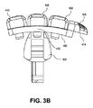
図3A、3Bはそれぞれ、本発明のある実施形態のひげ剃り組立体の、撓んでいない向き及び凸向きでの概略側面図である。横部材402はブリッジ404に結合され、独立したカートリッジ440、450及び460を保持する。図中の双方向矢印は、横部材402が取付け点416の周りで撓み、凹向き又は凸向きのどちらかになる能力を示している。有限空間「d」は、隣接するカートリッジ組440、450、460の間に存在する。有限空間「d」は、横部材402が撓んでひげ剃り組立体の面を凹ませることができる量を決定する。横部材402が凹向きに撓むにつれ、隣接するカートリッジは接触するようになり、更なる陥凹を防ぐ。有限空間「d」がない場合、(いったん組み立てられた)横部材402は面を凸状にさせる方向にしか撓むことしかできなくなる。凸向きは、使用者の鼻の下等の狭い領域のひげを剃るのに役立つ。一方、凹向きは、顎等の角のある部分の周りでひげを剃るのに役立つ。一般的に言えば、凹向きの可撓性よりも凸向きの可撓性の方が必要とされる。図示した実施形態では、先行プラットホーム414は弾性材料から形成してよくかつ刃よりも先に体毛を先行カートリッジ460から持ち上げるように設計された、一連のマイクロリブを支持する。先行プラットホーム414上の潤滑ストリップによってマイクロリブを全体的に又は部分的に置換できることを理解されたい。
3A and 3B are schematic side views, respectively, in an unbent and convex orientation of a shaving assembly of an embodiment of the present invention.
図3Bは、凸向きに撓み、取付け点416において引っ張られる横部材402を示す。上述のように、この向きにより、使用者の鼻の周り等の狭い空間の中に入りやすくなる。特に、先行プラットホーム414は、使用者がひげ剃り領域に対して組立体を押し付けるにつれてこの撓みを助長する力を提供し、先行プラットホーム414は取付け点416の周りで屈曲を開始するためのレバーアームとなる。
FIG. 3B shows the
図4Aは、ひげ剃りカートリッジのある実施形態の斜視図を示す。ひげ剃りカートリッジ100は、刃102、カバー104及び基部部材106を含んでよい。いくつかの実施形態では、刃102はカミソリ刃であってよい。カバー104は刃102に固定できる。カバー104は更に基部部材106に取り付けられ、刃102をカートリッジ100内部の適所に保持してよい。カバー104は刃102の上に、ひげ剃り中にカバー104及び刃102の切縁112が使用者の皮膚に接触するように位置決めされる。本態様では、カバー104は切縁112に沿って窪み118を画定し、これによって切縁112の一部が使用者の皮膚に露呈される。カバー104は、刃102上で保護カバーとして働き得る。
FIG. 4A shows a perspective view of an embodiment of a shaving cartridge.
カバー104は刃102に隣接する溝114を画定する。一実施形態では、溝は概してV字形である。溝は、第1のパネル108及び第2のパネル110によって画定されてよい。カバー104は保護カバーとして働くことに加え、従来のカミソリ刃カートリッジよりもよく皮膚全体に切縁112の圧力を拡散し、かつ皮膚全体にわたる切縁112の滑動を改善して、かすり傷及び切傷を低減するように寸法を定めてよい。これらの利点は、少なくとも部分的に、使用者の皮膚に接触するカバー104及び切縁112の表面積を、従来のカミソリ刃カートリッジと比較して約60%減少させることによって達成される。少し言い方を変えると、ひげ剃り平面でカートリッジの周辺に境界ボックスを描くとすると、溝の上方の面積は境界ボックス内部の面積の60%を表す。
Cover 104 defines a
そこに取り付けられた刃102を有するカバー104は、ひげ剃り動作中に、第2のパネル110の上端縁116及び切縁112が切断平面122を画定するように、基部部材106上に位置決めされる。溝領域114内部のカバー104の部分は、ひげ剃り中切断平面122の上方に持ち上げられたままとなるため、使用者の皮膚に接触しない。更に上端縁116は、ひげ剃りが更に近接できるように皮膚を引き伸ばす。
A
カバー104は、ひげ剃り中に使用者の皮膚に接触するのに適したいずれの材料から作製してもよい。カバー104は典型的には、例えばアルミニウム等の金属材料から作製してよい。また更なる実施形態では、カバー104はプラスチック材料等の他の材料から作製してもよい。いくつかの実施形態では、カバー104は、単一ユニットとしてアルミニウム板から打ち抜いてよい。他の実施形態では、カバー104は、射出成形、機械加工、又はカバー104の所望の特徴を生成するために適した他のいずれの製造プロセス等、当該技術分野で公知のいずれのプロセスによって形成してよい。
The
カバー104が金属材料から作製される実施形態では、使用者の皮膚全体にわたるカートリッジ100の移動を容易にするために、カバー104に潤滑コーティングを塗布してよい。典型的には、静電スプレー塗装法を用いて、カバー104の上端縁116に沿って、例えばテトラフルオロエチレン短鎖重合体の水性分散液等、水、アルコール、フレオン、又は多様なフッ化炭素液体の中の分散として、短鎖重合体等の固体を塗布してよい。別法として、例えばアロエベラ及び/又はココナツミルク等の潤滑材が注入された潤滑ストリップをカバー104に取り付けてよい。上述した潤滑コーティング及び/又は潤滑材のいずれを、基部部材106の、使用者の皮膚に接触する部分に更に配置してよい。
In embodiments where the
カバー104及び刃102の基部部材106への取り付けは、カバー104を刃102に直接溶接することによって達成できる。典型的には、カバー104は、刃102の長さ寸法に沿った様々な点で刃102に点溶接されてよい。次に、図7を参照してより詳しく説明するように、カバー104を基部部材106に取り付けてよい。刃102を基部部材106に直接取り付けるのとは対照的に、本明細書に開示するように、カバー104を用いて刃102を基部部材106に取り付けると、刃102の形状を維持できる、より剛性のカートリッジ100が得られる。この結果、より優れた滑動能力を有し、より長持ちする刃が得られると考えられる。
Attachment of the
基部部材106は、図7を参照してより詳しく説明するように、基部部材106のブリッジへの取付けを容易にするための架装ペグ120を含んでよい。一実施形態では、基部部材106は基部部材106から伸長する架装ペグ120と一体で形成される。基部部材106は、剃られた体毛が刃102の動きを妨げる又は遮ることなく通過し得る細長い開口124を更に含んでよい。
図4Bは、図4Aのひげ剃りカートリッジの線A、A’に沿った断面図を示す。図4Bは、切縁112が皮膚から延びる体毛128を剃るために皮膚126に沿って位置決めされるように回転された、図4Aのひげ剃りカートリッジ100を示す。この図から、第2のパネル110の上端縁116及び切縁112によって切断平面122が画定されることが分かる。皮膚126から伸びる体毛128を剃る間、カバー104の上端縁116及び切縁112だけが皮膚に沿って滑動するように、カバー104の溝114を皮膚126の上方に持ち上げる。いくつかの実施形態では、溝114は、ひげ剃り中に使用される石鹸、泡、水等の潤滑用流体及び/又は保湿用流体を皮膚126に対して保持する補助として機能し得る。このような特徴は、皮膚126に対するカートリッジ100の滑動及び一般にひげ剃り後の皮膚126の状態を更に改善し得る。
FIG. 4B shows a cross-sectional view of the shaving cartridge of FIG. 4A along line A, A '. FIG. 4B shows the shaving
図5は、図4Aに示したカバー及び刃の斜視図を示す。上述のように、カバー104は第1のパネル108及び第2のパネル110を含んでよい。窪み118を第1のパネル108の内部に形成し、取り付けられた刃102の切縁112の一部を露出させてよい。この図から、端縁116及び切縁112によって形成される切断平面122に対する溝領域114の深さをより明確に見ることができる。特に、第2のパネル110の端縁116及び切縁112だけが切断平面122の内部にあることが分かる。結果として、ひげ剃り中、端縁116及び切縁112だけが使用者の皮膚に接触する。一方、カバー104の溝領域114は皮膚の表面の上方に持ち上げられたままである。
FIG. 5 shows a perspective view of the cover and blade shown in FIG. 4A. As described above, the
カバー104は更に、第1のパネル108から伸長する停止部材1202、1204を含んでよい。停止部材1202、1204は、切縁112の周りに延在するよう寸法決めされる。本態様では、停止部材1202、1204は、刃102及び特に切縁112をカバー104の内部に適切に配置するための補助として機能する。停止部材1202、1204はカバー104と一体で形成してよい。
Cover 104 may further include
更に、カバー104は、基部部材106にカバー104を固定するためのタブ1206、1208、1210、1212を含んでよい。タブ1206、1208、1210、1212は、カバー104の下方に延在してよく、これによってそれらを下にある基部部材106に固定できる。図5は、基部部材106にタブ1206、1208を固定するための実質的にまっすぐな平坦な構造としてタブ1206、1208を示しているが、図6、7を参照してより詳しく説明するように、タブ1206、1208は屈曲していてもよい。タブ1202、1212を、タブ1206と1208との間に配置してよい。タブ1210、1212は、それぞれの端部にかかりが付いた部分1214、1216を含む、実質的にまっすぐな構造であってよい。カバー104を基部部材106の内部に配置する際、かかりが付いた部分1214、1216は基部部材106の部分に引っ掛かり、基部部材106にカバー104を固定する。
Further, the
図6は、図5に示すカバー及び刃の底面斜視図を示す。この図から、カバー104が第2のパネル110から伸長するバックプレート1302を更に含むことが分かる。バックプレート1302は刃102の下方に、及び基部部材106の裏面に沿って延在する(図7を参照)。本態様では、バックプレート1302は、刃102及びカバー104を基部部材106と位置合わせするための補助として機能する。タブ1206、1208、1210、1212は、バックプレート1302と一体で形成してよい。図6では、タブ1208、1206を、基部部材106にカバー104を固定するために使用される屈曲した構成で示す。
6 shows a bottom perspective view of the cover and blade shown in FIG. From this view, it can be seen that the
図7は、図4Aに示すひげ剃りカートリッジの背面斜視図を示す。この図から、カバー104がどのようにして基部部材106に取り付けられるのかが分かる。特に、カバー104を基部部材106に取り付けるために、カバー104のバックプレート1302は基部部材106の裏面に沿って配置される。次にタブ1206、1208を、基部部材106の下側の周りで屈曲させる。タブ1210、1212は、基部部材106の下側に沿ってブラケット1406によって形成される長穴1402、1404に差し込まれる。タブ1210、1212のかかり1214、1216はそれぞれ、長穴1402、1404の端縁に引っ掛かり、タブ1210、1212を適所に保持する。
FIG. 7 shows a rear perspective view of the shaving cartridge shown in FIG. 4A. From this figure, it can be seen how the
基部部材106は、ペグ120、1408を含む。図8を参照してより詳しく説明するように、ペグ120、1408を使用して、基部部材106をブリッジに固定できる。
図8は、ひげ剃り組立体の一実施形態の分解図を示す。ひげ剃り組立体500は、複数のカートリッジ100、502、504を含んでよい。カートリッジ100は、図4Aを参照して説明したカートリッジ100と実質的に同じであってよい。カートリッジ502、504は、カートリッジ100と実質的に同じであってよい。図8では、カートリッジ100は分解した状態で示されている。
FIG. 8 shows an exploded view of one embodiment of a shaving assembly. The shaving
各カートリッジは、カートリッジ100内部に刃102を共に保持するカバー104及び基部部材106を含む。一実施形態では、基部部材106は、基部部材から伸長する架装ペグ120及び480と一体で形成される。架装ペグ120、408はブリッジ508の穴506に係合し、その中で熱溶接、又は接着されてよい。多様な実施形態では、ブリッジ508は市販されている弾性ナイロン12、ポリウレタン、又は適切な弾性を有する他のいずれの合成材料から形成してよい。なお、各カートリッジの基部部材106は、1つの部品として互いに一体で形成できる。図9A、9Bを参照してより詳しく説明するように、ブリッジ508は、カミソリハンドルにカートリッジ100、502、504を取り付けるためにハンドル相互接続部材に取り付けてよい。
Each cartridge includes a
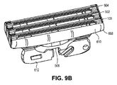
図9A、9Bはそれぞれ、図8のひげ剃り組立体の背面斜視図及び正面斜視図を示す。図8を参照して上述したカートリッジ等の複数の独立したカートリッジ100、502、504がブリッジ508に連結される。
9A and 9B show a rear perspective view and a front perspective view, respectively, of the shaving assembly of FIG. A plurality of
図示した実施形態では、3つの独立したカートリッジ、つまり先行カートリッジ100、中央カートリッジ502及び後続カートリッジ504を使用する。一実施形態では、各カートリッジは独立してブリッジ508に取り付けられる。中央カートリッジ502は実質的に取付け点602に取り付けてよく、先行カートリッジ100及び後続カートリッジ504は中央カートリッジに隣接するいずれかの側に取り付けてよい。
In the illustrated embodiment, three independent cartridges are used: a leading
いくつかの実施形態では、ブリッジ508は可撓性であってよく、凹向きと凸向きとの間で撓むことができる。本実施形態では、ブリッジ508の横材604、608は、市販されている弾性ナイロン12、ポリウレタン、又は適切な弾性を有する他のいずれの合成材料から形成されてよい。例えば力が印加されていない場合等の静止時、架装組立体508の横材604、606は実質的に平坦である。カートリッジ100、502、504は、例えばリベット614を使用して横材604、606に取り付けてよい。また更なる実施形態では、カートリッジ100、502、504は、接着剤、熱溶接、又はその組合せ等の任意の他の従来の架装機構を使用して横材604、606に取り付けてよい。カートリッジ100、502、504はそれぞれ独立しているため、カミソリ面が凸状になるのに伴うあるカートリッジの相対的な移動は他のカートリッジによる影響を受けない。このような移動は、横材604、606の可撓性及び弾性のみによって制約される。このような実施形態では、例えばひげ剃りヘッドに力が印加されていない等、カミソリが静止状態である場合に、カートリッジの集合体の刃が平面を画定する。代替実施形態では、横材604、606は可撓性を有さず、これにより全てのカートリッジが実質的に剛性のひげ剃り平面に保持されてよい。
In some embodiments, the
上述のように、組立体がひげ剃り領域に沿って引っ張られるのに伴い、先行カートリッジ100は中央カートリッジ502より早くひげ剃り領域に達する。一実施形態では、ひげ剃り組立体は先行プラットホーム608を含んでよい。先行プラットホーム608は、横材604、606に取り付けてよく、又は横材604、606と共に形成してよい。潤滑ストリップ610は、先行カートリッジ100より前に潤滑剤を放出するよう位置決めされる。
As described above, as the assembly is pulled along the shave area, the
いくつかの実施形態では、潤滑ストリップ610(図9Bを参照)を先行プラットホーム608に適用してよい。更に又は代替として、各カートリッジ100、502、504は、上述のように、後続のカートリッジが到着する前にひげ剃り領域を滑りやすくする、固有の潤滑剤を有してもよい。代替実施形態では潤滑ストリップ610の代わりに、先行カートリッジ100の前に体毛を持ち上げる可撓性リブを設けてよい。
In some embodiments, a lubricating strip 610 (see FIG. 9B) may be applied to the leading
ハンドル相互接続612を組立体508に連結して、ひげ剃り組立体をカミソリハンドルに連結できるようにしてよい。カミソリ相互接続612は、市販されている又は後に設計される可能な様々なカミソリハンドルに接続できるようにするために必要ないずれの構成を有してもよい。
図10は、本発明の一実施形態のカミソリヘッドの平面分解図を示す。カミソリヘッド800は、その一部を形成する複数のカミソリカートリッジ810を有する。カミソリカートリッジ810は、刃802、基部804、及びカバー806を含み、上記図4A〜9を参照して説明したように製造されてよい。図示した実施形態では、3つのカートリッジ810をヨーク820に連結する。ヨーク820は、材料の単一の一体部品として成形される。一実施形態では、ヨークは熱可塑性物質から成形される。一実施形態では、選択された材料はEMS−GRIVORY製のEMS Grillflex ELG 5660である。ただし、他の熱可塑性物質を使用してもよい。
FIG. 10 shows a plan exploded view of a razor head according to an embodiment of the present invention. The
ヨーク820は、カートリッジ810を受け入れるために取付け点830を定める1組の横材824と一体で形成されるブリッジ822を含む。ブリッジ822は、1組の一体丁番832によって横材824に連結される。一体丁番は、刃組立体が一体丁番を中心として、第1の弧及び第2の弧を通って順方向及び逆方向に枢動できるようにする厚さtを有する。一実施形態では、tは1mm±0.1に等しい。他の実施形態は、より大きい又はより小さいtを有してよい。枢動の弧は、厚さt及び一体丁番832を形成する材料の剛性によって制限される。成形に適切な材料を選択することで、一体丁番における早期疲労が回避される。一実施形態では、取付け点830は横材824を通して画定される一連の穿孔である。横材は、上記他の実施形態で説明したものと同様の可撓性特性を有してよい。これによって、基部804の架装ペグ(図10では図示せず)を穿孔830内部に熱溶接できる。一実施形態では、各カートリッジ810は、横材824の間にかかる39.6ミリメートルの長さ寸法を有する。他の寸法は、本発明の他の実施形態の範囲内として意図される。
The
いくつかの実施形態では、ヨーク820は先行プラットホーム826を含み、この先行プラットホーム826は潤滑剤を受け取るためのウェル828を画定できる。このようにして、組立体内部において先行カートリッジの先行する刃の前に潤滑剤を皮膚に塗布する。本発明の一実施形態では、従来のスティックハンドル又は他のいずれの適切なハンドル等のハンドルを刃組立体に取り付けることを可能にするハンドル取付け部品834もまた、ヨーク820の一部として成形される。特に、いくつかの実施形態では、カートリッジ810は図4A〜9を参照して説明した通りであるが、他の実施形態では、図1A〜3Bを参照して説明したカートリッジを、一体ヨーク820に取り付けてよい。別の実施形態では、カートリッジ810の基部804はヨーク820と一体で成形される。
In some embodiments, the
製造の観点から、図10を参照して説明する実施形態は、丁度4つの固有の部品を含む(これらの部品のうち3つを3回複製して、3カートリッジ刃組立体の合計部品点数を10とする)。この部品点数は、現在の業界大手Gillete(登録商標)及びSchick(登録商標)の製品に関連する部品点数の半分未満である。例として、Schick Hydro(登録商標)は25の別個の部品を含み、Gillete Fusion(登録商標)は24の別個の部品を含む。基部804がヨーク820と一体で成形される実施形態では、部品点数は基部の数分減少される。更に、基部取付けの製造ステップが回避される。
From a manufacturing point of view, the embodiment described with reference to FIG. 10 includes exactly four unique parts (three of these parts are duplicated three times to give a total part count for the three cartridge blade assembly. 10). This number of parts is less than half the number of parts associated with products of the current industry leaders Gillete (R) and Stick (R). As an example, Stick Hydro (R) includes 25 separate parts, and Gillet Fusion (R) includes 24 separate parts. In an embodiment where the
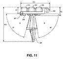
図11は、本発明の一実施形態のひげ剃りヘッドの側面図である。一実施形態の特定の寸法をミリメートル単位で示す。一実施形態では、一体丁番832により、横材824及び横材に連結されたカートリッジが、一実施形態では80°である弧fを通って前方に枢動できる。比較のために、Gillete Fusion(登録商標)は単一方向で55°の最大枢動弧を有する。同じ一体丁番により、カートリッジ810及び横材824は、例えば75°の弧qを通って後方に枢動できるようにする。他の実施形態では、fは60°又は50°であってよく、qは例えば50°又は40°となるように選択してよい。前方弧及び後方弧は静止位置から定義され、静止位置は、作動力が印加される際のヘッドの位置である。しかしながら、枢動弧が大きいほど、刃802が効果的な位置で使用者の皮膚に留まるハンドルの角度の範囲が大きくなる。一実施形態では、横材824も可撓性であり、従ってカミソリの全体的な面は、図3A〜3Bを参照して上述したように、凹状又は凸状となるように撓んでよい。代替実施形態では、全てのカートリッジをひげ剃り平面に保持しつつヘッドが一体丁番を中心に枢動できるよう、横材824は可撓性を有さなくてよい。
FIG. 11 is a side view of a shaving head according to an embodiment of the present invention. Certain dimensions of one embodiment are shown in millimeters. In one embodiment, the
図12A〜12Cは、一体ヨークを伴う単一カートリッジを有する本発明の代替実施形態の図である。ひげ剃りヘッド900は、横材924に連結されたブリッジ922を有するヨーク920を含む。横材924は、単一カートリッジ810の取付け点を定める。例えば、横材924は一体で成形される架装ペグ838を受け入れるための穿孔を画定してよく、連結は熱溶接、接着又は他のいずれの適切な方法によってよい。ヨーク920は、組立体をひげ剃りカミソリハンドルに結合できるようにするために、ハンドル架装部品934を含んでよい。図示した実施形態では、カートリッジの長さは39.6ミリメートルである。ただし、例えば19.8ミリメートルである縮小サイズのカートリッジは本発明の範囲及び意図の範囲内である。他のサイズも本発明の範囲及び意図の範囲内である。
12A-12C are views of an alternative embodiment of the present invention having a single cartridge with an integral yoke. The shaving
図12Bは、本発明の単一カートリッジ実施形態の側面図を示す。この図から、カートリッジの一実施形態の断面寸法が3.81ミリメートルであることが分かる。図12Cは、単一カートリッジ実施形態の平面図を示す。この図では、カバー刃組立体の寸法が3.2ミリメートルであることが分かる。このような小さい寸法によって、カミソリは鼻の周り等の狭い空間でも効果的に機能できる。 FIG. 12B shows a side view of a single cartridge embodiment of the present invention. From this figure, it can be seen that the cross-sectional dimension of one embodiment of the cartridge is 3.81 millimeters. FIG. 12C shows a top view of a single cartridge embodiment. In this view, it can be seen that the dimensions of the cover blade assembly are 3.2 millimeters. With such small dimensions, the razor can function effectively even in a narrow space such as around the nose.
多様な実施形態に関連して明示的な寸法を示し、説明しているが、これらの寸法を変更することは範囲及び意図の範囲内である。従って、実際の寸法は詳説した寸法よりも大きい場合もあれば、小さい場合もある。ただし、図示した寸法は、非常に優れたひげ剃りを実現する高品質の製品を生み出すことが判明している。 While explicit dimensions have been shown and described in connection with various embodiments, it is within the scope and intent of changing these dimensions. Thus, the actual dimensions may be larger or smaller than the detailed dimensions. However, the dimensions shown have been found to produce a high quality product that achieves a very good shave.
上述の明細書では、本発明の実施形態をその特定の実施形態に関して説明した。ただし、添付の特許請求の範囲に記載される本発明のより幅広い精神及び範囲から逸脱することなく、本発明に多様な修正及び変更を加えることができることは明らかであろう。従って、明細書及び図面は限定的な意味ではなく例示的な意味に解釈されるべきである。 In the foregoing specification, embodiments of the invention have been described with reference to specific embodiments thereof. However, it will be apparent that various modifications and changes may be made thereto without departing from the broader spirit and scope of the invention as set forth in the appended claims. The specification and drawings are, accordingly, to be regarded in an illustrative sense rather than a restrictive sense.
Claims (17)
前記ヨークに連結され前記横材の間にかかる、カミソリ刃を有するカートリッジを備え、前記刃の長さ方向は前記横材に対して垂直であり、
少なくとも第2のカートリッジは、少なくとも1つの刃を有し、かつ前記横材の間にかかる前記ヨークに連結し、前記カートリッジは集団的に刃の組立体を形成し、
前記一体丁番は、前記刃の組立体が側面視において前記一体丁番を中心に最大枢動角が90°ないし155°で枢動できるようにする厚さを有していることを特徴とする
ひげ剃り用カミソリ。 A yoke formed as a single piece, including a bridge and a set of cross members each connected to the bridge with a living hinge; and a razor blade connected to the yoke and between the cross members A longitudinal direction of the blade is perpendicular to the cross member,
At least a second cartridge having at least one blade and coupled to the yoke between the cross members, the cartridge collectively forming an assembly of blades;
The integral hinge has a thickness that allows the blade assembly to pivot at a maximum pivot angle of 90 ° to 155 ° around the integral hinge in a side view. A razor for shaving.
前記前方向及び後方向は、静止位置に対して定義される、請求項1に記載のひげ剃り用カミソリ。 The integral hinge allows for forward pivoting through a first arc greater than 50 ° and backward pivoting through a second arc greater than 50 °;
The shaving razor according to claim 1, wherein the forward direction and the backward direction are defined with respect to a rest position.
基部;並びに
前記刃の表面に沿った長さの刃及び前記基部に連結されたカバーを備え、前記カバーは刃の切縁の後ろにある溝を画定することを特徴とする請求項1に記載のひげ剃り用カミソリ。 The cartridge is:
2. A base; and a length of blade along the surface of the blade and a cover coupled to the base, the cover defining a groove behind a cutting edge of the blade. Razor for shaving.
を備える、請求項7に記載のひげ剃り用カミソリ。 Defining the groove along the length of the cover, the groove open to a shaving plane for reducing the surface area of the cover that contacts the user's skin during shaving; The shaving razor according to claim 7 provided.
前記第1の側部は前記刃に隣接し、前記刃に対してほぼ平行であり、
前記第2の側部は前記刃に対して急な角度を有し、第2の縁部を有し、
前記第2の縁部及び前記切縁は、ひげ剃り平面を画定する、請求項7に記載のカミソリ。 The groove is defined in a generally V shape having a first side and a second side;
The first side is adjacent to the blade and substantially parallel to the blade;
The second side has a steep angle with respect to the blade and has a second edge;
The razor according to claim 7, wherein the second edge and the cutting edge define a shaving plane.
前記基部部材に取り付けられた少なくとも1つのタブ部分を更に備える、請求項7に記載の装置。 The apparatus of claim 7, further comprising: a support member formed integrally with the cover and having a rear portion extending from the cover to the base member; and at least one tab portion attached to the base member.
切縁を有する前記カミソリ刃であって、複数の前記刃の前記切縁が静止状態において平面を画定するように各基部内に連結された、前記カミソリ刃を備え;
カバーは各前記刃に位置決めされ、それぞれの前記基部に連結され、前記カバーはカバーの長さ方向に沿って溝を画定し、ひげ剃り平面に空いた前記溝は、ひげ剃り中にユーザの皮膚と接触する前記カバーの表面積を低減するためのものであることを特徴とする、請求項1に記載のひげ剃り用カミソリ。 A plurality of bases coupled to the bridge, each set of bases defining a space therebetween; and the razor blade having a cutting edge, wherein the cutting edges of the plurality of blades are stationary Said razor blades connected within each base to define a plane in condition;
A cover is positioned on each of the blades and connected to the respective base, the cover defining a groove along the length of the cover, and the groove vacated in the shaving plane 2. The shaving razor according to claim 1, wherein the shaving razor is for reducing the surface area of the cover in contact with the shaving.
Applications Claiming Priority (3)
| Application Number | Priority Date | Filing Date | Title |
|---|---|---|---|
| US13/173,911 US9144914B2 (en) | 2011-06-30 | 2011-06-30 | Razor cartridge with reduced part count and expanded range of motion |
| US13/173,911 | 2011-06-30 | ||
| PCT/US2012/044436 WO2013003484A2 (en) | 2011-06-30 | 2012-06-27 | Razor cartridge with reduced part count and expanded range of motion |
Publications (3)
| Publication Number | Publication Date |
|---|---|
| JP2014518136A JP2014518136A (en) | 2014-07-28 |
| JP2014518136A5 JP2014518136A5 (en) | 2015-09-03 |
| JP6247208B2 true JP6247208B2 (en) | 2017-12-13 |
Family
ID=47389140
Family Applications (1)
| Application Number | Title | Priority Date | Filing Date |
|---|---|---|---|
| JP2014518970A Active JP6247208B2 (en) | 2011-06-30 | 2012-06-27 | Razor cartridge with reduced parts count and expanded range of motion |
Country Status (8)
| Country | Link |
|---|---|
| US (3) | US9144914B2 (en) |
| EP (1) | EP2726259B1 (en) |
| JP (1) | JP6247208B2 (en) |
| KR (1) | KR101945906B1 (en) |
| CN (1) | CN103764354B (en) |
| HK (1) | HK1197210A1 (en) |
| IL (1) | IL230037B (en) |
| WO (1) | WO2013003484A2 (en) |
Families Citing this family (39)
| Publication number | Priority date | Publication date | Assignee | Title |
|---|---|---|---|---|
| GB2462086A (en) * | 2008-07-22 | 2010-01-27 | Alon Coresh | Articulated Shaving Set |
| US8533959B2 (en) * | 2010-10-11 | 2013-09-17 | The Gillette Company | Cartridges and razors with trimming wing |
| US9144914B2 (en) | 2011-06-30 | 2015-09-29 | Rolling Razor, Inc. | Razor cartridge with reduced part count and expanded range of motion |
| US9156175B2 (en) * | 2011-12-09 | 2015-10-13 | The Gillette Company | Fluid applicator for a personal-care appliance |
| USD707885S1 (en) | 2013-02-28 | 2014-06-24 | The Gillette Company | Shaving razor cartridge |
| US9457486B2 (en) | 2013-03-13 | 2016-10-04 | Rolling Razor, Inc | Shaving cartridge with individual blade guards |
| WO2014209776A1 (en) * | 2013-06-27 | 2014-12-31 | Shavelogic, Inc. | Shaving system |
| EP3083163B1 (en) * | 2013-12-18 | 2020-02-05 | BIC-Violex S.A. | A shaving blade cartridge |
| KR101590595B1 (en) * | 2014-01-15 | 2016-02-01 | 주식회사 하이원화이어 | Ceramic razor blade and ceramic razor blade assembly having the same |
| US10131062B1 (en) | 2014-01-31 | 2018-11-20 | Dryfhout Enterprises, Llc | Body shaver with comb and blade |
| US10500744B1 (en) | 2014-01-31 | 2019-12-10 | Dryfhout Properties, Llc | Safety razor with plurality of comb and integrated blade groups |
| US10315322B1 (en) | 2016-05-17 | 2019-06-11 | Dryfhout Properties, Llc | Method of using a back shaver handle |
| US11077570B2 (en) | 2014-01-31 | 2021-08-03 | Dryfhout Properties, Llc | Flexible back shaver |
| US9616584B2 (en) | 2014-03-20 | 2017-04-11 | Rolling Razor, Inc. | Shaving razor and shaving handle with an interconnection mechanism |
| US9630332B2 (en) * | 2014-09-29 | 2017-04-25 | Alon Leon Coresh | Shaving razor with one or more reciprocating blades |
| US20160158949A1 (en) * | 2014-12-08 | 2016-06-09 | The Gillette Company | Razor Cartridge Guard Structure |
| US20160158948A1 (en) * | 2014-12-08 | 2016-06-09 | The Gillette Company | Razor Cartridge Guard Structure |
| EP3685974B1 (en) | 2015-12-01 | 2022-08-10 | BIC Violex Single Member S.A. | Shaving razors and shaving cartridges |
| MX2018011289A (en) | 2016-03-18 | 2019-02-18 | Personal Care Marketing And Res Inc | Razor cartridge. |
| US9937629B1 (en) | 2016-05-17 | 2018-04-10 | Dryfhout Enterprises, Llc | Two-point discrimination safety razor assembly |
| US10493643B1 (en) | 2016-05-17 | 2019-12-03 | Dryfhout Properties, Llc | Leveled back shaver |
| US10543609B2 (en) | 2016-05-17 | 2020-01-28 | Dryfhout Properties, Llc | Elevated shaver |
| USD877983S1 (en) | 2016-09-09 | 2020-03-10 | The Gillette Company Llc | Shaving razor cartridge |
| EP3292965B1 (en) | 2016-09-09 | 2021-05-26 | The Gillette Company LLC | Shaving razor cartridge and method of assembling |
| US9993931B1 (en) | 2016-11-23 | 2018-06-12 | Personal Care Marketing And Research, Inc. | Razor docking and pivot |
| US11117278B2 (en) * | 2017-06-06 | 2021-09-14 | The Gillette Company Llc | Shaving razor cartridge |
| KR101876233B1 (en) * | 2017-09-29 | 2018-07-10 | 주식회사 도루코 | Razor cartridge assembly |
| US11541560B2 (en) * | 2018-03-01 | 2023-01-03 | Rolling Razor, Inc. | Precision razor with low cost assembly |
| US10500746B2 (en) | 2018-05-07 | 2019-12-10 | Leon Coresh | Reciprocating razor with living hinge interconnections |
| USD884971S1 (en) | 2019-02-27 | 2020-05-19 | Pcmr International Ltd | Razor cartridge |
| USD884969S1 (en) | 2019-02-27 | 2020-05-19 | Pcmr International Ltd | Combined razor cartridge guard and docking |
| USD884970S1 (en) | 2019-02-27 | 2020-05-19 | PCMR International Ltd. | Razor cartridge guard |
| US11351689B2 (en) * | 2019-03-14 | 2022-06-07 | Neckrazor LLC | Razor device |
| USD921984S1 (en) | 2019-03-19 | 2021-06-08 | The Gillette Company Llc | Shaving razor cartridge |
| US11104017B2 (en) * | 2019-05-31 | 2021-08-31 | Conair Corporation | Hair cutter blade gap adjustment system |
| JP6600762B1 (en) * | 2019-07-31 | 2019-10-30 | 株式会社貝印刃物開発センター | Razor head |
| US11167437B2 (en) | 2019-12-02 | 2021-11-09 | Leon Coresh | Reciprocating razor assembly with different amplitudes of motion |
| EP3858565A1 (en) * | 2020-01-30 | 2021-08-04 | BIC Violex S.A. | Modular frame for shaving head |
| US11000960B1 (en) | 2020-11-16 | 2021-05-11 | Personal Care Marketing And Research, Inc. | Razor exposure |
Family Cites Families (110)
| Publication number | Priority date | Publication date | Assignee | Title |
|---|---|---|---|---|
| US3092904A (en) * | 1960-05-09 | 1963-06-11 | Bruecker John | Movable cutter for a dry shaver having saw tooth design cutting edge |
| US3138865A (en) * | 1960-08-13 | 1964-06-30 | Meyer Eugen | Safety razor having skin-stretching and guiding means |
| US3137940A (en) * | 1960-12-30 | 1964-06-23 | Curci Alfred | Disposable combination safety-razor and blade magazine |
| US3412464A (en) * | 1967-01-16 | 1968-11-26 | Karl M. Keck | Razor having a rotative blade holder |
| GB1460732A (en) * | 1973-03-01 | 1977-01-06 | Gillette Co | Safety razor |
| US4094063A (en) * | 1976-12-15 | 1978-06-13 | The Gillette Company | Razor assembly with pivotally mounted cartridge |
| US4170821A (en) | 1977-12-02 | 1979-10-16 | Warner-Lambert Company | Razor cartridges |
| GB2030909A (en) * | 1978-08-15 | 1980-04-16 | Wilkinson Sword Ltd | Razors |
| EP0020816A1 (en) | 1979-06-19 | 1981-01-07 | The Gillette Company | Shaving razor assembly |
| US4392303A (en) * | 1979-12-31 | 1983-07-12 | Warner-Lambert Company | One-piece razor handle |
| US4461078A (en) * | 1982-02-01 | 1984-07-24 | Carreker Reginald V | Styling razor |
| US4459744A (en) * | 1982-02-04 | 1984-07-17 | Alan K. Roberts | Razor blade apparatus and method |
| US4534110A (en) * | 1982-12-28 | 1985-08-13 | David Mall | Triple-edge safety razor and blade |
| US4501066A (en) * | 1983-04-11 | 1985-02-26 | Sceberras Conrad T | Dual headed razor system |
| US4516320A (en) | 1983-04-28 | 1985-05-14 | Warner-Lambert Company | Dynamic razor |
| US4641429A (en) * | 1984-12-24 | 1987-02-10 | Abatemarco Michael R | Razor blade cartridge unit with dual blades |
| US4720917A (en) * | 1985-09-13 | 1988-01-26 | Solow Terry S | Flexible blade contour razor |
| US4932122A (en) | 1987-12-21 | 1990-06-12 | The Gillette Company | Safety razor blade assembly |
| US4993153A (en) * | 1989-10-27 | 1991-02-19 | Henry James G | Multiple blade stand up razor |
| AR244587A1 (en) * | 1989-11-17 | 1993-11-30 | Warner Lambert Co | Pivoting safety razor assembly |
| US4989328A (en) * | 1990-03-16 | 1991-02-05 | Daniel Sokoloff | Dual headed razor assembly |
| US5152064A (en) | 1991-09-09 | 1992-10-06 | Johnston William M | Shaving method and apparatus |
| GB9208098D0 (en) | 1992-04-13 | 1992-05-27 | Gillette Co | Razor with movable cartridge |
| US5206994A (en) | 1992-06-04 | 1993-05-04 | Catherine Lin | Collapsible razor |
| USD343922S (en) * | 1992-10-13 | 1994-02-01 | Ahlgren Erick L | Disposable razor |
| US5307564A (en) * | 1992-12-01 | 1994-05-03 | Schoenberg Frederic D | Safety razor |
| US6082007A (en) * | 1993-02-22 | 2000-07-04 | Andrews; Edward A. | In-line bi-directional manual shaving razors |
| US5343622A (en) * | 1993-02-22 | 1994-09-06 | Andrews Edward A | Bi-directional razor device |
| US6434828B1 (en) | 1993-02-22 | 2002-08-20 | Edward A. Andrews | In-line razor device with twin pivoting heads |
| US6161288A (en) | 1993-02-22 | 2000-12-19 | Andrews; Edward A. | Four blade bi-directional razor structure with flexible guard system |
| US6141875A (en) * | 1993-02-22 | 2000-11-07 | Andrews; Edward A. | In-line shaving razors with twin pivoting heads |
| WO1995004637A1 (en) | 1993-08-04 | 1995-02-16 | Warner-Lambert Company | Dynamic shaving system |
| US6212777B1 (en) | 1993-09-29 | 2001-04-10 | The Gillette Company | Safety razors |
| US5426853A (en) | 1994-03-09 | 1995-06-27 | Mcninch; Herbie | Method of shaving and improved shaver |
| US5546660A (en) * | 1994-09-30 | 1996-08-20 | Warner-Lambert Company | Dynamic razor head |
| US5450671A (en) * | 1994-10-21 | 1995-09-19 | Harshman; David | Hair trimming device |
| IL116684A (en) | 1996-01-05 | 1998-12-06 | Mepro Epilady Ltd | Shaving device |
| GB9600818D0 (en) | 1996-01-16 | 1996-03-20 | Gillette Co | Safety razors |
| US5953825A (en) * | 1996-01-16 | 1999-09-21 | The Gillette Company | Safety razors |
| AU2129597A (en) | 1996-03-27 | 1997-10-17 | Warner-Lambert Company | Shaving system with uniform shaving forces |
| US5711076A (en) | 1996-03-27 | 1998-01-27 | The Gillette Company | Shaving system with improved guard structure |
| US5781997A (en) | 1997-01-17 | 1998-07-21 | Warner-Lambert Company | Ultra-flexible shaving cartridge |
| US6243951B1 (en) * | 1997-02-18 | 2001-06-12 | The Gillette Company | Safety razors |
| GB9715501D0 (en) * | 1997-07-22 | 1997-10-01 | Gillette Co | Safety razors |
| US6125857A (en) * | 1998-07-13 | 2000-10-03 | Silber; David | Dual sideburn trimmer |
| US6308416B1 (en) * | 1998-12-31 | 2001-10-30 | The Gillette Company | Surface conforming shaving razor and handle therefor |
| US6052905A (en) * | 1999-01-02 | 2000-04-25 | Branchinelli; Anthony | Dual sculptor retractable razor |
| DE29905882U1 (en) * | 1999-03-31 | 1999-07-08 | Setz | Disposable razor |
| US6138361A (en) | 1999-04-21 | 2000-10-31 | Warner-Lambert Company | Pivotable razor assembly and cartridge |
| US20020023352A1 (en) * | 2000-02-18 | 2002-02-28 | Samson Mil'shtein | Razor cartridge with enhanced access to wrinkled and curved skin surfaces |
| US6880253B1 (en) | 2000-06-23 | 2005-04-19 | Bic Violex S.A. | Razor with a movable shaving head |
| US6694626B2 (en) * | 2000-06-23 | 2004-02-24 | Rolling Razor Llc | Razor |
| US6493950B1 (en) * | 2000-06-23 | 2002-12-17 | Rolling Razor, L.L.C. | Rolling razor and shaving method |
| GB0025336D0 (en) | 2000-10-16 | 2000-11-29 | Gillette Co | Safety razors |
| US20040020053A1 (en) | 2000-10-16 | 2004-02-05 | The Gillette Company | Safety razors |
| CA2356571A1 (en) * | 2000-10-27 | 2002-04-27 | Vincent Cosmo Motta | Shaving systems with handle to razor head attachment mechanism and methods of performing same |
| US6550148B2 (en) * | 2001-08-15 | 2003-04-22 | Corbett W. Cecil | Shaving method and apparatus |
| FR2829716A1 (en) * | 2001-09-20 | 2003-03-21 | Josephine Ventimiglia | Pocket razor having replaceable head with four cutting edges has head on articulated support forming upper part of handle |
| US7210229B2 (en) | 2002-04-24 | 2007-05-01 | Eveready Battery Company, Inc. | Razor cartridge |
| US7137205B2 (en) | 2002-10-01 | 2006-11-21 | The Gillette Company | Linkage mechanism providing a virtual pivot axis for razor apparatus with pivotal head |
| US20040128835A1 (en) * | 2002-10-21 | 2004-07-08 | Eveready Battery Company, Inc. | Bidirectional shaving cartridge and razor including same |
| US7086160B2 (en) | 2002-10-21 | 2006-08-08 | Eveready Battery Company, Inc. | Bidirectional shaving implement |
| US7111401B2 (en) | 2003-02-04 | 2006-09-26 | Eveready Battery Company, Inc. | Razor head having skin controlling means |
| JP4334567B2 (en) | 2003-02-19 | 2009-09-30 | エバレデイ バツテリ カンパニー インコーポレーテツド | Wet shaving cartridge with shaving aid |
| AU2004213419B2 (en) * | 2003-02-19 | 2007-04-26 | Edgewell Personal Care Brands, Llc | Multiple blade razor cartridge |
| US20040177519A1 (en) * | 2003-03-14 | 2004-09-16 | Louis D. Tomassetti | Flexible razor and dispenser with pivoting head |
| US20040231161A1 (en) | 2003-03-26 | 2004-11-25 | Eveready Battery Company, Inc. | Wet shaving device with wire-wrapped blade sets |
| GB2406537B (en) | 2003-07-21 | 2006-09-06 | Gillette Co | Safety razors |
| GB2408010B (en) * | 2003-11-17 | 2007-03-28 | Knowledge & Merchandising Inc | Shaving product |
| JP3931881B2 (en) * | 2003-12-08 | 2007-06-20 | フェザー安全剃刀株式会社 | Razor with protective member |
| US20050188539A1 (en) | 2004-02-26 | 2005-09-01 | Prudden John Jr. | Shaving blade unit |
| US20050198825A1 (en) | 2004-03-11 | 2005-09-15 | Apprille Domenic V.Jr. | Dispensers for razor blade cartridges |
| EP1773549B1 (en) * | 2004-07-22 | 2008-11-05 | BIC Violex S.A. | Razor equipped with several pivotally mounted shaving heads |
| JP2008514280A (en) * | 2004-09-24 | 2008-05-08 | エバレディ バッテリー カンパニー インコーポレーテッド | Shaving equipment using discrete cartridge segments |
| GB2411141B (en) | 2004-10-14 | 2006-03-22 | Mark Richard Hesketh | Shaving device having multiple razor blades |
| US20060080837A1 (en) | 2004-10-20 | 2006-04-20 | Robert Johnson | Shaving razors and cartridges |
| US7681314B2 (en) * | 2005-06-10 | 2010-03-23 | Eveready Battery Company Inc. | Inter-blade guard and method for manufacturing same |
| US20070283567A1 (en) * | 2006-06-13 | 2007-12-13 | Magli Anthony J | Dual headed razor |
| GB0615113D0 (en) | 2006-07-28 | 2006-09-06 | Gillette Co | Wet razor with conforming blade support |
| JP4912074B2 (en) | 2006-08-11 | 2012-04-04 | 株式会社泉精器製作所 | Locking device |
| US20080196251A1 (en) * | 2007-02-15 | 2008-08-21 | The Gillette Company | Support structure for a flexible razor blade assembly |
| GB0716941D0 (en) * | 2007-08-31 | 2007-10-10 | Knowledge & Merchandising Inc | Razor handle |
| US8024863B2 (en) * | 2007-11-02 | 2011-09-27 | The Gillette Company | Conforming wet shaving razor |
| BRMU8801452U2 (en) * | 2008-05-08 | 2010-01-05 | Rodrigo Dos Santos Coelho | constructive arrangement applied in thimble for use in trichotomy |
| ES2370364T3 (en) * | 2008-05-23 | 2011-12-14 | Feintechnik Gmbh Eisfeld | UNIT OF SHAVING BLADES WITH MEMBRANE GOZNE. |
| JP5207853B2 (en) | 2008-07-02 | 2013-06-12 | パナソニック株式会社 | Still image and moving image imaging apparatus |
| GB2462086A (en) | 2008-07-22 | 2010-01-27 | Alon Coresh | Articulated Shaving Set |
| FR2935920B1 (en) * | 2008-09-16 | 2014-03-07 | Philippe Robert Gessat | MECHANICAL RAZOR IN V. |
| US20110016724A1 (en) * | 2009-07-24 | 2011-01-27 | Matthew Frank Murgida | Resilient Skin Contacting Members to Facilitate Pivoting |
| KR20110024234A (en) * | 2009-09-01 | 2011-03-09 | 주식회사 도루코 | Razor cartridge |
| US8707561B1 (en) * | 2010-05-31 | 2014-04-29 | Brian Eugene Kneier | Shaving device with a pad |
| US8448339B2 (en) | 2010-08-03 | 2013-05-28 | The Gillette Company | Shaving cartridge with supressed blade geometry |
| USD654222S1 (en) * | 2011-04-20 | 2012-02-14 | Rolling Razor, Inc. | Handle for a shaving razor |
| KR101082303B1 (en) * | 2011-05-24 | 2011-11-09 | 정은택 | Razor |
| US9144914B2 (en) | 2011-06-30 | 2015-09-29 | Rolling Razor, Inc. | Razor cartridge with reduced part count and expanded range of motion |
| US20130152400A1 (en) * | 2011-12-16 | 2013-06-20 | Joaquin Nunez | Personal shaving device having opposing sets of blades |
| US8671576B1 (en) * | 2012-03-27 | 2014-03-18 | Vernon P. Hotella | Divisible head razor device |
| US9289908B2 (en) * | 2012-09-10 | 2016-03-22 | Andrea Lee Marder | Multi-headed razor device |
| US9457486B2 (en) * | 2013-03-13 | 2016-10-04 | Rolling Razor, Inc | Shaving cartridge with individual blade guards |
| US9701033B2 (en) * | 2013-03-15 | 2017-07-11 | Prime 9 Shave, Inc. | Multi-headed safety razor |
| DE102013008942A1 (en) * | 2013-05-25 | 2014-12-18 | Hans-Georg Boehm | Wet shaver with two or more blade blocks |
| EP3010686A1 (en) * | 2013-06-17 | 2016-04-27 | The Gillette Company | A glide member comprising low to no hygroscopic components for use with a razor |
| US20140366361A1 (en) * | 2013-06-17 | 2014-12-18 | The Gillette Company | Article for carrying a glide member for use with a razor |
| US20140366380A1 (en) * | 2013-06-17 | 2014-12-18 | The Gillette Company | Article For Carrying A Glide Member For Use With A Razor |
| US9616584B2 (en) * | 2014-03-20 | 2017-04-11 | Rolling Razor, Inc. | Shaving razor and shaving handle with an interconnection mechanism |
| US9630332B2 (en) * | 2014-09-29 | 2017-04-25 | Alon Leon Coresh | Shaving razor with one or more reciprocating blades |
| US20160193740A1 (en) * | 2014-12-05 | 2016-07-07 | James Joseph Phillips | Sure Grip Dual Head Shaving Razor |
| US20150183119A1 (en) * | 2015-03-04 | 2015-07-02 | Walter Contaldi | Double Sided Razor and Method of Use |
| US10086522B2 (en) * | 2015-03-04 | 2018-10-02 | Walter Contaldi | Double sided razor and method of use |
| WO2016192743A1 (en) * | 2015-06-01 | 2016-12-08 | Storbeck Siegfried | Tool handle and hand-operated tool having a tool handle of this type |
-
2011
- 2011-06-30 US US13/173,911 patent/US9144914B2/en active Active
-
2012
- 2012-06-27 KR KR1020147001226A patent/KR101945906B1/en active IP Right Grant
- 2012-06-27 WO PCT/US2012/044436 patent/WO2013003484A2/en active Application Filing
- 2012-06-27 JP JP2014518970A patent/JP6247208B2/en active Active
- 2012-06-27 CN CN201280031114.1A patent/CN103764354B/en active Active
- 2012-06-27 EP EP12803906.2A patent/EP2726259B1/en active Active
-
2013
- 2013-12-19 IL IL230037A patent/IL230037B/en active IP Right Grant
-
2014
- 2014-10-29 HK HK14110859A patent/HK1197210A1/en unknown
-
2015
- 2015-09-14 US US14/853,735 patent/US9821480B2/en not_active Ceased
-
2019
- 2019-11-19 US US16/688,142 patent/USRE49648E1/en active Active
Also Published As
| Publication number | Publication date |
|---|---|
| KR101945906B1 (en) | 2019-02-08 |
| IL230037B (en) | 2018-08-30 |
| EP2726259A2 (en) | 2014-05-07 |
| US9821480B2 (en) | 2017-11-21 |
| USRE49648E1 (en) | 2023-09-12 |
| CN103764354B (en) | 2016-09-28 |
| US20130000127A1 (en) | 2013-01-03 |
| US9144914B2 (en) | 2015-09-29 |
| WO2013003484A2 (en) | 2013-01-03 |
| US20160001454A1 (en) | 2016-01-07 |
| WO2013003484A3 (en) | 2013-04-11 |
| EP2726259A4 (en) | 2016-06-08 |
| KR20140053107A (en) | 2014-05-07 |
| EP2726259B1 (en) | 2020-04-15 |
| JP2014518136A (en) | 2014-07-28 |
| CN103764354A (en) | 2014-04-30 |
| HK1197210A1 (en) | 2015-01-09 |
Similar Documents
| Publication | Publication Date | Title |
|---|---|---|
| JP6247208B2 (en) | Razor cartridge with reduced parts count and expanded range of motion | |
| US11712814B2 (en) | Razor cartridge | |
| AU2004213419B2 (en) | Multiple blade razor cartridge | |
| US9327414B2 (en) | Pivoting razor | |
| JP5047954B2 (en) | Interblade guard and manufacturing method thereof | |
| US7966731B2 (en) | Shaving razors and shaving cartridges with trimming assembly and anode-cathode cell | |
| US8024863B2 (en) | Conforming wet shaving razor | |
| AU2015361015A1 (en) | Razor cartridge guard structure | |
| US20080250647A1 (en) | Multi-use shaving implement | |
| US20190283265A1 (en) | Shaving component, shaving cartridge, and method of manufacture | |
| KR20160020320A (en) | Razor |
Legal Events
| Date | Code | Title | Description |
|---|---|---|---|
| A521 | Request for written amendment filed |
Free format text: JAPANESE INTERMEDIATE CODE: A523 Effective date: 20150629 |
|
| A621 | Written request for application examination |
Free format text: JAPANESE INTERMEDIATE CODE: A621 Effective date: 20150629 |
|
| A711 | Notification of change in applicant |
Free format text: JAPANESE INTERMEDIATE CODE: A711 Effective date: 20150629 |
|
| A521 | Request for written amendment filed |
Free format text: JAPANESE INTERMEDIATE CODE: A821 Effective date: 20150629 |
|
| A131 | Notification of reasons for refusal |
Free format text: JAPANESE INTERMEDIATE CODE: A131 Effective date: 20160621 |
|
| A521 | Request for written amendment filed |
Free format text: JAPANESE INTERMEDIATE CODE: A523 Effective date: 20160921 |
|
| A131 | Notification of reasons for refusal |
Free format text: JAPANESE INTERMEDIATE CODE: A131 Effective date: 20170214 |
|
| A601 | Written request for extension of time |
Free format text: JAPANESE INTERMEDIATE CODE: A601 Effective date: 20170515 |
|
| A521 | Request for written amendment filed |
Free format text: JAPANESE INTERMEDIATE CODE: A523 Effective date: 20170714 |
|
| TRDD | Decision of grant or rejection written | ||
| A01 | Written decision to grant a patent or to grant a registration (utility model) |
Free format text: JAPANESE INTERMEDIATE CODE: A01 Effective date: 20171017 |
|
| A61 | First payment of annual fees (during grant procedure) |
Free format text: JAPANESE INTERMEDIATE CODE: A61 Effective date: 20171116 |
|
| R150 | Certificate of patent or registration of utility model |
Ref document number: 6247208 Country of ref document: JP Free format text: JAPANESE INTERMEDIATE CODE: R150 |
|
| R250 | Receipt of annual fees |
Free format text: JAPANESE INTERMEDIATE CODE: R250 |
|
| R250 | Receipt of annual fees |
Free format text: JAPANESE INTERMEDIATE CODE: R250 |
|
| R250 | Receipt of annual fees |
Free format text: JAPANESE INTERMEDIATE CODE: R250 |
|
| R250 | Receipt of annual fees |
Free format text: JAPANESE INTERMEDIATE CODE: R250 |