EP2726259B1 - Razor cartridge with reduced part count and expanded range of motion - Google Patents
Razor cartridge with reduced part count and expanded range of motion Download PDFInfo
- Publication number
- EP2726259B1 EP2726259B1 EP12803906.2A EP12803906A EP2726259B1 EP 2726259 B1 EP2726259 B1 EP 2726259B1 EP 12803906 A EP12803906 A EP 12803906A EP 2726259 B1 EP2726259 B1 EP 2726259B1
- Authority
- EP
- European Patent Office
- Prior art keywords
- cover
- blade
- shaving
- cartridge
- razor
- Prior art date
- Legal status (The legal status is an assumption and is not a legal conclusion. Google has not performed a legal analysis and makes no representation as to the accuracy of the status listed.)
- Active
Links
Images


Classifications
-
- B—PERFORMING OPERATIONS; TRANSPORTING
- B26—HAND CUTTING TOOLS; CUTTING; SEVERING
- B26B—HAND-HELD CUTTING TOOLS NOT OTHERWISE PROVIDED FOR
- B26B21/00—Razors of the open or knife type; Safety razors or other shaving implements of the planing type; Hair-trimming devices involving a razor-blade; Equipment therefor
- B26B21/08—Razors of the open or knife type; Safety razors or other shaving implements of the planing type; Hair-trimming devices involving a razor-blade; Equipment therefor involving changeable blades
- B26B21/14—Safety razors with one or more blades arranged transversely to the handle
- B26B21/22—Safety razors with one or more blades arranged transversely to the handle involving several blades to be used simultaneously
- B26B21/222—Safety razors with one or more blades arranged transversely to the handle involving several blades to be used simultaneously with the blades moulded into, or attached to, a changeable unit
- B26B21/225—Safety razors with one or more blades arranged transversely to the handle involving several blades to be used simultaneously with the blades moulded into, or attached to, a changeable unit the changeable unit being resiliently mounted on the handle
-
- B—PERFORMING OPERATIONS; TRANSPORTING
- B26—HAND CUTTING TOOLS; CUTTING; SEVERING
- B26B—HAND-HELD CUTTING TOOLS NOT OTHERWISE PROVIDED FOR
- B26B21/00—Razors of the open or knife type; Safety razors or other shaving implements of the planing type; Hair-trimming devices involving a razor-blade; Equipment therefor
- B26B21/08—Razors of the open or knife type; Safety razors or other shaving implements of the planing type; Hair-trimming devices involving a razor-blade; Equipment therefor involving changeable blades
- B26B21/14—Safety razors with one or more blades arranged transversely to the handle
- B26B21/22—Safety razors with one or more blades arranged transversely to the handle involving several blades to be used simultaneously
-
- B—PERFORMING OPERATIONS; TRANSPORTING
- B26—HAND CUTTING TOOLS; CUTTING; SEVERING
- B26B—HAND-HELD CUTTING TOOLS NOT OTHERWISE PROVIDED FOR
- B26B21/00—Razors of the open or knife type; Safety razors or other shaving implements of the planing type; Hair-trimming devices involving a razor-blade; Equipment therefor
- B26B21/40—Details or accessories
- B26B21/4012—Housing details, e.g. for cartridges
-
- B—PERFORMING OPERATIONS; TRANSPORTING
- B26—HAND CUTTING TOOLS; CUTTING; SEVERING
- B26B—HAND-HELD CUTTING TOOLS NOT OTHERWISE PROVIDED FOR
- B26B21/00—Razors of the open or knife type; Safety razors or other shaving implements of the planing type; Hair-trimming devices involving a razor-blade; Equipment therefor
- B26B21/40—Details or accessories
- B26B21/4037—Details or parts covering the blades, e.g. caps for storage; Attachments
-
- B—PERFORMING OPERATIONS; TRANSPORTING
- B26—HAND CUTTING TOOLS; CUTTING; SEVERING
- B26B—HAND-HELD CUTTING TOOLS NOT OTHERWISE PROVIDED FOR
- B26B21/00—Razors of the open or knife type; Safety razors or other shaving implements of the planing type; Hair-trimming devices involving a razor-blade; Equipment therefor
- B26B21/40—Details or accessories
- B26B21/4068—Mounting devices; Manufacture of razors or cartridges
-
- B—PERFORMING OPERATIONS; TRANSPORTING
- B26—HAND CUTTING TOOLS; CUTTING; SEVERING
- B26B—HAND-HELD CUTTING TOOLS NOT OTHERWISE PROVIDED FOR
- B26B21/00—Razors of the open or knife type; Safety razors or other shaving implements of the planing type; Hair-trimming devices involving a razor-blade; Equipment therefor
- B26B21/40—Details or accessories
- B26B21/44—Means integral with, or attached to, the razor for storing shaving-cream, styptic, or the like
- B26B21/443—Lubricating strips attached to the razor head
Definitions
- FIG. 2 is an exploded view of the shaving assembly in one embodiment of the invention.
- Leading cartridge 260 is shown exploded.
- Each cartridge includes a blade 306 and a carrier having a base 302 and a cap 304, which together retain the blade 306.
- the base 302 and cap 304 may be injection molded out of any suitable plastic or other material, for example, extruded from plastic or aluminum.
- base 302 is integrally formed with mounting pegs 310 extending therefrom. Mounting pegs 310 engage holes 312 in cross piece 202 and may be heat welded or otherwise adhered therein.
- Cap 304 is designed to snap fit into base 302 to retain blade 306.
- Base 302 defines channels 308 through which shaved hair may pass without clogging or blocking blade 306.
- cross piece 202 may be formed from commercially available elastomeric nylon 12, polyurethane, or any other suitably resilient synthetic material. Generally, it is desirable for cross piece 202 to have sufficient resilience to deform and return to its generally planar original state for at least 8000 cycles. Resilience of 10,000 cycles or more is preferred.
- cross piece 202 and bridge 204 are molded or extruded integrally as a unit. In some other embodiments, cross piece 202 and base 302 are molded integrally as a unit. It should be noted that when the bases 302 of each cartridge can be formed integrally as one piece with each other and that in such case there is no need for a bridge 204.
- FIGS. 3A and 3B are schematic side views of a shaving assembly an embodiment of the invention, in an unflexed and a convexed orientation, respectively.
- a cross member 402 is coupled to a bridge 404 and retains independent cartridges 440, 450 and 460.
- the bidirectional arrows in the figure are indicative of the ability of the cross members 402 to flex around attachment point 416 into either a concave or a convex orientation.
- Finite space “d” exists between adjacent cartridge pairs 440, 450 and 460.
- the finite space “d” dictates the amount by which cross member 402 can flex to concave the face of the shaving assembly. As cross member 402 flexes into a concave orientation adjacent cartridges come into contact and prevent further concavity.
- Base member 106 may include mounting peg 120 to facilitate attachment of base member 106 to a bridge as will be discussed in further detail in reference to FIG. 7 .
- base member 106 is integrally formed with mounting peg 120 extending therefrom.
- Base member 106 may further include elongated aperture 124 through which shaved hair may pass without clogging or blocking blade 102.
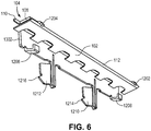
- cover 104 may include tabs 1206, 1208, 1210 and 1212 for securing cover 104 to base member 106.
- Tabs 1206, 1208, 1210 and 1212 may extend below cover 104 so that they can be secured to underlying base member 106.
- FIG. 5 shows tabs 1206 and 1208 as substantially straight, planar structures, to secure tabs 1206 and 1208 to base member 106, tabs 1206 and 1208 may be bent as will be discussed in more detail in reference to FIG. 6 and FIG. 7 .
- Tabs 1210 and 1212 may be positioned between tabs 1206 and 1208.
- Tabs 1210 and 1212 may be substantially straight structures which include barbed portions 1214 and 1216, respectively, at the ends. When cover 104 is positioned within base member 106, barbed portions 1214, 1216 catch on portions of base member 106 to secure cover 104 to base member 106.
- Base member 106 may include pegs 120 and 1408. Pegs 120 and 1408 may be used to secure base member 106 to a bridge as will be discussed in more detail in reference to FIG. 8 .
- each cartridge is independently attached to bridge 508.
- Middle cartridge 502 may be attached substantially at the attachment point 602 and leading and following cartridges 100 and 504 may be attached on either side adjacent thereto.
- bridge 508 may be flexible and can flex between a concave and a convex orientation.
- cross pieces 604 and 606 of bridge 508 may be formed from commercially available elastomeric nylon 12, polyurethane, or any other suitably resilient synthetic material.
- cross pieces 604 and 606 of mounting assembly 508 are substantially planar.
- Cartridges 100, 502 and 504 may be attached to cross pieces 604 and 606 using, for example, rivets 614.
- cartridges 100, 502 and 504 may be attached to cross pieces 604 and 606 using any other conventional attachment mechanism such as an adhesive, heat welding or a combination thereof.
- each of the cartridges 100, 502 and 504 is independent, the relative movement of one cartridge as the razor face becomes convexed is not affected by the other cartridges. Such movement is only constrained by the flexibility and resilience of cross pieces 604 and 606.
- the blades of the collection of cartridges define a plane when the razor in its rest state, e.g. no force is being exerted on the shaving head.
- cross pieces 604 and 606 may not be flexible such that the all cartridges are retained in a substantially rigid shaving plane.
- lubricating strip 610 may be applied to leading platform 608.
- each cartridge 100, 502 and 504 may also have its own lubricant as previously discussed to lubricate the area to be shaved before the next successive cartridge arrives.
- lubricating strip 610 may be replaced with flexible ribs that raise the hair in advance of leading cartridge 100.
- Handle interconnect 612 may be coupled to mounting assembly 508 to allow the shaving assembly to be coupled to a razor handle.
- Razor interconnect 612 may have any necessary configuration to allow it to connect to the variety of possible razor handles commercially available or subsequently designed.
- FIG. 10 shows a plan and exploded view of a razor head of one embodiment of the invention.
- Razor head 800 has a plurality of razor cartridges 810 forming a part thereof.
- Razor cartridges 810 comprise a blade 802, a base 804, and a cover 806 and may be manufactured as described in connection with FIGS. 4A-9 above.
- three cartridges 810 are coupled to a yoke 820.
- Yoke 820 is molded as a single unitary piece of material.
- the yoke is molded from thermoplastic.
- the selected material is EMS Grillflex ELG 5660 manufactured by EMS -GRIVORY. However, other thermoplastics may be used.
- Yoke 820 includes a bridge 822 integrally formed with a pair of cross pieces 824, which define attachment points 830 to receive cartridges 810.
- Bridge 822 couples to cross pieces 824 by a pair of living hinges 832.
- Living hinges have a thickness t, which permits the blade assembly to pivot about a living hinge in forward and backward directions through a first and second arc.
- t is equal to 1mm ⁇ 0.1.
- Other embodiments may have a greater or lesser t.
- the arc of pivot is limited by thickness t and the rigidity of the material forming the living hinges 832. By selecting an appropriate material for molding premature fatigue at the living hinges is avoided.
- attachments points 830 are a series of bores defined through cross pieces 824.
- yoke 820 includes a leading platform 826, which may define a well 828 to receive a lubricating material. In this manner, lubricating material is applied to skin in advance of a leading blade of a leading cartridge within the assembly.
- a handle attachment piece 834 is molded as part of yoke 820 in one embodiment of the invention, which permits a handle, such as a conventional stick handle or any other suitable handle to be attached to the blade assembly.
- cartridges 810 are as described in connection with FIGS. 4A-9 , in other embodiments, cartridges as described relative to FIGS. 1A-3B may be attached to the unitary yoke 820.
- the bases 804 of the cartridges 810 are molded integrally with the yolk 820.
- the embodiment described as reference to FIG. 10 includes exactly four unique parts (three of those parts are replicated three times for a total part count for a three cartridge blade assembly of ten). This part count is less than half a part count associated with the products of current market leaders Gillette and Schick.
- the Schick Hydro includes twenty-five distinct parts and the Gillette Fusion includes twenty-four distinct parts.
- the bases 804 are molded integrally with the yolk 820, the part count is reduced by the number of bases. Additionally, the manufacturing step of base attachment is avoided.
- FIG. 11 is a side view of shaving head of one embodiment of the invention. Certain dimensions of one embodiment in millimeters are shown.
- living hinges 832 allow cross pieces 824 and cartridges coupled thereto to pivot forward through an arc which in one embodiment is80 degrees.
- the Gillette Fusion has a maximum pivot arc of 55 degrees in a single direction.
- the same living hinges permit cartridges 810 and cross piece 824 to pivot backwards in arc of, for example, 75 degrees. In other embodiments, may be 60 degrees or 50 degrees and may be selected to be, for example, 50 or 40 degrees.
- the forward and backward arcs are defined from a rest position, the rest position being the position of the head when on force is applied.
- FIGS. 12A-12C are depictions of an alternative embodiment of the invention having a single cartridge associated with a unitary yoke.
- a shaving head 900 includes a yoke 920 having a bridge 922 that couples to cross pieces 924.
- Cross pieces 924 define an attachment point for a single cartridge 810.
- cross pieces 924 may define a bore to receive integrally molded attachment peg 838 and coupling may be by heat welding, adhesion or any other suitable manner.
- Yoke 920 may include a handle attachment piece 934 to allow the assembly to be coupled to a shaving razor handle.
- the long dimension of the cartridge is 39.6 millimeters.
- reduced sized cartridges being for example, 19.8 millimeters are within the scope and contemplation of the invention. Other sizes are also within the scope and contemplation of the invention.
- FIG. 12B shows a side view of a single cartridge embodiment of the invention. This view reveals the cross dimension of one embodiment of the cartridge is 3.81 millimeters.
- FIG. 12C shows a top plan view of a single cartridge embodiment. In this view, the dimension of the cover blade assembly can be seen to be 3.2 millimeters. These small dimensions permit the razor to function effectively in tight spaces such as around the nose.
Description
- A personal care item, more particularly a shaving device.
- A diversity of shaving means are available on the market, for example manually operated, electric shavers, multiple use and disposable shaving devices. Typically, such shaving devices include a gripping handle for conveniently holding one or more cutting blades and a respective cartridge bearing one or more or those blades, secured within. Many of these devices include numerous blades and a host of small part such the manufacture is complex and expensive. Moreover, the resulting products are often bulky making it difficult to shave in corners such as around the nose. Additionally, users often find it difficult to maintain contact between the cutting blades and the skin and the razor traverses the myriad angles of the face.
- The document
FR 2 433 396 A1 - In the document
US 6,311,400 B1 there is disclosed a safety razor including a suspension structure for supporting a blade unit on a handle so that the blade unit is able to pivot. - The document
WO 2010/010517 A2 discloses a shaving assembly comprising several cartridges being mounted to a yoke and several flexible crosspieces. - According to the invention, there is provided a shaving razor as defined by independent claim 1.
- Further advantageous features are comprised in the dependent claims.
- The embodiments of the invention are illustrated by way of example and not by way of limitation in the figures of the accompanying drawings in which like references indicate similar elements. It should be noted that references to "an" or "one" embodiment of the invention in this disclosure are not necessarily to the same embodiment, and they mean at least one.
-
FIGS. 1A and 1B are schematic diagrams of a rear perspective view and a front perspective view, respectively, of a shaving assembly of an embodiment of the invention; -
FIG. 2 is an exploded view of a razor assembly in an embodiment of the invention; -
FIGS. 3A and3B are schematic side views of a shaving assembly of an embodiment of the invention in a non-flexed and convex orientation, respectively; -
FIG. 4A illustrates a perspective view of an embodiment of a shaving cartridge. -
FIG. 4B illustrates a cross sectional view of the shaving cartridge ofFIG. 4A along line A, A'. -
FIG. 5 illustrates a perspective view of the cover and blade illustrated inFIG. 4A . -
FIG. 6 illustrates a bottom perspective view of the cover and blade illustrated inFIG. 5 . -
FIG. 7 illustrates a rear perspective view of the shaving cartridge illustrated inFIG. 4A . -
FIG. 8 illustrates an exploded view of one embodiment of a shaving assembly. -
FIG. 9A illustrates a rear perspective view of the shaving assembly ofFIG. 8 . -
FIG. 9B illustrates a front perspective view of the shaving assembly ofFIG. 8 . -
FIG. 10 is a plan and exploded view of a razor head of one embodiment of the invention. -
FIG. 11 is a side view of shaving head of one embodiment of the invention. -
FIGS. 12A-12C illustrate an alternative embodiment of the invention having a single cartridge associated with a unitary yoke. - Several embodiments of the invention with reference to the appended drawings are now explained. Whenever the shapes, relative positions and other aspects of the parts described in the embodiments are not clearly defined, the scope of the invention is not limited only to the parts shown, which are meant merely for the purpose of illustration.
-
FIGS. 1A and 1B are schematic diagrams of a rear perspective view and a front perspective view respectively of a shaving assembly of one embodiment of the invention. A plurality ofindependent cartridges cross pieces 202 of a cartridge support. Cartridge support also includes abridge 204 spanning betweencross pieces 202.Bridge 204 is coupled to eachcross piece 202 at anattachment point 216. - In the shown embodiment, three independent cartridges, leading
cartridge 260,middle cartridge 250 and followingcartridge 240 are used. In one embodiment, each cartridge is independently attached to across piece 202 withmiddle cartridge 250 being attached substantially at theattachment point 216 and leading and followingcartridges Figure 2 below. Generally,cross pieces 202 are flexible and can flex between a concave and a convex orientation. This is discussed more fully below with reference toFigures 3A and3B . At rest, e.g., when no forced is applied,cross pieces 202 are substantially planar.Cartridges cross pieces 202 using adhesive, rivets, heat welding or any conventional attachment mechanism or a combination thereof. The positioning of the cartridges alongcross piece 202 and in particular the finite space "d" between each cartridge pair (better shown inFigures 3A and3B ) dictates the amount of concavity that a face of the razor can achieve before contact between the adjacent cartridges prevents further movement. Because each of thecartridges cross piece 202. - As used herein, "leading" refers to earlier in position relative to the direction of shaving. Thus, leading
cartridge 260 encounters an area to be shaved beforemiddle cartridge 250 as the assembly is pulled along the shaving area. In one embodiment, the shaving assembly includes a leadingplatform 214 on which may be disposed alubricating strip 280. Leadingplatform 214 may be attached to or formed withcross pieces 202. Lubricatingstrip 280 is positioned to release lubrication in advance of leadingcartridge 260. - In some embodiments, each cartridge may also have its own
lubricating strip 208, which lubricates the area to be shaved before the next successive cartridge arrives. Leadingplatform 214 may includeperforations 224 to improve the adhesion of the lubricatingstrip 208. In an alternative embodiment, lubricatingstrip 208 may be replaced with flexible ribs or mirror fans that raise the drain in advance of leadingcartridge 260. Ahandle interconnect 272 is coupled to thebridge 204 to allow the shaving assembly to be coupled to a razor handle.Handle interconnect 272 may provide for reciprocation of the entire assembly when attached to a handle.Razor interconnect 272 may have any necessary configuration to allow it to connect to the myriad possible razor handles commercially available or subsequently designed. -
FIG. 2 is an exploded view of the shaving assembly in one embodiment of the invention. Leadingcartridge 260 is shown exploded. Each cartridge includes ablade 306 and a carrier having a base 302 and acap 304, which together retain theblade 306. Thebase 302 andcap 304 may be injection molded out of any suitable plastic or other material, for example, extruded from plastic or aluminum. In one embodiment,base 302 is integrally formed with mountingpegs 310 extending therefrom. Mounting pegs 310 engageholes 312 incross piece 202 and may be heat welded or otherwise adhered therein.Cap 304 is designed to snap fit intobase 302 to retainblade 306.Base 302 defineschannels 308 through which shaved hair may pass without clogging or blockingblade 306. - In various embodiments,
cross piece 202 may be formed from commercially available elastomeric nylon 12, polyurethane, or any other suitably resilient synthetic material. Generally, it is desirable forcross piece 202 to have sufficient resilience to deform and return to its generally planar original state for at least 8000 cycles. Resilience of 10,000 cycles or more is preferred. In some embodiments,cross piece 202 andbridge 204 are molded or extruded integrally as a unit. In some other embodiments,cross piece 202 andbase 302 are molded integrally as a unit. It should be noted that when thebases 302 of each cartridge can be formed integrally as one piece with each other and that in such case there is no need for abridge 204. -
FIGS. 3A and3B are schematic side views of a shaving assembly an embodiment of the invention, in an unflexed and a convexed orientation, respectively. Across member 402 is coupled to abridge 404 and retainsindependent cartridges cross members 402 to flex aroundattachment point 416 into either a concave or a convex orientation. Finite space "d" exists between adjacent cartridge pairs 440, 450 and 460. The finite space "d" dictates the amount by whichcross member 402 can flex to concave the face of the shaving assembly. Ascross member 402 flexes into a concave orientation adjacent cartridges come into contact and prevent further concavity. In the absence of a finite space "d", cross member 402 (once assembled) will only be able to flex in a direction to cause the face to become convexed. The convex orientation assists in shaving a tight area, such as under a user's nose while the concave orientation assists in shaving around angular portions, such as the chin. Generally speaking, the need for convex flexibility exceeds that for concave flexibility. In the shown embodiment, leadingplatform 414 supports a series of micro ribs, which may be formed of an elastomeric material and are designed to lift the hair in advance of the blade from leadingcartridge 460. It should be understood that the micro ribs could be replaced in whole or in part by a lubricating strip on the leadingplatform 414. -
FIG. 3B showscross member 402 flexed in a convexed, orientation leading aboutattachment point 416. As previously noted, this orientation makes it easier to get into tight spaces, such as around a user's nose. Notably, leadingplatform 414 provides leverage to facilitate this flexion as a user presses the assembly against the area to be shaved wherein the leadingplatform 414 provides a lever arm to initiate bending aboutattachment point 416. -
FIG. 4A illustrates a perspective view of an embodiment of a shaving cartridge.Shaving cartridge 100 may includeblade 102,cover 104 andbase member 106. In some embodiments,blade 102 may be a razor blade. Cover 104 may be secured toblade 102. Cover 104 may further be attached tobase member 106 and retainblade 102 in place withincartridge 100. Cover 104 is positioned overblade 102 such that during shaving,cover 104 and cuttingedge 112 ofblade 102 contact the user's skin. In this aspect, cover 104 defines a recessedportion 118 along cuttingedge 112 so that a portion of cuttingedge 112 is exposed to the user's skin. Cover 104 may serve as a protective cover overblade 102. - Cover 104 defines a
channel 114 adjacent toblade 102. In one embodiment, the channel is generally V-shaped. The channel may be defined by afirst panel 108 and asecond panel 110. In addition to serving as a protective cover, cover 104 may be dimensioned to spread the pressure of cuttingedge 112 across the skin better than conventional razor blade cartridges and improvecutting edge 112 glide across the skin so as to reduce nicks and cuts. These advantages are achieved, at least in part, by decreasing the surface area ofcover 104 and cuttingedge 112 contacting the user's skin by approximately 60% as compared to the conventional razor blade cartridges. Stated slightly differently, if one were to draw a bounding box around the cartridge in the shaving plane, the area above the channel represents 60% of the area within the bounding box. - Cover 104 with
blade 102 attached thereto is positioned onbase member 106 such that during a shaving operation,upper edge 116 ofsecond panel 110 and cuttingedge 112 define cuttingplane 122. Portions ofcover 104 withinchannel region 114 remain raised above cuttingplane 122 during shaving and therefore do not contact the user's skin. Additionally,upper edge 116 stretches the skin to increase the closeness of the shave. - Cover 104 may be made of any material suitable for contacting a user's skin during shaving. Representatively, cover 104 may be made of a metal material, for example, aluminum. In still further embodiments, cover 104 may be made of other materials such as a plastic material. In some embodiments, cover 104 may be stamped from an aluminum sheet as a single unit. In other embodiments, cover 104 may be formed by any process known in the art such as injection molding, machining or any other manufacturing process suitable for generating the desired features of
cover 104. - In embodiments where
cover 104 is made of a metal material, a lubricating coating may be applied to cover 104 to facilitate movement ofcartridge 100 across the user's skin. Representatively, an electrostatic spray coating method may be used to apply solids such as telomers as dispersions in water, alcohols, freons, or various fluorocarbon liquids, for example, an aqueous dispersion of tetrofluoroethylene telomer alongupper edge 116 ofcover 104. Alternatively, a lubricating strip infused with a lubricating material, for example, aloe vera and/or coconut milk, may be attached to cover 104. Any of the above discussed lubricating coatings and/or materials may further be disposed on portions ofbase member 106 contacting the user's skin. - Attachment of
cover 104 andblade 102 tobase member 106 may be achieved by weldingcover 104 directly toblade 102. Representatively, cover 104 may be spot welded toblade 102 at various points along a length dimension ofblade 102. Cover 104 may then be attached tobase member 106 as will be discussed in more detail in reference toFIG. 7 . The use ofcover 104 to attachblade 102 tobase member 106 as disclosed herein, as opposed to attachingblade 102 directly onbase member 106, results in a morerigid cartridge 100 that maintainsblade 102 shape. It is believed that this results in a longer lasting blade having better gliding capabilities. -
Base member 106 may include mountingpeg 120 to facilitate attachment ofbase member 106 to a bridge as will be discussed in further detail in reference toFIG. 7 . In one embodiment,base member 106 is integrally formed with mountingpeg 120 extending therefrom.Base member 106 may further includeelongated aperture 124 through which shaved hair may pass without clogging or blockingblade 102. -
FIG. 4B illustrates a cross sectional view of the shaving cartridge ofFIG. 4A along line A, A'.FIG. 4B shows shavingcartridge 100 ofFIG. 4A rotated so that cuttingedge 112 is positioned alongskin 126 to shavehairs 128 extending therefrom. From this view, it can be seen that cuttingplane 122 is defined byupper edge 116 ofsecond panel 110 and cuttingedge 112. During shaving ofhairs 128 extending fromskin 126,channel 114 ofcover 104 is raised aboveskin 126 such that onlyupper edge 116 ofcover 104 and cuttingedge 112 slide along the skin. In some embodiments,channel 114 may help to retain lubricating and/or moisturizing fluids used during shaving, such as soaps, foams, water, etc., againstskin 126. Such feature may further improve the glide ofcartridge 100 againstskin 126 and the condition ofskin 126 in general after shaving. -
FIG. 5 illustrates a perspective view of the cover and blade illustrated inFIG. 4A . As previously discussed,cover 104 may includefirst panel 108 andsecond panel 110. Recess 118 may be formed withinfirst panel 108 to expose a portion of cuttingedge 112 ofblade 102 attached thereto. From this view, a depth ofchannel region 114 with respect to cuttingplane 122 formed byedge 116 and cuttingedge 112 can be more clearly seen. In particular, it can be seen that only edge 116 ofsecond panel 110 and cuttingedge 112 are within cuttingplane 122. As a result, during shaving, only edge 116 and cuttingedge 112 contact the user's skin, whilechannel region 114 ofcover 104 remains raised above the surface of the skin. - Cover 104 may further include
stop members first panel 108.Stop members edge 112. In this aspect, stopmembers blade 102 and, in particular, cuttingedge 112, withincover 104.Stop members cover 104. - In addition,
cover 104 may includetabs cover 104 tobase member 106.Tabs cover 104 so that they can be secured tounderlying base member 106. AlthoughFIG. 5 showstabs tabs base member 106,tabs FIG. 6 andFIG. 7 .Tabs tabs Tabs barbed portions cover 104 is positioned withinbase member 106,barbed portions base member 106 to securecover 104 tobase member 106. -
FIG. 6 illustrates a bottom perspective view of the cover and blade illustrated inFIG. 5 . From this view, it can be seen thatcover 104 further includes backplate 1302 extending fromsecond panel 110.Back plate 1302 extends belowblade 102 and along a back side of base member 106 (seeFIG. 7 ). In this aspect,back plate 1302 helps to alignblade 102 and cover 104 withbase member 106.Tabs back plate 1302. InFIG. 6 ,tabs cover 104 tobase member 106. -
FIG. 7 illustrates a rear perspective view of the shaving cartridge illustrated inFIG. 4A . From this view, the manner in which cover 104 is attached tobase member 106 can be seen. In particular, to attachcover 104 tobase member 106,back plate 1302 ofcover 104 is positioned along a back side ofbase member 106.Tabs base member 106.Tabs slots bracket 1406 along an underside ofbase member 106.Barbs tabs slots tabs -
Base member 106 may includepegs Pegs base member 106 to a bridge as will be discussed in more detail in reference toFIG. 8 . -
FIG. 8 illustrates an exploded view of one embodiment of a shaving assembly.Shaving assembly 500 may include a plurality ofcartridges Cartridge 100 may be substantially the same ascartridge 100 described in reference toFIG. 4A .Cartridges cartridge 100. InFIG. 8 ,cartridge 100 is shown exploded. - Each cartridge includes
cover 104 andbase member 106, which together retainblade 102 withincartridge 100. In one embodiment,base member 106 is integrally formed with mountingpegs 120 and 408 extending therefrom. Mounting pegs 120 and 408 engageholes 506 inbridge 508 and may be heat welded or otherwise adhered therein. In various embodiments,bridge 508 may be formed from commercially available elastomeric nylon 12, polyurethane, or any other suitably resilient synthetic material. It should be noted thatbase member 106 of each cartridge can be formed integrally as one piece with each other.Bridge 508 may in turn be attached to a handle interconnect member to attachcartridges FIGS. 9A and9B . -
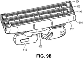
FIGS. 9A and9B illustrate a rear perspective view and a front perspective view, respectively, of the shaving assembly ofFIG. 8 . A plurality ofindependent cartridges FIG. 8 are coupled to bridge 508. - In the illustrated embodiment, three independent cartridges, leading
cartridge 100,middle cartridge 502 and followingcartridge 504 are used. In one embodiment, each cartridge is independently attached to bridge 508.Middle cartridge 502 may be attached substantially at theattachment point 602 and leading and followingcartridges - In some embodiments,
bridge 508 may be flexible and can flex between a concave and a convex orientation. In this aspect, crosspieces bridge 508 may be formed from commercially available elastomeric nylon 12, polyurethane, or any other suitably resilient synthetic material. At rest, e.g., when no forced is applied, crosspieces assembly 508 are substantially planar.Cartridges pieces cartridges pieces cartridges cross pieces pieces - As noted above the leading
cartridge 100 encounters an area to be shaved beforemiddle cartridge 502 as the assembly is pulled along the shaving area. In one embodiment, the shaving assembly may include leadingplatform 608. Leadingplatform 608 may be attached to, or formed with,cross pieces strip 610 is positioned to release lubrication in advance of leadingcartridge 100. - In some embodiments, lubricating strip 610 (see
FIG. 9B ) may be applied to leadingplatform 608. In addition or in the alternative, eachcartridge strip 610 may be replaced with flexible ribs that raise the hair in advance of leadingcartridge 100. -
Handle interconnect 612 may be coupled to mountingassembly 508 to allow the shaving assembly to be coupled to a razor handle.Razor interconnect 612 may have any necessary configuration to allow it to connect to the variety of possible razor handles commercially available or subsequently designed. -
FIG. 10 shows a plan and exploded view of a razor head of one embodiment of the invention.Razor head 800 has a plurality ofrazor cartridges 810 forming a part thereof.Razor cartridges 810 comprise ablade 802, abase 804, and acover 806 and may be manufactured as described in connection withFIGS. 4A-9 above. In the shown embodiment, threecartridges 810 are coupled to ayoke 820.Yoke 820 is molded as a single unitary piece of material. In one embodiment, the yoke is molded from thermoplastic. In one embodiment, the selected material is EMS Grillflex ELG 5660 manufactured by EMS-GRIVORY. However, other thermoplastics may be used. -
Yoke 820 includes abridge 822 integrally formed with a pair ofcross pieces 824, which defineattachment points 830 to receivecartridges 810.Bridge 822 couples to crosspieces 824 by a pair of living hinges 832. Living hinges have a thickness t, which permits the blade assembly to pivot about a living hinge in forward and backward directions through a first and second arc. In one embodiment t is equal to 1mm ± 0.1. Other embodiments may have a greater or lesser t. The arc of pivot is limited by thickness t and the rigidity of the material forming the living hinges 832. By selecting an appropriate material for molding premature fatigue at the living hinges is avoided. In one embodiment, attachments points 830 are a series of bores defined throughcross pieces 824. Cross pieces may have the same flexibility characteristics as described with other embodiments above. This permits attachment pegs of base 804 (not shown inFIG. 10 ) to be heat welded within thebore 830. In one embodiment, eachcartridge 810 has a length dimension of 39.6 millimeters which spans between thecross pieces 824. Other dimensions are contemplated as within the scope of other embodiments of the invention. - In some embodiments,
yoke 820 includes a leadingplatform 826, which may define a well 828 to receive a lubricating material. In this manner, lubricating material is applied to skin in advance of a leading blade of a leading cartridge within the assembly. Also molded as part ofyoke 820 in one embodiment of the invention is ahandle attachment piece 834, which permits a handle, such as a conventional stick handle or any other suitable handle to be attached to the blade assembly. Notably, while in someembodiments cartridges 810 are as described in connection withFIGS. 4A-9 , in other embodiments, cartridges as described relative toFIGS. 1A-3B may be attached to theunitary yoke 820. In another embodiment, thebases 804 of thecartridges 810 are molded integrally with theyolk 820. - From a manufacturing standpoint, the embodiment described as reference to
FIG. 10 includes exactly four unique parts (three of those parts are replicated three times for a total part count for a three cartridge blade assembly of ten). This part count is less than half a part count associated with the products of current market leaders Gillette and Schick. By way of example, the Schick Hydro includes twenty-five distinct parts and the Gillette Fusion includes twenty-four distinct parts. In embodiments in which thebases 804 are molded integrally with theyolk 820, the part count is reduced by the number of bases. Additionally, the manufacturing step of base attachment is avoided. -
FIG. 11 is a side view of shaving head of one embodiment of the invention. Certain dimensions of one embodiment in millimeters are shown. In one embodiment, living hinges 832 allowcross pieces 824 and cartridges coupled thereto to pivot forward through an arc which in one embodiment is80 degrees. For purposes of comparison The Gillette Fusion has a maximum pivot arc of 55 degrees in a single direction. The same living hingespermit cartridges 810 andcross piece 824 to pivot backwards in arc of, for example, 75 degrees. In other embodiments, may be 60 degrees or 50 degrees and may be selected to be, for example, 50 or 40 degrees. The forward and backward arcs are defined from a rest position, the rest position being the position of the head when on force is applied. However, a greater arc of pivot increases the range of angles of the handle over which theblades 802 will remain on a user's skin in an effective position. In one embodiment, crosspieces 824 are also flexible, such that the overall face of the razor may flex to be concave or convex as described above in connection withFIGS. 3A-3B . In an alternative embodiment, crosspieces 824 may not be flexible such that while the head can pivot about the living hinges the all cartridges are retained in a shaving plane. -
FIGS. 12A-12C are depictions of an alternative embodiment of the invention having a single cartridge associated with a unitary yoke. A shavinghead 900 includes ayoke 920 having abridge 922 that couples to crosspieces 924.Cross pieces 924 define an attachment point for asingle cartridge 810. For example, crosspieces 924 may define a bore to receive integrally moldedattachment peg 838 and coupling may be by heat welding, adhesion or any other suitable manner.Yoke 920 may include ahandle attachment piece 934 to allow the assembly to be coupled to a shaving razor handle. In the shown embodiment, the long dimension of the cartridge is 39.6 millimeters. However, reduced sized cartridges, being for example, 19.8 millimeters are within the scope and contemplation of the invention. Other sizes are also within the scope and contemplation of the invention. -
FIG. 12B shows a side view of a single cartridge embodiment of the invention. This view reveals the cross dimension of one embodiment of the cartridge is 3.81 millimeters.FIG. 12C shows a top plan view of a single cartridge embodiment. In this view, the dimension of the cover blade assembly can be seen to be 3.2 millimeters. These small dimensions permit the razor to function effectively in tight spaces such as around the nose. - While explicit dimensions are shown and described in connection with various embodiments, it is within the scope and contemplation to change those dimensions. Thus, the actual dimensions may be larger or smaller than the dimensions detailed. However, it has been found that the dimensions shown yield a quality product providing an exceptional shave.
Claims (13)
- A shaving razor comprising:a yoke (820) molded as a single piece, the yoke (820) including a bridge (822) and a pair of cross pieces (824) coupled to the bridge (822) each by a respective living hinge (832); anda plurality of cartridges (810) each having a razor blade (802) coupled to the yoke (820) to span between the crosspieces (824),wherein the living hinges (832) are oriented to permit the cartridges (810) to pivot in a forward and backward direction andwherein the crosspieces are flexible to allow the discrete cartridges to adopt a convex configuration during use.
- The shaving razor of claim 1 wherein the living hinge (832) permits a range of motion of the blade assembly greater than 120°.
- The shaving razor of claim 2 wherein the living hinges (832) permit a forward pivot through a first arc of greater than 50 degrees and backward pivot through a second arc greater than 50 degrees, both the first and second arcs defined relative to a rest position.
- The shaving razor of claim 1 wherein the yoke (820) further comprises:
a leading platform to contact a user's skin in advance of a leading razor blade. - The shaving razor of claim 4 wherein the leading platform defines a well.
- The shaving razor of claim 5 further comprising:
a lubricating material disposed within the well. - The shaving razor of claim 1 wherein the cartridge comprises:
a base; and
a cover coupled to the blade and the base, the cover defining a channel that lags a cutting edge of the blade. - The apparatus of claim 7 wherein the channel is defined to be generally v-shaped with a first side and a second side, the first side adjacent to the blade and substantially parallel thereto and the second side at an acute angle thereto and having a second edge, the second edge and the cutting edge defining a shaving plane.
- The apparatus of claim 7 wherein the cover is mounted to the blade with spot welds.
- The apparatus of claim 7 wherein the cover defines a recessed region exposing the cutting edge.
- The apparatus of claim 7 further comprising:
a lubricating material coupled to the cover. - The apparatus of claim 7 wherein the cover comprises a metal material.
- The apparatus of claim 7 wherein the cover further comprises:a support member having a back portion extending from the cover to the base member; andat least one tab portion attached to the base member.
Applications Claiming Priority (2)
| Application Number | Priority Date | Filing Date | Title |
|---|---|---|---|
| US13/173,911 US9144914B2 (en) | 2011-06-30 | 2011-06-30 | Razor cartridge with reduced part count and expanded range of motion |
| PCT/US2012/044436 WO2013003484A2 (en) | 2011-06-30 | 2012-06-27 | Razor cartridge with reduced part count and expanded range of motion |
Publications (3)
| Publication Number | Publication Date |
|---|---|
| EP2726259A2 EP2726259A2 (en) | 2014-05-07 |
| EP2726259A4 EP2726259A4 (en) | 2016-06-08 |
| EP2726259B1 true EP2726259B1 (en) | 2020-04-15 |
Family
ID=47389140
Family Applications (1)
| Application Number | Title | Priority Date | Filing Date |
|---|---|---|---|
| EP12803906.2A Active EP2726259B1 (en) | 2011-06-30 | 2012-06-27 | Razor cartridge with reduced part count and expanded range of motion |
Country Status (8)
| Country | Link |
|---|---|
| US (3) | US9144914B2 (en) |
| EP (1) | EP2726259B1 (en) |
| JP (1) | JP6247208B2 (en) |
| KR (1) | KR101945906B1 (en) |
| CN (1) | CN103764354B (en) |
| HK (1) | HK1197210A1 (en) |
| IL (1) | IL230037B (en) |
| WO (1) | WO2013003484A2 (en) |
Families Citing this family (39)
| Publication number | Priority date | Publication date | Assignee | Title |
|---|---|---|---|---|
| GB2462086A (en) * | 2008-07-22 | 2010-01-27 | Alon Coresh | Articulated Shaving Set |
| US8533959B2 (en) * | 2010-10-11 | 2013-09-17 | The Gillette Company | Cartridges and razors with trimming wing |
| US9144914B2 (en) * | 2011-06-30 | 2015-09-29 | Rolling Razor, Inc. | Razor cartridge with reduced part count and expanded range of motion |
| US9156175B2 (en) * | 2011-12-09 | 2015-10-13 | The Gillette Company | Fluid applicator for a personal-care appliance |
| USD707885S1 (en) * | 2013-02-28 | 2014-06-24 | The Gillette Company | Shaving razor cartridge |
| US9457486B2 (en) | 2013-03-13 | 2016-10-04 | Rolling Razor, Inc | Shaving cartridge with individual blade guards |
| WO2014209776A1 (en) * | 2013-06-27 | 2014-12-31 | Shavelogic, Inc. | Shaving system |
| PL3083163T3 (en) | 2013-12-18 | 2020-06-01 | Bic-Violex S.A. | A shaving blade cartridge |
| KR101590595B1 (en) * | 2014-01-15 | 2016-02-01 | 주식회사 하이원화이어 | Ceramic razor blade and ceramic razor blade assembly having the same |
| US11077570B2 (en) | 2014-01-31 | 2021-08-03 | Dryfhout Properties, Llc | Flexible back shaver |
| US10500744B1 (en) | 2014-01-31 | 2019-12-10 | Dryfhout Properties, Llc | Safety razor with plurality of comb and integrated blade groups |
| US10315322B1 (en) | 2016-05-17 | 2019-06-11 | Dryfhout Properties, Llc | Method of using a back shaver handle |
| US10131062B1 (en) | 2014-01-31 | 2018-11-20 | Dryfhout Enterprises, Llc | Body shaver with comb and blade |
| US9616584B2 (en) * | 2014-03-20 | 2017-04-11 | Rolling Razor, Inc. | Shaving razor and shaving handle with an interconnection mechanism |
| US9630332B2 (en) * | 2014-09-29 | 2017-04-25 | Alon Leon Coresh | Shaving razor with one or more reciprocating blades |
| US20160158948A1 (en) * | 2014-12-08 | 2016-06-09 | The Gillette Company | Razor Cartridge Guard Structure |
| US20160158949A1 (en) * | 2014-12-08 | 2016-06-09 | The Gillette Company | Razor Cartridge Guard Structure |
| PL3191268T3 (en) | 2015-12-01 | 2020-07-13 | Bic-Violex S.A. | Shaving razors and shaving cartridges |
| BR112018068899A2 (en) | 2016-03-18 | 2019-01-22 | Personal Care Marketing And Res Inc | razor blade cartridge |
| US10543609B2 (en) | 2016-05-17 | 2020-01-28 | Dryfhout Properties, Llc | Elevated shaver |
| US9937629B1 (en) | 2016-05-17 | 2018-04-10 | Dryfhout Enterprises, Llc | Two-point discrimination safety razor assembly |
| US10493643B1 (en) | 2016-05-17 | 2019-12-03 | Dryfhout Properties, Llc | Leveled back shaver |
| USD877983S1 (en) | 2016-09-09 | 2020-03-10 | The Gillette Company Llc | Shaving razor cartridge |
| EP3292965B1 (en) | 2016-09-09 | 2021-05-26 | The Gillette Company LLC | Shaving razor cartridge and method of assembling |
| US9993931B1 (en) | 2016-11-23 | 2018-06-12 | Personal Care Marketing And Research, Inc. | Razor docking and pivot |
| US11117278B2 (en) | 2017-06-06 | 2021-09-14 | The Gillette Company Llc | Shaving razor cartridge |
| KR101876233B1 (en) * | 2017-09-29 | 2018-07-10 | 주식회사 도루코 | Razor cartridge assembly |
| US11541560B2 (en) * | 2018-03-01 | 2023-01-03 | Rolling Razor, Inc. | Precision razor with low cost assembly |
| US10500746B2 (en) | 2018-05-07 | 2019-12-10 | Leon Coresh | Reciprocating razor with living hinge interconnections |
| USD884971S1 (en) | 2019-02-27 | 2020-05-19 | Pcmr International Ltd | Razor cartridge |
| USD884970S1 (en) | 2019-02-27 | 2020-05-19 | PCMR International Ltd. | Razor cartridge guard |
| USD884969S1 (en) | 2019-02-27 | 2020-05-19 | Pcmr International Ltd | Combined razor cartridge guard and docking |
| US11351689B2 (en) * | 2019-03-14 | 2022-06-07 | Neckrazor LLC | Razor device |
| USD921984S1 (en) | 2019-03-19 | 2021-06-08 | The Gillette Company Llc | Shaving razor cartridge |
| US11104017B2 (en) * | 2019-05-31 | 2021-08-31 | Conair Corporation | Hair cutter blade gap adjustment system |
| JP6600762B1 (en) * | 2019-07-31 | 2019-10-30 | 株式会社貝印刃物開発センター | Razor head |
| US11167437B2 (en) | 2019-12-02 | 2021-11-09 | Leon Coresh | Reciprocating razor assembly with different amplitudes of motion |
| EP3858565A1 (en) * | 2020-01-30 | 2021-08-04 | BIC Violex S.A. | Modular frame for shaving head |
| US11000960B1 (en) | 2020-11-16 | 2021-05-11 | Personal Care Marketing And Research, Inc. | Razor exposure |
Family Cites Families (110)
| Publication number | Priority date | Publication date | Assignee | Title |
|---|---|---|---|---|
| US3092904A (en) * | 1960-05-09 | 1963-06-11 | Bruecker John | Movable cutter for a dry shaver having saw tooth design cutting edge |
| US3138865A (en) * | 1960-08-13 | 1964-06-30 | Meyer Eugen | Safety razor having skin-stretching and guiding means |
| US3137940A (en) * | 1960-12-30 | 1964-06-23 | Curci Alfred | Disposable combination safety-razor and blade magazine |
| US3412464A (en) * | 1967-01-16 | 1968-11-26 | Karl M. Keck | Razor having a rotative blade holder |
| GB1460732A (en) * | 1973-03-01 | 1977-01-06 | Gillette Co | Safety razor |
| US4094063A (en) * | 1976-12-15 | 1978-06-13 | The Gillette Company | Razor assembly with pivotally mounted cartridge |
| US4170821A (en) | 1977-12-02 | 1979-10-16 | Warner-Lambert Company | Razor cartridges |
| GB2030909A (en) * | 1978-08-15 | 1980-04-16 | Wilkinson Sword Ltd | Razors |
| EP0020816A1 (en) | 1979-06-19 | 1981-01-07 | The Gillette Company | Shaving razor assembly |
| US4392303A (en) * | 1979-12-31 | 1983-07-12 | Warner-Lambert Company | One-piece razor handle |
| US4461078A (en) * | 1982-02-01 | 1984-07-24 | Carreker Reginald V | Styling razor |
| US4459744A (en) * | 1982-02-04 | 1984-07-17 | Alan K. Roberts | Razor blade apparatus and method |
| US4534110A (en) * | 1982-12-28 | 1985-08-13 | David Mall | Triple-edge safety razor and blade |
| US4501066A (en) * | 1983-04-11 | 1985-02-26 | Sceberras Conrad T | Dual headed razor system |
| US4516320A (en) | 1983-04-28 | 1985-05-14 | Warner-Lambert Company | Dynamic razor |
| US4641429A (en) * | 1984-12-24 | 1987-02-10 | Abatemarco Michael R | Razor blade cartridge unit with dual blades |
| US4720917A (en) * | 1985-09-13 | 1988-01-26 | Solow Terry S | Flexible blade contour razor |
| US4932122A (en) | 1987-12-21 | 1990-06-12 | The Gillette Company | Safety razor blade assembly |
| US4993153A (en) * | 1989-10-27 | 1991-02-19 | Henry James G | Multiple blade stand up razor |
| AR244587A1 (en) * | 1989-11-17 | 1993-11-30 | Warner Lambert Co | Pivoting safety razor assembly |
| US4989328A (en) * | 1990-03-16 | 1991-02-05 | Daniel Sokoloff | Dual headed razor assembly |
| US5152064A (en) | 1991-09-09 | 1992-10-06 | Johnston William M | Shaving method and apparatus |
| GB9208098D0 (en) | 1992-04-13 | 1992-05-27 | Gillette Co | Razor with movable cartridge |
| US5206994A (en) | 1992-06-04 | 1993-05-04 | Catherine Lin | Collapsible razor |
| USD343922S (en) * | 1992-10-13 | 1994-02-01 | Ahlgren Erick L | Disposable razor |
| US5307564A (en) * | 1992-12-01 | 1994-05-03 | Schoenberg Frederic D | Safety razor |
| US6082007A (en) * | 1993-02-22 | 2000-07-04 | Andrews; Edward A. | In-line bi-directional manual shaving razors |
| US6141875A (en) * | 1993-02-22 | 2000-11-07 | Andrews; Edward A. | In-line shaving razors with twin pivoting heads |
| US6161288A (en) | 1993-02-22 | 2000-12-19 | Andrews; Edward A. | Four blade bi-directional razor structure with flexible guard system |
| US5343622A (en) * | 1993-02-22 | 1994-09-06 | Andrews Edward A | Bi-directional razor device |
| US6434828B1 (en) | 1993-02-22 | 2002-08-20 | Edward A. Andrews | In-line razor device with twin pivoting heads |
| AU6698194A (en) | 1993-08-04 | 1995-02-28 | Warner-Lambert Company | Dynamic shaving system |
| US6212777B1 (en) | 1993-09-29 | 2001-04-10 | The Gillette Company | Safety razors |
| US5426853A (en) | 1994-03-09 | 1995-06-27 | Mcninch; Herbie | Method of shaving and improved shaver |
| US5546660A (en) * | 1994-09-30 | 1996-08-20 | Warner-Lambert Company | Dynamic razor head |
| US5450671A (en) * | 1994-10-21 | 1995-09-19 | Harshman; David | Hair trimming device |
| IL116684A (en) | 1996-01-05 | 1998-12-06 | Mepro Epilady Ltd | Shaving device |
| GB9600818D0 (en) | 1996-01-16 | 1996-03-20 | Gillette Co | Safety razors |
| US5953825A (en) * | 1996-01-16 | 1999-09-21 | The Gillette Company | Safety razors |
| WO1997035693A2 (en) | 1996-03-27 | 1997-10-02 | Warner-Lambert Company | Shaving system with uniform shaving forces |
| US5711076A (en) | 1996-03-27 | 1998-01-27 | The Gillette Company | Shaving system with improved guard structure |
| US5781997A (en) | 1997-01-17 | 1998-07-21 | Warner-Lambert Company | Ultra-flexible shaving cartridge |
| US6243951B1 (en) * | 1997-02-18 | 2001-06-12 | The Gillette Company | Safety razors |
| GB9715501D0 (en) * | 1997-07-22 | 1997-10-01 | Gillette Co | Safety razors |
| US6125857A (en) * | 1998-07-13 | 2000-10-03 | Silber; David | Dual sideburn trimmer |
| US6308416B1 (en) * | 1998-12-31 | 2001-10-30 | The Gillette Company | Surface conforming shaving razor and handle therefor |
| US6052905A (en) * | 1999-01-02 | 2000-04-25 | Branchinelli; Anthony | Dual sculptor retractable razor |
| DE29905882U1 (en) * | 1999-03-31 | 1999-07-08 | Setz | Disposable razor |
| US6138361A (en) | 1999-04-21 | 2000-10-31 | Warner-Lambert Company | Pivotable razor assembly and cartridge |
| US20020023352A1 (en) * | 2000-02-18 | 2002-02-28 | Samson Mil'shtein | Razor cartridge with enhanced access to wrinkled and curved skin surfaces |
| US6493950B1 (en) * | 2000-06-23 | 2002-12-17 | Rolling Razor, L.L.C. | Rolling razor and shaving method |
| US6694626B2 (en) * | 2000-06-23 | 2004-02-24 | Rolling Razor Llc | Razor |
| US6880253B1 (en) | 2000-06-23 | 2005-04-19 | Bic Violex S.A. | Razor with a movable shaving head |
| US20040020053A1 (en) | 2000-10-16 | 2004-02-05 | The Gillette Company | Safety razors |
| GB0025336D0 (en) | 2000-10-16 | 2000-11-29 | Gillette Co | Safety razors |
| CA2356571A1 (en) * | 2000-10-27 | 2002-04-27 | Vincent Cosmo Motta | Shaving systems with handle to razor head attachment mechanism and methods of performing same |
| US6550148B2 (en) * | 2001-08-15 | 2003-04-22 | Corbett W. Cecil | Shaving method and apparatus |
| FR2829716A1 (en) * | 2001-09-20 | 2003-03-21 | Josephine Ventimiglia | Pocket razor having replaceable head with four cutting edges has head on articulated support forming upper part of handle |
| US7210229B2 (en) | 2002-04-24 | 2007-05-01 | Eveready Battery Company, Inc. | Razor cartridge |
| US7137205B2 (en) | 2002-10-01 | 2006-11-21 | The Gillette Company | Linkage mechanism providing a virtual pivot axis for razor apparatus with pivotal head |
| US20040128835A1 (en) * | 2002-10-21 | 2004-07-08 | Eveready Battery Company, Inc. | Bidirectional shaving cartridge and razor including same |
| US7086160B2 (en) | 2002-10-21 | 2006-08-08 | Eveready Battery Company, Inc. | Bidirectional shaving implement |
| US7111401B2 (en) | 2003-02-04 | 2006-09-26 | Eveready Battery Company, Inc. | Razor head having skin controlling means |
| JP2006518228A (en) * | 2003-02-19 | 2006-08-10 | エバレディ バッテリー カンパニー インコーポレーテッド | Multi-blade leather cartridge |
| DE602004017578D1 (en) | 2003-02-19 | 2008-12-18 | Eveready Battery Inc | Wet shaving unit with shaving aid |
| US20040177519A1 (en) * | 2003-03-14 | 2004-09-16 | Louis D. Tomassetti | Flexible razor and dispenser with pivoting head |
| US20040231161A1 (en) | 2003-03-26 | 2004-11-25 | Eveready Battery Company, Inc. | Wet shaving device with wire-wrapped blade sets |
| GB2406537B (en) | 2003-07-21 | 2006-09-06 | Gillette Co | Safety razors |
| GB2408010B (en) * | 2003-11-17 | 2007-03-28 | Knowledge & Merchandising Inc | Shaving product |
| JP3931881B2 (en) * | 2003-12-08 | 2007-06-20 | フェザー安全剃刀株式会社 | Razor with protective member |
| US20050188539A1 (en) | 2004-02-26 | 2005-09-01 | Prudden John Jr. | Shaving blade unit |
| US20050198825A1 (en) | 2004-03-11 | 2005-09-15 | Apprille Domenic V.Jr. | Dispensers for razor blade cartridges |
| EP1773549B1 (en) * | 2004-07-22 | 2008-11-05 | BIC Violex S.A. | Razor equipped with several pivotally mounted shaving heads |
| EP1802428B1 (en) * | 2004-09-24 | 2009-08-19 | Eveready Battery Company, Inc. | Shaving implement employing discrete cartridge sections |
| GB2411141B (en) | 2004-10-14 | 2006-03-22 | Mark Richard Hesketh | Shaving device having multiple razor blades |
| US20060080837A1 (en) | 2004-10-20 | 2006-04-20 | Robert Johnson | Shaving razors and cartridges |
| US7681314B2 (en) * | 2005-06-10 | 2010-03-23 | Eveready Battery Company Inc. | Inter-blade guard and method for manufacturing same |
| US20070283567A1 (en) * | 2006-06-13 | 2007-12-13 | Magli Anthony J | Dual headed razor |
| GB0615113D0 (en) | 2006-07-28 | 2006-09-06 | Gillette Co | Wet razor with conforming blade support |
| JP4912074B2 (en) | 2006-08-11 | 2012-04-04 | 株式会社泉精器製作所 | Locking device |
| US20080196251A1 (en) | 2007-02-15 | 2008-08-21 | The Gillette Company | Support structure for a flexible razor blade assembly |
| GB0716941D0 (en) * | 2007-08-31 | 2007-10-10 | Knowledge & Merchandising Inc | Razor handle |
| US8024863B2 (en) * | 2007-11-02 | 2011-09-27 | The Gillette Company | Conforming wet shaving razor |
| BRMU8801452U2 (en) * | 2008-05-08 | 2010-01-05 | Rodrigo Dos Santos Coelho | constructive arrangement applied in thimble for use in trichotomy |
| EP2123410B1 (en) * | 2008-05-23 | 2011-07-27 | Feintechnik GmbH Eisfeld | Razor blade unit with film hinge |
| JP5207853B2 (en) | 2008-07-02 | 2013-06-12 | パナソニック株式会社 | Still image and moving image imaging apparatus |
| GB2462086A (en) | 2008-07-22 | 2010-01-27 | Alon Coresh | Articulated Shaving Set |
| FR2935920B1 (en) * | 2008-09-16 | 2014-03-07 | Philippe Robert Gessat | MECHANICAL RAZOR IN V. |
| US20110016724A1 (en) * | 2009-07-24 | 2011-01-27 | Matthew Frank Murgida | Resilient Skin Contacting Members to Facilitate Pivoting |
| KR20110024234A (en) | 2009-09-01 | 2011-03-09 | 주식회사 도루코 | Razor cartridge |
| US8707561B1 (en) * | 2010-05-31 | 2014-04-29 | Brian Eugene Kneier | Shaving device with a pad |
| US8448339B2 (en) | 2010-08-03 | 2013-05-28 | The Gillette Company | Shaving cartridge with supressed blade geometry |
| USD654222S1 (en) * | 2011-04-20 | 2012-02-14 | Rolling Razor, Inc. | Handle for a shaving razor |
| KR101082303B1 (en) * | 2011-05-24 | 2011-11-09 | 정은택 | Razor |
| US9144914B2 (en) * | 2011-06-30 | 2015-09-29 | Rolling Razor, Inc. | Razor cartridge with reduced part count and expanded range of motion |
| US20130152400A1 (en) * | 2011-12-16 | 2013-06-20 | Joaquin Nunez | Personal shaving device having opposing sets of blades |
| US8671576B1 (en) * | 2012-03-27 | 2014-03-18 | Vernon P. Hotella | Divisible head razor device |
| US9289908B2 (en) * | 2012-09-10 | 2016-03-22 | Andrea Lee Marder | Multi-headed razor device |
| US9457486B2 (en) * | 2013-03-13 | 2016-10-04 | Rolling Razor, Inc | Shaving cartridge with individual blade guards |
| US9701033B2 (en) * | 2013-03-15 | 2017-07-11 | Prime 9 Shave, Inc. | Multi-headed safety razor |
| DE102013008942A1 (en) * | 2013-05-25 | 2014-12-18 | Hans-Georg Boehm | Wet shaver with two or more blade blocks |
| US20140366380A1 (en) * | 2013-06-17 | 2014-12-18 | The Gillette Company | Article For Carrying A Glide Member For Use With A Razor |
| JP2016521622A (en) * | 2013-06-17 | 2016-07-25 | ザ ジレット コンパニー | Sliding member for use with razors with low or no hygroscopic components |
| US20140366361A1 (en) * | 2013-06-17 | 2014-12-18 | The Gillette Company | Article for carrying a glide member for use with a razor |
| US9616584B2 (en) * | 2014-03-20 | 2017-04-11 | Rolling Razor, Inc. | Shaving razor and shaving handle with an interconnection mechanism |
| US9630332B2 (en) * | 2014-09-29 | 2017-04-25 | Alon Leon Coresh | Shaving razor with one or more reciprocating blades |
| US20160193740A1 (en) * | 2014-12-05 | 2016-07-07 | James Joseph Phillips | Sure Grip Dual Head Shaving Razor |
| US20150183119A1 (en) * | 2015-03-04 | 2015-07-02 | Walter Contaldi | Double Sided Razor and Method of Use |
| US10086522B2 (en) * | 2015-03-04 | 2018-10-02 | Walter Contaldi | Double sided razor and method of use |
| WO2016192743A1 (en) * | 2015-06-01 | 2016-12-08 | Storbeck Siegfried | Tool handle and hand-operated tool having a tool handle of this type |
-
2011
- 2011-06-30 US US13/173,911 patent/US9144914B2/en active Active
-
2012
- 2012-06-27 WO PCT/US2012/044436 patent/WO2013003484A2/en active Application Filing
- 2012-06-27 EP EP12803906.2A patent/EP2726259B1/en active Active
- 2012-06-27 CN CN201280031114.1A patent/CN103764354B/en active Active
- 2012-06-27 KR KR1020147001226A patent/KR101945906B1/en active IP Right Grant
- 2012-06-27 JP JP2014518970A patent/JP6247208B2/en active Active
-
2013
- 2013-12-19 IL IL230037A patent/IL230037B/en active IP Right Grant
-
2014
- 2014-10-29 HK HK14110859A patent/HK1197210A1/en unknown
-
2015
- 2015-09-14 US US14/853,735 patent/US9821480B2/en not_active Ceased
-
2019
- 2019-11-19 US US16/688,142 patent/USRE49648E1/en active Active
Non-Patent Citations (1)
| Title |
|---|
| None * |
Also Published As
| Publication number | Publication date |
|---|---|
| US20130000127A1 (en) | 2013-01-03 |
| US20160001454A1 (en) | 2016-01-07 |
| IL230037B (en) | 2018-08-30 |
| US9821480B2 (en) | 2017-11-21 |
| HK1197210A1 (en) | 2015-01-09 |
| USRE49648E1 (en) | 2023-09-12 |
| JP2014518136A (en) | 2014-07-28 |
| CN103764354A (en) | 2014-04-30 |
| CN103764354B (en) | 2016-09-28 |
| US9144914B2 (en) | 2015-09-29 |
| KR20140053107A (en) | 2014-05-07 |
| EP2726259A4 (en) | 2016-06-08 |
| WO2013003484A3 (en) | 2013-04-11 |
| KR101945906B1 (en) | 2019-02-08 |
| WO2013003484A2 (en) | 2013-01-03 |
| EP2726259A2 (en) | 2014-05-07 |
| JP6247208B2 (en) | 2017-12-13 |
Similar Documents
| Publication | Publication Date | Title |
|---|---|---|
| USRE49648E1 (en) | Razor cartridge with reduced part count and expanded range of motion | |
| AU2004213419B2 (en) | Multiple blade razor cartridge | |
| US20230321854A1 (en) | Razor cartridge | |
| EP2133182B1 (en) | Shaving razors and other hair cutting assemblies | |
| EP1802428B1 (en) | Shaving implement employing discrete cartridge sections | |
| EP2008780B1 (en) | Shaving razor with additional trimming blade | |
| MX2011000801A (en) | Shaving assembly. | |
| US20070056167A1 (en) | Blade mounting members for a razor cartridge | |
| EP2176041A1 (en) | Multi-use shaving implement | |
| WO1996032232A1 (en) | Multi-directional dynamic shaving system |
Legal Events
| Date | Code | Title | Description |
|---|---|---|---|
| PUAI | Public reference made under article 153(3) epc to a published international application that has entered the european phase |
Free format text: ORIGINAL CODE: 0009012 |
|
| 17P | Request for examination filed |
Effective date: 20140128 |
|
| AK | Designated contracting states |
Kind code of ref document: A2 Designated state(s): AL AT BE BG CH CY CZ DE DK EE ES FI FR GB GR HR HU IE IS IT LI LT LU LV MC MK MT NL NO PL PT RO RS SE SI SK SM TR |
|
| DAX | Request for extension of the european patent (deleted) | ||
| RAP1 | Party data changed (applicant data changed or rights of an application transferred) |
Owner name: ROLLING RAZOR, INC. |
|
| RIN1 | Information on inventor provided before grant (corrected) |
Inventor name: ROLLING RAZOR, INC. |
|
| RIC1 | Information provided on ipc code assigned before grant |
Ipc: B26B 21/24 20060101AFI20160118BHEP Ipc: B26B 21/40 20060101ALI20160118BHEP Ipc: B26B 21/22 20060101ALI20160118BHEP |
|
| A4 | Supplementary search report drawn up and despatched |
Effective date: 20160510 |
|
| RIC1 | Information provided on ipc code assigned before grant |
Ipc: B26B 21/40 20060101ALI20160503BHEP Ipc: B26B 21/22 20060101ALI20160503BHEP Ipc: B26B 21/24 20060101AFI20160503BHEP |
|
| STAA | Information on the status of an ep patent application or granted ep patent |
Free format text: STATUS: EXAMINATION IS IN PROGRESS |
|
| 17Q | First examination report despatched |
Effective date: 20171006 |
|
| GRAP | Despatch of communication of intention to grant a patent |
Free format text: ORIGINAL CODE: EPIDOSNIGR1 |
|
| RIC1 | Information provided on ipc code assigned before grant |
Ipc: B26B 21/22 20060101ALI20191009BHEP Ipc: B26B 21/40 20060101ALI20191009BHEP Ipc: B26B 21/24 20060101AFI20191009BHEP Ipc: B26B 21/44 20060101ALI20191009BHEP |
|
| STAA | Information on the status of an ep patent application or granted ep patent |
Free format text: STATUS: GRANT OF PATENT IS INTENDED |
|
| INTG | Intention to grant announced |
Effective date: 20191114 |
|
| RIN1 | Information on inventor provided before grant (corrected) |
Inventor name: CORESH, ALON LEON |
|
| GRAS | Grant fee paid |
Free format text: ORIGINAL CODE: EPIDOSNIGR3 |
|
| GRAA | (expected) grant |
Free format text: ORIGINAL CODE: 0009210 |
|
| STAA | Information on the status of an ep patent application or granted ep patent |
Free format text: STATUS: THE PATENT HAS BEEN GRANTED |
|
| AK | Designated contracting states |
Kind code of ref document: B1 Designated state(s): AL AT BE BG CH CY CZ DE DK EE ES FI FR GB GR HR HU IE IS IT LI LT LU LV MC MK MT NL NO PL PT RO RS SE SI SK SM TR |
|
| REG | Reference to a national code |
Ref country code: CH Ref legal event code: EP Ref country code: GB Ref legal event code: FG4D |
|
| REG | Reference to a national code |
Ref country code: DE Ref legal event code: R096 Ref document number: 602012069319 Country of ref document: DE |
|
| REG | Reference to a national code |
Ref country code: IE Ref legal event code: FG4D |
|
| REG | Reference to a national code |
Ref country code: AT Ref legal event code: REF Ref document number: 1256719 Country of ref document: AT Kind code of ref document: T Effective date: 20200515 |
|
| REG | Reference to a national code |
Ref country code: NL Ref legal event code: MP Effective date: 20200415 |
|
| REG | Reference to a national code |
Ref country code: LT Ref legal event code: MG4D |
|
| PG25 | Lapsed in a contracting state [announced via postgrant information from national office to epo] |
Ref country code: PT Free format text: LAPSE BECAUSE OF FAILURE TO SUBMIT A TRANSLATION OF THE DESCRIPTION OR TO PAY THE FEE WITHIN THE PRESCRIBED TIME-LIMIT Effective date: 20200817 Ref country code: NL Free format text: LAPSE BECAUSE OF FAILURE TO SUBMIT A TRANSLATION OF THE DESCRIPTION OR TO PAY THE FEE WITHIN THE PRESCRIBED TIME-LIMIT Effective date: 20200415 Ref country code: FI Free format text: LAPSE BECAUSE OF FAILURE TO SUBMIT A TRANSLATION OF THE DESCRIPTION OR TO PAY THE FEE WITHIN THE PRESCRIBED TIME-LIMIT Effective date: 20200415 Ref country code: LT Free format text: LAPSE BECAUSE OF FAILURE TO SUBMIT A TRANSLATION OF THE DESCRIPTION OR TO PAY THE FEE WITHIN THE PRESCRIBED TIME-LIMIT Effective date: 20200415 Ref country code: SE Free format text: LAPSE BECAUSE OF FAILURE TO SUBMIT A TRANSLATION OF THE DESCRIPTION OR TO PAY THE FEE WITHIN THE PRESCRIBED TIME-LIMIT Effective date: 20200415 Ref country code: IS Free format text: LAPSE BECAUSE OF FAILURE TO SUBMIT A TRANSLATION OF THE DESCRIPTION OR TO PAY THE FEE WITHIN THE PRESCRIBED TIME-LIMIT Effective date: 20200815 Ref country code: NO Free format text: LAPSE BECAUSE OF FAILURE TO SUBMIT A TRANSLATION OF THE DESCRIPTION OR TO PAY THE FEE WITHIN THE PRESCRIBED TIME-LIMIT Effective date: 20200715 Ref country code: GR Free format text: LAPSE BECAUSE OF FAILURE TO SUBMIT A TRANSLATION OF THE DESCRIPTION OR TO PAY THE FEE WITHIN THE PRESCRIBED TIME-LIMIT Effective date: 20200716 |
|
| REG | Reference to a national code |
Ref country code: AT Ref legal event code: MK05 Ref document number: 1256719 Country of ref document: AT Kind code of ref document: T Effective date: 20200415 |
|
| PG25 | Lapsed in a contracting state [announced via postgrant information from national office to epo] |
Ref country code: BG Free format text: LAPSE BECAUSE OF FAILURE TO SUBMIT A TRANSLATION OF THE DESCRIPTION OR TO PAY THE FEE WITHIN THE PRESCRIBED TIME-LIMIT Effective date: 20200715 Ref country code: HR Free format text: LAPSE BECAUSE OF FAILURE TO SUBMIT A TRANSLATION OF THE DESCRIPTION OR TO PAY THE FEE WITHIN THE PRESCRIBED TIME-LIMIT Effective date: 20200415 Ref country code: RS Free format text: LAPSE BECAUSE OF FAILURE TO SUBMIT A TRANSLATION OF THE DESCRIPTION OR TO PAY THE FEE WITHIN THE PRESCRIBED TIME-LIMIT Effective date: 20200415 Ref country code: LV Free format text: LAPSE BECAUSE OF FAILURE TO SUBMIT A TRANSLATION OF THE DESCRIPTION OR TO PAY THE FEE WITHIN THE PRESCRIBED TIME-LIMIT Effective date: 20200415 |
|
| PG25 | Lapsed in a contracting state [announced via postgrant information from national office to epo] |
Ref country code: AL Free format text: LAPSE BECAUSE OF FAILURE TO SUBMIT A TRANSLATION OF THE DESCRIPTION OR TO PAY THE FEE WITHIN THE PRESCRIBED TIME-LIMIT Effective date: 20200415 |
|
| REG | Reference to a national code |
Ref country code: DE Ref legal event code: R097 Ref document number: 602012069319 Country of ref document: DE |
|
| PG25 | Lapsed in a contracting state [announced via postgrant information from national office to epo] |
Ref country code: SM Free format text: LAPSE BECAUSE OF FAILURE TO SUBMIT A TRANSLATION OF THE DESCRIPTION OR TO PAY THE FEE WITHIN THE PRESCRIBED TIME-LIMIT Effective date: 20200415 Ref country code: EE Free format text: LAPSE BECAUSE OF FAILURE TO SUBMIT A TRANSLATION OF THE DESCRIPTION OR TO PAY THE FEE WITHIN THE PRESCRIBED TIME-LIMIT Effective date: 20200415 Ref country code: DK Free format text: LAPSE BECAUSE OF FAILURE TO SUBMIT A TRANSLATION OF THE DESCRIPTION OR TO PAY THE FEE WITHIN THE PRESCRIBED TIME-LIMIT Effective date: 20200415 Ref country code: IT Free format text: LAPSE BECAUSE OF FAILURE TO SUBMIT A TRANSLATION OF THE DESCRIPTION OR TO PAY THE FEE WITHIN THE PRESCRIBED TIME-LIMIT Effective date: 20200415 Ref country code: AT Free format text: LAPSE BECAUSE OF FAILURE TO SUBMIT A TRANSLATION OF THE DESCRIPTION OR TO PAY THE FEE WITHIN THE PRESCRIBED TIME-LIMIT Effective date: 20200415 Ref country code: RO Free format text: LAPSE BECAUSE OF FAILURE TO SUBMIT A TRANSLATION OF THE DESCRIPTION OR TO PAY THE FEE WITHIN THE PRESCRIBED TIME-LIMIT Effective date: 20200415 Ref country code: CZ Free format text: LAPSE BECAUSE OF FAILURE TO SUBMIT A TRANSLATION OF THE DESCRIPTION OR TO PAY THE FEE WITHIN THE PRESCRIBED TIME-LIMIT Effective date: 20200415 Ref country code: ES Free format text: LAPSE BECAUSE OF FAILURE TO SUBMIT A TRANSLATION OF THE DESCRIPTION OR TO PAY THE FEE WITHIN THE PRESCRIBED TIME-LIMIT Effective date: 20200415 Ref country code: MC Free format text: LAPSE BECAUSE OF FAILURE TO SUBMIT A TRANSLATION OF THE DESCRIPTION OR TO PAY THE FEE WITHIN THE PRESCRIBED TIME-LIMIT Effective date: 20200415 |
|
| REG | Reference to a national code |
Ref country code: CH Ref legal event code: PL |
|
| PLBE | No opposition filed within time limit |
Free format text: ORIGINAL CODE: 0009261 |
|
| STAA | Information on the status of an ep patent application or granted ep patent |
Free format text: STATUS: NO OPPOSITION FILED WITHIN TIME LIMIT |
|
| PG25 | Lapsed in a contracting state [announced via postgrant information from national office to epo] |
Ref country code: PL Free format text: LAPSE BECAUSE OF FAILURE TO SUBMIT A TRANSLATION OF THE DESCRIPTION OR TO PAY THE FEE WITHIN THE PRESCRIBED TIME-LIMIT Effective date: 20200415 Ref country code: SK Free format text: LAPSE BECAUSE OF FAILURE TO SUBMIT A TRANSLATION OF THE DESCRIPTION OR TO PAY THE FEE WITHIN THE PRESCRIBED TIME-LIMIT Effective date: 20200415 |
|
| 26N | No opposition filed |
Effective date: 20210118 |
|
| PG25 | Lapsed in a contracting state [announced via postgrant information from national office to epo] |
Ref country code: LU Free format text: LAPSE BECAUSE OF NON-PAYMENT OF DUE FEES Effective date: 20200627 |
|
| REG | Reference to a national code |
Ref country code: BE Ref legal event code: MM Effective date: 20200630 |
|
| PG25 | Lapsed in a contracting state [announced via postgrant information from national office to epo] |
Ref country code: CH Free format text: LAPSE BECAUSE OF NON-PAYMENT OF DUE FEES Effective date: 20200630 Ref country code: LI Free format text: LAPSE BECAUSE OF NON-PAYMENT OF DUE FEES Effective date: 20200630 Ref country code: IE Free format text: LAPSE BECAUSE OF NON-PAYMENT OF DUE FEES Effective date: 20200627 |
|
| PG25 | Lapsed in a contracting state [announced via postgrant information from national office to epo] |
Ref country code: BE Free format text: LAPSE BECAUSE OF NON-PAYMENT OF DUE FEES Effective date: 20200630 Ref country code: SI Free format text: LAPSE BECAUSE OF FAILURE TO SUBMIT A TRANSLATION OF THE DESCRIPTION OR TO PAY THE FEE WITHIN THE PRESCRIBED TIME-LIMIT Effective date: 20200415 |
|
| PG25 | Lapsed in a contracting state [announced via postgrant information from national office to epo] |
Ref country code: TR Free format text: LAPSE BECAUSE OF FAILURE TO SUBMIT A TRANSLATION OF THE DESCRIPTION OR TO PAY THE FEE WITHIN THE PRESCRIBED TIME-LIMIT Effective date: 20200415 Ref country code: MT Free format text: LAPSE BECAUSE OF FAILURE TO SUBMIT A TRANSLATION OF THE DESCRIPTION OR TO PAY THE FEE WITHIN THE PRESCRIBED TIME-LIMIT Effective date: 20200415 Ref country code: CY Free format text: LAPSE BECAUSE OF FAILURE TO SUBMIT A TRANSLATION OF THE DESCRIPTION OR TO PAY THE FEE WITHIN THE PRESCRIBED TIME-LIMIT Effective date: 20200415 |
|
| PG25 | Lapsed in a contracting state [announced via postgrant information from national office to epo] |
Ref country code: MK Free format text: LAPSE BECAUSE OF FAILURE TO SUBMIT A TRANSLATION OF THE DESCRIPTION OR TO PAY THE FEE WITHIN THE PRESCRIBED TIME-LIMIT Effective date: 20200415 |
|
| PGFP | Annual fee paid to national office [announced via postgrant information from national office to epo] |
Ref country code: FR Payment date: 20230626 Year of fee payment: 12 Ref country code: DE Payment date: 20230626 Year of fee payment: 12 |
|
| PGFP | Annual fee paid to national office [announced via postgrant information from national office to epo] |
Ref country code: GB Payment date: 20230627 Year of fee payment: 12 |