JP6243635B2 - motor - Google Patents
motor Download PDFInfo
- Publication number
- JP6243635B2 JP6243635B2 JP2013122561A JP2013122561A JP6243635B2 JP 6243635 B2 JP6243635 B2 JP 6243635B2 JP 2013122561 A JP2013122561 A JP 2013122561A JP 2013122561 A JP2013122561 A JP 2013122561A JP 6243635 B2 JP6243635 B2 JP 6243635B2
- Authority
- JP
- Japan
- Prior art keywords
- insulator
- housing
- stator
- motor according
- stator core
- Prior art date
- Legal status (The legal status is an assumption and is not a legal conclusion. Google has not performed a legal analysis and makes no representation as to the accuracy of the status listed.)
- Active
Links
- 239000012212 insulator Substances 0.000 claims description 44
- 230000002093 peripheral effect Effects 0.000 claims description 5
- 239000000463 material Substances 0.000 claims description 2
- 239000002184 metal Substances 0.000 claims description 2
- 230000002265 prevention Effects 0.000 claims description 2
- 239000011347 resin Substances 0.000 claims description 2
- 229920005989 resin Polymers 0.000 claims description 2
- 230000001105 regulatory effect Effects 0.000 claims 1
- 239000004593 Epoxy Substances 0.000 description 2
- 230000015556 catabolic process Effects 0.000 description 2
- 230000008878 coupling Effects 0.000 description 2
- 238000010168 coupling process Methods 0.000 description 2
- 238000005859 coupling reaction Methods 0.000 description 2
- 238000006731 degradation reaction Methods 0.000 description 2
- 230000007257 malfunction Effects 0.000 description 2
- 238000000465 moulding Methods 0.000 description 2
- 239000000853 adhesive Substances 0.000 description 1
- 230000001070 adhesive effect Effects 0.000 description 1
- 238000009434 installation Methods 0.000 description 1
- 230000003993 interaction Effects 0.000 description 1
- 238000010030 laminating Methods 0.000 description 1
- 239000005060 rubber Substances 0.000 description 1
- 229910052710 silicon Inorganic materials 0.000 description 1
- 239000010703 silicon Substances 0.000 description 1
- 230000006641 stabilisation Effects 0.000 description 1
- 238000011105 stabilization Methods 0.000 description 1
Images


Classifications
-
- H—ELECTRICITY
- H02—GENERATION; CONVERSION OR DISTRIBUTION OF ELECTRIC POWER
- H02K—DYNAMO-ELECTRIC MACHINES
- H02K3/00—Details of windings
- H02K3/32—Windings characterised by the shape, form or construction of the insulation
-
- H—ELECTRICITY
- H02—GENERATION; CONVERSION OR DISTRIBUTION OF ELECTRIC POWER
- H02K—DYNAMO-ELECTRIC MACHINES
- H02K5/00—Casings; Enclosures; Supports
- H02K5/24—Casings; Enclosures; Supports specially adapted for suppression or reduction of noise or vibrations
-
- H—ELECTRICITY
- H02—GENERATION; CONVERSION OR DISTRIBUTION OF ELECTRIC POWER
- H02K—DYNAMO-ELECTRIC MACHINES
- H02K5/00—Casings; Enclosures; Supports
- H02K5/04—Casings or enclosures characterised by the shape, form or construction thereof
- H02K5/08—Insulating casings
Description
本発明は、ステータとローターとを有するモーターに関するものである。 The present invention relates to a motor having a stator and a rotor.
一般に、自動車の操向の安定性を確保するための装置として、別途の動力で補助する操向装置が用いられる。従来には、このような補助操向装置として油圧を用いた装置を使用したが、最近は、電力の損失が少なく、正確性に優れた電動式操向装置(Electronic Power Steering System)が用いられている。 In general, as a device for ensuring the steering stability of an automobile, a steering device that assists with separate power is used. Conventionally, a device using hydraulic pressure has been used as such an auxiliary steering device. Recently, however, an electric power steering system (Electronic Power Steering System) with low power loss and excellent accuracy has been used. ing.
前記のような電動式操向装置(EPS)は、車速センサー、トルクアングルセンサー、トルクセンサーなどで感知された運行条件に応じて、電子制御装置(ECU、Electronic Control Unit)でモーターを駆動して旋回安定性を保障し、迅速な復元力を提供することで、運転者が安全な走行ができるようにする。このようなEPSシステムは、運転者が操向のためにハンドルを操作するトルクをモーターが補助することによって、より少ない力で操向操作ができるようにするが、前記モーターとしては、BLDCモーターが用いられる。BLDCモーターは、ハウジングとカバー部材との結合で、モーターの外観を形成し、前記ハウジングの内周面にはステータが設けられ、前記ステータの中央には、前記ステータとの電磁気的相互作用によって回転可能に設置されるローターが設けられる。前記ローターは、回転軸によって回転可能に支持されるが、前記回転軸の上部には、車両の操向軸が連結されて、前記のように操向を補助する動力を提供する。 The electric steering device (EPS) as described above drives a motor with an electronic control unit (ECU, Electronic Control Unit) in accordance with operating conditions detected by a vehicle speed sensor, a torque angle sensor, a torque sensor, and the like. By ensuring turning stability and providing quick restoring force, the driver can drive safely. In such an EPS system, the motor assists the steering torque for the steering by the driver so that the steering operation can be performed with less force. As the motor, a BLDC motor is used. Used. The BLDC motor is a combination of a housing and a cover member to form the appearance of the motor. A stator is provided on the inner peripheral surface of the housing, and the stator is rotated at the center by electromagnetic interaction with the stator. Possible rotors are provided. The rotor is rotatably supported by a rotating shaft, and a steering shaft of a vehicle is connected to the upper portion of the rotating shaft to provide power for assisting steering as described above.
一方、前記カバー部材の内側には、磁気素子で形成される感知センサーが実装された印刷回路基板が設けられるが、前記感知センサーは、前記ローターと回転連動可能に設けられたセンシングマグネットの磁力を感知して、前記ローターの現在位置を把握できるようにする。一般に、前記センシングマグネットは、前記ローターの上側に設けられたプレートの上側面に接着剤を用いて固定される。前記センシングマグネットがプレートに着磁されると、プレートを磁界の方向に合わせて回転軸に結合することにより、ローターの位置を検出することができる。 Meanwhile, a printed circuit board on which a sensing sensor formed of a magnetic element is mounted is provided inside the cover member, and the sensing sensor uses a magnetic force of a sensing magnet provided to be able to rotate in conjunction with the rotor. Detecting the current position of the rotor. Generally, the sensing magnet is fixed to an upper surface of a plate provided on the upper side of the rotor using an adhesive. When the sensing magnet is magnetized on the plate, the position of the rotor can be detected by coupling the plate to the rotating shaft in accordance with the direction of the magnetic field.
ところが、ローターの回転時に発生する電磁気力によってステータコアの振れや共振が発生する場合がある。共振によるステータコアの振れは、モーターの作動騒音の増加、誤作動や性能の低下などの問題を引き起こすことがある。 However, the stator core may be shaken or resonated by electromagnetic force generated when the rotor rotates. Stabilization of the stator core due to resonance may cause problems such as an increase in operating noise of the motor, malfunction, and performance degradation.
本発明の実施形態により、ステータのコアの振動を低減できるように構造が改善されたモーターを提供する。 According to an embodiment of the present invention, a motor having an improved structure so as to reduce vibration of a stator core is provided.
本発明の第1の実施形態に係るモーターは、ハウジングと、前記ハウジングに設けられ、複数個の歯を有するステータコア、インシュレーター及びコイルで構成されるステータと、前記ステータの中央に回転軸によって回転可能に設けられるローターと、前記ステータの前記ローターに向き合う面を除く全ての面を包み込む絶縁性部材と、を含み、前記絶縁性部材の内部には、前記インシュレーターとコイルが配置されることを特徴とする。 The motor according to the first embodiment of the present invention includes a housing, a stator that is provided in the housing and includes a stator core having a plurality of teeth, an insulator, and a coil, and is rotatable about a rotation shaft at the center of the stator. And an insulating member that wraps all surfaces except the surface of the stator that faces the rotor, and the insulator and the coil are disposed inside the insulating member. To do.
前記絶縁性部材は、ゴム、シリコン、エポキシモールディングのいずれか一つで形成できる。 The insulating member can be formed of any one of rubber, silicon, and epoxy molding.
また、前記絶縁性部材が外部にコーティングまたはモールディングされたステータは、上部面と下部面が平らなリング状に設けられてもよい。 The stator having the insulating member coated or molded on the outside may be provided in a ring shape with a flat upper surface and lower surface.
本発明の第2の実施形態に係るモーターは、ハウジングと、前記ハウジングに設けられ、複数個の歯を有するステータコア、インシュレーター及びコイルで構成されるステータと、前記ステータの中央に回転軸によって回転可能に設けられるローターと、前記ステータとハウジングとの間に設けられて、前記ステータの動きを規制して振動を防止する防振ユニットと、を含む。 A motor according to a second embodiment of the present invention includes a housing, a stator that is provided in the housing and includes a stator core having a plurality of teeth, an insulator, and a coil, and can be rotated by a rotating shaft at the center of the stator. And a vibration isolating unit that is provided between the stator and the housing and restricts the movement of the stator to prevent vibration.
前記ハウジングは、上部及び下部ハウジングで構成され、前記振動防止ユニットは、前記インシュレーターと上部ハウジングとの間に介在され、前記インシュレーターを加圧する第1加圧リブと、前記インシュレーターと下部ハウジングとの間に介在され、前記インシュレーターを加圧する第2加圧リブと、を含むことができる。 The housing includes an upper portion and a lower housing, and the vibration prevention unit is interposed between the insulator and the upper housing, and is between a first pressure rib that pressurizes the insulator, and between the insulator and the lower housing. And a second pressure rib that pressurizes the insulator.
このとき、前記第1及び第2加圧リブは、それぞれの相手物と面接触してもよい。 At this time, the first and second pressure ribs may be in surface contact with the respective counterparts.
前記第1加圧リブは、前記インシュレーターの前記上部ハウジングに向き合う面に一体に延設され、前記第2加圧リブは、前記下部ハウジングの前記インシュレーターに向き合う面に突設され、前記インシュレーターの底面を支持することができる。 The first pressure rib is integrally extended on a surface of the insulator facing the upper housing, and the second pressure rib is projected on a surface of the lower housing facing the insulator, and the bottom surface of the insulator Can be supported.
本発明の第3の実施形態に係るモーターは、ハウジングと、前記ハウジングに設けられ、複数個の互いに所定距離離隔した歯を有するステータコア、インシュレーター及びコイルで構成されるステータと、前記ステータの中央に回転軸によって回転可能に設けられるローターと、前記インシュレーターの歯を包み込む部分の先端が相互に連結されて形成された接触部と、を含み、前記接触部で前記ステータのコアの振動を吸収することが好ましい。 A motor according to a third embodiment of the present invention includes a housing, a stator provided in the housing and having a plurality of teeth spaced apart from each other by a predetermined distance, an insulator and a coil, and a stator in the center. A rotor rotatably provided by a rotating shaft; and a contact portion formed by interconnecting tips of portions that enclose the teeth of the insulator; and the contact portion absorbs vibration of the stator core Is preferred.
このとき、前記ステータの前記ローターに向き合う面を除く全ての面を包み込む絶縁性部材を含んでもよいが、その構成は、前述した第1の実施形態と同様である。 At this time, an insulating member that wraps all surfaces except the surface facing the rotor of the stator may be included, but the configuration is the same as that of the first embodiment described above.
または、前記ステータとハウジングとの間に設けられ、前記ステータの動きを規制して振動を防止する防振ユニットを含んでもよいが、その構成は、前述した第2の実施形態と同様である。 Alternatively, it may include an anti-vibration unit that is provided between the stator and the housing and prevents the vibration by restricting the movement of the stator, but the configuration is the same as that of the second embodiment described above.
本発明の様々な実施形態によると、モーターの作動中にステータコアから発生する共振を防ぐことができ、モーターの作動騒音を減らすことができ、ステータコアの共振によるモーターの誤作動や性能の低下などの問題発生を防止することができる。 According to various embodiments of the present invention, resonance generated from the stator core during operation of the motor can be prevented, motor operation noise can be reduced, motor malfunction or performance degradation due to stator core resonance, etc. Problems can be prevented.
以下、本発明の一実施形態に係るモーターについて図面を参照して説明する。 Hereinafter, a motor according to an embodiment of the present invention will be described with reference to the drawings.
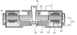
図1は、本発明の第1の実施形態に係るモーターの断面図、図2は、図1のステータコアの斜視図、図3は、本発明の第2の実施形態に係るモーターの断面図、そして、図4は、本発明の第3の実施形態に係るステータのコアとインシュレーターの平面図である。 1 is a cross-sectional view of a motor according to a first embodiment of the present invention, FIG. 2 is a perspective view of a stator core of FIG. 1, and FIG. 3 is a cross-sectional view of a motor according to a second embodiment of the present invention. FIG. 4 is a plan view of the stator core and insulator according to the third embodiment of the present invention.
図1に示すように、本発明によるEPSモーターは、ハウジング10、ステータ20、及びローター30を含む。
As shown in FIG. 1, the EPS motor according to the present invention includes a
ハウジング10は、上部ハウジング11と下部ハウジング12とで構成されており、これらの結合で形成される内部空間部には、複数のコイルが巻線されるステータ20が設けられる。
The
ステータ20は、ステータコア21、インシュレーター22、及びコイル23で構成することができる。
The
ステータコア21は、金属材質のブロックで設けられてもよく、薄いプレート材質のコア部材が複数枚積層されて構成されてもよい。前記ステータコア21には、前記ローター30に向き合う面に向かって複数個の歯が突設されており、この歯にコイル23が巻線される。
The
インシュレーター22は、前記ステータコア21の上側及び下側に結合されており、前記歯に巻線されるコイル23が、前記ステータコア21と通電しないように絶縁する役割を果たす。インシュレーター22は、樹脂材質で形成されてもよい。
The
ローター30は、前記ステータ20の中央に回転軸31により回転可能に設けられる。前記ローター30は、ローターコアにマグネットが結合されて構成されてもよく、場合によっては、ローターコアとマグネットとが一体に構成されてもよい。前記回転軸31の両端は、ベアリング32によって回転可能に支持されることが好ましい。前記ローター30の上側には、ローター30の位置情報取得のためのセンシングマグネットがプレートに結合されて設けられてもよく、これと類似のローター位置検出手段が設けられてもよい。
The
本発明の特徴は、ハウジング10の内部空間部に設けられるステータ20の共振を防止するための構成にあり、これは、次のような実施形態に分けられる。
A feature of the present invention resides in a configuration for preventing resonance of the
本発明の第1の実施形態によれば、ステータ20は、図1及び図2に示すように、インシュレーター22の介在下、コイル23が巻線された外側をエポキシモールディングのような絶縁性部材100でコーティングして、ステータ20の外部が前記絶縁性部材100で包み込まれるように構成し、図1のように、前記ハウジング10内部のステータ20の設置空間を、前記絶縁性部材100で包み込まれたステータ20が満ちるように構成してもよい。
According to the first embodiment of the present invention, as shown in FIGS. 1 and 2, the
このような構成によれば、ステータ20に絶縁性部材100がコーティングされてステータ20の固有振動数が変化するため、共振による振動を減らすことができ、ステータ20を包み込んでいる絶縁性部材100が上部及び下部ハウジング11、12の内側面と面接触することによって、ローター30とステータ20の電磁気力によって発生できる振動が前記絶縁性部材100と上部及び下部ハウジング11、12によって吸収できる。したがって、モーターの作動中に発生できるステータ20の振動を抑制し、モーターの静粛性と作動信頼性を向上させることができる。
According to such a configuration, since the insulating
図3は、本発明の第2の実施形態に係るモーターの断面図を示す図である。図示しているように、前記の第1の実施形態と大部分の構成は同様であるが、前記インシュレーター22と下部ハウジング12の形態を一部変更して、振動防止ユニット200を構成したことに特徴がある。
FIG. 3 is a cross-sectional view of a motor according to the second embodiment of the present invention. As shown in the figure, the configuration of the
つまり、前記インシュレーター22の前記上部ハウジング11に向き合う面は、前記上部ハウジング11の内周面と面接触できる長さだけ延設される第1加圧リブ210が形成され、前記第1加圧リブ210が前記上部ハウジング11の内周面との全て面接触できるように構成することができる。これと共に、前記下部ハウジング12の前記インシュレーター22に向き合う底面には、前記インシュレーター22を加圧する環状の第2加圧リブ220が突設できる。前記第2加圧リブ220は、図3に示すように、前記歯を包み込んでいるインシュレーター22の底面と対応する位置に形成されてもよいが、これに限定するものではなく、前記インシュレーター22を底面で支持できる位置であれば、どのような所にも形成可能である。
That is, the surface of the
このような構成によれば、前記インシュレーター22の上部面は、第1加圧リブ210で前記上部ハウジング11と面接触し、インシュレーター22の下部面は第2加圧リブ220で前記下部ハウジング12と面接触して、前記ステータコア21の固有振動数が変化するため、共振による振動を減らすことができる。また、上部及び下部ハウジング11、12の内側面とインシュレーター22とが面接触することによって、ローター30とステータ20の電磁気力によって発生できる振動が前記絶縁性部材100と上部及び下部ハウジング11、12によって吸収できる。したがって、モーターの作動中に発生できるステータ20の振動を抑制し、モーターの静粛性と作動信頼性を向上させることができる。
According to such a configuration, the upper surface of the
図4は、本発明の第4の実施形態に係るインシュレーター22が設けられたステータコア21を示す平面図である。
FIG. 4 is a plan view showing a
図示しているように、インシュレーター22は、ステータコア21に形成された歯を包み込むように構成され、歯にコイル23が巻線されるとき、ステータコア21とショートしないようにする。しかし、一般に、歯とローター30が互いに向き合う面は、ステータコア21の歯が露出されており、それぞれの歯は所定間隔離隔されるが、本発明の第4の実施形態の場合には、これら歯が離隔した状態はそのまま維持しながら、前記歯を包み込んでいるインシュレーター22の歯部分が互いに接触された接触部300を形成することができる。
As shown in the figure, the
このような構成によれば、それぞれの歯を包み込むインシュレーター22が接触部300で互に連結されるため、結果的に、ステータコア21から発生する振動を前記インシュレーター22の接触部300が吸収する役割を果たすことができ、モーターの作動中に発生できる振動を低減することができる。
According to such a configuration, since the
以上で、本発明は、実施形態及び添付図面に基づいて詳細に説明された。しかしながら、以上の実施形態及び図面により本発明の範囲が限定されることはなく、本発明の範囲は、別途提出の特許請求の範囲に記載された内容によってのみ制限される。 The present invention has been described in detail above based on the embodiments and the accompanying drawings. However, the scope of the present invention is not limited by the above embodiments and drawings, and the scope of the present invention is limited only by the contents described in the appended claims.
10 ハウジング
11 上部ハウジング
12 下部ハウジング
20 ステータ
21 ステータコア
22 インシュレーター
23 コイル
30 ローター
31 回転軸
32 ベアリング
DESCRIPTION OF
Claims (9)
前記ハウジングの内側に設けられるステータと、
前記ステータの内側に設けられ、回転軸と結合するローターと、
前記ステータと前記ハウジングとの間に設けられる振動防止ユニットと、を含み、
前記ステータは、複数個の歯を有するステータコアと、前記ステータコアに巻線されるコイルと、前記ステータコアの上側及び下側に設けられるインシュレーターと、を含み、
前記ハウジングは上部ハウジング及び前記上部ハウジングと離隔された下部ハウジングを含み、
前記振動防止ユニットは、前記インシュレーターの前記上部ハウジングと向き合う面から前記上部ハウジングに向かって上側に延設された一対の第1加圧リブと、前記インシュレーターと向き合う前記下部ハウジングの底面から前記インシュレーターに向かってリング状に突出形成された第2加圧リブと、を含み、
前記ステータコアの上面を基準に前記第1加圧リブの高さは前記コイルの高さより高く、
前記第2加圧リブは前記歯を包み込む前記インシュレーターの下面と向き合う位置に配置され、
前記インシュレーターの上面は、第1加圧リブを介して前記上部ハウジングの内周面と接触し、前記インシュレーターの下面は、第2加圧リブを介して前記下部ハウジングと接触し、前記ステータの動きを規制して振動を防止することを特徴とするモーター。 A housing;
A stator provided inside the housing;
A rotor provided inside the stator and coupled to a rotation shaft;
Anda vibration prevention unit provided between the housing and the scan stator,
The stator includes a stator core having a plurality of teeth, a coil is wound on the stator core, the upper and insulator provided on the lower side of the front Symbol stator core, and
The housing includes an upper housing and a lower housing spaced apart from the upper housing ;
The anti-vibration unit includes a pair of first pressure rib that extends upward from a surface facing said upper housing of said insulator toward the upper housing, the insulator from the bottom surface of the lower housing facing the said insulator toward viewed contains a second pressure rib protruding in a ring shape, and
The height of the first pressure rib with respect to the upper surface of the stator core is higher than the height of the coil,
The second pressure rib is disposed at a position facing the lower surface of the insulator that wraps the teeth,
The upper surface of the insulator is in contact with the inner peripheral surface of the upper housing through a first pressure rib, and the lower surface of the insulator is in contact with the lower housing through a second pressure rib, and the movement of the stator A motor characterized by regulating vibration to prevent vibration .
前記接触部は隣接する接触部と接触することを特徴とする請求項1乃至5のうちいずれか一つに記載のモーター。 The insulator includes a contact portion that wraps around a tooth end of the stator core;
Motor according to any one of claims 1 to 5 wherein the contact portion is characterized by contacting the contact portion adjacent.
Applications Claiming Priority (2)
| Application Number | Priority Date | Filing Date | Title |
|---|---|---|---|
| KR10-2012-0064172 | 2012-06-15 | ||
| KR1020120064172A KR101930333B1 (en) | 2012-06-15 | 2012-06-15 | Motor |
Publications (3)
| Publication Number | Publication Date |
|---|---|
| JP2014003885A JP2014003885A (en) | 2014-01-09 |
| JP2014003885A5 JP2014003885A5 (en) | 2016-07-14 |
| JP6243635B2 true JP6243635B2 (en) | 2017-12-06 |
Family
ID=48577621
Family Applications (1)
| Application Number | Title | Priority Date | Filing Date |
|---|---|---|---|
| JP2013122561A Active JP6243635B2 (en) | 2012-06-15 | 2013-06-11 | motor |
Country Status (5)
| Country | Link |
|---|---|
| US (1) | US20130334909A1 (en) |
| EP (1) | EP2675042B1 (en) |
| JP (1) | JP6243635B2 (en) |
| KR (1) | KR101930333B1 (en) |
| CN (1) | CN103516120B (en) |
Families Citing this family (2)
| Publication number | Priority date | Publication date | Assignee | Title |
|---|---|---|---|---|
| JP6395751B2 (en) * | 2016-03-30 | 2018-09-26 | 三菱電機株式会社 | Rotating electric machine and electric power steering apparatus |
| KR102191128B1 (en) * | 2019-04-05 | 2020-12-16 | 엘지전자 주식회사 | Motor part and electric compressor including the same |
Family Cites Families (23)
| Publication number | Priority date | Publication date | Assignee | Title |
|---|---|---|---|---|
| US2668925A (en) * | 1949-04-05 | 1954-02-09 | Kearfott Company Inc | Electric machine construction |
| US3465182A (en) * | 1967-04-12 | 1969-09-02 | Gen Electric | Motor vibration suppression mounting system |
| JPH01138936A (en) * | 1988-08-27 | 1989-05-31 | Shibaura Eng Works Co Ltd | Manufacture of induction motor stator |
| JPH0515101A (en) * | 1991-06-28 | 1993-01-22 | Asmo Co Ltd | Resin-molded type rotating electric machine |
| JPH06261528A (en) * | 1993-03-08 | 1994-09-16 | Matsushita Electric Ind Co Ltd | Stepping motor |
| AU1931099A (en) * | 1997-12-23 | 1999-07-12 | Emerson Electric Co. | Electromagnetic device having encapsulated construction and precise positioning of bearing and shaft axes |
| JP2000188841A (en) * | 1998-12-21 | 2000-07-04 | Matsushita Electric Ind Co Ltd | Dc brushless motor |
| JP2000217302A (en) * | 1999-01-19 | 2000-08-04 | Nippon Densan Corp | Motor |
| JP4076714B2 (en) * | 2000-09-04 | 2008-04-16 | 三菱電機株式会社 | Motor stator, motor, DC brushless motor, and air conditioner |
| US7036207B2 (en) * | 2001-03-02 | 2006-05-02 | Encap Motor Corporation | Stator assembly made from a plurality of toroidal core segments and motor using same |
| JP3882721B2 (en) * | 2002-09-13 | 2007-02-21 | 日産自動車株式会社 | Cooling structure for rotating electrical machine and method for manufacturing the same |
| JP3987413B2 (en) * | 2002-10-22 | 2007-10-10 | ミネベア株式会社 | motor |
| JP4627701B2 (en) * | 2005-08-10 | 2011-02-09 | 日立オートモティブシステムズ株式会社 | Rotating electric machine |
| TWI280322B (en) * | 2005-12-23 | 2007-05-01 | Delta Electronics Inc | Fan and motor thereof |
| JP2007189812A (en) * | 2006-01-12 | 2007-07-26 | Toyota Motor Corp | Inner rotor type brushless motor |
| JP2007318924A (en) * | 2006-05-26 | 2007-12-06 | Sanden Corp | Stator fixing structure of electric motor |
| JP4680875B2 (en) * | 2006-12-11 | 2011-05-11 | 三菱電機株式会社 | Stator core manufacturing method |
| JP2009232658A (en) * | 2008-03-25 | 2009-10-08 | Asmo Co Ltd | Rotating electric machine |
| JP5347380B2 (en) * | 2008-08-28 | 2013-11-20 | アイシン精機株式会社 | Oil cooling structure of motor |
| TWI373903B (en) * | 2008-09-23 | 2012-10-01 | Sunonwealth Electr Mach Ind Co | Inner-rotor type fan |
| CN101771298A (en) * | 2008-12-26 | 2010-07-07 | 三洋电机株式会社 | Molded motor and electric vehicle |
| JP5630650B2 (en) * | 2010-01-12 | 2014-11-26 | 日本電産株式会社 | Motor and motor manufacturing method |
| JP5216038B2 (en) * | 2010-03-25 | 2013-06-19 | 株式会社日立製作所 | Rotating motor |
-
2012
- 2012-06-15 KR KR1020120064172A patent/KR101930333B1/en active IP Right Grant
-
2013
- 2013-06-11 EP EP13171563.3A patent/EP2675042B1/en active Active
- 2013-06-11 JP JP2013122561A patent/JP6243635B2/en active Active
- 2013-06-13 US US13/917,076 patent/US20130334909A1/en not_active Abandoned
- 2013-06-14 CN CN201310234850.3A patent/CN103516120B/en active Active
Also Published As
| Publication number | Publication date |
|---|---|
| EP2675042A3 (en) | 2017-05-17 |
| EP2675042A2 (en) | 2013-12-18 |
| EP2675042B1 (en) | 2021-08-04 |
| CN103516120A (en) | 2014-01-15 |
| KR20130141076A (en) | 2013-12-26 |
| CN103516120B (en) | 2018-09-04 |
| KR101930333B1 (en) | 2018-12-18 |
| US20130334909A1 (en) | 2013-12-19 |
| JP2014003885A (en) | 2014-01-09 |
Similar Documents
| Publication | Publication Date | Title |
|---|---|---|
| JP5522009B2 (en) | Electric compressor | |
| JP5850263B2 (en) | Drive device | |
| JP5865767B2 (en) | In-vehicle rotating electrical machine and electric power steering device | |
| US8791610B2 (en) | Anti-separating structure of sensing magnet for EPS motor | |
| JP6001167B2 (en) | Magnet scattering prevention and holding structure for rotating electrical machines | |
| US9559563B2 (en) | Motor | |
| JP6243635B2 (en) | motor | |
| JP6870989B2 (en) | Rotor and electric motor | |
| JP5826536B2 (en) | motor | |
| US20130134824A1 (en) | Stator core | |
| KR102145758B1 (en) | BLDC motor with anti-electric construction | |
| JP2014036506A (en) | Armature and rotary electric machine using the same | |
| JP4051543B2 (en) | Bracket and stepping motor | |
| KR20170045998A (en) | Rotor assembly and motor having the same | |
| KR101799104B1 (en) | Motor | |
| KR102587578B1 (en) | Stator and motor having the same | |
| KR102477861B1 (en) | Motor and appartus for steering | |
| JP2007124828A (en) | Rotating electric machine | |
| JP2021027717A (en) | Rotor, motor, and brushless wiper motor | |
| KR102311773B1 (en) | coil insulation securing structure for motor stator | |
| KR102488442B1 (en) | Motor apparatus | |
| KR200464575Y1 (en) | Stator for a motor | |
| JP6227381B2 (en) | Brushless motor | |
| JP5911756B2 (en) | Rotating electric machine | |
| JP2017225239A (en) | Motor housing, motor, and motor with reduction gear |
Legal Events
| Date | Code | Title | Description |
|---|---|---|---|
| A521 | Request for written amendment filed |
Free format text: JAPANESE INTERMEDIATE CODE: A523 Effective date: 20160531 |
|
| A621 | Written request for application examination |
Free format text: JAPANESE INTERMEDIATE CODE: A621 Effective date: 20160531 |
|
| A977 | Report on retrieval |
Free format text: JAPANESE INTERMEDIATE CODE: A971007 Effective date: 20170130 |
|
| A131 | Notification of reasons for refusal |
Free format text: JAPANESE INTERMEDIATE CODE: A131 Effective date: 20170214 |
|
| A521 | Request for written amendment filed |
Free format text: JAPANESE INTERMEDIATE CODE: A523 Effective date: 20170512 |
|
| A131 | Notification of reasons for refusal |
Free format text: JAPANESE INTERMEDIATE CODE: A131 Effective date: 20170704 |
|
| A521 | Request for written amendment filed |
Free format text: JAPANESE INTERMEDIATE CODE: A523 Effective date: 20171002 |
|
| TRDD | Decision of grant or rejection written | ||
| A01 | Written decision to grant a patent or to grant a registration (utility model) |
Free format text: JAPANESE INTERMEDIATE CODE: A01 Effective date: 20171017 |
|
| A61 | First payment of annual fees (during grant procedure) |
Free format text: JAPANESE INTERMEDIATE CODE: A61 Effective date: 20171110 |
|
| R150 | Certificate of patent or registration of utility model |
Ref document number: 6243635 Country of ref document: JP Free format text: JAPANESE INTERMEDIATE CODE: R150 |
|
| R250 | Receipt of annual fees |
Free format text: JAPANESE INTERMEDIATE CODE: R250 |
|
| R250 | Receipt of annual fees |
Free format text: JAPANESE INTERMEDIATE CODE: R250 |
|
| R250 | Receipt of annual fees |
Free format text: JAPANESE INTERMEDIATE CODE: R250 |
|
| R250 | Receipt of annual fees |
Free format text: JAPANESE INTERMEDIATE CODE: R250 |