JP6243128B2 - Crane control device, crane, crane control method, and software for executing the control method - Google Patents
Crane control device, crane, crane control method, and software for executing the control method Download PDFInfo
- Publication number
- JP6243128B2 JP6243128B2 JP2013046505A JP2013046505A JP6243128B2 JP 6243128 B2 JP6243128 B2 JP 6243128B2 JP 2013046505 A JP2013046505 A JP 2013046505A JP 2013046505 A JP2013046505 A JP 2013046505A JP 6243128 B2 JP6243128 B2 JP 6243128B2
- Authority
- JP
- Japan
- Prior art keywords
- wire rope
- hoisting device
- crane
- function
- control device
- Prior art date
- Legal status (The legal status is an assumption and is not a legal conclusion. Google has not performed a legal analysis and makes no representation as to the accuracy of the status listed.)
- Active
Links
- 238000000034 method Methods 0.000 title claims description 19
- 230000001133 acceleration Effects 0.000 claims description 67
- 239000000725 suspension Substances 0.000 claims description 49
- 230000036461 convulsion Effects 0.000 claims description 30
- 238000005457 optimization Methods 0.000 claims description 30
- 238000004364 calculation method Methods 0.000 claims description 15
- 238000005259 measurement Methods 0.000 claims description 15
- 230000003796 beauty Effects 0.000 claims 1
- 230000006870 function Effects 0.000 description 108
- 230000008859 change Effects 0.000 description 7
- 230000003068 static effect Effects 0.000 description 7
- 230000010354 integration Effects 0.000 description 6
- 238000012546 transfer Methods 0.000 description 6
- 238000004804 winding Methods 0.000 description 6
- 238000001514 detection method Methods 0.000 description 5
- 238000010586 diagram Methods 0.000 description 5
- 238000006073 displacement reaction Methods 0.000 description 5
- 230000014509 gene expression Effects 0.000 description 5
- 230000005484 gravity Effects 0.000 description 5
- 230000006641 stabilisation Effects 0.000 description 5
- 238000011105 stabilization Methods 0.000 description 5
- XLYOFNOQVPJJNP-UHFFFAOYSA-N water Substances O XLYOFNOQVPJJNP-UHFFFAOYSA-N 0.000 description 5
- 230000009471 action Effects 0.000 description 4
- 238000011156 evaluation Methods 0.000 description 4
- 230000007704 transition Effects 0.000 description 4
- 238000005381 potential energy Methods 0.000 description 3
- 230000008901 benefit Effects 0.000 description 2
- 238000004422 calculation algorithm Methods 0.000 description 2
- 230000010355 oscillation Effects 0.000 description 2
- 238000004088 simulation Methods 0.000 description 2
- 230000004913 activation Effects 0.000 description 1
- 238000013016 damping Methods 0.000 description 1
- 238000013500 data storage Methods 0.000 description 1
- 238000013461 design Methods 0.000 description 1
- 230000004069 differentiation Effects 0.000 description 1
- 230000000694 effects Effects 0.000 description 1
- 238000002474 experimental method Methods 0.000 description 1
- 238000001914 filtration Methods 0.000 description 1
- 238000009472 formulation Methods 0.000 description 1
- 238000012423 maintenance Methods 0.000 description 1
- 239000011159 matrix material Substances 0.000 description 1
- 230000007246 mechanism Effects 0.000 description 1
- 239000000203 mixture Substances 0.000 description 1
- 230000008569 process Effects 0.000 description 1
- 238000012545 processing Methods 0.000 description 1
- 230000004044 response Effects 0.000 description 1
- 230000000452 restraining effect Effects 0.000 description 1
Images


Classifications
-
- B—PERFORMING OPERATIONS; TRANSPORTING
- B66—HOISTING; LIFTING; HAULING
- B66C—CRANES; LOAD-ENGAGING ELEMENTS OR DEVICES FOR CRANES, CAPSTANS, WINCHES, OR TACKLES
- B66C13/00—Other constructional features or details
- B66C13/04—Auxiliary devices for controlling movements of suspended loads, or preventing cable slack
-
- B—PERFORMING OPERATIONS; TRANSPORTING
- B66—HOISTING; LIFTING; HAULING
- B66C—CRANES; LOAD-ENGAGING ELEMENTS OR DEVICES FOR CRANES, CAPSTANS, WINCHES, OR TACKLES
- B66C13/00—Other constructional features or details
- B66C13/02—Devices for facilitating retrieval of floating objects, e.g. for recovering crafts from water
-
- B—PERFORMING OPERATIONS; TRANSPORTING
- B66—HOISTING; LIFTING; HAULING
- B66C—CRANES; LOAD-ENGAGING ELEMENTS OR DEVICES FOR CRANES, CAPSTANS, WINCHES, OR TACKLES
- B66C13/00—Other constructional features or details
- B66C13/04—Auxiliary devices for controlling movements of suspended loads, or preventing cable slack
- B66C13/08—Auxiliary devices for controlling movements of suspended loads, or preventing cable slack for depositing loads in desired attitudes or positions
- B66C13/085—Auxiliary devices for controlling movements of suspended loads, or preventing cable slack for depositing loads in desired attitudes or positions electrical
-
- B—PERFORMING OPERATIONS; TRANSPORTING
- B66—HOISTING; LIFTING; HAULING
- B66C—CRANES; LOAD-ENGAGING ELEMENTS OR DEVICES FOR CRANES, CAPSTANS, WINCHES, OR TACKLES
- B66C13/00—Other constructional features or details
- B66C13/18—Control systems or devices
-
- B—PERFORMING OPERATIONS; TRANSPORTING
- B66—HOISTING; LIFTING; HAULING
- B66C—CRANES; LOAD-ENGAGING ELEMENTS OR DEVICES FOR CRANES, CAPSTANS, WINCHES, OR TACKLES
- B66C23/00—Cranes comprising essentially a beam, boom, or triangular structure acting as a cantilever and mounted for translatory of swinging movements in vertical or horizontal planes or a combination of such movements, e.g. jib-cranes, derricks, tower cranes
- B66C23/18—Cranes comprising essentially a beam, boom, or triangular structure acting as a cantilever and mounted for translatory of swinging movements in vertical or horizontal planes or a combination of such movements, e.g. jib-cranes, derricks, tower cranes specially adapted for use in particular purposes
- B66C23/36—Cranes comprising essentially a beam, boom, or triangular structure acting as a cantilever and mounted for translatory of swinging movements in vertical or horizontal planes or a combination of such movements, e.g. jib-cranes, derricks, tower cranes specially adapted for use in particular purposes mounted on road or rail vehicles; Manually-movable jib-cranes for use in workshops; Floating cranes
- B66C23/52—Floating cranes
Description
本発明は、ワイヤロープに荷物を掛けて吊り上げるための巻上装置を有するクレーンのためのクレーン制御装置に関する。このクレーン制御装置は、上下揺れに起因してワイヤロープ吊下箇所及び/又は荷置箇所に生じる揺動を、少なくとも部分的に補償するように巻上装置を作動させる上下揺れ補償機能を備えている。 The present invention relates to a crane control device for a crane having a hoisting device for hanging a load on a wire rope and lifting it. This crane control device is provided with an up / down compensation function for operating the hoisting device so as to at least partially compensate for the oscillation that occurs at the wire rope suspension location and / or loading location due to the vertical oscillation. Yes.
上記の様なクレーン制御装置は、例えば特許文献1によって公知である。このクレーン制御装置には、計測された目下の上下揺れと、上下揺れの物理モデルを参照し、ワイヤロープの以後の揺動を予測するための予測装置が備えられており、ワイヤロープ吊下箇所の予測された揺動は、荷物のための経路制御装置によって少なくとも部分的に補償される。 A crane control device such as that described above is known, for example, from US Pat. This crane control device is equipped with a prediction device for predicting subsequent swing of the wire rope by referring to the measured physical model of the current vertical swing and vertical swing. This predicted swing is at least partially compensated by the routing device for the load.
特許文献1に記載された発明に従うと、巻上装置を作動させるために、油圧によって動作するウインチと、ワイヤロープに吊した荷物との両者について動的挙動を記述する物理モデルを生成し、モデルに対して逆解析を用いることによってシーケンス制御ユニットを生成する。状態制御を実現するために、荷物の未知なる状態変数が、オブザーバ(状態推定器)を介して力の測定値から推定される。
According to the invention described in
本発明の課題は改良されたクレーン制御装置を提供することにある。 An object of the present invention is to provide an improved crane control device.
本発明に従うと、上記課題は請求項1に係るクレーン制御装置の第1の態様と、請求項5に係るクレーン制御装置の第2の態様によって解決される。
According to this invention, the said subject is solved by the 1st aspect of the crane control apparatus which concerns on
第1の態様では、本発明はワイヤロープに掛けた荷物を吊り上げるための巻上装置を有するクレーンのためのクレーン制御装置を開示している。クレーン制御装置には、上下揺れに起因してワイヤロープ吊下箇所及び/又は荷置箇所に生じる揺動を、少なくとも部分的に補償するように巻上装置を作動させる能動的上下揺れ補償機能が備えられる。本発明によると、巻上装置の動作を計算する際に、上下揺れ補償機能は巻上装置における少なくとも1つ以上の拘束量を考慮に入れる。巻上装置の拘束量を考慮することによって、上下揺れ補償機能によって計算された制御命令に、巻上装置が実際に従い得ること、及び/又は巻上装置若しくはクレーンが動作によって損傷を受けないことが保証される。 In a first aspect, the present invention discloses a crane control device for a crane having a hoisting device for lifting a load hung on a wire rope. The crane controller has an active up / down compensation function that activates the hoisting device so as to at least partially compensate for the swings that occur at the wire rope suspension and / or loading location due to ups and downs. Provided. According to the present invention, when calculating the operation of the hoisting device, the vertical compensation function takes into account at least one constraint amount in the hoisting device. By taking into account the amount of restraint of the hoisting device, the hoisting device can actually follow the control commands calculated by the up and down compensation function and / or the hoisting device or crane may not be damaged by operation. Guaranteed.
本発明によると、上下揺れ補償機能は最大許容躍度(加加速度)を考慮することができる。考慮を行うことで、巻上装置又はクレーン構造が、上下揺れ補償機能により生じる巻上装置の動作によって損傷を受けないことが保証される。躍度に関しては、最大許容値(拘束量)が設定されるに留まらず、その上連続的な振る舞いを条件とすることもある。 According to the present invention, the up / down compensation function can take into account the maximum allowable jerk (jerk). By taking into account, it is ensured that the hoisting device or crane structure is not damaged by the hoisting device operation caused by the up and down compensation function. Regarding jerk, not only the maximum allowable value (constraint amount) is set, but also continuous behavior may be a condition.
及び/又は、上下揺れ補償機能は最大許容動力を考慮することができる。 And / or the vertical compensation function can take into account the maximum allowable power.
及び/又は、上下揺れ補償機能は最大許容加速度を考慮することができる。そうした最大許容加速度は、例えば巻上装置の最大駆動動力、及び/又は既に繰り出されたワイヤロープの長さ、及び繰り出されたワイヤロープに起因して巻上装置に作用する重力、及び/又は吊り上げられる荷重に起因して巻上装置に作用する重力に由来する。 And / or the up / down compensation function can take into account the maximum allowable acceleration. Such maximum permissible accelerations are, for example, the maximum drive power of the hoisting device and / or the length of the wire rope that has already been unwound and the gravity acting on the hoisting device due to the unwound wire rope and / or lifting. Due to the gravity acting on the hoisting device due to the applied load.
その上、及び/又は、上下揺れ補償機能は最大許容速度を考慮することができる。上下揺れ補償機能で考慮される最大許容速度も、最大許容加速度について既に述べられたような原因に由来する。 In addition and / or the up / down compensation function can take into account the maximum permissible speed. The maximum permissible speed considered in the vertical shake compensation function also originates from the causes already described for the maximum permissible acceleration.
その上クレーン制御装置は、巻上装置における1つ以上の拘束量を計算するための計算機能を備えることができる。この目的のため、計算機能は特にセンサーデータ及び/又は作動信号を評価することができる。計算機能を用いることによって、巻上装置が目下利用できる拘束量を、それぞれ上下揺れ補償機能へと伝えることができる。 Moreover, the crane control device can have a calculation function for calculating one or more restraints in the hoisting device. For this purpose, the calculation function can in particular evaluate sensor data and / or actuation signals. By using the calculation function, the amount of restraint that can be used by the hoisting device can be transmitted to the up / down compensation function.
特に、巻上装置の拘束量は、吊上作業中に変化し得る。本発明に係る上下揺れ補償機能によって、拘束量の変化を考慮することができる。 In particular, the amount of restraint of the hoisting device can change during the hoisting operation. With the vertical shake compensation function according to the present invention, it is possible to take into account changes in the amount of restraint.
計算機能は、巻上装置が目下利用できる1つ以上の運動学的拘束量、特に巻上装置の最大許容動力及び/又は最大許容速度及び/又は最大許容加速度のそれぞれを、厳密に計算することができる。計算機能は、繰り出されたワイヤロープの長さ及び/又はワイヤロープの張力及び/又は巻上装置を駆動するために利用できる動力を考慮すると有利である。 The calculation function strictly calculates one or more kinematic constraints currently available to the hoisting device, in particular each of the maximum permissible power and / or maximum permissible speed and / or maximum permissible acceleration of the hoisting device. Can do. The calculation function is advantageous in view of the length of the drawn wire rope and / or the tension of the wire rope and / or the power available to drive the hoisting device.
本発明によると、その駆動部がアキュムレータに接続された巻上装置を作動させるために、クレーン制御装置を用いることができる。アキュムレータに蓄積されたエネルギー量は、装置を駆動させるために利用できる動力に影響を及ぼす。アキュムレータに蓄えられるエネルギー量、又はそれに影響を受けた巻上装置を駆動するために利用できる動力は、本発明に係る計算機能で考慮されると有利である。 According to the present invention, a crane control device can be used to operate a hoisting device whose drive is connected to an accumulator. The amount of energy stored in the accumulator affects the power available to drive the device. The amount of energy stored in the accumulator, or the power available to drive the hoisting device affected by it, is advantageously taken into account in the calculation function according to the invention.
特に、本発明に係る巻上装置は油圧によって動作可能であって、巻上装置に備えられた巻上用ウインチを駆動させるための油圧回路に、油圧アキュムレータが備えられる。 In particular, the hoisting device according to the present invention can be operated by hydraulic pressure, and a hydraulic accumulator is provided in a hydraulic circuit for driving a hoisting winch provided in the hoisting device.
あるいは、電気駆動方式を用いることも可能である。電気駆動方式を用いた場合も、同様にアキュムレータに接続することができる。 Alternatively, an electric drive system can be used. Similarly, when an electric drive system is used, it can be connected to an accumulator.
ワイヤロープ吊下箇所及び/又は荷置箇所の動作予測を参照した上で、巻上装置の拘束量を考慮することによって軌道を決定する経路設定モジュールが、クレーン制御装置にさらに備えられると有利である。本発明によると、軌道を設定する際には、特に動力及び/又は速度及び/又は加速度及び/又は躍度に関する駆動部の拘束量を積極的に考慮することができる。決定された軌道は、特に巻上装置の位置及び/又は速度及び/又は加速度についての軌道とすることができる。 It is advantageous if the crane control device is further provided with a path setting module that determines the trajectory by considering the amount of restraint of the hoisting device after referring to the motion prediction of the wire rope hanging point and / or the loading point. is there. According to the present invention, when the trajectory is set, it is possible to positively consider the restraint amount of the drive unit particularly regarding power and / or speed and / or acceleration and / or jerk. The determined trajectory may in particular be a trajectory for the position and / or speed and / or acceleration of the hoisting device.
経路設定モジュールには、ワイヤロープ吊下箇所及び/又は荷置箇所の動作予測を参照した上で、巻上装置の拘束量を考慮することによって軌道を決定する最適化機能が備えられると有利である。決定された軌道は、ワイヤロープ吊下箇所の揺動に起因して荷物に生じる残余動作、及び又は荷置箇所の揺動に起因して荷物と荷置箇所との間に生じる相対移動を最小化する。本発明によると、最適制御問題では、駆動部における1つ以上の拘束量を考慮することができる。特に、最適制御問題では、動力、速度、加速度、及び/又は躍度に関する駆動部の拘束量を考慮に入れる。 It is advantageous if the route setting module is equipped with an optimization function that determines the trajectory by taking into account the amount of restraint of the hoisting device after referring to the motion prediction of the wire rope suspension point and / or loading point. is there. The determined trajectory minimizes the residual movement that occurs in the load due to swinging of the wire rope suspension location and / or the relative movement that occurs between the load and loading location due to swinging of the loading location. Turn into. According to the present invention, the optimal control problem can take into account one or more constraints on the drive. In particular, the optimal control problem takes into account the drive constraints on power, speed, acceleration, and / or jerk.
最適化機能は、ワイヤロープ吊下箇所及び/又は荷置箇所の鉛直座標及び/又は鉛直速度の予測値を参照して最適経路を計算する。計算の際に運動学的拘束量を考慮することによって、この最適経路は荷物の残余動作及び/又は荷物の相対移動を最小化できると有利である。 The optimization function calculates the optimum route with reference to the predicted value of the vertical coordinate and / or the vertical velocity of the wire rope suspension point and / or loading point. Advantageously, by taking into account the kinematic constraints in the calculation, this optimal path can minimize the residual movement of the load and / or the relative movement of the load.
第2の態様では、本発明にはワイヤロープに荷物を掛けて吊り上げるための巻上装置を有するクレーン制御装置が備えられる。クレーン制御装置には、上下揺れに起因してワイヤロープ吊下箇所及び/又は荷置箇所に生じる揺動を、少なくとも部分的に補償するように巻上装置を作動させる能動的上下揺れ補償機能が備えられる。本発明によると、上下揺れ補償機能には、ワイヤロープ吊下箇所及び/又は荷置箇所の動作予測を参照して、巻上装置の位置及び/又は速度及び/又は加速度の軌道を計算する経路設定モジュールが含まれる。この軌道は、サブシーケンス制御のための設定値として巻上装置に取り入れられる。上下揺れ補償機能がこうした構造をとることによって、巻上装置の動作制御が、特に安定で且つ容易に実現できるものとなる。特に、多大な労力を費やして、荷物の未知なる位置を推定する必要は最早ない。本発明によると、巻上装置の制御装置は、測定値を巻上用ウインチの位置及び/又は速度へとフィードバックすることができる。それゆえ、経路設定モジュールは巻上用ウインチの位置及び/又は速度を設定値として指定し、指定された設定値は、サブシーケンス制御装置において実際の値と調和される。 In a second aspect, the present invention includes a crane control device having a hoisting device for hanging a load on a wire rope and lifting it. The crane controller has an active up / down compensation function that activates the hoisting device so as to at least partially compensate for the swings that occur at the wire rope suspension and / or loading location due to ups and downs. Provided. According to the present invention, the up / down compensation function has a path for calculating the trajectory of the position and / or speed and / or acceleration of the hoisting device with reference to the motion prediction of the wire rope hanging part and / or the loading part. Includes configuration module. This trajectory is taken into the hoisting device as a set value for subsequence control. When the vertical compensation function has such a structure, the operation control of the hoisting device can be realized particularly stably and easily. In particular, it is no longer necessary to spend an enormous amount of effort to estimate the unknown position of the luggage. According to the invention, the control device of the hoisting device can feed back the measured value to the position and / or speed of the hoisting winch. Therefore, the path setting module specifies the position and / or speed of the hoisting winch as the set value, and the specified set value is matched with the actual value in the sub-sequence control device.
その上、巻上装置に備えられた上記制御装置は、フィードフォワード制御機能を用いて巻上用ウインチの駆動部の動的挙動を考慮に入れることができる。特に、フィードフォワード制御機能は、巻上用ウインチの駆動部の動的挙動を記述する物理モデルを逆解析した結果に準拠するように作動させることができる。特に、巻上用ウインチには、油圧によって動作する巻上用ウインチを用いることができる。 In addition, the control device provided in the hoisting device can take into account the dynamic behavior of the hoisting winch drive using the feedforward control function. In particular, the feed-forward control function can be operated to comply with the result of inverse analysis of a physical model describing the dynamic behavior of the drive unit of the hoisting winch. In particular, a hoisting winch that operates by hydraulic pressure can be used as the hoisting winch.
本発明の第1の態様と第2の態様は、本願によってそれぞれ独立して請求され、且つ他の態様を用いずとも単独で実施可能である。 The first and second aspects of the present invention are each independently claimed by the present application and can be practiced alone without using other aspects.
しかしながら、特に好ましくは、本発明に係る2つの態様は互いに組み合わされる。特に、本発明の第2の態様に係る経路設定モジュールは、軌道を決定する際に巻上装置における1つ以上の許容値を考慮に入れることができる。 However, particularly preferably, the two aspects according to the invention are combined with each other. In particular, the path setting module according to the second aspect of the present invention can take into account one or more tolerances in the hoisting device when determining the trajectory.
その上、本発明に係るクレーン制御装置は、オペレータによる入力を参照して巻上装置を作動させるオペレータ制御機能を有することができる。 Moreover, the crane control device according to the present invention can have an operator control function for operating the hoisting device with reference to an input by the operator.
さらに上記制御装置には、上下揺れ補償機能及びオペレータ制御機能のための軌道を互いに独立して計算するための、2つの独立した経路設定モジュールが備えられると有利である。特に、これら軌道を巻上装置の位置及び/又は速度及び/又は加速度のための軌道とすることができる。 Furthermore, it is advantageous if the control device is provided with two independent path setting modules for calculating the trajectories for the up / down compensation function and the operator control function independently of each other. In particular, these trajectories can be trajectories for the position and / or speed and / or acceleration of the hoisting device.
その上、2つの独立した経路設定モジュールによって指定される軌道を加算して、巻上装置のための制御及び/又は調整のための設定値として供給することができる。 In addition, the trajectories specified by two independent path setting modules can be summed and provided as a set value for control and / or adjustment for the hoisting device.
その上、本発明によると、上下揺れ補償機能とオペレータ制御機能との間で、1つ以上の運動学的拘束量を調整自在に配分することができる。この配分調整は、例えば重み係数によって実行可能であり、この係数で重み付けすることによって、巻上装置の最大許容動力及び/又は最大許容速度及び/又は最大許容加速が上下揺れ補償機能とオペレータ制御機能との間で分割される。 In addition, according to the present invention, one or more kinematic constraints can be apportionably distributed between the up / down compensation function and the operator control function. This distribution adjustment can be performed by, for example, a weighting factor. By weighting with this factor, the maximum allowable power and / or the maximum allowable speed and / or the maximum allowable acceleration of the hoisting device can be compensated for the vertical motion compensation and the operator control function. Divided between and.
そのような配分は、巻上装置の拘束量を考慮するように構成された本発明に係る上下揺れ補償機能においては、容易に実施することができる。特に、配分された1つ以上の運動学的拘束量は、巻上装置における拘束量として考慮される。オペレータ制御機能も、駆動部の1つ以上の拘束量、特に最大許容躍度及び/又は最大許容動力及び/又は最大許容加速度及び/又は最大許容速度を考慮に入れると有利である。 Such distribution can be easily implemented in the vertical compensation function according to the present invention configured to take into account the restraint amount of the hoisting device. In particular, the allocated one or more kinematic constraints are considered as constraints in the hoisting device. The operator control function also advantageously takes into account one or more constraints of the drive, in particular the maximum allowable jerk and / or maximum allowable power and / or maximum allowable acceleration and / or maximum allowable speed.
本発明によると、上下揺れ補償機能の最適機能は、巻上装置の制御及び/又は調整に取り入れられる目標軌道を決定できる。特に、上記のように最適化機能は巻上装置の位置及び/又は速度及び/又は加速度の目標軌道を計算できる。この目標軌道は、巻上装置のサブシーケンス制御のための設定値に取り入れられる。最適化機能による最適化は、離散的な予測区間上で実行される。 According to the present invention, the optimal function of the up / down compensation function can determine the target trajectory to be taken into control and / or adjustment of the hoisting device. In particular, as described above, the optimization function can calculate a target trajectory for the position and / or velocity and / or acceleration of the hoisting device. This target trajectory is incorporated into a set value for sub-sequence control of the hoisting device. Optimization by the optimization function is performed on discrete prediction intervals.
本発明によると、ワイヤロープ吊下箇所において更新された動作予測に基づいて、それぞれの時間ステップ毎に最適化を実行できる。 According to the present invention, the optimization can be executed for each time step based on the motion prediction updated at the wire rope suspension point.
本発明によると、それぞれの目標軌道の最初の値を、巻上装置の制御に用いることができる。更新された目標軌道を用いる際にも、同様に最初の値のみを巻上装置の制御に用いることになる。 According to the invention, the initial value of each target trajectory can be used for controlling the hoisting device. Similarly, when the updated target trajectory is used, only the initial value is used for controlling the hoisting device.
本発明によると、最適化機能は制御機能よりも低いスキャンレートで動作できる。このため計算集約的な最適化機能にはより長いスキャンタイムが選択される。他方、そこまで計算集約的ではない制御機能は、スキャンタイムが短くても十分な精度に達する。 According to the present invention, the optimization function can operate at a lower scan rate than the control function. For this reason, a longer scan time is selected for the computationally intensive optimization function. On the other hand, control functions that are not so computationally intensive reach sufficient accuracy even with a short scan time.
その上、有効な解が得られない場合には、最適化機能は緊急軌道設定を利用することができる。このように、有効な解が得られない場合であっても適切な動作が保証されている。 Moreover, if an effective solution is not available, the optimization function can use emergency trajectory settings. Thus, even if a valid solution cannot be obtained, an appropriate operation is guaranteed.
本発明に係るクレーン制御装置は、センサーデータから目下の上下揺れ動作を計測する計測装置を備えることができる。例を挙げると、ジャイロスコープ及び/又は傾斜角センサーを用いることができる。センサーはクレーン又はクレーンが配設されたフロート(浮き船、台船)上、例えばクレーンの土台部及び/又は荷置箇所が配設されたフロート上に取り付けることができる。 The crane control device according to the present invention can include a measuring device that measures the current vertical motion from sensor data. As an example, a gyroscope and / or tilt angle sensor can be used. The sensor can be mounted on a crane or a float (floating ship, trolley) on which the crane is disposed, for example, on a float on which the base and / or loading location of the crane is disposed.
その上、クレーン制御装置は、計測された上下揺れ動作と上下揺れ動作を記述する物理モデルを参照して、ワイヤロープ吊下箇所及び/又は荷置箇所の以後の動作を予測する予測装置を備えることができる。 In addition, the crane control device includes a prediction device that predicts the subsequent operation of the wire rope hanging position and / or the loading position with reference to a physical model that describes the measured vertical movement and vertical movement. be able to.
予測装置に用いられる上下揺れ動作の物理モデルは、特にフロートの動的挙動といった特性には依存しないと有利である。それによって、クレーン及び/又は荷置箇所が配設されるフロートに依存せずに、クレーン制御装置を用いることができる。 It is advantageous if the physical model of the up-and-down motion used in the prediction device does not depend on characteristics such as the dynamic behavior of the float. Thereby, the crane control device can be used without depending on the crane and / or the float on which the loading place is arranged.
予測装置は、測定装置からのデータを用いて、上下揺れ動作において支配的な振動モードを決定できる。特に周波数解析を用いることによって、この決定を行うことができる。 The prediction device can determine the dominant vibration mode in the up and down motion using the data from the measurement device. In particular, this determination can be made by using frequency analysis.
その上、予測装置は、決定された支配的な振動モードを参照して、上下揺れ動作を記述する物理モデルを生成できる。この物理モデルを参照することによって、以後の上下揺れ動作を予測できる。 In addition, the prediction device can generate a physical model describing the up and down motion with reference to the determined dominant vibration mode. By referring to this physical model, it is possible to predict the subsequent up-and-down motion.
予測装置は、測定装置からのデータを参照して物理モデルを連続的にパラメータ化すると有利である。特にオブザーバを用いることが可能であって、オブザーバによって連続的なパラメータ化が施される。特に好ましくは、振動モードの振幅と位相をパラメータ化することができる。 It is advantageous for the prediction device to continuously parameterize the physical model with reference to data from the measurement device. In particular, an observer can be used, and continuous parameterization is performed by the observer. Particularly preferably, the amplitude and phase of the vibration mode can be parameterized.
その上、上下揺れ動作における支配的な振動モードが変化した場合に、物理モデルを更新することができる。 In addition, the physical model can be updated when the dominant vibration mode in the up and down motion changes.
特に好ましくは、予測装置及び測定装置は特許文献1に記載されているように構成されている。
Particularly preferably, the prediction device and the measurement device are configured as described in
さらに本発明に係る制御概念において、ワイヤロープの拡張性のために荷物の動的挙動を無視することができると有利である。動的挙動を無視することよって、より単純な制御構造がもたらされるのは明らかである。 Furthermore, in the control concept according to the invention, it is advantageous if the dynamic behavior of the load can be ignored due to the expandability of the wire rope. Clearly, ignoring dynamic behavior results in a simpler control structure.
その上、本発明には上述のクレーン制御装置を備えたクレーンが含まれる。 Moreover, the present invention includes a crane equipped with the crane control device described above.
特に、クレーンはフロート上に配置しても良く、デッキクレーンであっても良い。あるいは、沖合クレーンや、港湾クレーン、若しくはケーブル式ショベルであっても良い。 In particular, the crane may be placed on a float or a deck crane. Alternatively, an offshore crane, a harbor crane, or a cable excavator may be used.
その上、本発明は、本発明に係るクレーンを備えたフロートを含み、特に本発明に係るクレーンを備えた船を含む。 Moreover, the present invention includes a float with a crane according to the present invention, in particular a ship with a crane according to the present invention.
その上、本発明は、例えば船の上から、水中にある荷物を上げ下ろしするために本発明に係るクレーンや本発明に係るクレーン制御装置を使用すること、及び/又は水中の荷置箇所から荷物を吊り上げ、及び/又は水中の荷置箇所へと荷物を下すために本発明に係るクレーンや本発明に係るクレーン制御装置を使用することを含む。特に本発明は、深海での引き上げ作業や、船への積み上げ、及び/又は積み下ろし作業のために本発明に係るクレーンや本発明に係るクレーン制御装置を使用することを含む。 In addition, the present invention uses the crane according to the present invention and the crane control device according to the present invention to lift and lower the cargo under water, for example from above the ship, and / or the cargo from the underwater loading point. Use of the crane according to the present invention and the crane control device according to the present invention to lift the load and / or lower the load to the underwater loading point. In particular, the present invention includes the use of the crane according to the present invention and the crane control device according to the present invention for a lifting operation in the deep sea, a loading and / or unloading operation on a ship.
その上、本発明はワイヤロープに荷物を掛けて吊り上げるための巻上装置を備えたクレーンを制御する方法を含む。上下揺れ補償機能は、上下揺れに起因してワイヤロープ吊下箇所及び/又は荷置箇所に生じる揺動を、巻上装置を自動的に作動させることによって少なくとも部分的に補償する。本発明の第1の態様によると、上下揺れ補償機能は、巻上装置の動作を計算する際に巻上装置における1つ以上の拘束量を考慮に入れるようにされている。他方、第2の態様によると、上下揺れ補償機能は、ワイヤロープ吊下箇所の動作予測を参照して巻上装置の位置及び/又は速度及び/又は加速度の軌道を計算し、計算された軌道を巻上装置のサブシーケンス制御の設定値に取り入れるようにされている。本発明に係る方法は、上記クレーン制御装置について上述されたことと同様の利点を提供する。 In addition, the present invention includes a method for controlling a crane with a hoisting device for hanging a wire rope and lifting it. The up / down compensation function at least partially compensates for the swing generated at the wire rope suspension point and / or the loading point due to the vertical swing by automatically operating the hoisting device. According to a first aspect of the present invention, the up / down compensation function is adapted to take into account one or more constraints on the hoisting device when calculating the operation of the hoisting device. On the other hand, according to the second aspect, the vertical motion compensation function calculates the trajectory of the position and / or speed and / or acceleration of the hoisting device with reference to the motion prediction of the wire rope suspension point, and the calculated trajectory. Is taken into the setting value of the sub-sequence control of the hoisting device. The method according to the invention provides the same advantages as described above for the crane control device.
加えて、この方法は、上述されたように実行することもできる。特に、本発明に係る2つの態様は、それに係る方法についても互いに組み合わせることができる。 In addition, the method can be performed as described above. In particular, the two aspects according to the invention can also be combined with each other for the method according to it.
さらに好ましくは、本発明に係る発明は、上述されたクレーン制御装置を用いて実行できる。 More preferably, the invention according to the present invention can be implemented using the crane control device described above.
その上、本発明は、本発明に係る方法を実行するためのプログラムコードを備えたソフトウェアを含む。特に、機械読み取り可能なデータ記憶媒体上にソフトウェアを保存できる。本発明に係るクレーン制御装置は、上記ソフトウェアをクレーン制御装置にインストールすることによって実施可能となると有利である。 Moreover, the present invention includes software with program code for executing the method according to the present invention. In particular, the software can be stored on a machine-readable data storage medium. Advantageously, the crane control device according to the present invention can be implemented by installing the software in the crane control device.
本発明に係るクレーン制御装置は、電子手段、特に電子制御コンピュータによって実現されると有利である。制御コンピュータはセンサーに接続される。特に、制御コンピュータは測定装置に接続されると有利である。制御コンピュータは巻上装置を作動させるための制御信号を生成すると有利である。 The crane control device according to the invention is advantageously realized by electronic means, in particular by an electronic control computer. The control computer is connected to the sensor. In particular, the control computer is advantageously connected to a measuring device. Advantageously, the control computer generates a control signal for operating the hoisting device.
好ましくは、巻上装置は油圧駆動方式を用いた巻上装置となる。本発明に従えば、本発明に係るクレーン制御装置のための制御コンピュータは、油圧駆動系の1つ以上の油圧ディスプレースメント装置の首振り角度及び/又は油圧駆動系の1つ以上のバルブを動作させることができる。 Preferably, the hoisting device is a hoisting device using a hydraulic drive system. According to the invention, the control computer for the crane control device according to the invention operates the swing angle of one or more hydraulic displacement devices of the hydraulic drive system and / or one or more valves of the hydraulic drive system. Can be made.
好ましくは、油圧駆動系には油圧アキュムレータが備えられる。この油圧アキュムレータを用いることによって、荷物を下ろした際に位置エネルギーを蓄積し、荷物を吊り上げる際に蓄えられたエネルギーを追加動力として利用できる。 Preferably, the hydraulic drive system is provided with a hydraulic accumulator. By using this hydraulic accumulator, it is possible to accumulate potential energy when the load is lowered and use the energy stored when lifting the load as additional power.
油圧アキュムレータの動作は、本発明に係る巻上装置の動作とは独立して実行されると有利である。 Advantageously, the operation of the hydraulic accumulator is carried out independently of the operation of the hoisting device according to the invention.
あるいは、電気駆動方式を用いることもできる。油圧駆動方式を用いた場合と同じように、アキュムレータを備えることも可能である。 Or an electric drive system can also be used. It is also possible to provide an accumulator as in the case of using a hydraulic drive system.
図12には、巻上装置5を作動させることを用途とする、本発明に係るクレーン制御装置を備えたクレーン1の実施形態が例示されている。巻上装置5には、ワイヤロープ4を動作させるための巻上用ウインチが備えられている。ワイヤロープ4はワイヤロープ吊下箇所2上を案内され、本実施形態ではワイヤロープ吊下箇所2は、クレーンブームの先端に設けられたデフレクションプーリで構成されている。ワイヤロープ4を上下させることによって、ワイヤロープ4に吊された荷物3の上げ下ろしが可能となる。
FIG. 12 illustrates an embodiment of the
巻上装置5の位置及び/又は速度を測定し、測定結果に応じた信号をクレーン制御装置に送るための1つ以上のセンサーが備えられている。
One or more sensors are provided for measuring the position and / or speed of the
加えて、ワイヤロープ4の張力を測定し、測定結果に応じた信号をクレーン制御装置に送信するための1つ以上のセンサーが備えられている。センサーはクレーン本体付近に配設され、特に巻上用ウインチ及び/又はデフレクションプーリ2の取付部に設けられる。
In addition, one or more sensors for measuring the tension of the
本実施形態においては、クレーン1はフロート(台船)6上に、特に船上に配置される。図12に示されている様に、フロート6は上下揺れに起因して6つの自由度で揺れ動く。それに伴って、フロート6上に配設されたクレーン1はもちろん、ワイヤロープ吊下箇所2も揺れ動く。
In the present embodiment, the
本発明にかかるクレーン制御装置には、上下揺れに起因してワイヤロープ吊下箇所2に生じる揺動を、少なくとも部分的に補償するように巻上装置を作動させる能動的上下揺れ補償機能が備えられている。特に上下揺れに起因するワイヤロープ吊下箇所2の鉛直運動が、少なくとも部分的に補償される。
The crane control device according to the present invention has an active vertical swing compensation function for operating the hoisting device so as to at least partially compensate for the swing generated in the wire
上下揺れ補償機能には、センサーデータから目下の上下揺れ動作を決定するための計測装置が備えられている。計測装置は、クレーンの土台部に配設されたセンサーから構成され、特にジャイロスコープ及び/又は傾斜角センサーが用いられる。とりわけ好ましくは、3つのジャイロスコープと3つの傾斜角センサーが備えられている。 The up / down compensation function includes a measuring device for determining the current up / down motion from the sensor data. The measuring device is composed of sensors arranged on the base of the crane, and in particular, a gyroscope and / or an inclination angle sensor is used. Particularly preferably, three gyroscopes and three tilt angle sensors are provided.
その上、測定された上下揺れ動作と上下揺れ動作のモデルに基づいて、ワイヤロープ吊下箇所2の以後の動作を予測するための予測装置が備えられても良い。特に、予測装置はワイヤロープ吊下箇所2の鉛直方向の動作のみを予測する。場合によっては、計測装置及び/又は予測装置によって、計測装置のセンサーが設けられた場所における船の動作が、ワイヤロープ吊下箇所2の動作へと変換される。
In addition, a prediction device may be provided for predicting the subsequent operation of the wire
望ましくは、予測装置と計測装置は、特許文献1に詳細に記載されているように構成される。
Desirably, the prediction device and the measurement device are configured as described in detail in
あるいは、本発明に係るクレーンは、上下揺れによって揺れ動くフロート6上の荷置箇所による、荷物を上げ下げするために使用されるクレーンであっても良い。この場合、予測装置は荷置箇所の以後の動作を予測しなければならない。このときも上記手続きと類似した方法によって動作の予測が可能であり、計測装置のセンサーは荷置箇所があるフロート6上に設けられる。例を挙げれば、沖合クレーンや、港湾クレーン、若しくはケーブル式ショベルが該当する。 Alternatively, the crane according to the present invention may be a crane used for raising and lowering a load by a loading place on the float 6 that swings by vertical swing. In this case, the prediction device must predict the subsequent operation of the loading location. At this time, the operation can be predicted by a method similar to the above procedure, and the sensor of the measuring device is provided on the float 6 where the loading place is located. Examples include offshore cranes, harbor cranes, and cable excavators.
本実施形態においては、巻上装置5の巻上用ウインチは油圧によって駆動される。特に、油圧ポンプ、そして油圧モーターからなる油圧回路が備えられており、これを用いて巻上用ウインチが駆動される。好ましくは油圧アキュムレータが備えられ、荷物を下ろす際に生じる位置エネルギーを蓄えて、荷物を吊り上げる際に利用できるようにされている。
In the present embodiment, the hoisting winch of the
あるいは、電気駆動方式を用いて巻上用ウインチを駆動させても良い。油圧を用いた場合と同様に、位置エネルギーを蓄積する機構に接続されても良い。 Or you may drive the winch for winding using an electric drive system. Similarly to the case of using hydraulic pressure, it may be connected to a mechanism that accumulates potential energy.
以下では、本発明の典型的な実施形態が示され、本発明の多数の態様が併せて理解される。しかしながら、本願の広範に亘って記載された本発明の実施形態を改良するために、個々の態様をそれぞれ独立して用いることが可能である。 In the following, exemplary embodiments of the present invention are shown, and numerous aspects of the present invention are understood together. However, each aspect can be used independently to improve the embodiments of the present invention described extensively herein.
〈1 参照軌道の設定〉
能動的上下揺れ補償機能のために要求される動作を予め設定するためには、2自由度形式を取るフィードフォワード制御とフィードバック制御からなるシーケンス制御が用いられる。フィードフォワード制御は微分パラメータ(differential parametrization)を用いて計算され、参照軌道が2階連続的微分可能であることを必要とする。
<1 Setting the reference trajectory>
In order to preset an operation required for the active up / down compensation function, a sequence control including a feedforward control and a feedback control taking a two-degree-of-freedom format is used. Feedforward control is calculated using differential parameters and requires that the reference trajectory be second order continuously differentiable.
動作の設定においては、指定された軌道にしたがって駆動することが極めて重要となる。それゆえ、巻上装置の拘束量も考慮されなければならない。初めに考慮すべき点は、ワイヤロープ吊下箇所の鉛直座標
![]()
![]()
![]()
![]()
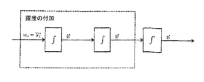
安全性を考慮すると、能動的上下揺れ補償機能が上手く働かなかった場合に備えて、ハンドレバー信号を介して巻上用ウインチを動作できるようにしておく必要がある。軌道設定に用いられる基本概念を用いると、補償動作のための参照軌道の設定と、ハンドレバー信号より生じる軌道の設定との間で、図1に示すような拘束量の配分が行われる。 In consideration of safety, it is necessary to be able to operate the hoisting winch via the hand lever signal in case the active up / down compensation function does not work well. If the basic concept used for the trajectory setting is used, the constraint amount is distributed as shown in FIG. 1 between the setting of the reference trajectory for the compensation operation and the trajectory setting generated from the hand lever signal.
図1において、
![]()
![]()
![]()
![]()
![]()
![]()
軌道設定が独立しているため、上下揺れ補償機能を停止させたときや、あるいは上下揺れ補償機能が完全に故障してしまったとき(例:慣性計測装置IMUの不具合)であっても、ハンドレバーの手動操作によって同一の軌道設定やシーケンス制御を利用することが可能であるため、上下揺れ補償機能を用いた場合と全く同じように運転することが可能となる。 Since the trajectory setting is independent, even if the up / down compensation function is stopped or the up / down compensation function is completely broken (eg, failure of the inertial measurement device IMU) Since it is possible to use the same trajectory setting and sequence control by manual operation of the lever, it becomes possible to operate in exactly the same manner as when using the vertical compensation function.
軌道設定が完全に独立している場合であっても、それぞれで設定された速度と加速度の和が所定の拘束量vmaxとamaxを超えてはならない。そのため、vmaxとamaxは、重み係数0≦kl≦1を用いて分割され、各々の軌道設定機能に割り当てられる(図1参照)。同じように、クレーンオペレータの入力にしたがって動力も分割され、補償機能及び/あるいは荷物の移動を行うために利用される。こうして、補償動作における最大速度と最大加速度は、(1−kl)vmax と (1−kl)amaxになって、繰り出し及び巻き取り動作が重畳されたワイヤロープの軌道の最大速度と最大加速度はklvmaxとklamaxになる。
Even when the trajectory settings are completely independent, the sum of the speed and acceleration set for each must not exceed the predetermined restraining amounts v max and a max . Therefore, v max and a max are divided using
klの値を作業中に変更することもできる。最大許容速度と、最大許容加速度はワイヤロープと荷物を合わせた全体の質量に依存するから、vmaxとamaxは作業中にも変化し得る。したがって、状況に応じて適切な値が軌道設定に引き渡される。 the value of k l can also be changed during the work. Since the maximum allowable speed and the maximum allowable acceleration depend on the total mass of the wire rope and the load, v max and a max can change during work. Therefore, an appropriate value is delivered to the trajectory setting according to the situation.
動力の分割では、制御変数の拘束量を完全に活用できない可能性があるが、クレーンオペレータは能動的上下揺れ補償機能の影響を容易に且つ直感的に調節できる。 In the power split, the constraint amount of the control variable may not be fully utilized, but the crane operator can easily and intuitively adjust the influence of the active up / down compensation function.
重み係数をkl=1に設定した状態は、動的上下揺れ補償機能を停止させた状態に相当し、klの値を操作することによって、補償機能を作動させた状態と停止させた状態との間で滑らかに移行させることが可能となる。 The state in which the weight coefficient is set to k l = 1 corresponds to the state in which the dynamic up / down compensation function is stopped, and the state in which the compensation function is activated and stopped by operating the value of k l It is possible to make a smooth transition between the two.
本章の第1節では、ワイヤロープ吊下箇所の鉛直方向の動作を補償するための参照軌道、すなわち
![]()
![]()
そこで、全時間区間に渡って予測されるワイヤロープ吊下箇所の座標と速度を、それぞれ
![]()
![]()
![]()
![]()
第2節では、荷物を移動させるための軌道、すなわち
![]()
![]()
〈1.1 補償のための参照軌道〉
巻上用ウインチによる補償動作に利用する軌道を設定する際には、ワイヤロープ吊下箇所の鉛直方向の予測された座標と速度を用いて、駆動動作において有効な拘束量を考慮しつつ十分に滑らかな軌道が生成されなければならない。この問題は拘束条件付き最適化問題とみなされ、オンラインでそれぞれの時間ステップ毎に解くことができる。したがって、モデル予測による軌道の生成という意味では、この手法はモデル予測制御の設計に類似している。
<1.1 Reference trajectory for compensation>
When setting the trajectory to be used for the compensation operation by the hoist for winch, use the predicted coordinates and speed in the vertical direction of the wire rope suspension location, and consider the amount of restraint effective in the drive operation. A smooth trajectory must be generated. This problem is considered a constrained optimization problem and can be solved online at each time step. Therefore, in the sense of generating trajectories by model prediction, this method is similar to the design of model predictive control.
最適化のための参照値又は設定値として、ワイヤロープ吊下箇所の鉛直方向の座標
![]()
![]()
![]()
![]()
kl,vmax,amaxによって与えられる拘束量を考慮することによって、補償動作のために最適な時間シーケンスが定められる。 By considering the constraint given by k l , v max , and a max , an optimal time sequence is determined for the compensation operation.
しかしながら、モデル予測制御と同じように、計算された軌道の値のうち最初の値のみがシーケンス制御に使われる。次の時間ステップでは、更新されてより正確となったワイヤロープ吊下箇所の鉛直座標と鉛直速度の予測値を用いて、最適化が循環的に行われる。 However, like the model predictive control, only the first value of the calculated trajectory values is used for the sequence control. In the next time step, optimization is performed cyclically using the updated vertical coordinates of the wire rope suspension and the predicted value of the vertical velocity.
伝統的なモデル予測制御と比較した際の、逐次制御により生成される軌道を用いたモデル予測制御を使う利点とは、軌道生成に比べて長いスキャンタイムで制御と安定化処理が実行されることにある。それゆえ、計算集約的な最適化機能は、より遅いタスク(slower task)へと移行される。 Compared with traditional model predictive control, the advantage of using model predictive control using trajectories generated by sequential control is that control and stabilization processing are executed with a longer scan time than trajectory generation. It is in. Therefore, the computationally intensive optimization function is shifted to a slower task.
他方、この概念に基づき、最適化機能によって有効な解が発見できなかった場合に備え、制御機能とは独立した緊急機能が実装されている。そのような緊急事態において制御機能が頼りにする機能は、ウインチを作動させる簡易化された軌道設定からなる。 On the other hand, based on this concept, an emergency function independent of the control function is implemented in case an effective solution cannot be found by the optimization function. The function that the control function relies on in such an emergency situation consists of a simplified trajectory setting that activates the winch.
〈1.1.1 補償動作を設定するための系のモデル〉
補償動作のための参照軌道が連続関数となるためには、第3次導関数
![]()
![]()
For the reference trajectory for compensation operation to be a continuous function, the third derivative
![]()
![]()
したがって、躍度
![]()

![]()
![]()
![]()
![]()
![]()
図3に示すように本実施形態に係るグリッドを不等間隔とすることによって、区間上で必要とされるグリッドの数を削減している。そうすることによって、解くべき最適制御問題の次元の大きさを小さく保つことができる。区間の終端に向かうに連れて徐々に荒く離散化されていくことによって、軌道の設定に不都合が生じてしまうことはない。なぜならば、鉛直座標と鉛直速度の予測それ自体が、予測区間の終端に向かうに連れて不正確なものとなっていくからである。 As shown in FIG. 3, the number of grids required on the section is reduced by making the grids according to the present embodiment unequal intervals. By doing so, the dimension of the optimal control problem to be solved can be kept small. There is no inconvenience in the setting of the trajectory by being gradually and roughly discretized toward the end of the section. This is because the prediction of the vertical coordinate and the vertical velocity itself becomes inaccurate toward the end of the prediction interval.
離散時間を用いた系の表現であって、特に本実施例に係るグリッドに対して有効な表現は厳密に計算可能であり、その解析解は
〈1.1.2 最適制御問題の定式化と解〉
最適制御問題を解くことによって軌道が設定される。設定された軌道は、ワイヤロープ吊下箇所の鉛直方向の予測動作に可能な限り追従し、それと共に所定の拘束条件を満足しなければならない。
<1.1.2 Formulation and Solution of Optimal Control Problem>
The trajectory is set by solving the optimal control problem. The set trajectory must follow as much as possible the predicted motion in the vertical direction of the wire rope suspension point and, at the same time, satisfy a predetermined constraint condition.
上記の条件を満足するために、次式に与える評価関数
![]()
![]()
![]()
![]()
![]()
![]()
![]()
![]()
![]()
![]()
![]()
![]()
最適制御問題に関連する拘束条件は、駆動のために利用できる動力と、目下選択されている重み係数kl(図1参照)から得られる。したがって、式(1.4)より、系のモデルの状態に対しては
速度と加速度に対する拘束量が、作業中に変化し得るのに対して、躍度jmaxと、躍度の微分
![]()
![]()
作業中の動力の重み係数klはもちろんのこと、最大速度vmaxや最大加速度amaxについても外部から指定されるため、最適制御問題のために用いられる速度と加速度についての拘束量は、必然的に変化させられる。本発明に係る着想は、以下の様に時間の経過に応じて変更を受ける拘束条件を考慮に入れる。拘束条件の変更、すなわち拘束量の値の変更がひとたび行われると、更新された拘束量は予測区間の終端である時間ステップτKpにおいてのみ、当初は考慮に入れられる。そして時間の経過に伴って、更新された拘束量は予測区間の始端側へと押し出されていく。 The maximum weight v max and the maximum acceleration a max as well as the power weighting factor k l during work are specified from the outside, so the constraints on the speed and acceleration used for the optimal control problem inevitably Can be changed. The idea according to the invention takes into account the constraints that are subject to change over time as follows. Once the constraint conditions are changed, i.e., the value of the constraint is changed, the updated constraint is initially taken into account only at the time step τ Kp which is the end of the prediction interval. Then, with the passage of time, the updated constraint amount is pushed out to the start end side of the prediction section.
図4に、速度の拘束量に対するこの手続きが示されている。時刻t0に至る前の拘束量は、予測区間全域に亘って一定となっているとする。そして、図に示すように、時刻t0において拘束量の値がやや減少した値に更新されたとすると、このとき、予測区間の終端、すなわち時間ステップτKpでのみ更新された拘束量が取り入れられる。時間Δτ経過後の時刻t0+Δτでは、予測区間の始端側、すなわち時間ステップτ0に向かう方向へと波及するように、更新された拘束量が押し出されている。しかし、この時点では時刻t0で更新された拘束量が、時間ステップτKp−1に取り入れられるには至っていない。さらに時間Δτ経過後の時刻t0+2Δτにおいて、拘束量がさらに減少した値に更新されたとする。このときも、まずは時間ステップτKpでのみ、更新された拘束量が取り入れられる。時刻t0で更新された拘束量は、予測区間の始端側へとさらに押しだされているが、やはり時間ステップτKp−1の拘束量に影響を及ぼすには至っていない。さらに時間が経過した時刻t0+6Δτでは、時刻t0+Δτにおいて更新された拘束量に留まらず、時刻t0+2Δτにおいて更新された拘束量の影響までもが時間ステップτKp−2に波及している。このように、更新された拘束量が、時間の経過に伴って予測区間の始端側へと徐々に押し出されていく。拘束量を減少させる際には、その微分係数の最大許容値と整合性が取れているかについても注意を払わなければならない。例えば速度の拘束量(1−kl)vmaxについて言えば、目下の加速度の拘束量 (1−kl)amaxをその減衰速度の上限とすることを意味する。更新された拘束量が予測区間に沿って終端側から始端側へと押し出されていくため、拘束条件を満たす初期条件
![]()
![]()
したがって、2次多項式最適化問題(QP問題:Quadratic Programming問題)の形式を取る最適制御問題は、最小化される2次の評価関数(1.5)と、系のモデル(1.4)と、式(1.8),(1.9)で表される不等式によって表される拘束条件によって、完全に与えられる。最初に最適化を実行する際の初期条件は、
![]()
![]()
![]()
![]()
QP問題を実際に解くための計算は、QPソルバー(QP solver)と呼ばれる数値計算方法によって、それぞれの時間ステップ毎に実行される。 The calculation for actually solving the QP problem is executed at each time step by a numerical calculation method called a QP solver.
最適化のための計算工数によると、補償動作のための軌道設定に要するスキャンタイムは、能動的上下揺れ補償機能の他の要件全ての離散時間よりも長い。したがってΔτ>Δtである。 According to the calculation man-hours for optimization, the scan time required to set the trajectory for the compensation operation is longer than the discrete time of all other requirements of the active up / down compensation function. Therefore, Δτ> Δt.
制御のためにより早く参照軌道を利用できることを保証すべく、図2に示す多重積分のシミュレーションが、より短いスキャンタイムΔtで最適化作業とは独立して実行される。最適化によって新しい値が得られるやいなや、シミュレーションのための初期条件として状態ベクトル
![]()
![]()
〈1.2 荷物を移動させるための参照軌道〉
補償動作に類似して、重畳されたハンドレバー操作(図1参照)を制御するためには2階連続的微分可能な参照軌道が必要となる。クレーンオペレータの入力により指定される動作によって、巻上ウインチが急速に向きを変えるような事態は、通常は考えられない。そのため、巻上ウインチの耐久年数を考えても、最低限、設定加速度
![]()
![]()
Similar to the compensation operation, a second-order continuously differentiable reference trajectory is required to control the superimposed hand lever operation (see FIG. 1). A situation in which the hoisting winch changes its direction rapidly due to the operation specified by the crane operator's input is usually unthinkable. Therefore, even if considering the durability of the hoisting winch, at a minimum, the set acceleration
![]()
![]()
図5に示すように躍度は3重積分の入力値としての役割を果たす。連続性についての要請に加えて、設定軌道は目下有効な速度と加速度についての拘束条件も満たさなければならない。拘束条件から定まる速度と加速度についての拘束量、すなわち最大許容速度と最大許容加速度は、ハンドレバー制御に対してはklvmaxとklamaxであることがわかる。 As shown in FIG. 5, the jerk serves as an input value for triple integration. In addition to the requirement for continuity, the set-up trajectory must also satisfy the current effective speed and acceleration constraints. It can be seen that the restraint amounts for speed and acceleration determined from the restraint conditions, that is, the maximum permissible speed and the maximum permissible acceleration are k l v max and k l a max for hand lever control.
クレーンオペレータによって入力されるハンドレバー信号−100≦whh≦100は、目下の最大許容速度klvmaxに対する相対速度の入力値と解釈される。したがって、ハンドレバーによって入力される目標速度を
![]()
![]()
ハンドレバー制御によって軌道を設定する作業について以下に説明する。ハンドレバーの操作によって入力された目標速度を参照して、連続的に微分可能な速度のグラフが生成され、それと共に加速度は連続関数となる。この作業のための手続きとして、所謂、躍度の付加が推奨される。 The operation for setting the trajectory by hand lever control will be described below. With reference to the target speed input by operating the hand lever, a continuously differentiable speed graph is generated, and the acceleration is a continuous function. As a procedure for this work, addition of so-called jerk is recommended.
基本的な考え方は、まずは第1段階として、最大許容加速度に達するまで、最大許容躍度jmaxが多重積分の入力値として作用する。第2段階では、一定の加速度によって速度が増加し、第3段階では最終的に目標速度に達するように最大許容躍度の負値が付加される。 The basic idea is that, as a first stage, the maximum allowable jerk j max acts as an input value for multiple integration until the maximum allowable acceleration is reached. In the second stage, the speed is increased by a constant acceleration, and in the third stage, a negative value of the maximum allowable jerk is added so that the target speed is finally reached.
したがって、躍度の付加を利用した場合は、個々の段階に切り替わるタイミングを表す切り替え時間のみを定めれば良い。図7に、加速度と躍度の振る舞いが、切り替え時間を経てどのように変化するかを例示する。Tl,0は再設定が生じる時間を意味する。時間Tl,1,Tl,2,Tl,3は、各段階に切り替わる切り替え時間にそれぞれが対応し、これらの時間は計算によって定められる。計算の概要については次の段落に示す。
Therefore, when the addition of jerk is used, only the switching time indicating the timing of switching to each stage may be determined. FIG. 7 illustrates how the behavior of acceleration and jerk changes over time. T l, 0 means the time when resetting occurs.
ハンドレバーの操作を通じて新しい状況が発生するやいなや、生成された軌道の再設定が行われる。新しい状況は、目標速度
![]()
![]()
![]()
![]()
![]()
![]()
![]()
![]()
![]()
他方で、
![]()
![]()
![]()
![]()
![]()
![]()
![]()
![]()
![]()
![]()
On the other hand,
![]()
こうした考察から、3つの段階の躍度を切り替える切り替え時間を、以下に説明するように導出することができる。 From these considerations, the switching time for switching the three levels of jerk can be derived as described below.
![]()
![]()
![]()
![]()
![]()
![]()
第2段階で、最大到達加速度の上限値として最大許容加速度klamaxを考慮することによって、単純化を施さない場合における実際の最大到達加速度を、次式のように表すことができる。 In the second stage, by considering the maximum allowable acceleration k l a max as the upper limit value of the maximum reached acceleration, the actual maximum reached acceleration without simplification can be expressed as the following equation.
![]()
![]()
![]()
![]()
![]()
![]()
![]()
![]()
![]()
![]()
図8に、ここまでに提示された方法を用いて生成された軌道の振る舞いを例示する。図中のグラフは、式 (1.24)によって起こり得る2通りのケースの両方を表している。第1のケースの場合、時間t=1sで最大許容加速度に達し、一定の加速度によって加速する段階へと続く。第2のケースは時間t=3.5sで発生する。第2のケースでは、ハンドレバーの位置が原因で、最大許容加速度には達しない。その結果、第1の切り替え時間と第2の切り替え時間が一致し、ΔT2=0が採用される。図5によると、対応する座標の軌道は速度曲線を積分することによって計算され、起動時には、巻上ウインチから繰り出されたワイヤロープの目下の長さを用いて座標の値が初期化される。 FIG. 8 illustrates the behavior of the trajectory generated using the methods presented so far. The graph in the figure represents both of the two cases that can occur according to equation (1.24). In the case of the first case, the maximum allowable acceleration is reached at time t = 1 s, and the process continues to accelerate with a constant acceleration. The second case occurs at time t = 3.5 s. In the second case, the maximum allowable acceleration is not reached due to the position of the hand lever. As a result, the first switching time and the second switching time coincide with each other, and ΔT 2 = 0 is adopted. According to FIG. 5, the trajectory of the corresponding coordinate is calculated by integrating the velocity curve, and at the time of activation, the coordinate value is initialized using the current length of the wire rope drawn out from the winding winch.
〈2 巻上ウインチの動作概念〉
原則として、巻上ウインチの動作は2種の異なる運用モードからなる。第1の運用モードは、ワイヤロープに吊された荷物の鉛直方向の動作から船の揺れの影響を取り除くために能動的上下揺れ補償機能が機能するモードであって、第2の運用モードは、荷物を海底に置いた際に生じ得るワイヤロープの弛緩を阻止するための張力保持モードである。吊荷を海底に置く際には、最初に上下揺れ補償機能が動作し、荷置作業の遂行を検知すると自動的に張力保持機能へと切り替わる。図9に関連する参照変数と制御変数を用いた包括的な概念図を示す。
<2 Winding winch operation concept>
In principle, the operation of the hoisting winch consists of two different operating modes. The first operation mode is a mode in which the active up / down compensation function functions in order to remove the influence of ship sway from the vertical movement of the load suspended on the wire rope, and the second operation mode is: This is a tension holding mode for preventing the relaxation of the wire rope that may occur when the load is placed on the seabed. When placing a suspended load on the seabed, the up / down compensation function operates first, and when the execution of the loading operation is detected, the function automatically switches to the tension holding function. FIG. 10 shows a comprehensive conceptual diagram using reference variables and control variables related to FIG. 9.
2種の異なる運用モードは、それぞれが単独で備えられても良い。加えて以下に記載されるように、船上でのクレーンの利用や能動的上下揺れ補償機能とは関係のない用途にも張力保持モードを利用することも可能である。 Two different operation modes may be provided independently. In addition, as described below, the tension holding mode can also be used for applications unrelated to the use of cranes on board and the active up / down compensation function.
能動的上下揺れ補償機能を用いた結果、巻上ウインチの動作によってワイヤロープ吊下箇所
![]()
![]()
![]()
![]()
![]()
![]()
![]()
![]()
張力保持モードが機能している間、荷物へ課せられるワイヤロープの張力Fslは、ワイヤロープの弛緩を避けるべく一定に保つように制御される。したがって、張力保持モードが機能している間、ハンドレバー機能は一時的に使用不能となって、ハンドレバーを用いて出力された信号に基づいて設定された軌道は最早参照されないことになる。それに続いて、フィードフォワード制御と安定化機能を備えた2自由度構造によってウインチの動作制御がもたらされる。 While the tension holding mode is functioning, the wire rope tension F sl applied to the load is controlled to remain constant to avoid the wire rope relaxation. Therefore, while the tension holding mode is functioning, the hand lever function is temporarily disabled, and the trajectory set based on the signal output using the hand lever is no longer referred to. Subsequently, winch motion control is provided by a two-degree-of-freedom structure with feedforward control and stabilization functions.
荷物の厳密な位置座標zlと、荷物へ課せられるワイヤロープの張力Fslを制御のための測定量として利用することはできない。なぜならば、長いワイヤロープを用いて海底深くで作業を行うため、クレーンのフック部にセンサー装置を取り付けられないためである。その上、吊り下げられた荷物の種類や形状についての情報は存在しない。したがって、荷物の質量mlや、流体力学的質量増加係数(coefficient of the hydrodynamic increase in mass)Ca、抵抗係数Cd及び湿潤体積∇lといった、個々の荷物を特徴付けるパラメータは通常わからないため、荷物の位置を信頼できる精度で推定することは、現実的にはほぼ不可能である。 The exact position coordinates zl of the load and the wire rope tension Fsl imposed on the load cannot be used as measurement quantities for control. This is because the sensor device cannot be attached to the hook portion of the crane because the work is performed deep in the sea floor using a long wire rope. In addition, there is no information about the type and shape of the suspended luggage. Therefore, luggage and the mass m l of for hydrodynamic mass gain coefficient (coefficient of the hydrodynamic increase in mass ) C a, such resistance coefficient C d and wet volume ∇ l, parameters characterizing the individual luggage not know usually luggage In reality, it is almost impossible to estimate the position of the position with a reliable accuracy.
結局のところ、繰り出されたワイヤロープの長さlsと、それに対応する速度
![]()
![]()
![]()
![]()
〈2.1 能動的上下揺れ補償機能のための動作〉
図10は能動的上下揺れ補償機能のための巻上ウインチの制御動作を周波数領域で示したブロック回路図である。図からわかるように、ワイヤロープ長 yh=lsとワイヤロープの速度
![]()
![]()
FIG. 10 is a block circuit diagram showing, in the frequency domain, the control operation of the hoist winch for the active vertical compensation function. As can be seen, wire rope length y h = l s and wire rope speed
![]()
![]()
補償変数Uh(s)から、繰り出されたワイヤロープ長Yh(s)への駆動系の伝達関数は、IT1系(IT1 system)として近似され、
安定化機能系とKa(s)と駆動系Gh(s)からなる閉回路の伝達関数は、図10から
![]()
![]()
![]()
![]()
![]()
![]()
![]()
![]()
![]()
![]()
〈2.2 荷置作業の検知〉
荷物が海底に当たるやいなや、能動的上下揺れ補償機能から張力保持機能へと直ちに切り替えられるべきである。機能の切り替えを実現するためには、荷置作業の検知が必要となる(図9参照)。荷置作業を検知し、その後、速やかに張力保持機能へと切り替えるために、ワイヤロープを単純なバネ質点系として近似して考察する。この近似の下ではワイヤロープ吊下箇所に作用する力は、次式のように表すことができる。
![]()
As soon as the load hits the seabed, it should immediately switch from the active up / down compensation function to the tension holding function. In order to realize switching of functions, it is necessary to detect loading work (see FIG. 9). In order to detect the loading operation and then quickly switch to the tension holding function, the wire rope is approximated and considered as a simple spring mass system. Under this approximation, the force acting on the wire rope suspension location can be expressed as:
![]()
式(2.7)において、kcとΔlcは各々ワイヤロープの弾性に対応するバネ定数と、ワイヤロープの変位に対応するバネの変位を意味する。他方、特許文献1に示すように、ワイヤロープ及び荷物によってもたらされる重量全てが、ワイヤロープの変位Δlcに対応するひずみの発生に寄与すると仮定すると、ワイヤロープに加わる重力と弾性力の釣り合いから、次の関係が成立する。
In equation (2.7), k c and Δl c mean the spring constant corresponding to the elasticity of the wire rope and the displacement of the spring corresponding to the displacement of the wire rope, respectively. On the other hand, as shown in
![]()
![]()
![]()
![]()
![]()
![]()
![]()
![]()
ワイヤロープ系を近似することによって、海底への荷置作業を検知するための条件式を導出することが可能となる。静止状態でワイヤロープ吊下箇所に作用する力は、繰り出されたワイヤロープに働く重力μslsgと、荷物に働く有効的な重力megからなる。ゆえに、海底上に荷物が置かれた際にワイヤロープ吊下箇所に作用する力Fcを、次式に示すように近似することができる。 By approximating the wire rope system, it is possible to derive a conditional expression for detecting loading work on the seabed. Force acting on the cable suspension point in a static state, the gravitational mu s l s g acting on fed-out wire rope, comprising an effective gravitational m e g acting on luggage. Thus, the force F c acting on the wire rope suspension point when the baggage is placed on the seabed can be approximated as shown in the following equation.
![]()
![]()
![]()
![]()
・ワイヤロープ吊下箇所に作用する力の減少量は、ある閾値よりも小さくなければならない。
![]()
![]()
・ワイヤロープ吊下箇所に作用する力の時間微分は、ある閾値よりも小さくなければならない。
![]()
![]()
・クレーンオペレータは鉛直下向きへと荷物を移動させなければならない。この条件は、ハンドレバー信号によって設定された軌道が次式を満たすことで満足される。
![]()
![]()
・水中に没入する際に起こり得る誤検知を防止するために、ワイヤロープをある長さ以上、繰り出さなければならない。
![]()
![]()
ワイヤロープ吊下箇所に作用する力の減少量ΔFcは、測定された力の信号Fcと、Fcの直近のピーク値
![]()
![]()
ワイヤロープの動的な固有振動によって生じる誤検知は、条件(2.14)と条件(2.15)を同時に満たすように要請することによって排除される。すなわち、動的な固有振動を受けて力の信号Fcも振動するため、直近のピーク値
![]()
![]()
![]()
![]()
![]()
![]()
力の信号の直近のピーク値を用いて、ワイヤロープ吊下箇所に作用する力の減少量の閾値を以下の様に表すことができる。
![]()
![]()
![]()
![]()
![]()
![]()
![]()
![]()
![]()
![]()
![]()
![]()
張力保持機能においては、位置の制御ではなく力の制御が行われるため、目標の力
![]()
![]()
![]()
![]()
Fc,statはワイヤロープ吊下箇所で測定される力Fcの静的な要素を意味し、測定された力の信号を、対応するローパスフィルタに通すことによって得られる。フィルタを通すことによって生じる群遅延は問題とはならない。なぜならば、興味の対象は静的な力の要素に過ぎず、これに対して遅延が重大な影響を及ぼす訳ではないからである。荷物に作用する全ての静的な力の和に、ワイヤロープ吊下箇所に作用するワイヤロープの重量をさらに考慮することによって、力の目標値を得る。 F c, stat means a static element of the force F c measured at the wire rope suspension point, and is obtained by passing the measured force signal through a corresponding low-pass filter. Group delay caused by filtering is not a problem. This is because the object of interest is only a static force element, and delay does not have a significant effect on it. The target value of the force is obtained by further taking into account the weight of the wire rope acting on the suspended portion of the wire rope in the sum of all static forces acting on the load.
![]()
![]()
![]()
![]()
海底から荷物を吊り上げる際には、張力保持モードから、自由に荷物を吊り下げられる能動的上下揺れ補償モードへと、クレーンオペレータによって手動で切り替えられる。 When lifting a load from the seabed, the crane operator manually switches from the tension holding mode to the active up / down compensation mode in which the load can be freely suspended.
〈2.3 張力保持モードの動作〉
図11は張力保持モードにおける巻上ウインチの実行動作を示す、周波数領域におけるブロック回路図である。図10で示された制御構造とは対照的に、ウインチ系の出力Yh(s)ではなく、ワイヤロープ系の出力Fc(s)、すなわちワイヤロープ吊下箇所で測定された力がフィードバックされる。式(2.12)によると、測定された力Fc(s)は力の変化量ΔFc(s)と、図10中ではM(s)と記されている静的な重力meg+μslsgを用いて表される。実際の制御において、ワイヤロープ系は再びバネ質点系と近似される。
<2.3 Operation in tension holding mode>
FIG. 11 is a block circuit diagram in the frequency domain showing the execution operation of the winding winch in the tension holding mode. In contrast to the control structure shown in FIG. 10, not the winch output Y h (s) but the wire rope output F c (s), ie, the force measured at the wire rope suspension point is fed back. Is done. According to equation (2.12), the measured force F c (s) is the force of the change amount [Delta] F c (s), static gravity are marked as M (s) is in FIG. 10 m e g + μ It is expressed using s l s g. In actual control, the wire rope system is again approximated to the spring mass point system.
2自由度構造を有するフィードフォワード制御F(s)は、能動的上下揺れ補償機能のためのフィードフォワード制御と同一であり、それぞれが式(2.2)と式(2.3)で与えられる。しかしながら、張力保持モードにおいてハンドレバー信号は使用されないため、参照軌道は補償動作のための負の速度
![]()
![]()
![]()
![]()
![]()
![]()
測定される出力Fc(s)は図11から得られ、次式のように表される。
![]()
![]()
式(2.22)から明らかな様に、補償誤差Ea(s)は安定な伝達関数GCT,1(s)による補償を受けるため、ウインチの位置は間接的に安定化される。この場合も制御装置Ks(s)が満たすべき条件は、期待される力の参照値に対応する信号
![]()
![]()
![]()
![]()
1 クレーン
2 ワイヤローププーリ(ワイヤロープ吊下箇所)
3 荷物
4 ワイヤロープ
5 巻上装置
6 フロート
1 crane
2 Wire rope pulley (wire rope suspended part)
3 Luggage
4 Wire rope
5 Hoisting device
6 Float
Claims (15)
上記上下揺れ補償機能は、巻上装置の動作を計算する際に該巻上装置における1つ以上の拘束量を考慮に入れるように構成されており、
上記上下揺れ補償機能は、上記巻上装置の最大許容速度を考慮する
ことを特徴とするクレーン制御装置。 A crane control device for a crane having a hoisting device for hanging a load on a wire rope and lifting the wire rope, and causing at least a swing generated at a wire rope suspension location and / or a loading location due to vertical swinging In a crane control device having an active up / down compensation function for operating the hoisting device to partially compensate,
The up and down compensation function is configured to take into account one or more restraints in the hoisting device when calculating the operation of the hoisting device ;
The crane control device , wherein the up and down compensation function considers a maximum allowable speed of the hoisting device.
上記上下揺れ補償機能は、さらに最大許容躍度及び/又は最大許容加速度及び/又は最大許容動力を考慮し、
上記巻上装置における1つ以上の拘束量、該巻上装置における上記最大許容速度及び/又は上記巻上装置における上記最大許容加速度及び/又は動力を計算する計算機能を備え、
上記計算機能は繰り出された上記ワイヤロープの長さ及び/又は上記ワイヤロープの張力及び/又は上記巻上装置の駆動のために利用できる上記動力を考慮する
ことを特徴とするクレーン制御装置。 In the crane control device according to claim 1,
The heave compensation further consideration of the maximum permissible jerk and / or the maximum permissible acceleration Do及 beauty / or maximum allowable power,
A calculation function for calculating one or more restraints in the hoisting device, the maximum allowable speed in the hoisting device and / or the maximum allowable acceleration and / or power in the hoisting device;
The crane control device according to claim 1, wherein the calculation function takes into account the length of the wire rope fed out and / or the tension of the wire rope and / or the power available for driving the hoisting device.
上記巻上装置の駆動部が、アキュムレータに接続されている
ことを特徴とするクレーン制御装置。 In the crane control device according to claim 1 or 2,
A crane control device, wherein the drive unit of the hoisting device is connected to an accumulator.
上記ワイヤロープ吊下箇所及び/又は荷置箇所の動作予測を参照した上で、上記巻上装置における上記拘束量を考慮することによって軌道を決定する経路設定モジュールを備え、
上記経路設定モジュールは、ワイヤロープ吊下箇所及び/又は荷置箇所の上記動作予測を参照した上で、上記巻上装置における上記拘束量を考慮することによって軌道を決定する最適化機能を有し、
上記最適化機能は、ワイヤロープ吊下箇所及び/又は荷置箇所の動作に起因する残余動作を最小化する
ことを特徴とするクレーン制御装置。 In the crane control device according to any one of claims 1 to 3,
A path setting module that determines the trajectory by considering the amount of restraint in the hoisting device after referring to the operation prediction of the wire rope hanging part and / or the loading place,
The path setting module has an optimization function for determining the trajectory by referring to the motion prediction of the wire rope hanging part and / or the loading part and taking the constraint amount in the hoisting device into consideration. ,
The crane control device characterized in that the optimization function minimizes a residual operation caused by the operation of the wire rope hanging part and / or the loading part.
上記上下揺れ補償機能は、ワイヤロープ吊下箇所及び/又は荷置箇所の動作予測を参照し、上記巻上装置における位置及び/又は速度及び/又は加速度の軌道を計算する経路設定モジュールを備え、
上記軌道が、上記巻上装置のサブシーケンス制御のための設定値に取り入れられる
ことを特徴とするクレーン制御装置。 A crane control device for a crane having a hoisting device for hanging a load on a wire rope and lifting the wire rope, and causing at least a swing generated at a wire rope suspension location and / or a loading location due to vertical swinging The crane control device according to any one of claims 1 to 4, further comprising a vertical swing compensation function for operating the hoisting device so as to partially compensate.
The vertical shake compensation function includes a path setting module that calculates the trajectory of the position and / or speed and / or acceleration in the hoisting device with reference to the motion prediction of the wire rope suspension point and / or the loading point,
The crane control device, wherein the track is incorporated in a set value for sub-sequence control of the hoisting device.
測定値を巻上用ウインチの位置及び/又は速度へとフィードバックし、及び/又はフィードフォワード機能によって上記巻上用ウインチの駆動部の動的挙動を考慮に入れる
ことを特徴とするクレーン制御装置。 The crane control device according to claim 5,
A crane control device characterized in that the measured value is fed back to the position and / or speed of the hoisting winch and / or the dynamic behavior of the hoisting winch drive is taken into account by a feedforward function.
オペレータによる入力を参照して上記巻上装置を作動させるオペレータ制御機能を有し、
上記上下揺れ補償機能のための軌道と上記オペレータ制御機能のための軌道とを、それぞれ単独で計算する2つの独立した経路設定モジュールを備え、
さらに2つの独立した経路設定モジュールによって指定される軌道は加算され、上記巻上装置の制御及び/又は調整のための設定値として供給される
ことを特徴とするクレーン制御装置。 In the crane control device according to any one of claims 1 to 6,
Referring to operator input has operating data control function for operating the hoisting device,
Comprising two independent path setting modules that independently calculate the trajectory for the up / down compensation function and the trajectory for the operator control function,
Further, the trajectory specified by two independent path setting modules is added and supplied as a set value for controlling and / or adjusting the hoisting device.
上記上下揺れ補償機能は、巻上装置の動作を計算する際に該巻上装置における1つ以上の拘束量を考慮に入れるように構成されており、
オペレータによる入力を参照して上記巻上装置を作動させるオペレータ制御機能を有し、
上記上下揺れ補償機能のための軌道と上記オペレータ制御機能のための軌道とを、それぞれ単独で計算する2つの独立した経路設定モジュールを備え、
さらに2つの独立した経路設定モジュールによって指定される軌道は加算され、上記巻上装置の制御及び/又は調整のための設定値として供給され、
1つ以上の運動学的拘束量が、上下揺れ調整機能とオペレータ制御機能との間で調整自在に配分され、
上記配分の調整は、1つ以上の重み係数によってもたらされ、該重み係数を介して該巻上装置の最大許容動力及び/又は最大許容速度及び/又は最大許容加速度が、上記上下揺れ補償機能と上記オペレータ制御機能との間で分割される
ことを特徴とするクレーン制御装置。 A crane control device for a crane having a hoisting device for hanging a load on a wire rope and lifting the wire rope, and causing at least a swing generated at a wire rope suspension location and / or a loading location due to vertical swinging In a crane control device having an active up / down compensation function for operating the hoisting device to partially compensate,
The up and down compensation function is configured to take into account one or more restraints in the hoisting device when calculating the operation of the hoisting device;
An operator control function for operating the hoisting device with reference to an input by an operator;
Comprising two independent path setting modules that independently calculate the trajectory for the up / down compensation function and the trajectory for the operator control function,
Furthermore, the trajectories specified by the two independent path setting modules are added and supplied as set values for the control and / or adjustment of the hoisting device,
One or more kinematic restraints are apportionably distributed between the up and down adjustment function and the operator control function;
The adjustment of the distribution is effected by one or more weighting factors, through which the maximum allowable power and / or maximum allowable speed and / or maximum allowable acceleration of the hoisting device can be And a crane control device divided between the operator control function and the operator control function.
上記上下揺れ補償機能は、巻上装置の動作を計算する際に該巻上装置における1つ以上の拘束量を考慮に入れるように構成されており、
上記ワイヤロープ吊下箇所及び/又は荷置箇所の動作予測を参照した上で、上記巻上装置における上記拘束量を考慮することによって軌道を決定する経路設定モジュールを備え、
上記経路設定モジュールは、ワイヤロープ吊下箇所及び/又は荷置箇所の上記動作予測を参照した上で、上記巻上装置における上記拘束量を考慮することによって軌道を決定する最適化機能を有し、
上記最適化機能は、ワイヤロープ吊下箇所及び/又は荷置箇所の動作に起因する残余動作を最小化し、
上記上下揺れ補償機能が有する上記最適化機能は、上記巻上装置の制御及び/又は調整に用いられる目標軌道を決定し、
上記最適化機能は、ワイヤロープ吊下箇所において更新された動作予測に基づいて、各時間ステップ毎に最適化を実行可能であり、
上記目標軌道の各々の最初の値が制御のために用いられ、
上記最適化機能は、制御よりも長いスキャンタイムで動作し、
上記最適化機能は、有効な解を得られない場合には緊急軌道設定を利用する
ことを特徴とするクレーン制御装置。 A crane control device for a crane having a hoisting device for hanging a load on a wire rope and lifting the wire rope, and causing at least a swing generated at a wire rope suspension location and / or a loading location due to vertical swinging In a crane control device having an active up / down compensation function for operating the hoisting device to partially compensate,
The up and down compensation function is configured to take into account one or more restraints in the hoisting device when calculating the operation of the hoisting device;
A path setting module that determines the trajectory by considering the amount of restraint in the hoisting device after referring to the operation prediction of the wire rope hanging part and / or the loading place,
The path setting module has an optimization function for determining the trajectory by referring to the motion prediction of the wire rope hanging part and / or the loading part and taking the constraint amount in the hoisting device into consideration. ,
The above optimization function minimizes the residual movement caused by the movement of the wire rope hanging part and / or the loading part,
The optimization function of the vertical shake compensation function determines a target trajectory used for control and / or adjustment of the hoisting device,
The above optimization function can perform optimization for each time step based on the motion prediction updated at the wire rope hanging location,
The first value of each of the target trajectories is used for control,
The above optimization function operates with a scan time longer than the control,
The crane control device characterized in that the optimization function uses emergency trajectory setting when an effective solution cannot be obtained.
センサーデータから目下の上下揺れ動作を決定する測定装置と、
決定された目下の上下揺れ動作と上下揺れ動作を記述する物理モデルとを参照して、ワイヤロープ吊下箇所及び/又は荷置箇所の以後の動作を予測する予測装置とを備え、
予測装置に用いられる上下揺れ動作を記述する物理モデルは、上記クレーン及び/又は上記荷置箇所が設けられたフロートの動的挙動といった性質には依存しない
ことを特徴とするクレーン制御装置。 In the crane control device according to any one of claims 1 to 9,
A measuring device that determines the current vertical motion from sensor data;
A prediction device for predicting the subsequent movement of the wire rope suspension part and / or the loading part with reference to the determined vertical motion and the physical model describing the vertical movement;
A crane control device characterized in that a physical model describing a vertical swing motion used in a prediction device does not depend on properties such as dynamic behavior of the crane and / or a float provided with the loading place.
上記予測装置は、上記測定装置による上記センサーデータから、周波数解析を用いて上記上下揺れ動作における支配的な振動モードを決定し、上記決定された支配的な振動モードを参照して上記上下揺れ動作を記述する物理モデルを生成し、
上記予測装置は、上記測定装置による上記センサーデータを参照して上記物理モデルを連続的にパラメータ化し、
オブザーバがパラメータ化され、
振動モードの振幅と位相がパラメータ化され、及び/又は上記物理モデルは、上記上下揺れ動作における上記支配的な振動モードが変更を受けた際に更新される
ことを特徴とするクレーン制御装置。 In the crane control device according to claim 10,
The prediction device determines a dominant vibration mode in the up-and-down motion using frequency analysis from the sensor data by the measurement device, and refers to the determined dominant vibration mode and moves the up-and-down motion. Generate a physical model that describes
The prediction device continuously parameterizes the physical model with reference to the sensor data from the measurement device,
The observer is parameterized,
A crane control device characterized in that the amplitude and phase of a vibration mode are parameterized and / or the physical model is updated when the dominant vibration mode in the up and down motion is changed.
上記上下揺れ補償機能は、上記巻上装置の動作を計算する際に該巻上装置における1つ以上の拘束量を考慮に入れ、
上記上下揺れ補償機能は、上記ワイヤロープ吊下箇所及び/又は荷置箇所の予測動作を参照して巻上装置の位置及び/又は速度及び/又は加速度の軌道を計算し、
上記軌道は、上記巻上装置のサブシーケンス制御のための設定値に取り入れられる
ことを特徴とするクレーンの制御方法。 A control method for a crane having a hoisting device for hanging a load on a wire rope and lifting it, and at least partially causing a swing that occurs in a wire rope suspension location and / or loading location due to vertical swinging In a crane control method having a vertical shake compensation function for automatically operating the hoisting device to compensate,
The up and down compensation function takes into account one or more restraints in the hoisting device when calculating the operation of the hoisting device,
The vertical swing compensation function calculates the trajectory of the position and / or speed and / or acceleration of the hoisting device with reference to the predicted operation of the wire rope suspension location and / or loading location,
The crane control method, wherein the track is incorporated in a set value for sub-sequence control of the hoisting device.
ことを特徴とする、請求項13に記載のクレーンの制御方法。 The crane control method according to any one of claims 1 to 11, wherein the crane control device according to any one of claims 1 to 11 is used.
ことを特徴とするソフトウェア。 Software comprising a program code for executing the crane control method according to claim 13 or 14.
Applications Claiming Priority (2)
| Application Number | Priority Date | Filing Date | Title |
|---|---|---|---|
| DE102012004803.3 | 2012-03-09 | ||
| DE102012004803A DE102012004803A1 (en) | 2012-03-09 | 2012-03-09 | Crane control with drive limitation |
Publications (2)
| Publication Number | Publication Date |
|---|---|
| JP2013184826A JP2013184826A (en) | 2013-09-19 |
| JP6243128B2 true JP6243128B2 (en) | 2017-12-06 |
Family
ID=47522219
Family Applications (1)
| Application Number | Title | Priority Date | Filing Date |
|---|---|---|---|
| JP2013046505A Active JP6243128B2 (en) | 2012-03-09 | 2013-03-08 | Crane control device, crane, crane control method, and software for executing the control method |
Country Status (6)
| Country | Link |
|---|---|
| US (1) | US9266700B2 (en) |
| EP (1) | EP2636632B1 (en) |
| JP (1) | JP6243128B2 (en) |
| KR (1) | KR20130103365A (en) |
| CN (1) | CN103303797B (en) |
| DE (1) | DE102012004803A1 (en) |
Families Citing this family (20)
| Publication number | Priority date | Publication date | Assignee | Title |
|---|---|---|---|---|
| DE102012004802A1 (en) * | 2012-03-09 | 2013-09-12 | Liebherr-Werk Nenzing Gmbh | Crane control with distribution of a kinematically limited size of the hoist |
| JP5829968B2 (en) * | 2012-04-06 | 2015-12-09 | トヨタ自動車株式会社 | Articulated robot, joint cooperative control apparatus and method thereof |
| CN105439016A (en) * | 2014-10-11 | 2016-03-30 | 徐州重型机械有限公司 | Working range compensation method and device for crane |
| GB2538986A (en) * | 2015-06-02 | 2016-12-07 | Marine Electrical Consulting Ltd | Method and apparatus for adaptive motion compensation |
| US9849944B2 (en) * | 2015-10-05 | 2017-12-26 | Keppel Offshore & Marine Technology Centre Pte. Ltd. | System and method for guiding cargo transfer between two bodies |
| CN105523476B (en) * | 2015-12-31 | 2017-09-15 | 北京起重运输机械设计研究院 | A kind of bridge crane is anti-to shake control method and system |
| EP3226095A1 (en) | 2016-03-31 | 2017-10-04 | Fraunhofer-Gesellschaft zur Förderung der angewandten Forschung e.V. | System and method of navigation of an autonomously navigated submersible vehicle at entering a catch station |
| DE102017125715A1 (en) * | 2016-11-09 | 2018-05-09 | Liebherr-Werk Biberach Gmbh | Device for compensation of diagonal tension in cranes |
| CN110337416B (en) * | 2017-02-28 | 2022-01-11 | J.雷.麦克德莫特股份有限公司 | Offshore ship-to-ship lifting with target tracking assistance |
| CN114380219A (en) * | 2017-04-24 | 2022-04-22 | 伊特里克公司 | Motion compensated crane for use on a marine vessel |
| WO2018228809A1 (en) * | 2017-06-12 | 2018-12-20 | Siemens Wind Power A/S | Offshore wind turbine installation arrangement |
| EP3461783B1 (en) * | 2017-09-29 | 2019-11-13 | B&R Industrial Automation GmbH | Lifting device and method for controlling a lifting device |
| JP7151223B2 (en) * | 2018-07-09 | 2022-10-12 | 株式会社タダノ | Cranes and crane control methods |
| JP7172243B2 (en) * | 2018-07-25 | 2022-11-16 | 株式会社タダノ | Cranes and crane control systems |
| JP7172256B2 (en) * | 2018-07-31 | 2022-11-16 | 株式会社タダノ | crane |
| EP3653562A1 (en) * | 2018-11-19 | 2020-05-20 | B&R Industrial Automation GmbH | Method and oscillating regulator for regulating oscillations of an oscillatory technical system |
| EP4043967A4 (en) * | 2019-10-11 | 2023-11-01 | Tadano Ltd. | Control system, and crane |
| CN112456361A (en) * | 2020-11-25 | 2021-03-09 | 西北工业大学 | Control method for reducing swing amplitude of underwater extension set of hydraulic winch for hoisting sonar |
| CN113928991B (en) * | 2021-09-09 | 2023-09-01 | 山东建筑大学 | Method and device for monitoring arm end track of crane boom of tower crane |
| CN115924740B (en) * | 2022-12-29 | 2023-11-03 | 中铁建工集团有限公司 | Asynchronous lifting control method for large-span steel structure |
Family Cites Families (17)
| Publication number | Priority date | Publication date | Assignee | Title |
|---|---|---|---|---|
| GB2132972B (en) * | 1983-01-05 | 1986-01-15 | Ruston Bucyrus Ltd | Crane hoist protection system |
| DE3418026A1 (en) * | 1984-05-15 | 1985-11-21 | Mannesmann Rexroth GmbH, 8770 Lohr | Winch for picking up floating loads, especially in a swell |
| US4624450A (en) | 1984-09-20 | 1986-11-25 | Paccar Inc. | Constant tension hoisting system |
| DE3643114C2 (en) | 1986-01-13 | 1995-06-01 | Rexroth Mannesmann Gmbh | Winch control with swell tracking device |
| DE19645812C1 (en) | 1996-11-07 | 1998-02-26 | Stahl R Foerdertech Gmbh | Electric hoist with microprocessor control system |
| US6216789B1 (en) * | 1999-07-19 | 2001-04-17 | Schlumberger Technology Corporation | Heave compensated wireline logging winch system and method of use |
| WO2002027684A1 (en) | 2000-09-27 | 2002-04-04 | Oceaneering International, Inc. | Method and system for high speed deployment monitoring |
| ATE322454T1 (en) * | 2000-10-19 | 2006-04-15 | Liebherr Werk Nenzing | CRANE OR EXCAVATOR FOR HANDLING A LOAD HANGING ON A LOADS WITH LOAD SWING DAMPING |
| US6505574B1 (en) * | 2001-09-05 | 2003-01-14 | The United States Of America As Represented By The Secretary Of The Navy | Vertical motion compensation for a crane's load |
| US7793763B2 (en) * | 2003-11-14 | 2010-09-14 | University Of Maryland, Baltimore County | System and method for damping vibrations in elevator cables |
| GB0406336D0 (en) * | 2004-03-19 | 2004-04-21 | Subsea 7 Uk | Apparatus and method |
| US7599762B2 (en) * | 2005-08-24 | 2009-10-06 | Rockwell Automatino Technologies, Inc. | Model-based control for crane control and underway replenishment |
| NO336258B1 (en) * | 2007-09-19 | 2015-07-06 | Nat Oilwell Varco Norway As | Method and device for lift compensation. |
| DE102008024513B4 (en) * | 2008-05-21 | 2017-08-24 | Liebherr-Werk Nenzing Gmbh | Crane control with active coast sequence |
| DE102009032269A1 (en) | 2009-07-08 | 2011-01-13 | Liebherr-Werk Nenzing Gmbh | Crane control for controlling a hoist of a crane |
| DE102009041662A1 (en) * | 2009-09-16 | 2011-03-24 | Liebherr-Werk Nenzing Gmbh, Nenzing | System for detecting the load mass of a hanging on a hoist rope of a crane load |
| CN202054550U (en) * | 2011-04-28 | 2011-11-30 | 中船华南船舶机械有限公司 | Constant-tension wave compensation device |
-
2012
- 2012-03-09 DE DE102012004803A patent/DE102012004803A1/en not_active Withdrawn
- 2012-12-12 EP EP12008290.4A patent/EP2636632B1/en active Active
-
2013
- 2013-02-27 KR KR1020130021062A patent/KR20130103365A/en not_active Application Discontinuation
- 2013-03-07 US US13/788,856 patent/US9266700B2/en active Active
- 2013-03-08 JP JP2013046505A patent/JP6243128B2/en active Active
- 2013-03-11 CN CN201310076824.2A patent/CN103303797B/en active Active
Also Published As
| Publication number | Publication date |
|---|---|
| US9266700B2 (en) | 2016-02-23 |
| EP2636632A1 (en) | 2013-09-11 |
| CN103303797B (en) | 2016-12-28 |
| US20130245817A1 (en) | 2013-09-19 |
| KR20130103365A (en) | 2013-09-23 |
| EP2636632B1 (en) | 2019-02-13 |
| JP2013184826A (en) | 2013-09-19 |
| CN103303797A (en) | 2013-09-18 |
| DE102012004803A1 (en) | 2013-09-12 |
Similar Documents
| Publication | Publication Date | Title |
|---|---|---|
| JP6243128B2 (en) | Crane control device, crane, crane control method, and software for executing the control method | |
| JP6193590B2 (en) | Crane control device, crane, use of crane control device, crane operating method, and software for executing the operating method | |
| JP6189055B2 (en) | Crane control device, crane, crane control method, method of using crane control device, and software for executing these methods | |
| CN103318776B (en) | Active heave heave compensation control system and control method | |
| CN104276526B (en) | Reduce method and the elevator device that elevator rope waves | |
| US9212031B2 (en) | Crane control apparatus | |
| US9434577B2 (en) | Semi-active feedback control of elevator rope sway | |
| JP4795228B2 (en) | Crane or excavator with optimal movement guidance for handling rope-loaded luggage | |
| US9278829B2 (en) | Method and system for controlling sway of ropes in elevator systems by modulating tension on the ropes | |
| EP3303204B1 (en) | Method and apparatus for adaptive motion compensation | |
| JP5318103B2 (en) | Elevator equipment | |
| Vázquez et al. | Control of a parametrically excited crane: A vector Lyapunov approach | |
| JP6521887B2 (en) | Elevator system, method for controlling operation of elevator system and non-transitory computer readable medium | |
| JP6453075B2 (en) | Method and apparatus for controlling steadying of trolley crane | |
| Küchler et al. | Nonlinear control of an active heave compensation system with time-delay | |
| JP2006225138A (en) | Device and method for calculating swing characteristic of suspended load |
Legal Events
| Date | Code | Title | Description |
|---|---|---|---|
| A621 | Written request for application examination |
Free format text: JAPANESE INTERMEDIATE CODE: A621 Effective date: 20160120 |
|
| A977 | Report on retrieval |
Free format text: JAPANESE INTERMEDIATE CODE: A971007 Effective date: 20161215 |
|
| A131 | Notification of reasons for refusal |
Free format text: JAPANESE INTERMEDIATE CODE: A131 Effective date: 20170131 |
|
| A601 | Written request for extension of time |
Free format text: JAPANESE INTERMEDIATE CODE: A601 Effective date: 20170427 |
|
| A521 | Request for written amendment filed |
Free format text: JAPANESE INTERMEDIATE CODE: A523 Effective date: 20170510 |
|
| TRDD | Decision of grant or rejection written | ||
| A01 | Written decision to grant a patent or to grant a registration (utility model) |
Free format text: JAPANESE INTERMEDIATE CODE: A01 Effective date: 20171010 |
|
| A61 | First payment of annual fees (during grant procedure) |
Free format text: JAPANESE INTERMEDIATE CODE: A61 Effective date: 20171109 |
|
| R150 | Certificate of patent or registration of utility model |
Ref document number: 6243128 Country of ref document: JP Free format text: JAPANESE INTERMEDIATE CODE: R150 |
|
| R250 | Receipt of annual fees |
Free format text: JAPANESE INTERMEDIATE CODE: R250 |
|
| R250 | Receipt of annual fees |
Free format text: JAPANESE INTERMEDIATE CODE: R250 |
|
| R250 | Receipt of annual fees |
Free format text: JAPANESE INTERMEDIATE CODE: R250 |
|
| R250 | Receipt of annual fees |
Free format text: JAPANESE INTERMEDIATE CODE: R250 |