JP6242814B2 - Niobium capacitor anode chemical and method for producing the same - Google Patents
Niobium capacitor anode chemical and method for producing the same Download PDFInfo
- Publication number
- JP6242814B2 JP6242814B2 JP2014554538A JP2014554538A JP6242814B2 JP 6242814 B2 JP6242814 B2 JP 6242814B2 JP 2014554538 A JP2014554538 A JP 2014554538A JP 2014554538 A JP2014554538 A JP 2014554538A JP 6242814 B2 JP6242814 B2 JP 6242814B2
- Authority
- JP
- Japan
- Prior art keywords
- niobium
- producing
- aluminum
- granulated product
- intermetallic compound
- Prior art date
- Legal status (The legal status is an assumption and is not a legal conclusion. Google has not performed a legal analysis and makes no representation as to the accuracy of the status listed.)
- Expired - Fee Related
Links
Images


Classifications
-
- C—CHEMISTRY; METALLURGY
- C22—METALLURGY; FERROUS OR NON-FERROUS ALLOYS; TREATMENT OF ALLOYS OR NON-FERROUS METALS
- C22C—ALLOYS
- C22C27/00—Alloys based on rhenium or a refractory metal not mentioned in groups C22C14/00 or C22C16/00
- C22C27/02—Alloys based on vanadium, niobium, or tantalum
-
- B—PERFORMING OPERATIONS; TRANSPORTING
- B22—CASTING; POWDER METALLURGY
- B22F—WORKING METALLIC POWDER; MANUFACTURE OF ARTICLES FROM METALLIC POWDER; MAKING METALLIC POWDER; APPARATUS OR DEVICES SPECIALLY ADAPTED FOR METALLIC POWDER
- B22F3/00—Manufacture of workpieces or articles from metallic powder characterised by the manner of compacting or sintering; Apparatus specially adapted therefor ; Presses and furnaces
- B22F3/10—Sintering only
-
- B—PERFORMING OPERATIONS; TRANSPORTING
- B22—CASTING; POWDER METALLURGY
- B22F—WORKING METALLIC POWDER; MANUFACTURE OF ARTICLES FROM METALLIC POWDER; MAKING METALLIC POWDER; APPARATUS OR DEVICES SPECIALLY ADAPTED FOR METALLIC POWDER
- B22F5/00—Manufacture of workpieces or articles from metallic powder characterised by the special shape of the product
-
- B—PERFORMING OPERATIONS; TRANSPORTING
- B22—CASTING; POWDER METALLURGY
- B22F—WORKING METALLIC POWDER; MANUFACTURE OF ARTICLES FROM METALLIC POWDER; MAKING METALLIC POWDER; APPARATUS OR DEVICES SPECIALLY ADAPTED FOR METALLIC POWDER
- B22F9/00—Making metallic powder or suspensions thereof
- B22F9/02—Making metallic powder or suspensions thereof using physical processes
- B22F9/04—Making metallic powder or suspensions thereof using physical processes starting from solid material, e.g. by crushing, grinding or milling
-
- C—CHEMISTRY; METALLURGY
- C22—METALLURGY; FERROUS OR NON-FERROUS ALLOYS; TREATMENT OF ALLOYS OR NON-FERROUS METALS
- C22C—ALLOYS
- C22C1/00—Making non-ferrous alloys
- C22C1/04—Making non-ferrous alloys by powder metallurgy
- C22C1/045—Alloys based on refractory metals
-
- C—CHEMISTRY; METALLURGY
- C22—METALLURGY; FERROUS OR NON-FERROUS ALLOYS; TREATMENT OF ALLOYS OR NON-FERROUS METALS
- C22C—ALLOYS
- C22C1/00—Making non-ferrous alloys
- C22C1/04—Making non-ferrous alloys by powder metallurgy
- C22C1/047—Making non-ferrous alloys by powder metallurgy comprising intermetallic compounds
-
- C—CHEMISTRY; METALLURGY
- C22—METALLURGY; FERROUS OR NON-FERROUS ALLOYS; TREATMENT OF ALLOYS OR NON-FERROUS METALS
- C22C—ALLOYS
- C22C1/00—Making non-ferrous alloys
- C22C1/04—Making non-ferrous alloys by powder metallurgy
- C22C1/05—Mixtures of metal powder with non-metallic powder
-
- H—ELECTRICITY
- H01—ELECTRIC ELEMENTS
- H01G—CAPACITORS; CAPACITORS, RECTIFIERS, DETECTORS, SWITCHING DEVICES OR LIGHT-SENSITIVE DEVICES, OF THE ELECTROLYTIC TYPE
- H01G9/00—Electrolytic capacitors, rectifiers, detectors, switching devices, light-sensitive or temperature-sensitive devices; Processes of their manufacture
- H01G9/0029—Processes of manufacture
- H01G9/0032—Processes of manufacture formation of the dielectric layer
-
- H—ELECTRICITY
- H01—ELECTRIC ELEMENTS
- H01G—CAPACITORS; CAPACITORS, RECTIFIERS, DETECTORS, SWITCHING DEVICES OR LIGHT-SENSITIVE DEVICES, OF THE ELECTROLYTIC TYPE
- H01G9/00—Electrolytic capacitors, rectifiers, detectors, switching devices, light-sensitive or temperature-sensitive devices; Processes of their manufacture
- H01G9/004—Details
- H01G9/04—Electrodes or formation of dielectric layers thereon
- H01G9/042—Electrodes or formation of dielectric layers thereon characterised by the material
- H01G9/0425—Electrodes or formation of dielectric layers thereon characterised by the material specially adapted for cathode
-
- H—ELECTRICITY
- H01—ELECTRIC ELEMENTS
- H01G—CAPACITORS; CAPACITORS, RECTIFIERS, DETECTORS, SWITCHING DEVICES OR LIGHT-SENSITIVE DEVICES, OF THE ELECTROLYTIC TYPE
- H01G9/00—Electrolytic capacitors, rectifiers, detectors, switching devices, light-sensitive or temperature-sensitive devices; Processes of their manufacture
- H01G9/004—Details
- H01G9/04—Electrodes or formation of dielectric layers thereon
- H01G9/048—Electrodes or formation of dielectric layers thereon characterised by their structure
- H01G9/052—Sintered electrodes
- H01G9/0525—Powder therefor
-
- H—ELECTRICITY
- H01—ELECTRIC ELEMENTS
- H01G—CAPACITORS; CAPACITORS, RECTIFIERS, DETECTORS, SWITCHING DEVICES OR LIGHT-SENSITIVE DEVICES, OF THE ELECTROLYTIC TYPE
- H01G9/00—Electrolytic capacitors, rectifiers, detectors, switching devices, light-sensitive or temperature-sensitive devices; Processes of their manufacture
- H01G9/145—Liquid electrolytic capacitors
-
- B—PERFORMING OPERATIONS; TRANSPORTING
- B22—CASTING; POWDER METALLURGY
- B22F—WORKING METALLIC POWDER; MANUFACTURE OF ARTICLES FROM METALLIC POWDER; MAKING METALLIC POWDER; APPARATUS OR DEVICES SPECIALLY ADAPTED FOR METALLIC POWDER
- B22F9/00—Making metallic powder or suspensions thereof
- B22F9/02—Making metallic powder or suspensions thereof using physical processes
- B22F9/04—Making metallic powder or suspensions thereof using physical processes starting from solid material, e.g. by crushing, grinding or milling
- B22F2009/041—Making metallic powder or suspensions thereof using physical processes starting from solid material, e.g. by crushing, grinding or milling by mechanical alloying, e.g. blending, milling
-
- B—PERFORMING OPERATIONS; TRANSPORTING
- B22—CASTING; POWDER METALLURGY
- B22F—WORKING METALLIC POWDER; MANUFACTURE OF ARTICLES FROM METALLIC POWDER; MAKING METALLIC POWDER; APPARATUS OR DEVICES SPECIALLY ADAPTED FOR METALLIC POWDER
- B22F2998/00—Supplementary information concerning processes or compositions relating to powder metallurgy
- B22F2998/10—Processes characterised by the sequence of their steps
-
- Y—GENERAL TAGGING OF NEW TECHNOLOGICAL DEVELOPMENTS; GENERAL TAGGING OF CROSS-SECTIONAL TECHNOLOGIES SPANNING OVER SEVERAL SECTIONS OF THE IPC; TECHNICAL SUBJECTS COVERED BY FORMER USPC CROSS-REFERENCE ART COLLECTIONS [XRACs] AND DIGESTS
- Y10—TECHNICAL SUBJECTS COVERED BY FORMER USPC
- Y10T—TECHNICAL SUBJECTS COVERED BY FORMER US CLASSIFICATION
- Y10T29/00—Metal working
- Y10T29/42—Piezoelectric device making
Description
本発明はニオブ造粒物から得られるコンデンサ陽極用化成体に関する。より詳しく言えば、ニオブ造粒物の製造方法、ニオブ焼結体の製造方法、ニオブコンデンサの化成体とその製造方法、及びニオブコンデンサとその製造方法に関する。本発明に係るニオブ造粒物は結着強度が大きく、その造粒物の焼結体に誘電体層を形成した化成体を陽極とすることにより静電容量の大きいコンデンサを得ることができる。 The present invention relates to a chemical composition for a capacitor anode obtained from a niobium granulated product. More specifically, the present invention relates to a method for producing a niobium granulated product, a method for producing a niobium sintered body, a niobium capacitor formation and its production method, and a niobium capacitor and its production method. The niobium granulated product according to the present invention has a high binding strength, and a capacitor having a large capacitance can be obtained by using as an anode a chemical formed by forming a dielectric layer on the sintered product of the granulated product.
近年の携帯電話、コンピューター等の電子機器の小型化に伴い、電子部品も小型化が必須になり、タンタル電解コンデンサは大容量化が進んでいる。これと同様なことがニオブ電解コンデンサについても言え、大容量化のためニオブ造粒物の比表面積を増大させる研究がなされている。 With recent miniaturization of electronic devices such as mobile phones and computers, miniaturization of electronic components has become essential, and the capacity of tantalum electrolytic capacitors has been increasing. The same can be said for niobium electrolytic capacitors, and studies have been made to increase the specific surface area of niobium granules for increasing the capacity.
しかし表面積を増大させるためには造粒物の一次粒子を小さくすることになるため、一次粒子同士が数百連なった造粒物において、一次粒子同士の結着部分が細くなるので結着強度が小さくなる。このため造粒物を成形した段階で、粒子内部に形成される空隙が、結着状態が崩れた一次粒子で埋まり、多孔質の部分が減るとともに比表面積が減少し、最終的に素子の静電容量が減少する。 However, in order to increase the surface area, the primary particles of the granulated product must be made smaller, so in the granulated product with several hundred primary particles, the binding portion between the primary particles becomes thinner, so the binding strength is reduced. Get smaller. For this reason, when the granulated product is formed, the voids formed inside the particles are filled with primary particles that have lost their binding state, and the porous surface area is reduced and the specific surface area is reduced. Electric capacity decreases.
また、この多孔質体は焼結し、化成し、陰極材を付け、フレームに装着をして樹脂封止をして固体電解コンデンサに仕上げるが、造粒物の結着強度が小さいとこの樹脂封止段階での熱と圧力で造粒物が物理的に損傷し、漏れ電流が増大したり、導通したりしてしまいコンデンサとしての性能を発揮しなくなる。 In addition, this porous body is sintered, formed, attached with a cathode material, mounted on a frame and sealed with resin to finish it as a solid electrolytic capacitor. The granulated material is physically damaged by heat and pressure at the sealing stage, and leakage current increases or conducts, so that the performance as a capacitor is not exhibited.
そこでこれらの問題を解決するために多くの研究がなされており、中でもニオブアルミニウム合金は多くの研究例がある。 Therefore, many studies have been made to solve these problems, and niobium aluminum alloys have many examples.
例えば、特開昭48−25859号公報(特許文献1)にはタンタル粉末またはニオブ粉末にフッ化アルミニウムを混合して成形焼結したもので電解コンデンサを作製して容量を測定した例が記載されている。焼結時に多孔質を維持し容量損失を防止する効果があるとしているが、金属アルミニウムのように表面に蒸気圧の低い酸化物がある場合はこれらが焼結時に蒸発せず多孔質化を阻害すると記載されている。 For example, Japanese Patent Application Laid-Open No. 48-25859 (Patent Document 1) describes an example in which an electrolytic capacitor is produced by mixing and sintering aluminum fluoride with tantalum powder or niobium powder and measuring the capacity. ing. Although it is said that it has the effect of maintaining the porosity during sintering and preventing capacity loss, if there is an oxide with low vapor pressure on the surface like metal aluminum, these will not evaporate during sintering and impede porosity Then it is described.
国際公開第2004/045794号パンフレット(US2006−114644)(特許文献2)には、表面積を増大させるニオブアルミニウム合金粉末が提案されており、ニオブアルミニウム合金のデンドライト組織を用いて表面積の増大した造粒物が記載されている。ただし適切なデンドライト(樹枝状晶)組織を形成する条件が煩雑で、「タンタル造粒物を凌ぐ大きなCV値と高い耐圧の素子」という記載はあるが比較となるタンタルの記載がなく、具体性に欠ける。 WO 2004/045794 pamphlet (US 2006-114644) (Patent Document 2) proposes a niobium aluminum alloy powder that increases the surface area, and granulation with an increased surface area using a dendrite structure of the niobium aluminum alloy. Things are listed. However, the conditions for forming an appropriate dendrite (dendritic crystal) structure are complicated, and although there is a description of “a device with a large CV value and high breakdown voltage surpassing that of tantalum granules”, there is no description of tantalum for comparison, Lack.
特許第4178519号公報(特許文献3)には、アルミノサーミック法により作製したアルミニウム含有ニオブ粉末にアルミニウム粉末を混合し非酸化性雰囲気下で加熱するニオブ合金造粒物の製造方法が記載されている。アルミニウムの効果で素子坐屈強度が上昇し漏れ電流が低下することが示されているが、静電容量についての記載はない。 Japanese Patent No. 4178519 (Patent Document 3) describes a method for producing a niobium alloy granule in which an aluminum powder is mixed with an aluminum-containing niobium powder produced by an aluminothermic method and heated in a non-oxidizing atmosphere. . Although it has been shown that the element buckling strength increases and the leakage current decreases due to the effect of aluminum, there is no description about the capacitance.
国際公開第2002/015208号パンフレット(EP1324359)(特許文献4)にはAlを1mol%含有したニオブ造粒物からなる陽極体の静電容量は114000μF・V/g、同様の製造方法で作製したAlを含有しないニオブ造粒物からなる陽極体の静電容量は87000μF・V/gであると記されている。ただし、本文中には「アルミニウムは弁作用金属であるが、その誘電率はニオブより小さいことが知られている」という記載があり、アルミニウムを含有したニオブは単純に平均しても誘電率は純ニオブよりも小さくなるため、容量増加については詳細な記載はない。 In WO 2002/015208 (EP 1234359) (Patent Document 4), the capacitance of an anode body made of a niobium granulated material containing 1 mol% of Al was 114,000 μF · V / g, which was produced by the same production method. The capacitance of the anode body made of a niobium granule containing no Al is described as 87000 μF · V / g. However, there is a description in the text that “aluminum is a valve metal, but its dielectric constant is known to be smaller than that of niobium.” Niobium containing aluminum has a dielectric constant that is simply averaged. Since it is smaller than pure niobium, there is no detailed description of the capacity increase.
本発明は、ニオブコンデンサにおける上記の問題点の解決を課題とし、結着強度、静電容量が大きく、比表面積が保持され、静電容量の変動の少ないニオブコンデンサ陽極用の化成体とその製造方法を提供することを目的とする。 An object of the present invention is to solve the above-mentioned problems in niobium capacitors, and a chemical compound for a niobium capacitor anode and its manufacture, which have a high binding strength, a large capacitance, a specific surface area, and a small capacitance fluctuation. It aims to provide a method.
本発明者らは、鋭意研究した結果、水素化ニオブとニオブアルミニウム金属間化合物を混合し、粉砕し、熱処理により凝集させて造粒物を形成させることを含む製造方法により得られたニオブ造粒物からなる化成体であって、アルミニウムの局在部位が表面に散在する化成体を用いることにより上記課題を解決できることを見出し、本発明を完成させた。 As a result of diligent research, the present inventors have mixed niobium hydride and niobium aluminum intermetallic compound, pulverized, and agglomerated by heat treatment to form a granulated product. The present invention has been completed by finding that the above-mentioned problems can be solved by using a chemical compound composed of an object, in which the localized sites of aluminum are scattered on the surface.
すなわち、本発明は、以下の[1]〜[8]のニオブ造粒物の製造方法、[9]の焼結体の製造方法、[10]の化成体の製造方法、[11]のコンデンサの製造方法、[12]の化成体、及び[13]のコンデンサに関する。
[1] 水素化ニオブとニオブアルミニウム金属間化合物とを混合し、粉砕し、熱処理により凝集させて造粒物を形成することを含むニオブ造粒物の製造方法。
[2] ニオブアルミニウム金属間化合物が、Nb2Al、Nb3Al、及びNb7Alから選択される1種以上である前項1に記載のニオブ造粒物の製造方法。
[3] 混合する水素化ニオブとニオブアルミニウム金属間化合物との総量におけるニオブ原子とアルミニウム原子との原子比が9:1〜90:1の範囲である前項1または2に記載のニオブ造粒物の製造方法。
[4] 前記造粒物の、ニオブ元素とアルミニウム元素の原子比が25:1〜90:1の範囲である前項1〜3のいずれかに記載のニオブ造粒物の製造方法。
[5] 目開き1mmのふるいを通過した水素化ニオブを原材料として用いる前項1〜4のいずれかに記載のニオブ造粒物の製造方法。
[6] 目開き1mmのふるいを通過したニオブアルミニウム金属間化合物を原材料として用いる前項1〜5のいずれかに記載のニオブ造粒物の製造方法。
[7] 水素化ニオブとニオブアルミニウム金属間化合物とを混合した後、レーザー回折式粒度分布計のD50値が0.7μm以下になるよう粉砕することを含む前項1〜6のいずれかに記載のニオブ造粒物の製造方法。
[8] 水素化ニオブとニオブアルミニウム金属間化合物とを混合する際に撹拌ボールミルを用いる前項1〜7のいずれかに記載のニオブ造粒物の製造方法。
[9] 前項1〜8のいずれかに記載の方法でニオブ造粒物を得、これを焼結する焼結体の製造方法。
[10] 前項9に記載の方法で焼結体を得、その焼結体を電解酸化して焼結体表面に誘電体層を形成することを特徴とする化成体の製造方法。
[11] 前項10に記載の方法により製造された化成体表面の誘電体層上に陰極を形成することを特徴とするコンデンサの製造方法。
[12] 表面に誘電体層を有するニオブ焼結体からなる化成体であって、誘電体層の表面にアルミニウム元素の局在部位が散在して存在することを特徴とする化成体。
[13] 前項12に記載の化成体と該化成体表面の誘電体層上に陰極とを有するコンデンサ。That is, the present invention provides the following niobium granule production method [1] to [8], [9] production method of sintered body, [10] chemical production method, and [11] capacitor The production method of [12], the chemical composition of [12], and the capacitor of [13].
[1] A method for producing a niobium granulated product, comprising mixing niobium hydride and a niobium aluminum intermetallic compound, pulverizing them, and aggregating them by heat treatment to form a granulated product.
[2] The method for producing a niobium granule according to item 1 above, wherein the niobium aluminum intermetallic compound is at least one selected from Nb 2 Al, Nb 3 Al, and Nb 7 Al.
[3] The niobium granule according to item 1 or 2, wherein the atomic ratio of niobium atoms to aluminum atoms in the total amount of the mixed niobium hydride and niobium aluminum intermetallic compound is in the range of 9: 1 to 90: 1. Manufacturing method.
[4] The method for producing a niobium granule according to any one of items 1 to 3, wherein the granule has an atomic ratio of niobium element to aluminum element in the range of 25: 1 to 90: 1.
[5] The method for producing a niobium granulated product according to any one of items 1 to 4, wherein niobium hydride that has passed through a sieve having a mesh opening of 1 mm is used as a raw material.
[6] The method for producing a niobium granule according to any one of items 1 to 5, wherein a niobium aluminum intermetallic compound having passed through a sieve having a mesh opening of 1 mm is used as a raw material.
[7] The mixture according to any one of 1 to 6 above, which comprises mixing niobium hydride and a niobium aluminum intermetallic compound and then grinding the mixture so that the D50 value of a laser diffraction particle size distribution meter is 0.7 μm or less. A method for producing niobium granules.
[8] The method for producing a niobium granule according to any one of items 1 to 7, wherein a stirring ball mill is used when mixing niobium hydride and a niobium aluminum intermetallic compound.
[9] A method for producing a sintered body in which a niobium granulated product is obtained by the method according to any one of items 1 to 8 and is sintered.
[10] A method for producing a chemical composition, comprising obtaining a sintered body by the method described in the preceding item 9, and electrolytically oxidizing the sintered body to form a dielectric layer on the surface of the sintered body.
[11] A method for producing a capacitor, characterized in that a cathode is formed on a dielectric layer on the surface of a chemical compound produced by the method described in (10).
[12] A chemical composition comprising a niobium sintered body having a dielectric layer on the surface thereof, wherein localized sites of aluminum elements are scattered on the surface of the dielectric layer.
[13] A capacitor having the chemical composition according to item 12 above and a cathode on the dielectric layer on the surface of the chemical composition.
本発明によればニオブ造粒物の結着強度が向上し、この造粒物を用いて成形した素子は多孔質体が保たれるとともに比表面積が保持され、静電容量の変動の小さいコンデンサが得られる。これは機械的合金の原材料であるニオブアルミニウム金属間化合物がニオブと相性がよく、水素化ニオブは格子間に存在する水素が脆化の起点となり、ミリングによって生じた断面から水素が部分的に脱離した活性な箇所にニオブアルミニウム金属間化合物が接合しやすくなることと、熱処理によってニオブ同士が熱融着するとともに表面にアルミニウムが拡散することで粒子の接合部分が補強され強固なネットワークが形成されることによる。 According to the present invention, the binding strength of the niobium granulated product is improved, and the element molded using this granulated product retains the porous body and retains the specific surface area, and the capacitor has a small capacitance fluctuation. Is obtained. This is because the niobium aluminum intermetallic compound, which is the raw material of the mechanical alloy, is compatible with niobium, and in niobium hydride, hydrogen existing between the lattices becomes the starting point of embrittlement, and hydrogen is partially desorbed from the cross section generated by milling. Niobium aluminum intermetallic compound can be easily joined to the separated active sites, and niobium is thermally fused to each other by heat treatment, and aluminum diffuses to the surface, reinforcing the joints of particles and forming a strong network. By.
さらに、アルミニウムは弁作用金属であるため、この造粒物を用いて作られた焼結体素子を電解化成する場合には表面にニオブとアルミニウムの誘電皮膜がむらなく連続的に形成される。この結果ニオブ酸化皮膜の特徴である酸化膜中の酸素の移動がアルミニウム酸化皮膜の影響で抑制され、誘電率を発揮する実効的な酸化膜厚が薄く保たれるので静電容量が上昇する。 Furthermore, since aluminum is a valve action metal, a niobium / aluminum dielectric film is continuously formed evenly on the surface when a sintered body made using this granulated material is electrolytically formed. As a result, the movement of oxygen in the oxide film, which is a feature of the niobium oxide film, is suppressed by the influence of the aluminum oxide film, and the effective oxide film thickness that exhibits the dielectric constant is kept thin, so that the capacitance increases.
本発明に係る化成体は、水素化ニオブとニオブアルミニウム金属間化合物を混合し、粉砕し、熱処理により凝集させて造粒物を形成させることを含む製造方法により得られたニオブ造粒物からなる化成体であって、アルミニウムの局在部位が表面に散在することを特徴としている。 The chemical conversion product according to the present invention comprises a niobium granulated product obtained by a production method comprising mixing niobium hydride and niobium aluminum intermetallic compound, pulverizing, and aggregating by heat treatment to form a granulated product. It is a chemical compound and is characterized in that localized sites of aluminum are scattered on the surface.
原材料である水素化ニオブとしては、ニオブインゴットを水素雰囲気下で加熱することで水素吸蔵したものを利用するのが一般的であるが、ニオブフッ化物をナトリウム還元して得られるニオブ還元粉を、フッ酸を含む酸で洗浄して不純物を除去すると同時に水素を吸収したもの、ニオブ酸化物をマグネシウム脱酸素処理して得られるニオブ脱酸素粉を酸洗浄して還元剤のマグネシウムを除去したものをさらにフッ酸洗浄して水素吸蔵したものなど、水素脆化したニオブ粉であれば原材料の製法には限定されることはない。 Niobium hydride, which is a raw material, generally uses a niobium ingot that has been occluded by heating under a hydrogen atmosphere. However, niobium reduced powder obtained by sodium reduction of niobium fluoride is used as a raw material. Washing with acid containing acid to remove impurities and absorbing hydrogen at the same time, removing niobium deoxygenated powder obtained by magnesium deoxygenation of niobium oxide and removing magnesium as a reducing agent. The raw material manufacturing method is not limited as long as it is a niobium powder that has become hydrogen embrittled, such as one that has been cleaned with hydrofluoric acid and occluded with hydrogen.
ただし、水素吸蔵度が小さいものや真空熱処理して脱水素をしたニオブ粉は脆性が失われるとともに展性延性が出現し、以降の工程の粉砕(ミリング)において粉末に微細化が見られず偏平状に変化することが多く、このような形状のものは造粒が難しい。水素脆化が得られるための水素化ニオブの水素濃度は0.4%〜1.0%、好ましくは0.7%〜1.0%であることが望ましい。 However, niobium powder with a low hydrogen occlusion degree or dehydrogenated by vacuum heat treatment loses brittleness and develops ductile ductility, and the powder is not flattened during the subsequent milling (milling). In many cases, such a shape is difficult to granulate. The hydrogen concentration of niobium hydride for obtaining hydrogen embrittlement is 0.4% to 1.0%, preferably 0.7% to 1.0%.
もう一方の原材料であるニオブアルミニウム金属間化合物は、一定の組成式を持つところから結晶となりやすく、特に超伝導線材としてニオブアルミニウム合金を使用する場合は工夫を要するが、この性質が本法では好都合でありミリング時に脆化処理することなく微細化が実施できる。このニオブアルミニウム金属間化合物はNb3Al、Nb2Al、Nb7Alなどがあるが、Nb3Al、Nb2Alを用いることが好ましい。金属アルミニウムを原材料に用いた場合はニオブと比重差があること、脆化処理がしにくいことからミリングにおいて粉末に微細化が見られない。また融点差が大きいことから熱処理工程時にアルミニウム成分のみが蒸発し、ニオブとの間では自然酸化皮膜の酸素を脱離する反応を起こし合金化しないので本発明の手法のような効果は得られない。The other raw material, niobium aluminum intermetallic compound, tends to be crystallized because it has a certain composition formula, and in particular, when a niobium aluminum alloy is used as a superconducting wire, it needs to be devised, but this property is advantageous in this method. Therefore, miniaturization can be performed without embrittlement during milling. The niobium aluminum intermetallic compound includes Nb 3 Al, Nb 2 Al, Nb 7 Al, etc., but Nb 3 Al and Nb 2 Al are preferably used. When metallic aluminum is used as a raw material, there is a difference in specific gravity from niobium and the embrittlement treatment is difficult, so that the powder is not refined during milling. Also, since the difference in melting point is large, only the aluminum component evaporates during the heat treatment process, and the reaction of desorbing oxygen from the natural oxide film is caused with niobium, so that it does not alloy, so the effect of the method of the present invention cannot be obtained. .
2種類の原材料から、第一段階として機械的合金を形成させる。機械的合金化はメカニカルアロイングとして確立されており、ボールミルを使用したミリング法、圧延機を用いる方法、鍛造機を用いる方法などがあるが、原材料の微細化と合金化が同時に実施できる撹拌ボールミル法を用いるのが好ましい。 A mechanical alloy is formed as a first step from two kinds of raw materials. Mechanical alloying has been established as mechanical alloying, and there are milling methods using a ball mill, methods using a rolling mill, methods using a forging machine, etc., but a stirred ball mill that can simultaneously refine and alloy raw materials. The method is preferably used.
撹拌ボールミルとしては、例えばアトリッションボールミルなどがあるが、ビーズ直径、ビーズ充填量、撹拌速度、粉砕割合などにより制御できるビーズミルが好ましい。 Examples of the agitation ball mill include an attrition ball mill, and a bead mill that can be controlled by the bead diameter, the bead filling amount, the agitation speed, the pulverization ratio, and the like is preferable.
具体的には原材料粒子は目開き1mmのふるいを通過したものを使用し、ビーズミルに使用するビーズ直径は0.3mm〜3mm、好ましくは3mmビーズで粗粉砕し、0.5mmビーズで微粉砕を行うことが望ましい。原材料粒子が1mmを越えるとこれを粉砕するためのビーズ直径が大きくなり,ミル内のデッドスペースが増加して粉砕が非効率になる。また粉砕到達度はビーズ直径に依存するので、材料の平均粒径が数μmになったところでビーズを直径が小さいものに交換することが望ましい。 Specifically, the raw material particles are those that have passed through a sieve with an opening of 1 mm. The bead diameter used in the bead mill is 0.3 mm to 3 mm, preferably coarsely pulverized with 3 mm beads, and finely pulverized with 0.5 mm beads. It is desirable to do. When the raw material particles exceed 1 mm, the bead diameter for pulverizing the particles becomes large, the dead space in the mill increases, and pulverization becomes inefficient. Further, since the degree of attainment of pulverization depends on the bead diameter, it is desirable to replace the bead with one having a smaller diameter when the average particle diameter of the material reaches several μm.
ビーズ充填量は60〜90%が好ましい。60%未満ではビーズと原材料の衝突回数が少なく粉砕効率が劣り90%を超えると衝突回数が増加しすぎて装置が過負荷で停止する。 The bead filling amount is preferably 60 to 90%. If it is less than 60%, the number of collisions between the beads and the raw material is small, and the crushing efficiency is inferior. If it exceeds 90%, the number of collisions increases too much and the apparatus stops due to overload.
撹拌速度は20〜30Hzが好ましい。20Hz未満ではビーズと原材料の衝突速度が小さく粉砕効率が劣り、30Hzを超えると衝突速度が大きすぎて装置自体が損傷する。 The stirring speed is preferably 20 to 30 Hz. If it is less than 20 Hz, the collision speed between the beads and the raw material is small and the pulverization efficiency is inferior. If it exceeds 30 Hz, the collision speed is too high and the apparatus itself is damaged.
粉砕割合は装置の容量にもよるがおおむね0.7〜1.3kg/時間(h)が好ましい。装置の容量に対し材料が少ないと短時間で粉砕が進み、希望の平均粒径に至る時点で機械的合金の生成が不十分であり、材料が多いと装置内により長時間材料が留まるため装置由来の不純物成分が増加するので、粉砕割合は上記範囲内とするのが好ましい。 The pulverization rate is preferably about 0.7 to 1.3 kg / hour (h) depending on the capacity of the apparatus. If the material is less than the capacity of the device, grinding proceeds in a short time, and when the desired average particle size is reached, mechanical alloy formation is insufficient, and if there is a large amount of material, the material remains in the device for a long time. Since the derived impurity components increase, the pulverization ratio is preferably within the above range.
粉砕の終点は材料の平均粒径を求めることで判断する。最も迅速かつ簡便な方法としてレーザー回折式粒度分布計を用いるのがよい。ミリング中の一定時間ごとにサンプルを採取し平均粒径であるD50値を求めると、粉砕時間と平均粒径には指数関数的な関係があるので、あらかじめ希望する一次粒子径に到達する粉砕時間が概算でき効率的な作業が行える。 The end point of pulverization is judged by determining the average particle size of the material. A laser diffraction particle size distribution meter is preferably used as the quickest and most convenient method. When samples are taken at regular intervals during milling and the D50 value, which is the average particle diameter, is determined, there is an exponential relationship between the pulverization time and the average particle diameter, so the pulverization time to reach the desired primary particle diameter in advance. Can be estimated and efficient work can be done.
また、ミリング時の雰囲気は処理後の材料が微粉末となるので取り扱いの簡便さから湿式で行う。分散媒として水、有機溶剤、液化ガスなどがあるが、粉砕中の原材料のビーズミルへの投入・排出が連続的に実施でき、スラリー化して取り扱いが容易になるので水を使用するのが好ましい。 In addition, the atmosphere during milling is wet because it is easy to handle because the processed material is fine powder. Although there are water, organic solvent, liquefied gas, etc. as the dispersion medium, it is preferable to use water because the raw materials being crushed can be continuously charged into and discharged from the bead mill and become slurry and easy to handle.
ミリングが終了した機械的合金のスラリーは一次粒子の集合体なので、このまま分散媒を除去すると粒子が密に凝集する。この状態で熱処理を行うと全てが一体化し造粒物としての要件をなさなくなるため、適度に造粒する必要がある。またこのとき熱処理後の粒子が多孔質になるように空孔形成材を用いることが制限なく実施できる。 Since the mechanical alloy slurry after milling is an aggregate of primary particles, the particles are densely aggregated if the dispersion medium is removed as it is. If heat treatment is performed in this state, all of them are integrated and the requirement as a granulated product is not made, so it is necessary to granulate appropriately. At this time, the pore forming material can be used without limitation so that the particles after the heat treatment become porous.
空孔形成材は機械的合金と反応性がなく、容易に除去でき、スラリーに直接添加できる平均粒径が0.5〜5μmの微細粒子状の物質であることが好ましい。空孔形成材としては金属の酸化物、無機塩、有機化合物などがある。金属の酸化物としては、例えば酸化カルシウムが挙げられ、無機塩としては塩化アンモニウムが挙げられ、有機化合物としては樟脳が挙げられる。これらの中でも、融点が高く熱処理で蒸散せず酸洗浄などで除去の容易なアルカリ土類金属の酸化物(酸化カルシウム、酸化マグネシウムなど)が好ましい。 The pore-forming material is preferably a fine particulate material having an average particle size of 0.5 to 5 μm that is not reactive with the mechanical alloy, can be easily removed, and can be directly added to the slurry. Examples of the pore forming material include metal oxides, inorganic salts, and organic compounds. An example of the metal oxide is calcium oxide, an inorganic salt is ammonium chloride, and an organic compound is camphor. Of these, oxides of alkaline earth metals (calcium oxide, magnesium oxide, etc.) that have a high melting point and do not evaporate by heat treatment and can be easily removed by acid cleaning or the like are preferable.
造粒は粉体物性値を向上させるために実施する。コンデンサ製造工程で材料粉末を成形機で圧粉体に加工する工程があり、このとき成形機内では粉体の性状(粉体流動性及び結着強度)が変化せず、移送が容易であることが求められる。非造粒粉末は粒子形状が不定形の塊状であり流動性に劣るのに対し、造粒粉末は丸みを帯びて流動性に富み成形上好ましい。また造粒物の結着強度が小さいと一次粒子が数個連なった微粒子が発生し、流動性を悪化させるとともに成形機内でのダイス漏れやダイスかじりの原因となる。造粒物は一次粒子が欠け落ちる形状になっていない点からも造粒を実施することが望ましい。 Granulation is carried out in order to improve powder physical properties. In the capacitor manufacturing process, there is a step of processing the material powder into a green compact with a molding machine. At this time, the properties of the powder (powder fluidity and binding strength) do not change in the molding machine, and transfer is easy. Is required. The non-granulated powder is an agglomerate having an indeterminate particle shape and inferior in fluidity, whereas the granulated powder is round and rich in fluidity, which is preferable in terms of molding. Moreover, if the binding strength of the granulated product is small, fine particles with several primary particles are generated, which deteriorates the fluidity and causes die leakage and die galling in the molding machine. It is desirable that the granulated product is granulated from the viewpoint that the primary particles are not in a shape to drop off.
造粒後の原材料は第二段階として機械的合金に熱処理を実施する。原材料の熱拡散によって原子レベルで密着させ合金化を促進熟成させるとともに粒子接触部分が拡散成長することにより焼結体強度が増加する。熱処理温度は原材料の原子が拡散を開始する温度以上であることが必要である。温度が高すぎると拡散した原子が過度に表面エネルギーを減少させる方向に向かうため比表面積が減少する。このことは造粒物から得られた陽極体の静電容量が減少することに直結するので、静電容量を適宜設定することで、おのずと熱処理条件が決まる。 The raw material after granulation is subjected to heat treatment on the mechanical alloy as the second stage. The strength of the sintered body is increased by the close contact at the atomic level by thermal diffusion of the raw material to accelerate the alloying and ripen and the particle contact portion diffuses and grows. The heat treatment temperature needs to be equal to or higher than the temperature at which the raw material atoms start to diffuse. If the temperature is too high, the diffused atoms tend to decrease the surface energy excessively, so the specific surface area decreases. This is directly linked to a decrease in the capacitance of the anode body obtained from the granulated product, so that the heat treatment conditions are naturally determined by appropriately setting the capacitance.
また、熱処理において、物質によっては融点を越えるものがあり、長時間熱処理を行うことにより原材料に含まれる不純物を蒸発させ材料を精製する効果を発揮する。またこのことは融点の差が大きい物質同士を熱処理して合金化を進めるのが難しいことを意味している。 In addition, some heat treatments have a melting point that exceeds the melting point, and the effect of purifying the material by evaporating impurities contained in the raw material by performing the heat treatment for a long time. This also means that it is difficult to heat the materials having a large difference in melting point to proceed with alloying.
本発明においては、機械的合金の物質変化は、次のように進むと考えられる。
(1)水素化ニオブの水素がニオブから脱離する。(2)ニオブアルミニウム金属間化合物と水素の脱離したニオブが相互拡散する。(3)アルミニウムがニオブ結晶格子内でアモルファス化する。
ニオブの融点は2469℃でありニオブアルミニウム金属間化合物の融点は例えばNb3Alでは2060℃である。元素の固体内での拡散が開始する目安であるタンマン温度は各々632℃と497℃であるので水素脱離は497℃未満で行い、合金化の促進熟成は632℃を超える温度が必要である。
In the present invention, the material change of the mechanical alloy is considered to proceed as follows.
(1) Hydrogen of niobium hydride is desorbed from niobium. (2) Niobium aluminum intermetallic compound and niobium from which hydrogen has been desorbed interdiffuse. (3) aluminum is Amo Le fastest reduction in the niobium crystal lattice.
The melting point of niobium is 2469 ° C., and the melting point of the niobium aluminum intermetallic compound is 2060 ° C. for Nb 3 Al, for example. Since the Tamman temperature, which is a standard for starting diffusion of elements in the solid, is 632 ° C. and 497 ° C., respectively, hydrogen desorption is performed at less than 497 ° C., and accelerated aging of alloying requires a temperature exceeding 632 ° C. .
このことから合金に使用する物質としてはアルカリ金属、及びアルカリ土類金属は不向きであり、純アルミニウムの場合でも融点が660℃であるから本発明の手法では適用困難である。またアルミニウム化合物でも酸化アルミニウムを使用する場合は金属とセラミックスとの間で機械的合金を形成しないので本発明の手法の効果が見られない。 For this reason, alkali metals and alkaline earth metals are unsuitable as materials used in the alloy, and even in the case of pure aluminum, the melting point is 660 ° C., which is difficult to apply with the method of the present invention. Further, when aluminum oxide is used even in the case of an aluminum compound, a mechanical alloy is not formed between the metal and the ceramic, so that the effect of the method of the present invention is not seen.
本発明に使用するニオブアルミニウム金属間化合物は、その原材料の製法については特に制限はない。超伝導材料用のニオブアルミニウム線材を利用してもよいし、ニオブとアルミニウムの圧粉体をアーク溶解したりエレクトロンビーム溶解したりして必要とする組成に調整したものを使用してもよい。 There is no restriction | limiting in particular about the manufacturing method of the raw material of the niobium aluminum intermetallic compound used for this invention. A niobium aluminum wire for a superconducting material may be used, or a niobium / aluminum green compact adjusted to the required composition by arc melting or electron beam melting may be used.
熱処理終了後、合金は塊状となるので適切な方法で粒状に解砕するとともに粒度分布を調整する。解砕機にはロールグラニュレーター、ピンミル、スピードミルなどが使用できる。また必要とする範囲の粒度分布を持つ造粒物になるように篩を併用して粒度調整することもできる。またこのときに解砕粒子の破片が微粒子になり、これが安息角や流動性など造粒物の動的特性に関係する物性値に強く影響するので、特に微粒子側の粒度調整を行うことが望ましい。 After the heat treatment is completed, the alloy is agglomerated so that it is crushed into particles by an appropriate method and the particle size distribution is adjusted. A roll granulator, a pin mill, a speed mill, etc. can be used for the crusher. Further, the particle size can be adjusted by using a sieve in combination so as to obtain a granulated product having a required particle size distribution. Also it becomes debris particles of pulverized particles in this case, since it strongly affects the physical properties related to the dynamic characteristics of the granules, such as angle of repose and flowability, to be particularly performing the particle size adjustment of fine slave desirable.
解砕後の合金粒子が空孔形成材を含む場合、この段階で除去することが好ましい。空孔形成材が無機塩の場合は適切な溶剤で、酸化物の場合は適切な酸、アルカリ、キレート剤で除去する。除去に際し反応熱が発生する場合が多く、ニオブもアルミニウムも弁作用金属のため酸素との親和力が大きいので合金表面が酸化されることがある。溶解除去温度は50℃未満であることが望ましく、特に0〜30℃が好ましい。除去後は過剰な溶剤を水やアルコールなどで洗浄する。空孔形成材が有機化合物の場合は熱処理時に分解しすでに粒子から除去されているが、この洗浄のすいひ(水簸)効果によってさらに微粒子を除去することができるので一度適切な溶剤で洗浄することが望ましい。 When the alloy particles after pulverization include a pore forming material, it is preferable to remove at this stage. When the pore forming material is an inorganic salt, it is removed with an appropriate solvent, and when it is an oxide, it is removed with an appropriate acid, alkali or chelating agent. In many cases, heat of reaction is generated at the time of removal, and niobium and aluminum are both valve action metals and have high affinity with oxygen, so the alloy surface may be oxidized. The dissolution removal temperature is desirably less than 50 ° C, and particularly preferably 0 to 30 ° C. After removal, the excess solvent is washed with water or alcohol. When the pore-forming material is an organic compound, it is decomposed and removed from the particles during the heat treatment, but the fine particles can be further removed by the washing (water tank) effect of this washing, so it is washed once with an appropriate solvent. It is desirable.
洗浄後の粒子は乾燥機で溶剤を除去する。乾燥は一般の真空乾燥機が制限なく使用できる。溶剤が水の場合、乾燥温度は十分に水が蒸発するまで50℃未満であることが望ましい。あらかじめ水を水溶性有機溶媒で除去しておくと乾燥時間が早い。溶剤が蒸発すると乾燥機内の圧力が下がるが、突沸しなくなったところで50℃以上に昇温するのが望ましい。またこのとき乾燥機内を窒素雰囲気にして昇温すれば合金粒子表面を窒化することができ、酸化防止の効果がある。 The solvent is removed from the washed particles with a dryer. For drying, a general vacuum dryer can be used without limitation. When the solvent is water, the drying temperature is desirably less than 50 ° C. until the water has sufficiently evaporated. If water is removed in advance with a water-soluble organic solvent, the drying time is fast. When the solvent evaporates, the pressure in the dryer decreases, but it is desirable to raise the temperature to 50 ° C. or higher when bumping stops. At this time, if the temperature in the dryer is raised to a nitrogen atmosphere and the temperature is raised, the surface of the alloy particles can be nitrided, which has an effect of preventing oxidation.
このようにして得られた粒子はアルミニウム含有ニオブ造粒物として通常のコンデンサ用ニオブ造粒物、コンデンサ用タンタル造粒物を使用する成形装置、焼結装置、化成装置、含浸装置、ペースト塗布装置、フレーム搭載装置、封止装置などの設備において特に制限なく使用できる。 The particles obtained in this way are the usual niobium granule for capacitors as aluminum-containing niobium granulates, molding equipment, sintering equipment, chemical conversion equipment, impregnation equipment, paste coating equipment using tantalum granulation for capacitors. It can be used without particular limitation in equipment such as a frame mounting device and a sealing device.
以下に実施例及び比較例を挙げて本発明を具体的に説明するが、本発明はこれらの例に限定されるものではない。また表中の解析手法の条件は次の通りである。
実施例及び比較例の造粒物の化学分析値(酸素、アルミニウムの含有量)、比表面積、かさ密度、粉体結着強度指数、実施例及び比較例の陽極体の静電容量、焼結体強度の解析手法の条件は次の通りである。
化学分析値:酸素及びアルミニウムは、サンプルをフッ化水素酸溶解しICP(Inductively coupled plasma;誘導結合プラズマ)発光分光装置で定量した。
比表面積(m2/g):BET式表面積測定器(QUANTACHROME社製)を使用して測定した。
かさ密度(g/cm3):JIS Z 2504かさ密度測定器を使用して測定した。
EXAMPLES The present invention will be specifically described below with reference to examples and comparative examples, but the present invention is not limited to these examples. The conditions of the analysis method in the table are as follows.
Chemical analysis values (oxygen and aluminum content), specific surface area, bulk density, powder binding strength index, capacitance of anode bodies of examples and comparative examples, sintering The conditions of the body strength analysis method are as follows.
Chemical analysis values: Oxygen and aluminum were quantified with an ICP (Inductively coupled plasma) emission spectrometer after dissolving the sample in hydrofluoric acid.
Specific surface area (m 2 / g): Measured using a BET surface area meter (manufactured by QUANT A CHROME).
Bulk density (g / cm 3 ): Measured using a JIS Z 2504 bulk density meter.
粉体結着強度指数:レーザー回折式粒度分布計を使用して、サンプルを純水に分散し、これを出力200Wの超音波ホモジナイザーで3分間処理したもの及び処理しないものの粒度分布を測定し、処理サンプルの分布グラフの形状が未処理のサンプルの分布形状と重なる面積の未処理サンプルの分布面積に対する割合を粉体強度指数とした。
粒度分布:マイクロトラック社製HRA9320−X100を用いたレーザー回折散乱法で測定した。
平均粒径(D50):前記で測定した粒度分布の累積体積%が50体積%に相当する粒子径を平均粒径(D50)とした。Powder binding strength index: Using a laser diffraction particle size distribution analyzer, the sample was dispersed in pure water, and the particle size distribution of the sample treated with an ultrasonic homogenizer with an output of 200 W for 3 minutes and the sample not treated were measured. The ratio of the area where the shape of the distribution graph of the treated sample overlaps the distribution shape of the untreated sample to the distribution area of the untreated sample was taken as the powder strength index.
Particle size distribution: Measured by a laser diffraction scattering method using HRA9320-X100 manufactured by Microtrack.
Average particle diameter (D50): The particle diameter corresponding to 50 volume% of the cumulative volume% of the particle size distribution measured above was defined as the average particle diameter (D50).
電気特性:静電容量(μFV/g)は、白金黒電極を使用し、測定液30%硫酸、120Hzバイアス電圧1.5Vで計測した。加熱後の電気特性:コンデンサを基板に半田付けする際のリフロー炉を想定し、化成体を260℃で20分加熱し、放冷後に静電容量を測定した。
焼結体強度(N/mm2):陽極端子のワイヤーを埋め込んだ直方体型の焼結体素子を用いて、埋め込みワイヤーと並行でかつ面積が小さい方の面を天地方向に置き、株式会社イマダ製デジタルフォースゲージを用いて素子を圧縮し座屈破壊するときの値を求め、それを素子の天地側の面積で除した値を焼結体強度とした。Electrical characteristics: Capacitance (μFV / g) was measured using a platinum black electrode with a measurement solution of 30% sulfuric acid and a 120 Hz bias voltage of 1.5 V. Electrical characteristics after heating: Assuming a reflow furnace when soldering a capacitor to a substrate, the chemical was heated at 260 ° C. for 20 minutes, and allowed to cool, and then the capacitance was measured.
Sintered body strength (N / mm 2 ): Using a rectangular parallelepiped sintered body element in which the wire of the anode terminal is embedded, the surface parallel to the embedded wire and having a smaller area is placed in the vertical direction. A value obtained by compressing the element using a digital force gauge and buckling fracture was obtained, and a value obtained by dividing the value by the area on the top and bottom of the element was defined as the sintered body strength.
実施例1:
ニオブインゴットを水素吸蔵させて調製した水素化ニオブ塊をインパクトミルにて粉砕し、目開き1mmの篩を用いてジャイロシフターにて分級した。ふるいを通過した水素化ニオブ粒子を原材料とし以下の工程に使用した。このときの水素化ニオブ粒子の水素濃度は0.95%であった。
一方ニオブアルミニウム金属間化合物は市販(株式会社高純度化学研究所製)の純度99.9%、平均粒径500μmのNb3Al(Al濃度23.9mol%)を使用した。
両者を、純水を分散媒として、ビーズミルを用いて機械的合金化と微細化を同時に行った。ビーズミル設定条件は直径3mmのジルコニアビーズを使用しビーズ充填量80%、撹拌回転数25Hzとした。処理する原材料はニオブ純分として総量が10kg、アルミニウム成分がニオブに対して1質量%になるよう水素化ニオブとニオブアルミニウム金属間化合物を準備し、スラリー濃度50%の設定で3時間湿式処理を行った。2時間後の平均粒径をレーザー回折式粒度分布計で測定したD50値は2.4μmであった。次にビーズ直径を0.5mmの窒化珪素ビーズに交換し、D50値が0.5μmになるまで粉砕を実施した。6時間後D50値が0.51μmになったところで機械的合金の分散スラリーを回収した。Example 1:
The niobium hydride lump prepared by storing the niobium ingot with hydrogen was pulverized with an impact mill and classified with a gyro shifter using a sieve having an opening of 1 mm. Niobium hydride particles that passed through the sieve were used as raw materials for the following steps. The hydrogen concentration of the niobium hydride particles at this time was 0.95%.
On the other hand, as the niobium aluminum intermetallic compound, Nb 3 Al (Al concentration 23.9 mol%) having a purity of 99.9% and an average particle size of 500 μm (available from Kojundo Chemical Laboratory Co., Ltd.) was used.
Both were mechanically alloyed and refined simultaneously with a bead mill using pure water as a dispersion medium. The bead mill setting conditions were zirconia beads having a diameter of 3 mm, a bead filling amount of 80%, and a stirring rotation speed of 25 Hz. Niobium hydride and niobium aluminum intermetallic compound are prepared so that the raw material to be processed is a pure niobium amount of 10 kg and the aluminum component is 1% by mass with respect to niobium, and wet processing is performed for 3 hours at a slurry concentration of 50%. went. The D50 value obtained by measuring the average particle diameter after 2 hours with a laser diffraction particle size distribution analyzer was 2.4 μm. Next, the bead diameter was changed to 0.5 mm silicon nitride beads, and pulverization was performed until the D50 value became 0.5 μm. After 6 hours, when the D50 value reached 0.51 μm, the mechanical alloy dispersion slurry was recovered.
次にこの機械的合金金属スラリーに空孔形成材として平均粒径1μmの酸化カルシウムを5kg加えよく撹拌した後、横型撹拌造粒機に投入しジャケット温度50℃で減圧下のもと造粒乾燥を行った。投入後8時間で直径2〜3mmの乾燥造粒塊が得られた。この造粒乾燥塊を耐熱皿に移し熱処理を実施し機械的合金の原子レベルでの合金化を促進した。昇温途中の400℃において原材料に含まれる水素を十分に脱離させた後、最高到達温度1100℃で600分保持し粒子の融着と合金化を完結させた。 Next, 5 kg of calcium oxide having an average particle size of 1 μm is added to the mechanical alloy metal slurry as a pore forming material, and the mixture is stirred well. Then, the slurry is put into a horizontal stirring granulator and granulated and dried under reduced pressure at a jacket temperature of 50 ° C. Went. A dry granulated mass having a diameter of 2 to 3 mm was obtained 8 hours after the addition. The granulated dry mass was transferred to a bakeware and heat treated to promote alloying of the mechanical alloy at the atomic level. The hydrogen contained in the raw material was sufficiently desorbed at 400 ° C. during the temperature elevation, and then held at the maximum attained temperature of 1100 ° C. for 600 minutes to complete the particle fusion and alloying.
熱処理をした合金塊は発火しないよう徐々に酸化し、取り出しロールグラニュレーターを用いて平均粒径約100μmになるよう解砕した。さらにこの解砕粉は硝酸を用いて洗浄し、粒子内に残留する酸化カルシウムを溶解除去して空孔を形成させた。溶解反応が終了した後、純水を用いて傾斜法により水洗するとともに水流で分散した状態の微細な粒子を除去し、必要となるアルミニウム含有ニオブ粉の造粒粒子を回収した。最後にこの造粒粒子を容器に移し50℃で減圧乾燥した後に、250℃で乾燥を行い造粒物サンプルを得た。このサンプルの物性値を表1に示す。 The heat-treated alloy lump was gradually oxidized so as not to ignite, and was crushed to an average particle size of about 100 μm using a roll granulator. Further, this pulverized powder was washed with nitric acid to dissolve and remove the calcium oxide remaining in the particles to form pores. After the dissolution reaction was completed, the particles were washed with pure water by a gradient method and fine particles dispersed in a water stream were removed, and the necessary granulated particles of the aluminum-containing niobium powder were collected. Finally, the granulated particles were transferred to a container and dried at 50 ° C. under reduced pressure, and then dried at 250 ° C. to obtain a granulated product sample. The physical property values of this sample are shown in Table 1.
比較例1:
実施例1において、ニオブアルミニウム金属間化合物を使用せず、水素化ニオブ粒子のみで同様の工程を行い、造粒物を得た。このサンプルの物性値を表1に示す。Comparative Example 1:
In Example 1, a niobium aluminum intermetallic compound was not used, and the same process was carried out using only niobium hydride particles to obtain a granulated product. The physical property values of this sample are shown in Table 1.
比較例2:
実施例1において、ニオブアルミニウム金属間化合物に替えて粒径約1μmの易焼結性アルミナ粉を使用し、アルミニウムがニオブに対して1質量%になるように水素化ニオブ粒子と混合して同様の工程を行い、造粒物を得た。このサンプルの物性値を表1に示す。Comparative Example 2:
In Example 1, a sinterable alumina powder having a particle size of about 1 μm was used in place of the niobium aluminum intermetallic compound, and the same was obtained by mixing with niobium hydride particles so that aluminum was 1% by mass with respect to niobium. Then, the granulated product was obtained. The physical property values of this sample are shown in Table 1.
比較例3:
ニオブインゴット100gとアルミニウム3gを準備しアーク溶解炉にて2回溶融凝固を繰り返し、アルミニウムを均等に分散させたニオブ塊を作製した。このニオブ塊を水素吸蔵させてインパクトミルにて粉砕し、目開き1mmの篩を用いて分級した。ふるいを通過したアルミニウム含有水素化ニオブ粒子の水素濃度は0.96%であった。
このアルミニウム含有水素化ニオブ粒子を原材料とし、実施例1同様の工程を経て造粒物を得た。この造粒物の物性値を表1に示す。
Comparative Example 3:
A niobium ingot 100 g and aluminum 3 g were prepared, and melted and solidified twice in an arc melting furnace to prepare a niobium lump in which aluminum was evenly dispersed. The niobium lump was occluded with hydrogen, pulverized with an impact mill, and classified using a sieve having an opening of 1 mm. The hydrogen concentration of the aluminum-containing niobium hydride particles that passed through the sieve was 0.96%.
The aluminum-containing niobium hydride particles child and a raw material to obtain granules through a first embodiment the same process. The physical properties of this granulated product are shown in Table 1.

実施例2:
実施例1で得たサンプルに樟脳を3質量%混合し、自動素子成形機を用いてニオブ成形体を作製した。素子は中央にニオブワイヤを植立し、体積約20mm3、成形体密度が約3.0g/cm3になるよう調整した。この素子は真空焼結炉に入れ10-3Pa以下の真空度で最高温度1230℃で30分保持させ焼結体を作製した。この焼結体を陽極とし、1質量%の90℃りん酸水溶液を電解液とし電流密度200mA/gで20Vにて陽極酸化を行い、電圧が20Vに達してから定電圧で3時間保持して化成素子(陽極体)を作製した。この陽極体を流水で洗浄後乾燥し、各種特性測定の試験に供した。この陽極体の電気特性値を表2に示す。またこの陽極体を切断し、TEM(Transmission Electron Microscope;透過型電子顕微鏡)観察した。EDX(Energy Dispersive X-ray spectrometry;エネルギー分散型X線分析)による元素分布を図1〜4に示す。Example 2:
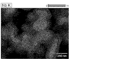
The sample obtained in Example 1 was mixed with 3% by mass of camphor and a niobium molded body was produced using an automatic element molding machine. The element was adjusted so that a niobium wire was planted in the center, the volume was about 20 mm 3 , and the molded body density was about 3.0 g / cm 3 . This element was placed in a vacuum sintering furnace and maintained at a maximum temperature of 1230 ° C. for 30 minutes at a vacuum of 10 −3 Pa or less to produce a sintered body. This sintered body was used as an anode, and a 1% by mass 90 ° C. phosphoric acid aqueous solution was used as an electrolyte, and anodization was performed at 20 V at a current density of 200 mA / g. After the voltage reached 20 V, the voltage was maintained at a constant voltage for 3 hours. A chemical conversion element (anode body) was produced. The anode body was washed with running water, dried, and subjected to various characteristic measurement tests. Table 2 shows electric characteristic values of the anode body. The anode body was cut and observed with a TEM (Transmission Electron Microscope). 1 to 4 show element distributions by EDX (Energy Dispersive X-ray spectrometry).
比較例4:
実施例2において、サンプルに比較例1で得られた造粒物を使用した以外は実施例2と同様の工程で陽極体を作製し、各種特性の測定試験に供した。この陽極体の電気特性値を表2に示す。Comparative Example 4:
In Example 2, an anode body was produced in the same process as in Example 2 except that the granulated product obtained in Comparative Example 1 was used as a sample, and subjected to measurement tests for various characteristics. Table 2 shows electric characteristic values of the anode body.
比較例5:
実施例2において、比較例2で得られた造粒物を使用した以外は実施例2と同様の工程で陽極体を作製し、各種特性測定試験に供した。この陽極体の電気特性値を表2に示す。陽極体を切断しTEM観察した。EDXによるによる元素分布を図5〜8に示す。Comparative Example 5:
In Example 2, an anode body was produced in the same process as in Example 2 except that the granulated product obtained in Comparative Example 2 was used, and subjected to various characteristic measurement tests. Table 2 shows electric characteristic values of the anode body. The anode body was cut and observed with TEM. The element distribution by EDX is shown in FIGS.
比較例6:
実施例2において、比較例3で得られた造粒物を使用した以外は実施例2と同様の工程で陽極体を作製し、各種試験に供した。Comparative Example 6:
In Example 2, an anode body was prepared in the same process as in Example 2 except that the granulated product obtained in Comparative Example 3 was used, and subjected to various tests.
表1の測定結果からわかるように実施例1、比較例2及び比較例3はアルミニウムが含有されているがその濃度は初期投入量の約半量である。これは工程中でアルミニウムが合金化しないもの、または脱離するものが約半量あることを示している。アルミニウム成分が存在することでニオブの表面拡散が阻害され、表面エネルギーが大きい状態で熱処理が終了するため、酸素濃度と比表面積は比較例1よりも大きい。粉体結着強度指数を見ると実施例1が大きくなっている。これはニオブ同士の融着のほかにニオブアルミニウム金属間化合物が接合助剤の役目を果たし、ニオブの表面拡散阻害分を差し引いても余りある効果を発揮していることを示す。比較例2はセラミックス成分がこの温度条件の熱処理では接合助剤として作用していないことを示す。比較例3はアルミニウムが均等に分布しているので接合助剤の役目を果たさないものと考えられる。 As can be seen from the measurement results in Table 1, Example 1, Comparative Example 2 and Comparative Example 3 contain aluminum, but the concentration is about half of the initial charge. This indicates that about half of the aluminum does not alloy or desorb during the process. The presence of the aluminum component inhibits the surface diffusion of niobium, and the heat treatment is completed with a large surface energy. Therefore, the oxygen concentration and the specific surface area are larger than those in Comparative Example 1. When looking at the powder binding strength index, Example 1 is larger. This indicates that in addition to the fusion of niobium, the niobium aluminum intermetallic compound serves as a bonding aid, and even if the surface diffusion inhibition amount of niobium is subtracted, the effect is much exhibited. Comparative Example 2 shows that the ceramic component does not act as a bonding aid in the heat treatment under this temperature condition. In Comparative Example 3, it is considered that aluminum does not serve as a bonding aid because aluminum is evenly distributed.
表2の測定結果からは、本発明の手法による実施例2は比較例4〜6よりも静電容量が大きいことがわかる。特筆すべき点はニオブコンデンサに特有の加熱後測定での容量増加率が実施例2では低く抑えられていることである。これは誘電体化成皮膜の不安定さの要因である酸化皮膜中を移動できる酸素が、アルミニウムでトラップされているためと考えられる。実施例2では化成皮膜中の移動できる酸素がもたらす部分である誘電体成分がもともと少ないので、誘電体が比較例4の化成皮膜よりも実効的に薄くなっているが、アルミニウムでトラップされる分だけ通常測定における静電容量が上昇する。比較例6はニオブ中にアルミニウムが均一に分布しているのでアルミニウム由来の誘電体成分も均一に生成しており、アルミニウム化成皮膜の誘電率はニオブ化成皮膜の誘電率よりも低いことから、アルミニウムによる静電容量の上昇が見られない。 From the measurement results in Table 2, it can be seen that Example 2 according to the method of the present invention has a larger capacitance than Comparative Examples 4-6. It should be noted that the rate of increase in capacity in the measurement after heating, which is characteristic of niobium capacitors, is kept low in Example 2. This is presumably because oxygen that can move in the oxide film, which is a factor of instability of the dielectric conversion film, is trapped by aluminum. In Example 2, the dielectric component, which is the part brought about by the movable oxygen in the chemical conversion film, is originally less, so the dielectric is effectively thinner than the chemical conversion film of Comparative Example 4, but the amount trapped by aluminum. Only the capacitance in normal measurement increases. In Comparative Example 6, since aluminum is uniformly distributed in niobium, a dielectric component derived from aluminum is also uniformly formed, and the dielectric constant of the aluminum conversion coating is lower than that of the niobium conversion coating. No increase in electrostatic capacity due to.
図1〜4と図5〜8はそれぞれ実施例2、比較例5の化成体を観察したものであり、図1及び図5は、それぞれ実施例2及び比較例5の化成素子断面の透過型電子顕微鏡(TEM)写真(×20万倍)であり、図2〜4は実施例2の化成素子断面のエネルギー分散型X線分析(EDX)による、それぞれNb Kα線、Al Kα線及びO Kα線の分布を示す写真(×20万倍)であり、図6〜8は比較例5の化成素子断面EDXによる、それぞれNb Kα線、Al Kα線及びO Kα線の分布を示す写真(×20万倍)である。
図1及び図5のSEM画像の縮尺スケールを用いて、化成皮膜の厚さを実測し、その値の5点の平均値を化成電圧で割り化成定数を算出すると、両者とも32Å/Vであり差は見られない。このことより両者の化成皮膜の厚みに差がないと言えるので、容量の増加は化成皮膜の厚さの変化に起因するものではないことがわかる。図2〜4と図6〜8を比較すると、実施例2の素子では誘電体層の表面にアルミニウム元素の局在部位が散在して存在するのに対し、比較例5の素子では分布状況がホワイトノイズレベルであると考えられ局在部位が見られない。さらに図の右部中央付近にアルミニウムの濃縮部分とニオブの欠落部分があることから、アルミナとして残留していることがわかる。また図2と図4、図6と図8との比較で、実施例2の素子は酸素分布が比較的均一であるのに対し、比較例5では化成皮膜部分に酸素の濃縮が顕著に見られる。この濃縮部分が化成皮膜中を移動できる酸素に起因すると考えられる。本発明の方法で作製された化成体ではアルミニウムが部分的に濃縮するにもかかわらず酸素は濃縮部が見られないことと、化成皮膜が従来法と比べて均一に生成することが特徴である。
1-4 and 5-8 respectively Example 2 is obtained by observing the conversion of Comparative Example 5, FIGS. 1 and 5, a transmission type of chemical element cross section of each of Example 2 and Comparative Example 5 It is an electron microscope (TEM) photograph (× 200,000 times), and FIGS. 2 to 4 are Nb K α ray, Al K α ray and Al K α ray obtained by energy dispersive X-ray analysis (EDX) of the cross section of the chemical conversion element of Example 2, respectively. 6 is a photograph (× 200,000 times) showing the distribution of O K α-rays, and FIGS. 6 to 8 are distributions of Nb K α-rays, Al K α-rays, and O K α-rays, respectively, according to the conversion element cross section EDX of Comparative Example 5. It is a photograph (× 200,000 times) showing.
Using the scale of the SEM images in FIGS. 1 and 5, the thickness of the chemical conversion film was measured, and the average value of the five values was divided by the conversion voltage to calculate the conversion constant, both of which were 32 Å / V. There is no difference. From this, it can be said that there is no difference between the thicknesses of the two conversion coatings, and thus it is understood that the increase in capacity is not caused by a change in the thickness of the conversion coating. Comparing FIGS. 2 to 4 and FIGS. 6 to 8, in the element of Example 2, the localized portion of the aluminum element is scattered on the surface of the dielectric layer, whereas in the element of Comparative Example 5, the distribution situation is It is considered to be a white noise level, and no localized part is seen. Furthermore, since there is an aluminum concentrated portion and a niobium missing portion near the center of the right part of the figure, it can be seen that it remains as alumina. In comparison between FIGS. 2 and 4 and FIGS. 6 and 8, the element of Example 2 has a relatively uniform oxygen distribution, whereas in Comparative Example 5, oxygen concentration is noticeably observed in the chemical conversion film portion. It is done. This concentrated portion is considered to be caused by oxygen that can move in the chemical conversion film. The chemical produced by the method of the present invention is characterized in that oxygen is not concentrated even though aluminum is partially concentrated, and that the chemical conversion film is formed more uniformly than the conventional method. .
Claims (10)
Applications Claiming Priority (3)
| Application Number | Priority Date | Filing Date | Title |
|---|---|---|---|
| JP2012284217 | 2012-12-27 | ||
| JP2012284217 | 2012-12-27 | ||
| PCT/JP2013/084850 WO2014104178A1 (en) | 2012-12-27 | 2013-12-26 | Chemical conversion body for niobium capacitor positive electrode, and production method therefor |
Publications (2)
| Publication Number | Publication Date |
|---|---|
| JPWO2014104178A1 JPWO2014104178A1 (en) | 2017-01-12 |
| JP6242814B2 true JP6242814B2 (en) | 2017-12-06 |
Family
ID=51021252
Family Applications (1)
| Application Number | Title | Priority Date | Filing Date |
|---|---|---|---|
| JP2014554538A Expired - Fee Related JP6242814B2 (en) | 2012-12-27 | 2013-12-26 | Niobium capacitor anode chemical and method for producing the same |
Country Status (5)
| Country | Link |
|---|---|
| US (1) | US20150340162A1 (en) |
| EP (1) | EP2939761B1 (en) |
| JP (1) | JP6242814B2 (en) |
| TW (1) | TW201446361A (en) |
| WO (1) | WO2014104178A1 (en) |
Families Citing this family (3)
| Publication number | Priority date | Publication date | Assignee | Title |
|---|---|---|---|---|
| CN104860267B (en) * | 2015-05-12 | 2017-05-17 | 昆明冶金研究院 | Ultrafine hydrogenated niobium powder preparation method |
| CN109439990A (en) * | 2018-12-29 | 2019-03-08 | 宁波高新区敦和科技有限公司 | A kind of preparation process of high-compactness high-content molybdenum niobium alloy target |
| CN112045191B (en) * | 2020-08-27 | 2021-10-01 | 中南大学 | Sintering method of aluminum electrolytic capacitor anode foil with uniformly dispersed slurry |
Family Cites Families (10)
| Publication number | Priority date | Publication date | Assignee | Title |
|---|---|---|---|---|
| JPS5539899B2 (en) | 1971-08-09 | 1980-10-14 | ||
| DE19953946A1 (en) * | 1999-11-09 | 2001-05-10 | Starck H C Gmbh Co Kg | Capacitor powder |
| KR100759290B1 (en) | 2000-08-10 | 2007-09-17 | 쇼와 덴코 가부시키가이샤 | Niobium alloy powder, sinter thereof, and capacitor employing the same |
| US6652619B2 (en) * | 2000-08-10 | 2003-11-25 | Showa Denko K.K. | Niobium powder, sintered body thereof, and capacitor using the same |
| US20030112577A1 (en) * | 2001-10-02 | 2003-06-19 | Showa Denko K.K. | Niobium particle, niobium sintered body, niobium formed body and niobium capacitor |
| US20060114644A1 (en) | 2002-11-18 | 2006-06-01 | Masana Imagumbai | Nb-a1 alloy powder for electrolytic capacitors, method for manufacturing nb-a1 alloy powder, and electrolytic capacitor |
| JP4178519B2 (en) | 2004-03-26 | 2008-11-12 | 日立エーアイシー株式会社 | Method for producing niobium alloy powder and sintered body for solid electrolytic capacitor |
| JP4452992B2 (en) * | 2004-03-26 | 2010-04-21 | 日立化成エレクトロニクス株式会社 | Manufacturing method of sintered body for solid electrolytic capacitor |
| US20060260437A1 (en) * | 2004-10-06 | 2006-11-23 | Showa Denko K.K. | Niobium powder, niobium granulated powder, niobium sintered body, capacitor and production method thereof |
| EP2312597A4 (en) * | 2008-07-29 | 2018-04-04 | Showa Denko K.K. | Method for manufacturing niobium solid electrolytic capacitor |
-
2013
- 2013-12-26 EP EP13869543.2A patent/EP2939761B1/en not_active Not-in-force
- 2013-12-26 JP JP2014554538A patent/JP6242814B2/en not_active Expired - Fee Related
- 2013-12-26 US US14/758,049 patent/US20150340162A1/en not_active Abandoned
- 2013-12-26 TW TW102148467A patent/TW201446361A/en unknown
- 2013-12-26 WO PCT/JP2013/084850 patent/WO2014104178A1/en active Application Filing
Also Published As
| Publication number | Publication date |
|---|---|
| EP2939761B1 (en) | 2019-02-27 |
| JPWO2014104178A1 (en) | 2017-01-12 |
| TW201446361A (en) | 2014-12-16 |
| WO2014104178A1 (en) | 2014-07-03 |
| EP2939761A4 (en) | 2016-08-24 |
| US20150340162A1 (en) | 2015-11-26 |
| EP2939761A1 (en) | 2015-11-04 |
Similar Documents
| Publication | Publication Date | Title |
|---|---|---|
| KR102546515B1 (en) | Anodes containing spherical powder and capacitors | |
| KR101629816B1 (en) | Process for Preparing Tantalum Powder for Capacitors | |
| JP5197369B2 (en) | A method of agglomerating and agglomerating metal particles | |
| JP5889086B2 (en) | Porous silicon particles and method for producing the same | |
| CZ300529B6 (en) | Pulverized tantalum, process of its preparation as well as anodes and capacitors produced therefrom | |
| JP2005035885A (en) | Niobium suboxide powder, niobium suboxide anode and solid-state electrolytic capacitor | |
| JP5547073B2 (en) | Process for preparing niobium suboxide or niobium powder | |
| JP6469650B2 (en) | Method for producing oxygen-poor valve metal sintered body with high surface area | |
| TW201937791A (en) | Silicon-based powder, electrode and battery comprising such a powder | |
| JP6242814B2 (en) | Niobium capacitor anode chemical and method for producing the same | |
| JP6412501B2 (en) | Method for producing niobium granulated powder | |
| JP2011082129A (en) | Hydrogen storage alloy for alkaline storage battery, and hydrogen storage alloy electrode for alkaline storage battery using the same | |
| JP6726798B2 (en) | Negative electrode for alkaline storage battery, manufacturing method thereof, and alkaline storage battery | |
| KR20220006079A (en) | Ti-Zr alloy powder and anode containing same | |
| JP2002030301A (en) | Nitrogen-containing metal powder, its production method porous sintered body using the same and solid electrolytic capacitor | |
| JP6258222B2 (en) | Niobium capacitor anode chemical and method for producing the same | |
| WO2015123851A1 (en) | Wet ball-milling method for tantalum powder and tantalum powder prepared therefrom | |
| JP2665928B2 (en) | Tantalum powder and method for producing the same | |
| JP2022519746A (en) | Niobium-tin compound powder for manufacturing superconducting parts | |
| JP2018100426A (en) | Method for producing metal granulated particles |
Legal Events
| Date | Code | Title | Description |
|---|---|---|---|
| A131 | Notification of reasons for refusal |
Free format text: JAPANESE INTERMEDIATE CODE: A131 Effective date: 20170818 |
|
| A521 | Request for written amendment filed |
Free format text: JAPANESE INTERMEDIATE CODE: A523 Effective date: 20171012 |
|
| TRDD | Decision of grant or rejection written | ||
| A01 | Written decision to grant a patent or to grant a registration (utility model) |
Free format text: JAPANESE INTERMEDIATE CODE: A01 Effective date: 20171027 |
|
| A61 | First payment of annual fees (during grant procedure) |
Free format text: JAPANESE INTERMEDIATE CODE: A61 Effective date: 20171108 |
|
| R150 | Certificate of patent or registration of utility model |
Ref document number: 6242814 Country of ref document: JP Free format text: JAPANESE INTERMEDIATE CODE: R150 |
|
| LAPS | Cancellation because of no payment of annual fees |