JP6242546B2 - Electronic equipment casing - Google Patents
Electronic equipment casing Download PDFInfo
- Publication number
- JP6242546B2 JP6242546B2 JP2017532290A JP2017532290A JP6242546B2 JP 6242546 B2 JP6242546 B2 JP 6242546B2 JP 2017532290 A JP2017532290 A JP 2017532290A JP 2017532290 A JP2017532290 A JP 2017532290A JP 6242546 B2 JP6242546 B2 JP 6242546B2
- Authority
- JP
- Japan
- Prior art keywords
- housing
- chassis
- opening
- sheet metal
- plate portion
- Prior art date
- Legal status (The legal status is an assumption and is not a legal conclusion. Google has not performed a legal analysis and makes no representation as to the accuracy of the status listed.)
- Active
Links
Images
Classifications
-
- H—ELECTRICITY
- H05—ELECTRIC TECHNIQUES NOT OTHERWISE PROVIDED FOR
- H05K—PRINTED CIRCUITS; CASINGS OR CONSTRUCTIONAL DETAILS OF ELECTRIC APPARATUS; MANUFACTURE OF ASSEMBLAGES OF ELECTRICAL COMPONENTS
- H05K7/00—Constructional details common to different types of electric apparatus
- H05K7/14—Mounting supporting structure in casing or on frame or rack
- H05K7/1401—Mounting supporting structure in casing or on frame or rack comprising clamping or extracting means
- H05K7/1411—Mounting supporting structure in casing or on frame or rack comprising clamping or extracting means for securing or extracting box-type drawers
- H05K7/1412—Mounting supporting structure in casing or on frame or rack comprising clamping or extracting means for securing or extracting box-type drawers hold down mechanisms, e.g. avionic racks
-
- H—ELECTRICITY
- H05—ELECTRIC TECHNIQUES NOT OTHERWISE PROVIDED FOR
- H05K—PRINTED CIRCUITS; CASINGS OR CONSTRUCTIONAL DETAILS OF ELECTRIC APPARATUS; MANUFACTURE OF ASSEMBLAGES OF ELECTRICAL COMPONENTS
- H05K7/00—Constructional details common to different types of electric apparatus
- H05K7/02—Arrangements of circuit components or wiring on supporting structure
- H05K7/04—Arrangements of circuit components or wiring on supporting structure on conductive chassis
-
- H—ELECTRICITY
- H05—ELECTRIC TECHNIQUES NOT OTHERWISE PROVIDED FOR
- H05K—PRINTED CIRCUITS; CASINGS OR CONSTRUCTIONAL DETAILS OF ELECTRIC APPARATUS; MANUFACTURE OF ASSEMBLAGES OF ELECTRICAL COMPONENTS
- H05K5/00—Casings, cabinets or drawers for electric apparatus
- H05K5/0004—Casings, cabinets or drawers for electric apparatus comprising several parts forming a closed casing
- H05K5/0013—Casings, cabinets or drawers for electric apparatus comprising several parts forming a closed casing assembled by resilient members
-
- H—ELECTRICITY
- H05—ELECTRIC TECHNIQUES NOT OTHERWISE PROVIDED FOR
- H05K—PRINTED CIRCUITS; CASINGS OR CONSTRUCTIONAL DETAILS OF ELECTRIC APPARATUS; MANUFACTURE OF ASSEMBLAGES OF ELECTRICAL COMPONENTS
- H05K7/00—Constructional details common to different types of electric apparatus
- H05K7/14—Mounting supporting structure in casing or on frame or rack
-
- H—ELECTRICITY
- H05—ELECTRIC TECHNIQUES NOT OTHERWISE PROVIDED FOR
- H05K—PRINTED CIRCUITS; CASINGS OR CONSTRUCTIONAL DETAILS OF ELECTRIC APPARATUS; MANUFACTURE OF ASSEMBLAGES OF ELECTRICAL COMPONENTS
- H05K9/00—Screening of apparatus or components against electric or magnetic fields
- H05K9/0007—Casings
- H05K9/0009—Casings with provisions to reduce EMI leakage through the joining parts
-
- H—ELECTRICITY
- H05—ELECTRIC TECHNIQUES NOT OTHERWISE PROVIDED FOR
- H05K—PRINTED CIRCUITS; CASINGS OR CONSTRUCTIONAL DETAILS OF ELECTRIC APPARATUS; MANUFACTURE OF ASSEMBLAGES OF ELECTRICAL COMPONENTS
- H05K9/00—Screening of apparatus or components against electric or magnetic fields
- H05K9/0007—Casings
- H05K9/0018—Casings with provisions to reduce aperture leakages in walls, e.g. terminals, connectors, cables
Description
この発明は、部品を保持する電子機器の筐体に関するものである。 The present invention relates to a housing of an electronic device that holds a component.
従来、電子機器の組立時には、筐体の内部底面にかしめ等により取り付けられた円筒状のポストを用いて、基板等の部品を筐体に固定していた。円筒状のポストの内周面には、雌ねじが形成されている。この円筒状のポストにねじ孔の形成された部品を載せ、両者をねじ止めすることにより、ポストを介して筐体に部品を固定する。しかし、筐体とは別体のポストを用いることで、部品点数及びコストの増加を招くという懸念があった。
これに対し、例えば特許文献1に記載の構成では、ポストを用いることなく基板を固定している。この引用文献1には、具体的に、板金フレームの一部を切り起こして折り曲げ、プリント基板取付部とする構成が記載されている。板金フレームに基板が直接取り付けられることで、基板の接地も可能となっている。そして、切り起こしにより板金フレームに開けられた孔は、外部からの異物の侵入口とも成り得るが、カバー部材により塞がれる構成となっている。Conventionally, when an electronic device is assembled, components such as a substrate are fixed to the casing using a cylindrical post attached to the inner bottom surface of the casing by caulking or the like. An internal thread is formed on the inner peripheral surface of the cylindrical post. A component having a screw hole is placed on the cylindrical post, and both are screwed to fix the component to the casing via the post. However, there is a concern that the use of a post separate from the housing causes an increase in the number of parts and the cost.
On the other hand, for example, in the configuration described in Patent Document 1, the substrate is fixed without using a post. Specifically, the cited document 1 describes a configuration in which a part of a sheet metal frame is cut and raised and bent to form a printed circuit board mounting portion. The substrate can be grounded by directly attaching the substrate to the sheet metal frame. The hole opened in the sheet metal frame by cutting and raising can be an entrance for foreign matter from the outside, but is configured to be closed by a cover member.
上記特許文献1に記載の構成は、ポストは不要となるものの、板金フレームの孔を塞ぐために専用のカバー部材を別に用意する必要があった。また、板金フレームと基板同士に加え、板金フレーム同士の電気的な導通を確保することでEMC(Electro Magnetic Compatibility)を強化できる余地があるが、そのためには導電性ガスケット等を用意し、板金フレームで挟んだ構成とすることが一般的に多い。
このように、EMCの強化及び異物対策のためには、専用の別部材を用意する必要があり、部品点数及びコストの増加につながるという課題があった。
また、上記特許文献1に記載の構成は、その構成上、板金フレームにカバー部材をはめた後に、プリント基板をプリント基板取付部にねじ止めすることとなる。従って、このカバー部材は、外部からの異物侵入の防止という点で効果的ではあるが、異物であるねじ締め時の金属くずを、外部へ排出させずに内部に留めてしまうものでもあった。In the configuration described in Patent Document 1, a post is not necessary, but a dedicated cover member has to be prepared separately in order to close the hole of the sheet metal frame. In addition to sheet metal frames and substrates, there is room for strengthening EMC (Electro Magnetic Compatibility) by ensuring electrical continuity between the sheet metal frames. For this purpose, a conductive gasket or the like is prepared and a sheet metal frame is prepared. Generally, the structure is sandwiched between.
Thus, in order to strengthen EMC and prevent foreign matters, it is necessary to prepare a separate member for exclusive use, resulting in an increase in the number of parts and cost.
Moreover, the structure of the said patent document 1 will screw a printed circuit board to a printed circuit board attachment part, after attaching a cover member to a sheet-metal frame on the structure. Therefore, this cover member is effective in terms of preventing the entry of foreign matter from the outside, but it also keeps the metal scrap at the time of screw fastening, which is a foreign matter, inside without being discharged to the outside.
この発明は、上記のような課題を解決するためになされたもので、ポストを設けなくても部品を固定でき、筐体を形成する部材同士の組付けによってEMCの強化及び異物対策を行うことができる電子機器の筐体を得ることを目的とする。 The present invention has been made to solve the above-described problems, and can fix parts without providing a post, and can strengthen EMC and prevent foreign matter by assembling members forming a casing. An object of the present invention is to obtain a housing for an electronic device that can be used.
この発明に係る電子機器の筐体は、開口部を形成して筐体内部側へ切り起こされ開口部に対向する位置に部品固定用のねじ孔が設けられた部品取付部を有する第1板金部材から成る基面と、一端が自由端として筐体内部側へ切り起こされた弾性片を有する板部及び板部から曲げられた側板部を有する第2板金部材の、側板部から成る側面とを備え、第2板金部材の板部は、第1板金部材に筐体外部側でオーバラップして開口部を塞ぐとともに、弾性片の自由端である端部が筐体外部側から内部側へ開口部を通って開口部の縁部に接触することを特徴とするものである。 A housing of an electronic device according to the present invention includes a first sheet metal having a component mounting portion that is formed with an opening, cut and raised to the inside of the housing, and provided with a screw hole for component fixing at a position facing the opening. A base surface composed of a member, and a side surface composed of a side plate portion of a second sheet metal member having a plate portion having an elastic piece cut and raised to the inside of the housing with one end as a free end and a side plate portion bent from the plate portion; The plate portion of the second sheet metal member overlaps the first sheet metal member on the outside of the housing to close the opening, and the end that is the free end of the elastic piece extends from the outside of the housing to the inside It contacts the edge of the opening through the opening.
この発明によれば、ポストを設けなくても部品を固定でき、筐体を形成する部材同士の組付けによってEMCの強化及び異物対策を行うことができる。 According to the present invention, parts can be fixed without providing a post, and EMC can be strengthened and foreign matter countermeasures can be taken by assembling members forming the casing.
以下、この発明をより詳細に説明するために、この発明を実施するための形態について、添付の図面に従って説明する。
実施の形態1.
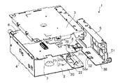
図1に、この発明の実施の形態1に係る電子機器の筐体1の分解斜視図を示す。筐体1は、例えばカーナビゲーション機器の筐体として使用される。筐体1は、ボトムシャーシ2とトップシャーシ3とフロントシャーシ4とリアシャーシ5とサイドシャーシ6とを有し、例えば基板7等の部品をその内部で保持する。筐体1の各シャーシは、例えば板金を適宜加工して作られる。Hereinafter, in order to explain the present invention in more detail, modes for carrying out the present invention will be described with reference to the accompanying drawings.
Embodiment 1 FIG.
FIG. 1 shows an exploded perspective view of a housing 1 of an electronic device according to Embodiment 1 of the present invention. The housing 1 is used as a housing of a car navigation device, for example. The casing 1 includes a
ボトムシャーシ2は、いわゆるZ曲げにより底板部20から筐体1の内部側へ切り起こされた部品取付部21を有する。部品取付部21は、開口部22の縁部から継ぎ目無くボトムシャーシ2の底板部20と一体で連続的に、筐体1の内部側へ略垂直に立ち上がる壁部21aと、壁部21aの先端部から継ぎ目無く壁部21aと一体で連続的に、底板部20に対し略平行に伸びる載置部21bとを有する。載置部21bには、バーリング加工及びタップ加工により、基板7等の部品固定用のねじ孔21cが形成されている。
部品取付部21を切り起こすことにより、ボトムシャーシ2には、開口部22が形成されている。ねじ孔21cは、開口部22に対向する。
ボトムシャーシ2は、筐体1の第1板金部材である。The
An
The
トップシャーシ3は、ボトムシャーシ2と対向して設けられる。
フロントシャーシ4及びサイドシャーシ6は、ボトムシャーシ2及びトップシャーシ3に対して略垂直に設けられる。なお、サイドシャーシ6は、ボトムシャーシ2及びフロントシャーシ4と略垂直に設けられ、互いに対向する一対のシャーシで構成されるが、そのうちの1つは不図示としている。フロントシャーシ4及びサイドシャーシ6は、例えば一枚の板金を折り曲げることで、ボトムシャーシ2と一体的に作られる。The top chassis 3 is provided to face the
The
リアシャーシ5は、フロントシャーシ4と対向して設けられる。リアシャーシ5は、ボトムシャーシ2の底板部20にオーバラップして組み付けられる板部50と、板部50から曲げられて略垂直に立ち上がる側板部51とを有する。板部50は、底板部20に対し、筐体1の外部側に組み付けられる。
板部50は、一部が筐体1の内部側に切り起こされることで、板部50から継ぎ目無く一体で連続的に筐体1の内部側に向けて伸びる弾性片52を有する。弾性片52は、一端が固定端として板部50に連結され、他端は自由端となっている。自由端である端部には、筐体1の外部側に向けて凸の突起部52aが設けられている。
リアシャーシ5は、筐体1の第2板金部材である。The rear chassis 5 is provided to face the
The
The rear chassis 5 is a second sheet metal member of the housing 1.
基板7は、ねじ8を用いてボトムシャーシ2に固定される。基板7には、ボトムシャーシ2に対して位置合わせがされた際に、部品取付部21のねじ孔21cと対向する孔70が形成されている。つまり、部品取付部21の載置部21bに基板7を置き、ねじ8を孔70に通してねじ孔21cに回し入れることで、基板7が固定される。
The
このように、部品取付部21を基板7等の部品の固定に用いることができるので、従来のようにボトムシャーシ2に円筒状のポストを取り付ける必要は無い。
また、ねじ締めの際に発生するねじ8の金属くずは、開口部22から筐体1の外部へ排出され、筐体1の内部に留まることがない。このため、ねじ締めの際に金属くずが発生しやすいがコストの低いタイプのねじを、ねじ8として採用することができる。
なお、ボトムシャーシ2には、板部50がオーバラップ可能な位置に、部品取付部21が必要に応じて複数個設けられており、基板7は、必要に応じて複数箇所でねじ8を用いて固定される。As described above, since the
Further, the metal scrap of the
The
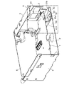
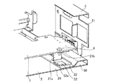
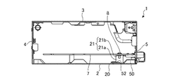
図2、図3及び図4は、図1に示す状態から基板7をねじ締めによりボトムシャーシ2に固定し、更にその後に、リアシャーシ5をボトムシャーシ2に組み付けたときの状態を示す図である。図2は一部破断斜視図、図3は図2中の部分Aを拡大して示す図である。図4は、図2中の方向Bから見た際の断面図である。図2では、トップシャーシ3を不図示とした。
2, 3, and 4 are views showing a state in which the
筐体1は、その基面がボトムシャーシ2から成り、基面に対する側面のうちの一面が、リアシャーシ5の側板部51から成る。側面は、基面と略垂直に交わる筐体1を構成する面の1つである。なお、図示例では、ボトムシャーシ2から成る基面を、筐体1の底面として機能させているが、図示例のようにボトムシャーシ2から成る基面を底面として用いる構成に限るものではない。つまり、箱形の筐体1を構成する各面のいずれを、ボトムシャーシ2から成る基面としてもよい。例えば、ボトムシャーシ2から成る基面を、筐体1の天面として機能させてもよい。
The base surface of the housing 1 is composed of the
リアシャーシ5は、弾性片52の自由端である端部が開口部22を筐体1の外部側から内部側へと通り、板部50が筐体1の外部側で底板部20にオーバラップする状態で、ボトムシャーシ2に組み付けられる。
リアシャーシ5がボトムシャーシ2に組み付けられると、側板部51から略垂直に継ぎ目無く一体で連続的に伸びる板部50により開口部22が塞がれる。これにより、開口部22を介して筐体1の内部へ異物が侵入するのを防ぐことができる。従来のように、開口部22を塞ぐために専用のカバー部材を別に用意する必要は無い。In the rear chassis 5, an end that is a free end of the
When the rear chassis 5 is assembled to the
また、リアシャーシ5がボトムシャーシ2に組み付けられると、開口部22を貫通した弾性片52は弾性変形して、突起部52aで開口部22の縁部にて底板部20と接触する。これにより、ボトムシャーシ2とリアシャーシ5との間で着実に導通を確保し、EMCを強化することができる。
なお、突起部52aを設けずに、弾性片52の端部と底板部20とを接触させてもよい。また、底板部20に突起部52aが嵌り込む凹部を設け、突起部52aをダボとして機能させることで、リアシャーシ5をボトムシャーシ2から抜けにくくすることができる。When the rear chassis 5 is assembled to the
In addition, you may make the edge part of the
上記では、弾性片52の自由端である端部が、筐体1の外部側から内部側へと開口部22を通り、板部50が、筐体1の外部側で開口部22を塞ぐ場合の構成を示した。つまり、リアシャーシ5の板部50が、ボトムシャーシ2の底板部20よりも外部側に組み付けられる構成の筐体への適用を想定した。しかしながら、リアシャーシ5の板部50が、ボトムシャーシ2の底板部20よりも内部側に組み付けられる構成の筐体であってもよい。この場合、弾性片52の自由端である端部が、筐体1の内部側から外部側へと開口部22を通り、板部50が、筐体1の内部側で開口部22を塞ぐ構成とすればよい。
In the above case, the end that is the free end of the
以上のように、この実施の形態1に係る電子機器の筐体1によれば、ボトムシャーシ2の底板部20から筐体1の内部側へ切り起こされた部品取付部21を用いて、基板7をねじ8で固定する。そして、部品取付部21により形成された開口部22は、リアシャーシ5を組み付けることにより塞がれ、弾性片52によりボトムシャーシ2とリアシャーシ5とが接触する。従って、ポストを設けなくても基板7等の部品を固定でき、また、別部材を新たに設けることなく、ボトムシャーシ2とリアシャーシ5の組付けによって、EMCの強化及び異物対策を行うことができる。これにより、部品点数の削減及びコスト削減が可能となる。また、電子機器の小サイズ化にも寄与する。
As described above, according to the casing 1 of the electronic device according to the first embodiment, the board is formed using the
また、弾性片52は、その端部に設けられた突起部52aで、開口部22の縁部に接触することとした。従って、より着実にボトムシャーシ2とリアシャーシ5とを接触させることができる。
In addition, the
なお、本願発明はその発明の範囲内において、実施の形態の任意の構成要素の変形、もしくは実施の形態の任意の構成要素の省略が可能である。 In the present invention, any constituent element of the embodiment can be modified or any constituent element of the embodiment can be omitted within the scope of the invention.
以上のように、この発明に係る電子機器の筐体は、ポストを設けなくても基板等の部品を固定でき、筐体を形成する部材同士の組付けによってEMCの強化及び異物対策を行うことができるので、カーナビゲーション機器等の筐体として用いるのに適している。 As described above, the casing of the electronic device according to the present invention can fix components such as a board without providing a post, and strengthens EMC and measures against foreign matters by assembling members forming the casing. Therefore, it is suitable for use as a housing of a car navigation device or the like.
1 筐体、2 ボトムシャーシ、3 トップシャーシ、4 フロントシャーシ、5 リアシャーシ、6 サイドシャーシ、7 基板、8 ねじ、20 底板部、21 部品取付部、21a 壁部、21b 載置部、21c ねじ孔、22 開口部、50 板部、51 側板部、52 弾性片、52a 突起部、70 孔。 DESCRIPTION OF SYMBOLS 1 Case, 2 Bottom chassis, 3 Top chassis, 4 Front chassis, 5 Rear chassis, 6 Side chassis, 7 Board, 8 Screw, 20 Bottom plate part, 21 Component attachment part, 21a Wall part, 21b Mounting part, 21c Screw Hole, 22 opening, 50 plate, 51 side plate, 52 elastic piece, 52a protrusion, 70 hole.
Claims (2)
一端が自由端として筐体内部側へ切り起こされた弾性片を有する板部及び前記板部から曲げられた側板部を有する第2板金部材の、前記側板部から成る側面とを備え、
前記第2板金部材の前記板部は、前記第1板金部材に筐体外部側でオーバラップして前記開口部を塞ぐとともに、前記弾性片の自由端である端部が筐体外部側から内部側へ前記開口部を通って前記開口部の縁部に接触することを特徴とする電子機器の筐体。A base surface made of a first sheet metal member having a component mounting portion formed with an opening to be cut and raised toward the inside of the housing and provided with a screw hole for fixing the component at a position facing the opening;
A plate part having an elastic piece cut and raised to the inside of the housing as one free end, and a second sheet metal member having a side plate part bent from the plate part, and a side surface comprising the side plate part,
The plate portion of the second sheet metal member overlaps the first sheet metal member on the outside of the housing to close the opening, and an end that is a free end of the elastic piece is formed from the outside of the housing. A housing of an electronic device, wherein the casing of the electronic device is in contact with an edge of the opening through the opening.
Applications Claiming Priority (1)
| Application Number | Priority Date | Filing Date | Title |
|---|---|---|---|
| PCT/JP2015/072036 WO2017022066A1 (en) | 2015-08-04 | 2015-08-04 | Casing of electronic device |
Publications (2)
| Publication Number | Publication Date |
|---|---|
| JPWO2017022066A1 JPWO2017022066A1 (en) | 2017-09-21 |
| JP6242546B2 true JP6242546B2 (en) | 2017-12-06 |
Family
ID=57942547
Family Applications (1)
| Application Number | Title | Priority Date | Filing Date |
|---|---|---|---|
| JP2017532290A Active JP6242546B2 (en) | 2015-08-04 | 2015-08-04 | Electronic equipment casing |
Country Status (5)
| Country | Link |
|---|---|
| US (1) | US10045454B2 (en) |
| JP (1) | JP6242546B2 (en) |
| CN (1) | CN107852834B (en) |
| DE (1) | DE112015006767T5 (en) |
| WO (1) | WO2017022066A1 (en) |
Families Citing this family (2)
| Publication number | Priority date | Publication date | Assignee | Title |
|---|---|---|---|---|
| CN111435261B (en) * | 2019-01-11 | 2023-01-10 | 纬联电子科技(中山)有限公司 | Fixing mechanism and related electronic equipment |
| JP2021057479A (en) * | 2019-09-30 | 2021-04-08 | ブラザー工業株式会社 | Power supply board enclosure and power supply unit |
Family Cites Families (18)
| Publication number | Priority date | Publication date | Assignee | Title |
|---|---|---|---|---|
| JPH0337251Y2 (en) * | 1986-03-17 | 1991-08-07 | ||
| JP2553883B2 (en) * | 1987-08-14 | 1996-11-13 | 株式会社 中西製作所 | Cooked rice mixing device |
| JPH01133782U (en) * | 1988-03-07 | 1989-09-12 | ||
| JP2553883Y2 (en) * | 1991-10-31 | 1997-11-12 | 株式会社ケンウッド | Chassis structure |
| JP3582079B2 (en) * | 1992-06-16 | 2004-10-27 | ソニー株式会社 | Chassis frame for electronic equipment |
| JPH1032394A (en) * | 1996-07-15 | 1998-02-03 | Sony Corp | Fixing chassis |
| TW572220U (en) * | 2003-01-08 | 2004-01-11 | Hannstar Display Corp | Liquid crystal display module and its fixing structure |
| US6876543B2 (en) * | 2003-03-07 | 2005-04-05 | Motorola, Inc. | Housing for a communication device and method assembling the same |
| JP4480082B2 (en) | 2005-01-14 | 2010-06-16 | 株式会社リコー | Printed circuit board holding device and printed circuit board holding method. |
| KR101385231B1 (en) * | 2006-08-24 | 2014-04-14 | 삼성디스플레이 주식회사 | Flat panel display |
| JP4770691B2 (en) * | 2006-10-13 | 2011-09-14 | パナソニック電工株式会社 | Case mating structure |
| US8101859B2 (en) * | 2008-01-03 | 2012-01-24 | Apple Inc. | Metal retaining features for handheld electronic device casing |
| CN201594955U (en) * | 2009-04-30 | 2010-09-29 | 比亚迪股份有限公司 | Casing assembling structure and casing with same |
| JP4937429B2 (en) * | 2010-01-25 | 2012-05-23 | 三菱電機株式会社 | Board fixing structure |
| JP5352532B2 (en) * | 2010-05-26 | 2013-11-27 | 株式会社日立製作所 | Circuit board mounting structure |
| JP2012052571A (en) * | 2010-08-31 | 2012-03-15 | Clarion Co Ltd | Navigation device, and assembly structure thereof |
| CN202679873U (en) * | 2012-06-08 | 2013-01-16 | Tcl光电科技(惠州)有限公司 | Circuit board fixing structure and display apparatus applying the circuit board fixing structure |
| CN104111699A (en) * | 2013-04-22 | 2014-10-22 | 鸿富锦精密工业(深圳)有限公司 | Fixing structure |
-
2015
- 2015-08-04 US US15/572,928 patent/US10045454B2/en active Active
- 2015-08-04 DE DE112015006767.1T patent/DE112015006767T5/en active Pending
- 2015-08-04 WO PCT/JP2015/072036 patent/WO2017022066A1/en active Application Filing
- 2015-08-04 JP JP2017532290A patent/JP6242546B2/en active Active
- 2015-08-04 CN CN201580081850.1A patent/CN107852834B/en active Active
Also Published As
| Publication number | Publication date |
|---|---|
| CN107852834B (en) | 2019-10-22 |
| CN107852834A (en) | 2018-03-27 |
| US20180160558A1 (en) | 2018-06-07 |
| WO2017022066A1 (en) | 2017-02-09 |
| DE112015006767T5 (en) | 2018-04-19 |
| US10045454B2 (en) | 2018-08-07 |
| JPWO2017022066A1 (en) | 2017-09-21 |
Similar Documents
| Publication | Publication Date | Title |
|---|---|---|
| JP2008235473A (en) | Electronic apparatus | |
| JP6242546B2 (en) | Electronic equipment casing | |
| JP6211030B2 (en) | Electronic control device and method of manufacturing electronic control device | |
| JP2005142215A (en) | Deformation preventing structure of cabinet lid | |
| JP6076217B2 (en) | Substrate fixing structure and electronic device to which the substrate fixing structure is applied | |
| WO2015022730A1 (en) | Electronic apparatus | |
| JPH11261254A (en) | Fitting structure for printed board | |
| JP2007194545A (en) | Housing of electrical appliance | |
| JP2004240018A (en) | Display positioning mechanism | |
| JP5848653B2 (en) | Electronic equipment | |
| JP6567079B2 (en) | Electronics | |
| US20120145723A1 (en) | Enclosure with mounting member | |
| JP2015046483A (en) | Waterproof housing | |
| JP2007165101A (en) | Electronic equipment equipped with antistatic function | |
| JP6043636B2 (en) | Electronic equipment | |
| JP2006234435A (en) | Portable electronic time piece | |
| JPWO2014109032A1 (en) | Electronics | |
| JP2007027304A (en) | Shield structure for electronic circuit | |
| JP2014154705A (en) | Connection structure by connector for substrate to substrate connection | |
| JP6469229B2 (en) | Chassis and board assembly structure and electronic equipment | |
| JP6096046B2 (en) | Electronics | |
| JP2006090949A (en) | Internal case of watt-hour meter | |
| JP5452786B2 (en) | Board assembly structure and electronic equipment | |
| JP5779881B2 (en) | Electronics | |
| JP2020031179A (en) | Component fixing structure and on-vehicle apparatus |
Legal Events
| Date | Code | Title | Description |
|---|---|---|---|
| A621 | Written request for application examination |
Free format text: JAPANESE INTERMEDIATE CODE: A621 Effective date: 20170703 |
|
| A871 | Explanation of circumstances concerning accelerated examination |
Free format text: JAPANESE INTERMEDIATE CODE: A871 Effective date: 20170703 |
|
| A975 | Report on accelerated examination |
Free format text: JAPANESE INTERMEDIATE CODE: A971005 Effective date: 20170926 |
|
| TRDD | Decision of grant or rejection written | ||
| A01 | Written decision to grant a patent or to grant a registration (utility model) |
Free format text: JAPANESE INTERMEDIATE CODE: A01 Effective date: 20171010 |
|
| A61 | First payment of annual fees (during grant procedure) |
Free format text: JAPANESE INTERMEDIATE CODE: A61 Effective date: 20171107 |
|
| R150 | Certificate of patent or registration of utility model |
Ref document number: 6242546 Country of ref document: JP Free format text: JAPANESE INTERMEDIATE CODE: R150 |
|
| R250 | Receipt of annual fees |
Free format text: JAPANESE INTERMEDIATE CODE: R250 |
|
| R250 | Receipt of annual fees |
Free format text: JAPANESE INTERMEDIATE CODE: R250 |
|
| R250 | Receipt of annual fees |
Free format text: JAPANESE INTERMEDIATE CODE: R250 |
|
| R250 | Receipt of annual fees |
Free format text: JAPANESE INTERMEDIATE CODE: R250 |