JP6241363B2 - Medium processing apparatus and medium storage cassette - Google Patents

Medium processing apparatus and medium storage cassette Download PDF

Info

Publication number
JP6241363B2
JP6241363B2 JP2014098649A JP2014098649A JP6241363B2 JP 6241363 B2 JP6241363 B2 JP 6241363B2 JP 2014098649 A JP2014098649 A JP 2014098649A JP 2014098649 A JP2014098649 A JP 2014098649A JP 6241363 B2 JP6241363 B2 JP 6241363B2
Authority
JP
Japan
Prior art keywords
storage cassette
slot
cassette
loading
protrusion
Prior art date
Legal status (The legal status is an assumption and is not a legal conclusion. Google has not performed a legal analysis and makes no representation as to the accuracy of the status listed.)
Active
Application number
JP2014098649A
Other languages
Japanese (ja)
Other versions
JP2015215791A (en
JP2015215791A5 (en
Inventor
小松 広和
広和 小松
亮輔 小嶋
亮輔 小嶋
由之 登坂
由之 登坂
Current Assignee (The listed assignees may be inaccurate. Google has not performed a legal analysis and makes no representation or warranty as to the accuracy of the list.)
Oki Electric Industry Co Ltd
Original Assignee
Oki Electric Industry Co Ltd
Priority date (The priority date is an assumption and is not a legal conclusion. Google has not performed a legal analysis and makes no representation as to the accuracy of the date listed.)
Filing date
Publication date
Application filed by Oki Electric Industry Co Ltd filed Critical Oki Electric Industry Co Ltd
Priority to JP2014098649A priority Critical patent/JP6241363B2/en
Priority to CN201580020944.8A priority patent/CN107111908B/en
Priority to PCT/JP2015/063382 priority patent/WO2015174352A1/en
Publication of JP2015215791A publication Critical patent/JP2015215791A/en
Publication of JP2015215791A5 publication Critical patent/JP2015215791A5/ja
Application granted granted Critical
Publication of JP6241363B2 publication Critical patent/JP6241363B2/en
Active legal-status Critical Current
Anticipated expiration legal-status Critical

Links

Images

Classifications

    • BPERFORMING OPERATIONS; TRANSPORTING
    • B65CONVEYING; PACKING; STORING; HANDLING THIN OR FILAMENTARY MATERIAL
    • B65HHANDLING THIN OR FILAMENTARY MATERIAL, e.g. SHEETS, WEBS, CABLES
    • B65H1/00Supports or magazines for piles from which articles are to be separated
    • B65H1/26Supports or magazines for piles from which articles are to be separated with auxiliary supports to facilitate introduction or renewal of the pile
    • BPERFORMING OPERATIONS; TRANSPORTING
    • B65CONVEYING; PACKING; STORING; HANDLING THIN OR FILAMENTARY MATERIAL
    • B65HHANDLING THIN OR FILAMENTARY MATERIAL, e.g. SHEETS, WEBS, CABLES
    • B65H83/00Combinations of piling and depiling operations, e.g. performed simultaneously, of interest apart from the single operation of piling or depiling as such
    • B65H83/02Combinations of piling and depiling operations, e.g. performed simultaneously, of interest apart from the single operation of piling or depiling as such performed on the same pile or stack
    • GPHYSICS
    • G07CHECKING-DEVICES
    • G07DHANDLING OF COINS OR VALUABLE PAPERS, e.g. TESTING, SORTING BY DENOMINATIONS, COUNTING, DISPENSING, CHANGING OR DEPOSITING
    • G07D9/00Counting coins; Handling of coins not provided for in the other groups of this subclass

Description

本発明は媒体処理装置及び媒体収納カセットに関し、例えば媒体として紙幣を扱う現金自動預払機に適用して好適なものである。   The present invention relates to a medium processing apparatus and a medium storage cassette, and is suitably applied to, for example, an automatic teller machine that handles banknotes as a medium.

従来、金融機関等で使用される現金自動預払機等においては、顧客との取引内容に応じて、例えば顧客に紙幣や硬貨等の現金を入金させ、また顧客へ現金を出金するものが広く普及している。   Conventionally, in an automatic teller machine used in a financial institution or the like, depending on the contents of a transaction with a customer, for example, the customer deposits cash such as banknotes and coins, and also withdraws cash to the customer. It is popular.

現金自動預払機としては、例えば顧客との間で紙幣の授受を行う紙幣入出金口と、投入された紙幣の金種、真偽及び正損を鑑別する鑑別部と、投入された紙幣を一時的に保留する一時保留部と、金種ごとに紙幣を収納する収納カセットとを有するものがある。   As an automatic teller machine, for example, a banknote deposit / withdrawal port for receiving and receiving banknotes with a customer, a discrimination unit for discriminating the denomination, authenticity and correctness of inserted banknotes, and temporarily inserting inserted banknotes There is one having a temporary holding part for temporarily holding and a storage cassette for storing banknotes for each denomination.

この現金自動預払機は、入金取引において、顧客が紙幣入出金口に紙幣を投入すると、投入された紙幣を鑑別部で鑑別し、正常紙幣と鑑別された紙幣を一時保留部で保留する一方、取引すべきでないと鑑別された紙幣を紙幣入出金口へ戻して顧客に返却する。続いて現金自動預払機は、顧客の操作指示により入金金額が確定されると、一時保留部に保留した紙幣の金種を鑑別部により再鑑別し、その金種に応じた収納カセットへ収納する。   This automatic teller machine, in a deposit transaction, when a customer inserts a banknote into a banknote deposit / withdrawal port, the inserted banknote is discriminated by a discrimination unit, and a banknote discriminated from a normal banknote is held in a temporary holding unit, The banknotes identified as not to be traded are returned to the banknote deposit / withdrawal port and returned to the customer. Subsequently, when the deposit amount is confirmed by the customer's operation instruction, the automatic teller machine re-discriminates the denomination of the banknote held in the temporary holding unit by the discrimination unit and stores it in the storage cassette corresponding to the denomination. .

また現金自動預払機のなかには、収納カセットに対する紙幣の補充作業や当該収納カセットからの紙幣の回収作業等の効率を高めるべく、本体に上下方向に沿った複数のスロットを有するカセット装填部を設け、カセット装填部の各スロットに対し収納カセットを1個ずつ装脱可能に構成したものがある。   In addition, in the automatic teller machine, in order to increase the efficiency of replenishment work of banknotes with respect to the storage cassette and collection work of banknotes from the storage cassette, a cassette loading unit having a plurality of slots along the vertical direction is provided in the main body, There is a configuration in which one storage cassette is detachable from each slot of the cassette loading unit.

ここで、仮にスロットの側面を装填後の収納カセットの最上面近傍まで形成してしまうと、当該収納カセットを装填又は取り外す際に、当該収納カセットを高い位置まで持ち上げる必要が生じるため、作業性の低下を招く。   Here, if the side surface of the slot is formed to the vicinity of the uppermost surface of the storage cassette after loading, it is necessary to lift the storage cassette to a high position when loading or removing the storage cassette. Incurs a decline.

そこで現金自動預払機のなかには、スロットにおける一部の側面を比較的低く、例えば通常の収納カセットが装填された場合の約半分までとすることにより、収納カセットを持ち上げるべき高さを低く抑え、その作業性を向上させるものも提案されている(例えば、特許文献1参照)。   Therefore, in some of the cash dispensers, a part of the side of the slot is relatively low, for example, up to about half of that when a normal storage cassette is loaded. Some have been proposed to improve workability (see, for example, Patent Document 1).

特開2011−118699号公報(第2図)JP 2011-118699 A (FIG. 2)

ところで、かかる現金自動預払機に対し、特に複数の国や地域の紙幣を取り扱う場合に、カセット装填部全体の大きさを変更すること無く、取り扱う紙幣の種類を増加させたい場合がある。そこで現金自動預払機のなかには、通常の収納カセットに対し高さを約半分に抑えた小型の収納カセットを用意し、この小型の収納カセットを1スロットに2段重ねて装填するようにしたものも提案されている。   By the way, especially when handling banknotes in a plurality of countries or regions, there are cases where it is desired to increase the types of banknotes handled without changing the size of the entire cassette loading unit. Therefore, some automatic teller machines have a small storage cassette that is about half the height of a normal storage cassette, and this small storage cassette is loaded in two layers in one slot. Proposed.

この現金自動預払機では、各スロットに通常の収納カセットを1個又は小型の収納カセットを2個装填することができるので、取り扱う紙幣の種類の数や各紙幣を収納しておきたい枚数に応じて、柔軟に構成を変更することが可能となる。   In this automatic teller machine, each slot can be loaded with one normal storage cassette or two small storage cassettes, so depending on the number of types of banknotes to be handled and the number of banknotes to be stored. Thus, the configuration can be changed flexibly.

また、一般に現金自動預払機では、各収納カセットの内部に紙幣を集積及び分離するための機構や、収納されている紙幣の量を検知するためのセンサ等が組み込まれている。そこで各収納カセット及びカセット装填部の各スロットには、当該収納カセットが当該カセット装填部に装填された際に互いに電気的に接続するための、複数の微小な端子を有するコネクタが設けられている。   Generally, in an automatic teller machine, a mechanism for collecting and separating banknotes in each storage cassette, a sensor for detecting the amount of banknotes stored, and the like are incorporated. Therefore, each slot of the storage cassette and the cassette loading unit is provided with a connector having a plurality of minute terminals for electrical connection to each other when the storage cassette is loaded in the cassette loading unit. .

しかしながら、特許文献1のようにスロットにおける一部の側面が低く構成された場合、小型の収納カセットを2段重ねる場合における上段側の収納カセットは、この低い側面により、下側部分のみが支持され、上側部分が支持されない。このため現金自動預払機では、当該スロットに対し小型の収納カセットが正しい位置に装填されていたとしても、外部から振動や衝撃が加えられると、スロット内で収納カセットが僅かに移動若しくは回転してしまい、互いのコネクタの嵌合を解除して電気的な接続が切断されてしまう、という問題があった。   However, when a part of the side surface in the slot is configured to be low as in Patent Document 1, only the lower side portion of the upper storage cassette is supported by the lower side surface when two small storage cassettes are stacked. The upper part is not supported. For this reason, even if a small storage cassette is loaded in the correct position in the automatic teller machine, if a vibration or impact is applied from the outside, the storage cassette moves or rotates slightly in the slot. As a result, there is a problem that the electrical connection is cut by releasing the mating of the connectors.

本発明は以上の点を考慮してなされたもので、スロットに対するカセットの装脱作業の容易さと装填した状態における位置精度の維持とを高い次元で両立し得る媒体処理装置及び媒体収納カセットを提案しようとするものである。   The present invention has been made in consideration of the above points, and proposes a medium processing apparatus and a medium storage cassette capable of achieving both high level of ease of loading and unloading of a cassette with respect to a slot and maintenance of positional accuracy in a loaded state. It is something to try.

かかる課題を解決するため本発明の媒体処理装置においては、内部に媒体を収納する収納カセットと、収納カセットが装填方向に沿って装填され、2以上の収納カセットが装填される場合には先装填収納カセットの後に後装填収納カセットが重ねて装填されるスロットとを備える媒体処理装置であって、装填方向を上下方向とし、スロットは、先装填収納カセットが装填される際に通過する範囲である先装填通過範囲の外に設けられ、後装填収納カセットを装填方向に沿って所定の後装填位置に案内する複数のスロット側ガイドと、先装填通過範囲の外に設けられ、後装填収納カセットとの間で電気的に接続するスロット側コネクタとを設け、後装填収納カセットは、スロットに装填される際に、複数のスロット側ガイドと接触して当該後装填収納カセットの装填姿勢が順次規制されるカセット側ガイドと、スロット内で後装填位置まで装填された際にスロット側コネクタと電気的に接続されるカセット側コネクタとを設けるようにした。 In order to solve such a problem, in the medium processing apparatus of the present invention, a storage cassette that stores a medium therein and a storage cassette that is loaded along the loading direction and two or more storage cassettes are loaded are preloaded. A medium processing apparatus including a slot in which a post-load storage cassette is stacked and loaded after the storage cassette, the loading direction being a vertical direction, and the slot is a range through which the pre-load storage cassette passes. A plurality of slot-side guides that are provided outside the pre-loading passage range and guide the post-loading storage cassette to a predetermined post-loading position along the loading direction; A slot-side connector electrically connected between the post-loading storage cassette and the post-loading storage cassette when the slot is loaded into contact with the plurality of slot-side guides. A cassette-side guide the loading orientation of the housing cassette is sequentially restricted, was provided a cassette side connector to be connected to the slot-side connector electrically when loaded to the rear loading position in the slot.

また本発明の媒体収納カセットにおいては、内部に媒体を収納し、所定のスロットに対し装填方向に沿って他の媒体収納カセットが装填された後に重ねて装填される媒体収納カセットであって、スロットに装填される際に、当該スロットにおいて他の媒体収納カセットが装填される際に通過する範囲である通過範囲の外に設けられた複数のスロット側ガイドと接触して当該媒体収納カセットの装填姿勢が順次規制されるカセット側ガイドとスロット内で所定位置まで案内された際に、スロットに設けられているスロット側コネクタと電気的に接続されるカセット側コネクタとを設け、装填方向を上下方向とするようにした。 The medium storage cassette according to the present invention is a medium storage cassette that stores a medium therein and is loaded in a stacked manner after another medium storage cassette is loaded in a loading direction in a predetermined slot. When the medium storage cassette is loaded, the loading position of the medium storage cassette comes into contact with a plurality of slot side guides provided outside the passing range, which is a range that passes when another medium storage cassette is loaded in the slot. Cassette side guides that are sequentially controlled, and cassette side connectors that are electrically connected to the slot side connectors provided in the slots when guided to a predetermined position within the slots, and the loading direction is the vertical direction I tried to do it.

本発明は、スロットに媒体収納カセットが装填された場合、当該媒体収納カセットの開口部側がスロットに支持されない状態となるものの、スロット側ガイドをカセット側ガイドに対し近接又は当接させるため、振動が加えられたとしても、その重心を中心とした回転を防止して、カセット側コネクタとスロット側コネクタとの嵌合を維持することができる。 In the present invention, when the medium storage cassette is loaded in the slot, the opening side of the medium storage cassette is not supported by the slot, but the slot side guide is brought close to or in contact with the cassette side guide. Even if added, the rotation around the center of gravity can be prevented, and the fitting between the cassette side connector and the slot side connector can be maintained.

本発明によれば、スロットに対するカセットの装脱作業の容易さと装填した状態における位置精度の維持とを高い次元で両立し得る媒体処理装置及び媒体収納カセットを実現できる。 ADVANTAGE OF THE INVENTION According to this invention , the medium processing apparatus and medium storage cassette which can be made compatible with the ease of the loading / unloading operation | work of the cassette with respect to a slot and the maintenance of the positional accuracy in the loaded state are realizable.

現金自動預払機の構成を示す略線的斜視図である。It is a rough-line perspective view which shows the structure of an automatic teller machine. 紙幣入出金機の構成を示す略線図である。It is a basic diagram which shows the structure of a banknote depositing / withdrawing machine. 下部ユニットの引き出しを示す略線図である。It is a basic diagram which shows drawer | drawing-out of a lower unit. 下部ユニットの構成を示す略線図である。It is a basic diagram which shows the structure of a lower unit. 装填部の構成を示す略線的斜視図である。It is a rough-line perspective view which shows the structure of a loading part. 装填部の構成を示す略線図である。It is a basic diagram which shows the structure of a loading part. 装填部の構成を示す略線的斜視図である。It is a rough-line perspective view which shows the structure of a loading part. 右ガイド体の構成を示す略線図である。It is a basic diagram which shows the structure of a right guide body. 左ガイド体の構成を示す略線図である。It is a basic diagram which shows the structure of a left guide body. 大収納カセットの構成を示す略線図である。It is a basic diagram which shows the structure of a large storage cassette. 下段小収納カセットの構成を示す略線図である。It is a basic diagram which shows the structure of a lower stage small storage cassette. 上段小収納カセットの構成を示す略線的斜視図である。It is a rough-line perspective view which shows the structure of an upper stage small storage cassette. 上段小収納カセットの外観構成を示す略線図である。It is a basic diagram which shows the external appearance structure of an upper stage small storage cassette. 上段小収納カセットの内部構成を示す略線図である。It is a basic diagram which shows the internal structure of an upper stage small storage cassette. 下段小収納カセットの上に上段小収納カセットを重ねた状態を示す略線図である。It is a basic diagram which shows the state which accumulated the upper stage small storage cassette on the lower stage small storage cassette. 上段小収納カセットのスロットへの装填(第1状態)を示す略線図である。It is a basic diagram which shows loading to the slot of an upper stage small storage cassette (1st state). 上段小収納カセットのスロットへの装填(第2状態)を示す略線図である。It is a basic diagram which shows loading to the slot of an upper stage small storage cassette (2nd state). 上段小収納カセットのスロットへの装填(第2状態)を示す略線図である。It is a basic diagram which shows loading to the slot of an upper stage small storage cassette (2nd state). 上段スロット側コネクタの破損を示す略線図である。It is an approximate line figure showing breakage of an upper slot side connector. 上段小収納カセットのスロットへの装填(第3状態)を示す略線図である。It is a basic diagram which shows loading to the slot of an upper stage small storage cassette (3rd state). 上段小収納カセットのスロットへの装填(第3状態)を示す略線図である。It is a basic diagram which shows loading to the slot of an upper stage small storage cassette (3rd state). スロット内における上段小収納カセットの回転を示す略線図である。It is a basic diagram which shows rotation of the upper stage small storage cassette in a slot. 上段小収納カセットのスロットへの装填(第4状態)を示す略線図である。It is a basic diagram which shows loading to the slot of an upper stage small storage cassette (4th state). 上段小収納カセットのスロットへの装填(第4状態)を示す略線図である。It is a basic diagram which shows loading to the slot of an upper stage small storage cassette (4th state). 上段小収納カセットのスロットへの装填(第5状態)を示す略線図である。It is a basic diagram which shows loading to the slot of an upper stage small storage cassette (5th state). 上段小収納カセットの回転ずれによるコネクタの破損を示す略線図である。It is a basic diagram which shows the damage of the connector by the rotation shift | offset | difference of an upper stage small storage cassette. スロットに対する上段小収納カセットの装填を示す略線図である。It is a basic diagram which shows loading of the upper stage small storage cassette with respect to a slot. 上段小収納カセットの回転ずれによるコネクタの破損を示す略線図である。It is a basic diagram which shows the damage of the connector by the rotation shift | offset | difference of an upper stage small storage cassette. 仮想的な下部ユニットにおける上段小収納カセットの回転(1)を示す略線図である。It is a basic diagram which shows rotation (1) of the upper stage small storage cassette in a virtual lower unit. 仮想的な下部ユニットにおける上段小収納カセットの回転(2)を示す略線図である。It is a basic diagram which shows rotation (2) of the upper stage small storage cassette in a virtual lower unit. 実施の形態による下部ユニットにおける上段小収納カセットの回転防止を示す略線図である。It is a basic diagram which shows rotation prevention of the upper stage small storage cassette in the lower unit by embodiment. 他の実施の形態による右ガイド体及び突起の構成を示す略線図である。It is a basic diagram which shows the structure of the right guide body and protrusion by other embodiment. 他の実施の形態による上段小収納カセットのスロットへの装填(第3状態)を示す略線図である。It is a basic diagram which shows the loading (3rd state) to the slot of the upper stage small storage cassette by other embodiment. 他の実施の形態による右前下突起の構成を示す略線図である。It is a basic diagram which shows the structure of the right front lower protrusion by other embodiment. 他の実施の形態による右前下突起の構成を示す略線図である。It is a basic diagram which shows the structure of the right front lower protrusion by other embodiment.

以下、発明を実施するための形態(以下実施の形態とする)について、図面を用いて説明する。   Hereinafter, modes for carrying out the invention (hereinafter referred to as embodiments) will be described with reference to the drawings.

[1.現金自動預払機の構成]
図1に外観を示すように、現金自動預払機1は、箱状の筐体2を中心に構成されており、例えば金融機関等に設置され、顧客との間で入金取引や出金取引等の現金に関する取引を行う。
[1. Automatic teller machine configuration]
As shown in FIG. 1, the automatic teller machine 1 is configured with a box-shaped housing 2 as the center, and is installed in a financial institution, for example, for a deposit transaction or a withdrawal transaction with a customer. Transactions related to cash.

筐体2は、その前側に顧客が対峙した状態で紙幣の投入やタッチパネルによる操作等をしやすい箇所に接客部3が設けられている。接客部3は、カード入出口4、入出金口5、操作表示部6、テンキー7、及びレシート発行口8が設けられており、顧客との間で現金や通帳等を直接やり取りすると共に、取引に関する情報の通知や操作指示の受付を行う。   The housing 2 is provided with a customer service section 3 at a position where it is easy to insert bills or operate with a touch panel while the customer faces the front side. The customer service section 3 is provided with a card entry / exit 4, a deposit / withdrawal port 5, an operation display unit 6, a numeric keypad 7, and a receipt issuance port 8. Information notification and operation instructions are received.

カード入出口4は、キャッシュカード等の各種カードが挿入または排出される部分である。カード入出口4の筐体内側には、各種カードに磁気記録された口座番号等の読み取りを行うカード処理部(図示せず)が設けられている。入出金口5は、顧客により入金する紙幣が投入されると共に、顧客へ出金する紙幣が排出される部分である。また入出金口5は、シャッタを駆動することにより開放又は閉塞するようになっている。   The card entry / exit 4 is a portion into which various cards such as a cash card are inserted or ejected. A card processing unit (not shown) for reading account numbers and the like magnetically recorded on various cards is provided inside the housing of the card slot 4. The deposit / withdrawal port 5 is a portion where banknotes to be deposited by the customer are input and banknotes to be dispensed to the customer are discharged. The deposit / withdrawal port 5 is opened or closed by driving a shutter.

操作表示部6は、取引に際して操作画面を表示するLCD(Liquid Crystal Display)と、取引の種類の選択、暗証番号や取引金額等を入力するタッチパネルとが一体化されている。テンキー7は、「0」〜「9」の数字等の入力を受け付ける物理キーであり、暗証番号や取引金額等の入力操作時に用いられる。レシート発行口8は、取引処理の終了時に取引内容等を印字したレシートを発行する部分である。因みにレシート発行口8より筐体内側には、レシートに取引内容等を印字するレシート処理部(図示せず)が設けられている。   The operation display unit 6 is integrated with an LCD (Liquid Crystal Display) that displays an operation screen at the time of transaction and a touch panel for selecting a transaction type, inputting a personal identification number, transaction amount, and the like. The numeric keypad 7 is a physical key that accepts input of numbers such as “0” to “9”, and is used when an input operation such as a password or transaction amount is performed. The receipt issuing port 8 is a part that issues a receipt on which transaction details are printed at the end of transaction processing. Incidentally, a receipt processing unit (not shown) for printing transaction contents and the like on the receipt is provided inside the housing from the receipt issuing port 8.

以下では、現金自動預払機1のうち顧客が対峙する側を前側とし、その反対を後側とし、当該前側に対峙した顧客から見て左及び右をそれぞれ左側及び右側とし、さらに上側及び下側を定義して説明する。   In the following, the side of the automated teller machine 1 facing the customer is the front side, the opposite is the rear side, the left and right are the left side and the right side as viewed from the customer facing the front side, and the upper side and the lower side. Is defined and explained.

因みに筐体2は、前面を覆う前扉及び後面を覆う後扉(図示せず)がそれぞれ開閉可能に構成されている。すなわち筐体2は、顧客との間で現金に関する取引を行う取引動作時には、前扉等を閉塞することにより、内部に保有している紙幣や硬貨等を保護する。一方筐体2は、金融機関の職員や作業者等が保守作業や紙幣の補充・回収作業等を行う作業時には、必要に応じて前扉等を開放することにより、内部の各部に対する作業を容易に行わせることができる。   Incidentally, the housing 2 is configured such that a front door that covers the front surface and a rear door (not shown) that covers the rear surface can be opened and closed. That is, the housing | casing 2 protects the banknote, coin, etc. which are hold | maintained by obstruct | occluding a front door etc. at the time of the transaction operation | movement which performs the transaction regarding cash with a customer. On the other hand, the housing 2 is easy to work on each part by opening the front door etc. as necessary when a financial institution staff or worker performs maintenance work or banknote replenishment / collection work. Can be done.

筐体2内には、現金自動預払機1全体を統括制御する主制御部9や、紙幣に関する種々の処理を行う紙幣入出金機10等が設けられている。   In the housing 2, a main control unit 9 that performs overall control of the entire automatic teller machine 1, a banknote depositing and dispensing machine 10 that performs various processes related to banknotes, and the like are provided.

主制御部9は、図示しないCPU(Central Processing Unit)を中心に構成されており、図示しないROM(Read Only Memory)やフラッシュメモリ等から所定のプログラムを読み出して実行することにより、入金取引や出金取引等の種々の処理を行う。また主制御部9は、内部にRAM(Random Access Memory)、ハードディスクドライブやフラッシュメモリ等でなる記憶部9Aを有しており、この記憶部9Aに種々の情報を記憶させる。   The main control unit 9 is mainly configured by a CPU (Central Processing Unit) (not shown), and reads and executes a predetermined program from a ROM (Read Only Memory), a flash memory, etc. (not shown), thereby performing a deposit transaction and a withdrawal. Various processes such as gold transactions are performed. The main control unit 9 includes a storage unit 9A including a RAM (Random Access Memory), a hard disk drive, a flash memory, and the like, and stores various information in the storage unit 9A.

[2.紙幣入出金機の構成]
紙幣入出金機10は、図2に模式的な側面図を示すように、紙幣入出金機筐体11の内部に紙幣の入金処理や出金処理に関する種々の機構が設けられている。紙幣入出金機10の各部分は、紙幣制御部12により制御される。
[2. Configuration of banknote deposit and withdrawal machine]
As shown in the schematic side view of FIG. 2, the bill depositing / dispensing machine 10 is provided with various mechanisms related to bill depositing and dispensing processes inside the bill depositing / dispensing machine housing 11. Each part of the bill depositing / dispensing machine 10 is controlled by the bill control unit 12.

紙幣制御部12は、主制御部9と同様、図示しないCPUを中心に構成されており、図示しないROMやフラッシュメモリ等から所定のプログラムを読み出して実行し、また主制御部9などの他の制御部と連携することにより、紙幣の入金処理や出金処理等、紙幣に関する種々の処理を制御する。また紙幣制御部12は、内部にRAM及びフラッシュメモリ等でなる記憶部12A(図1)を有しており、この記憶部12Aに種々の情報を記憶させている。   As with the main control unit 9, the banknote control unit 12 is mainly configured by a CPU (not shown), reads out and executes a predetermined program from a ROM, a flash memory, etc. (not shown), and other main control unit 9 and the like. By cooperating with the control unit, various processes related to banknotes such as banknote depositing and dispensing processes are controlled. Moreover, the banknote control part 12 has the memory | storage part 12A (FIG. 1) which consists of RAM, flash memory, etc. inside, and memorize | stores various information in this memory | storage part 12A.

例えば顧客が現金自動預払機1との間で入金取引を行う場合、紙幣制御部12は、主制御部9等と連携しながら、操作表示部6を介して所定の操作入力を受け付けた後、入出金口5(図1)のシャッタを開いて入出金部13内へ紙幣を投入させる。   For example, when a customer performs a deposit transaction with the automatic teller machine 1, the banknote control unit 12 receives a predetermined operation input via the operation display unit 6 in cooperation with the main control unit 9 and the like. The shutter of the deposit / withdrawal port 5 (FIG. 1) is opened, and a bill is inserted into the deposit / withdrawal unit 13.

入出金部13は、紙幣が投入されると、入出金口5のシャッタを閉じてから紙幣を1枚ずつ取り出し、搬送部14へ受け渡す。搬送部14は、紙幣入出金機10内で紙幣を各部へ搬送し得るようになっており、受け渡された紙幣を短辺方向に沿って進行させ、鑑別部15へ搬送する。鑑別部15は、その内部で紙幣を搬送しながら当該紙幣の金種及び真偽、並びに損傷の程度等を鑑別し、その鑑別結果を紙幣制御部12へ通知する。これに応じて紙幣制御部12は、取得した鑑別結果に基づいて当該紙幣の搬送先を決定する。   When a banknote is inserted, the deposit / withdrawal unit 13 closes the shutter of the deposit / withdrawal port 5 and then removes the banknotes one by one and delivers them to the transport unit 14. The conveyance part 14 can convey a banknote to each part in the banknote depositing / withdrawing machine 10, advances the banknote passed along the short side direction, and conveys it to the discrimination part 15. The discrimination unit 15 discriminates the denomination and authenticity of the banknote and the degree of damage while conveying the banknote, and notifies the banknote control unit 12 of the discrimination result. In response to this, the banknote control unit 12 determines the transport destination of the banknote based on the acquired discrimination result.

このとき搬送部14は、鑑別部15において正常と鑑別された紙幣(いわゆる正券)を一時保留部16へ搬送する等して一時的に保留させる一方、取引すべきでないと鑑別された紙幣(いわゆる損券や偽券等)を入出金部13へ搬送して顧客に返却する。   At this time, the transport unit 14 temporarily holds the banknotes (so-called correct bills) identified as normal in the discrimination unit 15 by transporting them to the temporary storage unit 16 and the banknotes identified as not to be traded ( A so-called non-conformity ticket or fake ticket) is conveyed to the deposit / withdrawal unit 13 and returned to the customer.

その後紙幣制御部12は、操作表示部6(図1)を介して顧客に入金金額を確定させ、一時保留部16に保留している紙幣を鑑別部15へ搬送させてその金種及び損傷の程度等を鑑別させ、その鑑別結果を取得する。そして紙幣制御部12は、紙幣の損傷の程度が大きければ、これを再利用すべきでないリジェクト紙幣としてリジェクト庫17へ搬送して収納させ、損傷の程度が小さければ、これを再利用すべき紙幣として下搬送部18へ搬送させる。下搬送部18は、紙幣を前後方向へ搬送すると共に、その金種に応じた収納カセット19に振り分けて受け渡す。収納カセット19は、受け渡された紙幣を内部に集積して収納する。   Thereafter, the banknote control unit 12 allows the customer to confirm the deposit amount via the operation display unit 6 (FIG. 1), conveys the banknotes held in the temporary storage unit 16 to the discrimination unit 15, and denominations and damages thereof. Differentiate the degree, etc., and obtain the result of the discrimination. And the banknote control part 12 will convey this to the rejection store | warehouse | chamber 17 as a reject banknote which should not be reused if the degree of damage of a banknote is large, and if this is small, the banknote which should be reused As shown in FIG. The lower transport unit 18 transports the banknotes in the front-rear direction, and distributes them to the storage cassette 19 corresponding to the denomination. The storage cassette 19 accumulates and stores the delivered banknotes inside.

一方、例えば顧客が現金自動預払機1との間で出金取引を行う場合、紙幣制御部12は、主制御部9等と連携しながら、操作表示部6(図1)を介して所定の操作入力を受け付けた後、出金すべき金額に応じた紙幣を収納カセット19から繰り出させる。続いて紙幣制御部12は、この紙幣を下搬送部18及び搬送部14により鑑別部15へ搬送して鑑別させた上で入出金部13へ搬送し、入出金口5(図1)のシャッタを開いてこの紙幣を顧客に取り出させる。   On the other hand, for example, when a customer conducts a withdrawal transaction with the automatic teller machine 1, the banknote control unit 12 is linked with the main control unit 9 and the like via the operation display unit 6 (FIG. 1). After accepting the operation input, banknotes corresponding to the amount to be withdrawn are drawn out from the storage cassette 19. Subsequently, the banknote control unit 12 conveys the banknote to the discrimination unit 15 by the lower conveyance unit 18 and the conveyance unit 14, and then conveys the bill to the deposit / withdrawal unit 13, and the shutter of the deposit / withdrawal port 5 (FIG. 1). Open and let the customer pick up this bill.

このように紙幣入出金機10では、顧客から入金された紙幣を下搬送部18により振り分けて収納カセット19に収納し、また収納カセット19から紙幣を繰り出して顧客へ出金するようになっている。   Thus, in the banknote depositing / dispensing machine 10, the banknotes deposited from the customer are sorted by the lower transport unit 18 and stored in the storage cassette 19, and the banknotes are fed out from the storage cassette 19 to be withdrawn to the customer. .

[3.下部ユニットの構成]
ところで下搬送部18及び収納カセット19は、紙幣入出金機10の下側を占める下部ユニット21に組み込まれている。下部ユニット21は、図3に示すように、紙幣入出金機筐体11の下側部分に形成された下部筐体11Aに対し、前後方向に伸縮するスライドレール22を介して、前後方向へ移動可能に取り付けられている。このため下部ユニット21は、下部筐体11A内に収納された状態(図2)から後方へ移動されると当該下部筐体11Aから引き出された状態(図3)となり、またこの状態から前方へ移動されると再び収納された状態(図2)へ戻る。
[3. Configuration of lower unit]
By the way, the lower conveyance part 18 and the storage cassette 19 are integrated in the lower unit 21 which occupies the lower side of the banknote depositing / dispensing machine 10. As shown in FIG. 3, the lower unit 21 moves in the front-rear direction via a slide rail 22 that expands and contracts in the front-rear direction with respect to the lower case 11 </ b> A formed in the lower part of the bill depositing / dispensing machine case 11. It is attached as possible. Therefore, when the lower unit 21 is moved rearward from the state housed in the lower housing 11A (FIG. 2), the lower unit 21 is pulled out from the lower housing 11A (FIG. 3). When it is moved, it returns to the stored state (FIG. 2).

下部ユニット21は、図4(A)に示すように、全体として前後方向に長い直方体状に形成されており、大きく分けて下側の装填部25と上側の蓋体部26とにより構成されている。   As shown in FIG. 4A, the lower unit 21 is formed in a rectangular parallelepiped shape that is long in the front-rear direction as a whole, and is roughly composed of a lower loading portion 25 and an upper lid portion 26. Yes.

装填部25は、前後両側面、右側面、左側面の下側及び底面が閉塞されると共に、上面及び左側面の上側が開放されることにより、内部に収納カセット19(図2)を装填する空間を形成すると共に、上側面に内部空間と外部とを連通させる開口部を形成している。   The loading unit 25 is loaded with the storage cassette 19 (FIG. 2) by closing the front and rear side surfaces, the right side surface, the lower side and the bottom side of the left side, and opening the upper side of the top and left sides. While forming space, the opening part which connects internal space and the exterior is formed in the upper surface.

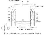
この装填部25は、図4(B)に示すように、その内部に前後方向に並ぶ5箇所のスロット28が形成されている。各スロット28は、装填方向としての上下方向に細長い直方体状に形成されており、それぞれ収納カセット19を装填し得るようになっている。   As shown in FIG. 4B, the loading unit 25 has five slots 28 arranged in the front-rear direction. Each slot 28 is formed in an elongated rectangular parallelepiped shape as the loading direction, and can be loaded with the storage cassette 19.

ここで各スロット28に装填し得る収納カセット19としては、比較的大きい大収納カセット19Aと、比較的小さい下段小収納カセット19Bと、同様に比較的小さい上段小収納カセット19Cとの3種類が用意されている。このうち先装填収納カセットとしての下段小収納カセット19B及び後装填収納カセットとしての上段小収納カセット19Cは、大収納カセット19Aと比較して、前後方向及び左右方向の長さがほぼ同等であるものの、上下方向の長さが約半分となっている。このため各スロット28は、1個の大収納カセット19Aを装填でき、或いは下段小収納カセット19Bの上に上段小収納カセット19Cを重ねた状態で、2個の収納カセット19を装填できる。   Here, there are three types of storage cassettes 19 that can be loaded into the slots 28: a relatively large storage cassette 19A, a relatively small lower stage small storage cassette 19B, and a relatively small upper stage small storage cassette 19C. Has been. Of these, the lower small storage cassette 19B as the pre-loading storage cassette and the upper small storage cassette 19C as the post-loading storage cassette have substantially the same length in the front-rear direction and the left-right direction compared to the large storage cassette 19A. The vertical length is about half. Therefore, each slot 28 can be loaded with one large storage cassette 19A, or can be loaded with two storage cassettes 19 with the upper small storage cassette 19C overlaid on the lower small storage cassette 19B.

蓋体部26(図4(A))は、全体として上下に薄い直方体状に構成されており、内部に下搬送部18(図2)が組み込まれている。また蓋体部26は、収納カセット19と対向する下面側(以下この面をカセット対向面とも呼ぶ)に、各収納カセット19との間で紙幣をそれぞれ受け渡す複数の受渡口26Aが形成されている。各受渡口26Aにおける長手方向の両端近傍には、収納カセット19との間で位置を合わせるための短い突起26APがそれぞれ立設されている。   The lid part 26 (FIG. 4A) is formed in a thin rectangular parallelepiped shape as a whole, and the lower transport part 18 (FIG. 2) is incorporated therein. Further, the lid portion 26 has a plurality of delivery ports 26 </ b> A for delivering banknotes to and from each storage cassette 19 on the lower surface side (hereinafter also referred to as a cassette facing surface) facing the storage cassette 19. Yes. Short projections 26AP for positioning with the storage cassette 19 are provided in the vicinity of both ends in the longitudinal direction of each delivery port 26A.

さらに蓋体部26は、装填部25に対し蝶番27を介して回動可能に取り付けられている。すなわち蓋体部26は、蝶番27を中心に回動することにより、図2に示したようにカセット対向面を下方向に向け装填部25の開口部を閉塞する閉塞状態、または図4(A)に示したように閉塞状態から約90度回動し、カセット対向面を左方向に向け当該開口部を開放した開放状態(詳しくは後述する)に遷移することができる。   Further, the lid part 26 is attached to the loading part 25 via a hinge 27 so as to be rotatable. That is, the lid part 26 rotates around the hinge 27 to close the opening of the loading part 25 with the cassette facing surface facing downward as shown in FIG. 2, or FIG. As shown in (), it can be rotated about 90 degrees from the closed state, and the cassette facing surface can be turned to the left, and the state can be changed to an open state (details will be described later).

[4.装填部の構成]
装填部25は、図5に斜視図を示すように、底部31、右側部32、左側部33、前側板34及び後側板35により囲まれる直方体状の空間を、前後方向に所定の間隔を隔てるように配置された4枚の仕切板36によって仕切ることで、上下方向に細長い5箇所のスロット28を形成している。
[4. Configuration of loading unit]
As shown in the perspective view of FIG. 5, the loading portion 25 divides a rectangular parallelepiped space surrounded by the bottom portion 31, the right side portion 32, the left side portion 33, the front side plate 34 and the rear side plate 35 in the front-rear direction. By partitioning with four partition plates 36 arranged in this manner, five slots 28 elongated in the vertical direction are formed.

各スロット28における下端、すなわち底部31の上面側には、下段スロット側コネクタ37が設けられている。この下段スロット側コネクタ37には、電力を供給し、また各種電気信号を伝達するための複数の接続端子(図示せず)が上方に向けて立設されている。   A lower slot side connector 37 is provided on the lower end of each slot 28, that is, on the upper surface side of the bottom portion 31. The lower slot side connector 37 is provided with a plurality of connection terminals (not shown) for supplying electric power and transmitting various electric signals upward.

右側部32は、交差方向としての左右方向に厚みを有する板状に形成されている。この右側部32における上下方向の長さは、比較的長くなっており、大収納カセット19Aにおける上下方向の長さとほぼ同等となっている。また右側部32は、上側の約半分の範囲において内側の一部分が抉られることにより、段差が形成されている。このためスロット28は、図6に示すように、下半分と比較して上半分が右側に突出した形となっている。   The right side portion 32 is formed in a plate shape having a thickness in the left-right direction as the intersecting direction. The length of the right side portion 32 in the vertical direction is relatively long, and is substantially equal to the length of the large storage cassette 19A in the vertical direction. In addition, the right side portion 32 is formed with a step by turning a part of the inner side in the upper half range. Therefore, as shown in FIG. 6, the slot 28 has a shape in which the upper half protrudes to the right as compared with the lower half.

また装填部25を左上方から見下ろした様子を表す図7(A)に示すように、右側部32における段差部分の上面には、スロット28ごとに、上段スロット側コネクタ38が設けられている。この上段スロット側コネクタ38には、下段スロット側コネクタ37と同様、電力を供給し、また各種電気信号を伝達するための複数の接続端子(図示せず)が上方に向けて立設されている。   Further, as shown in FIG. 7A showing a state where the loading unit 25 is looked down from the upper left, an upper slot side connector 38 is provided for each slot 28 on the upper surface of the step portion in the right side portion 32. As with the lower slot connector 37, the upper slot connector 38 is provided with a plurality of connection terminals (not shown) for supplying electric power and transmitting various electric signals upward. .

さらに右側部32の内側上段における各スロット28同士の境界部分、すなわち仕切板36の右上方であって、開口部33Hと反対側には、右ガイド体39がそれぞれ設けられている。右ガイド体39は、図8(A)に拡大した斜視図を示すと共に図8(B)に3面図を示すように、全体として上下方向に細長い直方体状の部材における前後両面に、上下方向に沿った溝がそれぞれ形成されている。また右ガイド体39は、前後方向に関し対称に形成されている。このため以下では、前側を中心に説明し、後側についての説明を省略する。   Further, a right guide body 39 is provided at the boundary portion between the slots 28 on the inner upper side of the right side portion 32, that is, on the upper right side of the partition plate 36, on the side opposite to the opening 33H. As shown in FIG. 8 (A) and an enlarged perspective view of FIG. 8 (B) and a three-sided view, FIG. 8 (B) shows the right guide body 39 in the vertical direction on both front and rear surfaces of a rectangular parallelepiped member as a whole. Grooves along each are formed. The right guide body 39 is formed symmetrically with respect to the front-rear direction. For this reason, below, it demonstrates centering on the front side and the description about a rear side is abbreviate | omitted.

具体的に右ガイド体39は、前後方向に薄い板状の基板41を中心に構成されている。右ガイド体39における前側部分には、下端近傍に上下方向に沿った下溝部42が形成されると共に、上端近傍に上下方向に沿った上溝部46が形成されている。下溝部42及び上溝部46の底面は、平面状に形成されており、基板41の表面から続く平面の一部となっている。   Specifically, the right guide body 39 is configured around a thin plate-like substrate 41 in the front-rear direction. In the front side portion of the right guide body 39, a lower groove portion 42 extending in the vertical direction is formed in the vicinity of the lower end, and an upper groove portion 46 extending in the vertical direction is formed in the vicinity of the upper end. The bottom surfaces of the lower groove portion 42 and the upper groove portion 46 are formed in a planar shape and are part of a plane that continues from the surface of the substrate 41.

下溝部42は、右側(すなわち右側部32に取り付けられる側)の右側壁部43が上端まで伸びている一方、左側(すなわちスロット28側)において下側から約1/3ないし1/4の範囲のみに左下側壁部44が形成されており、その上側部分において左方向に開放されている。さらに下溝部42の下端は、下ストッパ45により閉塞されている。   The lower groove portion 42 has a right side wall portion 43 on the right side (that is, the side attached to the right side portion 32) extending to the upper end, while the left side portion (that is, the slot 28 side) is in the range of about 3 to ¼ from the lower side. Only the lower left side wall 44 is formed, and the upper part thereof is opened leftward. Further, the lower end of the lower groove portion 42 is closed by a lower stopper 45.

上溝部46は、右側において下溝部42から続く右側壁部43が形成される一方、左側において、上側から約1/3ないし1/4の範囲に、左下側壁部44と同様の左上側壁部47が形成されている。また当該左上側壁部47の下端には、右側壁部43との間を塞ぐ上ストッパ48が形成されている。この上ストッパ48は、左側よりも右側が低くなるよう、水平方向に対し傾斜している。因みに上溝部46は、下溝部42と同様、上側が開放されている。   The upper groove portion 46 is formed with a right side wall portion 43 that continues from the lower groove portion 42 on the right side, and on the left side within the range of about 1 / to ¼ from the upper side, the upper left side wall portion 47 similar to the lower left side wall portion 44. Is formed. Further, an upper stopper 48 is formed at the lower end of the upper left side wall 47 so as to close the gap with the right side wall 43. The upper stopper 48 is inclined with respect to the horizontal direction so that the right side is lower than the left side. Incidentally, the upper groove portion 46 is open on the upper side, like the lower groove portion 42.

ここで右ガイド体39を左側から見ると、左下側壁部44と左上側壁部47との間に形成された左隙間49の範囲のみにおいて、基板41及び右側壁部43を露出させた状態となっている。   Here, when the right guide body 39 is viewed from the left side, the substrate 41 and the right side wall portion 43 are exposed only in the range of the left gap 49 formed between the lower left side wall portion 44 and the upper left side wall portion 47. ing.

また基板41の左上側部分、すなわち下溝部42の底面から続く面の一部であって、左下側壁部44よりも上側の部分には、上溝部46の底面を通じて左上端が薄くなり、右方向及び下方向へ進むに連れて厚みを増すように傾斜された傾斜面41Aが形成されている。さらに、基板41の上端左側、右側壁部43の上端左側、左下側壁部44及び左上側壁部47の上端右側は、それぞれ稜部分の近傍が削り落とされており、いわゆる「面取り」がなされた形状となっている。   In addition, the upper left portion of the substrate 41, that is, a part of the surface continuing from the bottom surface of the lower groove portion 42 and the upper portion of the lower left side wall portion 44 has a lower left upper end through the bottom surface of the upper groove portion 46, and the right direction And the inclined surface 41A inclined so that thickness may be increased as it goes below is formed. Further, the upper left side of the substrate 41, the upper left side of the right side wall 43, the upper left side of the lower left side wall 44 and the upper left side of the upper left side wall 47 are each cut off in the vicinity of the ridge portion, so-called “chamfered” shape It has become.

ところで右側部32の内側上段には、複数の右ガイド体39が各スロット28同士の境界部分に、すなわち前後方向に等間隔に並ぶように配置されている(図5、図7)。このため、例えばある右ガイド体39における後側部分と、当該右ガイド体39の後方に隣接する右ガイド体39における前側部分とを比較すると、前後方向に関し互いに対称となっており、それぞれの下溝部42及び上溝部46を対向させている。またそれぞれの基板41に着目すると、左下側壁部44よりも上側に設けられた傾斜面41Aが、左側へ進むに連れて、及び上側へ進むに連れて、互いの間隔が広がるように形成されている。   By the way, a plurality of right guide bodies 39 are arranged at the boundary portion between the slots 28, that is, at equal intervals in the front-rear direction on the inner upper stage of the right side portion 32 (FIGS. 5 and 7). For this reason, for example, when a rear portion of a right guide body 39 and a front portion of a right guide body 39 adjacent to the rear of the right guide body 39 are compared, they are symmetric with respect to the front-rear direction. The groove 42 and the upper groove 46 are opposed to each other. Further, when paying attention to each substrate 41, the inclined surface 41A provided on the upper side of the lower left side wall portion 44 is formed so that the interval between the inclined surface 41A increases toward the left side and toward the upper side. Yes.

一方、左側部33(図5、図6)は、左右方向に僅かな厚みを有する板状に形成されている。この左側部33における上下方向の長さは、比較的短くなっており、下段小収納カセット19Bにおける上下方向の長さよりも僅かに長い程度に、すなわち大収納カセット19Aにおける上下方向の長さよりも十分に短くなっている。ただし左側部33の上端は、右側部32に形成された段差部分よりも高く、且つ上段スロット側コネクタ38の上端よりも高くなっている。これを換言すれば、左側部33の上側には、スロット28内とその左側の外部空間とを連通させる開口部33Hが形成されている。この開口部33Hの高さは、上段小収納カセット19Cの高さよりも低くなっている(詳しくは後述する)。   On the other hand, the left side part 33 (FIG. 5, FIG. 6) is formed in the plate shape which has slight thickness in the left-right direction. The vertical length of the left side portion 33 is relatively short and is slightly longer than the vertical length of the lower stage small storage cassette 19B, that is, sufficiently longer than the vertical length of the large storage cassette 19A. It has become shorter. However, the upper end of the left side portion 33 is higher than the stepped portion formed in the right side portion 32 and higher than the upper end of the upper slot side connector 38. In other words, on the upper side of the left side portion 33, an opening portion 33H that connects the inside of the slot 28 and the external space on the left side thereof is formed. The height of the opening 33H is lower than the height of the upper small storage cassette 19C (details will be described later).

また左側部33は、上側の短い範囲において内側の一部分が抉られることにより、段差が形成されている。左側部33において下端から段差までの高さは、下段小収納カセット19Bにおける上下方向の長さと同程度となっている。さらに段差の上面における左右方向の幅は、右側部32における段差の上面における左右方向の幅よりも十分に狭くなっている(図6)。   In addition, the left side portion 33 is formed with a step by turning a part of the inner side in a short upper range. In the left side portion 33, the height from the lower end to the step is about the same as the length in the vertical direction of the lower small storage cassette 19B. Further, the width in the left-right direction on the upper surface of the step is sufficiently narrower than the width in the left-right direction on the upper surface of the step in the right side portion 32 (FIG. 6).

また装填部25を右上方から見下ろした様子を表す図7(B)に示すように、左側部33の内側上段における各スロット28の前後方向に関するほぼ中央には、左ガイド体40がそれぞれ設けられている。   Further, as shown in FIG. 7B, which shows a state in which the loading unit 25 is looked down from the upper right, a left guide body 40 is provided at approximately the center in the front-rear direction of each slot 28 on the inner upper stage of the left side 33. ing.

左ガイド体40は、図9に3面図を示すように、全体として左右方向に薄い板状に形成された基板51における右側面に、上下方向に沿った溝部52が形成されている。溝部52を前後から挟む前側壁部53及び後側壁部54は、何れも基板51における上端近傍まで延長されている。また溝部52の下端は、ストッパ55により閉塞されている。   As shown in FIG. 9, the left guide body 40 has a groove portion 52 extending in the vertical direction on the right side surface of the substrate 51 formed as a thin plate in the left-right direction as a whole. Both the front side wall 53 and the rear side wall 54 sandwiching the groove 52 from the front and rear are extended to the vicinity of the upper end of the substrate 51. Further, the lower end of the groove 52 is closed by a stopper 55.

また前側壁部53における右前側及び右上側、並びに後側壁部54における右後側及び右上側は、それぞれ稜部分の近傍が削り落とされており、いわゆる「面取り」がなされている。さらに、前側壁部53における右上後側及び後側壁部54における右上前側は、頂点部分の近傍が削り落とされており、同様に「面取り」がなされている。   Further, the right front side and the upper right side of the front side wall portion 53 and the right rear side and the upper right side of the rear side wall portion 54 are scraped off in the vicinity of the ridge portions, and so-called “chamfering” is performed. Further, the upper right rear side of the front side wall portion 53 and the upper right front side of the rear side wall portion 54 are scraped off in the vicinity of the apex portion, and are similarly “chamfered”.

因みに左ガイド体40における左右方向の厚さは、左側部33における段差部分の左右方向の幅とほぼ同等となっている。このため左ガイド体40は、左側部33の内側上段に取り付けられた際に、図6及び図7(B)に示したように、その右側面を当該左側部33における下側部分の右側面とほぼ揃えることができる。   Incidentally, the thickness in the left-right direction of the left guide body 40 is substantially equal to the width in the left-right direction of the stepped portion in the left side portion 33. For this reason, when the left guide body 40 is attached to the upper inner side of the left side portion 33, the right side surface thereof is the right side surface of the lower portion of the left side portion 33, as shown in FIGS. 6 and 7B. Can be almost aligned.

前側板34、後側板35及び仕切板36は、何れも前後方向に薄く上下方向に長い長方形の薄板状に形成されている。このうち前側板34及び後側板35における上下方向の長さは、右側部32と同程度となっている。また仕切板36における上下方向の長さは、左側部33と同程度であり、下段小収納カセット19Bにおける上下方向の長さよりも僅かに長くなっている。   The front side plate 34, the rear side plate 35, and the partition plate 36 are all formed in a rectangular thin plate shape that is thin in the front-rear direction and long in the vertical direction. Of these, the length in the vertical direction of the front side plate 34 and the rear side plate 35 is approximately the same as that of the right side portion 32. The vertical length of the partition plate 36 is substantially the same as that of the left side portion 33, and is slightly longer than the vertical length of the lower small storage cassette 19B.

すなわち装填部25の各スロット28における前後左右の側面の高さは、右側面のみが比較的高く、大収納カセット19Aと同程度になっており、前後及び左側面が比較的低く、下段小収納カセット19Bよりもやや高い程度になっている。   That is, the height of the front, rear, left, and right side surfaces of each slot 28 of the loading unit 25 is relatively high only on the right side and is approximately the same as that of the large storage cassette 19A. It is slightly higher than the cassette 19B.

このように装填部25は、左側部33の上側に開口部33Hを形成すると共に、各スロット28における中央よりも上側において、右側の前後に右ガイド体39に形成された下溝部42及び上溝部46を互いに対向させ、また左側に左ガイド体40に形成された溝部52を右方向へ向けるよう、それぞれ配置している。 As described above, the loading unit 25 forms the opening 33H above the left side 33, and the lower groove 42 and the upper groove formed on the right guide body 39 before and after the right side above the center of each slot 28. 46 are opposed to each other, and the groove portion 52 formed in the left guide body 40 is arranged on the left side so as to face rightward.

[5.収納カセットの構成]
次に、収納カセット19の構成について、大収納カセット19A、下段小収納カセット19B及び上段小収納カセット19Cに分けてそれぞれ説明する。なお、何れの収納カセット19も、共通して、内部へ搬入された紙幣を集積して収納すると共に、集積されている紙幣を1枚ずつ分離して繰り出す分離集積機能を有している。
[5. Storage cassette configuration]
Next, the configuration of the storage cassette 19 will be described separately for a large storage cassette 19A, a lower small storage cassette 19B, and an upper small storage cassette 19C. In addition, all the storage cassettes 19 have a separation / stacking function for collecting and storing banknotes carried into the inside and separating and feeding the stacked banknotes one by one.

[5−1.大収納カセットの構成]
大収納カセット19Aは、図10(A)に示すように、全体として上下方向に長い直方体状に構成されており、筐体60の内部に紙幣を収納するようになっている。
[5-1. Configuration of large storage cassette]
As shown in FIG. 10A, the large storage cassette 19 </ b> A is configured in a rectangular parallelepiped shape that is long in the vertical direction as a whole, and stores bills inside the housing 60.

大収納カセット19Aの天板部60Aには、取手61が設けられている。この取手61は、把持部61A、支持部61B及び回動部61Cにより構成されている。把持部61Aは、左右方向を長手方向とする棒状に構成され、筐体60における左右方向の長さとほぼ同等の長さを有している。   A handle 61 is provided on the top plate portion 60A of the large storage cassette 19A. The handle 61 includes a gripping part 61A, a support part 61B, and a rotating part 61C. The gripping portion 61 </ b> A is configured in a rod shape whose longitudinal direction is the left-right direction, and has a length substantially equal to the length of the housing 60 in the left-right direction.

把持部61Aの左右両端には、図10(B)に示すように、後方向に向けて棒状の支持部61Bがそれぞれ延接されている。すなわち取手61は、前上方から見て、略U字状に形成されている。この支持部61Bの後端には、左右方向の内側に向けて、中心軸を左右方向に向けた円柱状の回動部61Cがそれぞれ立設されている。   As shown in FIG. 10 (B), rod-shaped support portions 61B are respectively extended toward the left and right ends of the grip portion 61A in the rearward direction. That is, the handle 61 is formed in a substantially U shape when viewed from the front upper side. At the rear end of the support portion 61B, columnar rotating portions 61C having a central axis in the left-right direction are erected inward in the left-right direction.

一方、天板部60Aには、把持部61A及び支持部61Bと対応する部分がその周囲よりも一段低くなった格納部60ACが形成されている。また格納部60ACにおける左右の両側面のうち、それぞれの後寄りの箇所には、左右方向に向けて、回動部61Cよりも僅かに大きな丸孔でなる軸孔60AHがそれぞれ穿設されている。この軸孔60AHには、取手61の回動部61Cがそれぞれ挿通されている。   On the other hand, in the top plate portion 60A, a storage portion 60AC in which portions corresponding to the gripping portion 61A and the support portion 61B are one step lower than the surroundings is formed. In addition, shaft holes 60AH each having a slightly larger round hole than the rotating portion 61C are formed in the left and right side surfaces of the storage portion 60AC in the rearward positions in the left-right direction. . The rotation part 61C of the handle 61 is inserted through the shaft hole 60AH.

かかる構成により取手61は、回動部61Cを回動中心として天板部60Aに対し自在に回動することができる。すなわち取手61は、回動することにより、図10(A)に実線で示したように支持部61Bを寝かせて把持部61Aを天板部60Aの格納部60ACに埋め込んだ状態(以下これを格納状態と呼ぶ)、又は図10(A)に破線で示したように、支持部61Bをほぼ直立させて把持部61Aを前後方向のほぼ中心において天板部60Aからやや引き離した状態(以下これを把持状態と呼ぶ)に遷移することができる。   With this configuration, the handle 61 can freely rotate with respect to the top plate portion 60A with the rotation portion 61C as a rotation center. That is, the handle 61 is rotated so that the support portion 61B is laid and the grip portion 61A is embedded in the storage portion 60AC of the top plate portion 60A as shown by the solid line in FIG. (Referred to as a state), or as shown by a broken line in FIG. 10 (A), the support portion 61B is substantially upright and the grip portion 61A is slightly separated from the top plate portion 60A at the approximate center in the front-rear direction (hereinafter referred to as this). Transition to a gripping state).

取手61は、この把持状態において、金融機関の職員等によって把持されることにより、大収納カセット19A全体を容易に移動させること、例えばスロット28(図4)へ容易に装填させることや当該スロット28から容易に取り出させることができる。   In this gripping state, the handle 61 is gripped by a staff member of a financial institution to easily move the entire large storage cassette 19A, for example, to be easily loaded into the slot 28 (FIG. 4), or to the slot 28. Can be easily taken out from.

因みに天板部60Aでは、軸孔60AHの中心同士を仮想的に結ぶ直線VL1(図10(B))が大収納カセット19Aにおける重心の真上を通過するよう、当該軸孔60AHの位置が調整されている。このため大収納カセット19Aは、把持状態にある取手61が把持された際、筐体60の上下方向をほぼ垂直方向に合わせることができる。   Incidentally, in the top plate portion 60A, the position of the shaft hole 60AH is adjusted so that a straight line VL1 (FIG. 10B) that virtually connects the centers of the shaft holes 60AH passes directly above the center of gravity of the large storage cassette 19A. Has been. For this reason, the large storage cassette 19A can adjust the vertical direction of the housing 60 to be substantially vertical when the handle 61 in the gripping state is gripped.

筐体60における前後方向及び左右方向の外寸は、それぞれスロット28(図5)における前後方向及び左右方向の内寸よりも僅かに短くなっている。このため大収納カセット19Aは、スロット28に装填されると、所定の装填位置にほぼ位置決めされる。   The outer dimensions of the housing 60 in the front-rear direction and the left-right direction are slightly shorter than the inner dimensions of the slot 28 (FIG. 5), respectively. For this reason, when the large storage cassette 19A is loaded in the slot 28, it is almost positioned at a predetermined loading position.

また天板部60Aには、後端寄りの位置に受渡口62が設けられている。受渡口62は、左右方向に細長い長孔であり、紙幣の短辺方向を進行方向として、すなわち紙面を前後方向に向けた状態で、筐体60の内側又は外側へ向けて挿通させるようになっている。因みに受渡口62は、例えば左右方向の長さが200[mm]、前後方向の長さが5[mm]となっている。また受渡口62の前側における左右の両端近傍には、蓋体部26(図4)の受渡口26Aに対する水平方向の位置を合わせるための孔部62Qがそれぞれ穿設されている。   The top plate 60A is provided with a delivery port 62 at a position near the rear end. The delivery port 62 is a long hole elongated in the left-right direction, and is inserted toward the inside or outside of the housing 60 with the short side direction of the banknote as the traveling direction, that is, with the paper face directed in the front-rear direction. ing. Incidentally, the delivery port 62 has a length in the left-right direction of 200 [mm] and a length in the front-rear direction of 5 [mm], for example. Further, in the vicinity of the left and right ends on the front side of the delivery port 62, holes 62Q for aligning the horizontal position of the lid 26 (FIG. 4) with respect to the delivery port 26A are formed.

筐体60内には、紙幣を収納するための直方体状の収納空間60Sが形成されている。この収納空間60Sと受渡口62との間には、従来の収納カセットと同様、紙幣を案内するガイドや複数の回転可能なローラ等により構成された分離集積部65が設けられている。分離集積部65は、紙幣制御部12(図2)の制御に基づき、収納空間60Sと受渡口62との間で紙幣を搬送する搬送動作に加え、収納空間60S内に放出して上下方向に集積させる集積動作、及び収納空間60S内に集積されている紙幣を1枚ずつに分離して繰り出す操出動作を行う。   A rectangular parallelepiped storage space 60 </ b> S for storing banknotes is formed in the housing 60. Between the storage space 60 </ b> S and the delivery port 62, as in the case of the conventional storage cassette, a separation and stacking unit 65 configured by a guide for guiding banknotes, a plurality of rotatable rollers, and the like is provided. Based on the control of the banknote control unit 12 (FIG. 2), the separation and stacking unit 65 discharges the banknotes between the storage space 60S and the delivery port 62 and discharges them into the storage space 60S in the vertical direction. The stacking operation for stacking and the feeding operation for separating and feeding out the banknotes stacked in the storage space 60S one by one are performed.

因みに筐体60内の所定位置には、分離集積部65の各ローラ等を回転させるための動力を発生させるモータ(図示せず)が設けられている。また筐体60内の所定箇所には、収納されている紙幣の量や有無等を検出するための種々のセンサ(図示せず)も設けられている。   Incidentally, a motor (not shown) that generates power for rotating the rollers and the like of the separating and accumulating unit 65 is provided at a predetermined position in the housing 60. In addition, various sensors (not shown) for detecting the amount, presence, etc. of bills stored are also provided at predetermined locations in the housing 60.

さらに筐体60の底部には、スロット28の底部に設けられた下段スロット側コネクタ37(図5)と対応する位置に、当該下段スロット側コネクタ37と対応するカセット側コネクタ67が設けられている。   Further, a cassette side connector 67 corresponding to the lower slot side connector 37 is provided at the bottom of the housing 60 at a position corresponding to the lower slot side connector 37 (FIG. 5) provided at the bottom of the slot 28. .

このため大収納カセット19Aは、スロット28に装填されると、カセット側コネクタ67を下段スロット側コネクタ37と嵌合させることにより、装填部25側、すなわち紙幣入出金機10の本体側と電気的に接続される。これにより大収納カセット19Aは、モータを駆動するための電力の供給を受けることや、紙幣制御部12からの制御信号を取得すること、或いは内蔵するセンサによる検出結果を表す検出信号を送出することが可能となる。   For this reason, when the large storage cassette 19A is loaded in the slot 28, the cassette side connector 67 is fitted to the lower slot side connector 37 to electrically connect the loading unit 25 side, that is, the main body side of the banknote depositing / dispensing machine 10. Connected to. Thereby, the large storage cassette 19A receives supply of electric power for driving the motor, acquires a control signal from the banknote control unit 12, or sends a detection signal indicating a detection result by a built-in sensor. Is possible.

大収納カセット19Aは、このような構成でなり、スロット28に装填されると、底部に設けられたカセット側コネクタ67が、スロット28の底部に設けられた下段スロット側コネクタ37(図5)と嵌合される。また蓋体部26が回動されて閉塞状態(図2)になると、受渡口26Aが大収納カセット19Aの受渡口62と接続される。   The large storage cassette 19A has such a configuration. When the large storage cassette 19A is loaded into the slot 28, the cassette-side connector 67 provided at the bottom is replaced with the lower slot-side connector 37 (FIG. 5) provided at the bottom of the slot 28. Mated. Further, when the lid part 26 is rotated to be in a closed state (FIG. 2), the delivery port 26A is connected to the delivery port 62 of the large storage cassette 19A.

紙幣を集積する場合、大収納カセット19Aは、紙幣制御部12の制御に基づき、下搬送部18(図2)から受渡口62を通って大収納カセット19A内に搬入された紙幣を分離集積部65へ受け渡し、集積動作を行わせて収納空間60S内に紙幣を集積する。また紙幣を繰り出す場合、大収納カセット19Aは、紙幣制御部12の制御に基づき、分離集積部65に分離動作を行わせ、収納空間60S内の紙幣を1枚ずつに分離して受渡口62まで搬送し、当該受渡口62から下搬送部18(図2)へと繰り出す。   When stacking banknotes, the large storage cassette 19A separates and stacks banknotes carried into the large storage cassette 19A from the lower transport section 18 (FIG. 2) through the delivery port 62 based on the control of the banknote control section 12. Then, the banknotes are collected in the storage space 60S. Further, when paying out banknotes, the large storage cassette 19 </ b> A causes the separation and stacking unit 65 to perform a separation operation based on the control of the banknote control unit 12 to separate the banknotes in the storage space 60 </ b> S one by one up to the delivery port 62. It conveys and it feeds out from the said delivery port 62 to the lower conveyance part 18 (FIG. 2).

このように大収納カセット19Aは、スロット28に装填された状態で、カセット側コネクタ67を介して電力の供給や紙幣制御部12からの制御を受けると共に、受渡口62を介して下搬送部18との間で紙幣を受け渡しながら、紙幣の集積動作及び繰出動作を行うようになっている。   Thus, the large storage cassette 19 </ b> A is loaded in the slot 28 and receives power supply and control from the banknote control unit 12 through the cassette-side connector 67, and the lower transport unit 18 through the delivery port 62. The banknote stacking operation and the feeding operation are performed while handing over the banknotes.

[5−2.下段小収納カセットの構成]
下段小収納カセット19Bは、図10と対応する図11に示すように、全体として上下方向の長さが大収納カセット19A(図10(A))の半分程度であるものの、各部分において当該大収納カセット19Aと同様に構成されている。
[5-2. Configuration of the lower small storage cassette]
As shown in FIG. 11 corresponding to FIG. 10, the lower small storage cassette 19 </ b> B is approximately half as long as the large storage cassette 19 </ b> A (FIG. 10A) as a whole. It is configured in the same manner as the storage cassette 19A.

具体的に下段小収納カセット19Bの筐体70及びその内部の収納空間70Sは、大収納カセット19Aの筐体60及び収納空間60Sをそれぞれ上下方向に約半分にまで短縮したような形状となっている。その他の点において下段小収納カセット19Bは、大収納カセット19Aと同様に分離集積部65やカセット側コネクタ67等を有している。   Specifically, the housing 70 of the lower small storage cassette 19B and the storage space 70S therein are shaped so that the housing 60 and the storage space 60S of the large storage cassette 19A are respectively shortened to about half in the vertical direction. Yes. In other respects, the lower stage small storage cassette 19B has a separation and accumulation unit 65, a cassette-side connector 67, and the like, like the large storage cassette 19A.

筐体70における前後方向及び左右方向の外寸は、大収納カセット19Aの筐体60と同様、それぞれスロット28における前後方向及び左右方向の内寸よりも僅かに短くなっている。このため下段小収納カセット19Bは、スロット28に装填されると、所定の装填位置にほぼ位置決めされる。   The outer dimensions of the casing 70 in the front-rear direction and the left-right direction are slightly shorter than the inner dimensions of the slot 28 in the front-rear direction and the left-right direction, respectively, like the casing 60 of the large storage cassette 19A. For this reason, when the lower stage small storage cassette 19B is loaded in the slot 28, it is almost positioned at a predetermined loading position.

因みに下段小収納カセット19Bの受渡口62は、後述するように、スロット28において当該下段小収納カセット19Bの上方に上段小収納カセット19Cが装填された状態で、当該上段小収納カセット19Cの底部に設けられた受渡口との間で紙幣を受け渡すようになっている。   Incidentally, as will be described later, the delivery port 62 of the lower small storage cassette 19B is placed in the bottom of the upper small storage cassette 19C in a state where the upper small storage cassette 19C is loaded above the lower small storage cassette 19B in the slot 28. Banknotes are delivered to and from the delivery port provided.

このため下段小収納カセット19Bは、大収納カセット19Aと同様に、スロット28に装填された状態で、カセット側コネクタ67を介して電力の供給や紙幣制御部12からの制御を受け、上段小収納カセット19Cとの間で紙幣を受け渡しながら、紙幣の集積動作及び繰出動作を行うようになっている。   For this reason, the lower stage small storage cassette 19B, like the large storage cassette 19A, receives power supply and control from the banknote control unit 12 via the cassette side connector 67 while being loaded in the slot 28, and receives the upper stage small storage cassette 19B. While delivering banknotes to and from the cassette 19C, banknote stacking and feeding operations are performed.

因みに下段小収納カセット19Bは、その下端にカセット側コネクタ67が設けられているため、スロット28に対し、下端において位置決めされる。その一方で下段小収納カセット19Bは、スロット28に装填された状態において、その上端部分が厳密には位置決めされておらず、前後左右方向の位置に関しある程度の自由度を有している。   Incidentally, the lower stage small storage cassette 19B is positioned at the lower end with respect to the slot 28 because the cassette side connector 67 is provided at the lower end. On the other hand, in the state where the lower stage small storage cassette 19B is loaded in the slot 28, the upper end portion thereof is not strictly positioned, and has a certain degree of freedom regarding the position in the front-rear and left-right directions.

[5−3.上段小収納カセットの構成]
上段小収納カセット19Cは、図12(A)及び(B)に斜視図を示すと共に図13に各方向の平面図を示すように、全体として上下方向の長さが大収納カセット19A(図10)の半分程度の直方体状に構成されており、筐体80の内部に紙幣を収納するようになっている。
[5-3. Configuration of upper stage small cassette]
As shown in FIGS. 12A and 12B, a perspective view is shown in FIGS. 12A and 12B and a plan view in each direction is shown in FIG. ), And a bill is stored inside the housing 80.

上段小収納カセット19Cの天板部80Aには、大収納カセット19A及び下段小収納カセット19Bと同様の取手61が設けられている。   The top plate portion 80A of the upper small storage cassette 19C is provided with a handle 61 similar to the large storage cassette 19A and the lower small storage cassette 19B.

筐体80は、大収納カセット19Aの筐体60と同様、その前後方向及び左右方向の長さが、スロット28(図5)における前後方向及び左右方向の内寸よりも僅かに短くなっている。これに加えて筐体80の右側面には、比較的広い範囲で右方向に突出した突出基部81が設けられている。   As in the case 60 of the large storage cassette 19A, the length of the casing 80 in the front-rear direction and the left-right direction is slightly shorter than the inner dimensions of the slot 28 (FIG. 5). . In addition to this, on the right side surface of the housing 80, a protruding base 81 protruding rightward in a relatively wide range is provided.

突出基部81は、全体として左右方向に薄い直方体状ないし板状に形成されており、上下方向の長さ及び前後方向の長さが、筐体80における上下方向の長さ及び前後方向の長さよりも10〜15%程度小さくなっている。他の観点から見れば、上段小収納カセット19Cは、直方体状でなる筐体80の右側面に、扁平な直方体でなる突出基部81が貼り付けられたような形状となっている。   The protruding base 81 is formed in a rectangular parallelepiped shape or a plate shape that is thin in the left-right direction as a whole, and the length in the vertical direction and the length in the front-rear direction are longer than the length in the vertical direction and the length in the front-rear direction in the casing 80. Is about 10-15% smaller. From another viewpoint, the upper small storage cassette 19 </ b> C has a shape in which a protruding base portion 81 having a flat rectangular parallelepiped shape is attached to the right side surface of the rectangular parallelepiped casing 80.

ここで上段小収納カセット19Cを下段小収納カセット19B(図11)と比較すると、筐体80の大きさが筐体70の大きさとほぼ同等となっており、突出基部81の分だけ上段小収納カセット19Cの方が大きくなっている。また突出基部81における前後方向の長さは、スロット28(図6)に取り付けられた前後の右ガイド体39同士の間隔よりも僅かに短くなっている。   Here, when the upper stage small storage cassette 19C is compared with the lower stage small storage cassette 19B (FIG. 11), the size of the housing 80 is almost the same as the size of the housing 70, and the upper stage small storage cassette is equivalent to the protruding base 81. The cassette 19C is larger. The length in the front-rear direction of the protruding base 81 is slightly shorter than the distance between the front and rear right guide bodies 39 attached to the slot 28 (FIG. 6).

突出基部81の前面及び後面における下端近傍には、前方及び後方へ向けて右前下突起82及び右後下突起83がそれぞれ立設されている。右前下突起82は、中心軸を前後方向に向けた短い円柱状の突起として形成されている。   In the vicinity of the lower end of the front surface and the rear surface of the protruding base 81, a right front lower protrusion 82 and a right rear lower protrusion 83 are erected toward the front and rear, respectively. The right front lower protrusion 82 is formed as a short cylindrical protrusion whose central axis is directed in the front-rear direction.

右前下突起82の前面は、筐体80の前面とほぼ平行な平面状に形成されており、筐体80の前面よりもやや後方に位置している。また右前下突起82の直径は、右ガイド体39(図8)における下溝部42の溝幅よりもごく僅かに小さくなっている。   The front surface of the lower right front protrusion 82 is formed in a planar shape substantially parallel to the front surface of the housing 80, and is located slightly rearward of the front surface of the housing 80. Further, the diameter of the right front lower protrusion 82 is slightly smaller than the groove width of the lower groove portion 42 in the right guide body 39 (FIG. 8).

右後下突起83は、右前下突起82と同様、中心軸を前後方向に向けた短い円柱状の突起として形成されている。右後下突起83の後面は、筐体80の後面とほぼ平行な平面状に形成されており、筐体80の後面よりもやや前方に位置している。また右後下突起83は、円柱の直径が右前下突起82と同等であり、且つその中心軸を右前下突起82の中心軸の延長線上に位置させている。換言すれば、右前下突起82の中心軸を通る直線VL2(図13)を仮定した場合、この直線VL2は右後下突起83の中心軸も通ることになる。   Like the right front lower protrusion 82, the right rear lower protrusion 83 is formed as a short columnar protrusion whose central axis is directed in the front-rear direction. The rear surface of the right lower lower protrusion 83 is formed in a planar shape substantially parallel to the rear surface of the housing 80, and is located slightly forward of the rear surface of the housing 80. Further, the right rear lower protrusion 83 has a cylindrical diameter equal to that of the right front lower protrusion 82, and the center axis thereof is positioned on the extension line of the center axis of the right front lower protrusion 82. In other words, assuming a straight line VL2 (FIG. 13) passing through the central axis of the right front lower protrusion 82, the straight line VL2 also passes through the central axis of the right rear lower protrusion 83.

突出基部81の前面における右前下突起82の上方には、右前上突起84が立設されている。この右前上突起84は、右前下突起82と同様の円柱状に形成されている。また右前上突起84の直径は、右ガイド体39(図8)における上溝部46の溝幅よりも小さくなっている。   An upper right front protrusion 84 is provided upright above the lower right front protrusion 82 on the front surface of the protruding base 81. The upper right front protrusion 84 is formed in the same cylindrical shape as the lower right front protrusion 82. Further, the diameter of the upper right front protrusion 84 is smaller than the groove width of the upper groove portion 46 in the right guide body 39 (FIG. 8).

一方、筐体80の前面には、開閉可能な扉92が設けられている。この扉92は、右端に設けられた回動部92Aを介して、筐体80に対し回動可能に取り付けられている。扉92は、例えば約160度のように大きく回動された場合、右前下突起82及び右前上突起84の双方に当接し、それ以上の回動が制限される。   On the other hand, a door 92 that can be opened and closed is provided on the front surface of the housing 80. The door 92 is rotatably attached to the housing 80 via a turning portion 92A provided at the right end. When the door 92 is pivoted to a large extent, for example, about 160 degrees, the door 92 abuts both the right front lower projection 82 and the right front upper projection 84, and further pivoting is restricted.

すなわち上段小収納カセット19Cでは、右前下突起82及び右前上突起84といった2個の突起を設けたことにより、扉92が何れか一方の突起のみに当接した場合に生じ得る、1箇所に過大な力が加わることによる破損の発生を未然に防ぐことができる。   That is, in the upper small storage cassette 19C, two protrusions such as the right front lower protrusion 82 and the right front upper protrusion 84 are provided, so that the door 92 is excessively increased in one place, which may occur when the door 92 contacts only one of the protrusions. It is possible to prevent the occurrence of breakage due to the application of excessive force.

突出基部81の後面における右後下突起83の上方、すなわち突出基部81を挟んで右前上突起84とほぼ前後対称となる位置には、当該右前上突起84と前後対称な形状でなる右後上突起85が立設されている。   On the rear surface of the protruding base 81, above the right rear lower protrusion 83, that is, at a position substantially symmetrical with the upper right front protrusion 84 across the protruding base 81, the upper right rear with a shape symmetrical with the upper right front protrusion 84. A protrusion 85 is erected.

筐体80の左側面には、前後のほぼ中央におけるやや下寄りの位置に、周囲よりも左方向へ突出した左突起86が立設されている。左突起86は、上下方向を長手方向とする細長い直方体状に形成されると共に、その下端部分が一部丸められ左右方向に中心軸を向けた半円柱状に形成されている。   On the left side surface of the housing 80, a left protrusion 86 is provided so as to protrude leftward from the periphery at a position slightly below the center of the front and rear. The left protrusion 86 is formed in an elongated rectangular parallelepiped shape whose longitudinal direction is the vertical direction, and is formed in a semi-cylindrical shape in which a lower end portion thereof is partially rounded and a central axis is directed in the horizontal direction.

このように上段小収納カセット19Cは、筐体80の右方に突出した突出基部81から下方及び上方において前後それぞれに突出するように、右前下突起82及び右後下突起83並びに右前上突起84及び右後上突起85が設けられると共に、筐体80の左方に突出するように左突起86が設けられている。   As described above, the upper small storage cassette 19C protrudes from the protruding base 81 protruding rightward of the housing 80 to the front and rear in the lower and upper directions, respectively, so that the lower right front protrusion 82, the lower right rear protrusion 83, and the upper right front protrusion 84. In addition, a right rear upper protrusion 85 is provided, and a left protrusion 86 is provided so as to protrude to the left of the housing 80.

一方、上段小収納カセット19Cの内部には、図14に示すように、筐体80内を上下方向に貫通するように中継搬送部87が形成されている。この中継搬送部87は、図示しない搬送ガイドにより紙幣を搬送するための上下方向に沿った中継搬送路87Wが形成され、またこの中継搬送路87Wを前後方向から挟むように複数の搬送ローラ87Rが上下方向に離散的に配置されている。この搬送ローラ87Rは、図示しないモータから伝達される駆動力により回転するようになっている。   On the other hand, as shown in FIG. 14, a relay conveyance unit 87 is formed in the upper small storage cassette 19C so as to penetrate the housing 80 in the vertical direction. This relay transport unit 87 is formed with a relay transport path 87W along the vertical direction for transporting banknotes by a transport guide (not shown), and a plurality of transport rollers 87R are arranged so as to sandwich this relay transport path 87W from the front and rear direction. Discretely arranged in the vertical direction. The transport roller 87R is rotated by a driving force transmitted from a motor (not shown).

中継搬送路87Wの上端は、筐体80の天板部80Aに設けられた上受渡口88に接続されている。また中継搬送路87Wの下端は、筐体80の底板部80Bに設けられた下受渡口89に接続されている。   The upper end of the relay conveyance path 87 </ b> W is connected to an upper delivery port 88 provided in the top plate portion 80 </ b> A of the housing 80. The lower end of the relay conveyance path 87 </ b> W is connected to a lower delivery port 89 provided in the bottom plate portion 80 </ b> B of the housing 80.

上受渡口88の前側における左右の両端近傍には、大収納カセット19Aの受渡口62(図10)の場合と同様、蓋体部26(図4)の受渡口26Aに対する位置を合わせるための孔部88Qがそれぞれ穿設されている。また下受渡口89の前側における左右の両端近傍には、下段小収納カセット19Bの受渡口62(図11)に対する位置を合わせるための突起89Pがそれぞれ立設されている。   As in the case of the delivery port 62 (FIG. 10) of the large storage cassette 19A, a hole for aligning the position of the lid portion 26 (FIG. 4) with respect to the delivery port 26A is provided in the vicinity of both left and right ends on the front side of the upper delivery port 88. Each part 88Q is perforated. Further, in the vicinity of both left and right ends on the front side of the lower delivery port 89, protrusions 89P for aligning the position of the lower small storage cassette 19B with respect to the delivery port 62 (FIG. 11) are erected.

さらに中継搬送路87Wの上端近傍には、紙幣の搬送経路を切り替える切替器90が設けられている。この切替器90は、紙幣制御部12(図2)からの制御に基づいて紙幣の搬送方向を変更することにより、上方と下方との間で紙幣を搬送する第1切替状態と、上方と前下方との間で紙幣を搬送する第2切替状態とに切り替えることができる。   Further, a switch 90 for switching the banknote transport path is provided in the vicinity of the upper end of the relay transport path 87W. This switch 90 changes the conveyance direction of a banknote based on control from the banknote control part 12 (FIG. 2), the 1st switching state which conveys a banknote between upper direction and the downward direction, upper direction and front It can switch to the 2nd switching state which conveys a banknote between below.

切替器90と収納空間80Sとの間には、後上方と前下方とを結ぶように傾斜した分離集積搬送路91が形成されている。分離集積搬送路91の周囲には、大収納カセット19A(図10)と同様の構成でなる分離集積部65が配置されている。   Between the switch 90 and the storage space 80S, a separation and accumulation conveyance path 91 that is inclined so as to connect the rear upper part and the front lower part is formed. Around the separation and accumulation conveyance path 91, a separation and accumulation unit 65 having the same configuration as that of the large storage cassette 19A (FIG. 10) is disposed.

さらに突出基部81(図12、図13)の下面には、スロット28の右側面における中程に設けられた上段スロット側コネクタ38(図5)と対応する位置に、当該上段スロット側コネクタ38と接続するカセット側コネクタ93が設けられている。   Further, on the lower surface of the protruding base 81 (FIGS. 12 and 13), the upper slot side connector 38 and the upper slot side connector 38 (FIG. 5) provided in the middle of the right side surface of the slot 28 are disposed. A cassette side connector 93 to be connected is provided.

このため上段小収納カセット19Cは、スロット28に装填されると、カセット側コネクタ93を上段スロット側コネクタ38と接続させることにより、装填部25側、すなわち紙幣入出金機10の本体側と電気的に接続される。これにより上段小収納カセット19Cは、大収納カセット19Aの場合と同様、モータを駆動するための電力の供給を受けることや、紙幣制御部12からの制御信号を取得すること、或いは内蔵するセンサによる検出結果を表す検出信号を送出することが可能となる。   For this reason, when the upper stage small cassette 19C is loaded into the slot 28, the cassette side connector 93 is connected to the upper slot side connector 38, whereby the loading section 25 side, that is, the main body side of the banknote depositing / dispensing machine 10 is electrically connected. Connected to. As a result, as in the case of the large storage cassette 19A, the upper small storage cassette 19C receives power supply for driving the motor, acquires a control signal from the banknote control unit 12, or by a built-in sensor. It is possible to send a detection signal representing the detection result.

上段小収納カセット19Cは、やはり大収納カセット19Aと同様、紙幣入出金機10の本体側から供給される電力及び制御信号に基づき、モータを駆動させて、搬送ローラ87R及び分離集積部65の各ローラ等を回転させる。   Similarly to the large storage cassette 19A, the upper small storage cassette 19C drives the motor based on the power and control signals supplied from the main body side of the banknote depositing / dispensing machine 10, and each of the transport rollers 87R and the separation stacking unit 65 Rotate the rollers.

上段小収納カセット19Cは、紙幣制御部12(図2)の制御に基づき切替器90を第2切替状態に切り替えた場合、分離集積部65により紙幣の集積動作及び分離動作を行いながら、上受渡口88と収納空間80Sとの間で紙幣を双方向に搬送することができる。以下、このような上段小収納カセット19Cにおける動作モードを分離集積動作モードと呼ぶ。   When the switching device 90 is switched to the second switching state based on the control of the banknote control unit 12 (FIG. 2), the upper stage small storage cassette 19C receives the banknote while performing the stacking operation and the separation operation of the banknotes by the separation stacking unit 65. A banknote can be conveyed bidirectionally between the transfer port 88 and the storage space 80S. Hereinafter, such an operation mode in the upper stage small storage cassette 19C is referred to as a separation and accumulation operation mode.

一方、上段小収納カセット19Cは、紙幣制御部12(図2)の制御に基づき切替器90を第1切替状態に切り替えた場合、各搬送ローラ87Rがそれぞれ回転されることにより、上受渡口88及び下受渡口89の間で中継搬送路87Wに沿って紙幣を上下方向へ搬送することができる。以下、このような上段小収納カセット19Cにおける動作モードを中継動作モードと呼ぶ。   On the other hand, when the switching device 90 is switched to the first switching state based on the control of the banknote control unit 12 (FIG. 2), the upper small storage cassette 19C rotates the respective transport rollers 87R, thereby causing the upper delivery port 88 to rotate. The bills can be transported in the vertical direction along the relay transport path 87 </ b> W between the lower delivery port 89. Hereinafter, such an operation mode in the upper small storage cassette 19C is referred to as a relay operation mode.

このように上段小収納カセット19Cは、紙幣制御部12の制御に基づいて切替器90を第1切替状態又は第2切替状態に切り替えることにより、中継動作モード又は分離集積動作モードに切り替えるようになっている。   As described above, the upper small storage cassette 19 </ b> C is switched to the relay operation mode or the separation / stacking operation mode by switching the switch 90 to the first switching state or the second switching state based on the control of the banknote control unit 12. ing.

[5−4.小収納カセットにおける紙幣の収納及び繰出]
次に、下段小収納カセット19B及び上段小収納カセット19Cの間における紙幣の収納及び繰出について説明する。ここでは、装填部25(図4)のスロット28において下段小収納カセット19Bが装填され、さらにその上方に上段小収納カセット19Cが積み重ねるように装填された場合を想定する(図2)。
[5-4. Storage and delivery of banknotes in small storage cassette]
Next, storage and feeding of banknotes between the lower stage small storage cassette 19B and the upper stage small storage cassette 19C will be described. Here, it is assumed that the lower stage small storage cassette 19B is loaded in the slot 28 of the loading section 25 (FIG. 4), and the upper stage small storage cassette 19C is further stacked thereon (FIG. 2).

このとき下段小収納カセット19B及び上段小収納カセット19Cは、図11(A)及び図14と対応する図15に示すように、突起89Pを孔部62Qに陥入させることにより、下段小収納カセット19Bの受渡口62のほぼ真上に上段小収納カセット19Cの下受渡口89を位置させると共に互いを近接させ、互いに紙幣を受け渡し得る状態となる。   At this time, as shown in FIG. 15 corresponding to FIG. 11A and FIG. 14, the lower stage small storage cassette 19B and the upper stage small storage cassette 19C are inserted into the hole portion 62Q so that the lower stage small storage cassette 19C is inserted. The lower delivery port 89 of the upper stage small storage cassette 19C is positioned almost directly above the delivery port 62 of 19B and brought into close proximity to each other so that bills can be delivered to each other.

また上段小収納カセット19Cは、蓋体部26(図4(A))が閉塞状態となっていれば、突起26APを孔部88Qに陥入させることにより、上受渡口88を受渡口26Aのほぼ真下に位置させると共に互いを近接させ、下搬送部18との間で互いに紙幣を受け渡し得る状態となる。   Further, in the upper stage small storage cassette 19C, when the lid body portion 26 (FIG. 4A) is in a closed state, the upper delivery port 88 of the delivery port 26A is inserted by inserting the projection 26AP into the hole 88Q. It is in a state where the bills can be delivered to and from the lower transport unit 18 by being positioned almost directly below and close to each other.

例えば、下搬送部18に搬送されてきた紙幣を下段小収納カセット19Bに収納する場合、両者の間に位置する上段小収納カセット19Cは、紙幣制御部12(図2)の制御により中継動作モードで動作する。すなわち下搬送部18が受渡口26Aから紙幣を排出すると、上段小収納カセット19Cは、この紙幣を上受渡口88によって受け取り、中継搬送路87Wにより下方向へ搬送し、下受渡口89から排出する。   For example, when storing the banknote conveyed to the lower conveyance part 18 in the lower stage small storage cassette 19B, the upper stage small storage cassette 19C located between both is relay operation mode by control of the banknote control part 12 (FIG. 2). Works with. That is, when the lower transport unit 18 discharges the banknote from the delivery port 26A, the upper small storage cassette 19C receives this banknote through the upper delivery port 88, transports it downward through the relay transport path 87W, and discharges it from the lower delivery port 89. .

これに応じて下段小収納カセット19Bは、この紙幣を受渡口62によって受け取り、分離集積部65を集積モードで動作させることにより、この紙幣を収納空間70S内に収納することができる。   In response to this, the lower stage small storage cassette 19B can receive the banknote in the storage space 70S by receiving the banknote through the delivery port 62 and operating the separation and stacking unit 65 in the stacking mode.

また、下段小収納カセット19Bに収納されている紙幣を繰り出して下搬送部18へ受け渡す場合、やはり上段小収納カセット19Cは中継動作モードで動作する。すなわち下段小収納カセット19Bは、分離集積部65を分離モードで動作させることにより、収納空間70S内に収納されている紙幣を1枚ずつに分離し、受渡口62から排出する。   Further, when the banknotes stored in the lower small storage cassette 19B are fed out and delivered to the lower transport unit 18, the upper small storage cassette 19C also operates in the relay operation mode. That is, the lower small storage cassette 19 </ b> B separates the banknotes stored in the storage space 70 </ b> S one by one by operating the separation and stacking unit 65 in the separation mode, and discharges them from the delivery port 62.

これに応じて上段小収納カセット19Cは、この紙幣を下受渡口89によって受け取り、中継搬送路87Wにより上方向へ搬送し、上受渡口88から排出する。下搬送部18は、この紙幣を受渡口26Aによって受け取り、所定の搬送先へ搬送する。   In response to this, the upper small storage cassette 19C receives the banknote through the lower delivery port 89, transports it upward through the relay transport path 87W, and discharges it from the upper delivery port 88. The lower conveyance part 18 receives this banknote by the delivery port 26A, and conveys it to a predetermined conveyance destination.

一方、下搬送部18に搬送されてきた紙幣を上段小収納カセット19Cに収納する場合、当該上段小収納カセット19Cは、紙幣制御部12(図2)の制御により分離集積動作モードで動作する。すなわち下搬送部18が受渡口26Aから紙幣を排出すると、上段小収納カセット19Cは、この紙幣を上受渡口88によって受け取り、この紙幣を分離集積搬送路91に沿って前下方へ搬送して、分離集積部65を集積モードで動作させることにより、この紙幣を収納空間80S内に収納することができる。   On the other hand, when storing the banknote conveyed to the lower conveyance part 18 in the upper stage small storage cassette 19C, the said upper stage small storage cassette 19C operate | moves in the separation / stacking operation mode by control of the banknote control part 12 (FIG. 2). That is, when the lower transport unit 18 discharges the banknote from the delivery port 26A, the upper small storage cassette 19C receives the banknote through the upper delivery port 88 and transports the banknote forward and downward along the separation and accumulation transport path 91. By operating the separation and stacking unit 65 in the stacking mode, the banknote can be stored in the storage space 80S.

また、上段小収納カセット19Cに収納されている紙幣を下搬送部18へ搬送する場合、当該上段小収納カセット19Cはやはり分離集積動作モードで動作する。すなわち上段小収納カセット19Cは、分離集積部65を分離モードで動作させることにより、収納空間80S内に収納されている紙幣を1枚ずつに分離し、分離集積搬送路91に沿って後上方へ搬送し、上受渡口88から排出する。下搬送部18は、この紙幣を受渡口26Aによって受け取り、所定の搬送先へ搬送する。   When the banknotes stored in the upper small storage cassette 19C are transported to the lower transport unit 18, the upper small storage cassette 19C also operates in the separation and accumulation operation mode. That is, the upper stage small storage cassette 19C operates the separation and stacking unit 65 in the separation mode to separate the banknotes stored in the storage space 80S one by one and moves rearward and upward along the separation and stacking conveyance path 91. It is conveyed and discharged from the upper delivery port 88. The lower conveyance part 18 receives this banknote by the delivery port 26A, and conveys it to a predetermined conveyance destination.

このように上段小収納カセット19Cは、下段小収納カセット19Bにおいて紙幣を収納し又は繰り出す場合、中継動作モードで動作すると共に、蓋体部26の受渡口26A及び上受渡口88の間、並びに下受渡口89及び下段小収納カセット19Bの受渡口62の間でそれぞれ紙幣を受け渡すようになっている。   As described above, the upper stage small storage cassette 19C operates in the relay operation mode when the banknotes are stored or fed out in the lower stage small storage cassette 19B, and between the delivery port 26A and the upper delivery port 88 of the lid body 26, and below. The bills are delivered between the delivery port 89 and the delivery port 62 of the lower small storage cassette 19B.

[6.上段小収納カセットの装填動作及び効果]
以上の構成において、現金自動預払機1の紙幣入出金機10は、装填部25の各スロット28に、比較的長い大収納カセット19Aを1本のみ装填し、或いは比較的短い下段小収納カセット19Bの上に重ねて比較的短い上段小収納カセット19Cを装填するようにした(図4)。
[6. Loading operation and effect of upper small storage cassette]
In the above configuration, the banknote depositing / dispensing machine 10 of the automatic teller machine 1 loads only one relatively long large storage cassette 19A into each slot 28 of the loading unit 25, or a relatively short lower stage small storage cassette 19B. A relatively short upper stage small storage cassette 19C was loaded on top of the other (FIG. 4).

装填部25は、右側部32を大収納カセット19Aと同等程度に高く構成する一方、左側部33や仕切板36等を下段小収納カセット19Bよりもやや高い程度に低く構成した。また装填部25の各スロット28における上側部分には、右側部32の境界部分に右ガイド体39を設けると共に、左側部33に左ガイド体40を設けた(図6)。   The loading unit 25 is configured so that the right side 32 is as high as the large storage cassette 19A, while the left side 33, the partition plate 36, and the like are configured so as to be slightly higher than the lower small storage cassette 19B. Further, in the upper portion of each slot 28 of the loading portion 25, a right guide body 39 is provided at the boundary portion of the right side portion 32, and a left guide body 40 is provided on the left side portion 33 (FIG. 6).

一方、上段小収納カセット19Cは、筐体80の右側に設けた突出基部81の下方における前後に円柱状の右前下突起82及び右後下突起83を設けると共に上方における前後に円柱状の右前上突起84及び右後上突起85を設け、さらに筐体80の左側に上下方向に細長い直方体状の左突起86を設けた(図12、図13)。   On the other hand, the upper small storage cassette 19C is provided with a cylindrical right front lower protrusion 82 and a right rear lower protrusion 83 on the front and rear sides below the protruding base portion 81 provided on the right side of the housing 80, and a columnar right front upper portion on the front and rear. A protrusion 84 and a right rear upper protrusion 85 are provided, and a rectangular parallelepiped left protrusion 86 is provided on the left side of the housing 80 in the vertical direction (FIGS. 12 and 13).

以下では、説明の便宜上、図12(A)に示したように、上段小収納カセット19Cにおける前方向、上方向及び左方向をそれぞれx方向、y方向及びz方向と呼び、それぞれの方向軸をx軸、y軸及びz軸と呼ぶ。   Hereinafter, for convenience of explanation, as shown in FIG. 12A, the forward direction, the upward direction, and the left direction in the upper stage small storage cassette 19C are referred to as the x direction, the y direction, and the z direction, respectively. Called the x-axis, y-axis and z-axis.

[6−1.装填動作及び効果]
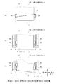
紙幣入出金機10において上段小収納カセット19Cがスロット28に装填される場合、図16に示すように、作業者等により上段小収納カセット19Cの取手61(図12等)が把持されて持ち上げられ、スロット28における上側部分に対し左上方に位置される(以下これを第1状態と呼ぶ)。因みに図16及び以降の図では、スロット28の上側部分及び上段小収納カセット19Cを前方から見た様子を、一部を簡略化ないし省略することにより模式的に表している。
[6-1. Loading operation and effect]
When the upper small storage cassette 19C is loaded into the slot 28 in the banknote depositing and dispensing machine 10, as shown in FIG. 16, the handle 61 (FIG. 12 etc.) of the upper small storage cassette 19C is grasped and lifted by an operator or the like. , The upper portion of the slot 28 is positioned at the upper left (hereinafter referred to as the first state). Incidentally, in FIG. 16 and the subsequent drawings, the upper portion of the slot 28 and the upper small storage cassette 19C as viewed from the front are schematically shown by simplifying or omitting a part thereof.

上段小収納カセット19Cは、この第1状態において、右前下突起82及び右後下突起83を、おおよそ左隙間49の範囲内に位置させるよう、作業者等によりその高さ(すなわち上下方向の位置)が調整される。   In this first state, the upper small storage cassette 19C has its height (that is, the position in the vertical direction) set by the operator or the like so that the right front lower protrusion 82 and the right rear lower protrusion 83 are positioned approximately within the range of the left gap 49. ) Is adjusted.

ここでスロット28は、上述したように前後左右の各側面のうち右側面のみが比較的高く、すなわち左側面が比較的低くなっている。このため紙幣入出金機10では、この第1状態において上段小収納カセット19Cをスロット28の左上方に位置させ、当該上段小収納カセット19Cに開口部33Hを横切らせることにより、当該上段小収納カセット19Cを持ち上げる高さを比較的小さく抑えることができる。   Here, in the slot 28, as described above, only the right side of the front, rear, left and right side surfaces is relatively high, that is, the left side surface is relatively low. For this reason, in the banknote depositing / dispensing machine 10, in this first state, the upper small storage cassette 19C is positioned at the upper left of the slot 28, and the upper small storage cassette 19C crosses the opening 33H, thereby the upper small storage cassette 19C. The height for lifting 19C can be kept relatively small.

ところで上段小収納カセット19Cは、スロット28に対し適正に装填される場合、当該上段小収納カセット19Cの前後左右の各側面及び下面を当該スロット28の前後左右の各内側面及び下内側面とそれぞれほぼ平行とした状態で真下へ下降することにより、カセット側コネクタ67を上段スロット側コネクタ38(図5)と嵌合させるように設計されている。以下では、スロット28の各内側面に対し上段小収納カセット19Cの各側面がほぼ平行となる角度を適正角度と呼び、またスロット28に対し上段小収納カセット19Cが適正に装填される位置を適正位置と呼ぶ。   By the way, when the upper small storage cassette 19C is properly loaded into the slot 28, the front and rear left and right side surfaces and the lower surface of the upper small storage cassette 19C are respectively connected to the front and rear left and right inner side surfaces and the lower inner side surface of the slot 28. The cassette-side connector 67 is designed to be fitted to the upper slot-side connector 38 (FIG. 5) by descending directly below in a substantially parallel state. Hereinafter, an angle at which each side surface of the upper small storage cassette 19C is substantially parallel to each inner side surface of the slot 28 is referred to as an appropriate angle, and a position where the upper small storage cassette 19C is properly loaded into the slot 28 is appropriate. Called position.

しかしながら、実際に第1状態にある上段小収納カセット19Cは、適正角度に対しx軸周り、y軸周り及びz軸周りにそれぞれ傾きを有している(回転している)可能性や、適正位置に対し前後方向(x方向)、上下方向(y方向)及び左右方向(z方向)にそれぞれずれを有している(移動している)可能性が高い。このため上段小収納カセット19Cは、仮にこの状態で下降されたとしても、カセット側コネクタ67を上段スロット側コネクタ38(図5)に対し正しく嵌合させることができず、接触不良や破損を引き起こす可能性がある。   However, the upper stage small storage cassette 19C that is actually in the first state may be inclined (rotated) around the x axis, the y axis, and the z axis with respect to the appropriate angle, There is a high possibility that the position is displaced (moved) in the front-rear direction (x direction), the up-down direction (y direction), and the left-right direction (z direction). For this reason, even if the upper-stage small storage cassette 19C is lowered in this state, the cassette-side connector 67 cannot be properly fitted to the upper-stage slot-side connector 38 (FIG. 5), causing contact failure or damage. there is a possibility.

この第1状態にある上段小収納カセット19Cは、まず作業者等により右方向へ押し付けようとする力が加えられ、右方向へ移動される。ここでスロット28における前後それぞれの右ガイド体39には、基板41の右上側に傾斜面41Aが形成されている。このため右ガイド体39は、この傾斜面41Aにより、上段小収納カセット19Cの右前下突起82及び右後下突起83における前後方向(すなわちx方向)の位置を、右方向への移動に伴って適正位置に近づけていくことができる。   The upper small storage cassette 19 </ b> C in the first state is first moved to the right by a force applied to the right by an operator or the like. Here, an inclined surface 41 </ b> A is formed on the upper right side of the substrate 41 in the front and rear right guide bodies 39 in the slot 28. For this reason, the right guide body 39 moves the position in the front-rear direction (that is, the x direction) of the right front lower protrusion 82 and the right rear lower protrusion 83 of the upper small storage cassette 19C to the right by the inclined surface 41A. It can be brought closer to the proper position.

またこのとき上段小収納カセット19Cは、作業者等により、右前下突起82及び右後下突起83を左隙間49の範囲内に合わせるよう、その高さ(すなわち上下方向の位置)が調整されながら、右方向へ移動される。   At this time, the height (that is, the vertical position) of the upper small storage cassette 19C is adjusted by an operator or the like so that the right front lower protrusion 82 and the right rear lower protrusion 83 are adjusted within the range of the left gap 49. Moved to the right.

やがて上段小収納カセット19Cは、図17及び図18に示すように、右前下突起82及び右後下突起83を前後それぞれの右ガイド体39における右側壁部43の少なくとも一方に当接させた段階で静止し、突出基部81が当該右側壁部43同士の間に入り込む(以下これを第2状態と呼ぶ)。   Eventually, as shown in FIGS. 17 and 18, the upper small storage cassette 19C has the right front lower protrusion 82 and the right rear lower protrusion 83 brought into contact with at least one of the right side wall portions 43 of the front and rear right guide bodies 39. The protruding base 81 enters between the right side walls 43 (hereinafter referred to as the second state).

因みに上段小収納カセット19Cは、仮に右前下突起82及び右後下突起83が左隙間49の範囲から外れて左下側壁部44又は左上側壁部47に当接した場合、作業者等によりそのまま上下方向へ摺動するように移動されることにより、やがて左隙間49の範囲内に入り、第2状態となる。   Incidentally, if the upper right lower projection 82 and the lower right rear projection 83 are out of the range of the left gap 49 and come into contact with the lower left side wall portion 44 or the upper left side wall portion 47, the upper small storage cassette 19C is moved in the vertical direction as it is. As a result of being moved so as to slide to the end, it eventually enters the range of the left gap 49 and enters the second state.

上段小収納カセット19Cは、この第2状態において、突出基部81が前後それぞれにおける右ガイド体39の右側壁部43により緩く挟まれているため、すなわち僅かに隙間を空けて挟まれているため、x方向(前後方向)に関し、その位置が概ね適正位置に合わせられると共に移動が規制される。   In the second state, the upper small storage cassette 19C is loosely sandwiched by the right side wall 43 of the right guide body 39 in the front and rear in each of the front and rear sides, that is, slightly sandwiched by a gap, With respect to the x direction (front-rear direction), the position is generally adjusted to an appropriate position and the movement is restricted.

また上段小収納カセット19Cは、右前下突起82及び右後下突起83が右ガイド体39の右側壁部43に当接しているため、右方向に関し、その位置がほぼ適正位置に合わせられると共に移動が規制され、且つ作業者による引き続き右方向へ押し付けようとする力により、左方向への移動も規制される。   Further, since the lower right front projection 82 and the lower right rear projection 83 are in contact with the right side wall 43 of the right guide body 39, the upper small storage cassette 19C is moved to the proper position with respect to the right direction. And the movement to the left is also restricted by the force of the operator who continues to press it to the right.

すなわち紙幣入出金機10では、この第2状態において、上段小収納カセット19Cを前後方向(x方向)に関して概ね適正位置に合わせることができると共に、左右方向(z方向)への移動を規制することができる。   That is, in the banknote depositing / dispensing machine 10, in the second state, the upper stage small storage cassette 19C can be adjusted to a generally appropriate position in the front-rear direction (x direction) and the movement in the left-right direction (z direction) is restricted. Can do.

ただし上段小収納カセット19Cは、この第2状態では、適正角度に対し少なくともy軸周りに回転している可能性があるため、右前下突起82及び右後下突起83のいずれか一方のみが右側壁部43に当接するものの他方が浮き上がっている(僅かに離れている)可能性がある。また上段小収納カセット19Cは、この第2状態において、左方向及び上下方向(y方向)へは自由に移動でき、且つx軸周り、y軸周りおよびz軸周りについてもそれぞれ自由に回転できる。   However, in this second state, the upper small storage cassette 19C may be rotated at least around the y-axis with respect to an appropriate angle, so only one of the right front lower protrusion 82 and the right rear lower protrusion 83 is on the right side. There is a possibility that the other side of the wall 43 is lifted (slightly separated). Further, in this second state, the upper small storage cassette 19C can freely move in the left direction and the vertical direction (y direction), and can freely rotate about the x axis, the y axis, and the z axis.

これを換言すれば、上段小収納カセット19Cは、第2状態において、これらの方向及び軸周りに関して装填姿勢の自由度を有しており、必ずしも適正位置若しくは適正角度となっている必要が無い。   In other words, in the second state, the upper small storage cassette 19C has a degree of freedom in the loading posture with respect to these directions and the axes, and does not necessarily have to be in an appropriate position or an appropriate angle.

ここでスロット28の前後に設けられた右ガイド体39同士の間隔は、上段小収納カセット19Cにおける筐体80の前後長、すなわち下段小収納カセット19Bにおける筐体70や大収納カセット19Aにおける筐体60の前後長よりも十分に狭くなっている。このため紙幣入出金機10では、図19に示すように、右ガイド体39同士の間隔が広い場合に生じ得る、大収納カセット19A及び下段小収納カセット19Bが正しい装填位置よりも右寄りに下降されて上段スロット側コネクタ38を破損することを、未然に防止できる。   Here, the interval between the right guide bodies 39 provided before and after the slot 28 is the front-rear length of the casing 80 in the upper small storage cassette 19C, that is, the casing 70 in the lower small storage cassette 19B and the casing in the large storage cassette 19A. It is sufficiently narrower than the longitudinal length of 60. For this reason, in the banknote depositing and dispensing machine 10, as shown in FIG. 19, the large storage cassette 19A and the lower small storage cassette 19B, which may occur when the interval between the right guide bodies 39 is wide, are lowered to the right from the correct loading position. Thus, it is possible to prevent the upper slot side connector 38 from being damaged.

次に上段小収納カセット19Cは、徐々に下方向へ移動され、図20及び図21に示すように、右前下突起82及び右後下突起83が前後それぞれにおける右ガイド体39の下溝部42内に陥入させていく(以下これを第3状態と呼ぶ)。   Next, the upper small storage cassette 19C is gradually moved downward, and as shown in FIGS. 20 and 21, the right front lower protrusion 82 and the right rear lower protrusion 83 are located in the lower groove portion 42 of the right guide body 39 in the front and rear, respectively. (This is hereinafter referred to as the third state).

このとき上段小収納カセット19Cは、突出基部81が右ガイド体39の右側壁部43により前後からわずかに隙間を空けて挟まれることに加え、右前下突起82及び右後下突起83が右ガイド体39の下溝部42にそれぞれ入り込み、右側壁部43及び左下側壁部44により左右方向からほぼ隙間なく挟まれる。   At this time, in the upper small storage cassette 19C, the protruding base 81 is sandwiched between the right side wall 43 of the right guide body 39 with a slight gap from the front and rear, and the right front lower protrusion 82 and the right rear lower protrusion 83 are The body 39 enters the lower groove portion 42 and is sandwiched between the right side wall portion 43 and the left lower side wall portion 44 from the left and right directions with almost no gap.

ここで、仮想的に、右ガイド体39(図8)において左下側壁部44が右側壁部43と同様に上端にまで設けられ、下溝部42が上端まで形成されていた場合を想定する。この場合、右前下突起82及び右後下突起83をこの下溝部42に陥入させるには、作業者等により、まず上段小収納カセット19Cの前後方向及び左右方向に関する位置をほぼ適正位置に合わせると共にy軸周りの回転についても適正角度に合わせることにより、右前下突起82及び右後下突起83を下溝部42の真上に位置させる必要がある。   Here, it is assumed that, in the right guide body 39 (FIG. 8), the lower left side wall portion 44 is provided to the upper end similarly to the right side wall portion 43, and the lower groove portion 42 is formed to the upper end. In this case, in order to insert the right front lower protrusion 82 and the right rear lower protrusion 83 into the lower groove portion 42, first, an operator or the like first adjusts the positions of the upper small storage cassette 19 </ b> C in the front-rear direction and the left-right direction to substantially proper positions. At the same time, it is necessary to position the right front lower protrusion 82 and the right rear lower protrusion 83 directly above the lower groove portion 42 by adjusting the rotation around the y axis to an appropriate angle.

さらにこの場合、上段小収納カセット19Cについては、前後方向及び左右方向の位置及びy軸周りの角度を保ったまま、真下に下降させる必要がある。すなわちこの場合、作業者等に対し、上段小収納カセット19Cの位置及び角度について極めて繊細な作業を求めることになり、作業性を大幅に低下させてしまう。   Furthermore, in this case, the upper stage small storage cassette 19C needs to be lowered directly while maintaining the position in the front-rear direction and the left-right direction and the angle around the y-axis. That is, in this case, an extremely delicate work is required for the operator and the like with respect to the position and angle of the upper small storage cassette 19C, and the workability is greatly reduced.

これに対し実際の右ガイド体39(図8)は、右側壁部43が上端まで形成されている一方、左下側壁部44が下側部分のみに形成されている。このため上段小収納カセット19Cは、第1状態(図16)において前後方向の位置のみが概ね適正位置にある状態で右方向へ移動され、右前下突起82及び右後下突起83のいずれか一方を右ガイド体39の右側壁部43に当接させることで、左右方向の位置を概ね適正位置に合わせることができる。   On the other hand, in the actual right guide body 39 (FIG. 8), the right side wall portion 43 is formed up to the upper end, while the lower left side wall portion 44 is formed only in the lower side portion. For this reason, the upper stage small storage cassette 19C is moved rightward with only the position in the front-rear direction being substantially in the first state (FIG. 16), and either the right front lower protrusion 82 or the right rear lower protrusion 83 is moved. Is brought into contact with the right side wall 43 of the right guide body 39, so that the position in the left-right direction can be adjusted to the appropriate position.

さらに上段小収納カセット19Cは、引き続き右方向へ押し付けられながらy軸周りに僅かに回転されることで、右前下突起82及び右後下突起83の双方が右ガイド体39の右側壁部43に当接した状態となり、左右方向の位置を適正位置に合わせると共にy軸周りの回転を適正角度に合わせることができる。   Further, the upper small storage cassette 19C is rotated slightly around the y axis while being pressed rightward, so that both the right front lower protrusion 82 and the right rear lower protrusion 83 are placed on the right wall 43 of the right guide body 39. It is in a contact state, and the position in the left-right direction can be adjusted to an appropriate position and the rotation around the y-axis can be adjusted to an appropriate angle.

このため作業者等は、上段小収納カセット19Cに対し右方向にやや力を加えながら下降させることにより、右前下突起82及び右後下突起83の少なくとも一方を右ガイド体39の右側壁部43に摺動させながら、当該右前下突起82及び右後下突起83を下溝部42内へ陥入させていくことができる。   For this reason, the operator or the like lowers the upper small storage cassette 19C while applying a slight rightward force, so that at least one of the right front lower protrusion 82 and the right rear lower protrusion 83 moves to the right side wall 43 of the right guide body 39. The right front lower protrusion 82 and the right rear lower protrusion 83 can be recessed into the lower groove portion 42 while being slid.

また、このときスロット28における前後の右ガイド体39は、左下側壁部44における上端左側にいわゆる面取り加工が施されているため、仮に右前下突起82及び右後下突起83が右側壁部43から浮き上がった状態であったとしても、その下降に伴って下溝部42内へ徐々に誘導していくことができる。   Further, at this time, the front and rear right guide bodies 39 in the slot 28 are so-called chamfered on the left side of the upper end of the left lower wall portion 44, so that the right front lower protrusion 82 and the right rear lower protrusion 83 are temporarily removed from the right wall portion 43. Even if it is in a lifted state, it can be gradually guided into the lower groove portion 42 as it is lowered.

ところで右ガイド体39は、下溝部42における上下方向の長さに対し、上溝部46における上下方向の長さの方が短くなっている。このため上段小収納カセット19Cは、この第3状態において、右前上突起84及び右後上突起85が右ガイド体39の上溝部46には入り込まず、宙に浮いた状態となる。   By the way, the right guide body 39 has a shorter vertical length in the upper groove portion 46 than a vertical length in the lower groove portion 42. Therefore, in this third state, the upper small storage cassette 19C is in a state where the right front upper protrusion 84 and the right rear upper protrusion 85 do not enter the upper groove portion 46 of the right guide body 39 and float in the air.

すなわち上段小収納カセット19Cは、下側の右前下突起82及び右後下突起83を下溝部42内へ陥入させていく際、作業者等に対し、上側の右前上突起84及び右後上突起85と上溝部46との位置関係に注意させる必要が無い。   That is, the upper small storage cassette 19 </ b> C has the upper right front upper protrusion 84 and the right rear upper protrusion to the operator or the like when the lower right front lower protrusion 82 and the right rear lower protrusion 83 are inserted into the lower groove portion 42. There is no need to pay attention to the positional relationship between the protrusion 85 and the upper groove portion 46.

さらに紙幣入出金機10では、この第3状態において、スロット28側の左ガイド体40に設けた溝部52に対し、上段小収納カセット19Cの左突起86が陥入されない。すなわち紙幣入出金機10は、この第3状態では、左側部分を適正位置に合わせる必要が無く、作業者等に対し、右側部分における下側部分のみに注意を向けさせ、右前下突起82及び右後下突起83を各下溝部42内へそれぞれ陥入させれば良い。   Furthermore, in the banknote depositing / dispensing machine 10, in the third state, the left protrusion 86 of the upper small storage cassette 19C is not inserted into the groove 52 provided in the left guide body 40 on the slot 28 side. That is, in this third state, the banknote depositing / dispensing machine 10 does not need to adjust the left side portion to an appropriate position, and causes the operator or the like to pay attention only to the lower side portion of the right side portion. The rear lower protrusion 83 may be recessed into each lower groove portion 42.

ここで右前下突起82及び右後下突起83は、その直径が下溝部42の溝幅よりもごく僅かに短くなっているため、当該下溝部42に陥入されることにより、上段小収納カセット19C全体として左右方向(z方向)に関する位置が適正位置に合わせられ、且つ左右方向への移動が規制される。   Here, since the diameters of the right front lower protrusion 82 and the right rear lower protrusion 83 are slightly shorter than the groove width of the lower groove portion 42, the upper small storage cassette is inserted into the lower groove portion 42. The position in the left-right direction (z direction) as a whole 19C is adjusted to an appropriate position, and movement in the left-right direction is restricted.

ところで上段小収納カセット19Cでは、図22(A)に模式図を示すように、右前下突起82の前面と右後下突起83の後面との前後方向の距離L1に対し、右前下突起82の前面における上端と右後下突起83の後面における下端とのように対角線方向の距離L2の方が長くなる。   By the way, in the upper stage small storage cassette 19C, as shown in a schematic diagram in FIG. 22A, the front right lower protrusion 82 is at a distance L1 between the front surface of the right front lower protrusion 82 and the rear surface of the right rear lower protrusion 83 in the front-rear direction. The diagonal distance L2 is longer like the upper end on the front surface and the lower end on the rear surface of the right rear lower protrusion 83.

このため、図22(B)に示すように、スロット28に取り付けられた前後の右ガイド体39における基板41同士の間隔である距離L3が、上段小収納カセット19Cにおける前後方向の距離L1よりも僅かに長い程度であった場合、この距離L3が対角方向の距離L2よりも短くなる可能性がある。   For this reason, as shown in FIG. 22B, the distance L3, which is the distance between the substrates 41 in the front and rear right guide bodies 39 attached to the slot 28, is larger than the distance L1 in the front-rear direction in the upper small storage cassette 19C. If the distance is slightly longer, the distance L3 may be shorter than the diagonal distance L2.

このような場合、上段小収納カセット19Cは、図22(C)に示すように、適正角度に対してz軸周りに回転した際に、右前下突起82及び右後下突起83が基板41にそれぞれ食い込むように当接した状態、いわゆるつかえた状態となってしまうため、上段小収納カセット19Cを下降させ得なくなる恐れがある。すなわちこの場合、作業員等が上段小収納カセット19Cを適正角度からz軸周りに極力回転させないように注意しながら下降させる必要があり、その作業性が極めて低下してしまう。   In such a case, as shown in FIG. 22C, the upper small storage cassette 19C has the right front lower protrusion 82 and the right rear lower protrusion 83 formed on the substrate 41 when rotated about the z axis with respect to an appropriate angle. Since each of them comes into contact with each other, that is, in a so-called gripped state, there is a possibility that the upper small storage cassette 19C cannot be lowered. That is, in this case, it is necessary for an operator or the like to lower the upper stage small storage cassette 19C with care so as not to rotate the z-axis as much as possible from an appropriate angle, and the workability is extremely lowered.

この点を踏まえ、実際の紙幣入出金機10では、基板41同士の間隔である距離L3に対し右前下突起82及び右後下突起83の前後方向の距離L1を十分に短くし、当該距離L3よりも対角線方向の距離L2の方が短くなるようにした。   In consideration of this point, in the actual banknote depositing and dispensing machine 10, the distance L1 in the front-rear direction of the right front lower protrusion 82 and the right rear lower protrusion 83 is sufficiently shortened with respect to the distance L3 that is the distance between the substrates 41, and the distance L3. The distance L2 in the diagonal direction is shorter than that.

これを換言すれば、紙幣入出金機10では、スロット28に対する上段小収納カセット19Cの前後方向(x方向)に関する位置を、右前下突起82及び右後下突起83と下溝部42との関係ではなく、突出基部81の前面及び後面と右ガイド体39の右側壁部43との関係により規制するようにした。   In other words, in the banknote depositing / dispensing machine 10, the position of the upper small storage cassette 19 </ b> C with respect to the slot 28 in the front-rear direction (x direction) is the relationship between the lower right front protrusion 82, the lower right rear protrusion 83, and the lower groove portion 42. Instead, it is regulated by the relationship between the front and rear surfaces of the protruding base 81 and the right side wall 43 of the right guide body 39.

このため紙幣入出金機10では、上段小収納カセット19Cを適正角度からz軸周りに回転した際にも右前下突起82の前面及び右後下突起83の後面が基板41から離れた状態を維持でき、z軸周りに多少回転したとしても、つかえること無く下降させることができる。   For this reason, in the banknote depositing and dispensing machine 10, the front surface of the right front lower protrusion 82 and the rear surface of the right rear lower protrusion 83 are kept away from the substrate 41 even when the upper small storage cassette 19 </ b> C is rotated around the z axis from an appropriate angle. Even if it is slightly rotated around the z axis, it can be lowered without being caught.

すなわち上段小収納カセット19Cは、この第3状態において、前後方向(x方向)の位置が概ね適正位置に合わせられて移動がほぼ規制されると共に、左右方向(z方向)の位置が適正位置に合わせられて移動が規制され、これに伴ってy軸周りの回転も規制される。   That is, in this third state, the upper small storage cassette 19C is substantially restricted in movement in the front-rear direction (x direction) and is substantially regulated, and the left and right direction (z direction) position is in the proper position. Together, the movement is restricted, and accordingly, the rotation around the y-axis is also restricted.

その一方で上段小収納カセット19Cは、右前下突起82及び右後下突起83が右ガイド体39の下溝部42内を上下方向にそれぞれ移動できるため、上下方向(y方向)に関し自由に移動することができ、またz軸周りにも自由に回転することができる。さらに上段小収納カセット19Cは、右前下突起82及び右後下突起83を何れも円柱状に形成し、且つ互いの中心軸を揃えているため、これらを中心軸としてx軸周りに自由に回転することもできる。   On the other hand, the upper small storage cassette 19C moves freely in the vertical direction (y direction) because the right front lower protrusion 82 and the right rear lower protrusion 83 can move in the vertical direction in the lower groove portion 42 of the right guide body 39, respectively. It can also rotate freely about the z axis. Further, since the upper small storage cassette 19C has both the right front lower projection 82 and the right rear lower projection 83 formed in a cylindrical shape and the center axes thereof are aligned with each other, they can freely rotate around the x-axis with these as the central axes. You can also

すなわち上段小収納カセット19Cは、上下方向(y方向)の位置並びにz軸周り及びx軸周りの角度に関して、適正位置及び適正角度から外れた状態にある可能性がある。換言すれば、上段小収納カセット19Cは、この第3状態において、上下方向(y方向)の位置並びにz軸周り及びx軸周りの角度に関して、未だに装填姿勢の自由度を有しており、必ずしも適正位置若しくは適正角度となっている必要が無い。   That is, the upper small storage cassette 19C may be out of the proper position and proper angle with respect to the position in the vertical direction (y direction) and the angles around the z axis and the x axis. In other words, in this third state, the upper stage small storage cassette 19C still has a degree of freedom of the loading posture with respect to the position in the vertical direction (y direction) and the angles around the z axis and the x axis. There is no need for the proper position or angle.

続いて上段小収納カセット19Cは、図23及び図24に示すように、さらに下方向へ移動され、左突起86が左ガイド体40の溝部52内に入っていくと共に、右前上突起84及び右後上突起85が右ガイド体39の上溝部46内に入っていく(以下これを第4状態と呼ぶ)。   Subsequently, as shown in FIGS. 23 and 24, the upper small storage cassette 19C is further moved downward, and the left protrusion 86 enters the groove 52 of the left guide body 40, and the right front upper protrusion 84 and the right The rear upper protrusion 85 enters the upper groove portion 46 of the right guide body 39 (hereinafter referred to as the fourth state).

ここで、左突起86は上下方向に細長く形成されると共に下端近傍に丸め処理が施されている。また左ガイド体40は、一部の稜部に面取り処理が施されている。このため上段小収納カセット19Cは、左突起86が溝部52の真上からやや外れた位置にあったとしても、また適正角度に対しz軸周りに多少回転していたとしても、その下降に伴って左突起86を溝部52内へ徐々に誘導していくことができる。   Here, the left protrusion 86 is formed elongated in the vertical direction and rounded in the vicinity of the lower end. Further, the left guide body 40 is chamfered at a part of the ridges. Therefore, even if the upper small storage cassette 19C is located at a position where the left protrusion 86 is slightly off from directly above the groove 52, or even slightly rotated around the z-axis with respect to the appropriate angle, the upper small storage cassette 19C Thus, the left protrusion 86 can be gradually guided into the groove 52.

また左突起86は、上下方向に細長く形成されているため、左ガイド体40の溝部52内において、前側壁部53及び後側壁部54に対し、上下方向に離れた2箇所以上において当接若しくは極めて近接する。すなわち左ガイド体40は、上段小収納カセット19Cの左突起86が溝部52内に入り込むことにより、z軸周りに関し、当該上段小収納カセット19Cの回転を規制してほぼ適正角度に合わせることができる。   Further, since the left protrusion 86 is formed to be elongated in the vertical direction, in the groove portion 52 of the left guide body 40, the left projection 86 abuts on the front side wall portion 53 and the rear side wall portion 54 at two or more locations separated in the vertical direction. Very close. That is, the left guide body 40 can adjust the rotation of the upper small storage cassette 19 </ b> C to an approximately appropriate angle around the z axis by the left protrusion 86 of the upper small storage cassette 19 </ b> C entering the groove 52. .

さらに上段小収納カセット19Cは、この第4状態において、筐体80の左側面を左ガイド体40の右側面に極めて近接させ、若しくは一部当接させる。これにより上段小収納カセット19Cは、x軸周りの回転が大きく規制され、自由に回転できる範囲が極めて狭くなる。またこのとき上段小収納カセット19Cは、筐体80の前面及び後面の下端近傍を、仕切板36(図6、図7)の上端近傍に近接若しくは当接させる。   Further, in the fourth state, the upper small storage cassette 19 </ b> C makes the left side surface of the housing 80 extremely close to the right side surface of the left guide body 40, or makes a partial contact. As a result, the upper small storage cassette 19C is largely restricted from rotating around the x axis, and the range in which it can freely rotate becomes extremely narrow. Further, at this time, the upper small storage cassette 19C brings the vicinity of the lower end of the front surface and the rear surface of the housing 80 close to or in contact with the vicinity of the upper end of the partition plate 36 (FIGS. 6 and 7).

これに加えて上段小収納カセット19Cは、右前上突起84及び右後上突起85が上溝部46内に入っていくことによっても、x軸周りの回転が大きく規制される。   In addition, the rotation of the upper stage small storage cassette 19 </ b> C around the x axis is largely restricted by the right front upper projection 84 and the right rear upper projection 85 entering the upper groove portion 46.

すなわち紙幣入出金機10では、上段小収納カセット19Cが第3状態から第4状態になることにより、z軸周りの回転角度が新たに適正角度に合わせられた状態に規制され、またx軸周りの回転角度が適正角度に近い状態に規制される。   That is, in the banknote depositing / dispensing machine 10, when the upper stage small storage cassette 19C is changed from the third state to the fourth state, the rotation angle around the z axis is newly regulated to an appropriate angle, and around the x axis. The rotation angle is regulated to a state close to an appropriate angle.

これを換言すれば上段小収納カセット19Cは、この第4状態において、前後方向(x方向)及び左右方向(z方向)に関してほぼ適正位置に合わせられ、且つy軸周り及びz軸周りの回転が何れも規制されてほぼ適正角度となる。その一方で上段小収納カセット19Cは、第3状態から引き続き上下方向(y方向)については自由に移動することができ、またx軸周りにも僅かながら回転することができる。   In other words, in the fourth state, the upper small storage cassette 19C is substantially aligned with the front-rear direction (x direction) and the left-right direction (z direction), and rotates about the y axis and the z axis. In any case, the angle is regulated to be an appropriate angle. On the other hand, the upper stage small storage cassette 19C can move freely in the vertical direction (y direction) from the third state, and can also rotate slightly around the x axis.

このとき上段小収納カセット19Cのカセット側コネクタ93は、スロット28の上段スロット側コネクタ38(図5)に対し、ほぼ真上の位置にあり、且つy軸周り及びz軸周りに関し適正角度にあり、さらにx軸周りに関し適正角度に比較的近い状態にある。   At this time, the cassette side connector 93 of the upper stage small storage cassette 19C is substantially directly above the upper slot side connector 38 (FIG. 5) of the slot 28, and is at an appropriate angle with respect to the y axis and the z axis. Furthermore, it is in a state relatively close to an appropriate angle around the x axis.

最後に上段小収納カセット19Cは、作業者等によりさらに下方向へ移動されることにより、右前下突起82及び右後下突起83を右ガイド体39の下溝部42に沿って摺動させると共に右前上突起84及び右後上突起85を上溝部46に沿って摺動させ、さらに左突起86を左ガイド体40の溝部52に沿って摺動させる。このため上段小収納カセット19Cは、回転角度を殆ど変化させることなく、ほぼ真下へ進行する。   Finally, the upper stage small storage cassette 19C is further moved downward by an operator or the like, thereby sliding the right front lower projection 82 and the right rear lower projection 83 along the lower groove portion 42 of the right guide body 39 and the right front The upper protrusion 84 and the right rear upper protrusion 85 are slid along the upper groove portion 46, and the left protrusion 86 is slid along the groove portion 52 of the left guide body 40. For this reason, the upper stage small storage cassette 19 </ b> C advances almost directly without changing the rotation angle.

これにより上段小収納カセット19Cは、図25に示すように、右前下突起82及び右後下突起83を右ガイド体39の下ストッパ45にそれぞれ当接させると共に、右前上突起84及び右後上突起85を上ストッパ48にそれぞれ当接させ、さらに左突起86を左ガイド体40のストッパ55に当接させる(以下これを第5状態と呼ぶ)。   As a result, as shown in FIG. 25, the upper small storage cassette 19C causes the right front lower protrusion 82 and the right rear lower protrusion 83 to contact the lower stopper 45 of the right guide body 39, and the right front upper protrusion 84 and the right rear upper protrusion. The protrusion 85 is brought into contact with the upper stopper 48, and the left protrusion 86 is brought into contact with the stopper 55 of the left guide body 40 (hereinafter referred to as the fifth state).

ここで上段小収納カセット19Cは、第4状態において、カセット側コネクタ93を上段スロット側コネクタ38のほぼ真上に位置させ、且つy軸周り及びz軸周りに関し適正角度にあり、さらにx軸周りに関し適正角度に比較的近くなっている。   Here, in the fourth state, the upper-stage small storage cassette 19C has the cassette-side connector 93 positioned almost directly above the upper-stage slot-side connector 38, and is at an appropriate angle with respect to the y-axis and the z-axis. Is relatively close to the proper angle.

このため上段小収納カセット19Cは、右ガイド体39及び左ガイド体40により案内されながら真下へ下降するだけで、当該カセット側コネクタ93が上段スロット側コネクタ38と摺動することによりx軸周りに適正角度に近づくよう回転しながら、正しい角度で嵌合させることができる。   For this reason, the upper small storage cassette 19 </ b> C simply descends while being guided by the right guide body 39 and the left guide body 40, and the cassette side connector 93 slides with the upper slot side connector 38 to move around the x axis. While rotating to approach the appropriate angle, it can be fitted at the correct angle.

すなわち紙幣入出金機10は、図26(A)〜(D)に示すように、上段小収納カセット19Cが適正角度に対し各軸周りに回転していた場合に生じ得る、カセット側コネクタ93と上段スロット側コネクタ38がずれた状態で無理に嵌合されて破損することを未然に防止できる。   That is, as shown in FIGS. 26 (A) to (D), the banknote depositing and dispensing machine 10 includes a cassette-side connector 93 that can be generated when the upper small storage cassette 19C is rotated around each axis with respect to an appropriate angle. It is possible to prevent the upper slot side connector 38 from being forcibly fitted and damaged in a shifted state.

このように紙幣入出金機10では、第1状態(図16)から上段小収納カセット19Cが右方向へ移動された後、徐々に下降されることにより、まず右前下突起82及び右後下突起83を右ガイド体39の下溝部42にそれぞれ陥入させ、次に左突起86を左ガイド体40の溝部52へ陥入させ、さらに右前上突起84及び右後上突起85を右ガイド体39の上溝部46にそれぞれ陥入させる。   Thus, in the banknote depositing / dispensing machine 10, after the upper stage small storage cassette 19C is moved rightward from the first state (FIG. 16), it is gradually lowered, so that the right front lower projection 82 and the right rear lower projection first. 83 is inserted into the lower groove portion 42 of the right guide body 39, the left projection 86 is then inserted into the groove portion 52 of the left guide body 40, and the right front upper projection 84 and the right rear upper projection 85 are inserted into the right guide body 39. The upper grooves 46 are respectively invaginated.

このとき紙幣入出金機10では、上段小収納カセット19Cの回転に関する装填姿勢の自由度に着目すると、当該上段小収納カセット19Cがスロット28内で下降されるに連れて、まずy軸周りの回転を規制した後、次にz軸周りの回転を規制し、最後にx軸周りの回転を規制することになる。   At this time, in the banknote depositing / dispensing machine 10, paying attention to the degree of freedom of the loading posture related to the rotation of the upper small storage cassette 19C, as the upper small storage cassette 19C is lowered in the slot 28, first the rotation around the y-axis. Then, the rotation around the z-axis is restricted, and finally the rotation around the x-axis is restricted.

またこのとき紙幣入出金機10では、上段小収納カセット19Cの移動に関する装填姿勢の自由度に着目すると、当該上段小収納カセット19Cがスロット28内で下降されるに連れて、まず前後方向(x方向)への移動を規制し、次に左右方向(z方向)への移動を規制し、最後に上下方向(y方向)への移動を規制することになる。   At this time, in the banknote depositing / dispensing machine 10, paying attention to the degree of freedom of the loading posture with respect to the movement of the upper small storage cassette 19C, as the upper small storage cassette 19C is lowered in the slot 28, first the front-rear direction (x Movement in the direction), then movement in the left-right direction (z direction) is restricted, and finally movement in the up-down direction (y direction) is restricted.

すなわち紙幣入出金機10は、上段小収納カセット19Cの右方向への移動及び下方向への移動に伴い、移動及び回転に関する装填姿勢の自由度を徐々に制限していくことができるので、複数の自由度を突然制限する場合に必要となる緻密な位置調整のような困難な作業の発生を回避し、作業性を低下させること無く円滑に装填させることができる。   That is, the banknote depositing / dispensing machine 10 can gradually limit the degree of freedom of the loading posture with respect to movement and rotation as the upper stage small storage cassette 19C moves rightward and downwards. Thus, it is possible to avoid the occurrence of difficult work such as precise position adjustment required when suddenly limiting the degree of freedom, and smoothly load the work without degrading workability.

また、スロット28(図6)は、前後左右の各側面のうち、右ガイド体39を設けた右側部32のみを比較的高くしておけば良く、左ガイド体40を設けた左側部33や仕切板36等のような他の各側面を比較的低く抑えることができる。   Further, the slot 28 (FIG. 6) requires only the right side 32 provided with the right guide body 39 among the front, rear, left and right side surfaces to be relatively high. Other side surfaces such as the partition plate 36 can be kept relatively low.

これにより紙幣入出金機10では、スロット28内部に対する斜め上方からの視認性を大幅に高めることができると共に、大収納カセット19A及び下段小収納カセット19Bを装填する際又は取り出す際にその下端を持ち上げるべき高さを、右側部32の上端以上では無く、左側部33及び仕切板36等の上端以上とすれば良いため、作業性を高めることができる。   Thereby, in the banknote depositing / dispensing machine 10, the visibility from the oblique upper side with respect to the inside of the slot 28 can be greatly improved, and the lower end is lifted when the large storage cassette 19A and the lower small storage cassette 19B are loaded or taken out. Since the power height should not be higher than the upper end of the right side portion 32 but higher than the upper end of the left side portion 33 and the partition plate 36, workability can be improved.

また上段小収納カセット19Cは、右前下突起82及び右後下突起83を突出基部81の上下方向に関し中央よりも下方、特に下端寄りの位置であって、カセット側コネクタ93の近傍であり、且つ当該カセット側コネクタ93を前後から、すなわち長手方向の両側から挟むような位置に配置した。   Further, the upper stage small storage cassette 19C has the right front lower projection 82 and the right rear lower projection 83 at a position below the center, particularly near the lower end in the vertical direction of the protruding base 81, in the vicinity of the cassette side connector 93, and The cassette-side connector 93 is disposed at a position sandwiched from the front and rear, that is, from both sides in the longitudinal direction.

これにより紙幣入出金機10は、スロット28に当該上段小収納カセット19Cが装填された際に、当該カセット側コネクタ93の近傍で上段スロット側コネクタ38に対し精度良く位置を合わせながら近づけることができ、各コネクタの破損を未然に防止できる。   Thereby, when the upper stage small storage cassette 19C is loaded in the slot 28, the banknote depositing / dispensing machine 10 can be brought close to the upper stage slot side connector 38 in the vicinity of the cassette side connector 93 while accurately aligning the position. It is possible to prevent damage to each connector.

さらに紙幣入出金機10は、スロット28に対する上段小収納カセット19Cの装填位置を定める右前下突起82及び右後下突起83並びに左突起86を、筐体80の下寄りにおける左右両側であって、下受渡口89を左右から挟むような位置にそれぞれ配置した。これにより上段小収納カセット19Cは、当該下受渡口89の左右両端の近傍でそれぞれ位置合わせできるので、下段小収納カセット19Bの受渡口62(図11、図15)に対する前後方向の位置精度を高めることができる。   Furthermore, the banknote depositing / dispensing machine 10 includes a right front lower projection 82, a right rear lower projection 83, and a left projection 86 that define a loading position of the upper small storage cassette 19C with respect to the slot 28 on the left and right sides of the lower side of the housing 80, The lower delivery port 89 was arranged at a position sandwiching from the left and right. As a result, the upper small storage cassette 19C can be positioned in the vicinity of the left and right ends of the lower delivery port 89, so that the positional accuracy of the lower small storage cassette 19B with respect to the delivery port 62 (FIGS. 11 and 15) is improved. be able to.

特に紙幣入出金機10では、内部の各搬送路において紙幣の紙面を前後からローラ等により挟んで短辺方向に沿って搬送しており、且つ下受渡口89及び受渡口62等の各受渡口において紙幣の紙面を前後に向けているため、左右方向に関する位置ずれについては比較的余裕があるものの、前後方向についての位置ずれを極力抑える必要がある。   In particular, in the banknote depositing / dispensing machine 10, the paper surface of the banknote is transported along the short side direction between the front and rear by rollers or the like in each internal transport path, and each delivery port such as the lower delivery port 89 and the delivery port 62 is provided. In FIG. 2, since the paper surface of the banknote is directed forward and backward, there is a relatively large margin for positional deviation in the horizontal direction, but it is necessary to suppress positional deviation in the longitudinal direction as much as possible.

この点において上段小収納カセット19Cは、長手方向である左右両端においてスロット28に対し位置決めをすることができるので、左突起86を省略して右側のみにおいて位置決めする場合と比較しても、下段小収納カセット19Bの受渡口62に対する下受渡口89の位置を適切に合わせることができ、紙幣の受け渡しの精度を高めることができる。   In this respect, the upper small storage cassette 19C can be positioned with respect to the slot 28 at both the left and right ends in the longitudinal direction. Therefore, the lower small storage cassette 19C is smaller than the case where the left protrusion 86 is omitted and only the right side is positioned. The position of the lower delivery port 89 with respect to the delivery port 62 of the storage cassette 19B can be appropriately adjusted, and the accuracy of bill delivery can be improved.

また紙幣入出金機10では、上段小収納カセット19Cを、下段小収納カセット19Bでは無く、スロット28に対し位置決めするようにした。一方、下段小収納カセット19Bは、上述したように、スロット28に装填された状態において、その上端にある受渡口62の位置を厳密には位置決めしておらず、前後左右の位置に関し自由度を有している。   Moreover, in the banknote depositing / dispensing machine 10, the upper stage small storage cassette 19C is positioned with respect to the slot 28, not the lower stage small storage cassette 19B. On the other hand, as described above, the lower-stage small storage cassette 19B does not strictly position the delivery port 62 at the upper end in the state of being loaded in the slot 28, and has a degree of freedom regarding the front-rear and left-right positions. Have.

このため紙幣入出金機10は、上段小収納カセット19Cを適正位置に装填する際に、下受渡口89の近傍に設けた突起89Pを下段小収納カセット19Bにおける受渡口62の近傍に設けた孔部62Qと嵌合させることで、下受渡口89に対し受渡口62を正しく対向させるように、下段小収納カセット19Bにおける上端の位置を微調整できる。   For this reason, when the banknote depositing / dispensing machine 10 loads the upper small storage cassette 19C into an appropriate position, a hole 89P provided in the vicinity of the lower delivery port 89 is provided in the vicinity of the delivery port 62 in the lower delivery cassette 19B. By fitting with the portion 62Q, the position of the upper end in the lower small storage cassette 19B can be finely adjusted so that the delivery port 62 is correctly opposed to the lower delivery port 89.

他の観点から見れば、紙幣入出金機10は、仮にスロット28に対する下段小収納カセット19Bの装填状態が悪く、受渡口62が正しい位置に対し多少の位置ずれを有していたとしても、上段小収納カセット19Cを当該スロット28に対し適正位置に装填させることができるので、上下方向への積み重ねによる位置ずれの累積を発生させることが無い。これにより紙幣入出金機10は、上受渡口88(図12、図15)の位置を、蓋体部26(図4)の受渡口26Aに精度良く合わせることができる。   From another point of view, the banknote depositing / dispensing machine 10 has an upper stage even if the loading state of the lower small storage cassette 19B with respect to the slot 28 is poor and the delivery port 62 has a slight positional deviation from the correct position. Since the small storage cassette 19C can be loaded at an appropriate position with respect to the slot 28, accumulation of misalignment due to vertical stacking does not occur. Thereby, the banknote depositing / withdrawing machine 10 can adjust the position of the upper delivery port 88 (FIGS. 12 and 15) to the delivery port 26A of the lid portion 26 (FIG. 4) with high accuracy.

さらに上段小収納カセット19Cは、比較的下端寄りに設けた右前下突起82及び右後下突起83並びに左突起86によりスロット28に対する位置を定めているため、その上端近傍において位置の自由度が比較的大きくなり、装填後もある程度の自由度を確保できる。   Further, since the upper small storage cassette 19C is positioned relative to the slot 28 by the right front lower projection 82, the right rear lower projection 83 and the left projection 86 provided relatively close to the lower end, the degree of freedom of position is compared in the vicinity of the upper end. A certain degree of freedom can be secured even after loading.

このため紙幣入出金機10では、蓋体部26(図4)を閉塞した際に、突起26APと上段小収納カセット19Cの孔部88Qとを嵌合させることにより、当該上段小収納カセット19Cにおける上受渡口88の位置を、蓋体部26の受渡口26Aに合わせて微調整することができ、両者の間で紙幣を精度良く受け渡すことが可能となる。   For this reason, in the banknote depositing / dispensing machine 10, when the lid portion 26 (FIG. 4) is closed, the protrusion 26AP and the hole 88Q of the upper small storage cassette 19C are fitted to each other, thereby The position of the upper delivery port 88 can be finely adjusted according to the delivery port 26A of the lid part 26, and it becomes possible to deliver a banknote accurately between both.

また上段小収納カセット19Cは、第4状態(図23)において右前下突起82及び右後下突起83が右ガイド体39の下溝部42内に入り、且つ左突起86が左ガイド体40の溝部52に入った後に、右前上突起84及び右後上突起85が右ガイド体39の上溝部46に入るようにした。このため上段小収納カセット19Cは、右前下突起82、右後下突起83及び左突起86によりスロット28に対し位置決めがなされる際に右前上突起84及び右後上突起85の位置を気にさせる必要が無く、また右前上突起84及び右後上突起85により位置や角度が制限されて作業性が低下することもない。   Further, in the upper stage small storage cassette 19C, in the fourth state (FIG. 23), the right front lower protrusion 82 and the right rear lower protrusion 83 enter the lower groove portion 42 of the right guide body 39, and the left protrusion 86 is the groove portion of the left guide body 40. After entering 52, the right front upper protrusion 84 and the right rear upper protrusion 85 enter the upper groove portion 46 of the right guide body 39. For this reason, the upper small storage cassette 19C cares about the positions of the right front upper protrusion 84 and the right rear upper protrusion 85 when the right front lower protrusion 82, the right rear lower protrusion 83, and the left protrusion 86 are positioned with respect to the slot 28. There is no need, and the position and angle are limited by the right front upper protrusion 84 and the right rear upper protrusion 85, and workability is not deteriorated.

さらに紙幣入出金機10は、スロット28の右ガイド体39及び左ガイド体40において、下溝部42及び溝部52の下端に下ストッパ45及びストッパ55を形成した。これにより紙幣入出金機10は、上段小収納カセット19Cがスロット28に装填され、重力の作用も加わって右前下突起82及び右後下突起83を下ストッパ45に当接させると共に右前上突起84及び右後上突起85を上ストッパ48に当接させ、さらに左突起86をストッパ55に当接させた段階で、当該上段小収納カセット19Cの下方向への移動を規制し、その位置を固定することができる。   Further, the banknote depositing and dispensing machine 10 has a lower stopper 45 and a stopper 55 formed at the lower ends of the lower groove portion 42 and the groove portion 52 in the right guide body 39 and the left guide body 40 of the slot 28. As a result, in the banknote depositing and dispensing machine 10, the upper small storage cassette 19 </ b> C is loaded in the slot 28, and the right front lower protrusion 82 and the right rear lower protrusion 83 are brought into contact with the lower stopper 45 and the right front upper protrusion 84 is added with the action of gravity. And when the right rear upper projection 85 is brought into contact with the upper stopper 48 and the left projection 86 is brought into contact with the stopper 55, the downward movement of the upper small storage cassette 19C is restricted and the position thereof is fixed. can do.

このため紙幣入出金機10は、例えば図27(A)に示すようにスロット28に下段小収納カセット19Bが装填されている場合のみに限らず、図27(B)に示すように当該下段小収納カセット19Bが装填されていない場合であっても、上段小収納カセット19Cを適正位置に且つ適正角度で保持することができる。   For this reason, the banknote depositing / dispensing machine 10 is not limited to the case where the lower small storage cassette 19B is loaded in the slot 28 as shown in FIG. 27A, for example, but as shown in FIG. Even when the storage cassette 19B is not loaded, the upper small storage cassette 19C can be held at an appropriate position and at an appropriate angle.

この結果、紙幣入出金機10は、スロット28から下段小収納カセット19Bを取り外した状態においても、カセット側コネクタ93や上段スロット側コネクタ38等に過大な力が加わることによる破損を発生させること無く、上段小収納カセット19Cを正しく稼働させることができる。これにより現金自動預払機1は、正常に運用でき顧客との間で入金取引や出金取引を行い得る可能性、いわゆる可用性を高めることができる。   As a result, the banknote depositing / dispensing machine 10 does not cause damage due to excessive force applied to the cassette-side connector 93, the upper slot-side connector 38, and the like even when the lower small storage cassette 19B is removed from the slot 28. The upper stage small storage cassette 19C can be operated correctly. Thereby, the automatic teller machine 1 can be normally operated and can increase the possibility of performing a deposit transaction and a withdrawal transaction with a customer, that is, so-called availability.

またスロット28は、大収納カセット19A及び下段小収納カセット19Bが装填時に通過する軌跡の範囲外に、右ガイド体39、左ガイド体40及び上段スロット側コネクタ38を設けた(図5、図6、図7)。これに応じて上段小収納カセット19Cは、突出基部81、右前下突起82、右後下突起83、右前上突起84、右後上突起85、左突起86及びカセット側コネクタ93を、筐体80の外方に設けた(図12、図13)。   The slot 28 is provided with a right guide body 39, a left guide body 40, and an upper slot side connector 38 outside the range of the trajectory through which the large storage cassette 19A and the lower small storage cassette 19B pass (FIGS. 5 and 6). , FIG. 7). Accordingly, the upper small storage cassette 19C includes a protruding base 81, a right front lower protrusion 82, a right rear lower protrusion 83, a right front upper protrusion 84, a right rear upper protrusion 85, a left protrusion 86, and a cassette side connector 93. (Figs. 12 and 13).

このため紙幣入出金機10では、スロット28に大収納カセット19A又は下段小収納カセット19Bを装填する際に、右ガイド体39及び左ガイド体40、或いは上段スロット側コネクタ38の各部品と干渉せずに装填させることができ、これらの部品の格納や引き出しのような作業を行わせる必要が無く、また保守作業員のケアレスミス等による各部品の破損が発生することも無い。   Therefore, in the banknote depositing / dispensing machine 10, when the large storage cassette 19A or the lower small storage cassette 19B is loaded into the slot 28, it interferes with each component of the right guide body 39 and the left guide body 40 or the upper slot side connector 38. Therefore, it is not necessary to perform operations such as storing and pulling out these parts, and there is no possibility that the parts are damaged due to a careless mistake of a maintenance worker.

さらに紙幣入出金機10では、スロット28の周側部分を形成する左側部33及び仕切板36の高さを、上段スロット側コネクタ38の上端よりも高くした(図5)。これにより紙幣入出金機10では、例えば図28(A)及び(B)に示すように、上段小収納カセット19C等が適正角度に対してy軸周りに大きく回転している状態で下降されたとしても、筐体80の底板部80B等を左側部33及び仕切板36の上端に当接させることができる。すなわち紙幣入出金機10では、保守作業員のケアレスミス等による上段スロット側コネクタ38に対する底板部80B等の衝突及びこれに伴う破損を未然に防止できる。   Further, in the banknote depositing / dispensing machine 10, the height of the left side portion 33 and the partition plate 36 forming the peripheral side portion of the slot 28 is set higher than the upper end of the upper slot side connector 38 (FIG. 5). Thereby, in the banknote depositing / dispensing machine 10, for example, as shown in FIGS. 28 (A) and 28 (B), the upper small storage cassette 19C and the like are lowered in a state of being largely rotated around the y axis with respect to an appropriate angle. Even so, the bottom plate portion 80B and the like of the housing 80 can be brought into contact with the left side portion 33 and the upper end of the partition plate 36. That is, in the banknote depositing / dispensing machine 10, it is possible to prevent the bottom plate portion 80 </ b> B and the like from colliding with the upper slot side connector 38 due to a careless mistake of a maintenance worker and the damage accompanying the collision.

さらに上段小収納カセット19Cは、取手61(図11)が回動部61Cにおいて筐体80に対しz軸周りに回動するようにした。このため上段小収納カセット19Cは、作業者により取手61が把持されている場合、左右方向(z方向)へは容易に位置調整させ得るものの、前後方向(x方向)には取手61に対し筐体80が意に反して回動してしまう場合があるため、その位置調整が必ずしも容易ではなく、他方の手により当該筐体80を支持させる必要が生じる可能性がある。   Further, the upper small storage cassette 19 </ b> C is configured such that the handle 61 (FIG. 11) rotates around the z axis with respect to the housing 80 in the rotating portion 61 </ b> C. For this reason, when the handle 61 is gripped by an operator, the upper small storage cassette 19C can be easily adjusted in position in the left-right direction (z direction), but in the front-back direction (x direction) with respect to the handle 61. Since the body 80 may turn unexpectedly, the position adjustment is not always easy, and the case 80 may need to be supported by the other hand.

この点を踏まえて紙幣入出金機10では、スロット28に上段小収納カセット19Cを装填させる際に、最初に当該上段小収納カセット19Cを右方向へ移動させるようにしたため(図16、図17)、片手で取手61が把持されている状態であっても、筐体80を他方の手で支持させること無く、容易にその位置を合わせさせることができる。   In consideration of this point, in the bill depositing / dispensing machine 10, when the upper small storage cassette 19C is loaded in the slot 28, the upper small storage cassette 19C is first moved rightward (FIGS. 16 and 17). Even in the state where the handle 61 is held with one hand, the position can be easily adjusted without supporting the housing 80 with the other hand.

さらに右ガイド体39の上ストッパ48は、左側に対して右側が低い傾斜面を形成するようにした。このため上ストッパ48は、例えばスロット28から上段小収納カセット19Cが取り出される際に上方向へ持ち上げられ、右前下突起82及び右後下突起83が上ストッパ48に当接したとしても、その傾斜方向に沿って上段小収納カセット19C全体を右方向へ案内し、スムーズに取り出させることができる。   Further, the upper stopper 48 of the right guide body 39 forms an inclined surface whose right side is lower than the left side. Therefore, the upper stopper 48 is lifted upward when the upper small storage cassette 19C is taken out of the slot 28, for example, and even if the right front lower protrusion 82 and the right rear lower protrusion 83 abut against the upper stopper 48, the upper stopper 48 is inclined. The entire upper stage small storage cassette 19C can be guided to the right along the direction and can be taken out smoothly.

また上段小収納カセット19Cは、スロット28に装填される際、仮に第1状態(図16)において右前下突起82及び右後下突起83の位置が左隙間49よりも高い位置にある場合、右方向へ移動されると、当該右前下突起82及び右後下突起83を左上側壁部47に衝突させることになる。しかしながらこの場合、上段小収納カセット19Cは、右前下突起82及び右後下突起83を左上側壁部47に摺動させるようにして下方へ移動させることにより、やがて上ストッパ48の傾斜面に沿って右方向へ移動することができるので、第2状態(図17)へ円滑に遷移することができる。   When the upper small storage cassette 19C is loaded into the slot 28, if the positions of the right front lower protrusion 82 and the right rear lower protrusion 83 are higher than the left gap 49 in the first state (FIG. 16), When moved in the direction, the lower right front protrusion 82 and the lower right rear protrusion 83 collide with the upper left side wall 47. However, in this case, the upper small storage cassette 19C is moved along the inclined surface of the upper stopper 48 by moving the right front lower protrusion 82 and the right rear lower protrusion 83 downward so as to slide on the upper left side wall 47. Since it can move rightward, it can smoothly transition to the second state (FIG. 17).

[6−2.装填後の振動に対する動作及び効果]
ところで紙幣入出金機10は、下部ユニット21(図4)のスロット28に収納カセット19が装填された状態で、当該下部ユニット21がスライドされ、或いは各部のモータが回転する等して振動が発生し、又は外部から加えられることがある。特に収納カセット19は、振動が加えられた場合、その重心の位置を中心として、スロット28内でx軸(すなわち前後方向に沿った軸)周りの回転モーメントが発生する場合がある。
[6-2. Operation and effect on vibration after loading]
By the way, the banknote depositing / dispensing machine 10 is vibrated by the lower unit 21 being slid or the motor of each part rotating while the storage cassette 19 is loaded in the slot 28 of the lower unit 21 (FIG. 4). Or may be added externally. In particular, when vibration is applied to the storage cassette 19, a rotational moment around the x-axis (that is, the axis along the front-rear direction) may occur within the slot 28 around the position of the center of gravity.

ここで、まず図29に示すように、上溝部46、左上側壁部47及び上ストッパ48が省略された右ガイド体139が設けられた仮想的な下部ユニット121を想定する。   Here, first, as shown in FIG. 29, a hypothetical lower unit 121 provided with a right guide body 139 in which the upper groove 46, the upper left side wall 47, and the upper stopper 48 are omitted is assumed.

例えば大収納カセット19A(図4及び図10)の場合、その重心の位置は、図29に示すように、スロット28におけるほぼ中心の重心点GAとなる。このとき大収納カセット19Aは、その下端近傍が左側部33及び右側部32により左右から挟まれているため、重心点GAを中心として殆ど回転することができない。このため紙幣入出金機10では、振動によりカセット側コネクタ67(図10)と下段スロット側コネクタ37(図5)との嵌合が解除される可能性は極めて低い。下段小収納カセット19B(図4及び図11)の場合も同様である。   For example, in the case of the large storage cassette 19A (FIGS. 4 and 10), the position of the center of gravity is the center of gravity GA at the center of the slot 28 as shown in FIG. At this time, the large storage cassette 19A can hardly rotate around the center of gravity GA because the vicinity of the lower end is sandwiched between the left side 33 and the right side 32 from the left and right. For this reason, in the banknote depositing / dispensing machine 10, the possibility that the fitting of the cassette side connector 67 (FIG. 10) and the lower slot side connector 37 (FIG. 5) is released by vibration is extremely low. The same applies to the case of the lower stage small storage cassette 19B (FIGS. 4 and 11).

一方、上段小収納カセット19Cの場合、その重心の位置は、重心点GAよりも上方の重心点GCとなる。また装填部25では、左側部33(図5及び図6)の上側が開口部33Hとなっている。このため上段小収納カセット19Cの場合、スロット28に装填された状態において、その左側部分における下端から約1/3ないし1/4の範囲のみが左側部33や左ガイド体40により支持され、残りの範囲が何ら支持されない(図29)。   On the other hand, in the case of the upper stage small storage cassette 19C, the position of the center of gravity is the center of gravity point GC above the center of gravity point GA. Moreover, in the loading part 25, the upper side of the left side part 33 (FIG.5 and FIG.6) is the opening part 33H. For this reason, in the case of the upper stage small storage cassette 19C, when it is loaded in the slot 28, only the range of about 1/3 to 1/4 from the lower end of the left side portion is supported by the left side portion 33 and the left guide body 40, and the remaining Is not supported at all (FIG. 29).

また、下部ユニット121において装填部25に対し蓋体部26が閉塞された場合、蓋体部26の突起26AP(図4)が上段小収納カセット19Cの孔部88Q(図12)に陥入される。しかしながら突起26AP及び孔部88Qは、その構造上、スロット28に対する上段小収納カセット19Cの前後方向及び左右方向に関する位置を定めることができるものの、上下方向の位置については定めることができない。   Further, when the lid part 26 is closed with respect to the loading part 25 in the lower unit 121, the projection 26AP (FIG. 4) of the lid part 26 is inserted into the hole 88Q (FIG. 12) of the upper small storage cassette 19C. The However, the protrusions 26AP and the holes 88Q can determine the positions of the upper small storage cassette 19C with respect to the slot 28 in the front-rear direction and the left-right direction, but cannot determine the positions in the vertical direction.

かかる構造により、上段小収納カセット19Cは、図29における時計回りに、すなわち矢印R1方向に回転モーメントが発生した場合、右側の上端近傍が右ガイド体39や右側部32等に支持されると共に、左側の下端近傍が左ガイド体40や左側部33等に支持されているため、殆ど回転することが無い。   With this structure, the upper small storage cassette 19C is supported by the right guide body 39, the right side portion 32, and the like in the vicinity of the upper right end when the rotational moment is generated clockwise in FIG. 29, that is, in the direction of the arrow R1, Since the vicinity of the lower left end is supported by the left guide body 40, the left side portion 33, etc., there is almost no rotation.

しかしながら上段小収納カセット19Cは、図30に示すように、その反対である反時計回りに、すなわち矢印R2方向に回転モーメントが発生した場合、右側の下端近傍は右ガイド体39や右側部32等に支持されるものの、左側の上端近傍が支持されていないため、この矢印R2方向へ回転してしまう場合がある。   However, as shown in FIG. 30, the upper small storage cassette 19C has a right guide body 39, a right side portion 32, etc. near the lower end on the right side when a rotational moment is generated counterclockwise, that is, in the direction of the arrow R2. However, since the vicinity of the upper left end is not supported, it may rotate in the direction of arrow R2.

ここで上段小収納カセット19Cのカセット側コネクタ93とスロット28の上段スロット側コネクタ38に対する嵌合量は、装填位置に誤差が発生した場合にも両コネクタの破損を防止する観点から、例えば2〜3[mm]程度と比較的短くなっている。このため上段小収納カセット19Cは、矢印R2方向へ回転した場合、カセット側コネクタ93と上段スロット側コネクタ38とを引き離して嵌合を解除してしまい、スロット28から電気的に切り離され、紙幣の収納や繰出を行い得なくなるおそれがある。   Here, the amount of fitting of the upper stage small storage cassette 19C to the cassette side connector 93 and the upper slot side connector 38 of the slot 28 is, for example, from the viewpoint of preventing damage to both connectors even when an error occurs in the loading position. It is relatively short, about 3 [mm]. For this reason, when the upper stage small cassette 19C rotates in the direction of arrow R2, the cassette side connector 93 and the upper slot side connector 38 are separated from each other to release the fitting, and are electrically disconnected from the slot 28, and the banknote There is a risk that it cannot be stored or delivered.

これに対し本実施の形態による下部ユニット21では、図31(A)及び(B)に示すように、上段小収納カセット19Cがスロット28に装填された第5状態(図25)において、上段小収納カセット19Cの右前上突起84及び右後上突起85を右ガイド体39の上溝部46に陥入させている。   On the other hand, in the lower unit 21 according to the present embodiment, as shown in FIGS. 31A and 31B, in the fifth state (FIG. 25) in which the upper small storage cassette 19C is loaded in the slot 28, the upper small The right front upper protrusion 84 and the right rear upper protrusion 85 of the storage cassette 19 </ b> C are inserted into the upper groove portion 46 of the right guide body 39.

このため上段小収納カセット19Cは、矢印R2方向への回転モーメントが発生したとしても、右前上突起84及び右後上突起85が右ガイド体39の左上側壁部47に当接するため、その回転が規制される。   For this reason, even if a rotational moment in the direction of arrow R2 occurs, the upper small storage cassette 19C is in contact with the upper left side wall 47 of the right guide body 39 because the upper right front protrusion 84 and the upper right rear protrusion 85 abut. Be regulated.

これにより上段小収納カセット19Cは、振動が加えられたとしても、矢印R2方向へ殆ど回転せず、カセット側コネクタ93をスロット28の上段スロット側コネクタ38と嵌合させた状態を維持すること、すなわち紙幣入出金機10側との電気的な接続を維持することができる。   Thereby, even if vibration is applied, the upper stage small storage cassette 19C hardly rotates in the direction of the arrow R2, and maintains the state where the cassette side connector 93 is fitted to the upper slot side connector 38 of the slot 28. That is, the electrical connection with the banknote depositing / dispensing machine 10 side can be maintained.

以上の構成によれば、現金自動預払機1の紙幣入出金機10は、上段小収納カセット19Cの右前下突起82及び右後下突起83を右ガイド体39の下溝部42にそれぞれ陥入させると共に左突起86を左ガイド体40の溝部52に陥入させることで、移動や回転を段階的に規制しながらスロット28に上段小収納カセット19Cを装填させ、さらに右前上突起84及び右後上突起85を右ガイド体39の上溝部46に陥入させる。これにより紙幣入出金機10は、上段小収納カセット19Cに振動が加えられたとしても、当該上段小収納カセット19Cの重心点GCを中心とした矢印R2方向への回転を規制できるので、カセット側コネクタ93をスロット28の上段スロット側コネクタ38と嵌合させた状態を維持することができる。   According to the above configuration, the banknote depositing and dispensing machine 10 of the automatic teller machine 1 causes the right front lower protrusion 82 and the right rear lower protrusion 83 of the upper small storage cassette 19C to be inserted into the lower groove portion 42 of the right guide body 39, respectively. At the same time, the left projection 86 is inserted into the groove 52 of the left guide body 40, so that the upper small storage cassette 19C is loaded into the slot 28 while the movement and rotation are regulated stepwise. The protrusion 85 is inserted into the upper groove portion 46 of the right guide body 39. Thereby, the banknote depositing and dispensing machine 10 can regulate the rotation in the direction of the arrow R2 around the center of gravity GC of the upper small storage cassette 19C even if vibration is applied to the upper small storage cassette 19C. The state in which the connector 93 is fitted to the upper slot side connector 38 of the slot 28 can be maintained.

[7.他の実施の形態]
なお上述した実施の形態においては、スロット28に上段小収納カセット19Cを装填する際、第2状態において突出基部81を前後の右ガイド体39の間に位置させ、第3状態において右前下突起82及び右後下突起83を右ガイド体39の下溝部42に陥入させてから、第4状態において左突起86を左ガイド体40の下溝部42に陥入させるようにした場合について述べた。しかしながら本発明はこれに限らず、例えば第2状態とした後、先に左突起86を左ガイド体40の下溝部42に陥入させてから、右前下突起82及び右後下突起83を右ガイド体39の下溝部42に陥入させるようにしても良い。要は、スロット28に上段小収納カセット19Cを装填していくに伴い、移動及び回転に関する装填姿勢の自由度を順次規制していくことができれば良い。
[7. Other Embodiments]
In the above-described embodiment, when the upper small storage cassette 19C is loaded into the slot 28, the protruding base 81 is positioned between the front and rear right guide bodies 39 in the second state, and the right front lower protrusion 82 in the third state. The case where the right rear lower protrusion 83 is inserted into the lower groove portion 42 of the right guide body 39 and then the left protrusion 86 is inserted into the lower groove portion 42 of the left guide body 40 in the fourth state has been described. However, the present invention is not limited to this. For example, after the second state is set, the left protrusion 86 is first inserted into the lower groove portion 42 of the left guide body 40, and then the right front lower protrusion 82 and the right rear lower protrusion 83 are moved to the right. The guide body 39 may be recessed into the lower groove portion 42. In short, it is only necessary that the degree of freedom of the loading posture with respect to movement and rotation can be sequentially regulated as the upper small storage cassette 19C is loaded into the slot 28.

また上述した実施の形態においては、上段小収納カセット19C側に突起(右前下突起82、右後下突起83及び左突起86)を設け(図12、図13)、スロット28側に溝部(右ガイド体39の下溝部42及び左ガイド体40の溝部52)をそれぞれ設けた(図6〜図9)場合について述べた。しかしながら本発明はこれに限らず、例えば上段小収納カセット19C側に溝部を設け、スロット28側に突起を設ける等しても良い。また上段小収納カセット19C及びスロット28に設ける形状としては、突起及び溝の組み合わせに限らず、少なくとも装填時に上段小収納カセット19Cを上下方向に移動でき、且つ適正位置に到達した際に各方向への移動及び回転を規制できるような種々の形状を採用することができる。   In the embodiment described above, protrusions (the right front lower protrusion 82, the right rear lower protrusion 83, and the left protrusion 86) are provided on the upper small storage cassette 19C side (FIGS. 12 and 13), and the groove portion (right The case where the lower groove part 42 of the guide body 39 and the groove part 52 of the left guide body 40) are respectively provided (FIGS. 6 to 9) has been described. However, the present invention is not limited to this, and for example, a groove may be provided on the upper small storage cassette 19C side and a protrusion may be provided on the slot 28 side. The shape provided in the upper small storage cassette 19C and the slot 28 is not limited to the combination of protrusions and grooves, and at least when the upper small storage cassette 19C can be moved up and down during loading, and when it reaches the appropriate position, it moves in each direction. Various shapes that can regulate the movement and rotation of the lens can be adopted.

さらに上述した実施の形態においては、右ガイド体39の上側部分に左上側壁部47及び上ストッパ48を設けることにより、右側壁部43との間に上溝部46を形成し、当該上溝部46に上段小収納カセット19Cの右前上突起84及び右後上突起85を陥入させ、第5状態(図25)において当該上ストッパ48に当接させる場合について述べた。   Further, in the above-described embodiment, by providing the upper left side wall portion 47 and the upper stopper 48 in the upper portion of the right guide body 39, the upper groove portion 46 is formed between the right side wall portion 43 and the upper groove portion 46. The case has been described in which the right front upper protrusion 84 and the right rear upper protrusion 85 of the upper small storage cassette 19C are indented and brought into contact with the upper stopper 48 in the fifth state (FIG. 25).

しかしながら本発明はこれに限らず、例えば第5状態(図25)において右前上突起84及び右後上突起85を上ストッパ48に当接させずに浮かせた状態としても良く、また例えば図32(A)に示す右ガイド体239のように、上ストッパ48を省略しても良い。さらには、例えば図32(B)に示す右ガイド体339のように、円柱状の左上側壁部347を設けると共に、上段小収納カセット19C側に上下方向に細長い右前上突起384及び右後上突起385を設けても良い。   However, the present invention is not limited to this. For example, in the fifth state (FIG. 25), the right front upper protrusion 84 and the right rear upper protrusion 85 may be floated without coming into contact with the upper stopper 48. The upper stopper 48 may be omitted as in the right guide body 239 shown in A). Further, as in the right guide body 339 shown in FIG. 32B, for example, a columnar upper left side wall portion 347 is provided, and the upper right front protrusion 384 and the right rear upper protrusion that are elongated in the vertical direction on the upper small storage cassette 19C side. 385 may be provided.

これらの場合、左隙間249及び349を実施の形態における左隙間49(図8)よりも拡大することができるので、第1状態(図16)から第2状態(図17)への遷移に際して上段小収納カセット19Cの位置に関する自由度を高めることができる。またこれらの場合、例えば右前下突起82及び右後下突起83が誤って上溝部246又は346へ陥入されたとしても、下側から抜け出させてそのまま下溝部42へ案内することができる。   In these cases, the left gaps 249 and 349 can be made larger than the left gap 49 (FIG. 8) in the embodiment, so that the upper stage during the transition from the first state (FIG. 16) to the second state (FIG. 17). The degree of freedom regarding the position of the small storage cassette 19C can be increased. In these cases, for example, even if the right front lower protrusion 82 and the right rear lower protrusion 83 are mistakenly inserted into the upper groove portion 246 or 346, they can be pulled out from the lower side and guided to the lower groove portion 42 as they are.

さらに上述した実施の形態においては、上ストッパ48を水平方向に対し傾斜した平板状に形成する場合について述べた。しかしながら本発明はこれに限らず、例えば上ストッパ48をほぼ水平としても良い。また上ストッパ48は、平板状に限らず、曲板状としても良く、また部分毎に厚さ(上下方向の長さ)が相違しても良い。   Further, in the above-described embodiment, the case where the upper stopper 48 is formed in a flat plate shape inclined with respect to the horizontal direction has been described. However, the present invention is not limited to this. For example, the upper stopper 48 may be substantially horizontal. The upper stopper 48 is not limited to a flat plate shape, and may be a curved plate shape, and the thickness (length in the vertical direction) may be different for each portion.

さらに上述した実施の形態においては、上段小収納カセット19Cの右上寄りに右前上突起84及び右後上突起85を設け、右ガイド体39の上方、すなわちスロット28における右上寄りに左上側壁部47を設ける場合について述べた。しかしながら本発明はこれに限らず、例えば上段小収納カセット19Cにおける筐体80(図12)の左上寄りに右前上突起84及び右後上突起85を設けると共に、スロット28における左上寄りに左上側壁部47に代わる当接部を設けても良い。   Further, in the above-described embodiment, the upper right front projection 84 and the right rear upper projection 85 are provided on the upper right side of the upper small storage cassette 19C, and the upper left side wall 47 is provided above the right guide body 39, that is, on the upper right side of the slot 28. The case of providing was described. However, the present invention is not limited to this. For example, the upper right front protrusion 84 and the right rear upper protrusion 85 are provided on the upper left side of the housing 80 (FIG. 12) in the upper small storage cassette 19C, and the upper left side wall portion on the upper left side in the slot 28. A contact portion in place of 47 may be provided.

すなわち本発明は、上段小収納カセット19Cがスロット28に装填された第5状態(図25及び図31)において、当該上段小収納カセット19C側に設けた部材(右前上突起84及び右後上突起85)と右ガイド体39側に設けた部材(左上側壁部47)とを極めて近接若しくは当接させることができれば良い。これにより、上段小収納カセット19Cに振動が加えられたとしても、重心点GC(図31)を中心に矢印R2方向(図31)へ回転しようとする動きを規制して、カセット側コネクタ93と上段スロット側コネクタ38との嵌合を維持することができる。特にこれらの部材は、その形状や取り付け位置に関して、スロット28に対する上段小収納カセット19Cの装脱を阻害しないことが望ましい。   That is, according to the present invention, in the fifth state (FIGS. 25 and 31) in which the upper small storage cassette 19C is loaded in the slot 28, the members (the right front upper protrusion 84 and the right rear upper protrusion) provided on the upper small storage cassette 19C side. 85) and a member (upper left side wall 47) provided on the right guide body 39 side may be brought into close proximity or contact with each other. As a result, even if vibration is applied to the upper stage small storage cassette 19C, the movement to rotate in the direction of the arrow R2 (FIG. 31) around the center of gravity GC (FIG. 31) is restricted, and the cassette side connector 93 and The fitting with the upper slot side connector 38 can be maintained. In particular, it is desirable that these members do not hinder the loading and unloading of the upper small storage cassette 19C with respect to the slot 28 with respect to the shape and attachment position.

さらに上述した実施の形態においては、第3状態(図20)において先に右前下突起82及び右後下突起83を下溝部42に陥入させ、第4状態(図23)において後から右前上突起84及び右後上突起85を上溝部46に陥入させる場合について述べた。   Further, in the above-described embodiment, the lower right front protrusion 82 and the lower right rear protrusion 83 are first inserted into the lower groove portion 42 in the third state (FIG. 20), and the upper right front and rear in the fourth state (FIG. 23). The case where the protrusion 84 and the right rear upper protrusion 85 are recessed into the upper groove portion 46 has been described.

しかしながら本発明はこれに限らず、右ガイド体39(図8)における下溝部42及び上溝部46における上下方向の長さ並びに上段小収納カセット19Cに設ける各突起の位置を適切に設定することにより、例えば上溝部46及び下溝部42における上下方向の長さを揃えて同時に陥入させるようにしても良い。   However, the present invention is not limited to this, and by appropriately setting the vertical lengths of the lower groove portion 42 and the upper groove portion 46 in the right guide body 39 (FIG. 8) and the positions of the respective protrusions provided on the upper small storage cassette 19C. For example, the upper and lower groove portions 46 and 42 may be vertically indented at the same time in the vertical direction.

或いは、例えば図32(C)に示す右ガイド体439のように、上溝部446を比較的長くすると共に下溝部442を比較的短く構成し、第3状態において先に右前上突起84及び右後上突起85を上溝部46に陥入させ、第4状態において後から右前下突起82及び右後下突起83を下溝部42に陥入させるようにしても良い。この場合、図33に示すように、第3状態において、上段小収納カセット19Cの重心点GCと作業者等が取手61を把持する上方の支持点SCとの間の高さに右前上突起84及び右後上突起85が位置するため、当該右前上突起84及び右後上突起85の位置調整が容易となり、上述した実施の形態よりも作業性を向上させることができる。   Alternatively, for example, as in the right guide body 439 shown in FIG. 32C, the upper groove portion 446 is made relatively long and the lower groove portion 442 is made relatively short. The upper protrusion 85 may be inserted into the upper groove portion 46, and the right front lower protrusion 82 and the right rear lower protrusion 83 may be inserted into the lower groove portion 42 later in the fourth state. In this case, as shown in FIG. 33, in the third state, the front right upper projection 84 is at a height between the center of gravity GC of the upper small storage cassette 19C and the upper support point SC where the operator holds the handle 61. Since the right rear upper protrusion 85 is positioned, the position adjustment of the right front upper protrusion 84 and the right rear upper protrusion 85 is facilitated, and workability can be improved as compared with the above-described embodiment.

さらに上述した実施の形態においては、右前下突起82を円柱状に形成した場合について述べた(図12、図13)。しかしながら本発明はこれに限らず、例えば図34(A)、(B)及び(C)に示すように、楕円柱状、三角柱状及び六角柱状のような種々の柱状としても良い。この場合、下溝部42に陥入された際に、当該下溝部42内で回動することができれば良い。右後下突起83、右前上突起84及び右後上突起85についても同様である。   Further, in the above-described embodiment, the case where the right front lower protrusion 82 is formed in a columnar shape has been described (FIGS. 12 and 13). However, the present invention is not limited to this. For example, as shown in FIGS. 34 (A), (B), and (C), various column shapes such as an elliptical column shape, a triangular column shape, and a hexagonal column shape may be used. In this case, it is only necessary to be able to rotate in the lower groove portion 42 when the lower groove portion 42 is depressed. The same applies to the right rear lower protrusion 83, the right front upper protrusion 84, and the right rear upper protrusion 85.

さらには、例えば図35(A)及び(B)に示すように、右前下突起82、右後下突起83、右前上突起84及び右後上突起85を柱状では無く半球状としても良い。この場合、図22(A)に示したような対角方向の距離L2を観念できず、前後方向の距離L1が最も長くなるため、図22(C)に示したようなつかえた状態を発生させることが無い。そこで、右前下突起82及び右後下突起83を前後それぞれの右ガイド体39における基板41に当接させ、前後方向の位置を適正位置に合わせるようにしても良い。さらにこの場合、突出基部81と右ガイド体39とにより上段小収納カセット19Cの前後方向に関する位置を規制する必要がなくなるため、例えば両者の隙間を大きく広げ、摩擦の発生を防止して円滑に装填できるようにしても良い。   Furthermore, for example, as shown in FIGS. 35A and 35B, the right front lower protrusion 82, the right rear lower protrusion 83, the right front upper protrusion 84, and the right rear upper protrusion 85 may be hemispherical rather than columnar. In this case, the distance L2 in the diagonal direction as shown in FIG. 22A cannot be considered, and the distance L1 in the front-rear direction becomes the longest, so that a gripped state as shown in FIG. 22C is generated. There is nothing to do. Therefore, the right front lower protrusion 82 and the right rear lower protrusion 83 may be brought into contact with the substrate 41 in each of the front and rear right guide bodies 39 so that the position in the front-rear direction is adjusted to an appropriate position. Furthermore, in this case, since it is not necessary to regulate the position of the upper small storage cassette 19C in the front-rear direction by the protruding base 81 and the right guide body 39, for example, the gap between the two is greatly widened to prevent the generation of friction and load smoothly. You may be able to do it.

さらに上述した実施の形態においては、上段小収納カセット19Cの右前下突起82を円柱状に形成することにより、当該右前下突起82が右ガイド体39の下溝部42に陥入された後も当該下溝部42内で回動し得るようにした場合について述べた。しかしながら本発明はこれに限らず、例えば右前下突起82を角柱状に形成することにより、下溝部42内で回動し得ないようにしても良い。この場合、右前下突起82が下溝部42内に陥入された段階で、上段小収納カセット19Cのx軸周りの回動を大幅に規制することができる。右前上突起84及び右後上突起85についても同様である。   Further, in the above-described embodiment, the right front lower projection 82 of the upper small storage cassette 19C is formed in a columnar shape so that the right front lower projection 82 is inserted into the lower groove portion 42 of the right guide body 39. The case where it can be rotated in the lower groove portion 42 has been described. However, the present invention is not limited to this. For example, the right front lower protrusion 82 may be formed in a prismatic shape so that it cannot be rotated in the lower groove portion 42. In this case, when the right front lower protrusion 82 is inserted into the lower groove portion 42, the rotation of the upper small storage cassette 19C around the x-axis can be largely restricted. The same applies to the right front upper protrusion 84 and the right rear upper protrusion 85.

さらに上述した実施の形態においては、右前下突起82及び右後下突起83を突出基部81の前面及び後面にそれぞれ立設させた場合について述べた。しかしながら本発明はこれに限らず、例えば筐体80の前面及び後面に各突起をそれぞれ立設させるようにしても良い。右前上突起84及び右後上突起85についても同様である。   Further, in the above-described embodiment, the case where the right front lower protrusion 82 and the right rear lower protrusion 83 are erected on the front surface and the rear surface of the protruding base 81 has been described. However, the present invention is not limited to this, and for example, the protrusions may be erected on the front surface and the rear surface of the housing 80, for example. The same applies to the right front upper protrusion 84 and the right rear upper protrusion 85.

さらに上述した実施の形態においては、右後下突起83の外径を右前下突起82の外径と同等とする場合について述べた。しかしながら本発明はこれに限らず、例えば右後下突起83の外径を右前下突起82の外径と相違させても良い。この場合、右ガイド体39における下溝部42の溝幅を各突起の外径に合わせることが望ましい。   Further, in the above-described embodiment, the case where the outer diameter of the right rear lower protrusion 83 is equal to the outer diameter of the right front lower protrusion 82 has been described. However, the present invention is not limited to this. For example, the outer diameter of the right rear lower protrusion 83 may be different from the outer diameter of the right front lower protrusion 82. In this case, it is desirable to match the groove width of the lower groove portion 42 in the right guide body 39 with the outer diameter of each protrusion.

さらに上述した実施の形態においては、右前上突起84及び右後上突起85の外径を右前下突起82及び右後下突起83の外径と同等とする場合について述べた。しかしながら本発明はこれに限らず、例えば右前下突起82及び右後下突起83の外径と相違させても良い。   Further, in the above-described embodiment, the case where the outer diameters of the upper right front protrusion 84 and the upper right rear protrusion 85 are equal to the outer diameters of the lower right front protrusion 82 and the lower right rear protrusion 83 has been described. However, the present invention is not limited to this, and may be different from the outer diameters of the right front lower protrusion 82 and the right rear lower protrusion 83, for example.

例えば、右前上突起84及び右後上突起85を上溝部46における溝幅よりも大幅に小さくすることにより、上段小収納カセット19Cの位置を調整する際の自由度を高めることができる。この場合、例えば右前上突起84及び右後上突起85を比較的左寄りに配置することで、第5状態(図25)において右前上突起84及び右後上突起85が左上側壁部47に近接又は当接させ、上段小収納カセット19Cの矢印R2方向(図31)への回転を抑止できれば良い。   For example, by making the right front upper protrusion 84 and the right rear upper protrusion 85 significantly smaller than the groove width in the upper groove portion 46, the degree of freedom in adjusting the position of the upper small storage cassette 19C can be increased. In this case, for example, the right front upper protrusion 84 and the right rear upper protrusion 85 are disposed relatively leftward so that the right front upper protrusion 84 and the right rear upper protrusion 85 are close to the upper left side wall 47 or in the fifth state (FIG. 25). It is sufficient that the upper small storage cassette 19C can be prevented from rotating in the direction of arrow R2 (FIG. 31).

さらに、上溝部46における溝幅を右前下突起82及び右後下突起83の外径よりも狭くしても良い。この場合、上溝部46は、本来下溝部42へ陥入されるべき右前下突起82及び右後下突起83の誤った陥入を防止できる。   Furthermore, the groove width in the upper groove portion 46 may be narrower than the outer diameters of the right front lower protrusion 82 and the right rear lower protrusion 83. In this case, the upper groove portion 46 can prevent an erroneous intrusion of the right front lower protrusion 82 and the right rear lower protrusion 83 that should originally be inserted into the lower groove portion 42.

さらに上述した実施の形態においては、上段小収納カセット19Cにおいて、右後下突起83の中心軸を右前下突起82の中心軸の延長線上に位置させた場合について述べた(図13)。しかしながら本発明はこれに限らず、例えば右後下突起83の中心軸を右前下突起82の中心軸の延長線上から外すように位置させても良い。右前上突起84及び右後上突起85についても同様である。ただしこの場合、右後下突起83の中心軸と右前下突起82の中心軸の延長線との距離が大きくなるに連れて、右前下突起82及び右後下突起83が下溝部42内に陥入された状態における上段小収納カセット19Cのx軸周りの回転が困難となる。   Further, in the above-described embodiment, the case where the center axis of the right rear lower protrusion 83 is positioned on the extension line of the center axis of the right front lower protrusion 82 in the upper small storage cassette 19C has been described (FIG. 13). However, the present invention is not limited to this. For example, the center axis of the right rear lower protrusion 83 may be positioned so as to be removed from the extended line of the center axis of the right front lower protrusion 82. The same applies to the right front upper protrusion 84 and the right rear upper protrusion 85. However, in this case, as the distance between the central axis of the right rear lower protrusion 83 and the extension line of the central axis of the right front lower protrusion 82 increases, the right front lower protrusion 82 and the right rear lower protrusion 83 fall into the lower groove portion 42. It becomes difficult to rotate the upper small storage cassette 19C around the x axis in the inserted state.

さらに上述した実施の形態においては、上段小収納カセット19Cの右側における前後双方に右前下突起82及び右後下突起83をそれぞれ設け、スロット28の右側における前後双方に右ガイド体39の下溝部42をそれぞれ設けた場合について述べた。しかしながら本発明はこれに限らず、例えば右後下突起83及び後側の右ガイド体39における下溝部42をそれぞれ省略し、右前下突起82及び前側の右ガイド体39における下溝部42を残すようにしても良い。右前上突起84及び右後上突起85についても同様に、例えば右後上突起85及び後側の右ガイド体39における上溝部46をそれぞれ省略しても良い。   Further, in the above-described embodiment, the right front lower protrusion 82 and the right rear lower protrusion 83 are provided on both the front and rear sides on the right side of the upper small cassette 19C, and the lower groove portion 42 of the right guide body 39 is provided on both the front and rear sides on the right side of the slot 28. The case where each was provided was described. However, the present invention is not limited to this. For example, the lower groove portion 42 in the right rear lower protrusion 83 and the rear right guide body 39 is omitted, and the right front lower protrusion 82 and the lower groove portion 42 in the front right guide body 39 are left. Anyway. Similarly, for the right front upper protrusion 84 and the right rear upper protrusion 85, for example, the right rear upper protrusion 85 and the upper groove portion 46 in the rear right guide body 39 may be omitted.

さらに上述した実施の形態においては、上段小収納カセット19Cにおける下寄りの位置に右前下突起82、右後下突起83及び左突起86を設ける場合について述べた。しかしながら本発明はこれに限らず、これらの突起の一部若しくは全部を、上段小収納カセット19Cにおける中寄り又は上寄りに設けるようにしても良い。またカセット側コネクタ93(図13)についても、上段小収納カセット19Cにおける下寄りの位置に限らず、中寄り又は上寄りに設けても良い。   Further, in the above-described embodiment, the case where the right front lower protrusion 82, the right rear lower protrusion 83, and the left protrusion 86 are provided at the lower position in the upper small storage cassette 19C has been described. However, the present invention is not limited to this, and some or all of these protrusions may be provided in the middle or upper side of the upper small storage cassette 19C. Further, the cassette-side connector 93 (FIG. 13) is not limited to the lower position in the upper small storage cassette 19C, and may be provided at the middle or upper position.

さらに上述した実施の形態においては、右ガイド体39の基板41に平面状の傾斜面41Aを形成する場合について述べた(図8)。しかしながら本発明はこれに限らず、例えば傾斜面41Aを曲面状としても良く、或いは当該傾斜面41Aを省略して基板41を一様な平面状としても良い。   Further, in the above-described embodiment, the case where the flat inclined surface 41A is formed on the substrate 41 of the right guide body 39 has been described (FIG. 8). However, the present invention is not limited to this. For example, the inclined surface 41A may have a curved surface shape, or the inclined surface 41A may be omitted and the substrate 41 may have a uniform planar shape.

さらに上述した実施の形態においては、右ガイド体39(図8)の左下側壁部44を右側壁部43よりも上下方向に短く形成する場合について述べた。しかしながら本発明はこれに限らず、例えば左下側壁部44における上下方向の長さを右側壁部43と同等とし、下溝部42と上溝部46とを一体に形成しても良い。   Further, in the above-described embodiment, the case where the lower left side wall portion 44 of the right guide body 39 (FIG. 8) is formed shorter than the right side wall portion 43 in the vertical direction has been described. However, the present invention is not limited to this. For example, the length in the vertical direction of the left lower side wall portion 44 may be the same as that of the right side wall portion 43, and the lower groove portion 42 and the upper groove portion 46 may be integrally formed.

さらに上述した実施の形態においては、下溝部42における左右方向の幅(すなわち溝幅)を上下方向に一様とする場合について述べた。しかしながら本発明はこれに限らず、例えば下方へ進むに連れて溝幅を狭くするように形成しても良い。また溝の深さ(すなわち右側壁部43及び左下側壁部44の前面から基板41の表面までの長さ)についても、一様とする場合に限らず、例えば下方へ進むに連れて浅くなるようにしても良い。さらには、下溝部42が下方へ進むに連れて左へ進行するよう全体を傾斜させ、或いは一部のみを湾曲又は屈曲させるよう、右側壁部43及び左下側壁部44を形成しても良い。   Further, in the above-described embodiment, the case where the horizontal width (that is, the groove width) of the lower groove portion 42 is made uniform in the vertical direction has been described. However, the present invention is not limited to this. For example, the groove width may be narrowed as it goes downward. Further, the depth of the groove (that is, the length from the front surface of the right side wall portion 43 and the left lower side wall portion 44 to the surface of the substrate 41) is not limited to be uniform, and for example, becomes shallower as it goes downward. Anyway. Furthermore, the right side wall part 43 and the left lower side wall part 44 may be formed so that the whole is inclined so that the lower groove part 42 advances to the left as it advances downward, or only a part thereof is bent or bent.

さらに上述した実施の形態においては、右ガイド体39を前後対称に形成する場合について述べた。しかしながら本発明はこれに限らず、例えば左下側壁部44における上下方向の長さを前後で相違させ、或いは下溝部42における左右方向の幅(すなわち溝幅)を前後で相違させる等、右ガイド体39を前後非対称に形成しても良い。これにより、例えば右前下突起82が下溝部42に陥入するタイミングと右後下突起83が下溝部42に陥入するタイミングとを相違させ、両者を同時では無く順に陥入させることができる。   Further, in the above-described embodiment, the case where the right guide body 39 is formed symmetrically in the front-rear direction has been described. However, the present invention is not limited to this. For example, the right guide body may be such that the vertical length of the lower left side wall portion 44 is different in the front-rear direction, or the horizontal width (ie, groove width) of the lower groove portion 42 is different in the front-rear direction. 39 may be formed asymmetrically in the front-rear direction. Thereby, for example, the timing at which the right front lower protrusion 82 is recessed into the lower groove portion 42 is different from the timing at which the right rear lower protrusion 83 is recessed into the lower groove portion 42, and both can be sequentially depressed instead of simultaneously.

さらに上述した実施の形態においては、左突起86を上下方向に長い角柱状とする場合について述べた。しかしながら本発明はこれに限らず、例えば左突起86に代えて、右前下突起82と同様の円柱状でなる突起を上下方向に複数並べて立設する等、種々の形状の突起を立設するようにしても良い。この場合、左突起は、左ガイド体40の溝部52内に陥入された際に、上下方向に離れた2箇所以上において前側壁部53及び後側壁部54に近接又は当接することにより、上段小収納カセット19Cのz軸周りの回転を規制して適正角度に合わせることができれば良い。   Furthermore, in the above-described embodiment, the case where the left protrusion 86 has a prismatic shape long in the vertical direction has been described. However, the present invention is not limited to this. For example, instead of the left protrusion 86, protrusions of various shapes such as a plurality of columnar protrusions similar to the right front lower protrusion 82 are vertically arranged. Anyway. In this case, when the left protrusion is inserted into the groove portion 52 of the left guide body 40, the left protrusion approaches or comes into contact with the front side wall portion 53 and the rear side wall portion 54 at two or more locations separated in the vertical direction, thereby It suffices if the rotation of the small storage cassette 19C around the z-axis can be regulated and adjusted to an appropriate angle.

さらに上述した実施の形態においては、左ガイド体40における溝部52の溝幅、すなわち前側壁部53及び後側壁部54の間隔を、上下の位置に拘わらず一定とするようにした場合について述べた。しかしながら本発明はこれに限らず、例えば下方へ進むに連れて溝幅を狭くするように形成しても良い。また溝の深さについても、一様とする場合に限らず、例えば下方へ進むに連れて浅くなるようにしても良い。   Further, in the above-described embodiment, the case has been described in which the groove width of the groove portion 52 in the left guide body 40, that is, the interval between the front side wall portion 53 and the rear side wall portion 54 is made constant regardless of the vertical position. . However, the present invention is not limited to this. For example, the groove width may be narrowed as it goes downward. Further, the depth of the groove is not limited to being uniform, and may be shallower as it goes downward, for example.

さらに上述した実施の形態においては、上段小収納カセット19Cの左側に左突起86を設け、左ガイド体40の溝部52に陥入させるようにした場合について述べた。しかしながら本発明はこれに限らず、例えば上段小収納カセット19Cから左突起86を省略すると共にスロット28から左ガイド体40を省略し、右前下突起82及び右後下突起83と右ガイド体39の下溝部42とにより、上段小収納カセット19Cの右側においてのみスロット28に対して位置決めするようにしても良い。   Further, in the above-described embodiment, the case where the left protrusion 86 is provided on the left side of the upper small storage cassette 19C and is inserted into the groove portion 52 of the left guide body 40 has been described. However, the present invention is not limited to this, for example, the left projection 86 is omitted from the upper small storage cassette 19C, the left guide body 40 is omitted from the slot 28, the right front lower projection 82, the right rear lower projection 83, and the right guide body 39 The lower groove portion 42 may be positioned with respect to the slot 28 only on the right side of the upper small storage cassette 19C.

さらに上述した実施の形態においては、右ガイド体39における下溝部42の下端に下ストッパ45を設けると共に左ガイド体40における溝部52の下端にストッパ55を設けることにより、重力の作用による上段小収納カセット19Cの下方への移動を規制して適正位置に止めるようにした場合について述べた。しかしながら本発明はこれに限らず、例えば下ストッパ45を省略し、スロット28の右側部32に形成した段差の上面と上段小収納カセット19Cの突出基部81の下面との当接により下方向への移動を規制しても良い。また、例えば左ガイド体40からストッパ55を省略すると共に上段小収納カセット19Cの左側面に左突起86とは別体の突起を立設し、当該突起を左側部33の上端と当接させることにより適正位置に止めるようにしても良い。さらには、スロット28に対し上段小収納カセット19Cの下方向への移動を規制しないようにし、当該スロット28に下段小収納カセット19Bが装填されている場合にのみ上段小収納カセット19Cを適正位置に止め得るようにしても良い。   Further, in the above-described embodiment, the lower stopper 45 is provided at the lower end of the lower groove portion 42 in the right guide body 39 and the stopper 55 is provided at the lower end of the groove portion 52 in the left guide body 40, whereby the upper stage small storage by the action of gravity. The case where the downward movement of the cassette 19C is restricted and stopped at an appropriate position has been described. However, the present invention is not limited to this. For example, the lower stopper 45 is omitted, and the upper surface of the step formed in the right side portion 32 of the slot 28 and the lower surface of the protruding base portion 81 of the upper small storage cassette 19C are contacted downward. The movement may be restricted. Further, for example, the stopper 55 is omitted from the left guide body 40, and a projection separate from the left projection 86 is provided on the left side surface of the upper small storage cassette 19 </ b> C, and the projection is brought into contact with the upper end of the left side portion 33. May be stopped at an appropriate position. Further, the downward movement of the upper small storage cassette 19C with respect to the slot 28 is not restricted, and the upper small storage cassette 19C is moved to the proper position only when the lower small storage cassette 19B is loaded in the slot 28. You may be able to stop.

さらに上述した実施の形態においては、スロット28の右側部32に右ガイド体39を設けると共に左側部33に左ガイド体40を設け、且つ上段小収納カセット19Cの右側に右前下突起82及び右後下突起83を設けると共に左側に左突起86を設けた場合について述べた。しかしながら本発明はこれに限らず、例えば上段小収納カセット19Cの前側や後側に突起を設けると共にスロット28においてこれと対応する箇所に溝部を設ける等、上段小収納カセット19Cにおける各側面に突起を設けると共に、スロット28におけるこれと対応する箇所に溝部を形成するようにしても良い。右前上突起84及び右後上突起85についても同様である。   Further, in the above-described embodiment, the right guide body 39 is provided on the right side portion 32 of the slot 28, the left guide body 40 is provided on the left side portion 33, and the right front lower projection 82 and the right rear projection are provided on the right side of the upper small storage cassette 19C. The case where the lower protrusion 83 is provided and the left protrusion 86 is provided on the left side has been described. However, the present invention is not limited to this. For example, a protrusion is provided on the front side or the rear side of the upper small storage cassette 19C and a groove is provided at a position corresponding to this in the slot 28. In addition to providing the groove portion, a groove portion may be formed at a location corresponding to the slot 28. The same applies to the right front upper protrusion 84 and the right rear upper protrusion 85.

さらに上述した実施の形態においては、スロット28に対し各収納カセットを上方向から装填する場合について述べた。しかしながら本発明はこれに限らず、例えばスロット28に対し各収納カセットを水平方向に装填するようにしても良い。   Further, in the above-described embodiment, the case where each storage cassette is loaded into the slot 28 from above is described. However, the present invention is not limited to this. For example, the storage cassettes may be loaded in the slot 28 in the horizontal direction.

さらに上述した実施の形態においては、1箇所のスロット28に1個の収納カセットを装填し、又は2個の収納カセットを上下に重ねて装填する場合について述べた。しかしながら本発明はこれに限らず、1箇所のスロットに3個以上の収納カセットを上下に重ねて装填するようにしても良い。   Further, in the above-described embodiment, the case where one storage cassette is loaded in one slot 28 or two storage cassettes are stacked one above the other is described. However, the present invention is not limited to this, and three or more storage cassettes may be stacked one above the other in a single slot.

さらに上述した実施の形態においては、下部ユニット21(図4)を装填部25及び蓋体部26により構成し、当該蓋体部26内に下搬送部18(図2)を組み込んだ場合について述べた。しかしながら本発明はこれに限らず、例えば下部ユニット21から蓋体部26を省略し、下搬送部18を下部筐体11A(図2)側に設けるようにしても良い。またこの場合、例えば前側板34及び後側板35の左上側を大きく削り落とし、或いは仕切板36と同等の高さとすることにより、各収納カセット19の装填に伴う操作性や視認性を高めるようにしても良い。   Further, in the above-described embodiment, the case where the lower unit 21 (FIG. 4) is configured by the loading unit 25 and the lid body portion 26 and the lower transport unit 18 (FIG. 2) is incorporated in the lid body portion 26 will be described. It was. However, the present invention is not limited to this. For example, the lid 26 may be omitted from the lower unit 21 and the lower transport unit 18 may be provided on the lower housing 11A (FIG. 2) side. Further, in this case, for example, the upper left side of the front side plate 34 and the rear side plate 35 is greatly scraped or made to have a height equivalent to that of the partition plate 36 so that the operability and visibility associated with loading of each storage cassette 19 are improved. May be.

さらに上述した実施の形態においては、顧客との間で入金取引や出金取引を行う現金自動預払機1に本発明を適用する場合について述べた。しかしながら本発明はこれに限らず、例えば金融機関の窓口に設置され当該金融機関の職員が使用する紙幣処理装置(いわゆるテラーマシン)等、紙幣を収納する収納カセットをスロットに装填して使用する種々の装置に適用しても良い。   Furthermore, in embodiment mentioned above, the case where this invention was applied to the automatic teller machine 1 which performs a deposit transaction and a withdrawal transaction with a customer was described. However, the present invention is not limited to this. For example, various types of storage cassettes for storing banknotes, such as banknote processing apparatuses (so-called teller machines) installed at the counters of financial institutions and used by employees of the financial institutions, are used by loading them into slots. You may apply to the apparatus of.

さらに上述した実施の形態においては、媒体としての紙幣を収納した収納カセットをスロットに装填する場合について述べた。しかしながら本発明はこれに限らず、例えば各種証券や金券、或いは入場券や葉書等、種々の紙葉状の媒体を収納した収納カセットをスロットに装填する場合に適用するようにしても良い。   Furthermore, in the above-described embodiment, the case where the storage cassette storing the banknote as a medium is loaded in the slot has been described. However, the present invention is not limited to this. For example, the present invention may be applied to a case in which a storage cassette storing various paper-like media such as various securities, gold vouchers, admission tickets and postcards is loaded in the slot.

さらに本発明は、上述した実施の形態及び他の実施の形態に限定されるものではない。すなわち本発明は、上述した実施の形態と上述した他の実施の形態の一部又は全部を任意に組み合わせた実施の形態や、一部を抽出した実施の形態にもその適用範囲が及ぶものである。   Further, the present invention is not limited to the above-described embodiment and other embodiments. That is, the scope of the present invention extends to embodiments in which some or all of the above-described embodiments and other embodiments described above are arbitrarily combined, and embodiments in which some are extracted. is there.

さらに上述した実施の形態においては、スロットとしてのスロット28と、後装填収納カセットとしての上段小収納カセット19Cとによって媒体処理装置としての紙幣入出金機10を構成し、当該スロットを、第1スロット側ガイドとしての下溝部42と、第2スロット側ガイドとしての溝部52と、スロット側コネクタとしての上段スロット側コネクタ38と、第3スロット側ガイドとしての上溝部46とにより構成し、当該後装填収納カセットを、第1カセット側ガイドとしての右前下突起82及び右後下突起83と、第2カセット側ガイドとしての左突起86と、カセット側コネクタとしてのカセット側コネクタ93と、第3カセット側ガイドとしての右前上突起84及び右後上突起85とによって構成する場合について述べた。   Further, in the above-described embodiment, the banknote depositing / dispensing machine 10 as the medium processing apparatus is configured by the slot 28 as the slot and the upper small storage cassette 19C as the post-loading storage cassette, and the slot is designated as the first slot. It comprises a lower groove portion 42 as a side guide, a groove portion 52 as a second slot side guide, an upper slot side connector 38 as a slot side connector, and an upper groove portion 46 as a third slot side guide. The storage cassette includes a right front lower protrusion 82 and a right rear lower protrusion 83 as a first cassette side guide, a left protrusion 86 as a second cassette side guide, a cassette side connector 93 as a cassette side connector, and a third cassette side. The case where it is constituted by the right front upper protrusion 84 and the right rear upper protrusion 85 as a guide has been described.

しかしながら本発明はこれに限らず、その他種々の構成でなるスロットと、後装填収納カセットとにより媒体処理装置を構成し、当該スロットを、その他種々の構成でなる第1スロット側ガイドと、第2スロット側ガイドと、スロット側コネクタと、第3スロット側ガイドとにより構成し、当該後装填収納カセットを、その他種々の構成でなる第1カセット側ガイドと、第2カセット側ガイドと、カセット側コネクタと、第3カセット側ガイドとにより構成するようにしても良い。   However, the present invention is not limited to this, and a medium processing apparatus is configured by a slot having various other configurations and a post-loading storage cassette, and the slot includes a first slot-side guide having various other configurations, a second A slot-side guide, a slot-side connector, and a third slot-side guide, and the post-loading storage cassette includes a first cassette-side guide, a second cassette-side guide, and a cassette-side connector. And a third cassette side guide.

さらに上述した実施の形態においては、第1カセット側ガイドとしての右前下突起82及び右後下突起83と、第2カセット側ガイドとしての左突起86と、カセット側コネクタとしてのカセット側コネクタ93と、第3カセット側ガイドとしての右前上突起84及び右後上突起85とによって媒体収納カセットとしての上段小収納カセット19Cを構成する場合について述べた。   Further, in the above-described embodiment, the lower right front protrusion 82 and the lower right rear protrusion 83 as the first cassette side guide, the left protrusion 86 as the second cassette side guide, and the cassette side connector 93 as the cassette side connector, The case where the upper small storage cassette 19C as the medium storage cassette is configured by the right front upper protrusion 84 and the right rear upper protrusion 85 as the third cassette side guide has been described.

しかしながら本発明はこれに限らず、その他種々の構成でなる第1カセット側ガイドと、第2カセット側ガイドと、カセット側コネクタと、第3カセット側ガイドとによって媒体収納カセットを構成するようにしても良い。   However, the present invention is not limited to this, and a medium storage cassette is configured by a first cassette side guide, a second cassette side guide, a cassette side connector, and a third cassette side guide that are configured in various other ways. Also good.

本発明は、大きさの異なる収納カセットをスロットに装填する場合に利用できる。   The present invention can be used when storing storage cassettes having different sizes into slots.

1……現金自動預払機、10……紙幣入出金機、18……下搬送部、19……収納カセット、19A……大収納カセット、19B……下段小収納カセット、19C……上段小収納カセット、21……下部ユニット、25……装填部、26……蓋体部、26A……受渡口、26AP……突起、28……スロット、31……底部、32……右側部、33……左側部、34……前側板、35……後側板、36……仕切板、37……下段スロット側コネクタ、38……上段スロット側コネクタ、39……右ガイド体、40……左ガイド体、41……基板、41A……傾斜面、42……下溝部、43……右側壁部、44……左下側壁部、45……下ストッパ、46……上溝部、47……左上側壁部、48……上ストッパ、51……基板、52……溝部、53……前側壁部、54……後側壁部、55……ストッパ、61……取手、61A……把持部、61B……支持部、61C……回動部、80……筐体、80A……天板部、80B……底板部、81……突出基部、82……右前下突起、83……右後下突起、84……右前上突起、85……右後上突起、86……左突起、88……上受渡口、88Q……孔部、89……下受渡口、89P……突起、93……カセット側コネクタ。   DESCRIPTION OF SYMBOLS 1 ... Automatic teller machine, 10 ... Banknote depositing / withdrawing machine, 18 ... Lower conveyance part, 19 ... Storage cassette, 19A ... Large storage cassette, 19B ... Lower stage small storage cassette, 19C ... Upper stage small storage Cassette, 21 ... lower unit, 25 ... loading part, 26 ... lid part, 26A ... delivery port, 26AP ... projection, 28 ... slot, 31 ... bottom part, 32 ... right side part, 33 ... ... left side, 34 ... front plate, 35 ... rear plate, 36 ... partition plate, 37 ... lower slot connector, 38 ... upper slot connector, 39 ... right guide body, 40 ... left guide Body 41 .. substrate 41 A. Inclined surface 42 .. lower groove portion 43 .. right side wall portion 44 .. left lower wall portion 45 .. lower stopper 46 .. upper groove portion 47. 48, upper stopper, 51 ... substrate, 52 ... groove, 3 …… Front side wall portion, 54 …… Rear side wall portion, 55 …… Stopper, 61 …… Handle, 61A …… Holding portion, 61B …… Supporting portion, 61C …… Rotation portion, 80 …… Case, 80A …… Top plate portion, 80B …… Bottom plate portion, 81 …… Protruding base, 82 …… Right front lower projection, 83 …… Right rear lower projection, 84 …… Right front upper projection, 85 …… Right rear upper projection, 86… ... left projection, 88 ... upper delivery port, 88Q ... hole, 89 ... lower delivery port, 89P ... projection, 93 ... cassette side connector.

Claims (13)

内部に媒体を収納する収納カセットと、
前記収納カセットが装填方向に沿って装填され、2以上の前記収納カセットが装填される場合には先装填収納カセットの後に後装填収納カセットが重ねて装填されるスロットと、
を備える媒体処理装置であって、
前記装填方向は上下方向であり、
前記スロットは、
前記先装填収納カセットが装填される際に通過する範囲である先装填通過範囲の外に設けられ、前記後装填収納カセット前記装填方向に沿って所定の後装填位置に案内する複数のスロット側ガイドと、
前記先装填通過範囲の外に設けられ、前記後装填収納カセットとの間で電気的に接続するスロット側コネクタと、
を備え、
前記後装填収納カセットは、
前記スロットに装填される際に、前記複数のスロット側ガイドと接触して当該後装填収納カセットの装填姿勢が順次規制されるカセット側ガイドと、
前記スロット内で前記後装填位置まで装填された際に前記スロット側コネクタと電気的に接続されるカセット側コネクタと、
を備える媒体処理装置。
A storage cassette for storing media inside;
The storage cassette is loaded along the loading direction, and when two or more storage cassettes are loaded, a slot in which a post-load storage cassette is stacked after the pre-load storage cassette;
A medium processing apparatus comprising:
The loading direction is a vertical direction,
The slot is
The destination loading storage cassette is provided outside the previously loaded passing range is the range through which are loaded a plurality of slots side for guiding the rear loading storage cassette to the loading position after a predetermined along said loading direction A guide,
A slot-side connector provided outside the pre-loading passage range and electrically connected to the post-load storage cassette;
With
The post-load storage cassette is
A cassette-side guide that, when loaded into the slot, is in contact with the plurality of slot-side guides to sequentially regulate the loading posture of the post-loading storage cassette;
A cassette-side connector that is electrically connected to the slot-side connector when loaded to the post-loading position in the slot;
A medium processing apparatus comprising:
前記複数のスロット側ガイドは、
前記後装填収納カセットの中心よりも前記先装填収納カセット側に設けられている第1スロット側ガイドと、
前記先装填通過範囲を挟んで前記第1スロット側ガイドの反対側に設けられている第2スロット側ガイドと、
第3スロット側ガイドと、
を含み、
前記カセット側ガイドは、
前記スロットに装填される際に、前記第1スロット側ガイドと接触して当該後装填収納カセットの装填姿勢が順次規制される第1カセット側ガイドと、
前記スロットに装填される際に、前記第1カセット側ガイドが前記第1スロット側ガイドと接触した後、前記第2スロット側ガイドと接触して当該後装填収納カセットの装填姿勢が順次規制される第2カセット側ガイドと、
前記後装填収納カセットが前記後装填位置に装填された状態において、前記第3スロット側ガイドと近接又は当接することにより、当該後装填収納カセットによる重心を中心とした前記カセット側コネクタを前記スロット側コネクタから引き離す方向への回転を抑制する第3カセット側ガイドと、
を含む、
請求項1に記載の媒体処理装置。
The plurality of slot side guides are:
A first slot side guide provided closer to the preload storage cassette than the center of the postload storage cassette;
A second slot side guide provided on the opposite side of the first slot side guide across the preload passage range;
A third slot side guide;
Including
The cassette side guide is
A first cassette-side guide that, when loaded into the slot, is in contact with the first slot-side guide to sequentially regulate the loading posture of the post-loading storage cassette;
When loading into the slot, the first cassette side guide comes into contact with the first slot side guide, and then comes into contact with the second slot side guide to sequentially regulate the loading posture of the post loading storage cassette. A second cassette side guide;
When the post-load storage cassette is loaded at the post-load position, the cassette-side connector centered on the center of gravity of the post-load storage cassette is moved to the slot side by approaching or contacting the third slot-side guide. A third cassette-side guide that suppresses rotation in a direction away from the connector;
including,
The medium processing apparatus according to claim 1.
前記後装填収納カセットが装填される後装填位置を囲む側壁の一部に設けられ、前記スロットの装填口と連通され、装填方向の長さが前記後装填収納カセットにおける装填方向の長さよりも短く、前記装填方向と交差する左右方向である交差方向への前記後装填収納カセットの入出を許容する開口部をさらに備え、
前記第3スロット側ガイドは、前記後装填位置にあるときの前記後装填収納カセットを挟んで前記開口部の反対側に設けられている、
請求項2に記載の媒体処理装置。
Provided in a part of the side wall surrounding the post-loading position where the post-load storage cassette is loaded, communicated with the slot loading slot, and the length in the load direction is shorter than the length in the load direction in the post-load storage cassette , Further comprising an opening that allows entry and exit of the post-loading storage cassette in the crossing direction that is the left-right direction crossing the loading direction,
The third slot side guide is provided on the opposite side of the opening with the post-load storage cassette in the post-load position.
The medium processing apparatus according to claim 2.
前記第3スロット側ガイドは、装填方向に沿って形成された溝であり、
前記第3カセット側ガイドは、前記後装填収納カセットの周側面よりも外方へ突出した突起であり、当該後装填収納カセットが前記後装填位置にあるときに前記溝に陥入される、
請求項3に記載の媒体処理装置。
The third slot side guide is a groove formed along the loading direction,
The third cassette side guide is a protrusion protruding outward from the peripheral side surface of the post-loading storage cassette, and is inserted into the groove when the post-loading storage cassette is in the post-loading position.
The medium processing apparatus according to claim 3.
前記第3スロット側ガイドの前記溝は、装填方向側の端部に、前記第3カセット側ガイドの前記突起の通過を抑制するストッパが形成されている、
請求項4に記載の媒体処理装置。
The groove of the third slot side guide is formed with a stopper for suppressing the passage of the projection of the third cassette side guide at an end portion on the loading direction side.
The medium processing apparatus according to claim 4.
前記第3カセット側ガイドの前記突起は、前記後装填収納カセットが前記後装填位置にあるときに、前記第3スロット側ガイドの前記ストッパに当接する、
請求項5に記載の媒体処理装置。
The protrusion of the third cassette side guide abuts on the stopper of the third slot side guide when the rear loading storage cassette is in the rear loading position.
The medium processing apparatus according to claim 5.
前記第3スロット側ガイドの前記溝は、前記第1スロット側ガイドよりも装填方向の反対側に位置し、前記ストッパは前記開口部から離れるに連れて前記第1スロット側ガイドに近接するよう傾斜されている、
請求項5に記載の媒体処理装置。
The groove of the third slot-side guide is positioned on the opposite side of the loading direction than the first slot-side guide, and the stopper is inclined so as to approach the first slot-side guide as the distance from the opening portion increases. Being
The medium processing apparatus according to claim 5.
前記第1カセット側ガイドの前記突起は、前記交差方向の長さが所定の第1長さであり、
前記第3スロット側ガイドにおける前記交差方向の溝幅は、前記第1カセット側ガイドにおける前記突起の前記第1長さよりも短い、
請求項4に記載の媒体処理装置。
The protrusion of the first cassette side guide has a predetermined first length in the intersecting direction,
The groove width in the intersecting direction in the third slot side guide is shorter than the first length of the protrusion in the first cassette side guide,
The medium processing apparatus according to claim 4.
前記第3カセット側ガイドは、前記後装填収納カセットが前記スロットに装填されるに連れて、前記第1カセット側ガイドが前記第1スロット側ガイドに接触し、且つ前記第2カセット側ガイドが前記第2スロット側ガイドと接触した後に、前記第3スロット側ガイドと近接又は当接する、
請求項2に記載の媒体処理装置。
The third cassette-side guide contacts the first slot-side guide as the post-load storage cassette is loaded into the slot, and the second cassette-side guide is After coming into contact with the second slot side guide, approaching or contacting the third slot side guide,
The medium processing apparatus according to claim 2.
前記後装填収納カセットが装填される後装填位置を囲む側壁の一部に設けられ、前記スロットの装填口と連通され、装填方向の長さが前記後装填収納カセットにおける装填方向の長さよりも短く、前記装填方向と交差する左右方向である交差方向への前記後装填収納カセットの入出を許容する開口部、
をさらに備える、
請求項1に記載の媒体処理装置。
Provided in a part of the side wall surrounding the post-loading position where the post-load storage cassette is loaded, communicated with the slot loading slot, and the length in the load direction is shorter than the length in the load direction in the post-load storage cassette An opening that allows the post-loading storage cassette to enter and exit in a crossing direction that is a left-right direction crossing the loading direction;
Further comprising
The medium processing apparatus according to claim 1.
前記先装填収納カセットは、突起又は孔部のいずれか一方を有し、
前記後装填収納カセットは、突起又は孔部のいずれか他方を有し、前記突起が前記孔部に陥入された場合に、前記後装填収納カセットの下受渡口を前記先装填収納カセットの受渡口の上に位置させる、
請求項1に記載の媒体処理装置。
The preload storage cassette has either a protrusion or a hole,
The post-loading storage cassette has one of a protrusion and a hole, and when the protrusion is inserted into the hole, the lower loading port of the post-load storage cassette is received by the pre-loading storage cassette. Located above the entrance,
The medium processing apparatus according to claim 1.
前記突起が前記後装填収納カセットに配置され、前記孔部が前記先装填収納カセットに配置されている、
請求項11に記載の媒体処理装置。
The protrusion is disposed in the post-loading storage cassette, and the hole is disposed in the pre-loading storage cassette;
The medium processing apparatus according to claim 11.
内部に媒体を収納し、所定のスロットに対し装填方向に沿って他の媒体収納カセットが装填された後に重ねて装填される媒体収納カセットであって、
前記スロットに装填される際に、当該スロットにおいて前記他の媒体収納カセットが装填される際に通過する範囲である通過範囲の外に設けられた複数のスロット側ガイドと接触して当該媒体収納カセットの装填姿勢が順次規制されるカセット側ガイドと、
前記スロット内で所定位置まで案内された際に、前記スロットに設けられているスロット側コネクタと電気的に接続されるカセット側コネクタと、
を備え、
前記装填方向は上下方向である、
媒体収納カセット。
A medium storage cassette that stores a medium therein and is loaded in a stacked manner after another medium storage cassette is loaded along a loading direction in a predetermined slot,
When loaded into the slot, the medium storage cassette comes into contact with a plurality of slot side guides provided outside the passing range which is a range through which the other medium storing cassette passes when loaded in the slot. Cassette side guides that are sequentially regulated in loading posture,
A cassette-side connector electrically connected to a slot-side connector provided in the slot when guided to a predetermined position in the slot;
With
The loading direction is a vertical direction,
Medium storage cassette.
JP2014098649A 2014-05-12 2014-05-12 Medium processing apparatus and medium storage cassette Active JP6241363B2 (en)

Priority Applications (3)

Application Number Priority Date Filing Date Title
JP2014098649A JP6241363B2 (en) 2014-05-12 2014-05-12 Medium processing apparatus and medium storage cassette
CN201580020944.8A CN107111908B (en) 2014-05-12 2015-05-08 Media processing device and medium accommodation cassette
PCT/JP2015/063382 WO2015174352A1 (en) 2014-05-12 2015-05-08 Medium processing device and medium storage cassette

Applications Claiming Priority (1)

Application Number Priority Date Filing Date Title
JP2014098649A JP6241363B2 (en) 2014-05-12 2014-05-12 Medium processing apparatus and medium storage cassette

Publications (3)

Publication Number Publication Date
JP2015215791A JP2015215791A (en) 2015-12-03
JP2015215791A5 JP2015215791A5 (en) 2017-02-16
JP6241363B2 true JP6241363B2 (en) 2017-12-06

Family

ID=54479891

Family Applications (1)

Application Number Title Priority Date Filing Date
JP2014098649A Active JP6241363B2 (en) 2014-05-12 2014-05-12 Medium processing apparatus and medium storage cassette

Country Status (3)

Country Link
JP (1) JP6241363B2 (en)
CN (1) CN107111908B (en)
WO (1) WO2015174352A1 (en)

Families Citing this family (2)

* Cited by examiner, † Cited by third party
Publication number Priority date Publication date Assignee Title
JP6696299B2 (en) * 2016-05-19 2020-05-20 沖電気工業株式会社 Protective equipment, medium storage device, and medium processing device
JP6927075B2 (en) * 2018-02-14 2021-08-25 オムロン株式会社 Banknote processing unit, banknote processing method, and banknote processing program

Family Cites Families (6)

* Cited by examiner, † Cited by third party
Publication number Priority date Publication date Assignee Title
JP5574100B2 (en) * 2010-05-28 2014-08-20 セイコーエプソン株式会社 Medium storage cassette and recording device
WO2012056789A1 (en) * 2010-10-27 2012-05-03 日立オムロンターミナルソリューションズ株式会社 Paper sheet handling device and automatic teller machine
JP2012226494A (en) * 2011-04-18 2012-11-15 Glory Ltd Sheet paper processing device
JP5929273B2 (en) * 2012-02-07 2016-06-01 沖電気工業株式会社 Medium storage device
JP6248405B2 (en) * 2012-05-28 2017-12-20 沖電気工業株式会社 Medium processing apparatus and medium storage cassette
CN103456079B (en) * 2012-05-28 2016-08-31 冲电气工业株式会社 Media processing apparatus and medium accommodation cassette

Also Published As

Publication number Publication date
CN107111908B (en) 2019-09-17
WO2015174352A1 (en) 2015-11-19
JP2015215791A (en) 2015-12-03
CN107111908A (en) 2017-08-29

Similar Documents

Publication Publication Date Title
JP5340030B2 (en) Paper sheet handling equipment
JP5919953B2 (en) Drawer and medium transaction device
JP5500190B2 (en) Media transaction equipment
JP2009098835A (en) Paper money isolation/accumulation mechanism
JP6369196B2 (en) Medium processing apparatus and medium transaction apparatus
JP5553134B2 (en) Media transaction equipment
JP6497120B2 (en) Medium bundle storage device and medium processing apparatus
JP6241363B2 (en) Medium processing apparatus and medium storage cassette
JP6031792B2 (en) Automatic teller machine
JP6102487B2 (en) Medium storage apparatus and medium transaction apparatus
JP6221740B2 (en) Medium processing apparatus and medium storage cassette
JP5898041B2 (en) Paper sheet handling device with transport unit
JP6467968B2 (en) Media delivery device
JP2018097634A (en) Medium storage and medium transaction device
JP6098455B2 (en) Banknote handling equipment
JP6409525B2 (en) Antistatic mechanism and medium transaction device
JP6264153B2 (en) Medium storage apparatus and medium processing apparatus
WO2017221523A1 (en) Medium processing device and medium transaction device
JP2014191447A (en) Medium storage device and medium transaction device
JP7226098B2 (en) Media processing device and media trading device
WO2014080700A1 (en) Medium stacking device and medium transaction device
JP6888394B2 (en) Media storage and media trading equipment
JP2016153950A (en) Medium dispensation cassette and medium delivery device
JP2024056467A (en) Coin processing device and automatic transaction device
JP5807581B2 (en) Media collection box and media transaction device

Legal Events

Date Code Title Description
A521 Written amendment

Free format text: JAPANESE INTERMEDIATE CODE: A523

Effective date: 20170110

Free format text: JAPANESE INTERMEDIATE CODE: A821

Effective date: 20170110

A621 Written request for application examination

Free format text: JAPANESE INTERMEDIATE CODE: A621

Effective date: 20170110

A131 Notification of reasons for refusal

Free format text: JAPANESE INTERMEDIATE CODE: A131

Effective date: 20170815

A521 Written amendment

Free format text: JAPANESE INTERMEDIATE CODE: A821

Effective date: 20170914

Free format text: JAPANESE INTERMEDIATE CODE: A523

Effective date: 20170914

TRDD Decision of grant or rejection written
A01 Written decision to grant a patent or to grant a registration (utility model)

Free format text: JAPANESE INTERMEDIATE CODE: A01

Effective date: 20171010

A61 First payment of annual fees (during grant procedure)

Free format text: JAPANESE INTERMEDIATE CODE: A61

Effective date: 20171023

R150 Certificate of patent or registration of utility model

Ref document number: 6241363

Country of ref document: JP

Free format text: JAPANESE INTERMEDIATE CODE: R150