JP6238959B2 - Vascular prosthesis delivery device and method of use - Google Patents
Vascular prosthesis delivery device and method of use Download PDFInfo
- Publication number
- JP6238959B2 JP6238959B2 JP2015505761A JP2015505761A JP6238959B2 JP 6238959 B2 JP6238959 B2 JP 6238959B2 JP 2015505761 A JP2015505761 A JP 2015505761A JP 2015505761 A JP2015505761 A JP 2015505761A JP 6238959 B2 JP6238959 B2 JP 6238959B2
- Authority
- JP
- Japan
- Prior art keywords
- proximal
- handle body
- handle
- delivery device
- catheter
- Prior art date
- Legal status (The legal status is an assumption and is not a legal conclusion. Google has not performed a legal analysis and makes no representation as to the accuracy of the status listed.)
- Active
Links
- 230000002792 vascular Effects 0.000 title claims description 42
- 238000000034 method Methods 0.000 title description 7
- 230000007246 mechanism Effects 0.000 claims description 26
- 230000008878 coupling Effects 0.000 claims description 22
- 238000010168 coupling process Methods 0.000 claims description 22
- 238000005859 coupling reaction Methods 0.000 claims description 22
- 238000006073 displacement reaction Methods 0.000 claims description 11
- 238000000926 separation method Methods 0.000 claims description 8
- 230000008602 contraction Effects 0.000 claims description 6
- 230000000994 depressogenic effect Effects 0.000 claims description 4
- 230000013011 mating Effects 0.000 claims description 3
- 230000006835 compression Effects 0.000 claims 1
- 238000007906 compression Methods 0.000 claims 1
- 230000008707 rearrangement Effects 0.000 claims 1
- 239000000758 substrate Substances 0.000 claims 1
- 230000009467 reduction Effects 0.000 description 7
- 230000000881 depressing effect Effects 0.000 description 5
- 208000007474 aortic aneurysm Diseases 0.000 description 4
- 210000000709 aorta Anatomy 0.000 description 3
- 230000008901 benefit Effects 0.000 description 3
- 238000006243 chemical reaction Methods 0.000 description 3
- 206010002329 Aneurysm Diseases 0.000 description 2
- 230000008439 repair process Effects 0.000 description 2
- 230000004913 activation Effects 0.000 description 1
- 230000017531 blood circulation Effects 0.000 description 1
- 238000004891 communication Methods 0.000 description 1
- 238000010586 diagram Methods 0.000 description 1
- 239000012530 fluid Substances 0.000 description 1
- 230000000887 hydrating effect Effects 0.000 description 1
- 239000007943 implant Substances 0.000 description 1
- 238000002513 implantation Methods 0.000 description 1
- 238000003780 insertion Methods 0.000 description 1
- 230000037431 insertion Effects 0.000 description 1
- 230000002452 interceptive effect Effects 0.000 description 1
- 239000002184 metal Substances 0.000 description 1
- 230000037361 pathway Effects 0.000 description 1
- 238000004804 winding Methods 0.000 description 1
Images


Classifications
-
- A—HUMAN NECESSITIES
- A61—MEDICAL OR VETERINARY SCIENCE; HYGIENE
- A61F—FILTERS IMPLANTABLE INTO BLOOD VESSELS; PROSTHESES; DEVICES PROVIDING PATENCY TO, OR PREVENTING COLLAPSING OF, TUBULAR STRUCTURES OF THE BODY, e.g. STENTS; ORTHOPAEDIC, NURSING OR CONTRACEPTIVE DEVICES; FOMENTATION; TREATMENT OR PROTECTION OF EYES OR EARS; BANDAGES, DRESSINGS OR ABSORBENT PADS; FIRST-AID KITS
- A61F2/00—Filters implantable into blood vessels; Prostheses, i.e. artificial substitutes or replacements for parts of the body; Appliances for connecting them with the body; Devices providing patency to, or preventing collapsing of, tubular structures of the body, e.g. stents
- A61F2/95—Instruments specially adapted for placement or removal of stents or stent-grafts
- A61F2/962—Instruments specially adapted for placement or removal of stents or stent-grafts having an outer sleeve
- A61F2/966—Instruments specially adapted for placement or removal of stents or stent-grafts having an outer sleeve with relative longitudinal movement between outer sleeve and prosthesis, e.g. using a push rod
-
- A—HUMAN NECESSITIES
- A61—MEDICAL OR VETERINARY SCIENCE; HYGIENE
- A61F—FILTERS IMPLANTABLE INTO BLOOD VESSELS; PROSTHESES; DEVICES PROVIDING PATENCY TO, OR PREVENTING COLLAPSING OF, TUBULAR STRUCTURES OF THE BODY, e.g. STENTS; ORTHOPAEDIC, NURSING OR CONTRACEPTIVE DEVICES; FOMENTATION; TREATMENT OR PROTECTION OF EYES OR EARS; BANDAGES, DRESSINGS OR ABSORBENT PADS; FIRST-AID KITS
- A61F2/00—Filters implantable into blood vessels; Prostheses, i.e. artificial substitutes or replacements for parts of the body; Appliances for connecting them with the body; Devices providing patency to, or preventing collapsing of, tubular structures of the body, e.g. stents
- A61F2/95—Instruments specially adapted for placement or removal of stents or stent-grafts
- A61F2/9517—Instruments specially adapted for placement or removal of stents or stent-grafts handle assemblies therefor
-
- A—HUMAN NECESSITIES
- A61—MEDICAL OR VETERINARY SCIENCE; HYGIENE
- A61F—FILTERS IMPLANTABLE INTO BLOOD VESSELS; PROSTHESES; DEVICES PROVIDING PATENCY TO, OR PREVENTING COLLAPSING OF, TUBULAR STRUCTURES OF THE BODY, e.g. STENTS; ORTHOPAEDIC, NURSING OR CONTRACEPTIVE DEVICES; FOMENTATION; TREATMENT OR PROTECTION OF EYES OR EARS; BANDAGES, DRESSINGS OR ABSORBENT PADS; FIRST-AID KITS
- A61F2/00—Filters implantable into blood vessels; Prostheses, i.e. artificial substitutes or replacements for parts of the body; Appliances for connecting them with the body; Devices providing patency to, or preventing collapsing of, tubular structures of the body, e.g. stents
- A61F2/82—Devices providing patency to, or preventing collapsing of, tubular structures of the body, e.g. stents
- A61F2/86—Stents in a form characterised by the wire-like elements; Stents in the form characterised by a net-like or mesh-like structure
- A61F2/90—Stents in a form characterised by the wire-like elements; Stents in the form characterised by a net-like or mesh-like structure characterised by a net-like or mesh-like structure
- A61F2/91—Stents in a form characterised by the wire-like elements; Stents in the form characterised by a net-like or mesh-like structure characterised by a net-like or mesh-like structure made from perforated sheets or tubes, e.g. perforated by laser cuts or etched holes
-
- A—HUMAN NECESSITIES
- A61—MEDICAL OR VETERINARY SCIENCE; HYGIENE
- A61F—FILTERS IMPLANTABLE INTO BLOOD VESSELS; PROSTHESES; DEVICES PROVIDING PATENCY TO, OR PREVENTING COLLAPSING OF, TUBULAR STRUCTURES OF THE BODY, e.g. STENTS; ORTHOPAEDIC, NURSING OR CONTRACEPTIVE DEVICES; FOMENTATION; TREATMENT OR PROTECTION OF EYES OR EARS; BANDAGES, DRESSINGS OR ABSORBENT PADS; FIRST-AID KITS
- A61F2/00—Filters implantable into blood vessels; Prostheses, i.e. artificial substitutes or replacements for parts of the body; Appliances for connecting them with the body; Devices providing patency to, or preventing collapsing of, tubular structures of the body, e.g. stents
- A61F2/95—Instruments specially adapted for placement or removal of stents or stent-grafts
- A61F2/962—Instruments specially adapted for placement or removal of stents or stent-grafts having an outer sleeve
- A61F2/966—Instruments specially adapted for placement or removal of stents or stent-grafts having an outer sleeve with relative longitudinal movement between outer sleeve and prosthesis, e.g. using a push rod
- A61F2002/9665—Instruments specially adapted for placement or removal of stents or stent-grafts having an outer sleeve with relative longitudinal movement between outer sleeve and prosthesis, e.g. using a push rod with additional retaining means
Landscapes
- Health & Medical Sciences (AREA)
- Engineering & Computer Science (AREA)
- Biomedical Technology (AREA)
- Cardiology (AREA)
- Oral & Maxillofacial Surgery (AREA)
- Transplantation (AREA)
- Heart & Thoracic Surgery (AREA)
- Vascular Medicine (AREA)
- Life Sciences & Earth Sciences (AREA)
- Animal Behavior & Ethology (AREA)
- General Health & Medical Sciences (AREA)
- Public Health (AREA)
- Veterinary Medicine (AREA)
- Media Introduction/Drainage Providing Device (AREA)
- Surgical Instruments (AREA)
Description
関連出願
本願は、2012年4月12日に出願された米国特許仮出願第61/623,235号の利益を主張する。上記出願の全教示は、参照により本明細書に援用される。
Related Applications This application claims the benefit of US Provisional Application No. 61 / 623,235, filed on April 12, 2012. The entire teachings of the above application are incorporated herein by reference.
発明の背景
大動脈瘤は、生命の脅威であり得る大動脈の部分(section)の拡大またはふくらみである。大動脈瘤の治療は難題であり続けている。脈管内修復は、大動脈瘤の修復を広げるための、現実味のある代替案になっている。脈管内(endovascular)アプローチは、血流から動脈瘤嚢を排除するための脈管内グラフトの挿入を生じさせる。いったん定位置に配置されると、脈管内グラフトは、拡張されて、血流のための新たな経路を形成する。脈管内グラフトは、大動脈の壁に対して密接な適合および密封を形成する金属ステントの使用により、大動脈の内側に永久に残る。現在、脈管内送達デバイスは、動脈瘤の部位でのグラフトの配置において医師が有する正確な制御に限界を有する。したがって、大動脈瘤を治療するための新規の改善された送達デバイスおよび該送達デバイスの使用方法を開発する必要がある。
BACKGROUND OF THE INVENTION An aortic aneurysm is an enlargement or bulge of a section of the aorta that can be a threat to life. Treatment of aortic aneurysms continues to be a challenge. Intravascular repair has become a viable alternative to broaden the repair of aortic aneurysms. The endovascular approach results in the insertion of an endovascular graft to exclude the aneurysm sac from the bloodstream. Once placed in place, the endovascular graft is expanded to form a new pathway for blood flow. The endovascular graft remains permanently inside the aorta due to the use of a metal stent that forms a close fit and seal against the wall of the aorta. Currently, intravascular delivery devices have limitations on the precise control that physicians have in placement of the graft at the site of the aneurysm. Accordingly, there is a need to develop new and improved delivery devices and methods of using the delivery devices for treating aortic aneurysms.
発明の概要
本発明は、概して、脈管プロテーゼを植え込むための送達デバイスおよび該送達デバイスの使用方法に関する。
SUMMARY OF THE INVENTION The present invention relates generally to a delivery device for implanting a vascular prosthesis and a method of using the delivery device.
一態様において、送達デバイスは、近位端および遠位端を有するガイドワイヤカテーテル、ならびに該ガイドワイヤカテーテルの周囲に伸長する送達アセンブリを含む。送達アセンブリは、ハンドルボディ、送達カテーテル、押し棒(push rod)、近位ハンドルおよびロック機構(locking mechanism)を含む。ハンドルボディは、主要な長手軸、近位端および遠位端を有する。送達カテーテルは、ハンドルボディの遠位端内からガイドワイヤカテーテルの周囲に伸長する遠位端を有する。押し棒は、ガイドワイヤカテーテルの周囲および送達カテーテル内に伸長する。押し棒は、ハンドルボディの近位にあるガイドワイヤカテーテルの近位端においてガイドワイヤカテーテルに固定される。近位ハンドルは、ハンドルボディの周囲に伸長し、軸に沿って送達カテーテルに固定され、ここで近位ハンドルは、押し棒に選択的に固定され、近位ハンドルは、ハンドルボディの周囲で回転可能であり、ハンドルボディの周囲の近位ハンドルの回転は、送達カテーテルの長手方向の移動および選択的にハンドルボディに対する押し棒の長手方向の移動に変換される(translate)。ハンドルボディでのロック機構は、選択的に、近位ハンドルと押し棒を嵌合する。 In one aspect, the delivery device includes a guidewire catheter having a proximal end and a distal end, and a delivery assembly extending around the guidewire catheter. The delivery assembly includes a handle body, a delivery catheter, a push rod, a proximal handle and a locking mechanism. The handle body has a major longitudinal axis, a proximal end and a distal end. The delivery catheter has a distal end that extends around the guidewire catheter from within the distal end of the handle body. The push rod extends around the guide wire catheter and into the delivery catheter. The push rod is secured to the guidewire catheter at the proximal end of the guidewire catheter proximal to the handle body. The proximal handle extends around the handle body and is fixed to the delivery catheter along the axis, where the proximal handle is selectively fixed to the push rod and the proximal handle rotates around the handle body Possible, rotation of the proximal handle around the handle body translates into a longitudinal movement of the delivery catheter and optionally a longitudinal movement of the push rod relative to the handle body. A locking mechanism on the handle body selectively mates the proximal handle and push bar.
一態様において、送達デバイスは、近位ハンドルにおいて、ハンドルボディから近位ハンドルを選択的に分離する(disengage)アクチュエータを含み、それにより近位ハンドルの回転は、ハンドルボディに対する送達カテーテルの長手方向の移動とは独立したものになる。別の態様において、近位ハンドルは、近位ハンドルがハンドルボディの周囲を回転する場合に、ハンドルボディの主要な長手軸に対して横方向に動く歯(teeth)を画定する末端を含む。この態様において、送達デバイスはさらに、ハンドルボディの主要な長手軸に沿って伸長するギアラック(gear rack)、近位ハンドル末端の歯と嵌合する連結ギア(linking gear)およびピニオンギア(pinion gear)を含み、連結ギアは、近位ハンドルの回転の軸に対して横方向の軸の周囲で回転可能である。ピニオンギアは、ギアラックと連結ギアを嵌合し、それによりハンドルボディの周囲の近位ハンドルの回転は、送達カテーテルの長手方向の移動および選択的にハンドルボディに対する押し棒の長手方向の移動に変換される。アクチュエータは選択的に、ピニオンギアから連結ギアを分離し、それにより、近位ハンドルの回転を、ハンドルボディに沿った近位ハンドルの長手方向の移動から選択的に分離する。 In one aspect, the delivery device includes an actuator at the proximal handle that selectively disengages the proximal handle from the handle body so that rotation of the proximal handle relative to the handle body is longitudinal in the delivery catheter. It becomes independent of movement. In another aspect, the proximal handle includes a distal end that defines teeth that move laterally relative to the main longitudinal axis of the handle body as the proximal handle rotates about the handle body. In this embodiment, the delivery device further includes a gear rack that extends along the main longitudinal axis of the handle body, a linking gear that mates with the teeth of the proximal handle end, and a pinion gear. The connecting gear is rotatable about an axis transverse to the axis of rotation of the proximal handle. The pinion gear engages the gear rack and the connecting gear so that rotation of the proximal handle around the handle body translates into a longitudinal movement of the delivery catheter and optionally a longitudinal movement of the push rod relative to the handle body Is done. The actuator selectively separates the coupling gear from the pinion gear, thereby selectively separating the rotation of the proximal handle from the longitudinal movement of the proximal handle along the handle body.
さらに別の態様において、送達デバイスのアクチュエータは、アクチュエータハウジング、押しボタン、ピニオンギア伸長部(extension)、ボールベアリングおよび円錐台中心ピン(frustoconical center-pin)を含む。アクチュエータハウジングは、ハンドルボディの周囲に伸長し、近位ハンドルに回転可能に連結され、それによりアクチュエータハウジングは、近位ハンドルがハンドルボディの周囲で回転する間に、ハンドルボディの周囲で回転することなく、ハンドルボディに沿って移動可能となる。押しボタンは、アクチュエータハウジングに配置される。ピニオンギア伸長部は、ピニオンギアと同軸を有する同軸開口を画定し、同軸開口から側方に伸長する少なくとも1つの側方開口を画定する。ボールベアリングは、少なくとも部分的に側方開口内に配置され(sit)、動かされて(displace)ピニオンギア伸長部を超えて放射状に伸長する場合、連結ギアとピニオンギアの相対的な回転を固定する。円錐台中心ピンは、ハンドルボディの主要な長手軸から外側に半径方向に偏り、押しボタンに隣接し、それにより円錐台中心ピンは、外側の偏りにより側方開口を通って放射状に外側にボールベアリングを動かし、連結ギアとピニオンギアとの相対的な回転を固定して、それにより近位ハンドルをハンドルボディの周囲で回転した場合にハンドルボディに沿った近位ハンドルの長手方向の移動を引き起こし、押しボタンが押し下げられた場合にピニオンギアから連結ギアを選択的に分離し、それによりハンドルボディに沿った近位ハンドルの長手方向の移動から近位ハンドルの回転を選択的に分離する。 In yet another embodiment, the actuator of the delivery device includes an actuator housing, the push button, the pinion gear extending portion (extension), ball bearings and frustoconical central pin (frustoconical center-pin). The actuator housing extends around the handle body and is rotatably coupled to the proximal handle so that the actuator housing rotates around the handle body while the proximal handle rotates around the handle body It is possible to move along the handle body. The push button is disposed on the actuator housing. The pinion gear extension defines a coaxial opening that is coaxial with the pinion gear and defines at least one lateral opening extending laterally from the coaxial opening. Ball bearings are positioned at least partially within the side openings and displace to lock the relative rotation of the coupling and pinion gears when they extend radially beyond the pinion gear extension To do. Frustoconical central pin is biased radially outwardly from the main longitudinal axis of the handle body, adjacent to the push button, thereby frustoconical center pin, ball radially outward through the side opening by the outer bias Move the bearing and lock the relative rotation of the coupling gear and the pinion gear, thereby causing the longitudinal movement of the proximal handle along the handle body when the proximal handle is rotated around the handle body , Selectively decouples the coupling gear from the pinion gear when the push button is depressed, thereby selectively decoupling the rotation of the proximal handle from the longitudinal movement of the proximal handle along the handle body.
本発明の送達デバイスの別の態様は、ハンドルボディの遠位端で遠位グリップを含み、ロック機構は、転位ノブ(shifting knob)、駆動軸(drive shaft)、駆動ギア(drive gear)および第1のロック構成要素を含む。転位ノブは、遠位グリップにおいて固定され、ハンドルボディの周囲で回転可能であり、転位ノブがハンドルボディの周囲で回転される場合にハンドルボディの主要な長手軸に対して横方向に移動する転位ノブの内部に沿った歯を画定する。ロック機構は、ハンドルボディに対して固定される少なくとも2つの位置を有する。駆動軸は、近位端および遠位端を有し、ここで遠位端は、転位ノブの歯に直接または間接的に嵌合し、駆動軸の主要な長手軸に沿って伸長する歯を画定する。駆動ギアは、駆動軸に沿っており、駆動軸に沿った歯と直接または間接的に嵌合する歯を画定し、それにより転位ノブは、転位ノブの全ての位置で駆動ギアと嵌合される。第1のロック構成要素は、押し棒の周囲に伸長し、かつ近位ハンドルおよび駆動ギアに連結され、それにより、転位ノブの第1の位置において、第1のロック構成要素は近位ハンドルと押し棒を嵌合し、第1の位置から第2の位置への転位ノブの回転は、駆動軸の回転を引き起こし、次いで駆動ギアの回転および押し棒からの第1のロック構成要素の分離を引き起こし、それにより、近位ハンドルがハンドルボディの主要な長手軸に沿って移動する場合、押し棒に対するハンドルボディの長手軸に沿った送達カテーテルの独立した移動を可能にする。 Another aspect of the delivery device of the present invention includes a distal grip at the distal end of the handle body, wherein the locking mechanism includes a shifting knob, a drive shaft, a drive gear and a second gear. Contains 1 locking component. The shift knob is fixed at the distal grip and is rotatable about the handle body and moves laterally with respect to the main longitudinal axis of the handle body when the shift knob is rotated about the handle body Define teeth along the inside of the knob. The locking mechanism has at least two positions that are fixed relative to the handle body. The drive shaft has a proximal end and a distal end, where the distal end fits directly or indirectly into the teeth of the displacement knob and has teeth extending along the main longitudinal axis of the drive shaft. Define. The drive gear is along the drive axis and defines teeth that fit directly or indirectly with the teeth along the drive axis so that the shift knob is mated with the drive gear at all positions of the shift knob. The The first locking component extends around the push rod and is coupled to the proximal handle and the drive gear so that, in the first position of the displacement knob, the first locking component and the proximal handle The push rod is engaged and the rotation of the shift knob from the first position to the second position causes the rotation of the drive shaft, and then the rotation of the drive gear and the separation of the first locking component from the push rod. And thereby allows independent movement of the delivery catheter along the longitudinal axis of the handle body relative to the push bar when the proximal handle moves along the main longitudinal axis of the handle body.
本発明の別の態様において、ロック機構はさらに、第2のロック構成要素を含む。第2のロック構成要素は押し棒の周囲に伸長し、ハンドルボディに固定され、かつ駆動軸を介して転位ノブに連結され、それにより、第1の位置から第2の位置への転位ノブの回転により、ハンドルボディと押し棒の間の嵌合が生じ、それにより近位ハンドルが主要な長手軸に沿って移動する場合、ハンドルボディに対する押し棒の長手方向の移動が防がれる。 In another aspect of the invention, the locking mechanism further includes a second locking component. The second locking component extends around the push rod, is fixed to the handle body, and is connected to the shift knob via the drive shaft, thereby allowing the shift knob from the first position to the second position. The rotation causes a fit between the handle body and the push rod, thereby preventing the longitudinal movement of the push rod relative to the handle body when the proximal handle moves along the major longitudinal axis.
さらに別の態様において、本発明の送達デバイスは、頂部クラスプアセンブリおよび近位クラスプアセンブリを含む頂部送達デバイスを含む。頂部クラスプアセンブリは、ガイドワイヤカテーテルの遠位端に遠位捕捉構成要素、遠位捕捉構成要素と嵌合可能(mateable)な関係にある近位捕捉構成要素、および近位端を有する頂部解放カテーテルを含み、頂部解放カテーテルは、ガイドワイヤカテーテルの周囲に伸長し、近位捕捉構成要素に固定される。近位クラスプアセンブリは、ガイドワイヤカテーテルの近位端に固定された構成要素、および近位クラスプアセンブリの固定された構成要素と嵌合可能な関係にある頂部解放カテーテルの近位端に外部継手(outer coupling)を含み、それにより、第1の位置から第2の位置への固定された構成要素に対する外部継手の移動は、頂部クラスプアセンブリの遠位捕捉構成要素に対する近位捕捉構成要素の相対的な移動を引き起こす。 In yet another aspect, the delivery device of the present invention includes a top delivery device that includes a top clasp assembly and a proximal clasp assembly. The top clasp assembly includes a distal capture component at the distal end of the guidewire catheter, a proximal capture component in matable relationship with the distal capture component, and a top release catheter having a proximal end The top release catheter extends around the guidewire catheter and is secured to the proximal capture component. The proximal clasp assembly includes a component secured to the proximal end of the guidewire catheter, and an external fitting to the proximal end of the top release catheter in a matable relationship with the secured component of the proximal clasp assembly ( outer coupling), so that movement of the outer joint relative to the fixed component from the first position to the second position is relative to the distal capture component of the top clasp assembly. Cause serious movement.
さらに別の態様において、本発明は、ギアラック、ギアラックの周囲に伸長し、かつハンドルの末端で歯を画定するハンドル、ハンドルの回転の軸と交差し、かつギアラックと嵌合する、軸の周囲で回転可能であるピニオンギア、ピニオンギアの回転に伴って選択的に回転する連結ギア、ピニオンギアと連結ギアを選択的に嵌合するアクチュエータ、およびハンドルに固定された送達カテーテルを含む送達デバイスを含み、該ハンドルは、ギアラックの周囲で回転可能であり、ハンドルの回転により、アクチュエータによるピニオンギアと連結ギアの嵌合の際に、ギアラックに対して送達カテーテルが選択的に移動される。 In yet another aspect, the present invention relates to a gear rack, a handle that extends around the gear rack and defines teeth at the end of the handle, intersects the axis of rotation of the handle and engages the gear rack. Includes a delivery device including a pinion gear that is rotatable, a coupling gear that selectively rotates as the pinion gear rotates, an actuator that selectively mates the pinion gear and the coupling gear, and a delivery catheter secured to the handle The handle is rotatable about the gear rack, and the rotation of the handle selectively moves the delivery catheter relative to the gear rack when the pinion gear and the coupling gear are engaged by the actuator.
さらに別の態様において、本発明は、被験体の治療部位に脈管プロテーゼを送達するための方法である。該方法は、脈管プロテーゼを、プロテーゼの近位端においてガイドワイヤカテーテルの遠位端に固定された頂部送達デバイスに備え付けた(mount)まま、被験体の脈管治療部位に対して遠位の位置まで進める工程を含む。送達デバイスの遠位端を有するハンドルボディの周囲で近位ハンドルを第1の方向に回し、該送達デバイスを通って、ガイドワイヤカテーテルが伸長する。ガイドワイヤカテーテルは、ハンドルボディを通っても伸長する押し棒内に配置され、ここでガイドワイヤカテーテルは押し棒に固定され、近位ハンドルの回転により、ガイドワイヤカテーテルの長手方向の移動、およびハンドルボディに沿った押し棒の長手方向の移動が生じ、それによりプロテーゼが治療部位へと少なくとも部分的に進み、該プロテーゼは、ハンドルボディの遠位端からプロテーゼの周囲に伸長する外部カテーテル内から前進する。近位ハンドルを押し棒に固定する(securing)第1のロック構成要素の位置は、第1の位置から第2の位置へと転位され、ここで第1のロック構成要素は、押し棒から近位ハンドルを分離し、第2のロック構成要素は、押し棒とハンドルボディを嵌合する。次いで、近位ハンドルを第2の方向に回し、遠位端を有し、かつ押し棒の周囲に伸長する送達カテーテルは、押し棒に沿って引き抜かれ、送達カテーテルの遠位端から伸長する送達シース(sheath)は、プロテーゼの周囲から少なくとも部分的に引っ込む。次いで、プロテーゼの近位端が頂部送達デバイスから解放される。第2のロック構成要素は、ハンドルボディから押し棒を分離するように転位され、押し棒およびガイドワイヤカテーテルは、プロテーゼ内から引き抜かれ、それにより脈管プロテーゼが治療部位に送達される。 In yet another aspect, the invention is a method for delivering a vascular prosthesis to a treatment site in a subject. The method includes a vascular prosthesis mounted distally to a subject's vascular treatment site while mounted on a top delivery device secured to the distal end of a guidewire catheter at the proximal end of the prosthesis. A step of proceeding to a position. A proximal handle is rotated in a first direction around a handle body having a distal end of the delivery device, through which the guidewire catheter extends. The guide wire catheter is placed in a push rod that extends through the handle body, where the guide wire catheter is secured to the push rod, and rotation of the proximal handle causes longitudinal movement of the guide wire catheter and handle A longitudinal movement of the push rod along the body occurs, whereby the prosthesis is at least partially advanced to the treatment site, the prosthesis being advanced from within the external catheter that extends around the prosthesis from the distal end of the handle body To do. The position of the first locking component that securing the proximal handle to the push rod is shifted from the first position to the second position, where the first locking component is proximate to the push rod. The position handle is separated and the second locking component engages the push bar and the handle body. The proximal handle is then rotated in a second direction, and the delivery catheter having a distal end and extending around the push rod is withdrawn along the push rod and extended from the distal end of the delivery catheter The sheath is retracted at least partially from around the prosthesis. The proximal end of the prosthesis is then released from the top delivery device. The second locking component is displaced to separate the push rod from the handle body, and the push rod and guidewire catheter are withdrawn from within the prosthesis, thereby delivering the vascular prosthesis to the treatment site.
本発明の送達デバイスおよびその使用方法は、多くの利点を有する。例えば、近位ハンドルの回転により押し棒が進められ、押し棒の末端で、脈管プロテーゼは、治療部位での植え込みの間に脈管プロテーゼの移動に対して高い制御をもたらす。さらに、近位ハンドルと押し棒の選択的な嵌合により、押し棒からの近位ハンドルの分離が可能になり、それにより、脈管プロテーゼを治療部位へと進めるために使用されるものとは反対の方向の近位ハンドルの回転による、脈管プロテーゼからの送達シースの制御された引っ込みがもたらされる。また、送達デバイスのアクチュエータにより、ハンドルボディからの近位ハンドルの選択的な分離が可能になり、近位ハンドルが回転することなく、ハンドルボディに沿って近位ハンドルが移動され得、それにより、脈管プロテーゼを治療部位に進める間、およびプロテーゼが治療部位に一旦進められた後のプロテーゼからの送達シースの引っ込みの間に、脈管プロテーゼの移動の別の自由度が提供される。本発明の送達デバイスはまた、押し棒からの近位ハンドルの分離の際に、押し棒とハンドルボディの嵌合を生じさせるという利点を有し、それにより近位ハンドルの移動により送達シースが脈管プロテーゼから引っ込む際に脈管プロテーゼが一緒に引き込まれることなく、脈管プロテーゼからの送達シースの引き抜きが可能になる。さらに、頂部送達デバイスは、押し棒およびガイドワイヤカテーテルの近位端で制御可能であり、それにより、送達デバイスの残りの構成要素を静止したまま、治療部位で、脈管プロテーゼの近位端の選択的開放が可能になる。また、押し棒は、ハンドルボディおよび近位ハンドルの両方から分離され得、それにより、脈管プロテーゼが植え込まれた後に、送達デバイスにおいて、脈管プロテーゼ内からの押し棒、ガイドワイヤカテーテルおよび頂部送達デバイスの引っ込みが可能になり、それにより植え込まれた後の脈管プロテーゼの分裂の可能性が最小限になる。 The delivery device of the present invention and methods of use thereof have many advantages. For example, rotation of the proximal handle advances the push rod, and at the end of the push rod, the vascular prosthesis provides high control over movement of the vascular prosthesis during implantation at the treatment site. In addition, the selective fitting of the proximal handle and push rod allows for the separation of the proximal handle from the push rod, thereby what is used to advance the vascular prosthesis to the treatment site. The rotation of the proximal handle in the opposite direction results in a controlled retraction of the delivery sheath from the vascular prosthesis. The delivery device actuator also allows selective separation of the proximal handle from the handle body so that the proximal handle can be moved along the handle body without rotation of the proximal handle, thereby Another degree of freedom of movement of the vascular prosthesis is provided during advancement of the vascular prosthesis to the treatment site and during withdrawal of the delivery sheath from the prosthesis once the prosthesis has been advanced to the treatment site. The delivery device of the present invention also has the advantage of causing a fit between the push bar and the handle body upon separation of the proximal handle from the push bar so that movement of the proximal handle causes the delivery sheath to pulse. The withdrawal of the delivery sheath from the vascular prosthesis is possible without the vascular prosthesis being withdrawn together when retracting from the vascular prosthesis. In addition, the top delivery device is controllable at the proximal end of the push rod and guidewire catheter so that the remaining components of the delivery device remain stationary at the treatment site at the proximal end of the vascular prosthesis. Selective opening is possible. The push rod can also be separated from both the handle body and the proximal handle, so that after the vascular prosthesis is implanted, the push rod, guide wire catheter and top from within the vascular prosthesis after delivery of the vascular prosthesis. The delivery device can be retracted, thereby minimizing the possibility of disruption of the vascular prosthesis after it has been implanted.
発明の詳細な説明
本発明は、その例示的態様に関して特に示され記載されるが、形態および詳細における種々の変更が、添付の特許請求の範囲に包含される発明の範囲を逸脱することなく、本発明においてなされ得ることが当業者には理解されよう。
DETAILED DESCRIPTION OF THE INVENTION While the present invention has been particularly shown and described with respect to exemplary embodiments thereof, various changes in form and detail may be made without departing from the scope of the invention as encompassed by the appended claims. Those skilled in the art will appreciate that this can be done in the present invention.
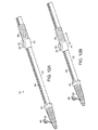
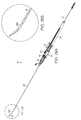
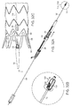
本発明の送達デバイス10の一態様を図1に示す。送達デバイス10は、近位端および遠位端を有するガイドワイヤカテーテル12を含む(図10、11)。送達デバイスおよびその構成要素に関して本明細書中で使用される用語として、「近位」は、該送達デバイスを操作する外科医に相対的に近いことを意味する。送達デバイスおよびその構成要素に関して本明細書中で使用される用語として、「遠位」は、該送達デバイスを操作する外科医から相対的に遠いことを意味する。プロテーゼ、ステントグラフトおよび構成要素に関して本明細書中で使用される用語として、「近位」は、患者の心臓に相対的に近いことを意味する。プロテーゼ、ステントグラフトおよび構成要素に関して本明細書中で使用される用語として、「遠位」は、患者の心臓から相対的に遠いことを意味する。図1に戻って、送達デバイス10は、ガイドワイヤカテーテル(示さず)の周囲に伸長する送達アセンブリ18を含む。送達アセンブリ18は、主要な長手軸22を有するハンドルボディ20、近位端24および遠位端26を含む。送達カテーテル28(図9)は、ハンドルボディ20の遠位端26内からガイドワイヤカテーテル(示さず)の周囲に伸長する遠位端30(図27A)を有する。押し棒32は、ガイドワイヤカテーテル12の周囲および送達カテーテル28(図10、11)内に伸長する。押し棒32は、ピン192(図25)でハンドルボディの近位にある押し棒32の近位端34においてガイドワイヤカテーテル12に固定される。再度図1を参照すると、近位ハンドル36は、ハンドルボディ20の周囲に伸長し、軸方向で送達カテーテル28に固定される。近位ハンドル36は選択的に押し棒32に固定され、ここで近位ハンドル36は、ハンドルボディ20の周囲で回転可能であり、近位ハンドル36のハンドルボディ20の周囲の回転は、図12Aと図12Bの比較によりわかるように、長手軸22に沿った送達カテーテル28の長手方向の移動、および選択的にハンドルボディ20に対する押し棒32の長手方向の移動に変換される。ハンドルボディ20における第1のロック機構38(図15)は、選択的に、近位ハンドル36(図12Aおよび12B)と押し棒32を嵌合する。
One embodiment of the
遠位ハンドル40は、ハンドルボディ20の遠位端26でハンドルボディ20の周囲に伸長し、第1のロック機構38の転位ノブ42の遠位にある(図15)。遠位ハンドルノーズ44(図1)は、遠位ハンドル40から遠位に伸長し、被験体に脈管プロテーゼを植え込む際に、必要な場合は溶液供給源(示さず)と送達デバイス10の内部構成要素の間の液体連絡を提供して、被験体内で、送達デバイス10の構成要素と脈管プロテーゼ(示さず)の間の接触を水和する(hydrate)ためのフラッシュポート(flush port)46を含む。外部カテーテル48は、遠位ハンドルノーズ44(図1)から伸長する。
The
アクチュエータ80は、近位ハンドル36に連結され、近位ハンドル36は、アクチュエータ80のハウジング81における押しボタン82を、ハンドルボディ20により画定されるスロット84と整列させたままにしながら、ハンドルボディ20の周囲で回転し得る。アクチュエータ80の押しボタン82を押し下げることで、近位ハンドル36はハンドルボディ20から選択的に分離され、それにより近位ハンドル20の回転は、長手軸22に沿ったハンドルボディ20に対する送達カテーテル12の長手方向の移動とは独立するようになる。
図2に見られるように、駆動軸88により、転位ノブ42が駆動ギア86に連結される。駆動軸88は、近位端90および遠位端92を有し、ハンドルボディ20(示さず)の内部に沿って進む(run)。図3に見られるように、一態様において、中間ギア94Aにより、転位ノブ42が駆動軸88に連結され、ハンドルボディ20の周囲の転位ノブ42の回転は、中間ギア94Aによる転位ノブ42と駆動軸88の間の連結により、駆動軸88の回転を起こす。この態様において、転位ノブ42は、直接連結とは反対に、駆動軸88に間接的に連結される。「直接連結」は、お互いの直接的な接触である。転位ノブ42は、図1に示されるように、ハンドルボディ20の遠位端26に固定された遠位ハンドル40に回転可能に連結される。
As seen in FIG. 2, the
図4および5に示す別の態様において、転位ノブ42と駆動軸88の間の連結は、中間ギア94Bと同軸上の減速ギア96に連結された中間ギア94Bでのギア減速を含み、ここで減速ギア96は、駆動軸88に同軸上で連結されたコネクトギア98に連結される。ギア減速により、駆動軸88に対する転位ノブ42の回転率は、減速ギア96およびコネクトギア98の相対的な寸法により制御され得る(図5、6、7)。典型的に、転位ノブ42:駆動軸88の回転率または減速率は、約1:2〜約1:6の比である。減速ギア96とコネクトギア98の関係は、図6においてより詳細に見ることができる。
In another embodiment shown in FIGS. 4 and 5, the connection between the
図7においてより詳細に見られるように、送達カテーテル28は、ハンドルボディ20、遠位ハンドル40および遠位ハンドルノーズ44を通って伸長する。再度図5を参照すると、外部カテーテル48は、基部102に連結され、外部カテーテル48はハンドルボディ20とは独立して回転可能である。図8に示されるように、収縮リング(constricting ring)104が、送達カテーテル28に沿ってハンドルボディ20内に伸長する。図8および9に示されるように、収縮リング104は、スロット84の幅よりも大きい外径を有し、それにより収縮リング104は、送達カテーテル28上(on delivery catheter 28)に近位ハンドル36により長手方向の圧縮力がかかって、送達カテーテル28が曲がり(buckle)それによりスロット84を通ってハンドルボディ20の外側に移動することを防ぐ。収縮リング104はまた、送達カテーテル28の外径よりもわずかに小さい内径を有し、収縮リング104は、送達カテーテル28に対する締まりばめを有するので、収縮リング104は、指示された場合は送達カテーテル28に沿って長手方向に移動し得るが、そうでなければ送達カテーテルに対して定位置に維持される。ハンドルボディ20内で、ギアラック106が長手方向に伸長する。ハンドルボディ20の遠位端のピン108は、ハンドルボディ20の遠位端26から伸長し、転位ノブ42のスロット110、112、114内に選択的に差し込まれる。転位ノブ42は、ハンドルボディ20に沿って長手方向に移動可能であり、転位ノブ42のスロット110、112、114のいずれか内にピン108の位置を移動させるように転位ノブ42を回転することを可能とするのに十分な程度に、ハンドルボディ20の周囲で回転可能であり、それにより中間ギア94の回転が起こる。結果的に、駆動軸88は、駆動軸88の長手軸116の周囲で回転する。転位ノブ42は、ばね118(図7)により、ピン108に偏る。
As seen in more detail in FIG. 7, the
図9に見られるように、ギアラック106および駆動軸88は、スロット84の長さを伸ばす。図10は、駆動軸88、押し棒32および第1のロック機構38の関係を示す。押し棒32は、第1のロック機構38を通って伸長し、第1のロック機構38は、第1のロック機構38の駆動ギア86における駆動軸88と嵌合する。第1のロック機構38は、遠位ベアリング120で近位ハンドル(示さず)に対して固定され、該ベアリングを通って押し棒32が伸長する。遠位ベアリング120は、ピン122により第1のロック構成要素ハウジング150に連結される。第1のロック機構38の第1のロック構成要素124は、遠位端126において遠位ベアリング120に固定され、近位端128で駆動ギア86に連結され、駆動軸88の回転およびその結果の駆動ギア86の回転により、第1のロック構成要素124がさらに巻かれる(coil)か、またはその巻きが低減され、ロック機構38、結果的に近位ハンドル(示さず)と押し棒32の嵌合または分離がそれぞれもたらされる。図12Aと12Bの比較により見られるように、第1のロック機構38を押し棒32と嵌合した場合、駆動軸88に沿った近位ハンドル(示さず)、したがってハンドルボディ20の長手方向の移動は、駆動軸88およびハンドルボディ20に沿った押し棒32の長手方向の移動を引き起こす。
As seen in FIG. 9, the
再度図10、11を参照すると、駆動軸88は、駆動軸88の近位端90で第2の近位ロック構成要素ハウジング152の一部になる駆動軸ベアリング130において、ハンドルボディ20(図9)に回転可能に固定される。第2のロック機構132は、駆動軸88の近位端90で駆動軸88と嵌合し、機構ベアリング136(図11)と回転可能に嵌合する変換ギア(translating gear)134を含み、該機構ベアリング136は、近位ベアリング138(図10)および遠位ベアリング140(図11)を含み、ピン142でハンドルボディ20に固定される。近位ベアリング138は、放射状および軸方向でハンドルボディ20に固定される。遠位ベアリング140は、軸方向でハンドルボディ20に固定される。第2のロック機構132の第2のロック構成要素144は、第2のロック構成要素144の近位端146で近位ベアリング138の1つと嵌合し、第2のロック構成要素144の遠位端148で変換ギア134と嵌合し、駆動軸88の回転、結果的に変換ギア134の回転により、第2のロック構成要素144と押し棒32を締めて嵌合させるか、または緩めて分離させる。押し棒32と嵌合する場合、第2のロック構成要素144は、押し棒32を、ハンドルボディ(示さず)に相対的な位置に固定させる。押し棒32から緩められて分離される場合、押し棒32は、ハンドルボディ(示さず)に対して長手方向に移動可能である。第1のロック構成要素124と第2のロック構成要素144の向きは逆方向であり、一方向の駆動軸88の回転により、第1のロック構成要素124および第2のロック構成要素144のそれぞれと押し棒32との嵌合および分離が同時に生じる。押し棒32からの第1のロック構成要素124の分離は、転位ノブ42のスロット110でピン108により画定された第1の位置から、転位ノブ42の第2のスロット112でピン108により画定された第2の位置112への転位ノブ42の移動により引き起こされる(図9)。転位ノブ42の第1の位置から第2の位置への同様の移動は、同時に第2のロック構成要素144と押し棒32の嵌合を引き起こし、それにより押し棒32は、ハンドルボディ20の長手軸116に沿った近位ハンドル36の移動とは関係なく、第2のロック構成要素144でハンドルボディ20に相対的な位置で固定される。再度図8および9を参照すると、転位ノブ42の位置を決定することで、ピン108は転位ノブ42の第1のスロット110および第2のスロット112の間の中間スロット114に位置し、第1のロック構成要素124および第2のロック構成要素144の両方の押し棒32からの分離が生じる。
Referring again to FIGS. 10 and 11, the
図11に見られるように、第1のロック構成要素ハウジング150は、第1のロック構成要素124および駆動軸88の側方の移動を固定し、第2のロック構成要素ハウジング152は、駆動軸88の近位端90に対する第2のロック構成要素144およびベアリング138、140それぞれの位置を固定する。さらに図11にも見られるように、頂部解放カテーテル154は押し棒32内で伸長し、ガイドワイヤカテーテル12は頂部解放カテーテル154内で伸長する。
As seen in FIG. 11, the first
図12Aおよび12Bは、ハンドルボディ20に沿ったアクチュエータ80および近位ハンドル36の相対的な移動を示す。図12Aおよび12Bに示されるように、押しボタン82が第1の位置にある場合、ハンドルボディ20の周囲の近位ハンドル36の回転は、ハンドルボディ20に沿った近位ハンドル20およびアクチュエータ80の長手方向の移動を引き起こす。押しボタン82を、アクチュエータハウジング81と本質的に同じ高さ(flush)の第2の位置に押し下げる際に、近位ハンドル36の回転は、ハンドルボディ20に沿った近位ハンドル36またはアクチュエータの長手方向の移動を引き起こさない。むしろ、近位ハンドル36およびアクチュエータ80は、近位ハンドル36をハンドルボディ20の周囲で回転させることなく、ハンドルボディ20に沿って移動可能である。
12A and 12B show the relative movement of the
図13〜15に見られるように、近位ハンドル36の歯156は、連結ギアアセンブリ158の上部連結ギア160と嵌合する。連結ギアアセンブリ158は、ピニオンギアアセンブリ164と嵌合する。連結ギアアセンブリ158の下部連結ギア162は、ピニオンギアアセンブリ164の上部ピニオンギア166と嵌合する。ピニオンギアアセンブリ164は、スロット84を通って第1のロック構成要素ハウジング150(図11)に連結する。連結ギアアセンブリ158とピニオンギアアセンブリ164は、図1に関して参照されるアクチュエータ80の構成要素である。図16は、(ハウジング81または押しボタン82を有さない)第1のロック構成要素ハウジング150および第2のロック構成要素ハウジング152の図1のアクチュエータ80の透視図である。
As seen in FIGS. 13-15, the
図17に見られるように、上部ピニオンギア166は、下部ピニオンギア168と同軸を有し、下部ピニオンギア168は、ギアラック106と嵌合する。再度図16および17を参照すると、送達カテーテル28は、第1のロック構成要素ハウジング150に連結されて、第1のロック構成要素124が押し棒32と嵌合するかどうかに関係なく、図1に示されるように、近位ハンドル36およびアクチュエータ80の移動に伴って、ハウジング150に沿って長手方向に移動する。そのため、上部ピニオンギア166が下部ピニオンギア168と嵌合する場合、(図1に示されるように)ハンドルボディ20の周囲の近位ハンドル36の回転は、連結ギアアセンブリ158(図13)の回転、結果的にピニオンギアアセンブリ164(図13)の回転、およびギアラック106(図16および17)に沿ったピニオンギアアセンブリ164(図13)の移動、ならびにハンドルボディ20に沿った近位ハンドル36(図1)およびアクチュエータ80(図17)の移動を引き起こす。さらに、第1のロック構成要素124が押し棒32と嵌合しながら、近位ハンドル36が回転することは、ハンドルボディ20に沿った押し棒32の長手方向の移動を引き起こす。全ての場合において、ハンドルボディ20に沿った近位ハンドル36およびアクチュエータ80の移動は常に一緒に起こり、ハンドルボディ20に沿った送達カテーテル28の長手方向の移動を引き起こす。
As can be seen in FIG. 17, the
しかしながら、以下にさらに説明されるように、中心ピン170を押し下げることにより、下部ピニオンギア168から上部ピニオンギア166が分離する。上部ピニオンギア166が下部ピニオンギア168から分離される場合、ハンドルボディ20の周囲の近位ハンドル36の回転は、ハンドルボディ20に沿った近位ハンドル36およびアクチュエータ80の長手方向の移動を引き起こさない。さらに、ハンドルボディ20に沿った近位ハンドル36およびアクチュエータ80の長手方向の移動は、ハンドルボディ20の周囲で近位ハンドル36を回転させる(図1、12Aおよび12B)ことなく、ハンドルボディ20に沿って近位ハンドル36およびアクチュエータ80を単純に移動させることにより得ることができる。
However, as described further below, depressing the
図18は、ハンドルボディ20の近位端24内の第2のロック構成要素ハウジング152およびベアリング138と140の間に伸長する第2のロック構成要素144の配置を示す。上述のように、駆動軸88(図10、11)の回転による変換ギア134の回転は、第2のロック構成要素144と、第2のロック構成要素144を通って伸長する押し棒32との嵌合または分離、結果的に押し棒32と、ハンドルボディ20の近位端24との嵌合および分離を引き起こす。
FIG. 18 shows the arrangement of the second
図19は、アクチュエータ80(図1)の連結ギアアセンブリ158およびピニオンギアアセンブリ164の別の透視図である。
FIG. 19 is another perspective view of
図20に示される代替的な態様として、押しボタン82は、上部ピニオンギア166を通って伸長する中心ピン170の頂部に維持される。図20および21においても見られるように、下部ピニオンギア168は、ギアラック106と嵌合し、上部ピニオンギア166と同軸上に整列される下部ピニオンギア168と同軸上に整列されるピニオンギア伸長部(extension)169を含む。ピニオンギア168の下部172は、第1のロック構成要素ハウジング150(図11)により画定される開口174(図11)中に伸長し、それにより第1のロック構成要素ハウジング150(図11)、遠位ベアリング120(図11)、第1のロック構成要素124および駆動ギア86(これらの全ては先の態様において図11に示される)に対するピニオンギアアセンブリ164の位置が固定される。
As an alternative embodiment shown in FIG. 20, the
図21は、下部ピニオンギア168と、ギアラック106および中心ピン170の円錐台部176の嵌合を示す透視図である。図22および23に見られるように、ピニオンギア伸長部169により画定された開口180を通ってボールベアリング178が伸長し、図22に示すように中心ピン170が伸長された位置にある場合、中心ピン170の円錐台部176は、ボールベアリング178を、外側に動かし(force)て、上部ピニオンギア166(図21および22)により画定された開口182(図21)と干渉する関係にし、それにより上部ピニオンギア166と下部ピニオンギア168を嵌合させる。図23に示されるようにボタン82(図1)を押し下げることにより中心ピン170を発動させる場合、下部ピニオンギア168(図22)に対する上部ピニオンギア166(図22)の回転によりボールベアリング178が内側に動かされ、上部ピニオンギア166は、これ以上下部ピニオンギア168と嵌合しなくなる。中心ピン170は外側の位置に偏るので、中心ピン170の基部(図22または23には示さず)に配置されたばね184により、上部ピニオンギア166は、下部ピニオンギア168と嵌合するように方向づけられる。
Figure 21 is a
図32Cに見られるように、ガイドワイヤカテーテル12の遠位端16で、ノーズコーン50が、ガイドワイヤカテーテル12に固定される。ノーズコーン50の近位の送達デバイス10内に、脈管プロテーゼ構成要素58が配置される(図27A)。
As seen in FIG. 32C, a
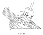
図25および26はそれぞれ、本発明の近位クラスプアセンブリ184構成要素の透視図およびカッタウェイ図を示す。図25に見られるように、外部継手186は、押し棒32の近位端34に沿って摺動可能である。固定された構成要素188は、ピン192によりガイドワイヤカテーテルの近位端に固定される。外部継手186および固定された構成要素188は、つなぎ目190で、噛み合う(mating)関係にある。外部継手186内のばね194は、固定された構成要素188に対して外部継手186に偏る。近位クラスプアセンブリ184は、図25、28Bに示される第1の位置から、図32に示されるように、外部継手186のいずれかの面上の凸縁部(tongue)196に圧力をかけ、外部継手186を90°回転させる程度に十分に外部継手186を遠位に方向づけ、次いで外部継手186を引っ込めて、外部継手186の凸縁部196を、固定された構成要素188の凸縁部198の間に整列させることにより第2の位置に移動される。図25に示される第1の位置から図32Bに示される位置への外部継手186の移動により、頂部クラスプアセンブリ52が開かれ、それにより近位捕捉構成要素が、図31Bに示される頂部クラスプアセンブリ52の遠位捕捉構成要素56と噛み合う関係にある第1の位置から、図32Cに示される第2の位置へと引っ込み、近位捕捉構成要素54は、もはや遠位捕捉構成要素56と噛み合う関係ではなくなる。近位捕捉構成要素54(図31B)を遠位捕捉構成要素56(図31B、32C)から分離するための、固定された構成要素188に対する近位クラスプアセンブリ184(図25、28B、32B)の外部継手186の近位の移動は、脈管プロテーゼ構成要素58の近位端60で、ステント66の頂部68を解放させる。
Figures 25 and 26 show perspective and cutaway views, respectively, of the
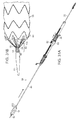
図27A〜27Cは、本発明の送達デバイス10の一部の断面図であり、送達デバイス10の遠位端202内で展開されていない状態の脈管プロテーゼ構成要素58を示す。具体的に、図27Aに示すように、脈管プロテーゼ構成要素58は、送達シース200内にある。脈管プロテーゼ構成要素58の遠位端62は、控え壁(buttress)204に隣接する。次いで、図27Aに示されるように、控え壁204は、遠位端206で押し棒32と噛み合い、頂部クラスプアセンブリ52が閉じられた位置にある場合、脈管プロテーゼ構成要素58の近位端60は、近位ステント66の頂部68で、頂部クラスプアセンブリ52により捕捉される。頂部クラスプ(class)アセンブリ52は、ガイドワイヤカテーテル12の遠位端16で遠位捕捉構成要素56を含み、近位捕捉構成要素54は、遠位捕捉構成要素56と噛み合い得る関係にあり、頂部解放カテーテル154の遠位端210に取り付けられる。頂部解放カテーテル154はガイドワイヤカテーテル12の周囲に伸長し、頂部解放カテーテル154とガイドワイヤカテーテル12の両方は、脈管プロテーゼ構成要素58と押し棒32を通って近位クラスプアセンブリ184(図26)まで伸長する。送達シース200は、その近位端で送達カテーテル28の遠位端30に(at distal end 30)固定され、図27Cに見られるように、脈管プロテーゼ構成要素58の周囲を頂部クラスプアセンブリ52まで伸長する。図27に戻ると、ガイドワイヤカテーテル12の遠位で、ノーズコーン50が、頂部クラスプアセンブリ52の遠位捕捉構成要素56に固定される。外部カテーテル48は、遠位ハンドルノーズ44(図1)から、送達カテーテル28および送達シース200の周囲を、ノーズコーン50まで伸長する。
27A-27C are cross-sectional views of a portion of the
図28A〜33Bに示されるように、本発明の送達デバイスを使用して被験体の治療部位まで脈管プロテーゼを送達するための方法は、プロテーゼ58を、プロテーゼ58の近位端60で頂部クラスプアセンブリ52に備え付けて、脈管プロテーゼ58を進ませる工程を含む。近位頂部クラスプアセンブリ184は、図28Bに示される第1の位置にあり、頂部クラスプアセンブリ52は閉じている(図31B)。近位クラスプアセンブリ184が第1の位置にある場合、脈管プロテーゼ58の頂部は頂部クラスプアセンブリ52において固定される。次いで、頂部クラスプアセンブリ52は、ガイドワイヤカテーテル12の遠位端16に固定され、ピン108がスロット110内にある場合(図28C)、転位ノブ42は第1の位置にあり、押し棒32が、近位ハンドル36の長手方向の移動に伴って移動される。プロテーゼ58は、近位ハンドル36を、遠位端26を有する送達デバイス10のハンドルボディ20の周囲で第1の方向に回転することにより、被験体の脈管治療部位の遠位の位置まで進められ、その中を通ってガイドワイヤカテーテル12が伸長する。ガイドワイヤカテーテル12は、押し棒32内に配置され、またハンドルボディ20を通って伸長し、ここでガイドワイヤカテーテル12は、ガイドワイヤカテーテル12の近位端または押し棒32などの位置で、ピン192(図25)により押し棒32に固定され、近位ハンドル36を回転させることで、ハンドルボディ20に沿ってガイドワイヤカテーテル12および押し棒32の長手方向の移動が生じ、それにより、図29A〜29Bに見られるように、プロテーゼ58が、外部カテーテル48から少なくとも部分的に進められる。選択的に、アクチュエータ80の押しボタン82を押し下げることで、近位ハンドル36の回転と、ハンドルボディ20に沿った近位ハンドル36の長手方向への移動が分離され得、それにより、ハンドルボディ20の周囲で近位ハンドル36を回転させることなく、脈管プロテーゼ58を、被験体の脈管治療部位まで手動で進めることが可能になる。
As shown in FIGS. 28A-33B, a method for delivering a vascular prosthesis to a treatment site in a subject using the delivery device of the present invention includes a
転位ノブ42を第1の位置(ここでは第1のロック構成要素124(図10、11)は、近位ハンドル36を押し棒32に固定する)から第2の位置まで転位させて、それにより第1のロック構成要素124(図10、11)が、近位ハンドル36と押し棒32を分離し、第2のロック構成要素144(図10、11)が、押し棒32と、ハンドルボディ20の近位端24でハンドルボディ20を嵌合させる。
The
図31Aおよび31Bに見られるように、次いで、アクチュエータ押しボタン82を押し下げずに近位ハンドル36を第2の方向に回転させ得、遠位端30(図24A)を有し、かつ押し棒32の周囲に伸長する送達カテーテル28を、押し棒32に沿って引き抜き、送達カテーテルの遠位端から伸長する送達シース200(図4〜9)を、プロテーゼ52の周囲から少なくとも部分的に引っ込める。選択的に、アクチュエータ80の押しボタン82を押し下げ、それにより近位ハンドル36の回転と、ハンドルボディ20を分離させ得、図32Aに見られるように、ハンドルボディ20の周囲で近位ハンドル36を回転させることなく、脈管プロテーゼ58から送達シース200を完全に引っ込め得る。
As seen in FIGS. 31A and 31B, the
図32Bに示されるように、次いで、外部継手186を押し付けて外部継手186を最初に遠位に移動させることにより近位クラスプアセンブリ184を発動させて、次いで外部継手186を90°回転させ、その後、外部継手186を、第2の位置まで引っ込め、それにより押し棒32内の頂部解放カテーテル154(図10、11)を引っ込め、遠位捕捉構成要素56から近位捕捉構成要素54を引っ込める。脈管プロテーゼ58の近位端60で、ステント66の頂部68を、頂部クラスプアセンブリ52から解放し、それにより、図32Cに見られるように、送達デバイス10からプロテーゼ58を解放させる。次いで、転位ノブ42を、第2の位置から第3の位置まで移動させ(図33Bに見られるように、ここではピン108は第1のスロット110と第2のスロット112の間のスロット114に配置される)、それによりハンドルボディ20から押し棒32を分離させる。図33Aに見られるように、次いで、ハンドルボディ20を通って押し棒32を引くことにより、押し棒32およびガイドワイヤカテーテル12を脈管プロテーゼ58から引き抜き、それにより、治療部位への脈管プロテーゼ58の送達が完了する。
32B, the
本発明は、その例示態様に関して、特に示され、記載されてきたが、形態および詳細における種々の変更が、添付の特許請求の範囲に包含される発明の範囲から逸脱することなく、本発明においてなされ得ることが、当業者には理解されよう。 Although the invention has been particularly shown and described with respect to exemplary embodiments thereof, various changes in form and detail may be made in the invention without departing from the scope of the invention as encompassed by the appended claims. Those skilled in the art will understand that this can be done.
本明細書に引用される全ての参照の関連部分および米国特許第8,070,790号および米国特許出願第12/459,387号(公開番号20100030255)および同12/723,431号(公開番号20100234932)は、それらの全体において参照により援用される。 The relevant portions of all references cited herein and U.S. Patent No. 8,070,790 and U.S. Patent Application Nos. 12 / 459,387 (publication number 20100030255) and 12 / 723,431 (publication number 20100234932) are incorporated in their entirety. Incorporated by reference.
Claims (16)
b) ガイドワイヤカテーテルの周囲に伸長する送達アセンブリ(18)
を含む送達デバイス(10)であって、
該送達アセンブリは、
i) 主要な長手軸(22)、近位端(24)および遠位端(26)を有するハンドルボディ(20)、
ii) 遠位端(30)を有し、ハンドルボディ(20)の遠位端内からガイドワイヤカテーテル(12)の周囲に伸長する送達カテーテル(28)、
iii) ガイドワイヤカテーテル(12)の周囲で、送達カテーテル(28)内に伸長する押し棒(32)、ここで、該押し棒(32)は、ハンドルボディ(20)の近位にあるガイドワイヤカテーテル(12)の近位端(24)でガイドワイヤカテーテル(12)に固定される、
iv) ハンドルボディ(20)の周囲に伸長し、かつ送達カテーテルに軸方向で固定される近位ハンドル(36)、ここで、該近位ハンドルは、押し棒に選択的に固定され、該近位ハンドルは、ハンドルボディの周囲で回転可能であり、ハンドルボディの周囲の近位ハンドルの回転は、送達カテーテルの長手方向の移動、および選択的にハンドルボディに対する押し棒の長手方向の移動に変換される、ならびに
v) 押し棒(32)と選択的に嵌合する、ハンドルボディにある第1のロック機構(38)、これにより、ハンドルボディ(20)の主要な長手軸(22)に沿った近位ハンドル(36)の長手方向の移動は、主要な長手軸(22)に沿った押し棒(32)の長手方向の移動を引き起こす、
を含む、送達デバイス(10)。 a) a guidewire catheter (12) having a proximal end and a distal end; and
b) A delivery assembly (18) extending around the guidewire catheter
A delivery device (10) comprising:
The delivery assembly comprises
i) a handle body (20) having a major longitudinal axis (22) , a proximal end (24) and a distal end (26 ) ;
ii) a delivery catheter (28) having a distal end (30) and extending around the guidewire catheter (12) from within the distal end of the handle body (20 ) ;
iii) a push rod (32) extending around the guide wire catheter (12) and into the delivery catheter (28 ) , wherein the push rod (32) is proximal to the handle body (20) is fixed to the guide wire catheter (12) at the proximal end of the catheter (12) (24),
iv) a proximal handle (36) extending around the handle body (20) and axially secured to the delivery catheter, wherein the proximal handle is selectively secured to the push rod and the proximal The position handle is rotatable around the handle body, and rotation of the proximal handle around the handle body translates into a longitudinal movement of the delivery catheter and optionally a longitudinal movement of the push rod relative to the handle body As well as
v) you selectively mate with push and rod (32), a first locking mechanism on the handle body (38), thereby the near along the main longitudinal axis of the handle body (20) (22) Longitudinal movement of the displacement handle (36) causes longitudinal movement of the push bar (32) along the major longitudinal axis (22),
A delivery device (10) comprising:
該送達デバイスが、
a) ハンドルボディの主要な長手軸に沿って伸長するギアラック(106);
b) 近位ハンドル末端の歯と嵌合する連結ギア(160)、ここで、該連結ギアは、近位ハンドルの回転の軸と直交する軸の周囲で回転可能である;ならびに
c) ギアラック(106)および連結ギア(160)と嵌合するピニオンギアアセンブリ(164)
をさらに含み、
ハンドルボディ(20)の周囲の近位ハンドル(36)の回転は、送達カテーテル(28)の長手方向の移動、および選択的にハンドルボディ(20)に対する押し棒(32)の長手方向の移動に変換され、アクチュエータ(80)が、ピニオンギアアセンブリ(164)の回転から連結ギア(160)の回転を選択的に分離し、それにより、ハンドルボディ(20)に沿った近位ハンドル(36)の長手方向の移動から、近位ハンドル(36)の回転が選択的に分離される、請求項2記載の送達デバイス。 A delivery device that includes a distal end that defines a tooth (156) that moves laterally relative to a major longitudinal axis of the handle body when the proximal handle is rotated about the handle body. And
The delivery device comprises:
a) a gear rack (106) extending along the main longitudinal axis of the handle body;
b) a proximal handle end of the teeth and mating connection gear (160), wherein the connecting gear is rotatable about an axis which axis Cartesian rotation of the proximal handle; and
c) Pinion gear assembly (164) mating with gear rack (106) and connecting gear (160 )
Further including
Rotation of the proximal handle (36) around the handle body (20) causes a longitudinal movement of the delivery catheter (28) and optionally a longitudinal movement of the push bar (32) relative to the handle body (20) . Converted, the actuator (80) selectively decouples the rotation of the coupling gear (160) from the rotation of the pinion gear assembly (164) , thereby enabling the proximal handle (36) along the handle body (20 ) . The delivery device according to claim 2, wherein rotation of the proximal handle (36) is selectively separated from longitudinal movement.
a) ハンドルボディの周囲で伸長し、近位ハンドルに回転可能に連結されるアクチュエータハウジング(81)、ここで、該アクチュエータハウジングは、近位ハンドルがハンドルボディの周囲で回転する間、ハンドルボディの周囲で回転することなく、ハンドルボディに沿って移動可能となる;
b) アクチュエータハウジングにある押しボタン(82);
c) ピニオンギアアセンブリ(164)と同軸上の同軸開口を画定し、かつ該同軸開口から側方に伸長する少なくとも1つの側方開口を画定するピニオンギア伸長部(169);
d) 少なくとも部分的に側方開口内に配置され、かつ動かされてピニオンギア伸長部を超えて放射方向に伸長する場合に連結ギアおよびピニオンギアの相対的な回転を固定するボールベアリング;ならびに
e) ハンドルボディの主要な長手軸から放射方向に外側に偏り、押しボタンに隣接する中心ピン(170)の円錐台部(176)
を含む、送達デバイスであって、
該中心ピン(170)の円錐台部(176)は、側方開口を通ってボールベアリングを放射方向に外側に動かして、外側への偏りにより、連結ギアおよびピニオンギアの相対的な回転を固定し、それにより、近位ハンドルがハンドルボディの周囲で回転される場合にハンドルボディに沿った近位ハンドルの長手方向の移動を生じ、押しボタンが押し下げられた場合にピニオンギアから連結ギアを選択的に分離し、ハンドルボディに沿った近位ハンドルの長手方向の移動から近位ハンドルの回転を選択的に分離する、請求項3記載の送達デバイス。 The actuator
a) an actuator housing (81) that extends around the handle body and is rotatably coupled to the proximal handle, wherein the actuator housing is disposed on the handle body while the proximal handle rotates about the handle body. Can move along the handle body without rotating around it;
b) Oh Ru push button to the actuator housing (82);
c) a pinion gear extension (169) defining a coaxial opening coaxial with the pinion gear assembly (164) and defining at least one lateral opening extending laterally from the coaxial opening;
d) a ball bearing disposed at least partially within the side opening and securing the relative rotation of the coupling gear and the pinion gear when moved to extend radially beyond the pinion gear extension; and
e) frustoconical part (176) of central pin (170) offset radially outward from the main longitudinal axis of the handle body and adjacent to the push button
A delivery device comprising:
Frustoconical portion of the central pin (170) (176) is moved out on the ball bearings in a radial direction through the side opening, the bias toward the outside, fixing the relative rotation of the coupling gear and the pinion gear Thereby causing longitudinal movement of the proximal handle along the handle body when the proximal handle is rotated around the handle body, and selecting a coupling gear from the pinion gear when the push button is depressed 4. The delivery device of claim 3, wherein the delivery device selectively separates and selectively separates rotation of the proximal handle from longitudinal movement of the proximal handle along the handle body.
a) ハンドルボディ(20)の周囲で回転可能であり、かつ転位ノブ(42)がハンドルボディ(20)の周囲で回転される場合にハンドルボディ(20)の主要な長手軸(22)に横方向に移動する転位ノブ(42)の内側に沿った歯(156)を画定する、遠位ハンドル(40)にある転位ノブ(42)、ここで該転位ノブ(42)は、ハンドルボディ(20)に対して少なくとも第1の固定された位置および第2の固定された位置を有する;
b) 近位端(90)および遠位端(92)を有する駆動軸(88)、ここで該遠位端(92)は、転位ノブ(42)の歯(156)と嵌合し、駆動軸(88)の主要な長手軸に沿って伸長する歯を画定する;
c) 駆動軸(88)に沿った歯と嵌合する歯を画定する、駆動軸(88)に沿った駆動ギア(86)、ここで該転位ノブ(42)は、転位ノブ(42)の全ての位置で駆動ギア(86)と嵌合される;ならびに
d) 押し棒(32)の周囲に伸長する第1のロック構成要素(124)、ここで、該第1のロック構成要素(124)は、近位ハンドル(36)および駆動ギア(86)に連結される、
を含み、
転位ノブ(42)の第1の固定された位置において、第1のロック構成要素(124)は、近位ハンドル(36)と押し棒(32)を嵌合し、第1の固定された位置から第2の固定された位置への転位ノブ(42)の回転により、駆動軸(88)の回転が生じ、次いで、駆動軸の回転により、駆動ギア(86)の回転および押し棒(32)からの第1のロック構成要素(124)の分離が生じ、それにより、近位ハンドル(36)がハンドルボディ(20)の主要な長手軸(22)に沿って移動される場合、押し棒(32)に対するハンドルボディ(20)の主要な長手軸(22)に沿った送達カテーテル(28)の独立した移動が可能になる、請求項4記載の送達デバイス。 A delivery device further comprising a distal handle (40) at a distal end of the handle body, wherein the first locking mechanism (38) comprises:
rotatable around a) the handle body (20), and transverse to the main longitudinal axis of the handle body (20) (22) when it is rotated around the dislocation knob (42) is a handle body (20) defining a tooth (156) along the inner side of the dislocation knob moving in a direction (42), Ah Ru dislocation knob distal handle (40) (42), wherein the dislocation knob (42), the handle body ( 20) at least a first fixed position and a second fixed position ;
b) A drive shaft (88) having a proximal end (90) and a distal end (92) , wherein the distal end (92) engages and drives the teeth (156) of the displacement knob (42) Defining teeth extending along the major longitudinal axis of the axis (88) ;
c) defining a drive shaft (tooth teeth mate along 88), the drive gear along the drive shaft (88) (86), wherein the dislocation knob (42), rearrangement knob (42) Mated with drive gear (86) in all positions; and
The first locking element extending around the d) push rod (32) (124), wherein said first lock component (124), the proximal handle (36) and drive gear (86) Concatenated ,
Including
In the first fixed position of the shift knob (42) , the first locking component (124) engages the proximal handle (36) and the push rod (32) to form the first fixed position. Rotation of the shift knob (42) from the second to a fixed position results in rotation of the drive shaft (88) , which in turn causes rotation of the drive gear (86) and push rod (32). When the separation of the first locking component (124) from the substrate occurs so that the proximal handle (36) is moved along the main longitudinal axis (22) of the handle body (20) , the push rod ( The delivery device according to claim 4, which allows independent movement of the delivery catheter (28) along the major longitudinal axis (22 ) of the handle body (20 ) relative to 32) .
第2のロック機構(132)が、押し棒(32)の周囲に伸長し、ハンドルボディ(20)に固定され、かつ駆動軸(88)を介して転位ノブ(42)に連結され、
第1の位置から第2の位置への転位ノブ(42)の回転により、第2のロック機構(132)と押し棒(32)の間の嵌合が生じ、
それにより、近位ハンドル(36)が主要な長手軸(22)に沿って移動される場合、ハンドルボディ(20)に対する押し棒(32)の長手方向の移動が防がれる、請求項5記載の送達デバイス。 The delivery assembly (18) further comprises a second locking mechanism (132) ;
A second locking mechanism (132) extends around the push rod (32) , is fixed to the handle body (20) , and is connected to the displacement knob (42) via the drive shaft (88) ;
The rotation of the shift knob (42) from the first position to the second position results in a fit between the second locking mechanism (132) and the push bar (32) ,
6. The longitudinal movement of the push bar (32) relative to the handle body (20 ) is thereby prevented when the proximal handle (36) is moved along the main longitudinal axis (22). Delivery device.
頂部送達デバイスが、
a) 頂部クラスプアセンブリ(52)、ここで、該頂部クラスプアセンブリは、
i) ガイドワイヤカテーテル(12)の遠位端にある遠位捕捉構成要素(56)
ii) 遠位捕捉構成要素(56)と噛み合い得る関係にある近位捕捉構成要素(54)、および
iii) 近位端を有する頂部解放カテーテル(154)、ここで、該頂部解放カテーテル(154)は、ガイドワイヤカテーテル(12)の周囲で伸長し、近位捕捉構成要素(54)に固定される、
を有する;ならびに
b) 近位クラスプアセンブリ(184)、ここで、近位クラスプアセンブリは、
i) ガイドワイヤカテーテルの近位端にある固定された構成要素(188)、および
ii) 頂部解放カテーテル(154)の近位端にあり、かつ近位クラスプアセンブリ(184)の固定された構成要素と噛み合い得る関係にある外部継手(186)、
を有する、
を含み、
第1の位置から第2の位置への固定された構成要素(188)に対する外部継手(186)の移動により、頂部クラスプアセンブリ(52)の遠位捕捉構成要素(56)に対する近位捕捉構成要素(54)の相対的な移動が生じる、請求項6記載の送達デバイス。 A delivery device further comprising a top delivery device comprising:
The top delivery device is
a) Top clasp assembly (52) , wherein the top clasp assembly is
i) the guide wire distal acquisition component Ru Oh the distal end of the catheter (12) (56)
ii) a proximal capture component (54) in meshable relationship with the distal capture component (56 ) , and
iii) apex release catheter having a proximal end (154), wherein said top release catheter (154) is extended around the guide wire catheter (12) is secured to the proximal acquisition component (54) ,
Having; and
b) Proximal clasp assembly (184) , where the proximal clasp assembly is
i) a fixed component (188) at the proximal end of the guidewire catheter; and
ii) an external fitting (186) at the proximal end of the top release catheter (154) and in meshable relationship with a fixed component of the proximal clasp assembly (184 ) ;
Having
Including
Movement of the external coupling (186) relative to the fixed component (188) from the first position to the second position results in a proximal capture component relative to the distal capture component (56) of the top clasp assembly (52). The delivery device of claim 6, wherein relative movement of (54) occurs.
その位置では、第1のロック機構(38)および第2のロック機構(132)が押し棒(32)から分離され、
押し棒(32)が、押し棒(32)の長手方向の移動によりハンドルボディ(20)および近位ハンドル(36)に対して長手方向に移動され得、
それにより、ガイドワイヤカテーテル(12)が、近位ハンドル(36)およびハンドルボディ(20)とは独立して移動される、請求項7記載の送達デバイス。 The shift knob further includes a third position relative to the handle body (20) ;
In that position, the first locking mechanism (38) and the second locking mechanism (132) are separated from the push rod (32) ,
The push rod (32) may be moved longitudinally relative to the handle body (20) and the proximal handle (36) by longitudinal movement of the push rod (32) ;
8. The delivery device according to claim 7, wherein the guidewire catheter (12) is moved independently of the proximal handle (36) and the handle body (20) .
該送達デバイスが、ハンドルボディ(20)内の送達カテーテル(28)の周囲に伸長する複数の収縮リング(104)をさらに含み、
該収縮リング(104)が、スロット(110)の外径よりも大きい外径を有し、
該収縮リング(104)が、近位ハンドル(36)により送達カテーテル(28)に長手方向の圧縮力がかかって、送達カテーテル(28)が曲がり、それにより、スロット(110)を通ってハンドルボディ(20)の外側を移動することを防ぐ、請求項8記載の送達デバイス。 A delivery device in which a handle body (20) defines a slot (110) through which an actuator (80) extends;
The delivery device further comprises a plurality of contraction rings (104) extending around a delivery catheter (28) in the handle body (20) ;
The shrink ring (104) has an outer diameter greater than the outer diameter of the slot (110) ;
The contraction ring (104) is a delivery catheter (28) by a proximal handle (36) takes the longitudinal direction of the compression force, the delivery catheter (28) is bent, whereby the handle body through the slot (110) 9. A delivery device according to claim 8, which prevents movement outside (20) .
Applications Claiming Priority (3)
| Application Number | Priority Date | Filing Date | Title |
|---|---|---|---|
| US201261623235P | 2012-04-12 | 2012-04-12 | |
| US61/623,235 | 2012-04-12 | ||
| PCT/US2013/031702 WO2013154749A1 (en) | 2012-04-12 | 2013-03-14 | Vascular prosthetic delivery device and method of use |
Related Child Applications (1)
| Application Number | Title | Priority Date | Filing Date |
|---|---|---|---|
| JP2017210741A Division JP6556210B2 (en) | 2012-04-12 | 2017-10-31 | Vascular prosthesis delivery device and method of use |
Publications (3)
| Publication Number | Publication Date |
|---|---|
| JP2015512746A JP2015512746A (en) | 2015-04-30 |
| JP2015512746A5 JP2015512746A5 (en) | 2016-04-21 |
| JP6238959B2 true JP6238959B2 (en) | 2017-11-29 |
Family
ID=48045735
Family Applications (3)
| Application Number | Title | Priority Date | Filing Date |
|---|---|---|---|
| JP2015505761A Active JP6238959B2 (en) | 2012-04-12 | 2013-03-14 | Vascular prosthesis delivery device and method of use |
| JP2017210741A Active JP6556210B2 (en) | 2012-04-12 | 2017-10-31 | Vascular prosthesis delivery device and method of use |
| JP2019127644A Active JP6846470B2 (en) | 2012-04-12 | 2019-07-09 | Vascular prosthesis delivery device and usage |
Family Applications After (2)
| Application Number | Title | Priority Date | Filing Date |
|---|---|---|---|
| JP2017210741A Active JP6556210B2 (en) | 2012-04-12 | 2017-10-31 | Vascular prosthesis delivery device and method of use |
| JP2019127644A Active JP6846470B2 (en) | 2012-04-12 | 2019-07-09 | Vascular prosthesis delivery device and usage |
Country Status (7)
| Country | Link |
|---|---|
| US (5) | US8998970B2 (en) |
| EP (2) | EP3141223A1 (en) |
| JP (3) | JP6238959B2 (en) |
| CN (1) | CN104363862B (en) |
| BR (1) | BR112014025430A2 (en) |
| ES (1) | ES2618221T3 (en) |
| WO (1) | WO2013154749A1 (en) |
Families Citing this family (62)
| Publication number | Priority date | Publication date | Assignee | Title |
|---|---|---|---|---|
| US9198786B2 (en) | 2003-09-03 | 2015-12-01 | Bolton Medical, Inc. | Lumen repair device with capture structure |
| US20070198078A1 (en) | 2003-09-03 | 2007-08-23 | Bolton Medical, Inc. | Delivery system and method for self-centering a Proximal end of a stent graft |
| US20080264102A1 (en) | 2004-02-23 | 2008-10-30 | Bolton Medical, Inc. | Sheath Capture Device for Stent Graft Delivery System and Method for Operating Same |
| US11259945B2 (en) | 2003-09-03 | 2022-03-01 | Bolton Medical, Inc. | Dual capture device for stent graft delivery system and method for capturing a stent graft |
| US8292943B2 (en) | 2003-09-03 | 2012-10-23 | Bolton Medical, Inc. | Stent graft with longitudinal support member |
| US11596537B2 (en) | 2003-09-03 | 2023-03-07 | Bolton Medical, Inc. | Delivery system and method for self-centering a proximal end of a stent graft |
| US7763063B2 (en) | 2003-09-03 | 2010-07-27 | Bolton Medical, Inc. | Self-aligning stent graft delivery system, kit, and method |
| US8500792B2 (en) | 2003-09-03 | 2013-08-06 | Bolton Medical, Inc. | Dual capture device for stent graft delivery system and method for capturing a stent graft |
| CN102076281B (en) | 2008-06-30 | 2014-11-05 | 波顿医疗公司 | Systems and methods for abdominal aortic aneurysm |
| CN106551740B (en) | 2009-03-13 | 2020-03-27 | 波顿医疗公司 | System and method for deploying an endoluminal prosthesis at a surgical site |
| BR112014011353A2 (en) | 2011-11-11 | 2017-06-06 | Bolton Medical Inc | universal endovascular grafts |
| CN106420107B (en) | 2011-11-16 | 2019-02-05 | 波顿医疗公司 | The device and method of reparation for aortic branch blood vessel |
| US10376362B2 (en) | 2012-04-05 | 2019-08-13 | Medtronic Vascular Galway | Valve introducers with adjustable deployment mechanism and implantation depth gauge |
| WO2013154749A1 (en) | 2012-04-12 | 2013-10-17 | Bolton Medical, Inc. | Vascular prosthetic delivery device and method of use |
| US9539130B2 (en) * | 2012-10-29 | 2017-01-10 | Cook Medical Technologies Llc | Low profile stepped delivery system |
| US9439751B2 (en) | 2013-03-15 | 2016-09-13 | Bolton Medical, Inc. | Hemostasis valve and delivery systems |
| GB201323008D0 (en) | 2013-12-24 | 2014-02-12 | Amazentis As | Compounds and uses thereof |
| US9486350B2 (en) * | 2014-03-31 | 2016-11-08 | Medtronic Vascular, Inc. | Stent-graft delivery system having handle mechanism for two-stage tip release |
| CN103961194B (en) | 2014-05-21 | 2016-05-18 | 苏州茵络医疗器械有限公司 | A kind of high nerve intravascular stent induction system |
| CN106687074A (en) | 2014-09-23 | 2017-05-17 | 波顿医疗公司 | Vascular repair device and method of use |
| CN104546243B (en) * | 2015-01-04 | 2016-05-25 | 苏州茵络医疗器械有限公司 | Be hold by one hand intravascular stent induction system and the using method thereof of formula |
| US10758349B2 (en) | 2015-03-13 | 2020-09-01 | Medtronic Vascular, Inc. | Delivery device for prosthetic heart valve with capsule adjustment device |
| US10327899B2 (en) * | 2015-03-13 | 2019-06-25 | Medtronic Vascular, Inc. | Delivery device for prosthetic heart valve with capsule adjustment device |
| US11504236B2 (en) | 2015-03-13 | 2022-11-22 | Medtronic Vascular, Inc. | Delivery device for prosthetic heart valve with capsule adjustment device |
| CN113244032B (en) * | 2015-09-18 | 2023-06-27 | 泰尔茂株式会社 | Pushable implant delivery system |
| WO2017156352A1 (en) * | 2016-03-11 | 2017-09-14 | Medtronic Vascular Inc. | Delivery device for prosthetic heart valve with capsule adjustment device |
| US20170281382A1 (en) | 2016-04-05 | 2017-10-05 | Bolton Medical, Inc. | Delivery systems with introducer and distal sheaths and methods of use |
| ES2830748T3 (en) | 2016-04-05 | 2021-06-04 | Bolton Medical Inc | Stent grafting with internal tunnels and fenestrations |
| WO2017176678A1 (en) | 2016-04-05 | 2017-10-12 | Bolton Medical, Inc. | Delivery device with filler tubes |
| JP6986522B2 (en) | 2016-05-25 | 2021-12-22 | ボルトン メディカル インコーポレイテッド | Stent graft |
| US20180206972A1 (en) | 2016-08-10 | 2018-07-26 | Bolton Medical, Inc. | Graft prosthesis coupler, modular system, and methods of use |
| US10603198B2 (en) | 2016-09-09 | 2020-03-31 | Cook Medical Technologies Llc | Prosthesis deployment system and method |
| WO2018120750A1 (en) * | 2016-12-28 | 2018-07-05 | 苏州茵络医疗器械有限公司 | Self-expanding stent delivery system and related components thereof |
| WO2018156850A1 (en) | 2017-02-24 | 2018-08-30 | Bolton Medical, Inc. | Stent graft with fenestration lock |
| JP7112393B2 (en) | 2017-02-24 | 2022-08-03 | ボルトン メディカル インコーポレイテッド | Stent graft delivery system with retracted sheath and method of use |
| WO2018156848A1 (en) | 2017-02-24 | 2018-08-30 | Bolton Medical, Inc. | Vascular prosthesis with crimped adapter and methods of use |
| JP7042259B2 (en) | 2017-02-24 | 2022-03-25 | ボルトン メディカル インコーポレイテッド | Delivery system for radial contraction of stent graft |
| WO2018156840A1 (en) | 2017-02-24 | 2018-08-30 | Bolton Medical, Inc. | Constrainable stent graft, delivery system and methods of use |
| WO2018156847A1 (en) | 2017-02-24 | 2018-08-30 | Bolton Medical, Inc. | Delivery system and method to radially constrict a stent graft |
| ES2863978T3 (en) | 2017-02-24 | 2021-10-13 | Bolton Medical Inc | System for radially constricting a stent graft |
| WO2018156849A1 (en) | 2017-02-24 | 2018-08-30 | Bolton Medical, Inc. | Vascular prosthesis with fenestration ring and methods of use |
| WO2018156851A1 (en) | 2017-02-24 | 2018-08-30 | Bolton Medical, Inc. | Vascular prosthesis with moveable fenestration |
| CN110114037B (en) | 2017-02-24 | 2022-07-12 | 波顿医疗公司 | Radially adjustable stent graft delivery system |
| KR101939256B1 (en) * | 2017-03-08 | 2019-01-16 | 재단법인 아산사회복지재단 | Catheter feeding apparatus |
| CN106963528B (en) * | 2017-05-02 | 2018-11-02 | 赵洋 | Medical instrument handle operating side and interventional treatment system |
| US10959846B2 (en) * | 2017-05-10 | 2021-03-30 | Edwards Lifesciences Corporation | Mitral valve spacer device |
| WO2018208704A1 (en) | 2017-05-10 | 2018-11-15 | St. Jude Medical, Cardiology Division, Inc. | Integrated sheath interface feature |
| EP3658082B1 (en) * | 2017-07-27 | 2024-10-16 | Boston Scientific Scimed Inc. | Adjustable mandrel for forming stent with anti-migration features |
| US20190029854A1 (en) * | 2017-07-28 | 2019-01-31 | Boston Scientific Scimed, Inc. | Handle with direct drive mechanism |
| EP3687445A2 (en) | 2017-09-25 | 2020-08-05 | Aortica Corporation | Systems, devices, and methods for coupling a prosthetic implant to a fenestrated body |
| EP3558175B1 (en) | 2017-10-31 | 2022-01-12 | Bolton Medical, Inc. | Distal torque component, delivery system and method of using same |
| CN108371573B (en) * | 2018-01-31 | 2023-12-26 | 常州乐奥医疗科技股份有限公司 | Self-expanding stent conveying system and conveying handle thereof |
| CN108371574B (en) * | 2018-01-31 | 2024-06-25 | 常州乐奥医疗科技股份有限公司 | Self-expanding stent conveying system and conveying handle thereof |
| JP7245682B2 (en) * | 2018-03-30 | 2023-03-24 | Sbカワスミ株式会社 | medical device |
| WO2020160476A2 (en) | 2019-02-01 | 2020-08-06 | Bolton Medical, Inc. | Expandable luminal stents and methods of use |
| US11712330B2 (en) * | 2019-07-03 | 2023-08-01 | Aquedeon Medical, Inc. | Vascular and aortic grafts and deployment tools |
| US12409055B2 (en) | 2020-06-24 | 2025-09-09 | Bolton Medical, Inc. | Anti-backspin component for vascular prosthesis delivery device |
| CN113855354B (en) * | 2020-06-30 | 2024-11-29 | 上海微创心脉医疗科技(集团)股份有限公司 | Conveying device |
| CN112353537B (en) * | 2020-11-02 | 2025-08-12 | 北京燕康科技有限公司 | Conveying system with locking mechanism |
| US20220160529A1 (en) | 2020-11-09 | 2022-05-26 | Bolton Medical, Inc. | Aortic prosthesis delivery system and method of use |
| JP2024518478A (en) | 2021-05-11 | 2024-05-01 | ボルトン メディカル インコーポレイテッド | Aortic prosthesis delivery devices and methods of use |
| CN114983506B (en) * | 2022-05-25 | 2024-11-22 | 江苏畅医达医疗科技有限公司 | Stent delivery devices and systems |
Family Cites Families (464)
| Publication number | Priority date | Publication date | Assignee | Title |
|---|---|---|---|---|
| US3416531A (en) | 1964-01-02 | 1968-12-17 | Edwards Miles Lowell | Catheter |
| US3502069A (en) | 1965-10-20 | 1970-03-24 | Daniel Silverman | Method and apparatus for placing in and retrieving a tubular probe from a body cavity |
| US3485234A (en) | 1966-04-13 | 1969-12-23 | Cordis Corp | Tubular products and method of making same |
| US3868956A (en) | 1972-06-05 | 1975-03-04 | Ralph J Alfidi | Vessel implantable appliance and method of implanting it |
| US4351333A (en) | 1975-10-28 | 1982-09-28 | Harrison Lazarus | Peritoneal fluid treatment apparatus, package and method |
| US4425919A (en) | 1981-07-27 | 1984-01-17 | Raychem Corporation | Torque transmitting catheter apparatus |
| US4515593A (en) | 1981-12-31 | 1985-05-07 | C. R. Bard, Inc. | Medical tubing having exterior hydrophilic coating for microbiocide absorption therein and method for using same |
| US4516972A (en) | 1982-01-28 | 1985-05-14 | Advanced Cardiovascular Systems, Inc. | Guiding catheter and method of manufacture |
| US4487808A (en) | 1982-04-22 | 1984-12-11 | Astra Meditec Aktiebolag | Medical article having a hydrophilic coating |
| US4534363A (en) | 1982-04-29 | 1985-08-13 | Cordis Corporation | Coating for angiographic guidewire |
| SE445884B (en) | 1982-04-30 | 1986-07-28 | Medinvent Sa | DEVICE FOR IMPLANTATION OF A RODFORM PROTECTION |
| US4665906A (en) | 1983-10-14 | 1987-05-19 | Raychem Corporation | Medical devices incorporating sim alloy elements |
| US5067957A (en) | 1983-10-14 | 1991-11-26 | Raychem Corporation | Method of inserting medical devices incorporating SIM alloy elements |
| US5190546A (en) | 1983-10-14 | 1993-03-02 | Raychem Corporation | Medical devices incorporating SIM alloy elements |
| US4572186A (en) | 1983-12-07 | 1986-02-25 | Cordis Corporation | Vessel dilation |
| US5693083A (en) | 1983-12-09 | 1997-12-02 | Endovascular Technologies, Inc. | Thoracic graft and delivery catheter |
| US6221102B1 (en) | 1983-12-09 | 2001-04-24 | Endovascular Technologies, Inc. | Intraluminal grafting system |
| US7166125B1 (en) | 1988-03-09 | 2007-01-23 | Endovascular Technologies, Inc. | Intraluminal grafting system |
| US5104399A (en) | 1986-12-10 | 1992-04-14 | Endovascular Technologies, Inc. | Artificial graft and implantation method |
| US4787899A (en) | 1983-12-09 | 1988-11-29 | Lazarus Harrison M | Intraluminal graft device, system and method |
| US5669936A (en) | 1983-12-09 | 1997-09-23 | Endovascular Technologies, Inc. | Endovascular grafting system and method for use therewith |
| US4580568A (en) | 1984-10-01 | 1986-04-08 | Cook, Incorporated | Percutaneous endovascular stent and method for insertion thereof |
| US4634432A (en) | 1985-05-13 | 1987-01-06 | Nuri Kocak | Introducer sheath assembly |
| US4705511A (en) | 1985-05-13 | 1987-11-10 | Bipore, Inc. | Introducer sheath assembly |
| US4665918A (en) | 1986-01-06 | 1987-05-19 | Garza Gilbert A | Prosthesis system and method |
| US5041126A (en) | 1987-03-13 | 1991-08-20 | Cook Incorporated | Endovascular stent and delivery system |
| US4817613A (en) | 1987-07-13 | 1989-04-04 | Devices For Vascular Intervention, Inc. | Guiding catheter |
| US5254105A (en) | 1988-05-26 | 1993-10-19 | Haaga John R | Sheath for wound closure caused by a medical tubular device |
| SE8803444D0 (en) | 1988-09-28 | 1988-09-28 | Medinvent Sa | A DEVICE FOR TRANSLUMINAL IMPLANTATION OR EXTRACTION |
| US5290300A (en) | 1989-07-31 | 1994-03-01 | Baxter International Inc. | Flexible suture guide and holder |
| US5292331A (en) | 1989-08-24 | 1994-03-08 | Applied Vascular Engineering, Inc. | Endovascular support device |
| US5019057A (en) | 1989-10-23 | 1991-05-28 | Cordis Corporation | Catheter having reinforcing strands |
| US5176660A (en) | 1989-10-23 | 1993-01-05 | Cordis Corporation | Catheter having reinforcing strands |
| US5176652A (en) | 1989-12-22 | 1993-01-05 | Cordis Corporation | Hemostasis valve |
| US5057092A (en) | 1990-04-04 | 1991-10-15 | Webster Wilton W Jr | Braided catheter with low modulus warp |
| ES2085435T3 (en) | 1990-10-09 | 1996-06-01 | Cook Inc | PERCUTANEOUS DILATOR DEVICE. |
| US5158543A (en) | 1990-10-30 | 1992-10-27 | Lazarus Harrison M | Laparoscopic surgical system and method |
| US6682557B1 (en) | 1991-04-11 | 2004-01-27 | Endovascular Technologies, Inc. | Bifurcated multicapsule intraluminal grafting system and method |
| CA2202800A1 (en) | 1991-04-11 | 1992-10-12 | Alec A. Piplani | Endovascular graft having bifurcation and apparatus and method for deploying the same |
| US5628783A (en) | 1991-04-11 | 1997-05-13 | Endovascular Technologies, Inc. | Bifurcated multicapsule intraluminal grafting system and method |
| US5205831A (en) | 1991-04-22 | 1993-04-27 | Burron Medical, Inc. | Compression gasket for y-connector |
| US5154701A (en) | 1991-06-26 | 1992-10-13 | Adam Spence Corporation | Hemostasis valve |
| US5380304A (en) | 1991-08-07 | 1995-01-10 | Cook Incorporated | Flexible, kink-resistant, introducer sheath and method of manufacture |
| DE59208848D1 (en) | 1991-10-11 | 1997-10-09 | Angiomed Ag | Device for expanding a stenosis |
| US5338295A (en) | 1991-10-15 | 1994-08-16 | Scimed Life Systems, Inc. | Dilatation catheter with polyimide-encased stainless steel braid proximal shaft |
| US5456713A (en) | 1991-10-25 | 1995-10-10 | Cook Incorporated | Expandable transluminal graft prosthesis for repairs of aneurysm and method for implanting |
| EP0539237A1 (en) | 1991-10-25 | 1993-04-28 | Cook Incorporated | Expandable transluminal graft prosthesis for repair of aneurysm and method for implanting |
| US5387235A (en) | 1991-10-25 | 1995-02-07 | Cook Incorporated | Expandable transluminal graft prosthesis for repair of aneurysm |
| US5720776A (en) | 1991-10-25 | 1998-02-24 | Cook Incorporated | Barb and expandable transluminal graft prosthesis for repair of aneurysm |
| US5290310A (en) | 1991-10-30 | 1994-03-01 | Howmedica, Inc. | Hemostatic implant introducer |
| US5334164A (en) | 1992-01-03 | 1994-08-02 | United States Surgical Corporation | Variable interior dimension cannula assembly |
| US5405377A (en) | 1992-02-21 | 1995-04-11 | Endotech Ltd. | Intraluminal stent |
| US5201757A (en) | 1992-04-03 | 1993-04-13 | Schneider (Usa) Inc. | Medial region deployment of radially self-expanding stents |
| US5533987A (en) | 1992-04-09 | 1996-07-09 | Scimed Lifesystems, Inc. | Dilatation catheter with polymide encased stainless steel braid proximal shaft |
| US5306263A (en) | 1992-05-01 | 1994-04-26 | Jan Voda | Catheter |
| US5540712A (en) | 1992-05-01 | 1996-07-30 | Nitinol Medical Technologies, Inc. | Stent and method and apparatus for forming and delivering the same |
| US5507771A (en) | 1992-06-15 | 1996-04-16 | Cook Incorporated | Stent assembly |
| US5290295A (en) | 1992-07-15 | 1994-03-01 | Querals & Fine, Inc. | Insertion tool for an intraluminal graft procedure |
| US5707376A (en) | 1992-08-06 | 1998-01-13 | William Cook Europe A/S | Stent introducer and method of use |
| US5342384A (en) | 1992-08-13 | 1994-08-30 | Brigham & Women's Hospital | Surgical dilator |
| DK0723429T3 (en) | 1992-09-30 | 2002-07-29 | Vladimir Feingold | Intraocular lens insertion system |
| US5417699A (en) | 1992-12-10 | 1995-05-23 | Perclose Incorporated | Device and method for the percutaneous suturing of a vascular puncture site |
| US5358493A (en) | 1993-02-18 | 1994-10-25 | Scimed Life Systems, Inc. | Vascular access catheter and methods for manufacture thereof |
| US5474563A (en) | 1993-03-25 | 1995-12-12 | Myler; Richard | Cardiovascular stent and retrieval apparatus |
| AU689094B2 (en) | 1993-04-22 | 1998-03-26 | C.R. Bard Inc. | Non-migrating vascular prosthesis and minimally invasive placement system therefor |
| US5843167A (en) | 1993-04-22 | 1998-12-01 | C. R. Bard, Inc. | Method and apparatus for recapture of hooked endoprosthesis |
| US5531715A (en) | 1993-05-12 | 1996-07-02 | Target Therapeutics, Inc. | Lubricious catheters |
| US5480423A (en) | 1993-05-20 | 1996-01-02 | Boston Scientific Corporation | Prosthesis delivery |
| US5334168A (en) | 1993-06-11 | 1994-08-02 | Catheter Research, Inc. | Variable shape guide apparatus |
| US5458615A (en) | 1993-07-06 | 1995-10-17 | Advanced Cardiovascular Systems, Inc. | Stent delivery system |
| US5464449A (en) | 1993-07-08 | 1995-11-07 | Thomas J. Fogarty | Internal graft prosthesis and delivery system |
| US5549565A (en) | 1993-07-13 | 1996-08-27 | Symbiosis Corporation | Reusable surgical trocar with disposable valve assembly |
| CA2125258C (en) | 1993-08-05 | 1998-12-22 | Dinah B Quiachon | Multicapsule intraluminal grafting system and method |
| US5951495A (en) | 1993-12-22 | 1999-09-14 | Scimed Life Systems, Inc. | Catheter having an adhesive braid wire constraint and method of manufacture |
| DE4428914C2 (en) | 1993-08-18 | 2000-09-28 | Scimed Life Systems Inc | Thin-walled multi-layer catheter |
| US5954651A (en) | 1993-08-18 | 1999-09-21 | Scimed Life Systems, Inc. | Catheter having a high tensile strength braid wire constraint |
| CA2150348C (en) | 1993-09-30 | 2000-05-02 | Geoffrey H. White | Intraluminal graft |
| US6685736B1 (en) | 1993-09-30 | 2004-02-03 | Endogad Research Pty Limited | Intraluminal graft |
| US5639278A (en) | 1993-10-21 | 1997-06-17 | Corvita Corporation | Expandable supportive bifurcated endoluminal grafts |
| US5571135A (en) | 1993-10-22 | 1996-11-05 | Scimed Life Systems Inc. | Stent delivery apparatus and method |
| ES2135520T3 (en) | 1993-11-04 | 1999-11-01 | Bard Inc C R | NON-MIGRANT VASCULAR PROSTHESIS. |
| AU1091095A (en) | 1993-11-08 | 1995-05-29 | Harrison M. Lazarus | Intraluminal vascular graft and method |
| FR2714816B1 (en) | 1994-01-12 | 1996-02-16 | Braun Celsa Sa | Vascular prosthesis implantable in a living organism for the treatment of aneurysms. |
| US6051020A (en) | 1994-02-09 | 2000-04-18 | Boston Scientific Technology, Inc. | Bifurcated endoluminal prosthesis |
| US5609627A (en) | 1994-02-09 | 1997-03-11 | Boston Scientific Technology, Inc. | Method for delivering a bifurcated endoluminal prosthesis |
| US6165213A (en) | 1994-02-09 | 2000-12-26 | Boston Scientific Technology, Inc. | System and method for assembling an endoluminal prosthesis |
| US6039749A (en) | 1994-02-10 | 2000-03-21 | Endovascular Systems, Inc. | Method and apparatus for deploying non-circular stents and graftstent complexes |
| US5911715A (en) | 1994-02-14 | 1999-06-15 | Scimed Life Systems, Inc. | Guide catheter having selected flexural modulus segments |
| US5569218A (en) | 1994-02-14 | 1996-10-29 | Scimed Life Systems, Inc. | Elastic guide catheter transition element |
| US5591194A (en) | 1994-02-18 | 1997-01-07 | C. R. Bard, Inc. | Telescoping balloon catheter and method of use |
| WO1995023008A1 (en) | 1994-02-28 | 1995-08-31 | Querals & Fine, Inc. | Insertion tool for an intraluminal graft procedure having locking features |
| US5415664A (en) | 1994-03-30 | 1995-05-16 | Corvita Corporation | Method and apparatus for introducing a stent or a stent-graft |
| FR2718345B1 (en) | 1994-04-11 | 1997-04-04 | Braun Celsa Sa | Handle for controlled relative sliding of a sheath and a rod and apparatus for implanting a medical device, such as a filter, using such a handle. |
| US5824044A (en) | 1994-05-12 | 1998-10-20 | Endovascular Technologies, Inc. | Bifurcated multicapsule intraluminal grafting system |
| DE4418336A1 (en) | 1994-05-26 | 1995-11-30 | Angiomed Ag | Stent for widening and holding open receptacles |
| US5683451A (en) | 1994-06-08 | 1997-11-04 | Cardiovascular Concepts, Inc. | Apparatus and methods for deployment release of intraluminal prostheses |
| US5824041A (en) | 1994-06-08 | 1998-10-20 | Medtronic, Inc. | Apparatus and methods for placement and repositioning of intraluminal prostheses |
| US5522881A (en) | 1994-06-28 | 1996-06-04 | Meadox Medicals, Inc. | Implantable tubular prosthesis having integral cuffs |
| FR2722678B1 (en) | 1994-07-25 | 1996-12-27 | Braun Celsa Sa B | PLUG-IN MEDICAL PROSTHESIS FOR USE IN THE TREATMENT OF ANEVRISMS, DEVICE COMPRISING SUCH A PROSTHESIS |
| US5575816A (en) | 1994-08-12 | 1996-11-19 | Meadox Medicals, Inc. | High strength and high density intraluminal wire stent |
| US5575817A (en) | 1994-08-19 | 1996-11-19 | Martin; Eric C. | Aorto femoral bifurcation graft and method of implantation |
| US5723003A (en) | 1994-09-13 | 1998-03-03 | Ultrasonic Sensing And Monitoring Systems | Expandable graft assembly and method of use |
| US5702419A (en) | 1994-09-21 | 1997-12-30 | Wake Forest University | Expandable, intraluminal stents |
| US5545210A (en) | 1994-09-22 | 1996-08-13 | Advanced Coronary Technology, Inc. | Method of implanting a permanent shape memory alloy stent |
| US5522882A (en) | 1994-10-21 | 1996-06-04 | Impra, Inc. | Method and apparatus for balloon expandable stent-graft delivery |
| AU3783195A (en) | 1994-11-15 | 1996-05-23 | Advanced Cardiovascular Systems Inc. | Intraluminal stent for attaching a graft |
| NL9500094A (en) | 1995-01-19 | 1996-09-02 | Industrial Res Bv | Y-shaped stent and method of deployment. |
| US5755770A (en) | 1995-01-31 | 1998-05-26 | Boston Scientific Corporatiion | Endovascular aortic graft |
| US5662675A (en) | 1995-02-24 | 1997-09-02 | Intervascular, Inc. | Delivery catheter assembly |
| US5683449A (en) | 1995-02-24 | 1997-11-04 | Marcade; Jean Paul | Modular bifurcated intraluminal grafts and methods for delivering and assembling same |
| US6053943A (en) | 1995-12-08 | 2000-04-25 | Impra, Inc. | Endoluminal graft with integral structural support and method for making same |
| EP0813397A4 (en) | 1995-03-10 | 1999-10-06 | Cardiovascular Concepts Inc | Tubular endoluminar prosthesis having oblique ends |
| US6306144B1 (en) | 1996-11-01 | 2001-10-23 | Scimed Life Systems, Inc. | Selective coating of a balloon catheter with lubricious material for stent deployment |
| US5571168A (en) | 1995-04-05 | 1996-11-05 | Scimed Lifesystems Inc | Pull back stent delivery system |
| US5658263A (en) | 1995-05-18 | 1997-08-19 | Cordis Corporation | Multisegmented guiding catheter for use in medical catheter systems |
| US5534007A (en) | 1995-05-18 | 1996-07-09 | Scimed Life Systems, Inc. | Stent deployment catheter with collapsible sheath |
| WO1996036297A1 (en) | 1995-05-19 | 1996-11-21 | Kanji Inoue | Transplantation instrument, method of bending same and method of transplanting same |
| US5618270A (en) | 1995-05-26 | 1997-04-08 | Orejola; Wilmo C. | Transthoracic aortic sleeve |
| US5730733A (en) | 1995-06-01 | 1998-03-24 | Scimed Life Systems, Inc. | Flow assisted catheter |
| AU711503B2 (en) | 1995-06-01 | 1999-10-14 | Meadox Medicals, Inc. | Implantable intraluminal prosthesis |
| US5700269A (en) | 1995-06-06 | 1997-12-23 | Corvita Corporation | Endoluminal prosthesis deployment device for use with prostheses of variable length and having retraction ability |
| US5788707A (en) | 1995-06-07 | 1998-08-04 | Scimed Life Systems, Inc. | Pull back sleeve system with compression resistant inner shaft |
| US6814748B1 (en) | 1995-06-07 | 2004-11-09 | Endovascular Technologies, Inc. | Intraluminal grafting system |
| US5628754A (en) | 1995-08-01 | 1997-05-13 | Medtronic, Inc. | Stent delivery guide catheter |
| FR2737404B1 (en) | 1995-08-03 | 1997-09-19 | Braun Celsa Sa | PROSTHESIS IMPLANTABLE IN A HUMAN OR ANIMAL CONDUCT, SUCH AS A WALL Expander, OR ANEURISM PROSTHESIS |
| US6814747B2 (en) | 1995-09-08 | 2004-11-09 | Anthony Walter Anson | Surgical graft/stent system |
| WO1997010778A1 (en) | 1995-09-18 | 1997-03-27 | W.L. Gore & Associates, Inc. | A delivery system for intraluminal vascular grafts |
| US5824036A (en) | 1995-09-29 | 1998-10-20 | Datascope Corp | Stent for intraluminal grafts and device and methods for delivering and assembling same |
| US5824037A (en) | 1995-10-03 | 1998-10-20 | Medtronic, Inc. | Modular intraluminal prostheses construction and methods |
| US6193745B1 (en) | 1995-10-03 | 2001-02-27 | Medtronic, Inc. | Modular intraluminal prosteheses construction and methods |
| US6287315B1 (en) | 1995-10-30 | 2001-09-11 | World Medical Manufacturing Corporation | Apparatus for delivering an endoluminal prosthesis |
| US5591195A (en) | 1995-10-30 | 1997-01-07 | Taheri; Syde | Apparatus and method for engrafting a blood vessel |
| US6045557A (en) | 1995-11-10 | 2000-04-04 | Baxter International Inc. | Delivery catheter and method for positioning an intraluminal graft |
| US5607442A (en) | 1995-11-13 | 1997-03-04 | Isostent, Inc. | Stent with improved radiopacity and appearance characteristics |
| DK0775470T3 (en) | 1995-11-14 | 1999-10-18 | Schneider Europ Gmbh | Stone Insertion Device |
| US6576009B2 (en) | 1995-12-01 | 2003-06-10 | Medtronic Ave, Inc. | Bifurcated intraluminal prostheses construction and methods |
| US5824040A (en) | 1995-12-01 | 1998-10-20 | Medtronic, Inc. | Endoluminal prostheses and therapies for highly variable body lumens |
| US6042605A (en) | 1995-12-14 | 2000-03-28 | Gore Enterprose Holdings, Inc. | Kink resistant stent-graft |
| FR2742994B1 (en) | 1995-12-28 | 1998-04-03 | Sgro Jean-Claude | INTRACORPOREAL LIGHT SURGICAL TREATMENT ASSEMBLY |
| US5843158A (en) | 1996-01-05 | 1998-12-01 | Medtronic, Inc. | Limited expansion endoluminal prostheses and methods for their use |
| US5749921A (en) | 1996-02-20 | 1998-05-12 | Medtronic, Inc. | Apparatus and methods for compression of endoluminal prostheses |
| US6039759A (en) | 1996-02-20 | 2000-03-21 | Baxter International Inc. | Mechanical prosthetic valve with coupled leaflets |
| CA2192520A1 (en) | 1996-03-05 | 1997-09-05 | Ian M. Penn | Expandable stent and method for delivery of same |
| WO1997033532A2 (en) | 1996-03-13 | 1997-09-18 | Medtronic, Inc. | Endoluminal prostheses and therapies for multiple-branch body lumen systems |
| US5843160A (en) | 1996-04-01 | 1998-12-01 | Rhodes; Valentine J. | Prostheses for aneurysmal and/or occlusive disease at a bifurcation in a vessel, duct, or lumen |
| US5824042A (en) | 1996-04-05 | 1998-10-20 | Medtronic, Inc. | Endoluminal prostheses having position indicating markers |
| US5782811A (en) | 1996-05-30 | 1998-07-21 | Target Therapeutics, Inc. | Kink-resistant braided catheter with distal side holes |
| US5899892A (en) | 1996-05-31 | 1999-05-04 | Scimed Life Systems, Inc. | Catheter having distal fiber braid |
| US7238197B2 (en) | 2000-05-30 | 2007-07-03 | Devax, Inc. | Endoprosthesis deployment system for treating vascular bifurcations |
| US5741234A (en) | 1996-07-16 | 1998-04-21 | Aboul-Hosn; Walid Nagib | Anatomical cavity access sealing condit |
| US5800517A (en) | 1996-08-19 | 1998-09-01 | Scimed Life Systems, Inc. | Stent delivery system with storage sleeve |
| US5944726A (en) | 1996-08-23 | 1999-08-31 | Scimed Life Systems, Inc. | Stent delivery system having stent securement means |
| AU739710B2 (en) | 1996-08-23 | 2001-10-18 | Boston Scientific Limited | Stent delivery system having stent securement apparatus |
| US5910101A (en) | 1996-08-29 | 1999-06-08 | Advanced Cardiovascular Systems, Inc. | Device for loading and centering a vascular radiation therapy source |
| US5968068A (en) | 1996-09-12 | 1999-10-19 | Baxter International Inc. | Endovascular delivery system |
| US6520951B1 (en) | 1996-09-13 | 2003-02-18 | Scimed Life Systems, Inc. | Rapid exchange catheter with detachable hood |
| US6432127B1 (en) | 1996-10-11 | 2002-08-13 | Transvascular, Inc. | Devices for forming and/or maintaining connections between adjacent anatomical conduits |
| US5755778A (en) | 1996-10-16 | 1998-05-26 | Nitinol Medical Technologies, Inc. | Anastomosis device |
| US6692483B2 (en) | 1996-11-04 | 2004-02-17 | Advanced Stent Technologies, Inc. | Catheter with attached flexible side sheath |
| US6682536B2 (en) | 2000-03-22 | 2004-01-27 | Advanced Stent Technologies, Inc. | Guidewire introducer sheath |
| US6395017B1 (en) | 1996-11-15 | 2002-05-28 | C. R. Bard, Inc. | Endoprosthesis delivery catheter with sequential stage control |
| US5860998A (en) | 1996-11-25 | 1999-01-19 | C. R. Bard, Inc. | Deployment device for tubular expandable prosthesis |
| US6827710B1 (en) | 1996-11-26 | 2004-12-07 | Edwards Lifesciences Corporation | Multiple lumen access device |
| US5776142A (en) | 1996-12-19 | 1998-07-07 | Medtronic, Inc. | Controllable stent delivery system and method |
| US6551350B1 (en) | 1996-12-23 | 2003-04-22 | Gore Enterprise Holdings, Inc. | Kink resistant bifurcated prosthesis |
| BE1010858A4 (en) | 1997-01-16 | 1999-02-02 | Medicorp R & D Benelux Sa | Luminal endoprosthesis FOR BRANCHING. |
| US5735859A (en) | 1997-02-14 | 1998-04-07 | Cathco, Inc. | Distally attachable and releasable sheath for a stent delivery system |
| US5893868A (en) | 1997-03-05 | 1999-04-13 | Scimed Life Systems, Inc. | Catheter with removable balloon protector and stent delivery system with removable stent protector |
| US6152944A (en) | 1997-03-05 | 2000-11-28 | Scimed Life Systems, Inc. | Catheter with removable balloon protector and stent delivery system with removable stent protector |
| US6059812A (en) | 1997-03-21 | 2000-05-09 | Schneider (Usa) Inc. | Self-expanding medical device for centering radioactive treatment sources in body vessels |
| US5824055A (en) | 1997-03-25 | 1998-10-20 | Endotex Interventional Systems, Inc. | Stent graft delivery system and methods of use |
| US5792144A (en) | 1997-03-31 | 1998-08-11 | Cathco, Inc. | Stent delivery catheter system |
| US5957949A (en) | 1997-05-01 | 1999-09-28 | World Medical Manufacturing Corp. | Percutaneous placement valve stent |
| AUPO700897A0 (en) | 1997-05-26 | 1997-06-19 | William A Cook Australia Pty Ltd | A method and means of deploying a graft |
| AU738244B2 (en) | 1997-05-29 | 2001-09-13 | Edwards Lifesciences Corporation | Shape-adjustable surgical implement handle |
| US6168616B1 (en) | 1997-06-02 | 2001-01-02 | Global Vascular Concepts | Manually expandable stent |
| US6004328A (en) | 1997-06-19 | 1999-12-21 | Solar; Ronald J. | Radially expandable intraluminal stent and delivery catheter therefore and method of using the same |
| US20030195607A1 (en) | 2002-03-18 | 2003-10-16 | Trout Hugh H. | Method and apparatus to attach an unsupported surgical component |
| US5904713A (en) | 1997-07-14 | 1999-05-18 | Datascope Investment Corp. | Invertible bifurcated stent/graft and method of deployment |
| US5906619A (en) | 1997-07-24 | 1999-05-25 | Medtronic, Inc. | Disposable delivery device for endoluminal prostheses |
| GB9716497D0 (en) | 1997-08-05 | 1997-10-08 | Bridport Gundry Plc | Occlusion device |
| US5984955A (en) | 1997-09-11 | 1999-11-16 | Wisselink; Willem | System and method for endoluminal grafting of bifurcated or branched vessels |
| US5891114A (en) | 1997-09-30 | 1999-04-06 | Target Therapeutics, Inc. | Soft-tip high performance braided catheter |
| US5891110A (en) | 1997-10-15 | 1999-04-06 | Scimed Life Systems, Inc. | Over-the-wire catheter with improved trackability |
| US6224625B1 (en) | 1997-10-27 | 2001-05-01 | Iowa-India Investments Company Limited | Low profile highly expandable stent |
| US6120480A (en) | 1997-10-28 | 2000-09-19 | Medtronic Ave, Inc. | Catheter introducer |
| US6416490B1 (en) | 1997-11-04 | 2002-07-09 | Scimed Life Systems, Inc. | PMR device and method |
| DE19753123B4 (en) | 1997-11-29 | 2006-11-09 | B. Braun Melsungen Ag | stent |
| AUPP083597A0 (en) | 1997-12-10 | 1998-01-08 | William A Cook Australia Pty Ltd | Endoluminal aortic stents |
| US6248116B1 (en) | 1997-12-16 | 2001-06-19 | B. Braun Celsa | Medical treatment of a diseased anatomical duct |
| AU737035B2 (en) | 1998-01-26 | 2001-08-09 | Anson Medical Limited | Reinforced graft |
| US6651670B2 (en) | 1998-02-13 | 2003-11-25 | Ventrica, Inc. | Delivering a conduit into a heart wall to place a coronary vessel in communication with a heart chamber and removing tissue from the vessel or heart wall to facilitate such communication |
| US6338709B1 (en) | 1998-02-19 | 2002-01-15 | Medtronic Percusurge, Inc. | Intravascular radiation therapy device and method of use |
| US6280467B1 (en) | 1998-02-26 | 2001-08-28 | World Medical Manufacturing Corporation | Delivery system for deployment and endovascular assembly of a multi-stage stented graft |
| US6019778A (en) | 1998-03-13 | 2000-02-01 | Cordis Corporation | Delivery apparatus for a self-expanding stent |
| US6425898B1 (en) | 1998-03-13 | 2002-07-30 | Cordis Corporation | Delivery apparatus for a self-expanding stent |
| US6224609B1 (en) | 1998-03-16 | 2001-05-01 | Teramed Inc. | Bifurcated prosthetic graft |
| US6129756A (en) | 1998-03-16 | 2000-10-10 | Teramed, Inc. | Biluminal endovascular graft system |
| US6524336B1 (en) | 1998-04-09 | 2003-02-25 | Cook Incorporated | Endovascular graft |
| US6099559A (en) | 1998-05-28 | 2000-08-08 | Medtronic Ave, Inc. | Endoluminal support assembly with capped ends |
| US6200336B1 (en) | 1998-06-02 | 2001-03-13 | Cook Incorporated | Multiple-sided intraluminal medical device |
| US6224627B1 (en) | 1998-06-15 | 2001-05-01 | Gore Enterprise Holdings, Inc. | Remotely removable covering and support |
| US6004310A (en) | 1998-06-17 | 1999-12-21 | Target Therapeutics, Inc. | Multilumen catheter shaft with reinforcement |
| FR2779939B1 (en) | 1998-06-17 | 2000-09-15 | Perouse Implant Lab | DEVICE FOR TREATING A BLOOD VESSEL |
| US6285903B1 (en) | 1998-06-30 | 2001-09-04 | Eclipse Surgical Technologies, Inc. | Intracorporeal device with radiopaque marker |
| US20020007193A1 (en) | 1998-07-01 | 2002-01-17 | Howard Tanner | Method and apparatus for the surgical repair of aneurysms |
| US6245052B1 (en) | 1998-07-08 | 2001-06-12 | Innerdyne, Inc. | Methods, systems, and kits for implanting articles |
| AU749930B2 (en) | 1998-07-10 | 2002-07-04 | Shin Ishimaru | Stent (or stent graft) indwelling device |
| US6099548A (en) | 1998-07-28 | 2000-08-08 | Taheri; Syde A. | Apparatus and method for deploying an aortic arch graft |
| US5954694A (en) | 1998-08-07 | 1999-09-21 | Embol-X, Inc. | Nested tubing sections and methods for making same |
| US6168623B1 (en) | 1998-08-31 | 2001-01-02 | Cardiothoracic Systems, Inc. | Deformable conduits and methods for shunting bodily fluid during surgery |
| US6755856B2 (en) | 1998-09-05 | 2004-06-29 | Abbott Laboratories Vascular Enterprises Limited | Methods and apparatus for stenting comprising enhanced embolic protection, coupled with improved protection against restenosis and thrombus formation |
| US6093173A (en) | 1998-09-09 | 2000-07-25 | Embol-X, Inc. | Introducer/dilator with balloon protection and methods of use |
| US6464684B1 (en) | 1998-09-09 | 2002-10-15 | Scimed Life Systems, Inc. | Catheter having regions of differing braid densities and methods of manufacture therefor |
| US6248112B1 (en) | 1998-09-30 | 2001-06-19 | C. R. Bard, Inc. | Implant delivery system |
| US6203550B1 (en) | 1998-09-30 | 2001-03-20 | Medtronic, Inc. | Disposable delivery device for endoluminal prostheses |
| US6071307A (en) | 1998-09-30 | 2000-06-06 | Baxter International Inc. | Endoluminal grafts having continuously curvilinear wireforms |
| US6849088B2 (en) | 1998-09-30 | 2005-02-01 | Edwards Lifesciences Corporation | Aorto uni-iliac graft |
| US6368345B1 (en) | 1998-09-30 | 2002-04-09 | Edwards Lifesciences Corporation | Methods and apparatus for intraluminal placement of a bifurcated intraluminal garafat |
| US6273909B1 (en) | 1998-10-05 | 2001-08-14 | Teramed Inc. | Endovascular graft system |
| US6051014A (en) | 1998-10-13 | 2000-04-18 | Embol-X, Inc. | Percutaneous filtration catheter for valve repair surgery and methods of use |
| US6193705B1 (en) | 1998-10-28 | 2001-02-27 | Scimed Life Systems, Inc. | Flow assisted catheter |
| US6508252B1 (en) | 1998-11-06 | 2003-01-21 | St. Jude Medical Atg, Inc. | Medical grafting methods and apparatus |
| US6322585B1 (en) | 1998-11-16 | 2001-11-27 | Endotex Interventional Systems, Inc. | Coiled-sheet stent-graft with slidable exo-skeleton |
| AU1609299A (en) | 1998-11-25 | 2000-06-13 | Endovascular Technologies, Inc. | Aortoiliac grafting system and method |
| US6660030B2 (en) | 1998-12-11 | 2003-12-09 | Endologix, Inc. | Bifurcation graft deployment catheter |
| US6733523B2 (en) | 1998-12-11 | 2004-05-11 | Endologix, Inc. | Implantable vascular graft |
| US6254609B1 (en) | 1999-01-11 | 2001-07-03 | Scimed Life Systems, Inc. | Self-expanding stent delivery system with two sheaths |
| US7025773B2 (en) | 1999-01-15 | 2006-04-11 | Medtronic, Inc. | Methods and devices for placing a conduit in fluid communication with a target vessel |
| US6171295B1 (en) | 1999-01-20 | 2001-01-09 | Scimed Life Systems, Inc. | Intravascular catheter with composite reinforcement |
| US6517571B1 (en) | 1999-01-22 | 2003-02-11 | Gore Enterprise Holdings, Inc. | Vascular graft with improved flow surfaces |
| US6592526B1 (en) | 1999-01-25 | 2003-07-15 | Jay Alan Lenker | Resolution ultrasound devices for imaging and treatment of body lumens |
| US6200339B1 (en) | 1999-02-23 | 2001-03-13 | Datascope Investment Corp. | Endovascular split-tube bifurcated graft prosthesis and an implantation method for such a prosthesis |
| US6248122B1 (en) | 1999-02-26 | 2001-06-19 | Vascular Architects, Inc. | Catheter with controlled release endoluminal prosthesis |
| JP2002537065A (en) | 1999-02-26 | 2002-11-05 | ヴァスキュラー・アーキテクツ・インコーポレイテッド | Catheter assembly with endoluminal prosthesis and method of placement thereof |
| US6183505B1 (en) | 1999-03-11 | 2001-02-06 | Medtronic Ave, Inc. | Method of stent retention to a delivery catheter balloon-braided retainers |
| US20010000801A1 (en) | 1999-03-22 | 2001-05-03 | Miller Paul J. | Hydrophilic sleeve |
| US6443980B1 (en) | 1999-03-22 | 2002-09-03 | Scimed Life Systems, Inc. | End sleeve coating for stent delivery |
| US6478818B1 (en) | 1999-04-01 | 2002-11-12 | Syde A. Taheri | Arterial bypass procedure |
| US6319275B1 (en) | 1999-04-07 | 2001-11-20 | Medtronic Ave, Inc. | Endolumenal prosthesis delivery assembly and method of use |
| US6183512B1 (en) | 1999-04-16 | 2001-02-06 | Edwards Lifesciences Corporation | Flexible annuloplasty system |
| US6287335B1 (en) | 1999-04-26 | 2001-09-11 | William J. Drasler | Intravascular folded tubular endoprosthesis |
| US6726712B1 (en) | 1999-05-14 | 2004-04-27 | Boston Scientific Scimed | Prosthesis deployment device with translucent distal end |
| US6375676B1 (en) | 1999-05-17 | 2002-04-23 | Advanced Cardiovascular Systems, Inc. | Self-expanding stent with enhanced delivery precision and stent delivery system |
| US6858034B1 (en) | 1999-05-20 | 2005-02-22 | Scimed Life Systems, Inc. | Stent delivery system for prevention of kinking, and method of loading and using same |
| US6270521B1 (en) | 1999-05-21 | 2001-08-07 | Cordis Corporation | Stent delivery catheter system for primary stenting |
| US6398802B1 (en) | 1999-06-21 | 2002-06-04 | Scimed Life Systems, Inc. | Low profile delivery system for stent and graft deployment |
| ES2209929T3 (en) | 1999-07-16 | 2004-07-01 | Med Institute, Inc. | STENT INTENDED TO BE DISPLACED WITHOUT BINDING. |
| US6213976B1 (en) | 1999-07-22 | 2001-04-10 | Advanced Research And Technology Institute, Inc. | Brachytherapy guide catheter |
| US6706033B1 (en) | 1999-08-02 | 2004-03-16 | Edwards Lifesciences Corporation | Modular access port for device delivery |
| DE19936980C1 (en) | 1999-08-05 | 2001-04-26 | Aesculap Ag & Co Kg | Insertion catheter for vascular prostheses |
| US6102931A (en) | 1999-08-09 | 2000-08-15 | Embol-X, Inc. | Intravascular device for venting an inflatable chamber |
| US6221079B1 (en) | 1999-08-31 | 2001-04-24 | Cardiac Assist Technologies, Inc. | Method and apparatus for vessel repair in a patient |
| US6458151B1 (en) | 1999-09-10 | 2002-10-01 | Frank S. Saltiel | Ostial stent positioning device and method |
| US6183481B1 (en) | 1999-09-22 | 2001-02-06 | Endomed Inc. | Delivery system for self-expanding stents and grafts |
| EP1214017B1 (en) | 1999-09-23 | 2009-08-12 | Endogad Research Pty Limited | Double layer intraluminal graft |
| US6344052B1 (en) | 1999-09-27 | 2002-02-05 | World Medical Manufacturing Corporation | Tubular graft with monofilament fibers |
| US6458867B1 (en) | 1999-09-28 | 2002-10-01 | Scimed Life Systems, Inc. | Hydrophilic lubricant coatings for medical devices |
| US6533806B1 (en) | 1999-10-01 | 2003-03-18 | Scimed Life Systems, Inc. | Balloon yielded delivery system and endovascular graft design for easy deployment |
| US6514282B1 (en) | 1999-10-04 | 2003-02-04 | Kanji Inoue | Method of folding transplanting instrument and transplanting instrument |
| US6302907B1 (en) | 1999-10-05 | 2001-10-16 | Scimed Life Systems, Inc. | Flexible endoluminal stent and process of manufacture |
| US7226475B2 (en) | 1999-11-09 | 2007-06-05 | Boston Scientific Scimed, Inc. | Stent with variable properties |
| US6264671B1 (en) | 1999-11-15 | 2001-07-24 | Advanced Cardiovascular Systems, Inc. | Stent delivery catheter and method of use |
| JP4185226B2 (en) | 1999-11-19 | 2008-11-26 | テルモ株式会社 | Medical device whose surface exhibits lubricity when wet and method for producing the same |
| US6280466B1 (en) | 1999-12-03 | 2001-08-28 | Teramed Inc. | Endovascular graft system |
| US6443979B1 (en) | 1999-12-20 | 2002-09-03 | Advanced Cardiovascular Systems, Inc. | Expandable stent delivery sheath and method of use |
| US6450988B1 (en) | 1999-12-29 | 2002-09-17 | Advanced Cardiovascular Systems, Inc. | Centering catheter with improved perfusion |
| US6533752B1 (en) | 2000-01-05 | 2003-03-18 | Thomas C Waram | Variable shape guide apparatus |
| US6312458B1 (en) | 2000-01-19 | 2001-11-06 | Scimed Life Systems, Inc. | Tubular structure/stent/stent securement member |
| US6402781B1 (en) | 2000-01-31 | 2002-06-11 | Mitralife | Percutaneous mitral annuloplasty and cardiac reinforcement |
| US6652571B1 (en) | 2000-01-31 | 2003-11-25 | Scimed Life Systems, Inc. | Braided, branched, implantable device and processes for manufacture thereof |
| US20010049547A1 (en) | 2000-02-04 | 2001-12-06 | Moore Scott T. | Stent introducer apparatus |
| US6344044B1 (en) | 2000-02-11 | 2002-02-05 | Edwards Lifesciences Corp. | Apparatus and methods for delivery of intraluminal prosthesis |
| US6942688B2 (en) | 2000-02-29 | 2005-09-13 | Cordis Corporation | Stent delivery system having delivery catheter member with a clear transition zone |
| US6319278B1 (en) | 2000-03-03 | 2001-11-20 | Stephen F. Quinn | Low profile device for the treatment of vascular abnormalities |
| KR20020082872A (en) | 2000-03-14 | 2002-10-31 | 쿡 인코포레이티드 | Edovascular stent graft |
| US6533753B1 (en) | 2000-04-07 | 2003-03-18 | Philip Haarstad | Apparatus and method for the treatment of an occluded lumen |
| US6517573B1 (en) | 2000-04-11 | 2003-02-11 | Endovascular Technologies, Inc. | Hook for attaching to a corporeal lumen and method of manufacturing |
| US7722663B1 (en) | 2000-04-24 | 2010-05-25 | Scimed Life Systems, Inc. | Anatomically correct endoluminal prostheses |
| US7226474B2 (en) | 2000-05-01 | 2007-06-05 | Endovascular Technologies, Inc. | Modular graft component junctions |
| US6454796B1 (en) | 2000-05-05 | 2002-09-24 | Endovascular Technologies, Inc. | Vascular graft |
| US20030139803A1 (en) | 2000-05-30 | 2003-07-24 | Jacques Sequin | Method of stenting a vessel with stent lumenal diameter increasing distally |
| JP2002035135A (en) | 2000-07-31 | 2002-02-05 | Manii Kk | Stent and method for manufacturing stent |
| US20020016597A1 (en) | 2000-08-02 | 2002-02-07 | Dwyer Clifford J. | Delivery apparatus for a self-expanding stent |
| US6773454B2 (en) | 2000-08-02 | 2004-08-10 | Michael H. Wholey | Tapered endovascular stent graft and method of treating abdominal aortic aneurysms and distal iliac aneurysms |
| WO2002015824A2 (en) | 2000-08-25 | 2002-02-28 | Kensey Nash Corporation | Covered stents, systems for deploying covered stents |
| DE10044043A1 (en) | 2000-08-30 | 2002-03-14 | Biotronik Mess & Therapieg | Repositionable stent |
| US6945989B1 (en) | 2000-09-18 | 2005-09-20 | Endotex Interventional Systems, Inc. | Apparatus for delivering endoluminal prostheses and methods of making and using them |
| US6938646B2 (en) | 2000-09-28 | 2005-09-06 | Vascutek Limited | Needleloom, weaving method, and textile articles formed thereby |
| CN2451136Y (en) | 2000-09-30 | 2001-10-03 | 张旋 | Intravascular dilator |
| US6589273B1 (en) | 2000-10-02 | 2003-07-08 | Impra, Inc. | Apparatus and method for relining a blood vessel |
| US7163552B2 (en) | 2000-10-13 | 2007-01-16 | Medtronic Vascular, Inc. | Stent delivery system with hydraulic deployment |
| AU2002225848A1 (en) | 2000-10-31 | 2002-05-15 | Prodesco, Inc. | Leak and tear resistant grafts |
| US6582460B1 (en) | 2000-11-20 | 2003-06-24 | Advanced Cardiovascular Systems, Inc. | System and method for accurately deploying a stent |
| US6540719B2 (en) | 2000-12-08 | 2003-04-01 | Advanced Cardiovascular Systems, Inc. | Catheter with rotatable balloon |
| US6562022B2 (en) | 2000-12-13 | 2003-05-13 | Advanced Cardiovascular Systems, Inc. | Catheter with enhanced reinforcement |
| US6692458B2 (en) | 2000-12-19 | 2004-02-17 | Edwards Lifesciences Corporation | Intra-pericardial drug delivery device with multiple balloons and method for angiogenesis |
| US6616626B2 (en) | 2000-12-21 | 2003-09-09 | Scimed Life Systems, Inc. | Infusion devices and method |
| US6500130B2 (en) | 2000-12-21 | 2002-12-31 | Scimed Life Systems, Inc. | Steerable guidewire |
| WO2002076346A1 (en) | 2001-03-23 | 2002-10-03 | Hassan Tehrani | Branched aortic arch stent graft |
| ATE272369T1 (en) | 2001-03-27 | 2004-08-15 | Cook William Europ | VESSEL TRANSPLANT FOR THE AORTA |
| KR20030094304A (en) | 2001-03-28 | 2003-12-11 | 쿡 인코포레이티드 | Modular stent graft assembly and use thereof |
| US6821291B2 (en) | 2001-06-01 | 2004-11-23 | Ams Research Corporation | Retrievable stent and method of use thereof |
| US6994722B2 (en) | 2001-07-03 | 2006-02-07 | Scimed Life Systems, Inc. | Implant having improved fixation to a body lumen and method for implanting the same |
| JP4512362B2 (en) | 2001-07-06 | 2010-07-28 | アンギオメット ゲゼルシャフト ミット ベシュレンクテル ハフツング ウント コムパニー メディツィンテヒニク コマンデイトゲゼルシャフト | Self-expanding stent rapid pusher assembly and delivery system with stent replacement configuration |
| US7011647B2 (en) | 2001-07-13 | 2006-03-14 | Scimed Life Systems, Inc. | Introducer sheath |
| DE10293622D2 (en) | 2001-08-08 | 2004-08-12 | Buecker Arno | Magnetic resonance compatible metallic endoprosthesis |
| US6939352B2 (en) | 2001-10-12 | 2005-09-06 | Cordis Corporation | Handle deployment mechanism for medical device and method |
| US6866669B2 (en) | 2001-10-12 | 2005-03-15 | Cordis Corporation | Locking handle deployment mechanism for medical device and method |
| US20030083734A1 (en) | 2001-10-25 | 2003-05-01 | Curative Ag | Stent |
| AUPR847301A0 (en) | 2001-10-26 | 2001-11-15 | Cook Incorporated | Endoluminal prostheses for curved lumens |
| US7147657B2 (en) | 2003-10-23 | 2006-12-12 | Aptus Endosystems, Inc. | Prosthesis delivery systems and methods |
| US8231639B2 (en) | 2001-11-28 | 2012-07-31 | Aptus Endosystems, Inc. | Systems and methods for attaching a prosthesis within a body lumen or hollow organ |
| US6902575B2 (en) | 2001-12-18 | 2005-06-07 | Linvatec Biomaterials, Inc. | Stent delivery apparatus and method |
| US7014653B2 (en) | 2001-12-20 | 2006-03-21 | Cleveland Clinic Foundation | Furcated endovascular prosthesis |
| JP4331610B2 (en) | 2001-12-20 | 2009-09-16 | トリバスキュラー2,インコーポレイティド | Advanced endovascular graft |
| US6641606B2 (en) | 2001-12-20 | 2003-11-04 | Cleveland Clinic Foundation | Delivery system and method for deploying an endovascular prosthesis |
| US6682537B2 (en) | 2001-12-20 | 2004-01-27 | The Cleveland Clinic Foundation | Apparatus and method for capturing a wire in a blood vessel |
| US20030135269A1 (en) | 2002-01-16 | 2003-07-17 | Swanstrom Lee L. | Laparoscopic-assisted endovascular/endoluminal graft placement |
| US6939368B2 (en) | 2002-01-17 | 2005-09-06 | Scimed Life Systems, Inc. | Delivery system for self expanding stents for use in bifurcated vessels |
| GB0203177D0 (en) | 2002-02-11 | 2002-03-27 | Anson Medical Ltd | An improved control mechanism for medical catheters |
| US7169170B2 (en) | 2002-02-22 | 2007-01-30 | Cordis Corporation | Self-expanding stent delivery system |
| US7708771B2 (en) | 2002-02-26 | 2010-05-04 | Endovascular Technologies, Inc. | Endovascular graft device and methods for attaching components thereof |
| US6989024B2 (en) | 2002-02-28 | 2006-01-24 | Counter Clockwise, Inc. | Guidewire loaded stent for delivery through a catheter |
| AU2003224769B2 (en) | 2002-03-25 | 2007-10-18 | Cook Incorporated | Branched vessel prothesis |
| US7052511B2 (en) * | 2002-04-04 | 2006-05-30 | Scimed Life Systems, Inc. | Delivery system and method for deployment of foreshortening endoluminal devices |
| US7105016B2 (en) | 2002-04-23 | 2006-09-12 | Medtronic Vascular, Inc. | Integrated mechanical handle with quick slide mechanism |
| US6911039B2 (en) * | 2002-04-23 | 2005-06-28 | Medtronic Vascular, Inc. | Integrated mechanical handle with quick slide mechanism |
| US6830575B2 (en) | 2002-05-08 | 2004-12-14 | Scimed Life Systems, Inc. | Method and device for providing full protection to a stent |
| US7351256B2 (en) | 2002-05-10 | 2008-04-01 | Cordis Corporation | Frame based unidirectional flow prosthetic implant |
| AU2003231886A1 (en) | 2002-05-13 | 2003-11-11 | Salviac Limited | Retrieval catheter for an embolic filter |
| US7887575B2 (en) | 2002-05-22 | 2011-02-15 | Boston Scientific Scimed, Inc. | Stent with segmented graft |
| CA2486363A1 (en) | 2002-05-28 | 2003-12-04 | The Cleveland Clinic Foundation | Minimally invasive treatment system for aortic aneurysms |
| ATE310559T1 (en) | 2002-05-29 | 2005-12-15 | Cook William A Australia | TRIGGER WIRE SYSTEM FOR A PROSTHESIS PLACEMENT DEVICE |
| US7264632B2 (en) | 2002-06-07 | 2007-09-04 | Medtronic Vascular, Inc. | Controlled deployment delivery system |
| US20030236565A1 (en) | 2002-06-21 | 2003-12-25 | Dimatteo Kristian | Implantable prosthesis |
| US6932829B2 (en) | 2002-06-24 | 2005-08-23 | Cordis Corporation | Centering catheter |
| US6761731B2 (en) | 2002-06-28 | 2004-07-13 | Cordis Corporation | Balloon-stent interaction to help reduce foreshortening |
| EP1517652B1 (en) | 2002-06-28 | 2011-12-07 | Cook Medical Technologies LLC | Thoracic introducer |
| US7001420B2 (en) | 2002-07-01 | 2006-02-21 | Advanced Cardiovascular Systems, Inc. | Coil reinforced multilayered inner tubular member for a balloon catheter |
| EP1521603B1 (en) | 2002-07-12 | 2011-01-19 | Cook Incorporated | Coated medical device |
| US7115134B2 (en) | 2002-07-22 | 2006-10-03 | Chambers Technology, Llc. | Catheter with flexible tip and shape retention |
| US7070582B2 (en) | 2002-08-09 | 2006-07-04 | Boston Scientific Scimed, Inc. | Injection devices that provide reduced outflow of therapeutic agents and methods of delivering therapeutic agents |
| US6863668B2 (en) | 2002-08-16 | 2005-03-08 | Edwards Lifesciences Corporation | Articulation mechanism for medical devices |
| DE60325395D1 (en) | 2002-08-23 | 2009-01-29 | Cook Inc | COMPOSITE PROSTHESIS |
| WO2004017868A1 (en) | 2002-08-23 | 2004-03-04 | William A. Cook Australia Pty. Ltd. | Asymmetric stent graft attachment |
| AU2002951147A0 (en) | 2002-09-02 | 2002-09-19 | Cook Incorporated | Branch grafting device and method |
| US7838119B2 (en) | 2002-09-19 | 2010-11-23 | Medtronic, Inc. | Medical assembly suitable for long-term implantation and method for fabricating the same |
| US6871085B2 (en) | 2002-09-30 | 2005-03-22 | Medtronic, Inc. | Cardiac vein lead and guide catheter |
| DK1567092T3 (en) | 2002-12-04 | 2009-04-14 | Cook Inc | Device for the treatment of thoracic aorta |
| US6849084B2 (en) | 2002-12-31 | 2005-02-01 | Intek Technology L.L.C. | Stent delivery system |
| MXPA05007537A (en) | 2003-01-15 | 2005-09-21 | Angiomed Ag | Trans-luminal surgical device. |
| US7309349B2 (en) | 2003-01-23 | 2007-12-18 | Cordis Corporation | Friction reducing lubricant for stent loading and stent delivery systems |
| US7611528B2 (en) | 2003-01-24 | 2009-11-03 | Medtronic Vascular, Inc. | Stent-graft delivery system |
| US20040260382A1 (en) | 2003-02-12 | 2004-12-23 | Fogarty Thomas J. | Intravascular implants and methods of using the same |
| US20040193141A1 (en) | 2003-02-14 | 2004-09-30 | Leopold Eric W. | Intravascular flow modifier and reinforcement device and deployment system for same |
| JP2006518625A (en) | 2003-02-14 | 2006-08-17 | サルヴィアック・リミテッド | Stent delivery and placement system |
| US6859986B2 (en) | 2003-02-20 | 2005-03-01 | Cordis Corporation | Method system for loading a self-expanding stent |
| JP2006519654A (en) | 2003-03-10 | 2006-08-31 | ウィルソン−クック・メディカル・インコーポレーテッド | Stent introducer device |
| US7220274B1 (en) | 2003-03-21 | 2007-05-22 | Quinn Stephen F | Intravascular stent grafts and methods for deploying the same |
| EP1613242B1 (en) | 2003-03-26 | 2013-02-20 | The Foundry, LLC | Devices for treatment of abdominal aortic aneurysms |
| US6984244B2 (en) | 2003-03-27 | 2006-01-10 | Endovascular Technologies, Inc. | Delivery system for endoluminal implant |
| GB0310714D0 (en) | 2003-05-09 | 2003-06-11 | Angiomed Ag | Fluid flow management in stent delivery system |
| US7947070B2 (en) | 2003-05-16 | 2011-05-24 | Boston Scientific Scimed, Inc. | Dilatation and stent delivery system and related methods |
| US20040267281A1 (en) | 2003-06-25 | 2004-12-30 | Eran Harari | Delivery system for self-expandable diverter |
| US20050033406A1 (en) | 2003-07-15 | 2005-02-10 | Barnhart William H. | Branch vessel stent and graft |
| US6945990B2 (en) | 2003-08-16 | 2005-09-20 | Medtronic Vascular, Inc. | Double sheath deployment system |
| US7794489B2 (en) | 2003-09-02 | 2010-09-14 | Abbott Laboratories | Delivery system for a medical device |
| US7763063B2 (en) | 2003-09-03 | 2010-07-27 | Bolton Medical, Inc. | Self-aligning stent graft delivery system, kit, and method |
| US8500792B2 (en) | 2003-09-03 | 2013-08-06 | Bolton Medical, Inc. | Dual capture device for stent graft delivery system and method for capturing a stent graft |
| US9198786B2 (en) | 2003-09-03 | 2015-12-01 | Bolton Medical, Inc. | Lumen repair device with capture structure |
| US8292943B2 (en) | 2003-09-03 | 2012-10-23 | Bolton Medical, Inc. | Stent graft with longitudinal support member |
| US20080264102A1 (en) | 2004-02-23 | 2008-10-30 | Bolton Medical, Inc. | Sheath Capture Device for Stent Graft Delivery System and Method for Operating Same |
| US11259945B2 (en) | 2003-09-03 | 2022-03-01 | Bolton Medical, Inc. | Dual capture device for stent graft delivery system and method for capturing a stent graft |
| US20070198078A1 (en) | 2003-09-03 | 2007-08-23 | Bolton Medical, Inc. | Delivery system and method for self-centering a Proximal end of a stent graft |
| US11596537B2 (en) | 2003-09-03 | 2023-03-07 | Bolton Medical, Inc. | Delivery system and method for self-centering a proximal end of a stent graft |
| US7758625B2 (en) * | 2003-09-12 | 2010-07-20 | Abbott Vascular Solutions Inc. | Delivery system for medical devices |
| US8088156B2 (en) | 2003-10-07 | 2012-01-03 | Cordis Corporation | Graft material attachment device and method |
| US7967829B2 (en) | 2003-10-09 | 2011-06-28 | Boston Scientific Scimed, Inc. | Medical device delivery system |
| EP1682042B1 (en) | 2003-10-10 | 2015-09-02 | Cook Medical Technologies LLC | Composite stent graft |
| CA2540830C (en) | 2003-10-10 | 2012-08-14 | William A. Cook Australia Pty. Ltd. | Fenestrated stent grafts |
| US7335224B2 (en) | 2003-10-10 | 2008-02-26 | William Cook Europe Aps | Stent graft retention system |
| US9974674B2 (en) | 2003-11-08 | 2018-05-22 | Cook Medical Technologies Llc | Branch vessel prothesis with positional indicator system and method |
| WO2005058409A1 (en) | 2003-12-11 | 2005-06-30 | Cook Incorporated | Hemostatic valve assembly |
| ATE478629T1 (en) | 2003-12-17 | 2010-09-15 | Cook Inc | CONNECTED LEG EXTENSIONS FOR AN ENDOLUMINAL PROSTHESIS |
| DE602005015186D1 (en) | 2004-01-20 | 2009-08-13 | Cook Inc | ENDOLUMINAL STENT GRAFT WITH SEPARATE FIXING |
| US20050159804A1 (en) | 2004-01-20 | 2005-07-21 | Cook Incorporated | Multiple stitches for attaching stent to graft |
| US20050192658A1 (en) | 2004-01-23 | 2005-09-01 | Terry Dahl | Apparatus and method for the articulation of a catheter |
| US7225518B2 (en) | 2004-02-23 | 2007-06-05 | Boston Scientific Scimed, Inc. | Apparatus for crimping a stent assembly |
| CA2562463C (en) | 2004-04-12 | 2014-03-25 | Cook Incorporated | Stent graft repair device |
| EP1750616A2 (en) | 2004-05-20 | 2007-02-14 | Med Institute, Inc. | Enhanced biological fixation of grafts |
| EP1765221A1 (en) | 2004-06-16 | 2007-03-28 | Cook Incorporated | Thoracic deployment device and stent graft |
| US20050288766A1 (en) | 2004-06-28 | 2005-12-29 | Xtent, Inc. | Devices and methods for controlling expandable prostheses during deployment |
| US7758626B2 (en) | 2004-07-20 | 2010-07-20 | Medtronic Vascular, Inc. | Device and method for delivering an endovascular stent-graft having a longitudinally unsupported portion |
| CN100352406C (en) | 2004-08-17 | 2007-12-05 | 微创医疗器械(上海)有限公司 | Combined membrane-covered stent capable of being bent in any direction |
| US7699883B2 (en) | 2004-10-25 | 2010-04-20 | Myles Douglas | Vascular graft and deployment system |
| US7451765B2 (en) | 2004-11-18 | 2008-11-18 | Mark Adler | Intra-bronchial apparatus for aspiration and insufflation of lung regions distal to placement or cross communication and deployment and placement system therefor |
| US7402151B2 (en) | 2004-12-17 | 2008-07-22 | Biocardia, Inc. | Steerable guide catheters and methods for their use |
| US8287583B2 (en) | 2005-01-10 | 2012-10-16 | Taheri Laduca Llc | Apparatus and method for deploying an implantable device within the body |
| JP2008532573A (en) | 2005-01-21 | 2008-08-21 | ジェン 4,リミティド ライアビリティー カンパニー | Modular stent graft with bifurcated graft and leg-attached stent elements |
| US7918880B2 (en) | 2005-02-16 | 2011-04-05 | Boston Scientific Scimed, Inc. | Self-expanding stent and delivery system |
| WO2006094135A2 (en) | 2005-03-02 | 2006-09-08 | Cook Incorporated | Introducer sheath |
| CN2817768Y (en) | 2005-05-24 | 2006-09-20 | 微创医疗器械(上海)有限公司 | Tectorium stand and host cage section thereof |
| US7938851B2 (en) * | 2005-06-08 | 2011-05-10 | Xtent, Inc. | Devices and methods for operating and controlling interventional apparatus |
| CA2613330C (en) | 2005-07-07 | 2014-08-26 | Med Institute, Inc. | Branch vessel stent graft |
| WO2007014088A2 (en) | 2005-07-25 | 2007-02-01 | Cook Incorporated | Intraluminal prosthesis and stent |
| US7914809B2 (en) | 2005-08-26 | 2011-03-29 | Boston Scientific Scimed, Inc. | Lubricious composites for medical devices |
| US20070055341A1 (en) | 2005-08-26 | 2007-03-08 | Vascular And Endovascular Surgical Technologies, Inc. | Endograft |
| WO2007028086A2 (en) | 2005-09-01 | 2007-03-08 | Medtronic Vascular, Inc. | Methods and apparatus for treatment of thoracic aortic aneurysms |
| US8968379B2 (en) | 2005-09-02 | 2015-03-03 | Medtronic Vascular, Inc. | Stent delivery system with multiple evenly spaced pullwires |
| US8663307B2 (en) | 2005-09-02 | 2014-03-04 | Medtronic Vascular, Inc. | Endoluminal prosthesis |
| US20070053952A1 (en) | 2005-09-07 | 2007-03-08 | Medtronic Vascular, Inc. | Nitric oxide-releasing polymers derived from modified polymers |
| US20070083252A1 (en) | 2005-09-27 | 2007-04-12 | Mcdonald Michael B | Method for placing a stent through a constricted lumen, and medical device |
| EP1945293A2 (en) | 2005-10-11 | 2008-07-23 | Covidien AG | Iv catheter with in-line valve and methods related thereto |
| US20070156228A1 (en) | 2006-01-03 | 2007-07-05 | Majercak David C | Prosthetic stent graft for treatment of abdominal aortic aneurysm |
| US20070162109A1 (en) | 2006-01-11 | 2007-07-12 | Luis Davila | Intraluminal stent graft |
| CA2836094C (en) * | 2006-01-13 | 2016-09-06 | C.R. Bard, Inc. | Stent delivery system |
| US8083792B2 (en) | 2006-01-24 | 2011-12-27 | Cordis Corporation | Percutaneous endoprosthesis using suprarenal fixation and barbed anchors |
| US8585753B2 (en) | 2006-03-04 | 2013-11-19 | John James Scanlon | Fibrillated biodegradable prosthesis |
| US20070244545A1 (en) | 2006-04-14 | 2007-10-18 | Medtronic Vascular, Inc. | Prosthetic Conduit With Radiopaque Symmetry Indicators |
| US20070250151A1 (en) | 2006-04-24 | 2007-10-25 | Scimed Life Systems, Inc. | Endovascular aortic repair delivery system with anchor |
| US7655031B2 (en) | 2006-04-28 | 2010-02-02 | Codman & Shurtleff, Inc. | Stent delivery system with improved retraction member |
| US8439961B2 (en) | 2006-07-31 | 2013-05-14 | Boston Scientific Scimed, Inc. | Stent retaining mechanisms |
| US20080269865A1 (en) | 2006-08-07 | 2008-10-30 | Xtent, Inc. | Custom Length Stent Apparatus |
| US8021412B2 (en) | 2006-08-18 | 2011-09-20 | William A. Cook Australia Pty. Ltd. | Iliac extension with flared cuff |
| US8568472B2 (en) | 2006-09-08 | 2013-10-29 | Edwards Lifesciences Corporation | Integrated heart valve delivery system |
| US20080071343A1 (en) | 2006-09-15 | 2008-03-20 | Kevin John Mayberry | Multi-segmented graft deployment system |
| AU2007305383A1 (en) | 2006-09-28 | 2008-04-10 | Cook Incorporated | Thoracic aortic aneurysm repair apparatus and method |
| DE102006053748B3 (en) | 2006-11-09 | 2008-04-10 | Jotec Gmbh | Insert system for inserting and releasing e.g. endovascular stent, has fixing system with cover unit including pivoting units axially extending in proximal direction of insert system, and retaining unit arranged proximal to cover unit |
| US7615072B2 (en) | 2006-11-14 | 2009-11-10 | Medtronic Vascular, Inc. | Endoluminal prosthesis |
| US8052732B2 (en) | 2006-11-14 | 2011-11-08 | Medtronic Vascular, Inc. | Delivery system for stent-graft with anchoring pins |
| JP5109195B2 (en) | 2006-11-30 | 2012-12-26 | クック・メディカル・テクノロジーズ・リミテッド・ライアビリティ・カンパニー | Implant release mechanism |
| US20080140175A1 (en) | 2006-12-07 | 2008-06-12 | Boucher Donald D | Spring stop for stent delivery system and delivery system provided with same |
| US8523931B2 (en) | 2007-01-12 | 2013-09-03 | Endologix, Inc. | Dual concentric guidewire and methods of bifurcated graft deployment |
| JP2010517703A (en) | 2007-02-09 | 2010-05-27 | タヘリ ラドュカ エルエルシー | Vascular graft and method for processing the same |
| US8075482B2 (en) | 2007-02-22 | 2011-12-13 | Ethicon Endo-Surgery, Inc. | IRIS valve with control ring |
| US20080262590A1 (en) * | 2007-04-19 | 2008-10-23 | Medtronic Vascular, Inc. | Delivery System for Stent-Graft |
| US8475514B2 (en) | 2007-08-13 | 2013-07-02 | Cook Medical Technologies Llc | Deployment device |
| US20090163951A1 (en) | 2007-12-19 | 2009-06-25 | Sara Simmons | Medical devices including sutures with filaments comprising naturally derived collagenous material |
| US9393115B2 (en) | 2008-01-24 | 2016-07-19 | Medtronic, Inc. | Delivery systems and methods of implantation for prosthetic heart valves |
| US20090306760A1 (en) | 2008-06-06 | 2009-12-10 | Bay Street Medical | Prosthesis and delivery system |
| CN102076281B (en) | 2008-06-30 | 2014-11-05 | 波顿医疗公司 | Systems and methods for abdominal aortic aneurysm |
| US8652202B2 (en) * | 2008-08-22 | 2014-02-18 | Edwards Lifesciences Corporation | Prosthetic heart valve and delivery apparatus |
| US9192497B2 (en) | 2008-09-05 | 2015-11-24 | Cook Medical Technologies Llc | Apparatus and methods for improved stent deployment |
| JP5607639B2 (en) * | 2008-10-10 | 2014-10-15 | サドラ メディカル インコーポレイテッド | Medical devices and systems |
| EP2358302B1 (en) | 2008-12-18 | 2012-12-05 | Cook Medical Technologies LLC | Stents and stent grafts |
| CN106551740B (en) | 2009-03-13 | 2020-03-27 | 波顿医疗公司 | System and method for deploying an endoluminal prosthesis at a surgical site |
| US20110071614A1 (en) | 2009-09-24 | 2011-03-24 | David Christopher Majercak | Stent - graft suture locks |
| US20110251664A1 (en) * | 2010-04-08 | 2011-10-13 | Medtronic Vascular, Inc. | Short Legged Bifurcated Stent Graft Distal Capture Element and Method |
| US8579963B2 (en) | 2010-04-13 | 2013-11-12 | Medtronic, Inc. | Transcatheter prosthetic heart valve delivery device with stability tube and method |
| US9301864B2 (en) * | 2010-06-08 | 2016-04-05 | Veniti, Inc. | Bi-directional stent delivery system |
| BR112013006288A2 (en) | 2010-09-17 | 2016-06-07 | St Jude Medical Cardiology Div | placement device for a collapsible prosthetic heart valve, and method for placing a collapsible prosthetic heart valve on a patient |
| BR112014011353A2 (en) | 2011-11-11 | 2017-06-06 | Bolton Medical Inc | universal endovascular grafts |
| CN106420107B (en) | 2011-11-16 | 2019-02-05 | 波顿医疗公司 | The device and method of reparation for aortic branch blood vessel |
| WO2013154749A1 (en) | 2012-04-12 | 2013-10-17 | Bolton Medical, Inc. | Vascular prosthetic delivery device and method of use |
| US10098767B2 (en) | 2012-04-27 | 2018-10-16 | Medtronic Vascular, Inc. | Reconfigurable stent-graft delivery system and method of use |
| US9439751B2 (en) | 2013-03-15 | 2016-09-13 | Bolton Medical, Inc. | Hemostasis valve and delivery systems |
| CN106687074A (en) | 2014-09-23 | 2017-05-17 | 波顿医疗公司 | Vascular repair device and method of use |
| US10292850B2 (en) | 2014-11-04 | 2019-05-21 | Cook Medical Technologies Llc | Deployment handle for a prosthesis delivery device |
| ES2830748T3 (en) | 2016-04-05 | 2021-06-04 | Bolton Medical Inc | Stent grafting with internal tunnels and fenestrations |
| US20170281382A1 (en) | 2016-04-05 | 2017-10-05 | Bolton Medical, Inc. | Delivery systems with introducer and distal sheaths and methods of use |
| JP6986522B2 (en) | 2016-05-25 | 2021-12-22 | ボルトン メディカル インコーポレイテッド | Stent graft |
| US20180206972A1 (en) | 2016-08-10 | 2018-07-26 | Bolton Medical, Inc. | Graft prosthesis coupler, modular system, and methods of use |
| US12409055B2 (en) | 2020-06-24 | 2025-09-09 | Bolton Medical, Inc. | Anti-backspin component for vascular prosthesis delivery device |
-
2013
- 2013-03-14 WO PCT/US2013/031702 patent/WO2013154749A1/en not_active Ceased
- 2013-03-14 JP JP2015505761A patent/JP6238959B2/en active Active
- 2013-03-14 EP EP16193062.3A patent/EP3141223A1/en active Pending
- 2013-03-14 BR BR112014025430-3A patent/BR112014025430A2/en not_active Application Discontinuation
- 2013-03-14 EP EP13714110.7A patent/EP2846743B1/en active Active
- 2013-03-14 ES ES13714110.7T patent/ES2618221T3/en active Active
- 2013-03-14 CN CN201380030516.4A patent/CN104363862B/en active Active
- 2013-03-14 US US13/829,508 patent/US8998970B2/en active Active
-
2015
- 2015-03-05 US US14/639,280 patent/US9554929B2/en active Active
-
2016
- 2016-12-20 US US15/384,663 patent/US10299951B2/en active Active
-
2017
- 2017-10-31 JP JP2017210741A patent/JP6556210B2/en active Active
-
2019
- 2019-05-16 US US16/413,916 patent/US11351049B2/en active Active
- 2019-07-09 JP JP2019127644A patent/JP6846470B2/en active Active
-
2022
- 2022-05-05 US US17/737,534 patent/US11998469B2/en active Active
Also Published As
| Publication number | Publication date |
|---|---|
| US11351049B2 (en) | 2022-06-07 |
| CN104363862A (en) | 2015-02-18 |
| US20170100271A1 (en) | 2017-04-13 |
| US20190269539A1 (en) | 2019-09-05 |
| JP6556210B2 (en) | 2019-08-07 |
| JP2015512746A (en) | 2015-04-30 |
| WO2013154749A1 (en) | 2013-10-17 |
| US11998469B2 (en) | 2024-06-04 |
| US9554929B2 (en) | 2017-01-31 |
| BR112014025430A2 (en) | 2020-03-10 |
| US20150173922A1 (en) | 2015-06-25 |
| EP2846743B1 (en) | 2016-12-14 |
| JP2019193862A (en) | 2019-11-07 |
| CN104363862B (en) | 2016-10-05 |
| JP2018033998A (en) | 2018-03-08 |
| US20220257398A1 (en) | 2022-08-18 |
| EP3141223A1 (en) | 2017-03-15 |
| ES2618221T3 (en) | 2017-06-21 |
| ES2618221T8 (en) | 2022-02-08 |
| EP2846743A1 (en) | 2015-03-18 |
| US8998970B2 (en) | 2015-04-07 |
| US20130274856A1 (en) | 2013-10-17 |
| US10299951B2 (en) | 2019-05-28 |
| JP6846470B2 (en) | 2021-03-24 |
Similar Documents
| Publication | Publication Date | Title |
|---|---|---|
| JP6238959B2 (en) | Vascular prosthesis delivery device and method of use | |
| US9937070B2 (en) | Delivery device handle assembly for the sequential deployment of a prosthesis | |
| CN105050549B (en) | Stent delivery system and associated method | |
| US20200368019A1 (en) | Medical devices and delivery systems for delivering medical devices | |
| EP2958520B1 (en) | Transapical delivery system | |
| US12409055B2 (en) | Anti-backspin component for vascular prosthesis delivery device | |
| WO2022046678A1 (en) | Interface for prosthetic cardiac valve and delivery systems | |
| CN115363826A (en) | Artificial valve conveying device and system | |
| EP3028682B1 (en) | Magnetic handle assembly for prosthesis delivery device |
Legal Events
| Date | Code | Title | Description |
|---|---|---|---|
| A521 | Request for written amendment filed |
Free format text: JAPANESE INTERMEDIATE CODE: A523 Effective date: 20160302 |
|
| A621 | Written request for application examination |
Free format text: JAPANESE INTERMEDIATE CODE: A621 Effective date: 20160302 |
|
| A977 | Report on retrieval |
Free format text: JAPANESE INTERMEDIATE CODE: A971007 Effective date: 20170123 |
|
| A131 | Notification of reasons for refusal |
Free format text: JAPANESE INTERMEDIATE CODE: A131 Effective date: 20170201 |
|
| A601 | Written request for extension of time |
Free format text: JAPANESE INTERMEDIATE CODE: A601 Effective date: 20170428 |
|
| A521 | Request for written amendment filed |
Free format text: JAPANESE INTERMEDIATE CODE: A523 Effective date: 20170515 |
|
| TRDD | Decision of grant or rejection written | ||
| A01 | Written decision to grant a patent or to grant a registration (utility model) |
Free format text: JAPANESE INTERMEDIATE CODE: A01 Effective date: 20171006 |
|
| A61 | First payment of annual fees (during grant procedure) |
Free format text: JAPANESE INTERMEDIATE CODE: A61 Effective date: 20171031 |
|
| R150 | Certificate of patent or registration of utility model |
Ref document number: 6238959 Country of ref document: JP Free format text: JAPANESE INTERMEDIATE CODE: R150 |
|
| R250 | Receipt of annual fees |
Free format text: JAPANESE INTERMEDIATE CODE: R250 |
|
| R250 | Receipt of annual fees |
Free format text: JAPANESE INTERMEDIATE CODE: R250 |
|
| R250 | Receipt of annual fees |
Free format text: JAPANESE INTERMEDIATE CODE: R250 |
|
| R250 | Receipt of annual fees |
Free format text: JAPANESE INTERMEDIATE CODE: R250 |
|
| R250 | Receipt of annual fees |
Free format text: JAPANESE INTERMEDIATE CODE: R250 |