JP6237748B2 - Front subframe structure - Google Patents
Front subframe structure Download PDFInfo
- Publication number
- JP6237748B2 JP6237748B2 JP2015221131A JP2015221131A JP6237748B2 JP 6237748 B2 JP6237748 B2 JP 6237748B2 JP 2015221131 A JP2015221131 A JP 2015221131A JP 2015221131 A JP2015221131 A JP 2015221131A JP 6237748 B2 JP6237748 B2 JP 6237748B2
- Authority
- JP
- Japan
- Prior art keywords
- brace
- members
- subframe
- width direction
- sub
- Prior art date
- Legal status (The legal status is an assumption and is not a legal conclusion. Google has not performed a legal analysis and makes no representation as to the accuracy of the status listed.)
- Active
Links
Images


Classifications
-
- B—PERFORMING OPERATIONS; TRANSPORTING
- B62—LAND VEHICLES FOR TRAVELLING OTHERWISE THAN ON RAILS
- B62D—MOTOR VEHICLES; TRAILERS
- B62D21/00—Understructures, i.e. chassis frame on which a vehicle body may be mounted
- B62D21/11—Understructures, i.e. chassis frame on which a vehicle body may be mounted with resilient means for suspension, e.g. of wheels or engine; sub-frames for mounting engine or suspensions
-
- B—PERFORMING OPERATIONS; TRANSPORTING
- B60—VEHICLES IN GENERAL
- B60K—ARRANGEMENT OR MOUNTING OF PROPULSION UNITS OR OF TRANSMISSIONS IN VEHICLES; ARRANGEMENT OR MOUNTING OF PLURAL DIVERSE PRIME-MOVERS IN VEHICLES; AUXILIARY DRIVES FOR VEHICLES; INSTRUMENTATION OR DASHBOARDS FOR VEHICLES; ARRANGEMENTS IN CONNECTION WITH COOLING, AIR INTAKE, GAS EXHAUST OR FUEL SUPPLY OF PROPULSION UNITS IN VEHICLES
- B60K5/00—Arrangement or mounting of internal-combustion or jet-propulsion units
- B60K5/12—Arrangement of engine supports
-
- B—PERFORMING OPERATIONS; TRANSPORTING
- B62—LAND VEHICLES FOR TRAVELLING OTHERWISE THAN ON RAILS
- B62D—MOTOR VEHICLES; TRAILERS
- B62D21/00—Understructures, i.e. chassis frame on which a vehicle body may be mounted
- B62D21/06—Understructures, i.e. chassis frame on which a vehicle body may be mounted of X-shaped or fork-shaped construction, i.e. having members which form an X or fork as the frame is seen in plan view
-
- B—PERFORMING OPERATIONS; TRANSPORTING
- B62—LAND VEHICLES FOR TRAVELLING OTHERWISE THAN ON RAILS
- B62D—MOTOR VEHICLES; TRAILERS
- B62D25/00—Superstructure or monocoque structure sub-units; Parts or details thereof not otherwise provided for
- B62D25/08—Front or rear portions
- B62D25/082—Engine compartments
- B62D25/085—Front-end modules
Landscapes
- Engineering & Computer Science (AREA)
- Chemical & Material Sciences (AREA)
- Combustion & Propulsion (AREA)
- Transportation (AREA)
- Mechanical Engineering (AREA)
- Body Structure For Vehicles (AREA)
Description
この発明は、フロントサイドフレームの下方に配置されたフロントサブフレーム構造に関する。 The present invention relates to a front sub-frame structure disposed below a front side frame.
フロントサブフレーム構造の前部の下方には、平面視三角形状となるように該サブフレームとロアアーム(ラテラルリンク)とテンションロッドとが配設されているため、これらロアアームやテンションロッド等が配置されていないフロントサブフレーム構造の後部にエンジンを搭載された構造が知られている。 Below the front part of the front subframe structure, the subframe, the lower arm (lateral link), and the tension rod are arranged so as to form a triangular shape in plan view. There is a known structure in which the engine is mounted on the rear part of the front subframe structure.
一方、フロントサブフレーム後部は、エンジンを囲むように、左右のアーム支持部に連結されたクロスメンバと、左右各側において後方に延びるサイドメンバとで後方に向けて開口した平面視四角形状のフレーム構造となるものが多く知られている。 On the other hand, the rear portion of the front subframe is a quadrilateral frame in plan view that is opened rearward by a cross member connected to the left and right arm support portions and a side member extending rearward on each of the left and right sides so as to surround the engine. Many structures are known.
このように、フロントサブフレームの前後方向の一方側を、該一方側へ向けて開口する平面視四角形状としたフレーム構造において、該一方側にエンジンを搭載した場合、エンジン支持剛性やロアアーム支持剛性が低くなるおそれがあり、その場合、ハンドルを操作したときの操作応答性が悪くなるなどの課題があった。 Thus, in a frame structure in which one side of the front sub-frame in the front-rear direction has a quadrangular shape in plan view that opens toward the one side, when the engine is mounted on the one side, the engine support rigidity and the lower arm support rigidity In such a case, there is a problem that the operation responsiveness when the handle is operated is deteriorated.
これに対して、下記特許文献1に例示されるように、平面視において一対のビームを互いにクロスさせたX字状のブレース(3)をフロントサブフレームの後部に配設して該後部を補強したサブフレームが提案されている。 On the other hand, as exemplified in Patent Document 1 below, an X-shaped brace (3) in which a pair of beams cross each other in a plan view is disposed at the rear part of the front subframe to reinforce the rear part. Subframes have been proposed.
しかしながら、フロントサブフレーム後部は、後方が開口した平面視台形形状等の四角形状であり、またブレースはエンジン等との干渉を避けるため上下方向に厚くできず撓み易いものであるため、該後部にブレースを付加しても平面視菱形形状に変形するおそれがあり、上述した課題に対してさらなる検討の余地があった。 However, the rear part of the front subframe has a quadrangular shape such as a trapezoidal shape in plan view with an opening at the rear, and the brace is not easily thickened in the vertical direction to avoid interference with the engine etc. Even if a brace is added, there is a risk of deformation into a diamond shape in plan view, and there is room for further study on the above-described problems.
一方、下記特許文献2には、後方程車幅外側に傾斜するように延びるように左右各側においてクロスメンバ(1d)とサイドメンバ(1b)とに前後各端を結合して平面視ハの字形状に配設された一対の傾斜メンバが開示されている。
On the other hand, in
このように、特許文献2には、サブフレーム後部に傾斜メンバを備えた記載は見受けられるものの該傾斜メンバとブレースとの双方を備えて互いに補完し合う技術思想や、上述した課題について何ら開示されていない。
As described above,
そこでこの発明は、エンジンを囲むように、左右のアーム支持部に連結されたクロスメンバと、左右各側において前後方向の一方に延びるサイドメンバとで平面視台形形状に構成された構成されたフロントサブフレームの該一方側が平面視菱形形状に変形しないように補強することができるフロントサブフレーム構造の提供を目的とする。 In view of this, the present invention comprises a front member configured in a trapezoidal shape in plan view with a cross member coupled to the left and right arm support portions and a side member extending in one of the front and rear directions on each of the left and right sides so as to surround the engine. An object of the present invention is to provide a front subframe structure that can be reinforced so that the one side of the subframe does not deform into a rhombus shape in plan view.
この発明のフロントサブフレーム構造は、車室前面部から車両前方側に延びる左右一対のフロントサイドフレームが設けられ、該フロントサイドフレームの下方に、フロントサスペンション装置を支持するフロントサブフレームが設けられた自動車のフロントサブフレーム構造であって、該フロントサブフレームの左右サイドメンバに支持されたアーム支持部を連結するクロスメンバが設けられ、該クロスメンバの左右に離間した左右中間部と前記サイドメンバの前後方向の一方側の一方側車体取付部とを各々連結する傾斜メンバが設けられ、左右の前記アーム支持部と対角線上の前記一方側車体取付部とを連結するブレースが設けられ、該ブレースと前記傾斜メンバの中間部を連結する中間連結部が設けられたことを特徴とする。 In the front subframe structure of the present invention, a pair of left and right front side frames extending from the front of the vehicle compartment to the front side of the vehicle is provided, and a front subframe for supporting the front suspension device is provided below the front side frame. A front sub-frame structure of an automobile, wherein a cross member for connecting arm support portions supported by left and right side members of the front sub-frame is provided, and a left and right intermediate portion that is separated from the left and right of the cross member and the side member Inclined members are provided to connect each of the one-side vehicle body mounting portions on one side in the front-rear direction, and braces are provided to connect the left and right arm support portions and the diagonally one-side vehicle body mounting portions. An intermediate connecting portion that connects the intermediate portions of the inclined members is provided.
上記構成によれば、フロントサブフレームにおける、左右のサイドメンバとクロスメンバとで構成される平面視台形形状の後部を、ブレースと傾斜メンバとの連結で三角形状(トラス形状)の集合構造にして、該平面視台形形状が平行四辺形状に変形することを防ぎ、フロントサブフレーム後部の高剛性化を図ることができる。 According to the above configuration, the rear part of the trapezoidal shape in plan view composed of the left and right side members and the cross member in the front subframe is formed into a triangular (truss shape) aggregate structure by connecting the brace and the inclined member. Thus, the trapezoidal shape in plan view can be prevented from being deformed into a parallelogram shape, and the rigidity of the rear portion of the front subframe can be increased.
なお、前後方向の一方側車体取付部は、前記サイドメンバ後側に有する後側車体取付部、前側に有する前側車体取付部のいずれであってもよい。 The one-side vehicle body mounting portion in the front-rear direction may be either a rear vehicle body mounting portion provided on the rear side of the side member or a front vehicle body mounting portion provided on the front side.
この発明の態様として、前記クロスメンバと前記傾斜メンバと前記サイドメンバがエンジンマウントブラケットで連結されたものである。 As an aspect of the present invention, the cross member, the inclined member, and the side member are connected by an engine mount bracket.
上記構成によれば、エンジン支持剛性を向上でき、ロールやトラクションを改善できる。 According to the said structure, an engine support rigidity can be improved and a roll and traction can be improved.
また、この発明の態様として、前記ブレースは、その左右と前記一方側の端部にブレースメンバを備えたものである。 As an aspect of the present invention, the brace is provided with brace members on the left and right sides and on one end thereof.
上記構成によれば、ブレース自体がトラス構造となるのでトラス構造を増やしてより高剛性化することができる。 According to the above configuration, since the brace itself has a truss structure, the truss structure can be increased and the rigidity can be further increased.
この発明によれば、エンジンを囲むように、左右のアーム支持部に連結されたクロスメンバと、左右各側において前後方向の一方に延びるサイドメンバとで平面視台形形状に構成された構成されたフロントサブフレームの該一方側が平面視菱形形状に変形しないように補強することができる。 According to the present invention, the cross member connected to the left and right arm support portions and the side member extending to one side in the front-rear direction on each of the left and right sides are configured to have a trapezoidal shape in plan view so as to surround the engine. The one side of the front subframe can be reinforced so as not to be deformed into a rhombus shape in plan view.
この発明の一実施例を以下図面に基づいて詳述する。
図1〜図7は、本実施例の自動車のフロントサブフレーム構造を示している。
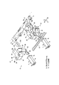
なお、特に、図1は本実施例の車両のフロントサブフレームを前方左斜め上方から見た斜視図を示し、図7はブレース及び該ブレースを取り外した状態のフロントサブフレームを下方から見た分解斜視図を示している。
An embodiment of the present invention will be described in detail with reference to the drawings.
FIGS. 1-7 has shown the front sub-frame structure of the motor vehicle of a present Example.
In particular, FIG. 1 is a perspective view of the front subframe of the vehicle according to the present embodiment as seen from the diagonally upper left side, and FIG. 7 is an exploded view of the brace and the front subframe from which the brace is removed seen from below. A perspective view is shown.
また本実施例の図面において、図2以外は、ステアリングラック55、パワステ用モータ56、及びパワステ用ピニオン57の図示を省略し、図4はテンションロッド51、及びロアアーム52の図示を省略し、図5及び図6はバンパレインフォースメント7aの図示を省略し、図7及び後述する図8はこれらバンパレインフォースメント7a、テンションロッド51、ロアアーム52に加えて、スタビライザ支持部62及びスタビライザ100の図示を省略するものとする。さらに、以下の実施例においては、図中、矢印Fは車両前方を示し、矢印LEは車幅方向の左方を示し、矢印RIは車幅方向の右方を示し、矢印Uは車両上方を示す。
In the drawings of this embodiment, the illustration of the
自動車の前部には、図4に示すように、車室の前面部に設置されたダッシュパネル1と、該ダッシュパネル1の下部から車両の前方側に延びる左右一対のフロントサイドフレーム2,2(左側のみ図示)とを有し、該フロントサイドフレーム2の下方には、図1〜図6に示すように、ストラット式フロントサスペンション装置用として車幅方向外側へ略水平に延びるロアアーム52(ラテラルロッド)(図1、図2参照)と該ロアアーム52より前方から車幅方向外側後方へ延びるテンションロッド51(同図参照)等を支持するフロントサブフレーム5が配設されている。
As shown in FIG. 4, a dash panel 1 installed on the front part of the passenger compartment and a pair of left and right
本実施例のフロントサイドフレーム2は、側面視で車両の前後方向に沿って略水平に延びる水平部2aと、その後端部から上記ダッシュパネル1の下端部に沿って後下がりに傾斜して延びるキックアップ部2b(傾斜部)とを有し、該キックアップ部2bの後端部には、車両の後方側に延びるフロアフレーム3が連設されている(図4参照)。また、上記フロントサイドフレーム2の前端部には、車両の前方側に向けて突出する金属製の筒状体等からなるクラッシュカン4が設けられるとともに、その前端面には、車幅方向に延びるバンパレインフォースメント4aが取り付けられている。
The
上記フロントサブフレーム5は、図1〜図7に示すように、主に、車両の前後方向に延びる左右一対のサイドメンバ6,6と、サイドメンバ6の前方に延びるサブクラッシュカン7と、サイドメンバ6とサブクラッシュカン7とを前後方向に連結してフロントサブフレーム5の前側を構成するサブフレーム前側構造体10(連結部材)と、左右一対のサブフレーム前側構造体10、10同士を連結するように車幅方向に延びるサスペンションクロスメンバ73(以下、「サスクロスメンバ73」という。)と、左右一対のサイドメンバ6,6同士を連結するように車幅方向に延びるリヤクロスメンバ74と、一対のサイドメンバ6,6間におけるリヤクロスメンバ74よりも後方においてこれらメンバ6,6,74に接合された傾斜メンバ75とブレース80とを備えている。
1 to 7, the
また、図1、図2及び図4に示すように、フロントサブフレーム5は、サブフレーム前側構造体10の前部、サイドメンバ6の前後方向の間部分、及びサイドメンバ6の後端の3点において、夫々上方に突出したマウント部M1,M2,M3(マウントブッシュやマウントパイプ34)が接合されており、それぞれ前方から後方へ第1マウント部M1(前側車体取付部)、第2マウント部M2、第3マウント部M3(後側車体取付部)と設定する。
As shown in FIGS. 1, 2, and 4, the
図4に示すように、第1マウント部M1は、車体側のフロントサイドフレーム2の水平部2aの前端に連結され、第2マウント部M2は、該水平部2aの後部において連結され、第3マウント部M3は、フロアフレーム3の前端(キックアップ部2bとの連設部分)に連結されている。
これにより、フロントサブフレーム5は、前後方向の片側3点、左右両側で計6点にて車体にマウントされ、車体の下側に配設されている。
As shown in FIG. 4, the first mount part M1 is connected to the front end of the
Thus, the
サブクラッシュカン7は、上記フロントサイドフレーム2の前端のクラッシュカン4と同様に衝撃エネルギ吸収部材であり、図2〜図4に示すように、サブクラッシュカン7の前端部には、左右各側の前端部を連結するように車幅方向に延びるサブバンパレインフォースメント7aを備えている。
The sub-crash can 7 is an impact energy absorbing member similar to the crash can 4 at the front end of the
サイドメンバ6は、図4に示すように、左右一対のフロントサイドフレーム2、及びフロアフレーム3の下方に架設され、図1〜図4及び図7に示すように、丸パイプ状に前後方向に延びている。サイドメンバ6は、該サイドメンバ6の前後方向の第2マウント部M2より前側に有するサイドメンバ前方部6aと、該第2マウント部M2よりも後側に有するサイドメンバ後方部6bとを備えている(図示省略)。
As shown in FIG. 4, the
サイドメンバ前方部6a、及びサイドメンバ後方部6bは、いずれも側面視で後下がり傾斜状に延びているが(図4参照)、サイドメンバ前方部6aは、前端から第2マウント部M2へ向けて平面視で車幅方向の外側へ傾斜状に延びているとともに(図2、3参照)、サイドメンバ後方部6bは、平面視で左右各側が互いに平行になるように前後方向に延びている(同図参照)。このサイドメンバ後方部6bの後端下部には、ボルト及びナットN、或いはファスナ等の取付部材(図示省略)によりブレース80を取り付ける取付け孔等からなるサイドメンバ側連結部92aを形成している(図7参照)。
The side
サブフレーム前側構造体10は、図1〜図5及び図7に示すように、サブクラッシュカン7とサイドメンバ6との間に介在し、前方から後方へ順にサブクラッシュカン7の後端フランジ7bを取り付けるセットプレートとしてのサブクラッシュカン取付部12と、前側車体取付部13と、テンションロッド支持部14と、閉断面状連結部15とを備えている。
As shown in FIGS. 1 to 5 and 7, the
換言すると、サブフレーム前側構造体10は、図8及び図9(a)、(b)に示すように、複数枚のパネル部材を立体形状に組み立てて構成し、サブフレーム前側構造体本体20とテンションロッド支持ブラケット40と閉断面構成パネル151とを備えている。
In other words, the
なお、図8はフロントサブフレームの前側の特にサブフレーム前側構造体の分解斜視図であり、図8中の符号59はラジエータ支持ブラケットある。また、図9(a)は左側のサブフレーム前側構造体を左斜め45度後方から見た斜視図であり、図9(b)はサブフレーム前側構造体の底面図である。
FIG. 8 is an exploded perspective view of the front side sub-frame, in particular, the front sub-frame structure, and
サブフレーム前側構造体本体20は、サブフレーム前側構造体10の前後方向の長さを有する上面部21と、該上面部21の後端から下方に突片状に折り曲げて延びる後面部22と、サブフレーム前側構造体10の前面に相当し、サブクラッシュカン7の後端フランジ7bとを取り付けるサブクラッシュカン取付部12と、底面部23とで形成している(同図参照)。
The subframe
後面部22は、図9(a)に示すように、閉断面状連結部15の後面に相当し、サイドメンバ6の前部を挿通する円形状の開口部22aが形成され、該開口部22aにサイドメンバ6の前端を挿通した状態で接合固定するサイドメンバ接合面として形成している。
As shown in FIG. 9A, the
サブクラッシュカン取付部12は、図4、図5及び図8に示すように、サブフレーム前側構造体10の前面に相当し、サブクラッシュカン7の後端に備えた後端ブラケット7bよりも一回り大きな正面視略四角形状のセットプレートとして形成している。
なお、サブクラッシュカン7は、その後端に備えた後端ブラケット7bをサブクラッシュカン取付部12に対面させるとともに、図4及び図5に示すように、ボルトB及びナット(図示省略)等により締結固定され、サブフレーム前側構造体10に連結されている。
As shown in FIGS. 4, 5 and 8, the sub-crash can mounting
The sub-crash can 7 has a
さらに、図4、図7、図8及び図9(a)に示すように、サブフレーム前側構造体本体20は、後述する前側車体取付部13に相当する部位における上面部21の下方に、サブクラッシュカン荷重伝達部材30を備えている。サブクラッシュカン荷重伝達部材30は、外側面31、内側面32(図7参照)、及び隔壁33とで前後方向の直交断面が下方に向けて開口する門型(コの字形状)に形成され、サブクラッシュカン取付部12の後面とテンションロッド支持部14の前壁面41との間に架設される(図4、図7、図9(a)参照)。
Further, as shown in FIGS. 4, 7, 8, and 9 (a), the sub-frame
サブクラッシュカン荷重伝達部材30の外側面31には、図1、図4、図7〜図9(a)に示すように、前後方向に長軸を有する楕円形状のサービスホール31a(作業用貫通孔)が形成されている。
As shown in FIGS. 1, 4, and 7 to 9 (a), the
隔壁33は、サブクラッシュカン荷重伝達部材30の上面に相当し、車幅方向において互いに支持する外側面31と内側面32との上端を車幅方向に連結するように形成され、サブフレーム前側構造体10の上面部21の下方で該上面部21と対向するとともに前側車体取付部13の内部空間を上下各側に隔離するように配設されている。すなわち、前側車体取付部13は、底面を有さずに下方が開口して形成するとともに、上面部21と隔壁33とで二階建て構造としている。
The
また、図1〜図5、図9(a)に示すように、サブフレーム前側構造体10における前側車体取付部13(いわゆる「ツノ部材」)には、上面部21及び隔壁33の平面視中央部において上下方向に連通するとともに上面部21から上方へタワー型に延出するように立設するマウントパイプ34を備え、第1マウント部M1を構成している。
Further, as shown in FIGS. 1 to 5 and FIG. 9A, the front vehicle body attachment portion 13 (so-called “horn member”) in the
さらにまた、テンションロッド支持ブラケット40は、図8に示すように、車幅方向外側後方に沿って配設された前壁面41及び後壁面42と、これらの車幅方向内側前端同士を車幅方向内側後方へ結ぶ車幅方向内側壁面43とで車幅方向外側後方に向けて開口する平面視コ字状に形成し、サブフレーム前側構造体本体20の上面部21と底面部23との間に介在している(図1、図4、図7、図9(a)、(b)参照)。
Furthermore, as shown in FIG. 8, the tension
このテンションロッド支持ブラケット40の前壁面41と後壁面42とには、図8及び図9(a)に示すように、互いに対向するようにテンションロッド支持孔41aが形成され、これら一対のテンションロッド支持孔41a,41a間に架設されたボルトBと、該ボルトBを締結するナット(図示省略)とでテンションロッド51の基端部を枢支するテンションロッド支持軸44を構成し、該テンションロッド支持軸44を備えたテンションロッド支持ブラケット40は、前記テンションロッド支持部14として形成している(図3、図9(a)参照)。
さらに、図1〜図3及び図7に示すように、テンションロッド支持部14における車幅方向内側壁面43には、上述したサスクロスメンバ73は、その車幅方向両端部が車幅方向内面から接合されている。
As shown in FIGS. 8 and 9A, tension
Further, as shown in FIGS. 1 to 3 and 7, the
また、図8に示すように、閉断面構成パネル151は、前後方向の直交断面が上方に向けて開口するハット状に形成し、図7及び図9(a)、(b)に示すように、サブフレーム前側構造体本体20の上面部21の後部において下面から接合することで前後方向に延びる閉断面を有する閉断面状連結部15を構成している。
Further, as shown in FIG. 8, the closed
さらにまた、図3、図4図7及び図9(a)に示すように、テンションロッド支持部14後方かつ閉断面状連結部15の下方には、ステアリングラック55等配設用に下方に開口した凹部Aが構成される。
Furthermore, as shown in FIG. 3, FIG. 7, FIG. 7 and FIG. 9A, an opening is provided below the tension
ところで、図1〜図6に示すように、テンションロッド支持部14の車幅方向内側壁面43及びサスクロスメンバ73に沿って車幅方向に延びるスタビライザ100が配設されている。
By the way, as shown in FIGS. 1-6, the
詳しくは、スタビライザ100は、サスクロスメンバ73の後方近傍において車幅方向に略水平に延び、その車幅方向の両側は、平面視すると閉断面状連結部15をその下側から車幅方向に跨ぐように後方程車幅方向外側に傾斜状に延びているが、閉断面状連結部15を下側から跨ぐ部分は、閉断面状連結部15の下方に有する凹部Aを横切って通過するように車幅方向に水平に延びている(図3、図4参照)。
なお、スタビライザ100は、周知のとおり、ねじり剛性の抵抗により片輪のみのバンプ、リバウンド時にロール角を抑制するものである。
Specifically, the
In addition, the
上述したスタビライザ100は、図1、図3、図4に示すように、該スタビライザ100を保持するスタビライザ取付けブラケット60に保持された状態で、締結手段としてのボルトB及びナット(図示省略)により、閉断面状連結部15の下面に締結固定されている。このように、スタビライザ100を保持した状態のスタビライザ取付けブラケット60によりスタビライザ支持部62が構成され、該スタビライザ支持部62がこの凹部Aに配置されている。
As shown in FIGS. 1, 3, and 4, the above-described
また、図1、図3、図4、図7及び図8に示すように、リヤクロスメンバ74の車幅方向両端部のサイドメンバ6,6との接合部には、前輪の車幅方向の位置を決定すべく車幅方向外側へ延びるロアアーム52を上下方向に枢支可能に該ロアアーム52の基端部を支持するアーム支持部71が設けられている。すなわち、左右のサイドメンバ6,6は、リヤクロスメンバ74を介してロアアーム52を支持している。
In addition, as shown in FIGS. 1, 3, 4, 7, and 8, the joints of the
さらにまた、図1〜図4、図6及び図7に示すように、傾斜メンバ75は、フロントサブフレーム5の後方の左右各側に一対備え、平面視ハの字形状に配置されている。詳しくは、傾斜メンバ75は、リヤクロスメンバ74の車幅方向の中間部に対して左右に離間した左右中間部にその前端が接合され、該左右中間部と、該左右のサイドメンバ6の後端車体取付部としての第3マウント部M3とを夫々連結するように後方程車幅方向外側へ直線状に傾斜して後方へ末広がり状に延びている(図2、図3、図7参照)。この傾斜メンバ75の前方下部には、ボルト及びナット、或いはファスナ等の取付部材(図示省略)によりブレース80を取り付ける取付け孔等からなる傾斜メンバ側連結部91aを形成している(図7参照)。
Furthermore, as shown in FIGS. 1 to 4, 6, and 7, a pair of
また、図1〜図6に示すように、ブレース80は、上下方向に略直交する面を構成するように配設された後述する複数のブレースメンバ81,82,83から成り、左右一対のサイドメンバ後方部6b,6bとその前端で車幅方向に延びるリヤクロスメンバ74とで平面視後方が開口するコ字状に構成される空間を跨ぐようにこれらメンバ6b,6b,74の下側から配されている。
1 to 6, the
具体的には、図1〜図3及び図7に示すように、ブレース80は、X字状メンバ体81(X字状ビーム)と左右一対の前後方向延設メンバ82,82(前後方向ビーム)と後端車幅方向延設メンバ83(車幅方向ビーム)とで一体に構成している。
Specifically, as shown in FIGS. 1 to 3 and 7, the
X字状メンバ体81は、左側のアーム支持部71と、これに対して平面視対角線上に位置する右側のサイドメンバ6の第3マウント部M3(後側車体取付け部)とを直線状に連結する一方の対角線延設メンバ81aに備えるとともに、右側のアーム支持部71と、これに対して平面視対角線上の左側に位置するサイドメンバ6の第3マウント部M3(後側車体取付け部)とを直線状に連結する他方の対角線延設メンバ81aとを備え、これら一対の対角線延設メンバ81a,81aを中央でクロスさせた平面視X字形状に構成している(図3、図7参照)。
The
前後方向延設メンバ82,82は、ブレース80の左右両端において前後方向に延びている。すなわち、前後方向延設メンバ82,82は、左右各側において夫々に対応するアーム支持部71の基端部71a(アーム支持部71の車幅方向内側端部)(図3及び図7参照)とサイドメンバ6の後側車体取付け部(第3マウント部M3)とを直線状に連結するように左右一対を備えている。
The
このように、アーム支持部71の基端部71aは、リヤクロスメンバ74の車幅方向においてサイドメンバ6との接合部に対して車幅方向内側にずらした位置に有している。このアーム支持部71の基端部71aには、ボルト及びナットN、或いはファスナ等の取付部材(図示省略)によりブレース80を取り付ける取付け孔等からなるリヤクロスメンバ側連結部90aを形成している(図7参照)。
Thus, the base end portion 71 a of the
また、ブレース80は、左右一対の前後方向延設メンバ82,82は、後方サイドメンバ6が延びる前後方向に対して前方程車幅方向内側へ傾斜するように配置されている(図3参照)。
In addition, the
図1〜図3及び図7に示すように、後端車幅方向延設メンバ83は、ブレース80の後端において車幅方向に延びている。すなわち、後端車幅方向延設メンバ83は、左右のサイドメンバ6,6の第3マウント部M3を直線状に連結するように延びている。
As shown in FIGS. 1 to 3 and 7, the rear end vehicle width
これらX字状メンバ体81と左右一対の前後方向延設メンバ82,82と後端車幅方向延設メンバ83は、互いに一体に接合してブレース面を構成しているため、該ブレース面を構成する面内には、平面視三角形状(トラス形状)のメンバの集合体を構成することができる(同図参照)。
The
ブレース80の左右各側の前後方向延設メンバ82の前端(X字状メンバ体81の前端)には、リヤクロスメンバ7に連結可能にボルト及びナットN、或いはファスナ等の取付部材(図示省略)を取り付ける取付け孔等からなるブレース前側連結部90bが形成されている(図7参照)。
At the front end (front end of the X-shaped member body 81) of the
ブレース80の左右各側の対角線延設メンバ81aの前部には、傾斜メンバ75の前部に連結に連結可能にボルト及びナットN、或いはファスナ等の取付部材(図示省略)を取り付ける取付け孔等からなるブレース中間連結部91bが形成されている(同図参照)。
Mounting holes or the like for attaching mounting members (not shown) such as bolts and nuts N or fasteners to the front part of the diagonally extending
ブレース80の左右各側の前後方向延設メンバ82の後端(換言するとX字状メンバ体81の後端)には、サイドメンバ6に連結可能にボルト及びナットN、或いはファスナ等の取付部材(図示省略)を取り付ける取付け孔等からなるブレース後側連結部92bが形成されている(同図参照)。
Mounting members such as bolts and nuts N or fasteners are connectable to the
なお、本実施例のブレース80は、例えば、その前端において車幅方向に延びる前端車幅方向延設メンバを備えていないが、適宜メンバを付加した構成であってもよい。
The
上述したブレース80は、図1〜4及び図6に示すように、サブフレーム5の本体側後部、すなわちサイドメンバ6、リヤクロスメンバ74、及び傾斜メンバ75の下側に配置され、これらメンバ74,75,6の夫々に前側連結部90と中間連結部91と後側連結部92によって左右各側から取り付けられている。
1-4 and FIG. 6, the
前側連結部90は、図3及び図7に示すように、リヤクロスメンバ側連結部90aとブレース前側連結部90bと取付部材(図3中にナットNのみ図示)とで構成し、リヤクロスメンバ側連結部90aとブレース前側連結部90bとは取付部材を介して互いに連結されている。
As shown in FIGS. 3 and 7, the front
中間連結部91は、傾斜メンバ側連結部91aとブレース中間連結部91bと取付部材(図3中にナットNのみ図示)とで構成し、傾斜メンバ側連結部91aとブレース中間連結部91bとは取付部材を介して互いに連結されている(同図参照)。
The intermediate connecting
後側連結部92は、サイドメンバ側連結部92aとブレース後側連結部92bと取付部材(図3中にナットNのみ図示)とで構成し、サイドメンバ側連結部92aとブレース後側連結部92bとは取付部材を介して互いに連結されている(同図参照)。
The rear
また、本実施例のフロントサブフレーム5は、左右のサイドメンバ後方部6b,6bとリヤクロスメンバ74とで平面視後方へ開口するコ字状に構成され、この平面視後方を向けて開口するコ字状の内側空間の上方には、前後方向にクランクシャフトが並んだ縦置きタイプのエンジン(図示省略)が配置される。よって、左右の後側サイドメンバ6b,6bとリヤクロスメンバ74との間の隅角部には、図1〜図7に示すように、この縦置きタイプのエンジンを搭載するエンジンマウントブラケット72を備えている。
Further, the
エンジンマウントブラケット72は、リヤクロスメンバ74と傾斜メンバ75とサイドメンバ6の夫々に溶接により一体に接合されている。すなわち、これらメンバ6,74,75は、エンジンマウントブラケット72を介して互いに連結されている。
The
上述したとおり、本実施例のフロントサブフレーム構造は、フロントサブフレーム5の左右サイドメンバ6,6に支持されたアーム支持部71,71を連結するリヤクロスメンバ74が設けられ(図1〜図8参照)、該リヤクロスメンバ74の左右に離間した左右中間部とサイドメンバ6,6の後部の第3マウント部M3(後側車体取付部)とを各々連結する傾斜メンバ75が設けられ(図1〜図4、図6、図7参照)、左右のアーム支持部71,71と対角線上の第3マウント部M3とを連結するブレース80が設けられ、該ブレース80と傾斜メンバ75の中間部を連結する中間連結部91が設けられたものである(図3参照)。
As described above, the front subframe structure of the present embodiment is provided with the
上記構成によれば、フロントサブフレーム5の後部の左右各側においてリヤクロスメンバ74の左右に離間した左右中間部からサイドメンバ6,6後部の第3マウント部M3に向けて後方程車幅方向外側に傾斜するように延びる傾斜メンバ75を、ブレース80に連結した中間連結部91を設けることでブレース80が薄くても上下方向に撓まないようにすることができ、ブレース80としての機能を効果的に発揮することができる。
According to the above-described configuration, the vehicle width direction in the rearward direction from the left and right intermediate portions of the
詳述すると、フロントサブフレーム5の前部の下方には、サイドメンバ6とロアアーム52(ラテラルリンク)とテンションロッド51とを平面視三角形状となるように配設している。一方、車両の重心を下げるためにエンジンをできるだけ低く配置したいという要求があるため、本実施例において、エンジンは、前後方向にクランクシャフトが並んだ縦置きタイプのエンジン(図示省略)とするとともに、上述したロアアーム52やテンションロッド51等が配置されていないフロントサブフレーム5の後部に配設している。
Specifically, the
ところが、フロントサブフレーム5の後部は、左右のアーム支持部71に連結されたリヤクロスメンバ74と、左右各側において後方に延びるサイドメンバ後方部6b,6bとで構成された平面視台形形状のフレーム構造となるが、このような剛性が低い後部にエンジンを搭載した場合、走行時の支持剛性を確保することが困難になるおそれがあった。
However, the rear portion of the
特に、上述した縦置きタイプのエンジンを搭載した場合は、アクセル踏み込み時にエンジンの駆動に伴ってタイヤが回転する際の反力を受けてエンジンの支持剛性を確保することが困難になるおそれもあった。 In particular, when the above-mentioned vertical engine is mounted, it may be difficult to secure the support rigidity of the engine due to the reaction force when the tire rotates as the engine is driven when the accelerator is depressed. It was.
このような場合においてエンジンの支持剛性が低いと走行時のハンドル操作の応答性に悪影響を及ぼすため、走行時、特に旋回時の車体の剛性を高める必要があり、フロントサブフレーム5の後部にエンジンを配置した構成においても、エンジンの支持剛性を確保できることが課題があった。
In such a case, if the support rigidity of the engine is low, the responsiveness of the steering wheel operation during driving will be adversely affected. Therefore, it is necessary to increase the rigidity of the vehicle body during driving, particularly during turning, and the engine is located at the rear of the
このような課題に対して、本実施例においては、フロントサブフレーム5の後部において、リヤクロスメンバ74の左右に離間した左右中間部とサイドメンバ後方部6b,6bの第3マウント部M3とを各々連結する傾斜メンバ75が設けられ、該傾斜メンバ75とブレース80とを中間連結部91において連結したため、該フロントサブフレーム5の後部にエンジンを搭載しても、エンジン支持剛性を確保することができる。
In order to deal with such a problem, in the present embodiment, at the rear portion of the
詳述すると、フロントサブフレーム5の後部を仮に、傾斜メンバ75を備えずにブレース80単体で補強した場合、ブレース80はそれ自体薄いため、上下動して荷重をしっかりと受け止めることができないおそれがある。ところが、本実施例のように、剛性の高い傾斜メンバ75を備えるとともに、中間連結部91によって互いに連結したため、互いの一体性が増して傾斜メンバ75によってブレース80を補強できるとともに、傾斜メンバ75と、ブレース80を構成する複数のメンバ81(81a,81a),82,83によってフロントサブフレーム5の後部に平面視複数のトラス構造を構成できる。よって、傾斜メンバ75により、左右サイドメンバ6,6と、車幅方向に延びるリヤクロスメンバ74とで構成される平面視略台形形状が例えば、平行四辺形等の菱形形状に平面内で崩れる方向の変形を規制するとともに、ブレース80の上下方向の変形を抑制してブレース80としての機能を高めることができる。
More specifically, if the rear portion of the
つまり、傾斜メンバ75とブレース80との相乗的な作用によってフロントサブフレーム5の後部のエンジン支持剛性を向上させることができる。
In other words, the synergistic action of the
さらに、このブレース80は、図示省略するがアンダカバーの上面にファスナ等を用いて装着することで該アンダカバーの補強部材としても機能させることができる。なお、アンダカバーは、空力特性改善のため、或いは走行時のサスペンションを水や泥、飛石等から保護するために、車両床下においてフロントサブフレーム5を覆うために備えるカバーである。
Furthermore, although not shown, the
このように、アンダカバーの強度部材としてブレース80を配設することでアンダカバーを補強しつつ、パネル状のアンダカバー自体を薄肉化して車両重量の軽量化を図ることができる。
Thus, by arranging the
また、この発明の態様として、リヤクロスメンバ74と傾斜メンバ75とサイドメンバ6がエンジンマウントブラケット72で溶接により一体に連結されたものである(図1、図2、図6参照)。
Further, as an aspect of the present invention, the
上記構成によれば、左右各側においてエンジンマウントブラケット72を、リヤクロスメンバ74と傾斜メンバ75とサイドメンバ6に連結したため、左右各側に備えたエンジンマウントブラケット72によるエンジンの支持剛性を向上できる。これにより、車幅方向中央に別途、エンジン支持構造を設ける必要がなく、エンジンを低い位置で配置して車両重心を下げることが可能となり、ロールやトラクションを改善できる。さらに、リヤクロスメンバ74と傾斜メンバ75とサイドメンバ6の一体性が向上するため、エンジン支持剛性だけでなく、サスペンションの支持剛性も向上させることができる。
According to the above configuration, since the
また、この発明の態様として、ブレース80は、その左右と後にブレースメンバ82,82,83を備えたものである(図1〜図3、図7参照)。
In addition, as an aspect of the present invention, the
上記構成によれば、互いにクロスするX字状メンバ体81と、左右の前後方向延設メンバ82,82と後端車幅方向延設メンバ83とで、ブレース80自体が複数のトラス形状から成る構造となるのでトラス構造を増やしてより高剛性化することができる。
According to the above configuration, the
また、この発明の態様として、本実施例のブレース80は、左右各側に前後方向延設メンバ82,82を備え、これら前後方向延設メンバ82,82は、その後端が第3マウント部M3を備えたサイドメンバ6後部に接合されている。すなわち、後側連結部92においてサイドメンバ側連結部92aとブレース後側連結部92bとは取付部材を介して互いに連結されている。さらに、前後方向延設メンバ82,82は、前方程車幅方向内側に傾斜するように前方に延び、その前端がアーム支持部71の基端部71aに接合されている(図3参照)。すなわち、前側連結部90においてリヤクロスメンバ側連結部90aとブレース前側連結部90bとが取付部材を介して互いに連結されている。
As an aspect of the present invention, the
すなわち、前後方向延設メンバ82,82は、その前部がサイドメンバ6に対して車幅方向内側にずらすように傾けて配置している。これにより、ブレース80は、左右各側において、該前後方向延設メンバ82とサイドメンバ6とリヤクロスメンバ74とによってもトラス構造を構成することができるとともに、該前後方向延設メンバ82と傾斜メンバ75と対角線延設メンバ81aとによってもトラス構造を構成することができ、より高剛性化することができる。
That is, the
この発明の構成と、上述の実施例との対応において、サブフレームは、フロントサブフレーム5に対応し、以下、同様に、
クロスメンバは、サスクロスメンバ73に対応し、
左右に備えたブレースメンバは、前後方向延設メンバ82に対応し、
後に備えたブレースメンバは、後端車幅方向延設メンバ83に対応し、
一方側車体取付部は、第3マウント部M3(後側車体取付部)に対応し、
サイドメンバの前後方向の一方側は、サイドメンバ6の後部に対応し、
一方側の端部は、後に対応するも、この発明は、上述の実施例の構成のみに限定されるものではない。
In the correspondence between the configuration of the present invention and the above-described embodiment, the subframe corresponds to the
The cross member corresponds to the
The brace members provided on the left and right correspond to the
The rear brace member corresponds to the rear end vehicle width
The one side vehicle body attachment portion corresponds to the third mount portion M3 (rear side vehicle body attachment portion),
One side of the side member in the front-rear direction corresponds to the rear part of the
Although the end on one side will correspond later, the present invention is not limited to the configuration of the above-described embodiment.
例えば、上述した中間連結部91(91a、91b)は、互いに固定してもよく、または少なくとも一方を長孔とし、ブレース80の面方向にスライド可能に連結しても良い。このように中間連結部91をスライド可能に連結した場合、トラス構造の増加による剛性向上効果は低下するものの、中間連結部91への過度の応力集中を防ぎ、中間連結部91の簡素化や軽量化を図りつつ、ブレース80の上下方向の撓みを防ぎ、単に傾斜メンバ75とブレース80を併用する構成に対し、効果的に高剛性化することができる。
For example, the intermediate connecting portions 91 (91a, 91b) described above may be fixed to each other, or at least one of them may be a long hole and connected so as to be slidable in the surface direction of the
以上説明したように、本発明は、サブフレームの左右サイドメンバに支持されたアーム支持部を連結するクロスメンバが設けられ、該クロスメンバの左右に離間した左右中間部とサイドメンバの前後方向の一方側の一方側車体取付部とを各々連結する傾斜メンバが設けられたフロントサブフレーム構造について有用である。 As described above, according to the present invention, the cross member that connects the arm support portions supported by the left and right side members of the subframe is provided. This is useful for the front sub-frame structure provided with the inclined members that respectively connect the one-side vehicle body mounting portions on one side.
5…フロントサブフレーム(サブフレーム)
6…サイドメンバ
71…アーム支持部
72…エンジンマウントブラケット
74…リヤクロスメンバ(クロスメンバ)
75…傾斜メンバ
80…ブレース
82…前後方向延設メンバ(左右に備えたブレースメンバ)
83…後端車幅方向延設メンバ(後に備えたブレースメンバ)
91…中間連結部
M3…第3マウント部(一方側車体取付部)
5. Front subframe (subframe)
6 ...
75 ...
83 ... Rear end vehicle width direction extending member (brace member provided later)
91 ... Intermediate connection part M3 ... 3rd mount part (one side vehicle body attachment part)
Claims (3)
該フロントサブフレームの左右サイドメンバに支持されたアーム支持部を連結するクロスメンバが設けられ、該クロスメンバの左右に離間した左右中間部と前記サイドメンバの前後方向の一方側の一方側車体取付部とを各々連結する傾斜メンバが設けられ、左右の前記アーム支持部と対角線上の前記一方側車体取付部とを連結するブレースが設けられ、該ブレースと前記傾斜メンバの中間部を連結する中間連結部が設けられた
フロントサブフレーム構造。 A front subframe structure of an automobile in which a pair of left and right front side frames extending from the front portion of the passenger compartment to the front side of the vehicle is provided, and a front subframe for supporting the front suspension device is provided below the front side frame. ,
A cross member for connecting arm support portions supported by the left and right side members of the front subframe is provided, and a left and right middle portion of the cross member that is separated to the left and right and one side body attachment on one side of the side member in the front-rear direction Inclined members are provided for connecting the respective parts, braces are provided for connecting the left and right arm support parts and the one-side vehicle body mounting part on the diagonal line, and an intermediate part for connecting the braces and the intermediate part of the inclined members is provided. Front subframe structure with connecting part.
請求項1に記載のフロントサブフレーム構造。 The front sub-frame structure according to claim 1, wherein the cross member, the inclined member, and the side member are connected by an engine mount bracket.
請求項1、又は2に記載のフロントサブフレーム構造。 The front sub-frame structure according to claim 1, wherein the brace includes brace members at left and right sides and at one end of the brace.
Priority Applications (5)
| Application Number | Priority Date | Filing Date | Title |
|---|---|---|---|
| JP2015221131A JP6237748B2 (en) | 2015-11-11 | 2015-11-11 | Front subframe structure |
| PCT/JP2016/082477 WO2017082125A1 (en) | 2015-11-11 | 2016-11-01 | Front sub-frame structure |
| CN201680064343.1A CN108349539B (en) | 2015-11-11 | 2016-11-01 | Front auxiliary frame structure |
| US15/761,176 US10118643B2 (en) | 2015-11-11 | 2016-11-01 | Front sub-frame structure |
| DE112016005166.2T DE112016005166T5 (en) | 2015-11-11 | 2016-11-01 | Front subframe structure |
Applications Claiming Priority (1)
| Application Number | Priority Date | Filing Date | Title |
|---|---|---|---|
| JP2015221131A JP6237748B2 (en) | 2015-11-11 | 2015-11-11 | Front subframe structure |
Publications (2)
| Publication Number | Publication Date |
|---|---|
| JP2017087990A JP2017087990A (en) | 2017-05-25 |
| JP6237748B2 true JP6237748B2 (en) | 2017-11-29 |
Family
ID=58695150
Family Applications (1)
| Application Number | Title | Priority Date | Filing Date |
|---|---|---|---|
| JP2015221131A Active JP6237748B2 (en) | 2015-11-11 | 2015-11-11 | Front subframe structure |
Country Status (5)
| Country | Link |
|---|---|
| US (1) | US10118643B2 (en) |
| JP (1) | JP6237748B2 (en) |
| CN (1) | CN108349539B (en) |
| DE (1) | DE112016005166T5 (en) |
| WO (1) | WO2017082125A1 (en) |
Families Citing this family (26)
| Publication number | Priority date | Publication date | Assignee | Title |
|---|---|---|---|---|
| DE102015004465B4 (en) * | 2015-04-04 | 2018-09-06 | Audi Ag | Two-lane vehicle |
| JP6237747B2 (en) * | 2015-11-11 | 2017-11-29 | マツダ株式会社 | Front subframe structure |
| CN107351917B (en) * | 2017-07-21 | 2023-08-18 | 马瑞利汽车底盘系统(广州)有限公司 | Front auxiliary frame structure |
| DE102017218276A1 (en) * | 2017-10-12 | 2019-04-18 | Bayerische Motoren Werke Aktiengesellschaft | Axle carrier of a vehicle with a bearing part for a stabilizer bar |
| JP6624182B2 (en) * | 2017-11-16 | 2019-12-25 | スズキ株式会社 | Body structure |
| JP6950561B2 (en) * | 2018-02-15 | 2021-10-13 | トヨタ自動車株式会社 | Body structure |
| US11198473B2 (en) * | 2018-02-20 | 2021-12-14 | Mazda Motor Corporation | Subframe structure |
| JP7035825B2 (en) * | 2018-06-06 | 2022-03-15 | マツダ株式会社 | Subframe structure |
| JP6973328B2 (en) * | 2018-08-22 | 2021-11-24 | マツダ株式会社 | Vehicle front body structure |
| JP6772230B2 (en) * | 2018-09-27 | 2020-10-21 | 本田技研工業株式会社 | Body front structure |
| US20240300580A1 (en) * | 2018-09-27 | 2024-09-12 | Honda Motor Co., Ltd. | Front subframe structure |
| JP7025315B2 (en) * | 2018-09-27 | 2022-02-24 | 本田技研工業株式会社 | Body front structure |
| JP6761012B2 (en) * | 2018-09-27 | 2020-09-23 | 本田技研工業株式会社 | Front subframe structure |
| DE102018009196B3 (en) * | 2018-11-22 | 2019-11-21 | Daimler Ag | Front structural arrangement for a motor vehicle body shell |
| JP7274142B2 (en) * | 2019-03-29 | 2023-05-16 | 株式会社エフテック | vehicle subframe |
| KR102660369B1 (en) * | 2019-04-11 | 2024-04-23 | 현대자동차주식회사 | Front body of vehicle |
| JP7400238B2 (en) * | 2019-07-24 | 2023-12-19 | マツダ株式会社 | subframe structure |
| JP7298361B2 (en) * | 2019-07-24 | 2023-06-27 | マツダ株式会社 | front suspension device |
| JP7260500B2 (en) | 2020-03-19 | 2023-04-18 | トヨタ自動車株式会社 | vehicle |
| US11247726B2 (en) * | 2020-03-25 | 2022-02-15 | Volvo Car Corporation | Subframe assembly for a vehicle |
| US11299210B2 (en) * | 2020-05-29 | 2022-04-12 | GM Global Technology Operations LLC | Structural integration brace for front vehicle compartment |
| FR3118025B3 (en) | 2020-12-17 | 2022-12-09 | Arc France | Method of manufacturing a hollow glass article |
| CN112706668B (en) * | 2021-01-08 | 2022-06-21 | 上汽大众汽车有限公司 | Automobile seat |
| JP7397020B2 (en) * | 2021-03-15 | 2023-12-12 | トヨタ自動車株式会社 | vehicle |
| EP4299420A1 (en) * | 2022-07-01 | 2024-01-03 | Autotech Engineering S.L. | Auxiliary frame for a vehicle, in particular an electric vehicle |
| US12084111B2 (en) * | 2022-09-12 | 2024-09-10 | Ferrari S.P.A. | Motor vehicle provided with a reinforcing structure |
Family Cites Families (16)
| Publication number | Priority date | Publication date | Assignee | Title |
|---|---|---|---|---|
| DE19730404B4 (en) * | 1997-07-16 | 2005-04-21 | Daimlerchrysler Ag | Subframe for motor vehicles |
| JP4195325B2 (en) * | 2003-04-23 | 2008-12-10 | 三菱アルミニウム株式会社 | Body frame structure |
| DE102006013548C5 (en) * | 2006-03-24 | 2018-01-18 | Audi Ag | As a subframe trained subframe for motor vehicles and vehicle body |
| JP4697005B2 (en) * | 2006-03-29 | 2011-06-08 | 三菱自動車工業株式会社 | Body structure |
| DE102007035510A1 (en) | 2007-07-28 | 2009-01-29 | Bayerische Motoren Werke Aktiengesellschaft | Subframe in the chassis area of a two-lane vehicle |
| WO2009072614A1 (en) * | 2007-12-07 | 2009-06-11 | Toyota Jidosha Kabushiki Kaisha | Car body substructure |
| DE102008010553B4 (en) * | 2008-02-22 | 2023-07-20 | Dr. Ing. H.C. F. Porsche Aktiengesellschaft | Subframe for a front axle of a motor vehicle |
| DE102009058400A1 (en) * | 2009-12-15 | 2011-06-16 | Bayerische Motoren Werke Aktiengesellschaft | Motor vehicle has suspension strut that is connected with engine mounting and front axle support that is connected to component by front side support |
| JP5974475B2 (en) * | 2011-12-20 | 2016-08-23 | マツダ株式会社 | Front subframe structure of automobile |
| JP5982843B2 (en) * | 2012-02-06 | 2016-08-31 | マツダ株式会社 | Lower body structure of the vehicle |
| DE102012204032A1 (en) | 2012-03-14 | 2013-09-19 | Bayerische Motoren Werke Aktiengesellschaft | Front suspension on a two-lane vehicle |
| JP5958005B2 (en) * | 2012-03-26 | 2016-07-27 | マツダ株式会社 | Front subframe structure of automobile |
| JP5949042B2 (en) * | 2012-03-28 | 2016-07-06 | マツダ株式会社 | Front subframe structure |
| DE102013013325A1 (en) * | 2013-08-09 | 2015-02-12 | Audi Ag | Subframe for a motor vehicle |
| DE102013016758A1 (en) * | 2013-10-10 | 2015-04-16 | Audi Ag | Subframe for a motor vehicle |
| JP6102951B2 (en) * | 2015-01-16 | 2017-03-29 | マツダ株式会社 | Subframe structure of vehicle |
-
2015
- 2015-11-11 JP JP2015221131A patent/JP6237748B2/en active Active
-
2016
- 2016-11-01 CN CN201680064343.1A patent/CN108349539B/en active Active
- 2016-11-01 WO PCT/JP2016/082477 patent/WO2017082125A1/en active Application Filing
- 2016-11-01 US US15/761,176 patent/US10118643B2/en active Active
- 2016-11-01 DE DE112016005166.2T patent/DE112016005166T5/en active Pending
Also Published As
| Publication number | Publication date |
|---|---|
| CN108349539A (en) | 2018-07-31 |
| WO2017082125A1 (en) | 2017-05-18 |
| US10118643B2 (en) | 2018-11-06 |
| CN108349539B (en) | 2020-08-21 |
| US20180257710A1 (en) | 2018-09-13 |
| DE112016005166T5 (en) | 2018-07-19 |
| JP2017087990A (en) | 2017-05-25 |
Similar Documents
| Publication | Publication Date | Title |
|---|---|---|
| JP6237748B2 (en) | Front subframe structure | |
| JP6288044B2 (en) | Front subframe structure | |
| JP6237747B2 (en) | Front subframe structure | |
| JP5974475B2 (en) | Front subframe structure of automobile | |
| JP5958005B2 (en) | Front subframe structure of automobile | |
| JP5870680B2 (en) | Front subframe structure of automobile | |
| JP5870673B2 (en) | Front subframe structure of automobile | |
| JP5949043B2 (en) | Front subframe structure | |
| JP5949042B2 (en) | Front subframe structure | |
| JP4910882B2 (en) | Suspension member mounting structure | |
| JP2007106370A (en) | Front structure of vehicle body | |
| JP2016002955A (en) | Front body structure of vehicle | |
| JP2013199206A (en) | Vehicle subframe structure | |
| JP4525245B2 (en) | Rear body structure of automobile | |
| JP7063210B2 (en) | Suspension subframe structure | |
| JP6048682B2 (en) | Front body structure of the vehicle | |
| JP2016112914A (en) | Front vehicle body structure | |
| JP4710536B2 (en) | Body front structure | |
| JP2021127053A (en) | Front part vehicle body structure of vehicle | |
| JP5734033B2 (en) | Subframe support structure |
Legal Events
| Date | Code | Title | Description |
|---|---|---|---|
| A621 | Written request for application examination |
Free format text: JAPANESE INTERMEDIATE CODE: A621 Effective date: 20170323 |
|
| TRDD | Decision of grant or rejection written | ||
| A01 | Written decision to grant a patent or to grant a registration (utility model) |
Free format text: JAPANESE INTERMEDIATE CODE: A01 Effective date: 20171003 |
|
| A61 | First payment of annual fees (during grant procedure) |
Free format text: JAPANESE INTERMEDIATE CODE: A61 Effective date: 20171016 |
|
| R150 | Certificate of patent or registration of utility model |
Ref document number: 6237748 Country of ref document: JP Free format text: JAPANESE INTERMEDIATE CODE: R150 |