JP6237595B2 - Inkjet recording device - Google Patents

Inkjet recording device Download PDF

Info

Publication number
JP6237595B2
JP6237595B2 JP2014244797A JP2014244797A JP6237595B2 JP 6237595 B2 JP6237595 B2 JP 6237595B2 JP 2014244797 A JP2014244797 A JP 2014244797A JP 2014244797 A JP2014244797 A JP 2014244797A JP 6237595 B2 JP6237595 B2 JP 6237595B2
Authority
JP
Japan
Prior art keywords
negative pressure
paper
recording medium
space
belt
Prior art date
Legal status (The legal status is an assumption and is not a legal conclusion. Google has not performed a legal analysis and makes no representation as to the accuracy of the status listed.)
Active
Application number
JP2014244797A
Other languages
Japanese (ja)
Other versions
JP2016107437A (en
Inventor
秀典 竹中
秀典 竹中
剛史 渡邉
剛史 渡邉
純平 保母
純平 保母
智久 曽田
智久 曽田
真治 吉永
真治 吉永
宏篤 玉井
宏篤 玉井
智史 常見
智史 常見
Current Assignee (The listed assignees may be inaccurate. Google has not performed a legal analysis and makes no representation or warranty as to the accuracy of the list.)
Kyocera Document Solutions Inc
Original Assignee
Kyocera Document Solutions Inc
Priority date (The priority date is an assumption and is not a legal conclusion. Google has not performed a legal analysis and makes no representation as to the accuracy of the date listed.)
Filing date
Publication date
Application filed by Kyocera Document Solutions Inc filed Critical Kyocera Document Solutions Inc
Priority to JP2014244797A priority Critical patent/JP6237595B2/en
Publication of JP2016107437A publication Critical patent/JP2016107437A/en
Application granted granted Critical
Publication of JP6237595B2 publication Critical patent/JP6237595B2/en
Active legal-status Critical Current
Anticipated expiration legal-status Critical

Links

Images

Description

本発明は、インクジェット記録装置に関する。   The present invention relates to an ink jet recording apparatus.

従来、記録媒体上にインクを吐出するインクジェット記録装置において、記録ヘッドのノズル詰まりの発生を抑制するために、紙粉を除去する技術が知られている。   2. Description of the Related Art Conventionally, in an ink jet recording apparatus that discharges ink onto a recording medium, a technique for removing paper dust is known in order to suppress the occurrence of nozzle clogging in a recording head.

例えば、上記記録ヘッドに対して記録媒体の搬送方向上流側に紙粉収集部材を配置するインクジェット記録装置が開示されている(特許文献1参照)。上記紙粉収集部材は、垂直壁と下流側壁とを備えている。上記垂直壁は、垂直上向きに立ち上がっている。上記下流側壁は、上記垂直壁の上端から記録媒体の搬送方向下流側に向けて延びる。   For example, an ink jet recording apparatus is disclosed in which a paper dust collecting member is disposed upstream of the recording head in the conveyance direction of the recording medium (see Patent Document 1). The paper dust collecting member includes a vertical wall and a downstream side wall. The vertical wall rises vertically upward. The downstream side wall extends from the upper end of the vertical wall toward the downstream side in the conveyance direction of the recording medium.

特許文献1には、記録媒体の搬送に伴って発生した紙粉は、上記記録ヘッドに到達する前に上記紙粉収集部材によって収集されるため、上記記録ヘッドに付着する紙粉の量を減少することができると記載されている。   In Patent Document 1, paper dust generated as the recording medium is conveyed is collected by the paper dust collecting member before reaching the recording head, so that the amount of paper dust adhering to the recording head is reduced. It is stated that you can.

特開2008−213255号公報JP 2008-213255 A

しかしながら、特許文献1に記載のインクジェット記録装置では、上記紙粉収集部材に紙粉を付着させて除去しているため、紙粉が効果的に除去されることはない。また、紙粉が上記紙粉収集部材に付着したとしても、付着した紙粉が上記紙粉収集部材から落下し、例えば、記録用紙に付着して上記記録ヘッドまで搬送されて、上記記録ヘッドに付着する恐れがある。   However, in the ink jet recording apparatus described in Patent Document 1, paper dust is not effectively removed because paper dust is attached to the paper dust collecting member and removed. Further, even if paper dust adheres to the paper dust collecting member, the adhered paper dust falls from the paper dust collecting member and, for example, adheres to the recording paper and is transported to the recording head. There is a risk of adhesion.

本発明は、上記課題に鑑みてなされたものであり、紙粉を効果的に除去することの可能なインクジェット記録装置を提供することを目的としている。   The present invention has been made in view of the above problems, and an object thereof is to provide an ink jet recording apparatus capable of effectively removing paper dust.

本発明の一観点に係るインクジェット記録装置は、制御部と、記録ヘッドと、搬送部と、負圧印加部とを備える。前記搬送部は、第1の方向に移動する搬送ベルトに記録媒体を載せて搬送する。前記記録ヘッドは、前記搬送部により搬送される前記記録媒体にインクを吐出して画像を形成する。前記負圧印加部は、前記記録媒体を吸引するための負圧が発生される空気流通室を備え、前記空気流通室の上壁及び前記搬送ベルトのそれぞれに形成される複数の孔を介して前記記録媒体を前記負圧により吸引し、前記記録媒体を前記搬送ベルトの上面である前記記録媒体の載置面に吸着させる。前記負圧印加部は、第1の負圧発生部と、第2の負圧発生部とを更に備える。前記第1の負圧発生部は、前記空気流通室の底面上の第1の領域に設けられ、前記空気流通室に負圧を発生させる。第2の負圧発生部は、前記空気流通室の底面上の第2の領域に設けられ、前記空気流通室に負圧を発生させる。前記第1の領域は、前記搬送ベルト及び前記上壁を介して前記記録ヘッドに対向する前記底面上のヘッド対向領域よりも前記第1の方向の上流側の所定の領域である。前記第2の領域は、前記第1の領域よりも前記第1の方向の下流側の領域であって前記ヘッド対向領域を含む領域である。前記制御部は、画像形成の開始の指示を受け付けた場合、以下の(1)〜(4)の処理を当該順序で行う。
(1)前記第1の負圧発生部の駆動を開始させる。
(2)前記搬送ベルトの移動を開始させた後、所定時間待機する。
(3)前記第2の負圧発生部の駆動を開始させる。
(4)前記記録媒体を前記搬送部に搬送させて、前記記録ヘッドに前記記録媒体への画像の形成を行わせる。
An ink jet recording apparatus according to an aspect of the present invention includes a control unit, a recording head, a transport unit, and a negative pressure application unit. The conveyance unit conveys the recording medium on a conveyance belt that moves in the first direction. The recording head discharges ink onto the recording medium transported by the transport unit to form an image. The negative pressure application unit includes an air circulation chamber in which a negative pressure for sucking the recording medium is generated, and a plurality of holes formed in the upper wall of the air circulation chamber and the transport belt, respectively. The recording medium is sucked by the negative pressure, and the recording medium is adsorbed on the mounting surface of the recording medium, which is the upper surface of the transport belt. The negative pressure applying unit further includes a first negative pressure generating unit and a second negative pressure generating unit. The first negative pressure generating part is provided in a first region on the bottom surface of the air circulation chamber and generates a negative pressure in the air circulation chamber. The second negative pressure generating part is provided in a second region on the bottom surface of the air circulation chamber and generates a negative pressure in the air circulation chamber. The first area is a predetermined area on the upstream side in the first direction with respect to the head facing area on the bottom surface facing the recording head via the transport belt and the upper wall. The second region is a region on the downstream side in the first direction with respect to the first region and includes the head facing region. When receiving an instruction to start image formation, the control unit performs the following processes (1) to (4) in this order.
(1) Start driving of the first negative pressure generator.
(2) Wait for a predetermined time after the movement of the conveyor belt is started.
(3) The driving of the second negative pressure generator is started.
(4) The recording medium is conveyed to the conveyance unit, and the recording head is caused to form an image on the recording medium.

本発明のインクジェット記録装置によれば、紙粉を効果的に除去することができる。   According to the ink jet recording apparatus of the present invention, paper dust can be effectively removed.

本実施形態に係るインクジェット記録装置の構成を示す図である。It is a figure which shows the structure of the inkjet recording device which concerns on this embodiment. 図1に示す画像形成部の構成を示す図である。FIG. 2 is a diagram illustrating a configuration of an image forming unit illustrated in FIG. 1. 図2に示す板状部材近傍の構成を示す図である。It is a figure which shows the structure of the plate-shaped member vicinity shown in FIG. 図2に示す搬送ベルト、ガイド部材、及び、負圧印加部の構成を示す切断斜視図である。FIG. 3 is a cut perspective view illustrating configurations of a conveyance belt, a guide member, and a negative pressure application unit illustrated in FIG. 2. 図4に示すガイド部材の構成を示す平面図である。It is a top view which shows the structure of the guide member shown in FIG. 図5に示すガイド部材に形成された溝及び貫通孔の構成を示す平面図及び断面図である。(a)は、溝及び貫通孔の構成を示す平面図である。(b)は、(a)に示す溝及び貫通孔のA−A断面図である。It is the top view and sectional drawing which show the structure of the groove | channel and through-hole which were formed in the guide member shown in FIG. (A) is a top view which shows the structure of a groove | channel and a through-hole. (B) is AA sectional drawing of the groove | channel and through-hole which are shown to (a). 図1に示す制御部が行う処理のフローチャートである。It is a flowchart of the process which the control part shown in FIG. 1 performs.

以下、本発明の実施形態について、図面を参照しながら説明する。なお、図中、同一又は相当部分については同一の参照符号を付して説明を繰り返さない。   Hereinafter, embodiments of the present invention will be described with reference to the drawings. In the drawings, the same or corresponding parts are denoted by the same reference numerals and description thereof is not repeated.

まず、図1を参照して、本実施形態に係るインクジェット記録装置1について説明する。図1は、本実施形態に係るインクジェット記録装置1の構成を示す図である。インクジェット記録装置1は、装置筐体100、装置筐体100の内部の下方に配置された給紙部2、給紙部2の上方に配置された画像形成部3、画像形成部3の一方側(図1では右側)に配置された用紙搬送部4、及び、画像形成部3の他方側(図1では左側)に配置された用紙排出部5を備える。   First, an ink jet recording apparatus 1 according to the present embodiment will be described with reference to FIG. FIG. 1 is a diagram illustrating a configuration of an inkjet recording apparatus 1 according to the present embodiment. The ink jet recording apparatus 1 includes an apparatus casing 100, a sheet feeding unit 2 disposed below the inside of the apparatus casing 100, an image forming unit 3 disposed above the sheet feeding unit 2, and one side of the image forming unit 3. A sheet transport unit 4 disposed on the right side in FIG. 1 and a sheet discharge unit 5 disposed on the other side (left side in FIG. 1) of the image forming unit 3 are provided.

給紙部2は、給紙カセット21、給紙ローラー22、及び、ガイド板23を備える。給紙カセット21は、記録用紙Pを収納し、装置筐体100に着脱自在である。給紙ローラー22は、給紙カセット21の一方側端(図1では、右側端)の上方に配置される。ガイド板23は、給紙ローラー22と用紙搬送部4との間に配置される。   The paper feed unit 2 includes a paper feed cassette 21, a paper feed roller 22, and a guide plate 23. The paper feed cassette 21 stores recording paper P and is detachable from the apparatus housing 100. The paper feed roller 22 is disposed above one end (the right end in FIG. 1) of the paper feed cassette 21. The guide plate 23 is disposed between the paper feed roller 22 and the paper transport unit 4.

給紙カセット21内には、複数枚の記録用紙Pが収納される。以下、「記録用紙」は、便宜上、単に「用紙」と記載する。なお、記録用紙Pは、「記録媒体」の一例に相当する。給紙ローラー(ピックアップローラー)22は、用紙Pの搬送方向に沿って用紙Pを送るローラーであって、給紙カセット21内の用紙Pを最上部から一枚ずつ取り出す。ガイド板23は、給紙ローラー22が取り出した用紙Pを用紙搬送部4に案内する。   A plurality of recording papers P are stored in the paper feed cassette 21. Hereinafter, “recording paper” is simply referred to as “paper” for convenience. The recording paper P corresponds to an example of “recording medium”. The paper feed roller (pickup roller) 22 is a roller that feeds the paper P along the conveyance direction of the paper P, and takes out the paper P in the paper feed cassette 21 one by one from the top. The guide plate 23 guides the paper P taken out by the paper feed roller 22 to the paper transport unit 4.

用紙搬送部4は、略C字形の用紙搬送路41、用紙搬送路41の入口側に設けられた第1搬送ローラー対42、用紙搬送路41の途中に設けられた第2搬送ローラー対43、及び、用紙搬送路41の出口側に設けられたレジストローラー対44を備える。   The paper transport unit 4 includes a substantially C-shaped paper transport path 41, a first transport roller pair 42 provided on the entrance side of the paper transport path 41, a second transport roller pair 43 provided in the middle of the paper transport path 41, In addition, a registration roller pair 44 provided on the exit side of the paper conveyance path 41 is provided.

第1搬送ローラー対42は、用紙Pの搬送方向に沿って用紙Pを送るローラー対(送りローラー対)であって、給紙部2から供給される用紙Pを挟んで用紙搬送路41に送出する。第2搬送ローラー対43も送りローラー対である。第2搬送ローラー対43は、第1搬送ローラー対42が送出した用紙Pを挟んでレジストローラー対44に向けて送出する。   The first transport roller pair 42 is a roller pair (feed roller pair) that feeds the paper P along the transport direction of the paper P, and sends the paper P supplied from the paper feed unit 2 to the paper transport path 41. To do. The second transport roller pair 43 is also a feed roller pair. The second transport roller pair 43 feeds the paper P sent by the first transport roller pair 42 toward the registration roller pair 44 across the paper P.

レジストローラー対44は、第2搬送ローラー対43によって搬送されてきた用紙Pの斜行補正を行う。また、レジストローラー対44は、用紙Pへの画像形成のタイミングと用紙Pの搬送タイミングとを同期させるために、用紙Pを一時的に停止させた後、用紙Pを画像形成タイミングに合わせて画像形成部3に送出する。   The registration roller pair 44 performs skew correction of the paper P that has been transported by the second transport roller pair 43. In addition, the registration roller pair 44 temporarily stops the paper P in order to synchronize the timing of image formation on the paper P and the conveyance timing of the paper P, and then sets the paper P to the image formation timing. Send to forming unit 3.

画像形成部3は、搬送ベルト32及び記録ヘッド34を備え、レジストローラー対44から供給された用紙Pを、搬送ベルト32によって所定の搬送方向(第1の方向)(図1では左向き)に搬送すると共に、記録ヘッド34によって用紙P上に画像を形成する。なお、画像形成部3の詳細な構成は、図2を参照して後述する。また、画像形成部3は、記録ヘッド34に対して、用紙Pの搬送方向下流側(図1では、左側)に搬送ガイド36を備えている。   The image forming unit 3 includes a transport belt 32 and a recording head 34, and transports the paper P supplied from the registration roller pair 44 in a predetermined transport direction (first direction) (leftward in FIG. 1) by the transport belt 32. At the same time, an image is formed on the paper P by the recording head 34. The detailed configuration of the image forming unit 3 will be described later with reference to FIG. Further, the image forming unit 3 includes a conveyance guide 36 on the downstream side in the conveyance direction of the paper P (left side in FIG. 1) with respect to the recording head 34.

搬送ガイド36は、搬送ベルト32から排出される用紙Pを用紙排出部5に案内する。用紙排出部5は、排出ローラー対51、及び、排出トレイ52を備える。排出トレイ52は、装置筐体100に形成された排出口11から外部に突出するように装置筐体100に固定されている。   The transport guide 36 guides the paper P discharged from the transport belt 32 to the paper discharge unit 5. The paper discharge unit 5 includes a discharge roller pair 51 and a discharge tray 52. The discharge tray 52 is fixed to the apparatus casing 100 so as to protrude outward from the discharge port 11 formed in the apparatus casing 100.

排出ローラー対51は、搬送ガイド36を通過した用紙Pを、排出口11の方向に送出する。排出トレイ52は、排出ローラー対51によって送出された用紙Pを案内する。排出ローラー対51によって送出された用紙Pは、装置筐体100の一方側面(図1では左側面)に形成された排出口11を介して、装置筐体100の外部に排出される。排出トレイ52は、排出口11から排出された用紙Pを積層して収納する。   The discharge roller pair 51 sends the paper P that has passed through the conveyance guide 36 toward the discharge port 11. The discharge tray 52 guides the paper P sent out by the discharge roller pair 51. The paper P sent out by the discharge roller pair 51 is discharged to the outside of the apparatus housing 100 through the discharge port 11 formed on one side surface (left side surface in FIG. 1) of the apparatus housing 100. The discharge tray 52 stacks and stores the paper P discharged from the discharge port 11.

次に、図2を参照して、画像形成部3について説明する。図2は、図1に示す画像形成部3の構成を示す図である。   Next, the image forming unit 3 will be described with reference to FIG. FIG. 2 is a diagram showing the configuration of the image forming unit 3 shown in FIG.

図2に示すように、画像形成部3は、搬送部31、負圧印加部33、記録ヘッド34、及び、板状部材35を備える。4種類の記録ヘッド34a、34b、34c、及び、34dには、それぞれ、複数のノズル(図示せず)が設けられている。上記複数のノズルからインクが吐出されて、用紙Pに文字、図形のような画像が形成される。記録ヘッド34a、34b、34c、及び、34dは、略同一の構成を有するため、記録ヘッド34と総称することもある。   As shown in FIG. 2, the image forming unit 3 includes a transport unit 31, a negative pressure applying unit 33, a recording head 34, and a plate-like member 35. Each of the four types of recording heads 34a, 34b, 34c, and 34d is provided with a plurality of nozzles (not shown). Ink is ejected from the plurality of nozzles to form images such as characters and figures on the paper P. Since the recording heads 34a, 34b, 34c, and 34d have substantially the same configuration, they may be collectively referred to as the recording head 34.

搬送部31は、所定方向(図2では左向き)に用紙Pを搬送するものであって、ベルト速度検知ローラー311、吸着ローラー312、駆動ローラー313、テンションローラー314、一対のガイドローラー315、及び、搬送ベルト32を備える。   The transport unit 31 transports the paper P in a predetermined direction (leftward in FIG. 2), and includes a belt speed detection roller 311, a suction roller 312, a drive roller 313, a tension roller 314, a pair of guide rollers 315, and A transport belt 32 is provided.

搬送部31は、装置筐体100内において、4種類の記録ヘッド34(34a、34b、34c、及び、34d)に対向して配置される。搬送ベルト32は、ベルト速度検知ローラー311、駆動ローラー313、テンションローラー314、及び、一対のガイドローラー315に張架されている。画像形成時、搬送ベルト32は、用紙Pを載せる区間(以下「用紙載置区間」という)において用紙Pの搬送方向に移動するように回転駆動される。ここで、用紙載置区間は、搬送ベルト32がベルト速度検知ローラー311に接する位置からガイド部材332上を通過して搬送ベルト32が駆動ローラー313に接する位置までの区間である。図2では、用紙Pの搬送方向は、左向きであり、搬送ベルト32は、画像形成時に反時計回りに駆動される。   The transport unit 31 is disposed in the apparatus housing 100 so as to face the four types of recording heads 34 (34a, 34b, 34c, and 34d). The conveyance belt 32 is stretched around a belt speed detection roller 311, a driving roller 313, a tension roller 314, and a pair of guide rollers 315. During image formation, the conveyance belt 32 is rotationally driven so as to move in the conveyance direction of the paper P in a section where the paper P is placed (hereinafter referred to as “paper placement section”). Here, the paper placement section is a section from a position where the conveyance belt 32 contacts the belt speed detection roller 311 to a position where the conveyance belt 32 contacts the driving roller 313 after passing over the guide member 332. In FIG. 2, the transport direction of the paper P is leftward, and the transport belt 32 is driven counterclockwise during image formation.

テンションローラー314は、搬送ベルト32が撓まないように、搬送ベルト32に張力を与える。   The tension roller 314 applies tension to the conveyance belt 32 so that the conveyance belt 32 does not bend.

ベルト速度検知ローラー311は、負圧印加部33に対して用紙Pの搬送方向の上流側(図2では右側)に配置され、搬送ベルト32との間の摩擦力によって回転する。ベルト速度検知ローラー311は、パルス板(図示せず)を含み、上記パルス板は、ベルト速度検知ローラー311と一体になって回転する。上記パルス板の回転速度を測定することによって、搬送ベルト32の回転速度が検知される。   The belt speed detection roller 311 is arranged on the upstream side (right side in FIG. 2) in the conveyance direction of the paper P with respect to the negative pressure application unit 33, and rotates due to the frictional force with the conveyance belt 32. The belt speed detection roller 311 includes a pulse plate (not shown), and the pulse plate rotates integrally with the belt speed detection roller 311. By measuring the rotational speed of the pulse plate, the rotational speed of the conveyor belt 32 is detected.

駆動ローラー313は、負圧印加部33に対して用紙Pの搬送方向の下流側(図1では左側)に配置される。好ましくは、駆動ローラー313は、ベルト速度検知ローラー311と共に、記録ヘッド34と対向する位置の搬送ベルト32の平面性を維持するように配置される。   The drive roller 313 is disposed on the downstream side (left side in FIG. 1) in the transport direction of the paper P with respect to the negative pressure application unit 33. Preferably, the driving roller 313 is arranged so as to maintain the flatness of the conveyance belt 32 at a position facing the recording head 34 together with the belt speed detection roller 311.

駆動ローラー313はモーター(図示せず)によって回転駆動され、図2の反時計回りの方向に搬送ベルト32を回転させる。   The driving roller 313 is rotationally driven by a motor (not shown), and rotates the conveying belt 32 in the counterclockwise direction of FIG.

一対のガイドローラー315は、負圧印加部33よりも下方に配置され、負圧印加部33の下方に空間を形成する。このように配置することによって、負圧印加部33の下方における搬送ベルト32と負圧印加部33との接触を防止することができる。   The pair of guide rollers 315 are disposed below the negative pressure application unit 33 and form a space below the negative pressure application unit 33. By arranging in this way, contact between the conveyance belt 32 and the negative pressure application unit 33 below the negative pressure application unit 33 can be prevented.

4種類の記録ヘッド34(34a、34b、34c、及び、34d)は、用紙Pの搬送方向の上流側から下流側に向けて並設される。記録ヘッド34a、34b、34c、及び、34dは、それぞれ、搬送ベルト32の幅方向(図2では、紙面に直交する方向)に配列された複数のノズル(図示せず)を備えている。また、記録ヘッド34a、34b、34c、及び、34dは、ライン型と呼ばれる。つまり、インクジェット記録装置1は、ラインヘッド方式のインクジェット記録装置である。   The four types of recording heads 34 (34a, 34b, 34c, and 34d) are arranged in parallel from the upstream side to the downstream side in the transport direction of the paper P. Each of the recording heads 34a, 34b, 34c, and 34d includes a plurality of nozzles (not shown) arranged in the width direction of the transport belt 32 (in FIG. 2, the direction orthogonal to the paper surface). The recording heads 34a, 34b, 34c, and 34d are called a line type. That is, the ink jet recording apparatus 1 is a line head type ink jet recording apparatus.

負圧印加部33は、搬送ベルト32を介して、用紙Pに負圧を印加して、用紙Pを搬送ベルト32に吸着させる。また、負圧印加部33は、搬送ベルト32を介して4種類の記録ヘッド34と対向するように搬送ベルト32の裏面側(図2では下側)に配置される。負圧印加部33は、空気流通室331、空気流通室331の上面開口を覆うガイド部材332、負圧発生部336、及び、排気口337を備える。   The negative pressure application unit 33 applies a negative pressure to the paper P via the transport belt 32 and causes the paper P to be attracted to the transport belt 32. Further, the negative pressure application unit 33 is disposed on the back surface side (lower side in FIG. 2) of the conveyance belt 32 so as to face the four types of recording heads 34 via the conveyance belt 32. The negative pressure application unit 33 includes an air circulation chamber 331, a guide member 332 that covers the upper surface opening of the air circulation chamber 331, a negative pressure generation unit 336, and an exhaust port 337.

吸着ローラー312は従動ローラーである。吸着ローラー312は、搬送ベルト32を介して、ガイド部材332に対向して配置され、レジストローラー対44から送出された用紙Pを搬送ベルト32上へ誘導して、搬送ベルト32に吸着させる。   The suction roller 312 is a driven roller. The suction roller 312 is disposed to face the guide member 332 via the transport belt 32, guides the paper P sent from the registration roller pair 44 onto the transport belt 32, and causes the transport belt 32 to suck the paper P.

ガイド部材332は、搬送ベルト32を介して用紙Pを支持する。ガイド部材332は、「搬送板」の一例に相当する。また、ガイド部材332には、貫通孔335が形成されている。ガイド部材332は、例えば、金属材料からなる。具体的には、ガイド部材332の材料として、アルミダイキャスト、プレス加工板等を使用できる。あるいは、ガイド部材332の材料として、搬送ベルト32との摺動性に優れた樹脂を選択することも可能である。なお、図2では、溝334(図3、図4等を参照)の図示を省略しているが、本実施形態において、貫通孔335は、ガイド部材332の上面に形成される溝334の底面からガイド部材332を貫通するように形成される。   The guide member 332 supports the paper P via the transport belt 32. The guide member 332 corresponds to an example of a “conveyance plate”. Further, a through hole 335 is formed in the guide member 332. The guide member 332 is made of, for example, a metal material. Specifically, as the material of the guide member 332, an aluminum die cast, a pressed plate, or the like can be used. Alternatively, as the material of the guide member 332, a resin excellent in slidability with the transport belt 32 can be selected. In FIG. 2, the illustration of the groove 334 (see FIG. 3, FIG. 4, etc.) is omitted, but in this embodiment, the through hole 335 is the bottom surface of the groove 334 formed on the upper surface of the guide member 332. To the guide member 332.

本実施形態では、便宜上、負圧印加部33がガイド部材332を備えるとして説明しているが、上述のように、ガイド部材332は搬送ベルト32を支持するため、搬送部31がガイド部材332を備えるとして説明してもよい。   In the present embodiment, for the sake of convenience, the negative pressure application unit 33 is described as including the guide member 332. However, as described above, the guide member 332 supports the conveyance belt 32, so the conveyance unit 31 supports the guide member 332. It may be described as provided.

空気流通室331は、用紙Pを搬送ベルト32に向けて吸引するための負圧が発生される空間(以下「負圧発生空間」という)を形成する。本実施形態において、空気流通室331は、上面が開口した有底筒状の箱形部材によって形成されている。空気流通室331を構成する側壁の上面は、ガイド部材332に固定されている。空気流通室331の上面の開口は、ガイド部材332によって覆われている。すなわち、本実施形態では、ガイド部材332が、空気流通室331の上壁となる。   The air circulation chamber 331 forms a space (hereinafter referred to as “negative pressure generation space”) in which a negative pressure for sucking the paper P toward the transport belt 32 is generated. In the present embodiment, the air circulation chamber 331 is formed by a bottomed cylindrical box-shaped member having an open upper surface. The upper surface of the side wall constituting the air circulation chamber 331 is fixed to the guide member 332. The opening on the upper surface of the air circulation chamber 331 is covered with a guide member 332. That is, in this embodiment, the guide member 332 becomes the upper wall of the air circulation chamber 331.

本実施形態において、空気流通室331(負圧発生空間)は、仕切り板339によって、第1の領域71側の第1の空間331aと第2の領域72側の第2の空間331bとに仕切られている。第1の領域71及び第2の領域72は、空気流通室331の底面3312上の領域である。空気流通室331の底面3312の第1の空間331aを形成する部分A1は、第1の領域71を含む。空気流通室331の底面3312の第2の空間331bを形成する部分A2は、第2の領域72を含む。   In the present embodiment, the air circulation chamber 331 (negative pressure generating space) is partitioned by a partition plate 339 into a first space 331a on the first region 71 side and a second space 331b on the second region 72 side. It has been. The first region 71 and the second region 72 are regions on the bottom surface 3312 of the air circulation chamber 331. A portion A <b> 1 that forms the first space 331 a of the bottom surface 3312 of the air circulation chamber 331 includes a first region 71. A portion A <b> 2 forming the second space 331 b of the bottom surface 3312 of the air circulation chamber 331 includes a second region 72.

第1の領域71は、空気流通室331の底面3312上のヘッド対向領域75よりも用紙Pの搬送方向の上流側(図2では右側)の所定の領域である。ヘッド対向領域75は、搬送ベルト32及び上壁であるガイド部材332を介して記録ヘッド34に対向する領域である。本実施形態において、第1の領域71は、板状部材35が設けられる位置に対応する領域、つまり搬送ベルト32及び上壁であるガイド部材332を介して板状部材35に対向する領域である。すなわち、第1の領域71の上方には、狭隙空間35aが形成されている。   The first area 71 is a predetermined area on the upstream side (right side in FIG. 2) in the transport direction of the paper P from the head facing area 75 on the bottom surface 3312 of the air circulation chamber 331. The head facing area 75 is an area facing the recording head 34 via the conveyance belt 32 and a guide member 332 that is an upper wall. In the present embodiment, the first region 71 is a region corresponding to a position where the plate-like member 35 is provided, that is, a region facing the plate-like member 35 via the conveying belt 32 and the guide member 332 that is the upper wall. . That is, a narrow space 35 a is formed above the first region 71.

第2の領域72は、第1の領域71よりも用紙Pの搬送方向の下流側(図2では左側)の領域であってヘッド対向領域75を含む領域である。すなわち、第2の領域72の上方において、用紙Pに対するインクの吐出(画像形成)が行われる。以下、第2の領域72の上方の画像形成が行われる空間を「画像形成空間」という。   The second area 72 is an area on the downstream side (left side in FIG. 2) in the transport direction of the paper P with respect to the first area 71 and includes the head facing area 75. That is, ink is ejected (image formation) onto the paper P above the second region 72. Hereinafter, a space where image formation is performed above the second region 72 is referred to as an “image forming space”.

負圧印加部33には、2つの負圧発生部336(第1の負圧発生部336a及び第2の負圧発生部336b)と、2つの排気口337(第1の排気口337a及び第2の排気口337b)とが備えられる。第1の負圧発生部336a及び第2の負圧発生部336bは、空気流通室331内に負圧を発生させる装置であり、例えば、ファンや真空ポンプである。第1の負圧発生部336aは、第1の空間331a側の底面3312に、具体的には第1の領域71に配置される。第2の負圧発生部336bは、第2の空間331b側の底面3312に、具体的には第2の領域72に配置される。なお、第1の負圧発生部336aは、厳密に第1の領域71内に配置されている必要はなく、第1の領域71の内側から外側に跨って配置されてもよい。   The negative pressure application unit 33 includes two negative pressure generation units 336 (a first negative pressure generation unit 336a and a second negative pressure generation unit 336b), and two exhaust ports 337 (a first exhaust port 337a and a first exhaust port 337a). 2 exhaust ports 337b). The first negative pressure generator 336a and the second negative pressure generator 336b are devices that generate negative pressure in the air circulation chamber 331, and are, for example, a fan or a vacuum pump. The first negative pressure generator 336a is disposed on the bottom surface 3312 on the first space 331a side, specifically, in the first region 71. The second negative pressure generator 336b is disposed on the bottom surface 3312 on the second space 331b side, specifically, in the second region 72. The first negative pressure generator 336a does not have to be strictly disposed in the first region 71, and may be disposed from the inside to the outside of the first region 71.

第1の負圧発生部336aは、第1の排気口337aを介して第1の空間331a内の空気を第1の空間331aの外へ排出することにより、空気流通室331(本実施形態では、第1の空間331a)に負圧を発生させる。第2の負圧発生部336bは、第2の排気口337bを介して第2の空間331b内の空気を第2の空間331bの外へ排出することにより、空気流通室331(本実施形態では、第2の空間331b)に負圧を発生させる。第1の空間331a及び第2の空間331b内に発生した負圧により、搬送ベルト32の吸引孔321(図4参照)とガイド部材332の貫通孔335とを介して用紙Pが搬送ベルト32に向けて吸引され、用紙Pが搬送ベルト32に吸着される。これにより、搬送部31は、用紙Pを搬送ベルト32に吸着させて搬送することができる。   The first negative pressure generator 336a discharges the air in the first space 331a to the outside of the first space 331a through the first exhaust port 337a, so that the air circulation chamber 331 (in this embodiment). , A negative pressure is generated in the first space 331a). The second negative pressure generator 336b discharges the air in the second space 331b to the outside of the second space 331b through the second exhaust port 337b, so that the air circulation chamber 331 (in this embodiment). , A negative pressure is generated in the second space 331b). Due to the negative pressure generated in the first space 331a and the second space 331b, the paper P is transferred to the transport belt 32 through the suction hole 321 (see FIG. 4) of the transport belt 32 and the through hole 335 of the guide member 332. Then, the sheet P is attracted to the transport belt 32. Accordingly, the transport unit 31 can transport the paper P while adsorbing the paper P to the transport belt 32.

例えば、第1の空間331a内の負圧は、第2の空間331b内の負圧よりも大きく設定される。第1の負圧発生部336a及び第2の負圧発生部336bがファンである場合、第1の負圧発生部336aによる単位時間当たりの空気の排出量が、第2の負圧発生部336bによる単位時間当たりの空気の排出量よりも大きくなるように、第1の負圧発生部336a及び第2の負圧発生部336bの回転数が設定される。   For example, the negative pressure in the first space 331a is set larger than the negative pressure in the second space 331b. When the first negative pressure generator 336a and the second negative pressure generator 336b are fans, the amount of air discharged per unit time by the first negative pressure generator 336a is the second negative pressure generator 336b. The rotational speeds of the first negative pressure generator 336a and the second negative pressure generator 336b are set so as to be larger than the amount of air discharged per unit time.

第1の排気口337aにおける空気の流れの下流端には、紙粉等の異物を回収するための回収部材338が設けられる。回収部材338は、例えばフィルターである。回収部材338は、第1の空間331aの内から外へ排出される空気に混入している紙粉を回収する。これにより、第1の空間331a内に吸引された紙粉が第1の排気口337aから排出されてインクジェット記録装置1内に飛散するという問題の発生が抑制される。なお、第1の排気口337aに加えて、第2の排気口337bにおける空気の流れの下流端に回収部材338が設けられてもよい。   A recovery member 338 for recovering foreign matters such as paper dust is provided at the downstream end of the air flow at the first exhaust port 337a. The recovery member 338 is, for example, a filter. The collection member 338 collects the paper dust mixed in the air discharged from the inside of the first space 331a. Thereby, the occurrence of the problem that the paper powder sucked into the first space 331a is discharged from the first exhaust port 337a and scattered in the ink jet recording apparatus 1 is suppressed. In addition to the first exhaust port 337a, a recovery member 338 may be provided at the downstream end of the air flow at the second exhaust port 337b.

板状部材35は、記録ヘッド34に対して、用紙Pの搬送方向上流側(図2では右側)に配置されている。換言すれば、板状部材35は、記録ヘッド34aと吸着ローラー312との間に配置されている。なお、板状部材35は、「空間形成部」の一部に相当する。なお、板状部材35とガイド部材332(ガイド部材332)の間の空間は後述の狭隙空間35aである。   The plate-like member 35 is arranged on the upstream side (right side in FIG. 2) in the transport direction of the paper P with respect to the recording head 34. In other words, the plate-like member 35 is disposed between the recording head 34 a and the suction roller 312. The plate-like member 35 corresponds to a part of the “space forming part”. A space between the plate-like member 35 and the guide member 332 (guide member 332) is a narrow space 35a described later.

次に、図1を参照して、インクジェット記録装置1の動作について説明する。給紙ローラー22は、給紙カセット21から用紙Pを取り出す。取り出された用紙Pは、ガイド板23によって第1搬送ローラー対42に導かれる。   Next, the operation of the inkjet recording apparatus 1 will be described with reference to FIG. The paper feed roller 22 takes out the paper P from the paper feed cassette 21. The taken paper P is guided to the first transport roller pair 42 by the guide plate 23.

用紙Pは第1搬送ローラー対42によって用紙搬送路41内に送出され、第2搬送ローラー対43によって用紙Pの搬送方向に搬送される。そして、用紙Pはレジストローラー対44に当接して停止し、斜行補正が行われる。そして、画像形成タイミングに合わせて用紙Pがレジストローラー対44によって画像形成部3に送出される。   The paper P is sent into the paper transport path 41 by the first transport roller pair 42 and is transported in the transport direction of the paper P by the second transport roller pair 43. Then, the sheet P comes into contact with the registration roller pair 44 and stops, and skew correction is performed. Then, the sheet P is sent to the image forming unit 3 by the registration roller pair 44 in accordance with the image forming timing.

用紙Pは吸着ローラー312によって搬送ベルト32上に導かれ、搬送ベルト32に吸着される。用紙Pの幅方向の中心が、搬送ベルト32の幅方向の中心と一致するように、用紙Pが搬送ベルト32に導かれることが好ましい。用紙Pは、搬送ベルト32に形成された多数の吸引孔321(図4参照)の一部を覆う。負圧印加部33は、ガイド部材332、及び、搬送ベルト32を介して空気を吸引しており、空気流通室331には負圧が発生している。これによって、負圧が用紙Pに作用して、用紙Pが搬送ベルト32に吸着される。そして、用紙Pは、搬送ベルト32の移動に伴って用紙Pの搬送方向に搬送される。   The paper P is guided onto the transport belt 32 by the suction roller 312 and is attracted to the transport belt 32. The paper P is preferably guided to the transport belt 32 so that the center of the paper P in the width direction coincides with the center of the transport belt 32 in the width direction. The sheet P covers a part of a large number of suction holes 321 (see FIG. 4) formed in the transport belt 32. The negative pressure application unit 33 sucks air through the guide member 332 and the conveyor belt 32, and a negative pressure is generated in the air circulation chamber 331. As a result, negative pressure acts on the paper P, and the paper P is attracted to the transport belt 32. The paper P is transported in the transport direction of the paper P as the transport belt 32 moves.

搬送ベルト32によって、4種類の記録ヘッド34a、34b、34c、及び、34dに、それぞれ対向する位置へ用紙Pの各部分が連続して搬送される。この間に、4種類の記録ヘッド34a、34b、34c、及び34dから、それぞれ、各色のインクが搬送ベルト32によって搬送されている用紙Pへ向けて吐出される。これによって、用紙Pに画像が形成される。   Each portion of the paper P is continuously conveyed by the conveyance belt 32 to positions facing the four types of recording heads 34a, 34b, 34c, and 34d. During this time, ink of each color is ejected from the four types of recording heads 34a, 34b, 34c, and 34d toward the paper P being transported by the transport belt 32. As a result, an image is formed on the paper P.

用紙Pは、搬送ベルト32から搬送ガイド36へ搬送される。搬送ガイド36を通過した用紙Pは、排出ローラー対51によって排出口11の方向に送出され、排出トレイ52に案内されて排出口11を介して装置筐体100の外部に排出される。   The paper P is transported from the transport belt 32 to the transport guide 36. The sheet P that has passed through the conveyance guide 36 is sent in the direction of the discharge port 11 by the discharge roller pair 51, guided to the discharge tray 52, and discharged to the outside of the apparatus housing 100 through the discharge port 11.

次に、図3を参照して、板状部材35近傍の構成について説明する。図3は、図2に示す板状部材35近傍の構成を示す図である。   Next, a configuration in the vicinity of the plate-like member 35 will be described with reference to FIG. FIG. 3 is a diagram showing a configuration in the vicinity of the plate-like member 35 shown in FIG.

図3に示すように、板状部材35は、ヘッドベース37に固定されている。ヘッドベース37は、記録ヘッド34を固定する板状の部材である。なお、ヘッドベース37は、「空間形成部」の一部に相当する。狭隙空間35aは、狭隙空間35aの周囲の空間から狭隙空間35aに流入する空気流の速度を、狭隙空間35aに流入する前より、狭隙空間35aに流入した後の方が大きくするように、距離Hが設定されている。ここで、距離Hは、狭隙空間35aにおける搬送ベルト32の上面に直交する方向の距離、換言すれば、狭隙空間35aの垂直方向の長さ(距離)である。具体的には、板状部材35の下面は、搬送ベルト32の上面との間で、上下方向の距離Hが予め設定された閾値距離HS(例えば、3mm)以下に設定された狭隙空間35aを形成する。また、板状部材35は、少なくともその下面が接地された導電体(例えば、ステンレスのような金属)である。ガイド部材332と接している搬送ベルト32の上面は、「記録媒体の載置面」の一例に相当する。本実施形態では、狭隙空間35aの上下方向の距離Hは、例えば、2mmである。   As shown in FIG. 3, the plate member 35 is fixed to the head base 37. The head base 37 is a plate-like member that fixes the recording head 34. The head base 37 corresponds to a part of the “space forming part”. In the narrow space 35a, the velocity of the airflow flowing into the narrow space 35a from the space around the narrow space 35a is larger after flowing into the narrow space 35a than before flowing into the narrow space 35a. Thus, the distance H is set. Here, the distance H is the distance in the direction perpendicular to the upper surface of the conveyance belt 32 in the narrow gap space 35a, in other words, the length (distance) in the vertical direction of the narrow gap space 35a. Specifically, the lower surface of the plate-like member 35 is between the upper surface of the transport belt 32 and the narrow space 35a in which the vertical distance H is set to be equal to or less than a preset threshold distance HS (for example, 3 mm). Form. The plate-like member 35 is a conductor (for example, a metal such as stainless steel) having at least a lower surface thereof grounded. The upper surface of the conveyor belt 32 that is in contact with the guide member 332 corresponds to an example of a “recording medium placement surface”. In the present embodiment, the vertical distance H of the narrow space 35a is, for example, 2 mm.

なお、図3を参照した上記の説明では、用紙Pの厚みが狭隙空間35aの上下方向の距離Hと比較して充分に薄い場合について説明しているが、用紙Pの厚みに応じて狭隙空間35aの上下方向の距離Hを変更することが好ましい。具体的には、例えば、用紙Pの上面と板状部材35の下面との間の距離が略一定(例えば、2mm)となるように、用紙Pの厚みに応じて板状部材35を昇降させることが好ましい。   In the above description with reference to FIG. 3, the case where the thickness of the paper P is sufficiently thin as compared with the vertical distance H of the narrow space 35 a has been described. It is preferable to change the vertical distance H of the gap space 35a. Specifically, for example, the plate member 35 is moved up and down according to the thickness of the paper P so that the distance between the upper surface of the paper P and the lower surface of the plate member 35 is substantially constant (for example, 2 mm). It is preferable.

ヘッドベース37には、板状部材35に対して用紙Pの搬送方向下流側(図3では左側)、及び、用紙Pの搬送方向上流側(図3では右側)に、それぞれ、狭隙空間35aに空気を流入させる孔371、372が形成されている。孔371、372は、それぞれ、用紙Pの幅方向(図3では、紙面に垂直な方向)に延びた長孔である。   The head base 37 has a narrow space 35a on the downstream side in the transport direction of the paper P with respect to the plate-like member 35 (left side in FIG. 3) and on the upstream side in the transport direction of the paper P (right side in FIG. 3). Holes 371 and 372 for allowing air to flow into are formed. The holes 371 and 372 are long holes extending in the width direction of the paper P (in FIG. 3, the direction perpendicular to the paper surface).

本実施形態では、ヘッドベース37に形成された孔が、用紙Pの幅方向に延びた孔371、372である場合について説明しているが、ヘッドベース37に形成された孔が、その他の形状である形態でもよい。例えば、ヘッドベース37に形成された孔が、用紙Pの幅方向に沿って複数個形成された略円柱状の孔でもよい。   In the present embodiment, the case where the holes formed in the head base 37 are the holes 371 and 372 extending in the width direction of the paper P has been described, but the holes formed in the head base 37 have other shapes. The form which is. For example, the hole formed in the head base 37 may be a substantially cylindrical hole formed in a plurality along the width direction of the paper P.

ヘッドベース37に形成された孔371、372から狭隙空間35aに流入した空気は、搬送ベルト32に形成された複数の吸引孔321、及び、ガイド部材332に形成された複数の貫通孔335を介して、空気流通室331に流入する。換言すれば、空気流通室331は、負圧発生部336によって、負圧状態(例えば、大気圧との差圧が約0.005気圧≒約500Pa)になっているため、空気流通室331に、搬送ベルト32に形成された複数の吸引孔321、及び、ガイド部材332に形成された複数の貫通孔335を介して、狭隙空間35aから空気が流れ込む。また、狭隙空間35aから空気流通室331に空気が流入するため、ヘッドベース37に形成された孔371、372から狭隙空間35aに空気が流入する。   The air flowing into the narrow space 35a from the holes 371 and 372 formed in the head base 37 passes through the plurality of suction holes 321 formed in the transport belt 32 and the plurality of through holes 335 formed in the guide member 332. Through the air flow chamber 331. In other words, the air circulation chamber 331 is in a negative pressure state (for example, the pressure difference from the atmospheric pressure is about 0.005 atm ≈ about 500 Pa) by the negative pressure generation unit 336, so Air flows from the narrow space 35 a through the plurality of suction holes 321 formed in the transport belt 32 and the plurality of through holes 335 formed in the guide member 332. Further, since air flows into the air circulation chamber 331 from the narrow space 35a, air flows into the narrow space 35a from the holes 371 and 372 formed in the head base 37.

上述のように、図3に示す矢印FD1及び矢印FD2に沿って空気が流れる。そして、狭隙空間35aの上下方向の距離Hは、予め設定された閾値距離HS以下に設定されているため、狭隙空間35aにおける風速が増大する。狭隙空間35aにおける風速は、例えば、6.0m/秒以上であることが好ましい。   As described above, air flows along the arrows FD1 and FD2 shown in FIG. Since the vertical distance H of the narrow space 35a is set to be equal to or less than the preset threshold distance HS, the wind speed in the narrow space 35a increases. The wind speed in the narrow space 35a is preferably 6.0 m / second or more, for example.

上述のように、矢印FD1で示す風は、狭隙空間35aにおいて、用紙Pの搬送方向の上流側から下流側に向けて(図3では、左向きに)吹くため、図3に示すように、用紙Pの先端(図3では、左端)に付着した紙粉PDを除去して、空気流通室331内に除去した紙粉PDを回収することができる。また、矢印FD2で示す風は、狭隙空間35aにおいて、用紙Pの搬送方向の下流側から上流側に向けて(図3では、右向きに)吹くため、図3に示すように、用紙Pの後端(図3では、右端)に付着した紙粉PDを除去して、空気流通室331内に除去した紙粉PDを回収することができる。したがって、用紙Pに付着した紙粉を効果的に除去することができる。   As described above, the wind indicated by the arrow FD1 blows from the upstream side to the downstream side in the conveyance direction of the paper P in the narrow space 35a (to the left in FIG. 3). The paper dust PD adhering to the front end (left end in FIG. 3) of the paper P can be removed, and the paper dust PD removed in the air circulation chamber 331 can be collected. Further, since the wind indicated by the arrow FD2 blows from the downstream side in the conveyance direction of the paper P toward the upstream side (in the right direction in FIG. 3) in the narrow gap space 35a, as shown in FIG. The paper dust PD adhering to the rear end (right end in FIG. 3) can be removed, and the paper dust PD removed in the air circulation chamber 331 can be collected. Therefore, the paper dust adhering to the paper P can be effectively removed.

また、上述のように、板状部材35は少なくともその下面が接地された導電体であるため、板状部材35が帯電することはない。したがって、紙粉が帯電している場合にも、紙粉の板状部材35への付着を抑制することができる。   Further, as described above, since the plate member 35 is a conductor having at least the lower surface thereof grounded, the plate member 35 is not charged. Therefore, even when the paper dust is charged, the adhesion of the paper dust to the plate-like member 35 can be suppressed.

更に、上述のように、板状部材35がヘッドベース37に固定されているため、板状部材35を容易に配置することができる。また、ヘッドベース37には、狭隙空間35aに空気を流入させる孔371、372が形成されているため、狭隙空間35aに空気をスムーズに流れ込ませることができる。   Furthermore, as described above, since the plate-like member 35 is fixed to the head base 37, the plate-like member 35 can be easily arranged. Further, since holes 371 and 372 for allowing air to flow into the narrow space 35a are formed in the head base 37, the air can smoothly flow into the narrow space 35a.

本実施形態では、板状部材35がヘッドベース37に固定されている場合について説明しているが、板状部材35が図1に示す装置筐体100に固定されている形態でもよい。例えば、装置筐体100から延びた固定部材が、板状部材35の幅方向(図3では紙面に垂直な方向)の両端を固定する形態でもよい。この場合には、狭隙空間35aに用紙Pの搬送方向の下流側及び上流側から流入する空気の流れを阻害する部材が存在しないため、狭隙空間35aにおける風速を更に増大することができる。したがって、紙粉を更に効果的に除去することができる。   In the present embodiment, the case where the plate-like member 35 is fixed to the head base 37 is described, but the plate-like member 35 may be fixed to the apparatus housing 100 shown in FIG. For example, the fixing member extending from the apparatus housing 100 may fix both ends of the plate-like member 35 in the width direction (the direction perpendicular to the paper surface in FIG. 3). In this case, since there is no member that obstructs the flow of air flowing from the downstream side and the upstream side in the conveyance direction of the paper P in the narrow space 35a, the wind speed in the narrow space 35a can be further increased. Therefore, paper dust can be more effectively removed.

また、図3に示すように、板状部材35には、狭隙空間35aにおける搬送ベルト32の上面に直交する方向の距離が、板状部材35における用紙Pの搬送方向(図3では左右方向)の端面に近づく程大きくなるように、テーパ351が形成されている。図3で右側のテーパ351は、狭隙空間35aにおける搬送ベルト32の上面に直交する方向の距離が、板状部材35における用紙Pの搬送方向(図3では左右方向)の上流側の端面に近づく程大きくなるように形成されている。また、図3で左側のテーパ351は、狭隙空間35aにおける搬送ベルト32の上面に直交する方向の距離が、板状部材35における用紙Pの搬送方向(図3では左右方向)の下流側の端面に近づく程大きくなるように形成されている。換言すれば、板状部材35は、板状部材35の用紙Pの搬送方向の上流側端部及び下流側端部に、それぞれ、板状部材35の用紙Pの搬送方向の端面に近づく程、板状部材35の厚みが薄くなるようにテーパ351が形成されている。   Further, as shown in FIG. 3, the plate-like member 35 has a distance in a direction perpendicular to the upper surface of the conveyance belt 32 in the narrow gap space 35a so that the conveyance direction of the paper P in the plate-like member 35 (the horizontal direction in FIG. 3). The taper 351 is formed so as to increase as it approaches the end surface of (). The right taper 351 in FIG. 3 is such that the distance in the direction perpendicular to the top surface of the transport belt 32 in the narrow space 35a is on the upstream end surface of the plate member 35 in the transport direction of paper P (left-right direction in FIG. 3). It is formed to become larger as it gets closer. Further, the left taper 351 in FIG. 3 is such that the distance in the direction perpendicular to the upper surface of the transport belt 32 in the narrow space 35a is downstream of the transport direction of the paper P in the plate-like member 35 (the left-right direction in FIG. 3). It is formed so as to increase as it approaches the end face. In other words, the plate-like member 35 approaches the end face of the plate-like member 35 in the transport direction of the paper P toward the upstream end and the downstream end of the paper P in the transport direction of the paper P, respectively. A taper 351 is formed so that the thickness of the plate-like member 35 is reduced.

上述のように、板状部材35には、狭隙空間35aにおける搬送ベルト32の上面に直交する方向の距離が、板状部材35における用紙Pの搬送方向(図3では左右方向)の端面に近づく程大きくなるようにテーパ351が形成されているため、板状部材35に沿って流れる空気の圧損を少なくすることができる。したがって、狭隙空間35aにおける風速を増大することができるため、紙粉を更に効果的に除去することができる。   As described above, the plate-like member 35 has a distance in the direction perpendicular to the upper surface of the conveyance belt 32 in the narrow gap space 35a on the end surface of the plate-like member 35 in the conveyance direction (left and right direction in FIG. 3). Since the taper 351 is formed so as to increase as it approaches, the pressure loss of the air flowing along the plate-like member 35 can be reduced. Therefore, since the wind speed in the narrow space 35a can be increased, paper dust can be more effectively removed.

次に、図4を参照して、搬送ベルト32、ガイド部材332、及び、負圧印加部33の構成について説明する。図4は、図2に示す搬送ベルト32、ガイド部材332、及び、負圧印加部33の構成を示す切断斜視図である。   Next, the configuration of the conveyor belt 32, the guide member 332, and the negative pressure application unit 33 will be described with reference to FIG. FIG. 4 is a cut perspective view showing configurations of the conveyance belt 32, the guide member 332, and the negative pressure application unit 33 shown in FIG.

図4に示すように、上側から下側に向けて、搬送ベルト32、ガイド部材332、空気流通室331、及び、負圧発生部336が配置されている。搬送ベルト32には、多数の吸引孔321が形成されている。   As shown in FIG. 4, the conveyance belt 32, the guide member 332, the air circulation chamber 331, and the negative pressure generation unit 336 are arranged from the upper side to the lower side. A number of suction holes 321 are formed in the transport belt 32.

ここで、搬送ベルト32に形成された吸引孔321について説明する。図4に示すように、搬送ベルト32には、多数の吸引孔321が略等間隔に形成されている。吸引孔321の直径は、例えば2mmであり、隣接する吸引孔321との間隔は、例えば8mmである。   Here, the suction holes 321 formed in the transport belt 32 will be described. As shown in FIG. 4, a plurality of suction holes 321 are formed in the conveyor belt 32 at substantially equal intervals. The diameter of the suction hole 321 is, for example, 2 mm, and the distance from the adjacent suction hole 321 is, for example, 8 mm.

また、ガイド部材332の上面(搬送ベルト32側の面)には、複数の溝334が形成されている。溝334は、用紙Pの搬送方向に延びる長円状に形成されている。   In addition, a plurality of grooves 334 are formed on the upper surface of the guide member 332 (the surface on the conveying belt 32 side). The groove 334 is formed in an oval shape extending in the conveyance direction of the paper P.

ここで、図5を参照して、ガイド部材332に形成された溝334及び貫通孔335について説明する。図5は、図4に示すガイド部材332の構成を示す平面図である。図5に示すように、ガイド部材332には、用紙Pの搬送方向(図5では、左右方向)に延びる長円状の溝334から成る列が、ガイド部材332の幅方向(図5では上下方向)に複数本形成されている。また、溝334における、用紙Pの搬送方向(図5では、左右方向)の略中央位置には、それぞれ、ガイド部材332をその厚さ方向に貫通する貫通孔335が形成されている。貫通孔335の断面は円形状である。   Here, the groove 334 and the through-hole 335 formed in the guide member 332 will be described with reference to FIG. FIG. 5 is a plan view showing the configuration of the guide member 332 shown in FIG. As shown in FIG. 5, the guide member 332 has a row of oval grooves 334 extending in the conveyance direction of the paper P (left and right in FIG. 5), in the width direction of the guide member 332 (up and down in FIG. 5). In the direction). In addition, a through hole 335 that penetrates the guide member 332 in the thickness direction is formed at a substantially central position in the groove 334 in the conveyance direction of the paper P (the left-right direction in FIG. 5). The cross section of the through hole 335 is circular.

図5に示す破線は、ガイド部材332に投影した板状部材35の位置を示している。ガイド部材332における板状部材35の投影像に対して、用紙Pの搬送方向上流側(図5では左側)、及び、用紙Pの搬送方向下流側(図5では右側)にそれぞれ、貫通孔335が一列ずつ形成されている。そして、用紙Pの搬送方向上流側(図5では左側)に形成された貫通孔335に連通する溝334は、板状部材35の投影像における用紙Pの搬送方向上流側(図5では左側)端の位置よりも更に用紙Pの搬送方向上流側に延びている。同様に、用紙Pの搬送方向下流側(図5では右側)に形成された貫通孔335に連通する溝334は、板状部材35の投影像における用紙Pの搬送方向下流側(図5では右側)端の位置よりも更に用紙Pの搬送方向下流側に延びている。   The broken line shown in FIG. 5 indicates the position of the plate member 35 projected onto the guide member 332. With respect to the projection image of the plate-like member 35 on the guide member 332, the through holes 335 are respectively provided on the upstream side (left side in FIG. 5) of the paper P and the downstream side (right side in FIG. 5) of the paper P. Are formed one by one. A groove 334 communicating with the through hole 335 formed on the upstream side in the transport direction of the paper P (left side in FIG. 5) is upstream in the transport direction of the paper P in the projection image of the plate-like member 35 (left side in FIG. 5). It extends further upstream in the transport direction of the paper P than the end position. Similarly, the groove 334 communicating with the through hole 335 formed on the downstream side in the transport direction of the paper P (right side in FIG. 5) is the downstream side in the transport direction of the paper P in the projection image of the plate-like member 35 (right side in FIG. 5). ) It extends further downstream in the transport direction of the paper P than the edge position.

次に、図6を参照して、ガイド部材332に形成された溝334及び貫通孔335について説明する。図6は、図5に示すガイド部材332に形成された溝334及び貫通孔335の構成を示す平面図及び断面図である。図6(a)は、溝334及び貫通孔335の構成を示す平面図であり、図6(b)は、図6(a)に示す溝334及び貫通孔335のA−A断面図である。   Next, the groove 334 and the through hole 335 formed in the guide member 332 will be described with reference to FIG. FIG. 6 is a plan view and a cross-sectional view showing the configuration of the groove 334 and the through hole 335 formed in the guide member 332 shown in FIG. 6A is a plan view showing the configuration of the groove 334 and the through hole 335, and FIG. 6B is a cross-sectional view taken along line AA of the groove 334 and the through hole 335 shown in FIG. 6A. .

図6(a)に示すように、溝334における、用紙Pの搬送方向(図6(a)では、左右方向)の略中央位置には、ガイド部材332をその厚さ方向に貫通する貫通孔335が形成されている。図6(b)に示すように、溝334は、貫通孔335と連通して形成されているため、空気流通室331から貫通孔335を介して印加される負圧が、溝334が形成されている領域にも作用する。また、貫通孔335の上端及び下端には、それぞれ、テーパ335a及びテーパ335bが形成されている。   As shown in FIG. 6A, a through hole that penetrates the guide member 332 in the thickness direction at a substantially central position in the conveyance direction of paper P in the groove 334 (left-right direction in FIG. 6A). 335 is formed. As shown in FIG. 6B, since the groove 334 is formed in communication with the through hole 335, the negative pressure applied from the air circulation chamber 331 via the through hole 335 is formed in the groove 334. It also affects the area where it is. Further, a taper 335a and a taper 335b are formed at the upper end and the lower end of the through hole 335, respectively.

上述のように、板状部材35に対向する位置に溝334が形成されているため、空気流通室331から貫通孔335を介して印加される負圧が、溝334が形成されている領域にも作用する。したがって、図3に示す矢印FD1及び矢印FD2に沿って、空気が更に流れ易くなるため、紙粉を更に効果的に除去することができる。   As described above, since the groove 334 is formed at a position facing the plate-like member 35, the negative pressure applied from the air circulation chamber 331 through the through hole 335 is applied to the region where the groove 334 is formed. Also works. Therefore, since air becomes easier to flow along the arrows FD1 and FD2 shown in FIG. 3, paper dust can be more effectively removed.

また、上述のように、貫通孔335の上端及び下端に、それぞれ、テーパ335a及びテーパ335bが形成されているため、貫通孔335を流れる空気の圧損を減少することができる。したがって、図3に示す矢印FD1及び矢印FD2に沿って、空気が更に流れ易くなるため、紙粉を更に効果的に除去することができる。   Further, as described above, since the taper 335a and the taper 335b are formed at the upper end and the lower end of the through hole 335, respectively, the pressure loss of the air flowing through the through hole 335 can be reduced. Therefore, since air becomes easier to flow along the arrows FD1 and FD2 shown in FIG. 3, paper dust can be more effectively removed.

本実施形態では、貫通孔335の上端及び下端に、それぞれ、テーパ335a及びテーパ335bが形成されている場合について説明するが、貫通孔335の上端又は下端にテーパが形成されている形態でもよい。   In the present embodiment, the case where the taper 335a and the taper 335b are formed at the upper end and the lower end of the through-hole 335, respectively, will be described.

図4に戻って、搬送ベルト32に形成された吸引孔321と、ガイド部材332に形成された溝334との位置関係について説明する。用紙Pの搬送方向に配置された多数の吸引孔321から成る列が搬送ベルト32の幅方向(用紙Pの搬送方向に直交する方向)に複数本形成されており、これらの複数本の列は、吸引孔321が千鳥状に配置されるように配列されている。また、図4に示すように、搬送ベルト32の複数本の吸引孔321の列は、それぞれ、複数本の溝334の列に対応して配置される。   Returning to FIG. 4, the positional relationship between the suction holes 321 formed in the conveyance belt 32 and the grooves 334 formed in the guide member 332 will be described. A plurality of rows of suction holes 321 arranged in the transport direction of the paper P are formed in the width direction of the transport belt 32 (a direction orthogonal to the transport direction of the paper P). The suction holes 321 are arranged in a staggered manner. As shown in FIG. 4, the rows of the plurality of suction holes 321 of the transport belt 32 are respectively arranged corresponding to the rows of the plurality of grooves 334.

また、複数の溝334は、ぞれぞれ、少なくとも2個の吸引孔321と対向するように形成されている。搬送ベルト32の移動に伴って、複数の溝334に、それぞれ、対向する吸引孔321が1つずつ入れ替わってゆく。   The plurality of grooves 334 are formed so as to face at least two suction holes 321, respectively. As the transport belt 32 moves, the opposing suction holes 321 are replaced one by one in the plurality of grooves 334, respectively.

負圧発生部336によって負圧にされる空気流通室331は、ガイド部材332の貫通孔335及び溝334を介して、搬送ベルト32の吸引孔321に連通する。   The air circulation chamber 331 that is set to a negative pressure by the negative pressure generator 336 communicates with the suction hole 321 of the transport belt 32 through the through hole 335 and the groove 334 of the guide member 332.

上述のように、搬送ベルト32の吸引孔321に負圧が印加されるため、搬送ベルト32は、用紙Pを吸着して搬送することができる。   As described above, since the negative pressure is applied to the suction hole 321 of the transport belt 32, the transport belt 32 can suck and transport the paper P.

図1に示すように、インクジェット記録装置1は、制御部6を更に備える。制御部6は、インクジェット記録装置1の動作を制御する。制御部6は、CPU(Central Processing Unit)と、メモリーとを含む。メモリーには、CPUによって実行されるコンピュータープログラム、例えばファームウェアが記憶される。CPUが、メモリーに記憶されたコンピュータープログラムを実行することにより、制御部6の機能が実現される。   As shown in FIG. 1, the ink jet recording apparatus 1 further includes a control unit 6. The control unit 6 controls the operation of the ink jet recording apparatus 1. The control unit 6 includes a CPU (Central Processing Unit) and a memory. The memory stores a computer program executed by the CPU, such as firmware. The function of the control unit 6 is realized by the CPU executing the computer program stored in the memory.

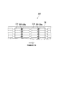
以下、図7を参照して、制御部6が行う処理について説明する。図7は、図1に示す制御部6が行う処理のフローチャートである。   Hereinafter, the process performed by the control unit 6 will be described with reference to FIG. FIG. 7 is a flowchart of processing performed by the control unit 6 shown in FIG.

まず、制御部6は、画像形成の開始の指示を受け付けると(ステップS101)、第1の負圧発生部336aの駆動を開始させる(ステップS102)。   First, when receiving an instruction to start image formation (step S101), the controller 6 starts driving the first negative pressure generator 336a (step S102).

次に、制御部6は、搬送ベルト32の移動(駆動)を開始させる(ステップS103)。具体的には、制御部6は、搬送ベルト32を正回転させる。すなわち、制御部6は、搬送ベルト32が用紙載置区間において用紙Pの搬送方向に移動するように、搬送ベルト32を回転させる。   Next, the control unit 6 starts to move (drive) the transport belt 32 (step S103). Specifically, the control unit 6 rotates the transport belt 32 forward. That is, the control unit 6 rotates the transport belt 32 so that the transport belt 32 moves in the transport direction of the paper P in the paper placement section.

その後、制御部6は、第1の負圧発生部336a及び搬送ベルト32が稼働された状態で、所定時間待機する(ステップS104)。所定時間は、例えば、搬送ベルト32が一回転するのに要する時間である。これにより、搬送ベルト32の稼働が停止されている間に搬送ベルト32の上面(特に、搬送ベルト32の用紙載置区間部分の上面)に堆積した紙粉が、第1の領域71の上方(本実施形態では、狭隙空間35a)を通過する際に、第1の空間331aに吸引されて搬送ベルト32の上面から除去される。   Thereafter, the control unit 6 waits for a predetermined time with the first negative pressure generating unit 336a and the conveyor belt 32 being operated (step S104). The predetermined time is, for example, the time required for the transport belt 32 to make one rotation. As a result, the paper dust accumulated on the upper surface of the conveyor belt 32 (particularly, the upper surface of the sheet placement section of the conveyor belt 32) while the operation of the conveyor belt 32 is stopped is above the first region 71 ( In the present embodiment, when passing through the narrow space 35 a), it is sucked into the first space 331 a and removed from the upper surface of the transport belt 32.

その後、制御部6は、第2の負圧発生部336bの駆動を開始させる(ステップS105)。   Thereafter, the controller 6 starts driving the second negative pressure generator 336b (step S105).

その後、制御部6は、用紙Pを搬送部31に搬送させて、記録ヘッド34に用紙Pへの画像の形成を行わせる(ステップS106)。   Thereafter, the control unit 6 causes the paper P to be transported to the transport unit 31, and causes the recording head 34 to form an image on the paper P (step S106).

画像形成が行われている間に紙詰まり(ジャム)の発生が検知された場合(ステップS107:YES)、制御部6は、用紙Pへの画像の形成を停止して(ステップS109)、処理をステップS110へ進める。   When occurrence of a paper jam (jam) is detected during image formation (step S107: YES), the control unit 6 stops image formation on the paper P (step S109), and processing is performed. To step S110.

一方、紙詰まりの発生が検知されずに(ステップS107:NO)用紙Pへの画像の形成が終了した場合(ステップS108:YES)、制御部6は、処理をステップS110へ進める。   On the other hand, when the occurrence of a paper jam is not detected (step S107: NO) and the image formation on the paper P is completed (step S108: YES), the control unit 6 advances the process to step S110.

ステップS110において、制御部6は、搬送ベルト32の移動を停止させる。   In step S110, the control unit 6 stops the movement of the conveyor belt 32.

その後、制御部6は、第2の負圧発生部336bの駆動を停止させる(ステップS111)。   Thereafter, the controller 6 stops driving the second negative pressure generator 336b (step S111).

その後、制御部6は、第1の負圧発生部336aの駆動を停止させ(ステップS112)、図7に示すフローチャートの処理を終了する。   Thereafter, the control unit 6 stops driving the first negative pressure generating unit 336a (step S112), and ends the process of the flowchart shown in FIG.

このように、インクジェット記録装置1は、画像形成を行う前に、第1の負圧発生部336a及び搬送ベルト32を所定時間稼働させて、画像形成空間よりも用紙Pの搬送方向の上流側において、搬送ベルト32上に堆積した紙粉を除去する処理(以下「事前紙粉除去処理」という)を行う。これにより、インクジェット記録装置1は、画像形成時に画像形成空間まで運ばれてくる紙粉の量を減らすことができ、紙粉のノズルへの付着を抑制することができる。   As described above, the ink jet recording apparatus 1 operates the first negative pressure generating unit 336a and the conveyance belt 32 for a predetermined time before image formation, and on the upstream side in the conveyance direction of the paper P from the image formation space. Then, a process of removing paper dust accumulated on the conveyor belt 32 (hereinafter referred to as “preliminary paper powder removal process”) is performed. Thereby, the inkjet recording apparatus 1 can reduce the amount of paper dust conveyed to the image forming space during image formation, and can suppress the adhesion of paper dust to the nozzle.

また、ステップS104の時点で、第2の負圧発生部336bは、未だ稼働されていない。したがって、ステップS104の時点で、第2の領域72の上方(画像形成空間)において、第2の空間331bへ向かう気流(吸引風)は発生していない。したがって、インクジェット記録装置1は、事前紙粉除去処理時に、画像形成空間における紙粉の舞い上がりを抑制し、紙粉のノズルへの付着を抑制することができる。   In addition, at the time of step S104, the second negative pressure generator 336b is not yet operated. Therefore, at the time of step S104, no airflow (suction airflow) toward the second space 331b is generated above the second region 72 (image forming space). Therefore, the ink jet recording apparatus 1 can suppress the paper dust from rising in the image forming space and prevent the paper dust from adhering to the nozzles during the preliminary paper dust removal process.

また、例えば、事前紙粉除去処理での搬送ベルト32の移動速度(ステップS104での搬送ベルト32の移動速度)は、画像形成時の搬送ベルト32の移動速度(ステップS106での搬送ベルト32の移動速度)よりも遅く設定される。また、事前紙粉除去処理において、搬送ベルト32の移動速度は、徐々に速くされる。これにより、事前紙粉除去処理において搬送ベルト32が急に動き出して或いは高速に動いて紙粉が飛散するという問題の発生が抑制される。   Further, for example, the moving speed of the conveying belt 32 in the pre-paper dust removal process (moving speed of the conveying belt 32 in step S104) is equal to the moving speed of the conveying belt 32 in image formation (the conveying belt 32 in step S106). It is set slower than (moving speed). Further, in the preliminary paper dust removal process, the moving speed of the conveyor belt 32 is gradually increased. Thereby, in the preliminary paper dust removal process, the occurrence of the problem that the conveying belt 32 suddenly starts moving or moves at high speed and the paper dust is scattered is suppressed.

以上、図面を参照しながら本発明の実施形態について説明した。ただし、本発明は、上記の実施形態に限られるものではなく、その要旨を逸脱しない範囲で種々の態様において実施することが可能である(例えば、下記に示す(1)〜(6))。図面は、理解し易くするために、それぞれの構成要素を主体に模式的に示しており、図示された各構成要素の厚み、長さ、個数等は、図面作成の都合上から実際とは異なる場合がある。また、上記の実施形態で示す各構成要素の形状、寸法等は一例であって、特に限定されるものではなく、本発明の構成から実質的に逸脱しない範囲で種々の変更が可能である。   The embodiments of the present invention have been described above with reference to the drawings. However, the present invention is not limited to the above-described embodiment, and can be implemented in various modes without departing from the gist thereof (for example, (1) to (6) shown below). For ease of understanding, the drawings schematically show each component as a main component, and the thickness, length, number, etc. of each component shown in the drawings are different from the actual for convenience of drawing. There is a case. Moreover, the shape, dimension, etc. of each component shown by said embodiment are an example, Comprising: It does not specifically limit, A various change is possible in the range which does not deviate substantially from the structure of this invention.

(1)本実施形態では、記録ヘッド34よりも用紙Pの搬送方向上流側であって第1の領域71に対応する位置に板状部材35が設けられたが、板状部材35が設けられない形態でもよい。   (1) In the present embodiment, the plate-like member 35 is provided at the position corresponding to the first region 71 on the upstream side of the recording head 34 in the transport direction of the paper P. However, the plate-like member 35 is provided. There may be no form.

(2)本実施形態では、空気流通室331は、2つの空間(第1の空間331a及び第2の空間331b)に仕切られていたが、空気流通室331を仕切らない形態でもよい。   (2) In this embodiment, the air circulation chamber 331 is partitioned into two spaces (the first space 331a and the second space 331b), but the air circulation chamber 331 may not be partitioned.

(3)本実施形態では、事前紙粉除去処理において、搬送ベルト32は、正回転されたが、逆回転されてもよい。すなわち、制御部6は、ステップS103において、搬送ベルト32が用紙載置区間において用紙Pの搬送方向の逆方向(第2の方向)に移動するように、搬送ベルト32を回転させてもよい。この場合、制御部6は、ステップS106を行う前に、搬送ベルト32の回転方向を、逆回転から正回転へ変更する。事前紙粉除去処理において搬送ベルト32が逆回転されることにより、第2の領域72の上方における搬送ベルト32上の紙粉が、正回転の場合よりも早く第1の領域71の上方まで搬送されて除去される。よって、インクジェット記録装置1は、搬送ベルト32の用紙載置区間部分の上面に堆積した紙粉をより早く除去することができる。   (3) In the present embodiment, in the pre-paper dust removal process, the transport belt 32 is rotated forward, but may be rotated backward. That is, in step S103, the control unit 6 may rotate the transport belt 32 so that the transport belt 32 moves in the direction opposite to the transport direction of the paper P (second direction) in the paper placement section. In this case, the control unit 6 changes the rotation direction of the conveyor belt 32 from reverse rotation to normal rotation before performing Step S106. By the reverse rotation of the transport belt 32 in the pre-paper dust removal process, the paper dust on the transport belt 32 above the second region 72 is transported to the upper portion of the first region 71 earlier than in the case of normal rotation. To be removed. Therefore, the ink jet recording apparatus 1 can remove paper dust accumulated on the upper surface of the paper placement section of the transport belt 32 more quickly.

(4)本実施形態では、画像形成部3において搬送ベルト32が用紙Pを搬送する場合について説明したが、画像形成部3においてその他の方法で用紙Pを搬送する形態でもよい。例えば、複数の搬送ローラーによって用紙Pを搬送する形態でもよい。この場合には、互いに隣接する搬送ローラーの間から負圧を印加することが好ましい。   (4) In this embodiment, the case where the conveyance belt 32 conveys the paper P in the image forming unit 3 has been described. However, the image forming unit 3 may convey the paper P by other methods. For example, the paper P may be transported by a plurality of transport rollers. In this case, it is preferable to apply a negative pressure from between adjacent conveyance rollers.

(5)本実施形態では、狭隙空間35aが板状部材35によって形成される場合について説明したが、狭隙空間35aをその他の方法で形成する形態でもよい。例えば、記録ヘッド34に対して用紙Pの搬送方向上流側において、ヘッドベース37が搬送ベルト32側に突出して形成され、狭隙空間35aを形成する形態でもよい。この場合には、構造を簡略化することができる。   (5) Although the case where the narrow space 35a is formed by the plate-like member 35 has been described in the present embodiment, the narrow space 35a may be formed by other methods. For example, the head base 37 may be formed so as to protrude toward the transport belt 32 on the upstream side in the transport direction of the paper P with respect to the recording head 34 to form the narrow space 35a. In this case, the structure can be simplified.

また、板状部材35に換えて、2つのローラーに張架されたベルトによって狭隙空間35aを形成する形態でもよい。具体的には、搬送ベルト32の上面と略平行な位置に配置された駆動ローラー及び従動ローラーと、上記駆動ローラー及び上記従動ローラーに張架された無端ベルトとを備え、上記無端ベルトの下面と、搬送ベルト32の上面との間で狭隙空間35aを形成する。この場合には、上記無端ベルトの下面に紙粉が付着したときに、紙粉が付着していない面が下側に位置するように上記無端ベルトを回転駆動させることができるため、サービスマン等が上記無端ベルトに付着した紙粉を除去する頻度を減少することができる。   Further, instead of the plate-like member 35, the narrow space 35a may be formed by a belt stretched around two rollers. Specifically, the driving roller and the driven roller disposed at a position substantially parallel to the upper surface of the transport belt 32, and an endless belt stretched between the driving roller and the driven roller, the lower surface of the endless belt, A narrow gap space 35 a is formed between the upper surface of the conveyor belt 32. In this case, when the paper dust adheres to the lower surface of the endless belt, the endless belt can be driven to rotate so that the surface to which the paper dust does not adhere is located on the lower side. However, the frequency of removing the paper dust adhering to the endless belt can be reduced.

(6)本実施形態では、ガイド部材332と空気流通室331とが別部材である場合について説明したが、ガイド部材332と空気流通室331とが一体に形成されている形態でもよい。この場合には、空気流通室331からの負圧のリーク(ガイド部材332と空気流通室331との間の隙間からの空気流通室331への空気の流入)を防止することができる。   (6) Although the case where the guide member 332 and the air circulation chamber 331 are separate members has been described in the present embodiment, the guide member 332 and the air circulation chamber 331 may be integrally formed. In this case, leak of negative pressure from the air circulation chamber 331 (inflow of air into the air circulation chamber 331 from the gap between the guide member 332 and the air circulation chamber 331) can be prevented.

本発明は、インクジェット記録装置に利用可能である。   The present invention is applicable to an ink jet recording apparatus.

1 インクジェット記録装置
2 給紙部
3 画像形成部
31 搬送部
312 吸着ローラー
32 搬送ベルト
321 吸引孔
33 負圧印加部
331 空気流通室
332 ガイド部材(搬送板)
334 溝
335 貫通孔
335a、335b テーパ
336 負圧発生部
34(34a、34b、34c、34d) 記録ヘッド
35 板状部材(空間形成部)
351 テーパ
35a 狭隙空間
36 搬送ガイド
37 ヘッドベース(空間形成部)
371、372 孔
6 制御部
DESCRIPTION OF SYMBOLS 1 Inkjet recording device 2 Paper feeding part 3 Image forming part 31 Conveying part 312 Adsorption roller 32 Conveying belt 321 Suction hole 33 Negative pressure application part 331 Air circulation chamber 332 Guide member (conveying plate)
334 Groove 335 Through-hole 335a, 335b Taper 336 Negative pressure generating part 34 (34a, 34b, 34c, 34d) Recording head 35 Plate member (space forming part)
351 Taper 35a Narrow space 36 Transport guide 37 Head base (space forming part)
371, 372 hole 6 control unit

Claims (13)

制御部と、
第1の方向に移動する搬送ベルトに記録媒体を載せて搬送する搬送部と、
前記搬送部により搬送される前記記録媒体にインクを吐出して画像を形成する記録ヘッドと、
前記記録媒体を吸引するための負圧が発生される空気流通室を備え、前記空気流通室の上壁及び前記搬送ベルトのそれぞれに形成される複数の孔を介して前記記録媒体を前記負圧により吸引し、前記記録媒体を前記搬送ベルトの上面である前記記録媒体の載置面に吸着させる負圧印加部と
を備え、
前記負圧印加部は、
前記空気流通室の底面上の第1の領域に設けられ、前記空気流通室に負圧を発生させる第1の負圧発生部と、
前記空気流通室の底面上の第2の領域に設けられ、前記空気流通室に負圧を発生させる第2の負圧発生部と
を更に備え、
前記第1の領域は、前記搬送ベルト及び前記上壁を介して前記記録ヘッドに対向する前記底面上のヘッド対向領域よりも前記第1の方向の上流側の所定の領域であり、
前記第2の領域は、前記第1の領域よりも前記第1の方向の下流側の領域であって前記ヘッド対向領域を含む領域であり、
前記制御部は、画像形成の開始の指示を受け付けた場合、以下の(1)〜(4)の処理を当該順序で行う、
(1)前記第1の負圧発生部の駆動を開始させる、
(2)前記搬送ベルトの移動を開始させた後、所定時間待機する、
(3)前記第2の負圧発生部の駆動を開始させる、
(4)前記記録媒体を前記搬送部に搬送させて、前記記録ヘッドに前記記録媒体への画像の形成を行わせる、
インクジェット記録装置。
A control unit;
A transport unit that transports the recording medium on a transport belt that moves in a first direction;
A recording head that forms an image by ejecting ink onto the recording medium conveyed by the conveying unit;
An air circulation chamber for generating a negative pressure for sucking the recording medium is provided, and the negative pressure is applied to the recording medium through a plurality of holes formed in an upper wall of the air circulation chamber and the conveying belt. A negative pressure applying unit that sucks the recording medium onto the mounting surface of the recording medium that is the upper surface of the conveyance belt,
The negative pressure application unit is
A first negative pressure generator provided in a first region on a bottom surface of the air circulation chamber, and generating a negative pressure in the air circulation chamber;
A second negative pressure generator provided in a second region on the bottom surface of the air circulation chamber and generating a negative pressure in the air circulation chamber;
The first area is a predetermined area upstream of the head facing area on the bottom surface facing the recording head via the transport belt and the upper wall in the first direction.
The second region is a region downstream of the first region in the first direction and including the head facing region,
When the control unit receives an instruction to start image formation, the control unit performs the following processes (1) to (4) in that order.
(1) Start driving the first negative pressure generating unit;
(2) Wait for a predetermined time after starting the movement of the conveyor belt;
(3) Start driving the second negative pressure generating unit;
(4) The recording medium is conveyed to the conveyance unit, and the recording head is caused to form an image on the recording medium.
Inkjet recording device.
前記搬送ベルトは、回転駆動され、
前記所定時間は、前記搬送ベルトが一回転するのに要する時間である、請求項1に記載のインクジェット記録装置。
The conveyor belt is rotationally driven,
The inkjet recording apparatus according to claim 1, wherein the predetermined time is a time required for the conveyance belt to make one rotation.
前記(2)における前記搬送ベルトの移動速度は、前記(4)における前記搬送ベルトの移動速度よりも遅い、請求項1又は2に記載のインクジェット記録装置。
3. The ink jet recording apparatus according to claim 1, wherein a moving speed of the conveying belt in (2) is slower than a moving speed of the conveying belt in (4).
前記制御部は、前記(2)において、前記搬送ベルトを前記第1の方向又は前記第1の方向とは逆の第2の方向へ移動させる、請求項1〜3のうちのいずれかに記載のインクジェット記録装置。
The control unit according to any one of claims 1 to 3, wherein in (2), the control unit moves the conveyor belt in the first direction or a second direction opposite to the first direction. Inkjet recording apparatus.
前記制御部は、前記記録媒体への画像の形成が終了した後、以下の(5)〜(7)の処理を当該順序で行う、
(5)前記搬送ベルトの移動を停止させる、
(6)前記第2の負圧発生部の駆動を停止させる、
(7)前記第1の負圧発生部の駆動を停止させる、
請求項1〜4のうちのいずれかに記載のインクジェット記録装置。
The control unit performs the following processes (5) to (7) in this order after the image formation on the recording medium is completed.
(5) stop the movement of the conveyor belt;
(6) Stop driving of the second negative pressure generating unit,
(7) Stop driving the first negative pressure generating unit;
The ink jet recording apparatus according to claim 1.
前記制御部は、前記記録媒体の搬送に関して異常が発生した場合、以下の(5)〜(7)の処理を当該順序で行って、前記記録媒体への画像の形成を停止する、
(5)前記搬送ベルトの移動を停止させる、
(6)前記第2の負圧発生部の駆動を停止させる、
(7)前記第1の負圧発生部の駆動を停止させる、
請求項1〜4のうちのいずれかに記載のインクジェット記録装置。
When an abnormality occurs with respect to the conveyance of the recording medium, the control unit performs the following processes (5) to (7) in the order, and stops image formation on the recording medium.
(5) stop the movement of the conveyor belt;
(6) Stop driving of the second negative pressure generating unit,
(7) Stop driving the first negative pressure generating unit;
The ink jet recording apparatus according to claim 1.
前記空気流通室が第1の空間と第2の空間とに仕切られており、
前記底面の前記第1の空間を形成する部分は、前記第1の領域を含み、
前記底面の前記第2の空間を形成する部分は、前記第2の領域を含む、請求項1〜6のうちのいずれかに記載のインクジェット記録装置。
The air circulation chamber is partitioned into a first space and a second space;
The portion of the bottom surface forming the first space includes the first region,
The ink jet recording apparatus according to claim 1, wherein a portion of the bottom surface forming the second space includes the second region.
前記記録ヘッドよりも前記記録媒体の搬送方向上流側であって前記第1の領域に対応する位置において、前記載置面との間で狭隙空間を形成する空間形成部を更に備え、
前記狭隙空間は、前記狭隙空間の周囲の空間から前記狭隙空間に流入する空気流の速度を、前記狭隙空間に流入する前より、前記狭隙空間に流入した後の方が大きくするように、前記載置面に直交する方向の距離が設定されている、請求項1〜7のうちのいずれかに記載のインクジェット記録装置。
A space forming part that forms a narrow space with the mounting surface at a position corresponding to the first region on the upstream side of the recording medium in the transport direction of the recording medium;
In the narrow space, the velocity of the air flow flowing into the narrow space from the space around the narrow space is greater after flowing into the narrow space than before flowing into the narrow space. The inkjet recording apparatus according to any one of claims 1 to 7, wherein a distance in a direction perpendicular to the placement surface is set.
前記空間形成部は、前記狭隙空間における前記載置面に直交する方向の距離が予め設定された閾値距離以下となるように前記狭隙空間を形成する、請求項8に記載のインクジェット記録装置。
The inkjet recording apparatus according to claim 8, wherein the space forming unit forms the narrow space so that a distance in a direction perpendicular to the placement surface in the narrow space is equal to or less than a preset threshold distance. .
前記空間形成部は、前記搬送部における前記記録媒体の載置面と対向し、前記記録媒体の載置面と略平行な平面を有する板状部材である、請求項8又は9に記載のインクジェット記録装置。
10. The inkjet according to claim 8, wherein the space forming unit is a plate-like member that faces a mounting surface of the recording medium in the transport unit and has a plane substantially parallel to the mounting surface of the recording medium. Recording device.
前記板状部材は、接地された導電体である、請求項10に記載のインクジェット記録装置。
The inkjet recording apparatus according to claim 10, wherein the plate-like member is a grounded conductor.
前記記録ヘッドを支持するヘッドベースを備え、
前記板状部材は、前記ヘッドベースに固定され、
前記ヘッドベースは、前記板状部材よりも前記記録媒体の搬送方向上流側、及び、前記記録媒体の搬送方向下流側に、前記狭隙空間に空気を流入させる孔が形成されている、請求項10又は11に記載のインクジェット記録装置。
A head base for supporting the recording head;
The plate-like member is fixed to the head base,
The head base is formed with holes through which air flows into the narrow gap space on the upstream side in the conveyance direction of the recording medium and on the downstream side in the conveyance direction of the recording medium with respect to the plate-like member. The ink jet recording apparatus according to 10 or 11.
前記板状部材には、前記狭隙空間における前記載置面に直交する方向の距離が、前記板状部材における前記記録媒体の搬送方向の端面に近づく程大きくなるようにテーパが形成されている、請求項10〜12のうちのいずれか1項に記載のインクジェット記録装置。   The plate-like member is tapered so that the distance in the direction perpendicular to the mounting surface in the narrow gap space increases as it approaches the end surface of the plate-like member in the conveyance direction of the recording medium. An ink jet recording apparatus according to any one of claims 10 to 12.
JP2014244797A 2014-12-03 2014-12-03 Inkjet recording device Active JP6237595B2 (en)

Priority Applications (1)

Application Number Priority Date Filing Date Title
JP2014244797A JP6237595B2 (en) 2014-12-03 2014-12-03 Inkjet recording device

Applications Claiming Priority (1)

Application Number Priority Date Filing Date Title
JP2014244797A JP6237595B2 (en) 2014-12-03 2014-12-03 Inkjet recording device

Publications (2)

Publication Number Publication Date
JP2016107437A JP2016107437A (en) 2016-06-20
JP6237595B2 true JP6237595B2 (en) 2017-11-29

Family

ID=56121586

Family Applications (1)

Application Number Title Priority Date Filing Date
JP2014244797A Active JP6237595B2 (en) 2014-12-03 2014-12-03 Inkjet recording device

Country Status (1)

Country Link
JP (1) JP6237595B2 (en)

Families Citing this family (2)

* Cited by examiner, † Cited by third party
Publication number Priority date Publication date Assignee Title
JP7064837B2 (en) * 2017-09-21 2022-05-11 理想科学工業株式会社 Inkjet printing equipment and transport equipment
JP2019107808A (en) * 2017-12-15 2019-07-04 三菱重工機械システム株式会社 Printer and printing control method

Family Cites Families (5)

* Cited by examiner, † Cited by third party
Publication number Priority date Publication date Assignee Title
JP4493325B2 (en) * 2003-12-04 2010-06-30 オリンパス株式会社 Image recording device
JP2005169990A (en) * 2003-12-15 2005-06-30 Olympus Corp Image forming apparatus
JP4785172B2 (en) * 2004-07-30 2011-10-05 理想科学工業株式会社 Image recording device
JP2007152762A (en) * 2005-12-06 2007-06-21 Fujifilm Corp Image recording device
US8523317B2 (en) * 2009-04-28 2013-09-03 Xerox Corporation Pneumatic hole cleaner for vacuum belt

Also Published As

Publication number Publication date
JP2016107437A (en) 2016-06-20

Similar Documents

Publication Publication Date Title
JP6081977B2 (en) Inkjet recording device
JP6274091B2 (en) Inkjet recording device
JP6237595B2 (en) Inkjet recording device
JP6237603B2 (en) Inkjet recording device
JP6337763B2 (en) Inkjet recording device
JP6344220B2 (en) Inkjet recording device
JP2016094291A (en) Inkjet recorder
JP6217602B2 (en) Inkjet recording device
JP6327126B2 (en) Inkjet recording device
JP6038198B2 (en) Inkjet recording device
JP6222060B2 (en) Inkjet recording device
JP6350346B2 (en) Inkjet recording device
JP6213448B2 (en) Inkjet recording device
JP6038199B2 (en) Inkjet recording device
JP6303989B2 (en) Inkjet recording device
JP6337805B2 (en) Inkjet recording device
JP6248905B2 (en) Inkjet recording device
JP5990289B2 (en) Inkjet recording device
JP6311583B2 (en) Inkjet recording device
JP6369358B2 (en) Inkjet recording device
JP6252460B2 (en) Inkjet recording device
JP6399190B2 (en) Inkjet recording device
JP6252467B2 (en) Inkjet recording device
JP6323370B2 (en) Inkjet recording device
JP2016097583A (en) Inkjet recorder

Legal Events

Date Code Title Description
A621 Written request for application examination

Free format text: JAPANESE INTERMEDIATE CODE: A621

Effective date: 20161226

A977 Report on retrieval

Free format text: JAPANESE INTERMEDIATE CODE: A971007

Effective date: 20170925

TRDD Decision of grant or rejection written
A01 Written decision to grant a patent or to grant a registration (utility model)

Free format text: JAPANESE INTERMEDIATE CODE: A01

Effective date: 20171003

A61 First payment of annual fees (during grant procedure)

Free format text: JAPANESE INTERMEDIATE CODE: A61

Effective date: 20171016

R150 Certificate of patent or registration of utility model

Ref document number: 6237595

Country of ref document: JP

Free format text: JAPANESE INTERMEDIATE CODE: R150