JP6236770B2 - Plastic container - Google Patents
Plastic container Download PDFInfo
- Publication number
- JP6236770B2 JP6236770B2 JP2012250296A JP2012250296A JP6236770B2 JP 6236770 B2 JP6236770 B2 JP 6236770B2 JP 2012250296 A JP2012250296 A JP 2012250296A JP 2012250296 A JP2012250296 A JP 2012250296A JP 6236770 B2 JP6236770 B2 JP 6236770B2
- Authority
- JP
- Japan
- Prior art keywords
- plastic container
- convex
- rib
- concave
- ribs
- Prior art date
- Legal status (The legal status is an assumption and is not a legal conclusion. Google has not performed a legal analysis and makes no representation as to the accuracy of the status listed.)
- Active
Links
Images


Classifications
-
- Y—GENERAL TAGGING OF NEW TECHNOLOGICAL DEVELOPMENTS; GENERAL TAGGING OF CROSS-SECTIONAL TECHNOLOGIES SPANNING OVER SEVERAL SECTIONS OF THE IPC; TECHNICAL SUBJECTS COVERED BY FORMER USPC CROSS-REFERENCE ART COLLECTIONS [XRACs] AND DIGESTS
- Y02—TECHNOLOGIES OR APPLICATIONS FOR MITIGATION OR ADAPTATION AGAINST CLIMATE CHANGE
- Y02E—REDUCTION OF GREENHOUSE GAS [GHG] EMISSIONS, RELATED TO ENERGY GENERATION, TRANSMISSION OR DISTRIBUTION
- Y02E60/00—Enabling technologies; Technologies with a potential or indirect contribution to GHG emissions mitigation
- Y02E60/10—Energy storage using batteries
Landscapes
- Containers Having Bodies Formed In One Piece (AREA)
Description
本発明は、主として飲料や調味料等の内容液を収容するプラスチック製容器に関する。 The present invention mainly relates to a plastic container for storing content liquids such as beverages and seasonings.
従来、プラスチック製容器内に内容物を充填し、閉栓した後、充填時の温度と保管時の温度との違いにより、容器内が減圧したり増圧したりすることが知られている。 Conventionally, after filling a plastic container with contents and closing the container, it is known that the inside of the container is depressurized or increased depending on the difference between the filling temperature and the storage temperature.
例えば、殺菌のために高温の液体を容器に充填し、容器を閉栓したのちに室温まで冷却すると、容器内は減圧する。また常温で充填した場合でも、充填される液体が例えば緑茶からなる場合、緑茶と容器のヘッドスペース内の空気に含まれる酸素とが化学反応することにより、ヘッドスペースの空気の体積が減り、これによっても容器内が減圧する。 For example, when a container is filled with a high-temperature liquid for sterilization and the container is closed and then cooled to room temperature, the inside of the container is depressurized. In addition, even when filled at room temperature, if the liquid to be filled is made of green tea, for example, the green space and oxygen contained in the air in the head space of the container will chemically react to reduce the volume of air in the head space. The pressure in the container is also reduced.
逆に、内容液が充填された容器を販売時に加温した場合、容器内は増圧する。 Conversely, when the container filled with the content liquid is heated at the time of sale, the inside of the container is increased in pressure.
このような容器内の減圧または増圧に対応するため、例えば容器の胴部にパネルを設けることが行われている(例えば特許文献1)。この場合、容器内の減圧(または増圧)に追従して変形しやすいようにパネルに微細な凹凸を設けたり、または意匠性のために微細な凹凸を設けるなど様々な形態があるが、何れも容器の胴部にほぼ平板状のパネルを複数設けることが一般的である。 In order to cope with such pressure reduction or pressure increase in the container, for example, a panel is provided on the body of the container (for example, Patent Document 1). In this case, there are various forms such as providing fine unevenness on the panel so as to easily deform following the reduced pressure (or increasing pressure) in the container, or providing fine unevenness for design. In general, a plurality of substantially flat panels are provided on the body of the container.
しかしながら、このようなパネルを有する容器に垂直方向または水平方向の荷重が加えられたとき、容器はこれらの荷重をパネルとパネルの間の部分(柱)でしか受け止めることができない。このため、パネルを有する容器は、垂直方向または水平方向の荷重に対して強度が弱くなるという欠点がある。 However, when vertical or horizontal loads are applied to a container having such a panel, the container can only accept these loads at the portion (column) between the panels. For this reason, the container which has a panel has the fault that intensity | strength becomes weak with respect to the load of a perpendicular direction or a horizontal direction.
ところで、このように容器の強度が不足すると、次のような問題が生じる。まず容器の垂直方向の荷重に耐える強度(座屈強度)が不足すると、容器を積み上げて倉庫等で保管するとき、または輸送するとき、荷積みされた下段の容器が変形し、荷崩れが生じる恐れがある。 By the way, when the strength of the container is insufficient, the following problems occur. First, if the container is not strong enough to withstand the load in the vertical direction (buckling strength), when the container is stacked and stored in a warehouse or transported, the loaded lower container is deformed and collapses. There is a fear.
また、容器の水平方向の荷重に耐える強度(側壁強度)が不足すると、自動販売機内に容器が横向きに投入された際、積み上げられた容器が変形し、容器が自動販売機から正常に排出されなくなるという問題がある。また、容器を手で把持して開栓するとき、容器を手で握りつぶすことにより内容液が飛び出る恐れもある。 Also, if the container is not strong enough to withstand the horizontal load (side wall strength), when the container is loaded horizontally into the vending machine, the stacked container is deformed and the container is normally discharged from the vending machine. There is a problem of disappearing. In addition, when the container is grasped by hand and opened, there is a possibility that the content liquid may pop out by being crushed by the hand.
一方、近年、コスト低減や石油資源の節約などのため、プラスチック製容器が軽量化される傾向にある。 On the other hand, in recent years, plastic containers tend to be reduced in weight in order to reduce costs and save petroleum resources.
このため、容器の胴部にパネルを設ける代わりに、胴部に周方向に延びる多数の補強溝を設けた容器も知られている(例えば特許文献2)。 For this reason, a container is also known in which a number of reinforcing grooves extending in the circumferential direction are provided in the body instead of providing a panel in the body of the container (for example, Patent Document 2).
このような容器は、上述したパネルを有する容器よりも座屈強度や側壁強度に優れるのが特徴のひとつである。しかしながら、容器内の減圧や増圧に十分対応する手段を持たないため、減圧や増圧により容器が歪な形に変形するという問題を有している。 One of the features of such a container is that it has better buckling strength and side wall strength than the container having the above-described panel. However, there is a problem that the container is deformed into a distorted shape due to pressure reduction or pressure increase because there is no means for sufficiently responding to pressure reduction or pressure increase in the container.
本発明はこのような点を考慮してなされたものであり、座屈強度および側壁強度に優れ、かつ容器内が減圧または増圧された場合であっても、その圧力の変動を吸収することが可能な、プラスチック製容器を提供することを目的とする。 The present invention has been made in consideration of such points, and is excellent in buckling strength and side wall strength, and absorbs fluctuations in pressure even when the inside of the container is depressurized or increased. An object of the present invention is to provide a plastic container.
本発明は、プラスチック製容器において、口部と、肩部と、胴部と、底部とを備え、胴部は、円周方向に沿って配置された複数の圧力吸収パネルと、各圧力吸収パネル間に配置され、垂直方向に延びる垂直支柱とを有し、各圧力吸収パネル内に、外方に突出する複数の凸状リブと、各凸状リブ間に位置する凹状リブとが設けられ、各凸状リブおよび各凹状リブは、それぞれ圧力吸収パネルの一端から他端までV字状に延びることを特徴とするプラスチック製容器である。 In the plastic container, the present invention includes a mouth portion, a shoulder portion, a body portion, and a bottom portion, and the body portion includes a plurality of pressure absorption panels arranged along the circumferential direction, and each pressure absorption panel. A plurality of convex ribs projecting outwardly and concave ribs positioned between the convex ribs, each having a vertical column extending in the vertical direction and provided in each pressure absorbing panel; Each convex rib and each concave rib is a plastic container characterized by extending in a V shape from one end to the other end of the pressure absorbing panel.
本発明は、凸状リブおよび凹状リブは、各圧力吸収パネルの垂直方向全域にわたって形成されていることを特徴とするプラスチック製容器である。 The present invention is the plastic container, wherein the convex rib and the concave rib are formed over the entire vertical direction of each pressure absorbing panel.
本発明は、凸状リブは、その表面に平坦面を有することを特徴とするプラスチック製容器である。 The present invention is the plastic container characterized in that the convex rib has a flat surface on the surface thereof.
本発明は、凹状リブは、その内部に平坦面を有することを特徴とするプラスチック製容器である。 The present invention is the plastic container characterized in that the concave rib has a flat surface inside.
本発明は、各圧力吸収パネルにおいて、複数の凸状リブは、互いに同一の幅を有することを特徴とするプラスチック製容器である。 The present invention is the plastic container characterized in that, in each pressure absorption panel, the plurality of convex ribs have the same width.
本発明は、各圧力吸収パネルにおいて、複数の凸状リブは、互いに異なる幅を有することを特徴とするプラスチック製容器である。 The present invention is the plastic container, wherein each of the pressure absorbing panels has a plurality of convex ribs having different widths.
本発明は、胴部は、圧力吸収パネルの上方において水平方向に延びる上部水平支柱と、圧力吸収パネルの下方において水平方向に延びる下部水平支柱とを有することを特徴とするプラスチック製容器である。 The present invention is the plastic container characterized in that the body portion has an upper horizontal column extending in the horizontal direction above the pressure absorption panel and a lower horizontal column extending in the horizontal direction below the pressure absorption panel.
本発明は、肩部と上部水平支柱との間に、水平方向に延びる上部補強溝が設けられ、底部と下部水平支柱との間に、水平方向に延びる下部補強溝が設けられていることを特徴とするプラスチック製容器である。 According to the present invention, an upper reinforcing groove extending in the horizontal direction is provided between the shoulder portion and the upper horizontal column, and a lower reinforcing groove extending in the horizontal direction is provided between the bottom portion and the lower horizontal column. It is a characteristic plastic container.
本発明は、凸状リブの突出高さをdとし、凸状リブの肉厚をtとしたとき、t≦d≦10tという関係が成立することを特徴とするプラスチック製容器である。 The present invention is a plastic container characterized in that a relationship of t ≦ d ≦ 10 t is established, where d is the protruding height of the convex rib and t is the thickness of the convex rib.
本発明は、各凸状リブおよび各凹状リブは、それぞれ下に凸の形状を有することを特徴とするプラスチック製容器である。 The present invention is the plastic container, wherein each convex rib and each concave rib has a convex shape downward.
本発明は、各凸状リブおよび各凹状リブは、それぞれ上に凸の形状を有することを特徴とするプラスチック製容器である。 The present invention is the plastic container characterized in that each convex rib and each concave rib has a convex shape upward.
本発明によれば、各圧力吸収パネル内に、外方に突出する複数の凸状リブと、各凸状リブ間に位置する凹状リブとが設けられ、各凸状リブおよび各凹状リブは、それぞれ圧力吸収パネルの一端から他端までV字状に延びている。このことにより、プラスチック製容器の座屈強度および側壁強度を高めるとともに、容器内が減圧または増圧された場合であっても、その圧力の変動を吸収することができる。 According to the present invention, each pressure absorbing panel is provided with a plurality of convex ribs projecting outward and concave ribs positioned between the convex ribs, and each convex rib and each concave rib are Each of the pressure absorbing panels extends in a V shape from one end to the other end. As a result, the buckling strength and side wall strength of the plastic container can be increased, and even when the inside of the container is depressurized or increased, fluctuations in the pressure can be absorbed.
以下、図面を参照して本発明の一実施の形態について説明する。図1乃至図5は本発明の一実施の形態を示す図である。 Hereinafter, an embodiment of the present invention will be described with reference to the drawings. 1 to 5 are views showing an embodiment of the present invention.
まず、図1乃至図5により、本実施の形態によるプラスチック製容器の概要について説明する。なお、本明細書中、「上方」、「下方」、「垂直方向」および「水平方向」とは、それぞれプラスチック製容器10を正立させた状態(図1)における上方、下方、垂直方向および水平方向のことをいう。
First, an outline of a plastic container according to the present embodiment will be described with reference to FIGS. In the present specification, “upward”, “downward”, “vertical direction”, and “horizontal direction” refer to the upward, downward, vertical, and vertical directions in the state in which the
図1乃至図5に示すプラスチック製容器10は、射出成形により得られるプリフォームを準備し、このプリフォームに対して二軸延伸ブロー成形を施すことにより作製される。このようなプラスチック製容器10は、例えば全高が120mm〜140mm、最大胴径がφ60〜70mm、満注容量が250ml〜350mlのボトルからなっていても良い。一例として、本実施の形態によるプラスチック製容器10は、その全高が132mm、その最大胴径がφ66mm、その満注容量が300mlである。
The
このようなプラスチック製容器10は、口部11と、口部11下方に設けられた肩部12と、肩部12下方に設けられた胴部20と、胴部20下方に設けられた底部30とを備えている。
Such a
このうち胴部20は、円周方向に沿って等間隔に配置された複数(6個)の圧力吸収パネル40と、各圧力吸収パネル40間に配置され、垂直方向に延びる複数(6本)の垂直支柱21とを有している。
Among these, the trunk |
なお、胴部20に設けられる圧力吸収パネル40および垂直支柱21の数は、それぞれ6に限られるものではなく、例えば3〜12としても良い。また、本実施の形態において、全ての圧力吸収パネル40が同一の形状および寸法を有している。しかしながら、これに限られるものではなく、必ずしも全ての圧力吸収パネル40の形状および/または寸法が同一でなくても良い。
In addition, the number of the
また、胴部20のうち、圧力吸収パネル40の上方には、水平方向(円周方向)に延びる上部水平支柱22が設けられ、圧力吸収パネル40の下方には、水平方向(円周方向)に延びる下部水平支柱23が設けられている。なお、上述した6本の垂直支柱21と、上部水平支柱22と、下部水平支柱23とにより、胴部20の略円筒状の外周面20aが構成されている。
Further, an upper
さらに、肩部12と上部水平支柱22との間に、水平方向(円周方向)に延びる上部補強溝24が設けられている。また、底部30と下部水平支柱23との間に、水平方向(円周方向)に延びる下部補強溝25が設けられている。
Further, an upper reinforcing
これら上部補強溝24および下部補強溝25は、それぞれ周方向全域に亘って延びている。これら上部補強溝24および下部補強溝25は、胴部20のうち比較的変形しやすい部分である肩部12および底部30の周辺領域の強度を高める役割を果たす。
Each of the upper reinforcing
次に圧力吸収パネル40について、図1及び図4を用いて説明する。
Next, the
圧力吸収パネル40は、プラスチック製容器10内に内容物を充填し、閉栓した後、充填時の温度と保管時の温度との違いにより、プラスチック製容器10内が減圧されたり増圧されたりする際の圧力差を吸収するものである。
The
この圧力吸収パネル40の内部には、外方に突出するとともにV字状に延びる複数の凸状リブ41が設けられている。また、各凸状リブ41間には、それぞれV字状に延びる凹状リブ42が形成されている。各凸状リブ41および各凹状リブ42は、それぞれ圧力吸収パネル40の一端(左端)40aから他端(右端)40bまで連続的に延びている。すなわち、凸状リブ41および凹状リブ42は、隣り合う垂直支柱21同士を連結している。
A plurality of
この場合、各凸状リブ41および各凹状リブ42は、それぞれ下に凸のV字形状を有している。また、図1に示すように、各凸状リブ41および各凹状リブ42のV字を構成する左右の傾斜部分の、水平線に対する角度をαとしたとき、角度αは、5°≦α≦45°、望ましくは10°≦α≦30°とすることが好ましい。角度αをこの範囲とすることにより、プラスチック製容器10の座屈強度および側壁強度を高める効果が得られやすい。なお、本実施の形態において、全ての圧力吸収パネル40において凸状リブ41および凹状リブ42の角度αを同一としているが、必ずしも全ての圧力吸収パネル40において角度αを同一としなくても良い。
In this case, each
これら凸状リブ41と凹状リブ42とは、垂直方向(上下方向)にわたって交互に配置されている。この場合、凸状リブ41および凹状リブ42は、各圧力吸収パネル40の上端40cから下端40dまで(後述する接続面43を除く)垂直方向全域にわたって形成されている。
The
なお、凸状リブ41および凹状リブ42は、各圧力吸収パネル40の垂直方向全域に設けられる場合に限られない。凸状リブ41および凹状リブ42は、各圧力吸収パネル40の一部、例えば各圧力吸収パネル40の上半分、下半分又は垂直方向中央部のみに設けられていても良い。
The
また、凸状リブ41および凹状リブ42の周囲を取り囲むように接続面43が設けられている。この接続面43は、胴部20の外周面20a(垂直支柱21、上部水平支柱22又は下部水平支柱23)と、凸状リブ41又は凹状リブ42との間に設けられており、外周面20aに対して傾斜している。
In addition, a
なお、凸状リブ41および凹状リブ42は、各々が少なくとも4本以上配置されていることが望ましい。この理由は以下の通りである。すなわち、圧力吸収パネル40は、プラスチック製容器10内が減圧された際、容器10の内方に凹むことにより、プラスチック製容器10全体の変形を防止する役割を果たす。凸状リブ41および凹状リブ42を各々4本以上とすることにより、減圧吸収機能を十分発揮することができるからである。更に、プラスチック製容器10に加わった応力を分散させ、容器10を補強する効果が十分に得られるようになるからである。
Note that it is desirable that at least four of the
なお、凸状リブ41または凹状リブ42の上記本数は、接続面43にその端部以外がつながっているものは含まない。すなわち、本実施の形態では、7本の凸状リブ41と、8本の凹状リブ42とが設けられている。
In addition, the said number of the
次に、図1のV−V線断面図である図5を用いて、凸状リブ41及び凹状リブ42の詳細を更に説明する。
Next, details of the
図5に示すように、凸状リブ41にはその表面に略平坦状の平坦面41aが設けられている。また、凹状リブ42の内部には、略平坦状の平坦面42aが設けられている。さらに、凸状リブ41と凹状リブ42との間には、傾斜面44が形成されている。なお、凸状リブ41および凹状リブ42のV字に沿う長手方向に平行な断面において、凸状リブ41の平坦面41aおよび凹状リブ42の平坦面42aは、それぞれ湾曲することなく真っ直ぐに延びている。
As shown in FIG. 5, the
図5を参照すると、平坦面41aと傾斜面44との間はおよそ曲率Raの曲面状となっており、平坦面42aと傾斜面44との間はおよそ曲率Rbの曲面状となっている。このうち平坦面41aと傾斜面44との間の曲面(曲率Ra)は、ブロー成形の特性上、自然に形成される曲面である。また平坦面42aと傾斜面44との間の曲面(曲率Rb)は、プラスチック製容器10を作製するブロー成形金型(図示せず)の稜線部に相当する部分であり、ブロー成形金型の作製時に自然に形成される曲面である。もちろん、他の構成や寸法を満足した上で、意図的にこれらの曲面(曲率Ra)および曲面(曲率Rb)を設けても良い。
Referring to FIG. 5, a curved surface with a curvature Ra is formed between the
ここで、プラスチック製容器10の凸状リブ41における肉厚をtとしたとき、凸状リブ41の突出高さd、すなわち平坦面41aと平坦面42aとの距離dは、t≦d≦10t、望ましくはt≦d≦5tという関係にあることが好ましい。その理由は、d≧tとしなければ凸状リブ41と凹状リブ42とが形状として成り立ちにくくなるためである。また、dが大きすぎないことにより、ブロー成形時の賦形性を良好に維持することができるという効果が得られる。
Here, when the thickness of the
また凸状リブ41の幅aは、2d≦a≦20dとすることが好ましい。凸状リブ41はブロー成形金型では凹んだ形状となるため、2d≦aとすることによりブロー成形時に凸状リブ41を賦形しやすくなる。また、経験則上、ブロー成形時に賦形しやすくするためには、幅は深さの2倍以上(2d≦a)とすることが好ましいためである。逆に凸状リブ41の幅aを20d以下(a≦20d)とすることにより、後述する減圧吸収機能や補強機能を十分発揮することができる。なお、本実施の形態において、各圧力吸収パネル40の複数の凸状リブ41は、全て同一の幅aを有している。
The width a of the
凹状リブ42の幅bは、d≦b≦20dであることが好ましく、2d≦b≦20dであることが更に好ましい。凹状リブ42はブロー成形金型では高さdの突起部となるが、幅bに対してdが大きすぎないことにより、ブロー成形金型の前記突起部が大きくなりすぎることがない。このため、ブロー成形金型の前記突起部に相当する部分の強度が弱くなることが防止される。したがって、少なくとも幅bはd以上、望ましくはdの2倍以上とすることが好ましい。逆に凹状リブ42の幅bを20d以下(b≦20d)とすることにより、後述する減圧吸収機能や補強機能を十分発揮することができる。なお、本実施の形態において、各圧力吸収パネル40の複数の凹状リブ42は、全て同一の幅bを有している。
The width b of the
また傾斜面44の角度θ1、θ2については、0°≦θ1、θ2≦80°とすることが好ましい。また、ブロー成形性や成形後の離型性を考慮すると、5°≦θ1、θ2≦80°とすることがより望ましい。なおθ1、θ2は互いに同一の値としても良く、互いに異なる値としても良い。
The angles θ1 and θ2 of the
なお、一例として、t=0.25mm、d=0.7mm、a=3mm、b=2.5mm、θ1=45°、θ2=45°としても良い。この場合、1つの凹状リブ42を挟む2つの凸状リブ41間の距離Pは、必然的にP=5.5mmとなる。
As an example, t = 0.25 mm, d = 0.7 mm, a = 3 mm, b = 2.5 mm, θ1 = 45 °, and θ2 = 45 ° may be used. In this case, the distance P between the two
なお1つのプラスチック製容器10、または1つの圧力吸収パネル40において、各寸法a、b、d等は各々がすべて同じ値である必要は無く、上述した関係を満たす異なる値としても良い。
Note that, in one
このようなプラスチック製容器10は、合成樹脂材料を射出成形して作製したプリフォームを二軸延伸ブロー成形することにより作製することができる。なおプリフォーム、すなわちプラスチック製容器10の材料としては熱可塑性樹脂、特にPE(ポリエチレン)、PP(ポリプロピレン)、PET(ポリエチレンテレフタレート)、PEN(ポリエチレンナフタレート)を使用する事が好ましい。
Such a
また、プラスチック製容器10は、2層以上の多層成形ボトルとして形成することもできる。すなわち押し出し成形または射出成形により、例えば、中間層をMXD6、MXD6+脂肪酸塩、PGA(ポリグリコール酸)、EVOH(エチレンビニルアルコール共重合体)又はPEN(ポリエチレンナフタレート)等のガスバリア性及び遮光性を有する樹脂(中間層)として3層以上からなるプリフォームを押出成形後、吹込成形することによりガスバリア性及び遮光性を有する多層ボトルを形成しても良い。なお、このような中間層は、プラスチック製容器10のうち少なくとも胴部20内に設けることが好ましい。また底部30において、底部30の中央部を除く領域に中間層を設けることが好ましい。ケース落下等の衝撃を受けた際この部分がデラミ(層間剥離)を起こすおそれがあるからである。ガスバリア性及び遮光性を有する為に、多層にするだけでなく熱可塑性樹脂同士をブレンドしたブレンドボトルを形成しても良い。
The
本発明によるプラスチック容器の大きさは、上記実施の形態に示したものに限定するものではない。例えば、全高が120mm程度、最大胴径がφ50mm程度、満注容量が200ml程度の比較的小型のボトルや、全高が205mm程度、最大胴径がφ68mm程度、満注容量が520ml程度の比較的中型のボトルや、全高が310mm程度、最大胴径がφ110mm程度、満注容量が2050ml程度の比較的大型のボトル等にも適用できる。もちろん大きさはこれらに限定するものではなく、様々な大きさの容器に本発明を適用することが出来る。 The size of the plastic container according to the present invention is not limited to that shown in the above embodiment. For example, a relatively small bottle with an overall height of about 120 mm, a maximum barrel diameter of about φ50 mm, and a full volume of about 200 ml; And a relatively large bottle having an overall height of about 310 mm, a maximum body diameter of about 110 mm, and a full-capacity of about 2050 ml. Of course, the size is not limited to these, and the present invention can be applied to containers of various sizes.
次にこのような構成からなる本実施の形態の作用について説明する。 Next, the operation of the present embodiment having such a configuration will be described.
まず、プラスチック製容器10に飲料等からなる内容液を充填して閉栓する。その後、例えば、内容液の温度が低下することに起因して、プラスチック製容器10内が減圧される。このとき、圧力吸収パネル40は、プラスチック製容器10の内方に変形する。このことにより、胴部20の水平断面が楕円形やおむすび形に変形することが防止される。
First, the
次に、減圧時の圧力吸収パネル40の作用について詳しく説明する。まず、プラスチック製容器10内が減圧されていない場合、圧力吸収パネル40には、図4に示すように凸状リブ41と凹状リブ42とによって凹凸面が形成されている。このとき、凸状リブ41の平坦面41aおよび凹状リブ42の平坦面42aは、それぞれV字に沿う長手方向において直線状の断面を構成する。
Next, the operation of the
一方、プラスチック製容器10内が減圧された時には、前記凹凸面が伸ばされることにより、圧力吸収パネル40が容易にプラスチック製容器10の内方に向けて変形する。このとき、凸状リブ41の平坦面41aおよび凹状リブ42の平坦面42aは、それぞれ内方に向けて湾曲する。
On the other hand, when the inside of the
ところで、プラスチック製容器10内が減圧されたときだけでなく、増圧されたときにも圧力吸収パネル40は変形する。この場合、圧力吸収パネル40はプラスチック製容器10の外方に膨らむように働く。すなわち、プラスチック製容器10内が増圧されたときには上記とは逆の作用となる。したがって、プラスチック製容器10を加温して販売するときなど、内容液やヘッドスペースの空気が熱膨張したとしても、圧力吸収パネル40によってプラスチック製容器10全体の変形を抑えることができる。
By the way, the
次に、プラスチック製容器10に鉛直方向下方に向けて力が加えられたときの作用を説明する。このような具体例としては、例えば、内容液を充填して閉栓されたプラスチック製容器10が段ボール箱等で梱包され、これが倉庫内で積み上げられて保管されているときなどが考えられる。
Next, an operation when a force is applied to the
プラスチック製容器10に鉛直方向下方の力が加わったとき、圧力吸収パネル40は上述したように変形しやすいため、垂直方向の応力を受け止めることは難しい。このため、隣り合う圧力吸収パネル40で挟まれた部分の垂直支柱21に大きな応力が生じる。このためプラスチック製容器10に鉛直方向下方の応力が加わったとき、垂直支柱21は特に座屈しやすい。これに対して本実施の形態においては、圧力吸収パネル40内に凸状リブ41および凹状リブ42が設けられている。このことにより、凸状リブ41および凹状リブ42が隣り合う垂直支柱21同士を連結して互いを補強しあうように働き、垂直支柱21の座屈を防止することができる。このため鉛直方向下方の力が加わった場合でも、プラスチック製容器10自体が座屈しにくくなっている。
When a downward force in the vertical direction is applied to the
次に、プラスチック製容器10を手で把持したときや、横向きに自動販売機に入れられたときなど、プラスチック製容器10の側面に力が加えられたときについて説明する。
Next, a case where force is applied to the side surface of the
プラスチック製容器10の側面に力が加えられたとき、幅の狭い垂直支柱21が最も大きく変形しやすい。これに対して本実施の形態においては、圧力吸収パネル40内に凸状リブ41および凹状リブ42が設けられている。この凸状リブ41および凹状リブ42が隣り合う垂直支柱21同士を連結して互いを補強しあうように働くので、側面に加わる応力が円周方向に分散され、垂直支柱21の変形を防止するように作用する。このためプラスチック製容器10の側面に力が加わった場合でも、プラスチック製容器10自体が座屈しにくくなっている。
When a force is applied to the side surface of the
また、図1乃至図5に示すプラスチック製容器10においては、凸状リブ41および凹状リブ42は、各圧力吸収パネル40の垂直方向全域にわたって形成されている。これにより、プラスチック製容器10に鉛直方向下方の力が加わったとき、垂直支柱21の座屈をより確実に防止することができる。
In the
さらに、凸状リブ41および凹状リブ42は、それぞれ平坦面41a、42aを有している。このことにより、プラスチック製容器10内が減圧された場合であっても、増圧された場合であっても、圧力吸収パネル40が容易に変形し、その減圧または増圧を確実に吸収することができる。
Furthermore, the
さらにまた、本実施の形態においては、各凸状リブ41および各凹状リブ42は、それぞれV字状に延びている。これにより、使用者がプラスチック製容器10を傾けて内容液を排出した際、内容液が凹状リブ42の内面に沿って流れるので、内容液が凸状リブ41と凹状リブ42との間に残りにくくなるという効果も得られる。
Furthermore, in the present embodiment, each
変形例
次に、本発明の各種変形例について説明する。
Modification Next, a description will be given various modifications of the present invention.
上述した実施の形態において、肩部12と上部水平支柱22との間、および底部30と下部水平支柱23との間に、それぞれ上部補強溝24および下部補強溝25が設けられている。しかしながら、これに限られるものではない。圧力吸収パネル40の凸状リブ41および凹状リブ42は、プラスチック製容器10に加えられた応力を円周方向に分散させる役割を果たすため、必ずしも上部補強溝24および下部補強溝25を設けなくても良い。
In the above-described embodiment, the upper reinforcing
また、上述した実施の形態において、各圧力吸収パネル40の複数の凸状リブ41は全て同一の幅を有し、各圧力吸収パネル40の複数の凹状リブ42は全て同一の幅を有しているが、これに限られるものではない。
In the embodiment described above, the plurality of
例えば、図6に示すように、各圧力吸収パネル40の凸状リブ41および凹状リブ42は、それぞれ互いに異なる幅を有していても良い。すなわち、図6において、垂直方向中央付近の凸状リブ41および凹状リブ42はその幅が相対的に狭く、圧力吸収パネル40の上端40cおよび下端40dに行くにしたがって、凸状リブ41および凹状リブ42の幅が徐々に広くなっている。この場合、上述した実施の形態に示した効果に加え、意匠性を向上させる効果も得られる。
For example, as shown in FIG. 6, the
また、図7に示すように、各圧力吸収パネル40の凸状リブ41および凹状リブ42は、それぞれ逆V字形状、すなわち上に凸のV形状を有していてもよい。この場合においても、上述した実施の形態と同様、減圧吸収機能に優れ、座屈強度が強く、側壁強度にも強いプラスチック製容器10を得ることができる。
Further, as shown in FIG. 7, the
また、複数の圧力吸収パネル40のうち、一部の圧力吸収パネル40が下に凸の凸状リブ41および凹状リブ42を有し、他の圧力吸収パネル40が上に凸の凸状リブ41および凹状リブ42を有していてもよい。例えば、下に凸の凸状リブ41および凹状リブ42を有する圧力吸収パネル40と、上に凸の凸状リブ41および凹状リブ42を有する圧力吸収パネル40とを、円周方向に交互に配置しても良い。
Among the plurality of
上記実施の形態に開示されている複数の構成要素を必要に応じて適宜組み合わせることも可能である。あるいは、上記実施の形態に示される全構成要素から幾つかの構成要素を削除してもよい。 A plurality of constituent elements disclosed in the above-described embodiment can be appropriately combined as necessary. Or you may delete a some component from all the components shown by the said embodiment.
比較例
次に本発明の比較例について説明する。
Comparative Example Next, a comparative example of the present invention will be described.
(比較例1)
図8乃至図10に示すプラスチック製容器100(比較例1)は、口部111と、肩部112と、胴部120と、底部130とを備え、胴部120には、円周方向に沿って複数(6個)の圧力吸収パネル121が配置されている。このプラスチック製容器100(比較例1)において、各圧力吸収パネル121は平板状であり、各圧力吸収パネル121に凸状リブおよび凹状リブが設けられていない点が本実施の形態によるプラスチック製容器10とは異なっている。
(Comparative Example 1)
A plastic container 100 (Comparative Example 1) shown in FIGS. 8 to 10 includes a
このようなプラスチック製容器100に対して垂直方向または水平方向の荷重が加えられた場合、プラスチック製容器100はこれらの荷重を圧力吸収パネル121と圧力吸収パネル121との間の部分(柱)でしか受け止めることができない。このため、このようなプラスチック製容器100は、垂直方向または水平方向の荷重に対して強度が弱くなるという課題がある。
When vertical or horizontal loads are applied to such a
(比較例2)
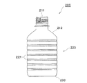
一方、図11に示すプラスチック製容器200(比較例2)は、口部211と、肩部212と、胴部220と、底部230とを備え、胴部220には、水平方向の補強溝221が上下方向に複数(7箇所)形成されている。このプラスチック製容器200(比較例2)において、胴部220に圧力吸収パネルが設けられていない点が本実施の形態によるプラスチック製容器10とは異なっている。
(Comparative Example 2)
On the other hand, the plastic container 200 (Comparative Example 2) shown in FIG. 11 includes a
このようなプラスチック製容器200は、上述したプラスチック製容器100よりも座屈強度や側壁強度に優れるが、容器内の減圧や増圧に十分対応する手段を持たないため、減圧や増圧により容器が歪な形に変形するおそれがある。
Such a
これに対して本実施の形態に係るプラスチック製容器10は、圧力吸収パネル40に凸状リブ41及び凹状リブ42が設けられていることにより、減圧吸収機能に優れ、座屈強度が強く、かつ側壁強度も強めることができる。
On the other hand, the
10 プラスチック製容器
11 口部
12 肩部
20 胴部
20a 外周面
21 垂直支柱
22 上部水平支柱
23 下部水平支柱
24 上部補強溝
25 下部補強溝
30 底部
40 圧力吸収パネル
41 凸状リブ
41a 平坦面
42 凹状リブ
42a 平坦面
43 接続面
44 傾斜面
DESCRIPTION OF
Claims (9)
口部と、
肩部と、
胴部と、
底部とを備え、
胴部は、円周方向に沿って配置された複数の圧力吸収パネルと、各圧力吸収パネル間に配置され、垂直方向に延びる垂直支柱とを有し、
各圧力吸収パネル内に、外方に突出する複数の凸状リブと、各凸状リブ間に位置する凹状リブとが設けられ、凸状リブ及び凹状リブの周囲を取り囲むように、胴部の外周面に対して傾斜する接続面が設けられ、
各凸状リブおよび各凹状リブは、それぞれ接続面のうち圧力吸収パネルの一端側に位置する箇所から接続面のうち圧力吸収パネルの他端側に位置する箇所までV字状に延びて隣り合う垂直支柱同士を連結し、
凸状リブは、その表面に平坦面を有し、凹状リブは、その内部に平坦面を有することを特徴とするプラスチック製容器。 In plastic containers,
The mouth,
Shoulder and
The torso,
With a bottom,
The trunk includes a plurality of pressure absorbing panels arranged along the circumferential direction, and vertical struts arranged between the pressure absorbing panels and extending in the vertical direction,
Each pressure absorbing panel is provided with a plurality of convex ribs projecting outward and concave ribs positioned between the convex ribs, and surrounding the circumference of the convex ribs and the concave ribs. A connecting surface that is inclined with respect to the outer peripheral surface is provided,
Each convex rib and each concave rib extend adjacent to each other in a V shape from a position located on one end side of the pressure absorption panel of the connection surface to a position located on the other end side of the pressure absorption panel of the connection surface. Connect the vertical struts ,
Convex rib has a flat surface on the surface thereof, concave ribs, plastic containers, characterized in Rukoto which having a flat surface therein.
Priority Applications (1)
| Application Number | Priority Date | Filing Date | Title |
|---|---|---|---|
| JP2012250296A JP6236770B2 (en) | 2012-11-14 | 2012-11-14 | Plastic container |
Applications Claiming Priority (1)
| Application Number | Priority Date | Filing Date | Title |
|---|---|---|---|
| JP2012250296A JP6236770B2 (en) | 2012-11-14 | 2012-11-14 | Plastic container |
Publications (2)
| Publication Number | Publication Date |
|---|---|
| JP2014097823A JP2014097823A (en) | 2014-05-29 |
| JP6236770B2 true JP6236770B2 (en) | 2017-11-29 |
Family
ID=50940216
Family Applications (1)
| Application Number | Title | Priority Date | Filing Date |
|---|---|---|---|
| JP2012250296A Active JP6236770B2 (en) | 2012-11-14 | 2012-11-14 | Plastic container |
Country Status (1)
| Country | Link |
|---|---|
| JP (1) | JP6236770B2 (en) |
Families Citing this family (1)
| Publication number | Priority date | Publication date | Assignee | Title |
|---|---|---|---|---|
| JP6707884B2 (en) * | 2016-02-05 | 2020-06-10 | 東洋製罐株式会社 | Synthetic resin container |
Family Cites Families (12)
| Publication number | Priority date | Publication date | Assignee | Title |
|---|---|---|---|---|
| JPH0712243Y2 (en) * | 1987-11-30 | 1995-03-22 | 株式会社吉野工業所 | Container with reinforcing ribs |
| JPH043910U (en) * | 1990-04-23 | 1992-01-14 | ||
| JPH0410010U (en) * | 1990-05-16 | 1992-01-28 | ||
| JP3881154B2 (en) * | 2000-04-28 | 2007-02-14 | 株式会社吉野工業所 | Bottle-shaped synthetic resin container suitable for filling high temperature contents |
| JP3942803B2 (en) * | 2000-05-17 | 2007-07-11 | 株式会社吉野工業所 | Bottle vacuum absorption panel |
| CN100586804C (en) * | 2003-11-26 | 2010-02-03 | 株式会社吉野工业所 | Synthetic resin heat-resistant bottle type container |
| JP4696717B2 (en) * | 2005-06-23 | 2011-06-08 | 東洋製罐株式会社 | Plastic container |
| JP4894034B2 (en) * | 2005-10-31 | 2012-03-07 | 株式会社吉野工業所 | Square resin container |
| JP4935058B2 (en) * | 2005-11-21 | 2012-05-23 | 東洋製罐株式会社 | Plastic container |
| JP2007320612A (en) * | 2006-05-31 | 2007-12-13 | Toyo Seikan Kaisha Ltd | Container made of synthetic resin |
| JP4840652B2 (en) * | 2006-07-31 | 2011-12-21 | 株式会社吉野工業所 | Synthetic resin housing |
| JP5024168B2 (en) * | 2008-03-25 | 2012-09-12 | 東洋製罐株式会社 | Plastic container |
-
2012
- 2012-11-14 JP JP2012250296A patent/JP6236770B2/en active Active
Also Published As
| Publication number | Publication date |
|---|---|
| JP2014097823A (en) | 2014-05-29 |
Similar Documents
| Publication | Publication Date | Title |
|---|---|---|
| US9969520B2 (en) | Vacuum resistant ribs for lightweight base technology containers | |
| WO2011007734A1 (en) | Plastic bottle | |
| JP6531401B2 (en) | Plastic bottle | |
| JP6160895B2 (en) | Plastic bottle | |
| JP6421581B2 (en) | Plastic bottle | |
| JP6146640B2 (en) | Plastic container | |
| JP6236770B2 (en) | Plastic container | |
| JP6236769B2 (en) | Plastic container | |
| JP7180254B2 (en) | plastic bottle | |
| JP5102097B2 (en) | Resin beverage container | |
| JP6146641B2 (en) | Plastic container | |
| JP5556083B2 (en) | Plastic bottle | |
| JP5428604B2 (en) | Plastic bottle | |
| JP5424100B2 (en) | Pressure resistant bottle | |
| JP2016132501A (en) | Plastic bottle | |
| JP2014069840A (en) | Plastic bottle | |
| JP6131627B2 (en) | Plastic bottle | |
| JP5370835B2 (en) | Pressure resistant bottle | |
| JP6135173B2 (en) | Plastic bottle | |
| JP6060595B2 (en) | Plastic bottle containers | |
| JP6135172B2 (en) | Plastic bottle | |
| JP7410449B2 (en) | plastic bottle | |
| JP7173433B2 (en) | plastic bottle | |
| JP6395997B2 (en) | Plastic bottle | |
| JP7085106B2 (en) | Plastic bottle |
Legal Events
| Date | Code | Title | Description |
|---|---|---|---|
| A621 | Written request for application examination |
Free format text: JAPANESE INTERMEDIATE CODE: A621 Effective date: 20150930 |
|
| A977 | Report on retrieval |
Free format text: JAPANESE INTERMEDIATE CODE: A971007 Effective date: 20160613 |
|
| A131 | Notification of reasons for refusal |
Free format text: JAPANESE INTERMEDIATE CODE: A131 Effective date: 20160621 |
|
| A521 | Written amendment |
Free format text: JAPANESE INTERMEDIATE CODE: A523 Effective date: 20160819 |
|
| A131 | Notification of reasons for refusal |
Free format text: JAPANESE INTERMEDIATE CODE: A131 Effective date: 20170421 |
|
| A521 | Written amendment |
Free format text: JAPANESE INTERMEDIATE CODE: A523 Effective date: 20170616 |
|
| TRDD | Decision of grant or rejection written | ||
| A01 | Written decision to grant a patent or to grant a registration (utility model) |
Free format text: JAPANESE INTERMEDIATE CODE: A01 Effective date: 20171003 |
|
| A61 | First payment of annual fees (during grant procedure) |
Free format text: JAPANESE INTERMEDIATE CODE: A61 Effective date: 20171016 |
|
| R150 | Certificate of patent or registration of utility model |
Ref document number: 6236770 Country of ref document: JP Free format text: JAPANESE INTERMEDIATE CODE: R150 |