JP6236066B2 - Tool for producing a casting core for a turbine engine blade and method for producing the same - Google Patents
Tool for producing a casting core for a turbine engine blade and method for producing the same Download PDFInfo
- Publication number
- JP6236066B2 JP6236066B2 JP2015510863A JP2015510863A JP6236066B2 JP 6236066 B2 JP6236066 B2 JP 6236066B2 JP 2015510863 A JP2015510863 A JP 2015510863A JP 2015510863 A JP2015510863 A JP 2015510863A JP 6236066 B2 JP6236066 B2 JP 6236066B2
- Authority
- JP
- Japan
- Prior art keywords
- rod
- core
- mold
- tooling
- tooling according
- Prior art date
- Legal status (The legal status is an assumption and is not a legal conclusion. Google has not performed a legal analysis and makes no representation as to the accuracy of the status listed.)
- Active
Links
- 238000005266 casting Methods 0.000 title claims description 16
- 238000004519 manufacturing process Methods 0.000 title claims description 6
- 239000000919 ceramic Substances 0.000 claims description 22
- 125000006850 spacer group Chemical group 0.000 claims description 20
- 230000013011 mating Effects 0.000 claims description 18
- 238000007373 indentation Methods 0.000 claims description 15
- 238000001816 cooling Methods 0.000 claims description 9
- 239000012530 fluid Substances 0.000 claims description 5
- 229910010293 ceramic material Inorganic materials 0.000 claims description 3
- 239000000945 filler Substances 0.000 claims description 3
- 238000000034 method Methods 0.000 claims description 3
- 239000011162 core material Substances 0.000 description 69
- 230000000295 complement effect Effects 0.000 description 8
- 238000000465 moulding Methods 0.000 description 4
- 238000004891 communication Methods 0.000 description 3
- 229910045601 alloy Inorganic materials 0.000 description 2
- 239000000956 alloy Substances 0.000 description 2
- 238000002347 injection Methods 0.000 description 2
- 239000007924 injection Substances 0.000 description 2
- 239000000463 material Substances 0.000 description 2
- 239000002184 metal Substances 0.000 description 2
- 229910001092 metal group alloy Inorganic materials 0.000 description 2
- 239000000203 mixture Substances 0.000 description 2
- 239000000243 solution Substances 0.000 description 2
- 239000011230 binding agent Substances 0.000 description 1
- 230000003628 erosive effect Effects 0.000 description 1
- 238000003780 insertion Methods 0.000 description 1
- 230000037431 insertion Effects 0.000 description 1
- 238000007711 solidification Methods 0.000 description 1
- 230000008023 solidification Effects 0.000 description 1
- 239000000126 substance Substances 0.000 description 1
Images


Classifications
-
- B—PERFORMING OPERATIONS; TRANSPORTING
- B22—CASTING; POWDER METALLURGY
- B22C—FOUNDRY MOULDING
- B22C13/00—Moulding machines for making moulds or cores of particular shapes
- B22C13/12—Moulding machines for making moulds or cores of particular shapes for cores
-
- B—PERFORMING OPERATIONS; TRANSPORTING
- B22—CASTING; POWDER METALLURGY
- B22C—FOUNDRY MOULDING
- B22C9/00—Moulds or cores; Moulding processes
- B22C9/10—Cores; Manufacture or installation of cores
- B22C9/103—Multipart cores
-
- B—PERFORMING OPERATIONS; TRANSPORTING
- B22—CASTING; POWDER METALLURGY
- B22C—FOUNDRY MOULDING
- B22C21/00—Flasks; Accessories therefor
- B22C21/12—Accessories
- B22C21/14—Accessories for reinforcing or securing moulding materials or cores, e.g. gaggers, chaplets, pins, bars
-
- B—PERFORMING OPERATIONS; TRANSPORTING
- B22—CASTING; POWDER METALLURGY
- B22C—FOUNDRY MOULDING
- B22C9/00—Moulds or cores; Moulding processes
- B22C9/10—Cores; Manufacture or installation of cores
-
- B—PERFORMING OPERATIONS; TRANSPORTING
- B22—CASTING; POWDER METALLURGY
- B22C—FOUNDRY MOULDING
- B22C9/00—Moulds or cores; Moulding processes
- B22C9/18—Finishing
-
- B—PERFORMING OPERATIONS; TRANSPORTING
- B22—CASTING; POWDER METALLURGY
- B22C—FOUNDRY MOULDING
- B22C9/00—Moulds or cores; Moulding processes
- B22C9/22—Moulds for peculiarly-shaped castings
- B22C9/24—Moulds for peculiarly-shaped castings for hollow articles
-
- F—MECHANICAL ENGINEERING; LIGHTING; HEATING; WEAPONS; BLASTING
- F01—MACHINES OR ENGINES IN GENERAL; ENGINE PLANTS IN GENERAL; STEAM ENGINES
- F01D—NON-POSITIVE DISPLACEMENT MACHINES OR ENGINES, e.g. STEAM TURBINES
- F01D5/00—Blades; Blade-carrying members; Heating, heat-insulating, cooling or antivibration means on the blades or the members
- F01D5/12—Blades
- F01D5/14—Form or construction
- F01D5/18—Hollow blades, i.e. blades with cooling or heating channels or cavities; Heating, heat-insulating or cooling means on blades
-
- F—MECHANICAL ENGINEERING; LIGHTING; HEATING; WEAPONS; BLASTING
- F01—MACHINES OR ENGINES IN GENERAL; ENGINE PLANTS IN GENERAL; STEAM ENGINES
- F01D—NON-POSITIVE DISPLACEMENT MACHINES OR ENGINES, e.g. STEAM TURBINES
- F01D5/00—Blades; Blade-carrying members; Heating, heat-insulating, cooling or antivibration means on the blades or the members
- F01D5/12—Blades
- F01D5/14—Form or construction
- F01D5/20—Specially-shaped blade tips to seal space between tips and stator
-
- F—MECHANICAL ENGINEERING; LIGHTING; HEATING; WEAPONS; BLASTING
- F05—INDEXING SCHEMES RELATING TO ENGINES OR PUMPS IN VARIOUS SUBCLASSES OF CLASSES F01-F04
- F05D—INDEXING SCHEME FOR ASPECTS RELATING TO NON-POSITIVE-DISPLACEMENT MACHINES OR ENGINES, GAS-TURBINES OR JET-PROPULSION PLANTS
- F05D2230/00—Manufacture
- F05D2230/20—Manufacture essentially without removing material
- F05D2230/21—Manufacture essentially without removing material by casting
Description
本発明は、タービンエンジンブレードに冷却回路を作製するための鋳物用中子を製作するためのツーリングに関する。 The present invention relates to tooling for producing a casting core for producing a cooling circuit in a turbine engine blade.
タービンエンジンブレード、および特にタービンエンジンのタービンホイール用のブレードは、ブレード根元に形成されるオリフィスを介して空気が供給される冷却回路を含み、これらのオリフィスは、ブレードのエーロフォイルの先端でバスタブに連通するブレードの内部キャビティに通じている。バスタブは、ブレードの先端で凹部によって形成され、バスタブ底壁によってブレードの内部キャビティから分離され、これは、前記底壁を通過するオリフィスを介して内部キャビティと流体流連通している。作動中、空気は、ブレード根元のオリフィス内に侵入し、ブレードの内部キャビティに沿って流れ、次いで、一部は上述のオリフィスを介してバスタブに、また一部はブレードのエーロフォイルの空気出口オリフィスを介してタービンを通して環状通路に排出される。 Turbine engine blades, and particularly blades for turbine engine turbine wheels, include cooling circuits that are supplied with air through orifices formed in the blade roots, which orifices in the bathtub at the tip of the blade airfoil. It communicates with the internal cavity of the communicating blade. The bathtub is formed by a recess at the tip of the blade and is separated from the internal cavity of the blade by the bathtub bottom wall, which is in fluid flow communication with the internal cavity through an orifice passing through the bottom wall. In operation, air enters the blade root orifice and flows along the blade's internal cavity, then partly into the bathtub through the above-mentioned orifice and partly the airfoil air outlet orifice of the blade And is discharged to the annular passage through the turbine.
このタイプのブレードの冷却回路は、特にバスタブと、ブレードの内部キャビティと、バスタブと内部キャビティとの間で流体流連通を提供するバスタブ底壁のオリフィスとを含む。 This type of blade cooling circuit includes in particular a bathtub, an internal cavity of the blade, and an orifice in the bathtub bottom wall that provides fluid flow communication between the bathtub and the internal cavity.
この冷却回路は、形状が複雑であり、これは、通常、ブレードを作製するために溶融金属が鋳造される金型に挿入される鋳物用中子によって得られる。 This cooling circuit is complex in shape and is usually obtained by a casting core that is inserted into a mold in which molten metal is cast to produce a blade.
文献欧州特許第1661642号明細書、欧州特許第1754555号明細書、および欧州特許第1980343号明細書は、このタイプの中子を説明している。 The documents EP 1 616 642, EP 1 754 555 and EP 198 343 describe this type of core.
中子は、通常、セラミックフィラーおよびポリマー系バインダーを含むペーストから作製され、そのペーストは、ツーリングの金型に注入され、次いで中子を固化させるために加熱される。 The core is usually made from a paste containing a ceramic filler and a polymeric binder, which paste is poured into a tooling mold and then heated to solidify the core.
先行技術においては、ツーリングの金型は、ブレードのバスタブを形成することになる中子の第1の部分のための、およびブレードの1つまたは複数のそれぞれの内部キャビティを形成することになる1つまたは複数の他の部分のための、へこみを含む。 In the prior art, the tooling mold will form one or more respective internal cavities for the first part of the core that will form the bathtub of the blade and 1 Indentation for one or more other parts.
金型は、へこみの第1の部分を中子のそのまたは他の部分から分離する壁を含み、この壁は、その第1の部分とその他の部分との間の中子のスペースを画定する働きをする。ブレードの製作中に、溶融金属が、ブレードの上述のバスタブ底壁を形成するために中子のこのスペース内に侵入する。 The mold includes a wall that separates the first portion of the dent from that or other portion of the core, the wall defining a space in the core between the first portion and the other portion. Work. During the manufacture of the blade, molten metal penetrates into this space of the core to form the aforementioned bathtub bottom wall of the blade.
上記で説明したように、このバスタブ底壁は、オリフィスによって貫通される。これらのオリフィスは、中子を製作する前に金型に位置決めされ、かつこれが製作された後には中子の一体的部分を形成するセラミックロッドを使って鋳造で得られる。 As explained above, this bathtub bottom wall is penetrated by an orifice. These orifices are obtained by casting using a ceramic rod that is positioned in the mold before the core is manufactured and that forms an integral part of the core after it is manufactured.
各セラミックロッドは、通常、中子の第1の部分を上述の他の部分のうちの1つに接続する(欧州特許第1754555号明細書)。 Each ceramic rod usually connects the first part of the core to one of the other parts mentioned above (EP 1754555).
先行技術においては、中子を製作するための金型は、各ロッドの端部に当接しており、かつ/またはそれを埋め込むための手段を含む。それらの手段のうちの1つは、金型の上述の壁に形成され、他の手段は、金型のもう1つの部分に形成され、それは、中子の第1の部分のためのへこみに対して上述の壁と反対側にある。したがって、各ロッドは、金型の第1の部分のへこみを通過する。 In the prior art, the mold for making the core abuts the end of each rod and / or includes means for embedding it. One of those means is formed in the above-mentioned wall of the mold and the other means is formed in the other part of the mold, which is in the recess for the first part of the core. It is on the opposite side to the above-mentioned wall. Thus, each rod passes through a recess in the first part of the mold.
特に、バスタブ底部のオリフィスの直径は、中子のセラミックロッドの直径に依存する。これらのオリフィスの直径を減少させるために、ロッドの直径を減少させることができる。それにもかかわらず、小さな直径の(たとえば、約0.6ミリメートル(mm)の)ロッドはペーストが金型に注入されている間に比較的壊れやすく、頻繁に破壊することが分かっており、それによって中子は廃棄されるようになる。 In particular, the diameter of the bathtub bottom orifice depends on the diameter of the core ceramic rod. In order to reduce the diameter of these orifices, the diameter of the rods can be reduced. Nevertheless, small diameter rods (eg about 0.6 millimeters (mm)) have been found to be relatively fragile and frequently break while the paste is being injected into the mold, As a result, the core is discarded.
本発明の特定の目的は、簡単で、効果的でかつ費用のかからないこの問題の解決策を提供することである。 A particular object of the present invention is to provide a solution to this problem that is simple, effective and inexpensive.
このために、本発明は、タービンエンジンブレードに冷却回路を作製するための鋳物用中子を製作するためのツーリングにして、中子が、ブレードのバスタブを画定するための第1の部分と、ブレードに内部キャビティを画定するための少なくとも1つの他の部分と、第1の部分とそのまたは各他の部分との間に延在し、バスタブとブレードの対応する内部キャビティとの間で流体を通過させるための手段を画定することになる少なくとも1つのロッドとを備え、ツーリングが、ペーストを注入し、かつ第1の部分のための、および中子のそのまたは各他の部分のためのへこみを有するための金型と、そのまたは各ロッドの端部に当接しており、かつ/またはそれを埋め込むための手段とを備え、これらの手段のうちの1つが、中子の第1の部分のためのへこみと中子のそのまたは各他の部分のためのへこみとの間の金型の壁に形成されるツーリングであって、そのまたは各ロッドの実質的な中央部分を支持するように中子の第1の部分のためのへこみに支持手段を含むことを特徴とする、ツーリングを提供する。 To this end, the present invention is a tooling for producing a casting core for producing a cooling circuit on a turbine engine blade, wherein the core defines a first portion for defining a bathtub of the blade; At least one other portion for defining an internal cavity in the blade, and extending between the first portion and its or each other portion to allow fluid to flow between the bathtub and the corresponding internal cavity of the blade At least one rod that will define means for passing through, the tooling injecting the paste, and a dent for the first part and for that or each other part of the core And a means for abutting and / or embedding the or each rod end, one of these means being a first of the core Tooling formed in the mold wall between the indentation for the minute and the indentation for that or each other part of the core, so as to support the substantial central part of that or each rod A tooling is provided, characterized in that it includes support means in the recess for the first part of the core.
本発明によれば、そのまたは各ロッドの中央部分は、ペーストが金型に注入されている間に座屈を最も受けるロッドの部分であるが、ペーストを注入している間に加えられる力の影響の下でそれらが変形し破壊することを防止するように、適切な位置にそのまたは各ロッドを保持するための手段によって支持される。本発明により、ロッド(複数のロッド)が0.8mmよりも小さい、たとえば約0.6mmの比較的小さな直径から成るタービンエンジンブレード用の鋳物用中子を作製することができる。 According to the present invention, the central part of that or each rod is the part of the rod that is most buckled while the paste is being injected into the mold, but the force applied during the injection of the paste. Supported by means for holding the or each rod in place to prevent them from deforming and breaking under influence. The present invention makes it possible to produce a casting core for a turbine engine blade in which the rod (s) is of a relatively small diameter of less than 0.8 mm, for example about 0.6 mm.
ロッドを支持するための支持手段は、他のロッドを支持するための支持手段から独立している。ロッドを支持するための手段は、互いから間隔を置いて設けられることができ、ロッドを支持するための手段は、ロッド用の当接手段および/または係合手段から中途に位置していてもよい。 The support means for supporting the rod is independent of the support means for supporting the other rod. The means for supporting the rod can be spaced from each other, and the means for supporting the rod can be located midway from the abutment means and / or the engagement means for the rod. Good.
例示として、支持手段は、中子の第1の部分のためのへこみの底部から突出する少なくとも1つの突出部材を備え、この部材は、たとえば、形状が実質的に半卵形である。 Illustratively, the support means comprises at least one projecting member projecting from the bottom of the recess for the first part of the core, which member is, for example, substantially hemispherical in shape.
そのまたは各部材は、ロッドの中央部分を受け入れるためにその先端にノッチを含むことができる。 The or each member can include a notch at its tip to receive the central portion of the rod.
ノッチは、実質的にL字形の断面から成ることができ、対応するロッドの長手方向軸線に実質的に平行であることになる2つの平面状の交差する面を有することが好ましい。ロッドは、ロッドの軸線に実質的に平行である当接線を介して面の各々に当接していることになる。 The notches can be substantially L-shaped in cross section and preferably have two planar intersecting surfaces that will be substantially parallel to the longitudinal axis of the corresponding rod. The rod is in contact with each of the faces via contact lines that are substantially parallel to the axis of the rod.
また、ノッチは、実質的にU字形またはC字形である断面を有することができ、互いに対して、および対応するロッドの長手方向軸線に対して実質的に平行である2つの平面状の側面を備える。 The notches can also have a cross-section that is substantially U-shaped or C-shaped, with two planar sides that are substantially parallel to each other and to the longitudinal axis of the corresponding rod. Prepare.
ノッチが実質的にL字形である場合には、ツーリングへのペーストの注入中に、ペーストがロッドに横方向の力を加えることができ、次にこのロッドは移動し破壊する場合があることが分かっている。これは、特に、ロッドがその支持部材によって完全に支持されるとは限らない側面から方向付けられるロッドへの力をペーストが加える場合に当てはまる。 If the notch is substantially L-shaped, the paste can apply a lateral force to the rod during the injection of the paste into the tooling, which can then move and break. I know. This is especially true when the paste applies a force on the rod that is directed from the side, where the rod is not fully supported by its support member.
したがって、各部材のノッチのU字形またはC字形の断面は、ロッドの中央部分を受け入れ、したがって、これは、部材によって両側で支持される。ツーリングに注入されるペーストがロッドに横方向の力を加える場合には、ロッドは、部材によって適切な位置に保持され、移動されまたは破壊され得ない。この特定のU字形またはC字形の断面は、L字形の断面よりも良好な支持を提供する。 Thus, the U-shaped or C-shaped cross section of each member's notch receives the central portion of the rod, and therefore it is supported on both sides by the member. If the paste injected into the tooling exerts a lateral force on the rod, the rod is held in place by the member and cannot be moved or destroyed. This particular U-shaped or C-shaped cross section provides better support than the L-shaped cross section.
ノッチの側面の各々は、特にロッドをノッチに挿入することを容易にするように、凸状の丸み付き縁部を介して部材の上面に接続される。 Each of the side surfaces of the notch is connected to the top surface of the member via a convex rounded edge, in particular to facilitate the insertion of the rod into the notch.
したがって、ロッドは、ロッドの軸線に実質的に平行であるそれぞれの当接線を介してこれらの側面の各々に当接しているようにさせられる。変形においては、組立位置において、ロッドは、面のうちの1つから、またはそれらの両方から(0.1mmよりも小さい)小さな距離を置いておくことができる。 Thus, the rod is caused to abut each of these sides via respective abutment lines that are substantially parallel to the axis of the rod. In a variant, in the assembled position, the rod can be kept a small distance (less than 0.1 mm) from one of the faces or both.
ノッチの面のうちの1つは、ペーストが金型に注入される方向に対して、特に中子の第1の部分のためのそのへこみにおいて実質的に直角であってもよい。金型へのペーストの注入中に、ロッドは、ペーストの流れに対向し、かつロッドが適切な位置に十分に保持されることを確保するこの面に当接している。 One of the faces of the notch may be substantially perpendicular to the direction in which the paste is poured into the mold, particularly in its indentation for the first part of the core. During the pouring of the paste into the mold, the rod bears against this surface that opposes the paste flow and ensures that the rod is sufficiently held in place.
ロッドがU字形またはC字形である断面を有する場合には、金型へのペーストの注入中に、ロッドが、ペーストの流れに対向し、かつロッドが適切な位置に十分に保持されることを確保するこれらの面に当接しているように、側面は、ペーストが金型に注入される方向に対して実質的に直角であり得る。 If the rod has a U-shaped or C-shaped cross-section, during the pouring of the paste into the mold, the rod will face the paste flow and be sufficiently held in place The side surfaces can be substantially perpendicular to the direction in which the paste is poured into the mold so that they abut against these securing surfaces.
そのまたは各部材は、金型と一体に形成されることができ、または、これは、金型と分離してそれに固締され得る。 The or each member can be formed integrally with the mold, or it can be separated from the mold and secured thereto.
また、ツーリングは、そのまたは各ロッドの中央部分を支持するための支持手段を同様に含む相手金型を含むことができる。 The tooling can also include a mating die that also includes support means for supporting the central portion of the or each rod.
有利なことに、本発明のツーリングは、そのまたは各ロッドが対応する部材のノッチの中で移動することを防止するための手段を含む相手金型を含み、これらの手段は、相手金型のへこみの中に突出して形成される少なくとも1つのスペーサを含み、その先端において、ノッチの頂部部分に係合するための、および/またはそのノッチに受け入れられるロッドの部分に当接しているためのフィンガを含む。 Advantageously, the tooling of the present invention includes a mating die that includes means for preventing the or each rod from moving within the notch of the corresponding member, and these means include: A finger including at least one spacer formed projecting into the indentation, for engaging the top portion of the notch at the tip and / or abutting the portion of the rod received in the notch including.
金型および相手金型が組立位置にある場合には、そのまたは各スペーサは、特にペーストがツーリングに注入されており、かつこれをノッチから脱落させる傾向のあるロッドへの力(たとえば、上向きの力)を加えている間に、ロッドが部材のノッチを離れることを防止するように対応する部材に面する位置を占めることになる。次いで、ロッドは、長手方向軸線に直角な平面においてロッドのいかなる移動も共に防止する部材によっておよびスペーサによって適切な位置に保持され、それによって、ロッドが破壊するいかなる危険性も制限される。 When the mold and mating mold are in the assembled position, the spacer or each of the spacers has a force on the rod (e.g., upwards), especially where the paste has been injected into the tooling and tends to fall out of the notch During the application of force, the rod will occupy the position facing the corresponding member so as to prevent it from leaving the notch of the member. The rod is then held in place by a member that prevents any movement of the rod together in a plane perpendicular to the longitudinal axis and by a spacer, thereby limiting any risk of the rod breaking.
そのまたは各スペーサは、対応する部材の頂部に当接しており、かつそれを位置決めするための手段を含むことが好ましい。 The or each spacer preferably abuts the top of the corresponding member and includes means for positioning it.
金型の部材のうちのいくつかのみが相手金型のスペーサと結合するように、相手金型は、金型の部材の数よりも少ないいくつかのスペーサを含むことができる。 The mating mold can include a number of spacers that are fewer than the number of mold parts, such that only some of the mold members are coupled to the mating mold spacers.
支持手段は、少なくとも3つまたは4つの突出部材を含むことができる。相手金型は、組立位置において、作製されることになる中子の後縁のそばに位置している金型の部材と協働するためのただ1つのスペーサを含むことができる。 The support means may include at least 3 or 4 protruding members. The mating mold may include only one spacer for cooperating with the mold member located near the trailing edge of the core to be fabricated in the assembly position.
また、本発明は、セラミックフィラーを含むペーストをツーリングに注入するステップと、中子を固化させ、取り出すステップとを含む、上記で説明したツーリングを使って鋳物用中子を製作する方法であって、中子を取り出すステップの後に、たとえばセラミック材料でツーリング支持手段によって画定される中子のそのまたは各凹部に充填するステップにある、追加のステップを含むことを特徴とする、方法を提供する。 The present invention is also a method for producing a casting core using the tooling described above, comprising the steps of injecting a paste containing a ceramic filler into the tooling and solidifying and removing the core. A method is provided, characterized in that it comprises an additional step after the step of removing the core, for example in the step of filling the or each recess of the core defined by the tooling support means with ceramic material.
本発明のツーリングを使って作製される中子は、金型の支持手段の存在のため、ブレードのバスタブを画定するためのその第1の部分に少なくとも1つの小さなセットバックまたは凹部を有する。この凹部は、中子の材料に類似した材料で容易に充填される。 The core made using the tooling of the present invention has at least one small setback or recess in its first part for defining the bathtub of the blade due to the presence of the mold support means. This recess is easily filled with a material similar to the core material.
本発明は、非限定的な例としてかつ添付の図面を参照して行われる次の説明を読むと、よりよく理解されることができ、本発明の他の特徴、詳細、および利点がよりはっきりと明らかになる。 The invention will be better understood upon reading the following description, given as a non-limiting example and with reference to the accompanying drawings, where other features, details and advantages of the invention will become clearer It becomes clear.
初めに、タービンエンジン圧縮機またはタービンのロータブレード10を示す図1を参照すると、ロータブレードは、プラットフォーム14によって根元16に接続されるエーロフォイル12を備えている。
Referring initially to FIG. 1 showing a turbine engine compressor or
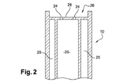
ブレード10は、図2で一部を見ることができる内部冷却回路を含み、回路には、ブレード根元16のオリフィス18を介して空気が供給される。これらのオリフィスは、ブレード冷却空気が流れるブレードの内部キャビティ20に通じている。次いで、この空気は、エーロフォイル12の後縁のオリフィス22を介して、およびエーロフォイルの先端のオリフィス24を介して排出される。
The
エーロフォイルの先端のオリフィス24は、エーロフォイル12の先端のセットバックによって形成され、かつバスタブ壁28の底部によって内部キャビティ20から分離されるバスタブ26に通じており、その中に、前記のオリフィス24が形成される。
The
ブレード10の冷却回路は、その中に溶融金属合金が鋳造されるセラミックシェルモールドで組み立てられる中子を使って鋳造で得られる。ブレードの固化および取り出し後に、中子は、たとえば薬品浸食によって取り除かれる。
The cooling circuit of the
図3は、このタイプの中子30を非常に概略的な方法で示しており、中子30は、ブレードのバスタブ26を形成するための第1の部分32と、ブレードのそれぞれの内部キャビティ20を形成するための他の部分34と、各々が第1の部分32を他の部分34のうちの1つに接続するセラミックロッド36とを備える。
FIG. 3 shows this type of
中子30の第1の部分32は、形成されることになるバスタブ26の形状および寸法に相補的な形状および寸法から成り、同様に、他の部分34は、形成されることになるキャビティ20の形状および寸法に相補的な形状および寸法から成る。
The
セラミックロッド36は、2つの機能、すなわち、中子30のさまざまな部分を機械的に相互に接続させること、および所定の位置にかつ所定の間隔でこれらの部分を保持することを行なう。図3で理解できるように、中子の第1の部分32は、中子の第1の部分と他の部分との間に延在するロッド部分36の長さに依存する厚さのスペース38によって他の部分34から分離される。
The
溶融合金をセラミックシェルモールドに鋳造しながら、合金の部分は、バスタブの底壁28を形成するために中子30のスペース38に侵入する必要があり、これは、スペース38の厚さによって決定される厚さから成る。
While casting the molten alloy into a ceramic shell mold, the portion of the alloy must enter the
中子30のセラミックロッド36は、壁28のオリフィス24を形成するためのものであり、これらのオリフィス24は、ブレードのバスタブ26と内部キャビティ20との間に流体流連通を提供する。特に、これらのオリフィス24の直径は、中子30のセラミックロッド36の直径に依存する。
The
セラミックロッド36は、ペーストを金型に注入する前に中子製作ツーリングの金型に組み立てられる。先行技術においては、金型は、第1の部分32のための第1のへこみと、中子30の他の部分34のための第2のへこみとを備え、これらのへこみは、中子の上述のスペース38を形成することになる壁によって互いから分離される。
The
セラミックロッド36は、第1のへこみを全部通過するように金型に組み立てられ、各ロッドの端部は、金型のソケットに埋め込まれ、ロッドの反対側の端部は、金型の第2のへこみの中に延在し、金型の上述の壁に当接している。
The
上記で説明したように、セラミックロッド36、特に小さな直径の(たとえば、0.6mm程度の)ロッドは、ペーストが金型に注入されている間に破壊する傾向があり、それによって中子が廃棄される必要があることが分かっている。
As explained above,
本発明は、ツーリングの金型に組み立てられるセラミックロッドの中央部分を支持するための手段によってその問題の解決策を提供している。 The present invention provides a solution to that problem by means for supporting the central part of the ceramic rod assembled in the tooling mold.
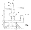
図4および図5は、本発明のツーリングの実施形態を示しており、ツーリングは、中子30の第1の部分32のための第1のへこみ42と、中子の他の部分34のための第2のへこみ44とを有する金型40を備え、これらのへこみ42、44は、中子の上述のスペース38の少なくとも一部を形成することになる壁46によって互いから分離される。
4 and 5 show the tooling embodiment of the present invention, which is for the
ただ1つのセラミックロッド36が、図4および図5に示されており、このロッドは、金型のソケット50に埋め込まれる端部48と、金型の第2のへこみ44の中に延在し、かつ金型の壁46に当接している反対側の端部52とを有する。
Only one
金型の壁46は、ロッド36の一部の断面に実質的に相補的であるU字形C字形の断面のノッチ54を含み、そのロッドは、示される実施例では円筒形である。同様に、金型40のソケット50は、ロッド36の形状に実質的に形状が相補的である。これにより、ペーストが金型40に注入されている間にペーストが、ロッド36と、ノッチ54およびソケット50の壁との間を通過することが防止される。
The
本発明のツーリングは、中子30の第1の部分32のための第1のへこみと、中子の他の部分34のための第2のへこみとを同様に備える(図示せず)相手金型を含むことができ、これらのへこみは、中子の上述のスペース38を形成することになる壁によって互いから分離される。相手金型のこの壁は、金型の壁46の自由縁の形状に相補的な形状の自由縁を有し、それによって、これらの壁は、ツーリングが組み立てられると互いに位置合わせされて、一方を他方に係合する。図5で理解できるように、壁46は、壁がアセンブリに適切に位置決めされることを確保するために、相手金型の壁の相補手段を有する形状を相互に接続させることによって協働するための突出手段56を含むことができる。
The tooling of the present invention also comprises a first dent for the
図4および図5で理解できるように、ロッド36の中央部分は、金型40の第1のへこみ42を通って延在する。本発明によれば、支持手段58が、ロッド36の中央部分を支持するために、かつペーストが金型に注入されている間にロッドのいかなる変形も制限するように適切な位置にこれを保持するためにこのへこみ42に設けられる。
As can be seen in FIGS. 4 and 5, the central portion of the
示される実施例においては、ロッドの支持手段は、金型の第1のへこみ42の底部から突出する突出部材58を備え、この部材は、金型のソケット50とノッチ54との間で実質的に中間点に位置している。
In the embodiment shown, the rod support means comprises a projecting
示される実施例の場合のように、この部材58は、金型40と分離されそれに固締されることができ、でなければ金型と一体に形成されることができる。これは、金型と同じ材料で、すなわち金属合金で作製され得る。
As in the embodiment shown, this
この実施例においては、部材58は、半卵形の形状から成り、その頂部において、これは、ロッド36に係合するためのノッチ60を提示する。図5で理解できるように、このノッチは、L字形の断面からなり、ロッドが金型に組み立てられると、ロッド36の長手方向軸線に実質的に平行に延在する2つの主要なかつ交差する面62および64を有する。面62および64は、約90°の角度を形成する。
In this embodiment,
セラミックロッド36は、ロッドの軸線に実質的に平行である当接線を介して面62および64に達し、それに当接していることになる。
The
ペーストは、金型に注入され、矢印66で示される方向に金型の第1のへこみ42の中に流れることになる。ノッチ60の面64は、実質的にこの方向に直角であり、したがって、ペーストがロッドの周りに流れている間に適切な位置に効果的にロッド36を保持することができ、それによって、ロッドのいかなる変形も制限される。
The paste will be poured into the mold and will flow into the
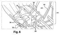
図6は、本発明のもう1つの実施形態を示しており、その中で、ツーリングの金型は、4つのセラミックロッド36を支持するための支持手段58を含み、支持手段は、上記で説明したものと類似しており、互いから独立し間隔を置いて設けられている。
FIG. 6 shows another embodiment of the present invention in which the tooling mold includes support means 58 for supporting four
製作後に、中子30は、中子を製作するために金型に存在する支持手段と同じ数の凹部をその第1の部分32に含む。図4および図5の実施形態においては、中子は1つの凹部を含むが、図6の実施形態においては、中子は4つの凹部を含む。凹部は、形状が支持手段の形状に相補的である。本発明は、これらのソケットが中子の材料の組成に近いことが好ましい組成の充填セラミック材料で充填されるステップを含む方法を提案する。
After fabrication, the
上述のように、図5の金型に注入されるペーストは、ロッド36に対して矢印66の方向と反対の方向に力を加えることができる。部材58のノッチ60の形状のために、ロッドは、面64と反対の側で部材によって支持されず、したがって、ペーストによって加えられる力を受けて移動しまたは破壊し得る。
As described above, the paste injected into the mold of FIG. 5 can apply a force to the
下記で説明される実施形態は、ロッドを受け入れるノッチがU字形またはC字形である断面を提示する支持部材によってこの特定の欠点を改善するものである。 The embodiments described below remedy this particular drawback by a support member presenting a cross-section in which the notch for receiving the rod is U-shaped or C-shaped.
図7は、上記で説明した要素が同じ参照符号で示される第1の実施形態を示している。 FIG. 7 shows a first embodiment in which the elements described above are indicated with the same reference numerals.
部材58は、そのノッチ60’が互いに対しておよびロッド36の長手方向軸線に対して実質的に平行であり、かつノッチの底面62を介して一緒に接続される底端部を有する2つの側面64および65を有するという点で図5に示される部材と異なっている。
The
図7に示される組立位置においては、ロッド36は、面62、64、および65に当接していることになる。それにもかかわらず、部品の製造公差のために、1ミリメートルの10分のいくつか、または100分のいくつかの隙間がロッドと面62、64、および65との間に存在することもあるかもしれない。
In the assembled position shown in FIG. 7, the
したがって、ロッド36は、部材58によって両側に支持され、たとえツーリングに注入されるペーストがロッドの両側でロッドに横方向の力(矢印66および66’)を加えても適切な位置に保持される。
Thus, the
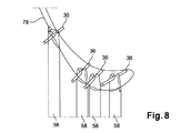
図8〜図10は、ツーリングが4本の棒36を有する本発明の異なる実施形態を示しており、それらの中央部分は、ロッドを受け入れるためのU字形またはC字形の断面のノッチ60’を含む支持部材によって支持される。
FIGS. 8-10 show different embodiments of the invention in which the tooling has four
示される実施例においては、各部材58のノッチ60’の側面64および65は、凸状の丸み付き縁部70によって部材の上面72に接続される(図9および図10)。この実施形態においては、面64および65は、互いに対して少し傾斜しており、面は、それらの底端部においてよりもそれらの頂端部において互いからさらに間隔を置いて設けられる。
In the embodiment shown, the
ツーリングの相手金型(図示せず)は、金型のへこみの中に突出し、かつ組立位置において、金型40の部材58のうちの1つに面することになるスペーサ74を含む。
A tooling mating tool (not shown) includes a
このスペーサ74は、細長い形状から成り、その先端は、部材58のノッチ60’の頂部部分に係合するための、およびロッド36の中央部分に当接しているためのフィンガ76を含む。
The
図10で理解できるように、スペーサ74の先端は、部材58の頂部に実質的に相補的である形状から成り、その部材の上述の上面72に当接している。
As can be seen in FIG. 10, the tip of the
図8〜図10は、形成されることになる中子の断面78を概略的に示している。相手金型のスペーサ74は、中子の後縁のそばに位置している金型の部材58と協働する。スペーサ74により、部材58によって支持されるロッド36が移動しかつその部材のノッチから離脱することが防止される。なぜなら、ツーリングに注入されるペーストは、上向きに向けられ、かつロッドを部材のノッチから脱落させることができるロッドへの力を加え得ることが分かっているからである。ツーリングに注入されるペーストは、この種の力を他の部材58によって支持されるロッド36には加えず、したがって、この他の部材58は、相手金型のスペーサ74と結合する必要はない。
8-10 schematically show a
図面で理解できるように、部材58は、ロッド36がペーストの流れによって受ける力に対して偏向および減衰作用を行なうように、丸みのある外部輪郭を有することが好ましい。
As can be seen in the drawings, the
Claims (19)
Applications Claiming Priority (5)
| Application Number | Priority Date | Filing Date | Title |
|---|---|---|---|
| FR1254350A FR2990367B1 (en) | 2012-05-11 | 2012-05-11 | TOOLING FOR MANUFACTURING A FOUNDRY CORE FOR A TURBOMACHINE BLADE |
| FR1254350 | 2012-05-11 | ||
| FR1258282 | 2012-09-05 | ||
| FR1258282A FR2990368B1 (en) | 2012-05-11 | 2012-09-05 | TOOLING FOR MANUFACTURING A FOUNDRY CORE FOR A TURBOMACHINE BLADE |
| PCT/FR2013/051028 WO2013167847A2 (en) | 2012-05-11 | 2013-05-07 | Tool for manufacturing a foundry core for a turbine engine blade |
Publications (2)
| Publication Number | Publication Date |
|---|---|
| JP2015520677A JP2015520677A (en) | 2015-07-23 |
| JP6236066B2 true JP6236066B2 (en) | 2017-11-22 |
Family
ID=47049311
Family Applications (1)
| Application Number | Title | Priority Date | Filing Date |
|---|---|---|---|
| JP2015510863A Active JP6236066B2 (en) | 2012-05-11 | 2013-05-07 | Tool for producing a casting core for a turbine engine blade and method for producing the same |
Country Status (10)
| Country | Link |
|---|---|
| US (1) | US9505052B2 (en) |
| EP (1) | EP2846948B1 (en) |
| JP (1) | JP6236066B2 (en) |
| CN (1) | CN104271286B (en) |
| BR (1) | BR112014027831B1 (en) |
| CA (1) | CA2872066C (en) |
| FR (2) | FR2990367B1 (en) |
| IN (1) | IN2014DN09458A (en) |
| RU (1) | RU2627084C2 (en) |
| WO (1) | WO2013167847A2 (en) |
Families Citing this family (19)
| Publication number | Priority date | Publication date | Assignee | Title |
|---|---|---|---|---|
| FR3022810B1 (en) * | 2014-06-30 | 2019-09-20 | Safran Aircraft Engines | PROCESS FOR PRODUCING A CORE FOR MOLDING A DAWN |
| CN104338905B (en) * | 2014-10-16 | 2016-06-01 | 沈阳黎明航空发动机(集团)有限责任公司 | A kind of directional solidification blade ceramic core shaping device |
| US10280761B2 (en) * | 2014-10-29 | 2019-05-07 | United Technologies Corporation | Three dimensional airfoil micro-core cooling chamber |
| FR3037829B1 (en) * | 2015-06-29 | 2017-07-21 | Snecma | CORE FOR MOLDING A DAWN WITH OVERLAPPED CAVITIES AND COMPRISING A DEDUSISHING HOLE THROUGH A CAVITY PARTLY |
| FR3047767B1 (en) * | 2016-02-12 | 2019-05-31 | Safran | METHOD FOR FORMING DEDUSTING HOLES FOR TURBINE BLADE AND CERAMIC CORE THEREFOR |
| FR3048374B1 (en) * | 2016-03-01 | 2018-04-06 | Snecma | CORE FOR MOLDING A DAWN WITH SUPERIOR CAVITIES AND COMPRISING A DEDUSTING LINE CONDUCTING A CAVITY FROM PART TO SHARE |
| US20180298765A1 (en) * | 2017-04-14 | 2018-10-18 | General Electric Company | Engine component with replaceable tip element |
| FR3065662B1 (en) | 2017-04-28 | 2020-11-13 | Safran Aircraft Engines | CORE FOR THE MANUFACTURE OF A TURBOMACHINE VANE |
| FR3065661B1 (en) * | 2017-04-28 | 2019-06-14 | Safran Aircraft Engines | CORE FOR THE MANUFACTURE BY LOST WAX MOLDING OF A TURBOMACHINE WATER |
| FR3065660B1 (en) * | 2017-04-28 | 2019-06-14 | Safran Aircraft Engines | ASSEMBLY FOR MANUFACTURING A TURBOMACHINE BLADE |
| FR3070624B1 (en) | 2017-09-06 | 2019-09-13 | Safran Aircraft Engines | CARRIER IN COMPOSITE MATERIAL WITH A STRINGING GEOMETRY |
| KR101955858B1 (en) * | 2018-09-07 | 2019-03-08 | 국방과학연구소 | Flow path forming guide for hollow gas turbine blades and apparatus for manufacturing the flow path forming guide |
| US10913106B2 (en) | 2018-09-14 | 2021-02-09 | Raytheon Technologies Corporation | Cast-in film cooling hole structures |
| US11759850B2 (en) | 2019-05-22 | 2023-09-19 | Siemens Energy Global GmbH & Co. KG | Manufacturing aligned cooling features in a core for casting |
| FR3100143B1 (en) * | 2019-08-30 | 2021-11-12 | Safran | Improved method of manufacturing a ceramic core for the manufacture of turbine engine blades |
| CN111036839B (en) * | 2019-12-31 | 2021-03-23 | 无锡市铭腾模具科技有限公司 | Sand core forming die convenient for demoulding |
| FR3108540B1 (en) * | 2020-03-25 | 2022-04-08 | Safran | Mold for the manufacture of a foundry ceramic core |
| FR3121372B1 (en) * | 2021-03-30 | 2023-03-31 | Safran | System for inserting rods into a ceramic core blank for the manufacture of turbomachine blades |
| FR3126894A1 (en) * | 2021-09-15 | 2023-03-17 | Safran | DEVICE AND METHOD FOR MANUFACTURING A CERAMIC CORE FOR BLADE |
Family Cites Families (14)
| Publication number | Priority date | Publication date | Assignee | Title |
|---|---|---|---|---|
| US4148350A (en) * | 1975-01-28 | 1979-04-10 | Mtu-Motoren Und Turbinen-Union Munchen Gmbh | Method for manufacturing a thermally high-stressed cooled component |
| GB2096523B (en) * | 1981-03-25 | 1986-04-09 | Rolls Royce | Method of making a blade aerofoil for a gas turbine |
| DE3203869C2 (en) * | 1982-02-05 | 1984-05-10 | MTU Motoren- und Turbinen-Union München GmbH, 8000 München | Turbine rotor blades for turbo machines, in particular gas turbine engines |
| US5599166A (en) * | 1994-11-01 | 1997-02-04 | United Technologies Corporation | Core for fabrication of gas turbine engine airfoils |
| US5853044A (en) * | 1996-04-24 | 1998-12-29 | Pcc Airfoils, Inc. | Method of casting an article |
| US5733102A (en) * | 1996-12-17 | 1998-03-31 | General Electric Company | Slot cooled blade tip |
| US6637500B2 (en) * | 2001-10-24 | 2003-10-28 | United Technologies Corporation | Cores for use in precision investment casting |
| US6915840B2 (en) * | 2002-12-17 | 2005-07-12 | General Electric Company | Methods and apparatus for fabricating turbine engine airfoils |
| US6929054B2 (en) * | 2003-12-19 | 2005-08-16 | United Technologies Corporation | Investment casting cores |
| FR2878458B1 (en) | 2004-11-26 | 2008-07-11 | Snecma Moteurs Sa | METHOD FOR MANUFACTURING CERAMIC FOUNDRY CORES FOR TURBOMACHINE BLADES, TOOL FOR IMPLEMENTING THE METHOD |
| FR2889088B1 (en) * | 2005-07-29 | 2008-08-22 | Snecma | CORE FOR BLADE OF TURBOMACHINE |
| FR2914871B1 (en) | 2007-04-11 | 2009-07-10 | Snecma Sa | TOOLS FOR THE MANUFACTURE OF CERAMIC FOUNDRY CORES FOR TURBOMACHINE BLADES |
| FR2957828B1 (en) * | 2010-03-26 | 2012-10-05 | Snecma | EXTRACTION OF ALUMINA RODS USED TO MAINTAIN CORE DURING THE MANUFACTURE OF TURBINE BLADES. |
| CN201855923U (en) * | 2010-10-31 | 2011-06-08 | 东风汽车零部件(集团)有限公司 | Salt core positioning device for internally-cooled oil channel piston |
-
2012
- 2012-05-11 FR FR1254350A patent/FR2990367B1/en active Active
- 2012-09-05 FR FR1258282A patent/FR2990368B1/en active Active
-
2013
- 2013-05-07 EP EP13728448.5A patent/EP2846948B1/en active Active
- 2013-05-07 BR BR112014027831-8A patent/BR112014027831B1/en active IP Right Grant
- 2013-05-07 WO PCT/FR2013/051028 patent/WO2013167847A2/en active Application Filing
- 2013-05-07 CN CN201380024670.0A patent/CN104271286B/en active Active
- 2013-05-07 RU RU2014150082A patent/RU2627084C2/en active
- 2013-05-07 JP JP2015510863A patent/JP6236066B2/en active Active
- 2013-05-07 IN IN9458DEN2014 patent/IN2014DN09458A/en unknown
- 2013-05-07 US US14/400,457 patent/US9505052B2/en active Active
- 2013-05-07 CA CA2872066A patent/CA2872066C/en active Active
Also Published As
| Publication number | Publication date |
|---|---|
| FR2990367A1 (en) | 2013-11-15 |
| CA2872066A1 (en) | 2013-11-14 |
| CN104271286A (en) | 2015-01-07 |
| IN2014DN09458A (en) | 2015-07-17 |
| BR112014027831A2 (en) | 2017-06-27 |
| WO2013167847A2 (en) | 2013-11-14 |
| FR2990368A1 (en) | 2013-11-15 |
| CN104271286B (en) | 2016-09-21 |
| US20150122445A1 (en) | 2015-05-07 |
| EP2846948B1 (en) | 2016-06-15 |
| JP2015520677A (en) | 2015-07-23 |
| FR2990367B1 (en) | 2014-05-16 |
| CA2872066C (en) | 2020-06-23 |
| EP2846948A2 (en) | 2015-03-18 |
| FR2990368B1 (en) | 2014-04-25 |
| BR112014027831B1 (en) | 2019-10-29 |
| US9505052B2 (en) | 2016-11-29 |
| RU2627084C2 (en) | 2017-08-03 |
| WO2013167847A3 (en) | 2014-07-03 |
| RU2014150082A (en) | 2016-07-10 |
Similar Documents
| Publication | Publication Date | Title |
|---|---|---|
| JP6236066B2 (en) | Tool for producing a casting core for a turbine engine blade and method for producing the same | |
| JP6452736B2 (en) | Turbine blade investment casting with film hole protrusions for integrated wall thickness control | |
| JP6170510B2 (en) | Foundry core assembly for manufacturing turbomachine blades, blade manufacturing method, and related blades | |
| JP6355839B2 (en) | Die casting system with ceramic mold for forming components usable in gas turbine engines | |
| US20190022743A1 (en) | A method of forming dust-removal holes for a turbine blade, and an associated ceramic core | |
| US8708029B2 (en) | Injection mold for a wax model of a turbine blade having an isostatic core holder | |
| US10081052B2 (en) | Casting of engine parts | |
| KR101105500B1 (en) | Gas discharge vent for casting mold | |
| EP1419834B1 (en) | Master mould for precursor and precursor for investment casting | |
| RU2660436C2 (en) | Turbine engine blade preform | |
| JP5315370B2 (en) | Mold for casting | |
| EP2570207B1 (en) | Mold for casting a workpiece that includes one or more casting pins | |
| JP6400401B2 (en) | Mold for molding and molding method | |
| KR101254036B1 (en) | Injection mold manufacturing method for casting wax-pattern | |
| RU2748662C2 (en) | Method for producing lost wax model | |
| KR101541274B1 (en) | Method of die casting for making rotor of induction motor | |
| JP6668333B2 (en) | Method of manufacturing ceramic core | |
| CN108788009B (en) | Assembly for manufacturing turbine engine blades | |
| CN108788019B (en) | Core for manufacturing turbine blades | |
| WO2014045642A1 (en) | Method for manufacturing cylinder block | |
| EP3060363B1 (en) | Lost core molding for forming cooling passages | |
| JP6050930B2 (en) | Tubular member | |
| JP2017177198A (en) | Core for casting, method for producing core for casting, and method for casting rotary machine blade |
Legal Events
| Date | Code | Title | Description |
|---|---|---|---|
| A621 | Written request for application examination |
Free format text: JAPANESE INTERMEDIATE CODE: A621 Effective date: 20160418 |
|
| A131 | Notification of reasons for refusal |
Free format text: JAPANESE INTERMEDIATE CODE: A131 Effective date: 20170328 |
|
| A601 | Written request for extension of time |
Free format text: JAPANESE INTERMEDIATE CODE: A601 Effective date: 20170621 |
|
| A521 | Request for written amendment filed |
Free format text: JAPANESE INTERMEDIATE CODE: A523 Effective date: 20170927 |
|
| TRDD | Decision of grant or rejection written | ||
| A01 | Written decision to grant a patent or to grant a registration (utility model) |
Free format text: JAPANESE INTERMEDIATE CODE: A01 Effective date: 20171010 |
|
| A61 | First payment of annual fees (during grant procedure) |
Free format text: JAPANESE INTERMEDIATE CODE: A61 Effective date: 20171027 |
|
| R150 | Certificate of patent or registration of utility model |
Ref document number: 6236066 Country of ref document: JP Free format text: JAPANESE INTERMEDIATE CODE: R150 |
|
| R250 | Receipt of annual fees |
Free format text: JAPANESE INTERMEDIATE CODE: R250 |
|
| R250 | Receipt of annual fees |
Free format text: JAPANESE INTERMEDIATE CODE: R250 |
|
| R250 | Receipt of annual fees |
Free format text: JAPANESE INTERMEDIATE CODE: R250 |