EP2570207B1 - Mold for casting a workpiece that includes one or more casting pins - Google Patents
Mold for casting a workpiece that includes one or more casting pins Download PDFInfo
- Publication number
- EP2570207B1 EP2570207B1 EP12184534.1A EP12184534A EP2570207B1 EP 2570207 B1 EP2570207 B1 EP 2570207B1 EP 12184534 A EP12184534 A EP 12184534A EP 2570207 B1 EP2570207 B1 EP 2570207B1
- Authority
- EP
- European Patent Office
- Prior art keywords
- casting
- core
- pin
- sidewall
- mold
- Prior art date
- Legal status (The legal status is an assumption and is not a legal conclusion. Google has not performed a legal analysis and makes no representation as to the accuracy of the status listed.)
- Active
Links
- 238000005266 casting Methods 0.000 title claims description 123
- 229910052751 metal Inorganic materials 0.000 claims description 3
- 239000002184 metal Substances 0.000 claims description 3
- 239000000919 ceramic Substances 0.000 claims description 2
- 238000005495 investment casting Methods 0.000 description 2
- 238000000034 method Methods 0.000 description 2
- BASFCYQUMIYNBI-UHFFFAOYSA-N platinum Chemical compound [Pt] BASFCYQUMIYNBI-UHFFFAOYSA-N 0.000 description 2
- 230000015572 biosynthetic process Effects 0.000 description 1
- 238000004519 manufacturing process Methods 0.000 description 1
- 229910052697 platinum Inorganic materials 0.000 description 1
Images

Classifications
-
- B—PERFORMING OPERATIONS; TRANSPORTING
- B22—CASTING; POWDER METALLURGY
- B22C—FOUNDRY MOULDING
- B22C9/00—Moulds or cores; Moulding processes
- B22C9/02—Sand moulds or like moulds for shaped castings
- B22C9/04—Use of lost patterns
-
- B—PERFORMING OPERATIONS; TRANSPORTING
- B22—CASTING; POWDER METALLURGY
- B22C—FOUNDRY MOULDING
- B22C9/00—Moulds or cores; Moulding processes
- B22C9/10—Cores; Manufacture or installation of cores
- B22C9/108—Installation of cores
-
- B—PERFORMING OPERATIONS; TRANSPORTING
- B22—CASTING; POWDER METALLURGY
- B22C—FOUNDRY MOULDING
- B22C9/00—Moulds or cores; Moulding processes
- B22C9/22—Moulds for peculiarly-shaped castings
- B22C9/24—Moulds for peculiarly-shaped castings for hollow articles
Definitions
- This disclosure relates generally to a mold for casting a workpiece and, more particularly, to a mold that includes one or more casting pins.
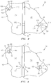
- FIG. 1 is a cross-sectional illustration of a mold 10 for casting a hollow workpiece.
- the mold 10 includes a casting shell 12, one or more casting cores 14 and 16, and one or more casting pins 18, 20 and 22.
- the casting cores may include a first casting core 14 and a second casting core 16.
- the first casting core 14 includes a core sidewall 30, a first core surface 32, a second core surface 34 and at least one aperture 36.
- the core sidewall 30 extends between the first core surface 32 and the second core surface 34.
- the aperture 36 may have a rectangular cross-sectional geometry that extends through the first casting core 14.
- the aperture 36 includes an aperture sidewall 38 that extends between the first core surface 32 and the second core surface 34.
- the third casting pin 22 supports the first casting core 14 and the second casting core 16 within the casting shell 12, and aligns adjacent ends of the first casting core 14 and the second casting core 16.
- the third casting pin 22, for example, extends through the gap 116 between the first and second sides 117 and 119 of the interior shell surface 26.
- a first region 126 of the first casting core 14 adjacent to the core sidewall 30 extends into the first notch 108, and the core sidewall 30 contacts the intermediate segment 102.
- a first region 128 of the second casting core 16 adjacent to the core sidewall 40 extends into the second notch 114, and the core sidewall 40 contacts the intermediate segment 102.
- the first support segment 90 extends from the first core surfaces 32 and 42 to the first side 117 of the interior shell surface 26.
- the second segment 96 extends from the second core surfaces 34 and 44 to the second side 119 of the interior shell surface 26.
Description
- This disclosure relates generally to a mold for casting a workpiece and, more particularly, to a mold that includes one or more casting pins.
- Various methods for investment casting (also referred to as "lost wax casting") are known in the art for manufacturing a hollow workpiece. An example of a hollow workpiece is a component such as a hollow rotor blade for a gas turbine engine. In one such method, molten metal is poured into a mold cavity defined between an exterior core surface of a casting core and an interior shell surface of a casting shell. The casting core may be supported within the casting shell using a plurality of casting pins. Each casting pin typically extends from the exterior core surface through the mold cavity and into the casting shell. Therefore, while a casting pin may prevent the casting core from moving in a direction that extends therethrough, the casting pin typically does not prevent the casting core from moving in an opposite direction that extends away therefrom. Such casting pins therefore are typically used in pairs, where a first casting pin is arranged on one side of the casting core, and where a second casting pin is arranged on an opposite side of the casting core.
- A mold for casting a workpiece, having the features of the preamble of claim 1 is disclosed in
GB 2118078 A - According to the invention, there is provided a mold for casting a workpiece, as set forth in claim 1.
- The foregoing features and the operation of the invention will become more apparent in light of the following description and the accompanying drawings.
-
-
FIG. 1 is a cross-sectional illustration of a mold for casting a workpiece; -
FIG. 2 is a sectional illustration of the mold illustrated inFIG. 1 ; -
FIG. 3 is a sectional illustration of the mold illustrated inFIG. 1 ; -
FIG. 4 is an illustration of a casting pin; -
FIG. 5 is a cross-sectional illustration of the casting pin illustrated inFIG. 4 ; -
FIG. 6 is a sectional illustration of a mold for casting a workpiece that includes the casting pin illustrated inFIG. 4 ; -
FIG. 7 is a cross-sectional illustration of a mold for casting a workpiece, which falls outside the scope of the claims; and -
FIG. 8 is a cross-sectional illustration of a casting pin included in the mold illustrated inFIG. 7 . -
FIG. 1 is a cross-sectional illustration of amold 10 for casting a hollow workpiece. Themold 10 includes acasting shell 12, one ormore casting cores more casting pins - The
casting shell 12 includes ashell wall 24 that defines aninterior shell cavity 25. Theshell wall 24 extends between aninterior shell surface 26 and anexterior shell surface 28. - The casting cores may include a
first casting core 14 and asecond casting core 16. Thefirst casting core 14 includes acore sidewall 30, afirst core surface 32, asecond core surface 34 and at least oneaperture 36. Thecore sidewall 30 extends between thefirst core surface 32 and thesecond core surface 34. Referring toFIG. 2 , theaperture 36 may have a rectangular cross-sectional geometry that extends through thefirst casting core 14. Referring again toFIG. 1 , theaperture 36 includes anaperture sidewall 38 that extends between thefirst core surface 32 and thesecond core surface 34. - The
second casting core 16 includes acore sidewall 40, afirst core surface 42, asecond core surface 44 and at least one aperture 46 (seeFIG. 2 ). Thecore sidewall 40 extends between thefirst core surface 42 and thesecond core surface 44. Referring toFIG. 2 , theaperture 46 may have a rectangular cross-sectional geometry that extends through thesecond casting core 16. Theaperture 46 includes anaperture sidewall 48 that extends between thefirst core surface 42 and thesecond core surface 44. - Referring again to
FIG. 1 , the casting pins may include afirst casting pin 18, asecond casting pin 20, and athird casting pin 22. Eachcasting pin first pin end second pin end FIG. 3 , the pin sidewalls may include afirst pin sidewall second pin sidewall third pin sidewall fourth pin sidewall first pin sidewall fourth pin sidewall second pin sidewall third pin sidewall - Referring again to
FIG. 1 , eachcasting pin first support segment second support segment intermediate segment FIG. 2 ), and one or more notches. Thefirst support segment intermediate segment first pin end second support segment intermediate segment second pin end intermediate segment first support segment second support segment FIGS. 1 and2 , the notches may include afirst notch second notch first notch first pin sidewall first support segment second support segment second notch fourth pin sidewall first support segment second support segment FIG. 2 , the notches provide theintermediate segment - Referring to
FIG. 1 , thefirst casting core 14 and thesecond casting core 16 are arranged side-by-side within the interior shell cavity. Thecore sidewall 30 is separated from thecore sidewall 40 by agap 116. - The
first casting pin 18 and thesecond casting pin 20 respectively support thefirst casting core 14 and thesecond casting core 16 within thecasting shell 12. Thefirst casting pin 18, for example, extends through theaperture 36 between opposing first andsecond sides interior shell surface 26. Afirst region 118 of thefirst casting core 14 adjacent to theaperture sidewall 38 extends into thefirst notch 104. Asecond region 120 of thefirst casting core 14 adjacent to theaperture sidewall 38 extends into thesecond notch 110, and theaperture sidewall 38 contacts theintermediate segment 98. Thefirst support segment 86 extends from thefirst core surface 32 to thefirst side 117 of theinterior shell surface 26. Thesecond support segment 92 extends from thesecond core surface 34 to thesecond side 119 of theinterior shell surface 26. - The
third casting pin 22 supports thefirst casting core 14 and thesecond casting core 16 within thecasting shell 12, and aligns adjacent ends of thefirst casting core 14 and thesecond casting core 16. Thethird casting pin 22, for example, extends through thegap 116 between the first andsecond sides interior shell surface 26. Afirst region 126 of thefirst casting core 14 adjacent to thecore sidewall 30 extends into thefirst notch 108, and thecore sidewall 30 contacts theintermediate segment 102. Afirst region 128 of thesecond casting core 16 adjacent to thecore sidewall 40 extends into thesecond notch 114, and thecore sidewall 40 contacts theintermediate segment 102. Thefirst support segment 90 extends from thefirst core surfaces first side 117 of theinterior shell surface 26. Thesecond segment 96 extends from thesecond core surfaces second side 119 of theinterior shell surface 26. - In some embodiments, the casting
shell 12 and/or thecasting cores - During assembly, the casting pins 18, 20 and 22 are respectively mated to the
first casting core 14 and thesecond casting core 16. For example, referring toFIGS. 1-3 , thefirst support segment 86 is passed through theaperture 36 until theintermediate segment 98 is aligned with thefirst casting core 14. Thefirst support segment 86 and thesecond support segment 92 is twisted relative to theintermediate segment 98 and theaperture 36 such that the first support segment partially overlaps thefirst core surface 32 and the second support segment partially overlaps thesecond core surface 34. The first and thesecond support segments intermediate segment 98, for example, through plastic deformation at intersections between the support segments and the intermediate segment. - A wax die may be formed around the
first casting core 14 and thesecond casting core 16, and at least partially encapsulate the casting pins 18, 20 and 22. The castingshell 12 may subsequently be formed around the wax die, which may be removed to form theinterior shell cavity 25. Alternatively, one or more of the casting pins 18, 20 and 22 may be respectively mated to thefirst casting core 14 and thesecond casting core 16 after the wax die is formed around thefirst casting core 14 and thesecond casting core 16. -
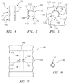
FIG. 4 illustrates an alternate embodiment of acasting pin 130.FIG. 5 is a cross-section illustration of thecasting pin 130 illustrated inFIG. 4 . Referring toFIGS. 4 and 5 , in contrast to the casting pins 18, 20 and 22 illustrated inFIG. 1 , thecasting pin 130 has a substantially square cross-sectional geometry, and includes a plurality ofcorner notches 132. Eachcorner notch 132 extends into anintermediate segment 134, at acorner 136 of thecasting pin 130, between first andsecond support segments FIG. 6 illustrates thecasting pin 130 connected to acasting core 142 through anaperture 144 having a substantially square cross-sectional geometry. -
FIG. 7 is a cross-sectional illustration of amold 146 for casting a workpiece that includes analternate casting pin 148 and which falls outside the scope of the invention.FIG. 8 is a cross-sectional illustration of thecasting pin 148 illustrated inFIG. 7 . Referring toFIGS. 7 and 8 , in contrast to the casting pins 18, 20 and 22 illustrated inFIG. 1 , thecasting pin 148 has a substantially circular cross-sectional geometry, and includes anannular notch 150. Theannular notch 150 extends into anintermediate segment 152 between first andsecond support segments annular notch 150 may be formed after thecasting pin 148 is inserted into anaperture 158 in acasting core 160 by axially compressing thecasting pin 148. - In other embodiments, the first and/or the second pin ends may extend into the casting shell. The first and/or the second pin ends may also extend into a wax die mold during the formation of the wax die to locate the casting cores.
- In still other embodiments, one or more of the support segments of one or more of the casting pin may have a stepped geometry where, for example, an outer step extends into the casting shell.
- While various embodiments of the present invention have been disclosed, it will be apparent to those of ordinary skill in the art that many more embodiments and implementations are possible within the scope of the invention. Accordingly, the present invention is defined by the appended claims.
Claims (13)
- A mold (10) for casting a workpiece, comprising:a casting shell (12) comprising an interior shell surface (26);a casting core (14,16) located within the shell (10), and comprising a sidewall (30,40) extending between a first core surface (32,42) and a second core surface (34,44); anda casting pin (18,20;130) supporting the core (14;16) within the shell (12), and comprising an intermediate segment (98,100;134) connected between a first support segment (86,88,90;138) and a second support segment (92,94,96;140), wherein the intermediate segment (98,100;134) contacts the sidewall (30,40), the first support segment (86,88,90;138) extends from the first core surface (32,42) to a first side (117) of the interior shell surface (26), and the second support segment (92,94,96;140) extends from the second core surface (34,44) to a second side (119) of the interior shell surface (26) that is opposite the first side (117), wherein the casting pin (18;130) further comprises a first notch (104;132) extending into the casting pin (18;130) between the first and the second support segments (86,92;154,156), and a first region (118) of the core adjacent to the sidewall (30) extends into the first notch (104;132); characterised in that:the core (14) further comprises an aperture (36; 136) extending between the first and the second core surfaces (30,32), and wherein the aperture (36; 136) comprises the sidewall (30); andin that the casting pin (18,20;130) and the aperture (36;136) are configured such that the first support segment (86,88,90;138) may be passed through the aperture (36;136) until the intermediate segment (98,100;134) is aligned with the casting core (14,16), whereupon the first support segment (86,88,90;138) and the second support segment (92,94,96;140) may be twisted such that first support segment (86,88,90;138) partially overlaps the first core surface (32) and the second support segment (92,94,96;140) partially overlaps the second core surface (34).
- The mold of claim 1, wherein the casting pin (18) further comprises a first pin sidewall (62) extending between a second pin sidewall (68) and a third pin sidewall (74), and the notch (104) extends into the first pin sidewall (62), and between the second and the third pin sidewalls (68,74).
- The mold of claim 1, wherein the casting pin (130) further comprises a corner (136) between a first pin sidewall and a second pin sidewall, and the notch (132) extends from the corner (136) partially into the first and the second sidewalls.
- The mold of any preceding claim, wherein the casting pin (14;130) further comprises a second notch (110;132) extending into the casting pin (14;130) between the first and the second support segments (86,92;138,140), and a second region (120) of the core (14;130) adjacent to the aperture (36;136) extends into the second notch (110;132).
- The mold of claim 4, wherein the first notch (110; 132) and the second notch (110;132) are arranged on substantially opposite sides of the casting pin (14;130).
- The mold of any preceding claim, wherein the core comprises a first core (14), and further including a further casting pin (22) that includes a notch extending into the casting pin (18;130) between the first and the second support segments (86,92;154,156) and that further supports a second core (16) within the shell (10), and wherein the further casting pin (22) is located in a gap (116) between the sidewall (30) of the first core (14) and a sidewall (40) of the second core (16).
- The mold of claim 6, wherein the further casting pin (22) aligns adjacent ends of the first and the second cores (14,16).
- The mold of claim 7, wherein the further casting pin (22) further comprises a second notch (114) extending into the further casting pin (22) between the first and the second support segments (90,96), and a first region (128) of the second core (16) adjacent to the sidewall (40) thereof extends into the second notch (114).
- The mold of any preceding claim, wherein at least one of the first and the second support segments (86,88,90;138;154,92,94,96;140) extends into the shell (12).
- The mold of any preceding claim, wherein the casting pin (18,20;130) is one of a plurality of casting pins that support the core (14,16) within the shell (12).
- The mold of any preceding claim, wherein the intermediate segment (98,100;134) comprises a rectangular cross-sectional geometry.
- The mold of claim 11, wherein the intermediate segment (98,100,102;134) comprises a square cross-sectional geometry.
- The mold of any preceding claim, wherein the shell (12) and the core (14,16) each comprises ceramic, and wherein the casting pin (18,20;130) comprises metal.
Applications Claiming Priority (1)
| Application Number | Priority Date | Filing Date | Title |
|---|---|---|---|
| US13/234,966 US9550230B2 (en) | 2011-09-16 | 2011-09-16 | Mold for casting a workpiece that includes one or more casting pins |
Publications (3)
| Publication Number | Publication Date |
|---|---|
| EP2570207A2 EP2570207A2 (en) | 2013-03-20 |
| EP2570207A3 EP2570207A3 (en) | 2017-04-26 |
| EP2570207B1 true EP2570207B1 (en) | 2020-03-25 |
Family
ID=46939593
Family Applications (1)
| Application Number | Title | Priority Date | Filing Date |
|---|---|---|---|
| EP12184534.1A Active EP2570207B1 (en) | 2011-09-16 | 2012-09-14 | Mold for casting a workpiece that includes one or more casting pins |
Country Status (2)
| Country | Link |
|---|---|
| US (1) | US9550230B2 (en) |
| EP (1) | EP2570207B1 (en) |
Families Citing this family (3)
| Publication number | Priority date | Publication date | Assignee | Title |
|---|---|---|---|---|
| WO2015126488A2 (en) | 2013-12-23 | 2015-08-27 | United Technologies Corporation | Lost core structural frame |
| CN107913980A (en) * | 2016-10-11 | 2018-04-17 | 北京百慕航材高科技股份有限公司 | Bend pipe mould |
| US11945025B1 (en) | 2023-04-06 | 2024-04-02 | Rtx Corporation | Method of wall control in multi-wall investment casting |
Family Cites Families (19)
| Publication number | Priority date | Publication date | Assignee | Title |
|---|---|---|---|---|
| US2017952A (en) * | 1935-02-04 | 1935-10-22 | Fed Foundry Supply Company | Chaplet |
| GB926399A (en) * | 1961-05-03 | 1963-05-15 | Howe Sound Co | Method of manufacturing complex air cooled turbine components |
| US3659645A (en) * | 1965-08-09 | 1972-05-02 | Trw Inc | Means for supporting core in open ended shell mold |
| US4487246A (en) * | 1982-04-12 | 1984-12-11 | Howmet Turbine Components Corporation | System for locating cores in casting molds |
| JPH091315A (en) * | 1995-04-12 | 1997-01-07 | Asahi Tec Corp | Method for casting wheel for vehicle |
| US5950705A (en) * | 1996-12-03 | 1999-09-14 | General Electric Company | Method for casting and controlling wall thickness |
| DE59904037D1 (en) * | 1998-01-23 | 2003-02-20 | Siemens Ag | CASTING DEVICE WITH CAST MOLD AND A POSITIONING ELEMENT |
| US6077006A (en) | 1998-05-01 | 2000-06-20 | Buffers Usa Inc. | Handle positioner for freight container twistlock |
| GB2346340A (en) * | 1999-02-03 | 2000-08-09 | Rolls Royce Plc | A ceramic core, a disposable pattern, a method of making a disposable pattern, a method of making a ceramic shell mould and a method of casting |
| US20040094287A1 (en) | 2002-11-15 | 2004-05-20 | General Electric Company | Elliptical core support and plug for a turbine bucket |
| US7036556B2 (en) | 2004-02-27 | 2006-05-02 | Oroflex Pin Development Llc | Investment casting pins |
| US7334985B2 (en) | 2005-10-11 | 2008-02-26 | United Technologies Corporation | Shroud with aero-effective cooling |
| US9133715B2 (en) | 2006-09-20 | 2015-09-15 | United Technologies Corporation | Structural members in a pedestal array |
| US7892652B2 (en) | 2007-03-13 | 2011-02-22 | United Technologies Corporation | Low stress metallic based coating |
| US20100136258A1 (en) | 2007-04-25 | 2010-06-03 | Strock Christopher W | Method for improved ceramic coating |
| US7887929B2 (en) | 2007-08-28 | 2011-02-15 | United Technologies Corporation | Oriented fiber ceramic matrix composite abradable thermal barrier coating |
| US7998604B2 (en) | 2007-11-28 | 2011-08-16 | United Technologies Corporation | Article having composite layer |
| US20090165988A1 (en) * | 2007-12-31 | 2009-07-02 | General Electric Company | Turbine airfoil casting method |
| US8707708B2 (en) | 2010-02-22 | 2014-04-29 | United Technologies Corporation | 3D non-axisymmetric combustor liner |
-
2011
- 2011-09-16 US US13/234,966 patent/US9550230B2/en active Active
-
2012
- 2012-09-14 EP EP12184534.1A patent/EP2570207B1/en active Active
Non-Patent Citations (1)
| Title |
|---|
| None * |
Also Published As
| Publication number | Publication date |
|---|---|
| US9550230B2 (en) | 2017-01-24 |
| EP2570207A3 (en) | 2017-04-26 |
| US20130068415A1 (en) | 2013-03-21 |
| EP2570207A2 (en) | 2013-03-20 |
Similar Documents
| Publication | Publication Date | Title |
|---|---|---|
| JP2015520677A (en) | Tool for producing a casting core for a turbine engine blade and method for producing the same | |
| JP2007295668A (en) | Method of manufacturing core with no caulking trace | |
| EP2570207B1 (en) | Mold for casting a workpiece that includes one or more casting pins | |
| JP6355839B2 (en) | Die casting system with ceramic mold for forming components usable in gas turbine engines | |
| JP7380989B2 (en) | Manufacture of string windings, permanent molds for string windings, and string windings | |
| JPWO2015111096A1 (en) | Laminated iron core manufacturing apparatus and laminated iron core manufacturing method | |
| EP2992982B1 (en) | Investment casting of engine parts | |
| US10081052B2 (en) | Casting of engine parts | |
| US20120223612A1 (en) | Method of manufacturing rotor core of electric rotating machine | |
| EP3369937B1 (en) | Method of manufacturing impeller | |
| JP2013176183A (en) | Mold stator | |
| JP2014104503A (en) | Shaving method of punching product, manufacturing method and manufacturing device | |
| JP5674693B2 (en) | Winding forming apparatus and winding forming method | |
| US20210346948A1 (en) | Method of forming a helix, permanent mold for forming a helix, and helix | |
| CN104924530B (en) | A kind of plastic compression mould for miniature electronic fuse part | |
| KR20100089171A (en) | Wax model metalic pattern assembly | |
| JP6629588B2 (en) | Die-casting mold, cast product produced using die-casting mold, and method for producing cast product using die-casting mold | |
| JP2009255303A (en) | Manufacturing method of mold | |
| CN210075029U (en) | Stator core positioning die and welding system | |
| EP3060363B1 (en) | Lost core molding for forming cooling passages | |
| US20110047779A1 (en) | Method for making molds with 3-dimensional cooling paths | |
| JP6476382B2 (en) | Manufacturing method of differential transformer | |
| JP5516840B2 (en) | Cylinder head casting mold and cylinder head casting method | |
| JP4783057B2 (en) | Molding method of powder molded body, powder molded body and sintered machine part | |
| JP2021052534A (en) | Resolver magnet wire disconnection prevention structure |
Legal Events
| Date | Code | Title | Description |
|---|---|---|---|
| PUAI | Public reference made under article 153(3) epc to a published international application that has entered the european phase |
Free format text: ORIGINAL CODE: 0009012 |
|
| AK | Designated contracting states |
Kind code of ref document: A2 Designated state(s): AL AT BE BG CH CY CZ DE DK EE ES FI FR GB GR HR HU IE IS IT LI LT LU LV MC MK MT NL NO PL PT RO RS SE SI SK SM TR |
|
| AX | Request for extension of the european patent |
Extension state: BA ME |
|
| RAP1 | Party data changed (applicant data changed or rights of an application transferred) |
Owner name: UNITED TECHNOLOGIES CORPORATION |
|
| PUAL | Search report despatched |
Free format text: ORIGINAL CODE: 0009013 |
|
| AK | Designated contracting states |
Kind code of ref document: A3 Designated state(s): AL AT BE BG CH CY CZ DE DK EE ES FI FR GB GR HR HU IE IS IT LI LT LU LV MC MK MT NL NO PL PT RO RS SE SI SK SM TR |
|
| AX | Request for extension of the european patent |
Extension state: BA ME |
|
| RIC1 | Information provided on ipc code assigned before grant |
Ipc: B22C 9/24 20060101ALI20170321BHEP Ipc: B22C 9/04 20060101AFI20170321BHEP Ipc: B22C 9/10 20060101ALI20170321BHEP |
|
| STAA | Information on the status of an ep patent application or granted ep patent |
Free format text: STATUS: REQUEST FOR EXAMINATION WAS MADE |
|
| 17P | Request for examination filed |
Effective date: 20171026 |
|
| RBV | Designated contracting states (corrected) |
Designated state(s): AL AT BE BG CH CY CZ DE DK EE ES FI FR GB GR HR HU IE IS IT LI LT LU LV MC MK MT NL NO PL PT RO RS SE SI SK SM TR |
|
| STAA | Information on the status of an ep patent application or granted ep patent |
Free format text: STATUS: EXAMINATION IS IN PROGRESS |
|
| 17Q | First examination report despatched |
Effective date: 20180202 |
|
| GRAP | Despatch of communication of intention to grant a patent |
Free format text: ORIGINAL CODE: EPIDOSNIGR1 |
|
| STAA | Information on the status of an ep patent application or granted ep patent |
Free format text: STATUS: GRANT OF PATENT IS INTENDED |
|
| INTG | Intention to grant announced |
Effective date: 20191008 |
|
| GRAS | Grant fee paid |
Free format text: ORIGINAL CODE: EPIDOSNIGR3 |
|
| GRAA | (expected) grant |
Free format text: ORIGINAL CODE: 0009210 |
|
| STAA | Information on the status of an ep patent application or granted ep patent |
Free format text: STATUS: THE PATENT HAS BEEN GRANTED |
|
| AK | Designated contracting states |
Kind code of ref document: B1 Designated state(s): AL AT BE BG CH CY CZ DE DK EE ES FI FR GB GR HR HU IE IS IT LI LT LU LV MC MK MT NL NO PL PT RO RS SE SI SK SM TR |
|
| REG | Reference to a national code |
Ref country code: GB Ref legal event code: FG4D |
|
| REG | Reference to a national code |
Ref country code: DE Ref legal event code: R096 Ref document number: 602012068693 Country of ref document: DE |
|
| REG | Reference to a national code |
Ref country code: AT Ref legal event code: REF Ref document number: 1247990 Country of ref document: AT Kind code of ref document: T Effective date: 20200415 Ref country code: IE Ref legal event code: FG4D |
|
| PG25 | Lapsed in a contracting state [announced via postgrant information from national office to epo] |
Ref country code: RS Free format text: LAPSE BECAUSE OF FAILURE TO SUBMIT A TRANSLATION OF THE DESCRIPTION OR TO PAY THE FEE WITHIN THE PRESCRIBED TIME-LIMIT Effective date: 20200325 Ref country code: FI Free format text: LAPSE BECAUSE OF FAILURE TO SUBMIT A TRANSLATION OF THE DESCRIPTION OR TO PAY THE FEE WITHIN THE PRESCRIBED TIME-LIMIT Effective date: 20200325 Ref country code: NO Free format text: LAPSE BECAUSE OF FAILURE TO SUBMIT A TRANSLATION OF THE DESCRIPTION OR TO PAY THE FEE WITHIN THE PRESCRIBED TIME-LIMIT Effective date: 20200625 |
|
| PG25 | Lapsed in a contracting state [announced via postgrant information from national office to epo] |
Ref country code: BG Free format text: LAPSE BECAUSE OF FAILURE TO SUBMIT A TRANSLATION OF THE DESCRIPTION OR TO PAY THE FEE WITHIN THE PRESCRIBED TIME-LIMIT Effective date: 20200625 Ref country code: LV Free format text: LAPSE BECAUSE OF FAILURE TO SUBMIT A TRANSLATION OF THE DESCRIPTION OR TO PAY THE FEE WITHIN THE PRESCRIBED TIME-LIMIT Effective date: 20200325 Ref country code: SE Free format text: LAPSE BECAUSE OF FAILURE TO SUBMIT A TRANSLATION OF THE DESCRIPTION OR TO PAY THE FEE WITHIN THE PRESCRIBED TIME-LIMIT Effective date: 20200325 Ref country code: HR Free format text: LAPSE BECAUSE OF FAILURE TO SUBMIT A TRANSLATION OF THE DESCRIPTION OR TO PAY THE FEE WITHIN THE PRESCRIBED TIME-LIMIT Effective date: 20200325 Ref country code: GR Free format text: LAPSE BECAUSE OF FAILURE TO SUBMIT A TRANSLATION OF THE DESCRIPTION OR TO PAY THE FEE WITHIN THE PRESCRIBED TIME-LIMIT Effective date: 20200626 |
|
| REG | Reference to a national code |
Ref country code: NL Ref legal event code: MP Effective date: 20200325 |
|
| REG | Reference to a national code |
Ref country code: LT Ref legal event code: MG4D |
|
| PG25 | Lapsed in a contracting state [announced via postgrant information from national office to epo] |
Ref country code: NL Free format text: LAPSE BECAUSE OF FAILURE TO SUBMIT A TRANSLATION OF THE DESCRIPTION OR TO PAY THE FEE WITHIN THE PRESCRIBED TIME-LIMIT Effective date: 20200325 |
|
| PG25 | Lapsed in a contracting state [announced via postgrant information from national office to epo] |
Ref country code: PT Free format text: LAPSE BECAUSE OF FAILURE TO SUBMIT A TRANSLATION OF THE DESCRIPTION OR TO PAY THE FEE WITHIN THE PRESCRIBED TIME-LIMIT Effective date: 20200818 Ref country code: SM Free format text: LAPSE BECAUSE OF FAILURE TO SUBMIT A TRANSLATION OF THE DESCRIPTION OR TO PAY THE FEE WITHIN THE PRESCRIBED TIME-LIMIT Effective date: 20200325 Ref country code: EE Free format text: LAPSE BECAUSE OF FAILURE TO SUBMIT A TRANSLATION OF THE DESCRIPTION OR TO PAY THE FEE WITHIN THE PRESCRIBED TIME-LIMIT Effective date: 20200325 Ref country code: SK Free format text: LAPSE BECAUSE OF FAILURE TO SUBMIT A TRANSLATION OF THE DESCRIPTION OR TO PAY THE FEE WITHIN THE PRESCRIBED TIME-LIMIT Effective date: 20200325 Ref country code: IS Free format text: LAPSE BECAUSE OF FAILURE TO SUBMIT A TRANSLATION OF THE DESCRIPTION OR TO PAY THE FEE WITHIN THE PRESCRIBED TIME-LIMIT Effective date: 20200725 Ref country code: RO Free format text: LAPSE BECAUSE OF FAILURE TO SUBMIT A TRANSLATION OF THE DESCRIPTION OR TO PAY THE FEE WITHIN THE PRESCRIBED TIME-LIMIT Effective date: 20200325 Ref country code: CZ Free format text: LAPSE BECAUSE OF FAILURE TO SUBMIT A TRANSLATION OF THE DESCRIPTION OR TO PAY THE FEE WITHIN THE PRESCRIBED TIME-LIMIT Effective date: 20200325 Ref country code: LT Free format text: LAPSE BECAUSE OF FAILURE TO SUBMIT A TRANSLATION OF THE DESCRIPTION OR TO PAY THE FEE WITHIN THE PRESCRIBED TIME-LIMIT Effective date: 20200325 |
|
| REG | Reference to a national code |
Ref country code: AT Ref legal event code: MK05 Ref document number: 1247990 Country of ref document: AT Kind code of ref document: T Effective date: 20200325 |
|
| REG | Reference to a national code |
Ref country code: DE Ref legal event code: R097 Ref document number: 602012068693 Country of ref document: DE |
|
| PG25 | Lapsed in a contracting state [announced via postgrant information from national office to epo] |
Ref country code: IT Free format text: LAPSE BECAUSE OF FAILURE TO SUBMIT A TRANSLATION OF THE DESCRIPTION OR TO PAY THE FEE WITHIN THE PRESCRIBED TIME-LIMIT Effective date: 20200325 Ref country code: DK Free format text: LAPSE BECAUSE OF FAILURE TO SUBMIT A TRANSLATION OF THE DESCRIPTION OR TO PAY THE FEE WITHIN THE PRESCRIBED TIME-LIMIT Effective date: 20200325 Ref country code: AT Free format text: LAPSE BECAUSE OF FAILURE TO SUBMIT A TRANSLATION OF THE DESCRIPTION OR TO PAY THE FEE WITHIN THE PRESCRIBED TIME-LIMIT Effective date: 20200325 Ref country code: ES Free format text: LAPSE BECAUSE OF FAILURE TO SUBMIT A TRANSLATION OF THE DESCRIPTION OR TO PAY THE FEE WITHIN THE PRESCRIBED TIME-LIMIT Effective date: 20200325 |
|
| PLBE | No opposition filed within time limit |
Free format text: ORIGINAL CODE: 0009261 |
|
| STAA | Information on the status of an ep patent application or granted ep patent |
Free format text: STATUS: NO OPPOSITION FILED WITHIN TIME LIMIT |
|
| PG25 | Lapsed in a contracting state [announced via postgrant information from national office to epo] |
Ref country code: PL Free format text: LAPSE BECAUSE OF FAILURE TO SUBMIT A TRANSLATION OF THE DESCRIPTION OR TO PAY THE FEE WITHIN THE PRESCRIBED TIME-LIMIT Effective date: 20200325 |
|
| 26N | No opposition filed |
Effective date: 20210112 |
|
| PG25 | Lapsed in a contracting state [announced via postgrant information from national office to epo] |
Ref country code: MC Free format text: LAPSE BECAUSE OF FAILURE TO SUBMIT A TRANSLATION OF THE DESCRIPTION OR TO PAY THE FEE WITHIN THE PRESCRIBED TIME-LIMIT Effective date: 20200325 |
|
| REG | Reference to a national code |
Ref country code: CH Ref legal event code: PL |
|
| PG25 | Lapsed in a contracting state [announced via postgrant information from national office to epo] |
Ref country code: SI Free format text: LAPSE BECAUSE OF FAILURE TO SUBMIT A TRANSLATION OF THE DESCRIPTION OR TO PAY THE FEE WITHIN THE PRESCRIBED TIME-LIMIT Effective date: 20200325 |
|
| REG | Reference to a national code |
Ref country code: BE Ref legal event code: MM Effective date: 20200930 |
|
| PG25 | Lapsed in a contracting state [announced via postgrant information from national office to epo] |
Ref country code: LU Free format text: LAPSE BECAUSE OF NON-PAYMENT OF DUE FEES Effective date: 20200914 |
|
| PG25 | Lapsed in a contracting state [announced via postgrant information from national office to epo] |
Ref country code: LI Free format text: LAPSE BECAUSE OF NON-PAYMENT OF DUE FEES Effective date: 20200930 Ref country code: IE Free format text: LAPSE BECAUSE OF NON-PAYMENT OF DUE FEES Effective date: 20200914 Ref country code: CH Free format text: LAPSE BECAUSE OF NON-PAYMENT OF DUE FEES Effective date: 20200930 Ref country code: BE Free format text: LAPSE BECAUSE OF NON-PAYMENT OF DUE FEES Effective date: 20200930 |
|
| PG25 | Lapsed in a contracting state [announced via postgrant information from national office to epo] |
Ref country code: TR Free format text: LAPSE BECAUSE OF FAILURE TO SUBMIT A TRANSLATION OF THE DESCRIPTION OR TO PAY THE FEE WITHIN THE PRESCRIBED TIME-LIMIT Effective date: 20200325 Ref country code: MT Free format text: LAPSE BECAUSE OF FAILURE TO SUBMIT A TRANSLATION OF THE DESCRIPTION OR TO PAY THE FEE WITHIN THE PRESCRIBED TIME-LIMIT Effective date: 20200325 Ref country code: CY Free format text: LAPSE BECAUSE OF FAILURE TO SUBMIT A TRANSLATION OF THE DESCRIPTION OR TO PAY THE FEE WITHIN THE PRESCRIBED TIME-LIMIT Effective date: 20200325 |
|
| PG25 | Lapsed in a contracting state [announced via postgrant information from national office to epo] |
Ref country code: MK Free format text: LAPSE BECAUSE OF FAILURE TO SUBMIT A TRANSLATION OF THE DESCRIPTION OR TO PAY THE FEE WITHIN THE PRESCRIBED TIME-LIMIT Effective date: 20200325 Ref country code: AL Free format text: LAPSE BECAUSE OF FAILURE TO SUBMIT A TRANSLATION OF THE DESCRIPTION OR TO PAY THE FEE WITHIN THE PRESCRIBED TIME-LIMIT Effective date: 20200325 |
|
| REG | Reference to a national code |
Ref country code: DE Ref legal event code: R081 Ref document number: 602012068693 Country of ref document: DE Owner name: RAYTHEON TECHNOLOGIES CORPORATION (N.D.GES.D.S, US Free format text: FORMER OWNER: UNITED TECHNOLOGIES CORPORATION, FARMINGTON, CONN., US |
|
| P01 | Opt-out of the competence of the unified patent court (upc) registered |
Effective date: 20230520 |
|
| PGFP | Annual fee paid to national office [announced via postgrant information from national office to epo] |
Ref country code: GB Payment date: 20230823 Year of fee payment: 12 |
|
| PGFP | Annual fee paid to national office [announced via postgrant information from national office to epo] |
Ref country code: FR Payment date: 20230822 Year of fee payment: 12 Ref country code: DE Payment date: 20230822 Year of fee payment: 12 |