JP6234888B2 - Image forming apparatus - Google Patents
Image forming apparatus Download PDFInfo
- Publication number
- JP6234888B2 JP6234888B2 JP2014130910A JP2014130910A JP6234888B2 JP 6234888 B2 JP6234888 B2 JP 6234888B2 JP 2014130910 A JP2014130910 A JP 2014130910A JP 2014130910 A JP2014130910 A JP 2014130910A JP 6234888 B2 JP6234888 B2 JP 6234888B2
- Authority
- JP
- Japan
- Prior art keywords
- exposure
- density
- image
- thin line
- control unit
- Prior art date
- Legal status (The legal status is an assumption and is not a legal conclusion. Google has not performed a legal analysis and makes no representation as to the accuracy of the status listed.)
- Expired - Fee Related
Links
Images


Landscapes
- Color, Gradation (AREA)
- Laser Beam Printer (AREA)
- Control Or Security For Electrophotography (AREA)
- Color Electrophotography (AREA)
- Facsimile Image Signal Circuits (AREA)
Description
本発明は、画像形成装置に関するものである。 The present invention relates to an image forming apparatus.
プリンター、複合機などの画像形成装置は、トナーやインクなどの色材を使用して印刷を行っている。ある画像形成装置は、印刷すべき画素に色材で形成されるドットを間引くことで、色材の消費量を低減している(例えば特許文献1参照)。 Image forming apparatuses such as printers and multifunction peripherals perform printing using color materials such as toner and ink. A certain image forming apparatus reduces consumption of color material by thinning out dots formed with color material on pixels to be printed (see, for example, Patent Document 1).
しかしながら、印刷すべき画像における細線においてドットを間引くと、細線が途切れて印刷されてしまうことがある。 However, if dots are thinned out in the thin line in the image to be printed, the thin line may be interrupted and printed.
他方、印字階調を低くしてドットを形成することで色材の消費量を低減することが考えられる。しかし、その場合においても、細線が途切れて印刷されてしまう可能性がある。例えば、電子写真方式の場合、細線の印字階調を低くすることで静電潜像の電位が十分に低くならず、トナーが付着しなくなってしまう可能性がある。また、この場合のドット径は、図8に示すように、最大印字階調(つまり最大露光量)でのドット径より小さくなるため、細線のエッジ部分のジャギーが目立ちやすくなってしまう。 On the other hand, it is conceivable to reduce color material consumption by forming dots by lowering the print gradation. However, even in that case, there is a possibility that the thin line is interrupted and printed. For example, in the case of the electrophotographic method, the potential of the electrostatic latent image is not sufficiently lowered by reducing the print gradation of the fine line, and there is a possibility that the toner does not adhere. Further, as shown in FIG. 8, the dot diameter in this case is smaller than the dot diameter at the maximum print gradation (that is, the maximum exposure amount), so that the jaggy at the edge portion of the thin line becomes conspicuous.
本発明は、上記の問題に鑑みてなされたものであり、印字階調を低くしたりドット間引きを行った際の細線の印刷画質の低下を抑える画像形成装置を得ることを目的とする。 The present invention has been made in view of the above problems, and an object of the present invention is to obtain an image forming apparatus that suppresses a decrease in print image quality of fine lines when the print gradation is lowered or dot thinning is performed.
本発明に係る画像形成装置は、感光体と、前記感光体に光を照射して印刷画像の静電潜像を形成する露光装置と、前記露光装置を制御する制御部とを備える。そして、前記制御部は、中間印字階調レベルの細線またはドット間引き済みの細線を印字する際に、前記細線のエッジ部分の低濃度側の所定領域に対して前記露光装置に微小露光を実行させる。そして、前記制御部は、前記細線が縦細線または斜め細線である場合、主走査方向に沿って特定の画素数だけ前記露光装置に微小露光を実行させ、前記細線が横細線である場合、前記細線のエッジ部分に隣接する特定数のラインに対して前記露光装置に微小露光を実行させる。また、前記制御部は、印字領域と前記印字領域に隣接する非印字領域とを含む複数のパッチ画像の前記非印字領域に対して、異なる露光量で前記露光装置に微小露光を実行させ、前記濃度センサーによる前記パッチ画像のトナー画像濃度測定結果に基づいて、前記細線のエッジ部分の低濃度側の所定領域に対する微小露光の露光量を決定する。その際、前記制御部は、前記露光量で1つのパッチ画像を現像させた後、前記濃度センサーによる前記パッチ画像のトナー画像濃度を取得し、取得した前記トナー画像濃度が所定濃度を超えたか否かを判定し、取得した前記トナー画像濃度が所定濃度を超えていない場合には、前記非印字領域の前記露光量を所定量だけ増加させて次の前記パッチ画像を現像させるようにして、前記パッチ画像のトナー画像濃度が所定濃度を超えるまで、前記露光量を初期値から所定量ずつ増加させ前記パッチ画像を順番に現像させていき、前記パッチ画像のトナー画像濃度が所定濃度を超えたときに、1つ前の前記露光量を、前記微小露光領域の露光量にセットする。
An image forming apparatus according to the present invention includes a photoconductor, an exposure device that irradiates light to the photoconductor to form an electrostatic latent image of a printed image, and a control unit that controls the exposure device. Then, the control unit causes the exposure apparatus to perform microexposure on a predetermined region on the low density side of the edge portion of the fine line when printing the fine line at the intermediate print gradation level or the thinned dot line. . When the thin line is a vertical thin line or an oblique thin line, the control unit causes the exposure apparatus to perform microexposure for a specific number of pixels along the main scanning direction, and when the thin line is a horizontal thin line, The exposure apparatus is caused to perform microexposure on a specific number of lines adjacent to the edge portion of the thin line. Further, the control unit causes the exposure apparatus to perform microexposure with different exposure amounts for the non-printing areas of a plurality of patch images including a printing area and a non-printing area adjacent to the printing area, Based on the toner image density measurement result of the patch image by the density sensor, the exposure amount of minute exposure for a predetermined area on the low density side of the edge portion of the fine line is determined. At that time, after developing one patch image with the exposure amount, the control unit acquires the toner image density of the patch image by the density sensor, and whether or not the acquired toner image density exceeds a predetermined density If the acquired toner image density does not exceed a predetermined density, the next patch image is developed by increasing the exposure amount of the non-printing area by a predetermined amount, and When the toner image density of the patch image exceeds the predetermined density, the exposure amount is increased by a predetermined amount from the initial value to develop the patch image in order, and when the toner image density of the patch image exceeds the predetermined density In addition, the previous exposure amount is set to the exposure amount of the minute exposure region.
本発明によれば、印字階調を低くしたりドット間引きを行った際の細線の印刷画質の低下が抑えられる。 According to the present invention, it is possible to suppress a decrease in print quality of a fine line when a print gradation is lowered or dot thinning is performed.
以下、図に基づいて本発明の実施の形態を説明する。 Hereinafter, embodiments of the present invention will be described with reference to the drawings.
実施の形態1. Embodiment 1 FIG.
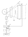
図1は、本発明の実施の形態に係る画像処理装置の機械的な内部構成の一部を示す側面図である。この画像処理装置は、プリンター、ファクシミリ装置、複写機、複合機などといった、電子写真方式の印刷機能を有する画像形成装置である。 FIG. 1 is a side view showing a part of a mechanical internal configuration of an image processing apparatus according to an embodiment of the present invention. This image processing apparatus is an image forming apparatus having an electrophotographic printing function, such as a printer, a facsimile machine, a copying machine, or a multifunction machine.
この実施の形態の画像処理装置は、タンデム方式のカラー現像装置を有する。このカラー現像装置は、感光体ドラム1a〜1d、露光装置2a〜2dおよび現像装置3a〜3dを有する。感光体ドラム1a〜1dは、シアン、マゼンタ、イエローおよびブラックの4色の感光体である。露光装置2a〜2dは、感光体ドラム1a〜1dへレーザー光を照射して静電潜像を形成する装置である。露光装置2a〜2dは、レーザー光の光源であるレーザーダイオード、およびそのレーザー光を感光体ドラム1a〜1dへ導く光学素子(レンズ、ミラー、ポリゴンミラーなど)を有するレーザースキャニングユニットである。
The image processing apparatus of this embodiment has a tandem color developing apparatus. The color developing device includes
さらに、感光体ドラム1a〜1dの周囲には、スコロトロン等の帯電器、クリーニング装置、除電器などが配置されている。クリーニング装置は、1次転写後に、感光体ドラム1a〜1d上の残留トナーを除去し、除電器は、1次転写後に、感光体ドラム1a〜1dを除電する。
Further, around the
現像装置3a〜3dには、シアン、マゼンタ、イエローおよびブラックの4色のトナーが充填されているトナーカートリッジがそれぞれ装着され、トナーカートリッジからトナーが供給され、キャリアとともに現像剤を構成する。現像装置3a〜3dは、そのトナーを感光体ドラム1a〜1d上の静電潜像に付着させてトナー画像を形成する。
To the developing
感光体ドラム1a、露光装置2a、および現像装置3aにより、マゼンタの現像が行われ、感光体ドラム1b、露光装置2b、および現像装置3bにより、シアンの現像が行われ、感光体ドラム1c、露光装置2c、および現像装置3cにより、イエローの現像が行われ、感光体ドラム1d、露光装置2d、および現像装置3dにより、ブラックの現像が行われる。
The
中間転写ベルト4は、感光体ドラム1a〜1dに接触し、感光体ドラム1a〜1d上のトナー画像を1次転写される環状の像担持体である。中間転写ベルト4は、駆動ローラー5に張架され、駆動ローラー5からの駆動力によって、感光体ドラム1dとの接触位置から感光体ドラム1aとの接触位置への方向へ周回していく。
The
転写ローラー6は、搬送されてくる用紙を中間転写ベルト4に接触させ、中間転写ベルト4上のトナー画像を用紙に2次転写する。なお、トナー画像を転写された用紙は、定着器9へ搬送され、トナー画像が用紙へ定着される。
The transfer roller 6 brings the conveyed paper into contact with the
ローラー7は、クリーニングブラシを有し、クリーニングブラシを中間転写ベルト4に接触させ、用紙へのトナー画像の転写後に中間転写ベルト4に残ったトナーを除去する。
The roller 7 has a cleaning brush, and the cleaning brush is brought into contact with the
センサー8は、各種調整用のパッチ画像などのトナー画像の濃度測定に使用されるセンサーであって、中間転写ベルト4に光線を照射し、その反射光を検出する。トナー濃度調整の際、センサー8は、中間転写ベルト4の所定の箇所に光線を照射し光線の反射光(測定光)を検出し、その光量に応じた電気信号を出力する。
The
図2は、図1における露光装置2aおよび周辺回路の構成例を示す図である。図3は、図1に示す画像形成装置の電気的な構成の一部を示すブロック図である。なお、図2に示す露光装置2aは、感光体ドラム1aに光を入射して静電潜像を形成する。感光体ドラム1b〜1d用の露光装置2b〜2dも、露光装置2aと同様の構成を有する。
FIG. 2 is a diagram showing a configuration example of the
図2において、露光装置2aは、レーザーダイオード11と、光学系12と、ポリゴンミラー13と、光センサー14と、ドライバー回路15と、制御部16と、画像処理部17とを有する。
In FIG. 2, the
レーザーダイオード11は、レーザー光線を出射する光源である。光学系12は、レーザーダイオード11からポリゴンミラー13までの間、および/またはポリゴンミラー13から感光体ドラム1aおよび光センサー14までの間に配置された各種レンズ群である。光学系12には、fθレンズなどが使用される。
The
また、ポリゴンミラー13は、感光体ドラム1aの軸に対して垂直な軸を有し、その軸に垂直な断面が多角形であり、その側面がミラーとなっている素子である。ポリゴンミラー13は、その軸を中心に回転し、レーザーダイオード11から出射した光線を感光体ドラム1aの軸方向(主走査方向)に沿って走査する。
The
また、光センサー14は、主走査同期信号を生成するためにポリゴンミラー13により走査された光を受光するセンサーである。光センサー14は、光が入射すると、光量に応じた出力電圧を誘起する。光センサー14は、光が走査される線上の所定の位置に配置され、光のスポットがその位置を通過するタイミングを検出するために使用される。
The
また、ドライバー回路15は、光センサー14の主走査同期信号に基づいて主走査方向の同期を取りつつ、駆動信号に従ってレーザーダイオード11を発光させる。
The
また、制御部16は、上述のローラーなどを駆動する図示せぬ駆動源、1次転写バイアスを印加するバイアス回路、現像装置3a〜3d、露光装置2a〜2dなどを制御して、トナー画像の現像、転写および定着、並びに給紙、印刷および排紙を実行させる。さらに、制御部16は、画像処理部17からの画像データの各画素の値に対応する駆動信号を出力して露光装置2aの光量を制御する。つまり、制御部16は、感光体ドラム1aに入射する光の光量(各画素の光量)を制御する。
The
図4および図5は、図2および図3における制御部16が露光装置2a〜2dを制御することで形成される、細線のエッジ部分の低濃度側の微小露光領域について説明する図である。図4は、細線が縦細線である場合の微小露光領域について説明する図であり、図5は、細線が横細線である場合の微小露光領域について説明する図である。
4 and 5 are diagrams for explaining a micro exposure region on the low density side of the edge portion of the thin line formed by the
制御部16は、各トナー色について、画素値が均一な中間印字階調レベルの細線またはドット間引き済みの細線を印字する際に、その細線のエッジ部分の低濃度側の所定領域(以下、微小露光領域という)に対して露光装置2a〜2dに微小露光を実行させる。なお、この実施の形態では、細線は、1ドット以上でありかつ3ドット以下の幅の線である。
For each toner color, the
例えばトナー消費量を削減するために、制御部16は、各トナー色について、必要に応じて、画素値が均一な中間印字階調レベルの細線またはドット間引き済みの細線を印字する。そのようなトナー消費量削減を行うか否かは、ユーザーによる設定に基づいて決定されてもよいし、画像内容などに基づいて自動的に決定されるようにしてもよい。
For example, in order to reduce toner consumption, the
ここでは、微小露光は、微小露光による潜像電位によってトナーが感光体ドラム1a〜1dに付着しない露光量とされる。この実施の形態では、微小露光は、各画素に対して、微小露光による潜像電位によってトナーが感光体ドラム1a〜1dに付着しない露光パルス幅での露光である。
Here, the fine exposure is an exposure amount at which the toner does not adhere to the
制御部16は、図4に示すように細線が縦細線(または斜め細線)である場合、主走査方向に沿って特定の画素数(図4では3画素)だけ露光装置2a〜2dに微小露光を実行させ、図5に示すように細線が横細線である場合、細線のエッジ部分に隣接する特定数(図5では2ライン)のラインに対して露光装置2a〜2dに微小露光を実行させる。
When the thin line is a vertical thin line (or diagonal thin line) as shown in FIG. 4, the
なお、図4に示す細線は、中間印字階調レベルの細線であり、図5に示す細線は、毎5ドットのうちの1ドットを間引きした、ドット間引き済みの細線である。 4 is an intermediate print gradation level thin line, and the thin line shown in FIG. 5 is a thin line that has been thinned out by thinning out one dot out of every five dots.
画像処理部17は、色変換、スクリーン処理などの画像処理を実行し、画像処理後の画像データを制御部16に供給する。
The
次に、上記画像形成装置の動作について説明する。図6は、図1に示す画像形成装置の動作を説明する図である。ここでは、細線が中間印字階調レベル(飽和値が15である場合の9)の1ドット幅の縦細線である場合の動作について説明する。 Next, the operation of the image forming apparatus will be described. FIG. 6 is a diagram for explaining the operation of the image forming apparatus shown in FIG. Here, the operation in the case where the fine line is a one-dot wide vertical fine line at the intermediate print gradation level (9 when the saturation value is 15) will be described.
図6に示すように、制御部16は、画素クロックに同期して、画像処理部17から供給される画像データの値に基づき、主走査方向に沿って各画素に対応する駆動信号の値を特定し、駆動信号をドライバー回路15に供給している。
As shown in FIG. 6, the
画像データにおいて、背景部分の画素値は0となっており、細線の画素値は中間印字階調レベルである9となっている。 In the image data, the pixel value of the background portion is 0, and the pixel value of the fine line is 9 which is an intermediate print gradation level.
ここでは、制御部16は、画像データにおける画素値をパルス幅変調して駆動信号を生成している。したがって、画素値が0である場合、駆動信号は、その画素についての100%の期間、ローレベルとされ、画素値が15である場合、駆動信号は、その画素についての100%の期間、ハイレベルとされる。したがって、画素値が中間調を示している場合、駆動信号は、100%未満の期間、ハイレベルとされる。なお、図6における微小露光領域信号は、制御部16内で生成される、微小露光領域に対応する期間を指定する信号である。
Here, the
制御部16は、微小露光領域の画素値に拘わらず露光装置2a〜2dに微小露光を実行させる。
The
このとき、微小露光領域内の各画素について、制御部16は、所定の時間幅Tpdで露光させ、その画素の潜像電位を低下させる。時間幅Tpdは、その画素の潜像電位によって、トナーが付着しないように設定される。
At this time, the
このように、細線のエッジ部分周辺の潜像電位が低下するため、エッジ付近で細線の露光だけではトナーが付着しにくい箇所(細線内のドット中心とドット中心の中間のエッジ付近)にもトナーが付着するため、細線のジャギーが軽減される。 In this way, since the latent image potential around the edge of the fine line is lowered, the toner also adheres to the portion where the toner is difficult to adhere only by the fine line exposure near the edge (near the middle of the dot center and the dot center in the fine line). As a result, the jaggy of thin wires is reduced.
以上のように、上記実施の形態1によれば、制御部16は、中間印字階調レベルの細線またはドット間引き済みの細線を印字する際に、その細線のエッジ部分の低濃度側の所定領域(微小露光領域)に対して露光装置2a〜2dに微小露光を実行させる。
As described above, according to the first embodiment, when the
これにより、印字階調を低くしたりドット間引きを行った際の細線の印刷画質の低下が抑えられる。 Thereby, it is possible to suppress the deterioration of the print quality of the thin line when the print gradation is lowered or the dot thinning is performed.
実施の形態2.
実施の形態2に係る画像形成装置は、実施の形態1に係る画像形成装置と同様の構成を有する。ただし、実施の形態2では、制御部16が、微小露光領域の露光量の調整を行う。
The image forming apparatus according to the second embodiment has the same configuration as the image forming apparatus according to the first embodiment. However, in the second embodiment, the
実施の形態2では、制御部16は、複数のパッチ画像を現像させ、その際、複数のパッチ画像内の非印字領域に対して、異なる露光量で露光装置2a〜2dに微小露光を実行させる。そして、制御部16は、センサー8によるパッチ画像のトナー画像濃度測定結果に基づいて、細線のエッジ部分の低濃度側の所定領域に対する微小露光の露光量(ここでは、露光パルス幅)を決定する。
In the second embodiment, the
図7は、実施の形態2における複数のパッチ画像の一例を示す図である。 FIG. 7 is a diagram illustrating an example of a plurality of patch images in the second embodiment.
パッチ画像51〜53は、それぞれ、pドットの印字領域と印字領域に隣接するqドットの非印字領域とを交互にn個含む高さmラインの画像である。
Each of the
そして、制御部16は、パッチ画像51を現像させる際に、印字領域の印字階調を(例えば最大印字濃度で)一定とし、非印字領域の露光量を第1露光量に設定し、パッチ画像52を現像させる際に、非印字領域の露光量を第1露光量より多い第2露光量に設定し、パッチ画像53を現像させる際に、非印字領域の露光量を第2露光量より多い第3露光量に設定していく。ここでは、パッチ画像51,52,53の順に、非印字領域における1画素あたりの露光パルス幅を大きくしていく。
Then, when developing the
例えば、制御部16は、1つのパッチ画像を現像させた後、センサー8によるそのパッチ画像のトナー画像濃度(パッチ画像の平均濃度)を取得し、そのトナー画像濃度が所定濃度を超えたか否かを判定し、そのトナー画像濃度が所定濃度を超えていない場合には、露光量を所定量(ここでは所定パルス幅)だけ増加させて次の(1つの)パッチ画像を現像させる。そして、制御部16は、パッチ画像のトナー画像濃度が所定濃度を超えるまで、露光量を初期値(例えばゼロ)から所定量ずつ増加させパッチ画像を順番に現像させていき、パッチ画像のトナー画像濃度が所定濃度を超えたときに、1つ前の露光量を、上述の微小露光領域の露光量にセットする。
For example, after developing one patch image, the
また、例えば、露光パルス幅が0レベル〜15レベルの16段階で離散的に設定される場合、センサー8によって濃度変化が検出されるレベルより1つ下のレベルが、微小露光領域の1画素あたりの露光パルス幅Tpdに設定される。
Further, for example, when the exposure pulse width is discretely set in 16 steps of 0 level to 15 level, the level one level lower than the level at which the density change is detected by the
これにより、微小露光領域の露光量が、装置の状態などに応じて適切な量に調整される。なお、この調整は、微小露光を行う直前、装置内の温度や湿度が変化したとき、所定印字枚数ごとなどといった所定のタイミングで実行される。 Thereby, the exposure amount of the minute exposure region is adjusted to an appropriate amount according to the state of the apparatus. This adjustment is executed at a predetermined timing, such as every time the number of printed sheets is reached, when the temperature or humidity in the apparatus changes immediately before the minute exposure.
なお、実施の形態2に係る画像形成装置のその他の動作については実施の形態1のものと同様であるので、その説明を省略する。 Since other operations of the image forming apparatus according to the second embodiment are the same as those of the first embodiment, the description thereof is omitted.
以上のように、上記実施の形態2によれば、微小露光領域の露光量が適切に調整される。 As described above, according to the second embodiment, the exposure amount in the minute exposure area is appropriately adjusted.
なお、上述の各実施の形態は、本発明の好適な例であるが、本発明は、これらに限定されるものではなく、本発明の要旨を逸脱しない範囲において、種々の変形、変更が可能である。 Each embodiment described above is a preferred example of the present invention, but the present invention is not limited to these, and various modifications and changes can be made without departing from the scope of the present invention. It is.
本発明は、例えば、電子写真方式の画像形成装置に適用可能である。 The present invention is applicable to, for example, an electrophotographic image forming apparatus.
1a〜1d 感光体ドラム(感光体の例)
2a〜2d 露光装置
8 センサー(濃度センサーの一例)
16 制御部
51〜53 パッチ画像
1a to 1d photoconductor drum (example of photoconductor)
2a to
16 Control unit
51-53 Patch image
Claims (3)
前記感光体に光を照射して印刷画像の静電潜像を形成する露光装置と、
前記露光装置を制御する制御部と、
トナー画像の濃度を測定する濃度センサーとを備え、
前記制御部は、中間印字階調レベルの細線またはドット間引き済みの細線を印字する際に、前記細線のエッジ部分の低濃度側の所定領域に対して前記露光装置に微小露光を実行させ、
前記制御部は、前記細線が縦細線または斜め細線である場合、主走査方向に沿って特定の画素数だけ前記露光装置に微小露光を実行させ、前記細線が横細線である場合、前記細線のエッジ部分に隣接する特定数のラインに対して前記露光装置に微小露光を実行させ、
前記制御部は、印字領域と前記印字領域に隣接する非印字領域とを含む複数のパッチ画像の前記非印字領域に対して、異なる露光量で前記露光装置に微小露光を実行させ、前記濃度センサーによる前記パッチ画像のトナー画像濃度測定結果に基づいて、前記細線のエッジ部分の低濃度側の所定領域に対する微小露光の露光量を決定し、
前記制御部は、1つの前記パッチ画像を現像させた後、前記濃度センサーによる前記パッチ画像のトナー画像濃度を取得し、取得した前記トナー画像濃度が所定濃度を超えたか否かを判定し、取得した前記トナー画像濃度が所定濃度を超えていない場合には、前記非印字領域の前記露光量を所定量だけ増加させて次の前記パッチ画像を現像させるようにして、前記パッチ画像のトナー画像濃度が所定濃度を超えるまで、前記露光量を初期値から所定量ずつ増加させ前記パッチ画像を順番に現像させていき、前記パッチ画像のトナー画像濃度が所定濃度を超えたときに、1つ前の前記露光量を、前記微小露光領域の露光量にセットすること、
を特徴とする画像形成装置。 A photoreceptor,
An exposure device that irradiates the photoreceptor with light to form an electrostatic latent image of a printed image;
A control unit for controlling the exposure apparatus ;
A density sensor for measuring the density of the toner image ,
The control unit, when printing a thin line of the intermediate print gradation level or a thin line after dot thinning , causes the exposure apparatus to perform micro exposure on a predetermined area on the low density side of the edge portion of the fine line ,
When the thin line is a vertical thin line or an oblique thin line, the control unit causes the exposure apparatus to perform microexposure for a specific number of pixels along the main scanning direction, and when the thin line is a horizontal thin line, Causing the exposure apparatus to perform microexposure on a specific number of lines adjacent to the edge portion
The control unit causes the exposure apparatus to perform minute exposure with different exposure amounts on the non-printing areas of a plurality of patch images including a printing area and a non-printing area adjacent to the printing area, and the density sensor Based on the toner image density measurement result of the patch image according to the above, determine the exposure amount of the micro exposure for a predetermined area on the low density side of the edge portion of the fine line,
The control unit develops one patch image, acquires the toner image density of the patch image by the density sensor, determines whether the acquired toner image density exceeds a predetermined density, and acquires the toner image density If the toner image density does not exceed a predetermined density, the toner image density of the patch image is developed by increasing the exposure amount of the non-printing area by a predetermined amount and developing the next patch image. The exposure amount is increased by a predetermined amount from the initial value until the density exceeds a predetermined density, and the patch images are sequentially developed. When the toner image density of the patch image exceeds the predetermined density, the previous exposure is increased. Setting the exposure amount to the exposure amount of the minute exposure region;
An image forming apparatus.
Priority Applications (1)
| Application Number | Priority Date | Filing Date | Title |
|---|---|---|---|
| JP2014130910A JP6234888B2 (en) | 2014-06-26 | 2014-06-26 | Image forming apparatus |
Applications Claiming Priority (1)
| Application Number | Priority Date | Filing Date | Title |
|---|---|---|---|
| JP2014130910A JP6234888B2 (en) | 2014-06-26 | 2014-06-26 | Image forming apparatus |
Publications (2)
| Publication Number | Publication Date |
|---|---|
| JP2016009144A JP2016009144A (en) | 2016-01-18 |
| JP6234888B2 true JP6234888B2 (en) | 2017-11-22 |
Family
ID=55226711
Family Applications (1)
| Application Number | Title | Priority Date | Filing Date |
|---|---|---|---|
| JP2014130910A Expired - Fee Related JP6234888B2 (en) | 2014-06-26 | 2014-06-26 | Image forming apparatus |
Country Status (1)
| Country | Link |
|---|---|
| JP (1) | JP6234888B2 (en) |
Families Citing this family (1)
| Publication number | Priority date | Publication date | Assignee | Title |
|---|---|---|---|---|
| JP2021063959A (en) * | 2019-10-17 | 2021-04-22 | 京セラドキュメントソリューションズ株式会社 | Image forming apparatus |
Family Cites Families (8)
| Publication number | Priority date | Publication date | Assignee | Title |
|---|---|---|---|---|
| JP2002108028A (en) * | 2000-09-27 | 2002-04-10 | Toshiba Corp | Image forming device |
| JP2004317716A (en) * | 2003-04-15 | 2004-11-11 | Canon Inc | Image forming apparatus |
| JP4984525B2 (en) * | 2005-12-26 | 2012-07-25 | 富士ゼロックス株式会社 | Image forming apparatus |
| JP4912270B2 (en) * | 2007-10-16 | 2012-04-11 | キヤノン株式会社 | Image processing apparatus and control method thereof |
| JP5581189B2 (en) * | 2010-11-30 | 2014-08-27 | 京セラドキュメントソリューションズ株式会社 | Image forming apparatus |
| JP5896203B2 (en) * | 2011-07-22 | 2016-03-30 | 富士ゼロックス株式会社 | Image processing apparatus, image forming apparatus, and program |
| JP6021390B2 (en) * | 2012-04-05 | 2016-11-09 | キヤノン株式会社 | Image forming apparatus |
| JP6027851B2 (en) * | 2012-10-26 | 2016-11-16 | キヤノン株式会社 | Image processing apparatus, image processing method, and program |
-
2014
- 2014-06-26 JP JP2014130910A patent/JP6234888B2/en not_active Expired - Fee Related
Also Published As
| Publication number | Publication date |
|---|---|
| JP2016009144A (en) | 2016-01-18 |
Similar Documents
| Publication | Publication Date | Title |
|---|---|---|
| JP2012114510A (en) | Image forming apparatus and image forming method | |
| JP5269012B2 (en) | Image forming apparatus | |
| JP5875543B2 (en) | Image forming apparatus | |
| JP6129118B2 (en) | Image forming apparatus and calibration method | |
| JP5885688B2 (en) | Image forming apparatus | |
| JP6234888B2 (en) | Image forming apparatus | |
| JP5812960B2 (en) | Image forming apparatus | |
| JP6210323B2 (en) | Image forming apparatus | |
| JP6864852B2 (en) | Image forming device | |
| JP6091408B2 (en) | Image forming apparatus | |
| JP6394993B2 (en) | Image forming apparatus and toner consumption calculation method | |
| JP6091404B2 (en) | Image forming apparatus | |
| US9395670B2 (en) | Image forming apparatus that reduces variation of count of printable sheets per toner container, image forming method, and recording medium | |
| JP5918119B2 (en) | Image forming apparatus | |
| JP5751009B2 (en) | Image forming apparatus, image forming method, and computer program | |
| JP6788804B2 (en) | Image forming device | |
| JP6748923B2 (en) | Image forming device | |
| JP6165112B2 (en) | Image forming apparatus | |
| JP6099621B2 (en) | Image forming apparatus | |
| JP6365888B2 (en) | Image forming apparatus | |
| JP2021196586A (en) | Image forming apparatus | |
| JP2020154173A (en) | Image forming apparatus | |
| JP2014068084A (en) | Image forming apparatus | |
| KR100602270B1 (en) | Method and apparqtus for skew compensation in coluor print | |
| JP2019219541A (en) | Image forming apparatus |
Legal Events
| Date | Code | Title | Description |
|---|---|---|---|
| A621 | Written request for application examination |
Free format text: JAPANESE INTERMEDIATE CODE: A621 Effective date: 20160721 |
|
| A977 | Report on retrieval |
Free format text: JAPANESE INTERMEDIATE CODE: A971007 Effective date: 20170327 |
|
| A131 | Notification of reasons for refusal |
Free format text: JAPANESE INTERMEDIATE CODE: A131 Effective date: 20170413 |
|
| A521 | Request for written amendment filed |
Free format text: JAPANESE INTERMEDIATE CODE: A523 Effective date: 20170526 |
|
| TRDD | Decision of grant or rejection written | ||
| A01 | Written decision to grant a patent or to grant a registration (utility model) |
Free format text: JAPANESE INTERMEDIATE CODE: A01 Effective date: 20170817 |
|
| R155 | Notification before disposition of declining of application |
Free format text: JAPANESE INTERMEDIATE CODE: R155 |
|
| A61 | First payment of annual fees (during grant procedure) |
Free format text: JAPANESE INTERMEDIATE CODE: A61 Effective date: 20171025 |
|
| R150 | Certificate of patent or registration of utility model |
Ref document number: 6234888 Country of ref document: JP Free format text: JAPANESE INTERMEDIATE CODE: R150 |
|
| LAPS | Cancellation because of no payment of annual fees |