JP6233725B2 - Contactless charging system - Google Patents
Contactless charging system Download PDFInfo
- Publication number
- JP6233725B2 JP6233725B2 JP2015508094A JP2015508094A JP6233725B2 JP 6233725 B2 JP6233725 B2 JP 6233725B2 JP 2015508094 A JP2015508094 A JP 2015508094A JP 2015508094 A JP2015508094 A JP 2015508094A JP 6233725 B2 JP6233725 B2 JP 6233725B2
- Authority
- JP
- Japan
- Prior art keywords
- charging
- coil
- charged
- car navigation
- information
- Prior art date
- Legal status (The legal status is an assumption and is not a legal conclusion. Google has not performed a legal analysis and makes no representation as to the accuracy of the status listed.)
- Active
Links
- 238000004891 communication Methods 0.000 claims description 39
- 238000001514 detection method Methods 0.000 claims description 8
- 238000004804 winding Methods 0.000 claims description 6
- 238000009434 installation Methods 0.000 description 14
- 238000000034 method Methods 0.000 description 10
- 230000008569 process Effects 0.000 description 10
- 230000004907 flux Effects 0.000 description 6
- 238000004364 calculation method Methods 0.000 description 3
- 239000004020 conductor Substances 0.000 description 3
- 230000003247 decreasing effect Effects 0.000 description 3
- 238000010586 diagram Methods 0.000 description 3
- 239000000463 material Substances 0.000 description 3
- 239000000126 substance Substances 0.000 description 3
- 229920003002 synthetic resin Polymers 0.000 description 3
- 239000000057 synthetic resin Substances 0.000 description 3
- 238000005516 engineering process Methods 0.000 description 2
- WABPQHHGFIMREM-UHFFFAOYSA-N lead(0) Chemical compound [Pb] WABPQHHGFIMREM-UHFFFAOYSA-N 0.000 description 2
- 239000000758 substrate Substances 0.000 description 2
- 230000008901 benefit Effects 0.000 description 1
- 239000000919 ceramic Substances 0.000 description 1
- 230000007812 deficiency Effects 0.000 description 1
- 238000004070 electrodeposition Methods 0.000 description 1
- 230000006870 function Effects 0.000 description 1
- 230000020169 heat generation Effects 0.000 description 1
- 239000002184 metal Substances 0.000 description 1
- 230000000149 penetrating effect Effects 0.000 description 1
- 230000002093 peripheral effect Effects 0.000 description 1
- 238000011084 recovery Methods 0.000 description 1
- 230000004044 response Effects 0.000 description 1
Images


Classifications
-
- H—ELECTRICITY
- H02—GENERATION; CONVERSION OR DISTRIBUTION OF ELECTRIC POWER
- H02J—CIRCUIT ARRANGEMENTS OR SYSTEMS FOR SUPPLYING OR DISTRIBUTING ELECTRIC POWER; SYSTEMS FOR STORING ELECTRIC ENERGY
- H02J50/00—Circuit arrangements or systems for wireless supply or distribution of electric power
- H02J50/005—Mechanical details of housing or structure aiming to accommodate the power transfer means, e.g. mechanical integration of coils, antennas or transducers into emitting or receiving devices
-
- H—ELECTRICITY
- H02—GENERATION; CONVERSION OR DISTRIBUTION OF ELECTRIC POWER
- H02J—CIRCUIT ARRANGEMENTS OR SYSTEMS FOR SUPPLYING OR DISTRIBUTING ELECTRIC POWER; SYSTEMS FOR STORING ELECTRIC ENERGY
- H02J50/00—Circuit arrangements or systems for wireless supply or distribution of electric power
- H02J50/60—Circuit arrangements or systems for wireless supply or distribution of electric power responsive to the presence of foreign objects, e.g. detection of living beings
-
- H—ELECTRICITY
- H02—GENERATION; CONVERSION OR DISTRIBUTION OF ELECTRIC POWER
- H02J—CIRCUIT ARRANGEMENTS OR SYSTEMS FOR SUPPLYING OR DISTRIBUTING ELECTRIC POWER; SYSTEMS FOR STORING ELECTRIC ENERGY
- H02J50/00—Circuit arrangements or systems for wireless supply or distribution of electric power
- H02J50/80—Circuit arrangements or systems for wireless supply or distribution of electric power involving the exchange of data, concerning supply or distribution of electric power, between transmitting devices and receiving devices
-
- H—ELECTRICITY
- H02—GENERATION; CONVERSION OR DISTRIBUTION OF ELECTRIC POWER
- H02J—CIRCUIT ARRANGEMENTS OR SYSTEMS FOR SUPPLYING OR DISTRIBUTING ELECTRIC POWER; SYSTEMS FOR STORING ELECTRIC ENERGY
- H02J7/00—Circuit arrangements for charging or depolarising batteries or for supplying loads from batteries
- H02J7/0042—Circuit arrangements for charging or depolarising batteries or for supplying loads from batteries characterised by the mechanical construction
-
- H—ELECTRICITY
- H02—GENERATION; CONVERSION OR DISTRIBUTION OF ELECTRIC POWER
- H02J—CIRCUIT ARRANGEMENTS OR SYSTEMS FOR SUPPLYING OR DISTRIBUTING ELECTRIC POWER; SYSTEMS FOR STORING ELECTRIC ENERGY
- H02J50/00—Circuit arrangements or systems for wireless supply or distribution of electric power
- H02J50/10—Circuit arrangements or systems for wireless supply or distribution of electric power using inductive coupling
Description
本発明は、無接点充電システムに関する。 The present invention relates to a contactless charging system .
携帯電話等の携帯端末は、その機能が極めて高度となり、電力消費も大きくなっている。そのため、自動車内を含め、各所で充電が行えることが求められてきている。また、近年の傾向として、ケーブルを使わずに充電を行う、いわゆる無接点充電が脚光を浴びている。 Mobile terminals such as mobile phones have extremely advanced functions and large power consumption. For this reason, it has been demanded that charging can be performed at various places including inside the automobile. As a recent trend, so-called contactless charging, in which charging is performed without using a cable, has been in the spotlight.
このような無接点充電装置としては、携帯端末に充電する1次コイルと、この1次コイルの通電を制御する充電制御部を備え、1次コイルからの磁束によって携帯端末の2次コイルが受電することにより、充電制御部は携帯端末に対して無接点(非接触)充電を行う技術が知られている(例えば、特許文献1参照)。 As such a non-contact charging device, a primary coil for charging the mobile terminal and a charge control unit for controlling energization of the primary coil are provided, and the secondary coil of the mobile terminal receives power by the magnetic flux from the primary coil. By doing so, a technology is known in which the charging control unit performs non-contact (non-contact) charging on the mobile terminal (see, for example, Patent Document 1).
また、様々な種類の携帯端末への充電を可能とするための特定規格(例えば、Qi規格など)が定められ、無接点充電装置、および被充電機器(携帯端末)の双方がその特定規格に準拠していれば、充電を行う技術も提案されている。 In addition, specific standards (for example, Qi standard) for enabling charging of various types of portable terminals are defined, and both the non-contact charging device and the device to be charged (mobile terminal) comply with the specific standards. If it complies, a technology for charging is also proposed.
上記の無接点充電装置は、次々と市場に投入された新しい携帯端末も、特定規格に準拠していることが確認できると、標準充電処理(特定規格に準拠した充電処理)により充電をするようになっている。 The above non-contact charging device seems to be charged by standard charging processing (charging processing complying with specific standards) when it can be confirmed that new mobile terminals put on the market one after another conform to specific standards. It has become.
ここで、標準充電処理について簡単に説明する。無接点充電装置が携帯端末側の2次コイルを検出し、携帯端末と通信可能となると、電池プロダクトナンバー(電池のメーカーID)、電池IDを携帯端末から取得する。これにより、無接点充電装置は、特定規格に対応した携帯端末であることが分かる。 Here, the standard charging process will be briefly described. When the contactless charging device detects the secondary coil on the mobile terminal side and can communicate with the mobile terminal, the battery product number (battery manufacturer ID) and battery ID are acquired from the mobile terminal. Thereby, it turns out that a non-contact charging device is a portable terminal corresponding to a specific standard.
次に、無接点充電装置は、少ない供給電力で充電を開始する。そして、携帯端末は、供給電力が十分であるか、不十分であるかのパケットを無接点充電装置に定期的に送信する。無接点充電装置は、その供給電力の過不足の量に合わせて、供給電力を可変する。また、無接点充電装置は、このパケットを所定時間(例えば、1.5秒)取得できない場合、及び、携帯端末から充電停止のパケットを取得した場合、充電を停止する。 Next, the contactless charging device starts charging with a small amount of supplied power. Then, the mobile terminal periodically transmits a packet indicating whether the supplied power is sufficient or insufficient to the contactless charging apparatus. The contactless charging device varies the supply power according to the amount of excess or deficiency of the supply power. Further, the contactless charging device stops charging when the packet cannot be acquired for a predetermined time (for example, 1.5 seconds) and when a charging stop packet is acquired from the mobile terminal.
無接点充電装置は、このような標準充電処理を行う際、例えば、無接点充電装置側の送電電力と携帯端末側の受電電力との電力差からコイル間の導電性異物を検知する。しかしながら、様々な種類の携帯端末への充電を可能とするための特定規格は、多種多様な2次コイルの形状または負荷である充電池の特性などに幅広く対応するものとなっている。すなわち、携帯端末の種別毎に電力差が異なってしまう。 When such a standard charging process is performed, the contactless charging device detects a conductive foreign matter between the coils based on, for example, a power difference between the transmitted power on the contactless charging device side and the received power on the portable terminal side. However, specific standards for enabling charging of various types of mobile terminals are widely compatible with various secondary coil shapes or rechargeable battery characteristics. That is, the power difference differs for each type of mobile terminal.
そのため、無接点充電装置は、携帯端末が特定規格に準拠しているというだけでは、電力差などの1次コイルと2次コイルの通電情報を用いた導電性異物の検知処理を精度良く行うことができないという問題がある。 Therefore, the contactless charging device accurately performs the process of detecting the conductive foreign matter using the energization information of the primary coil and the secondary coil, such as a power difference, simply because the portable terminal conforms to a specific standard. There is a problem that can not be.
本発明の目的は、導電性異物の検知精度を向上させ、安全性を高める無接点充電装置、被充電機器、無接点充電装置を備えた無接点充電システムを提供することである。 An object of the present invention improves the detection accuracy of the conductive materials, wireless charger apparatus to enhance the safety, to provide a non-contact charging system including the charging device, a non-contact charging device.
本発明の一態様に係る無接点充電システムは、被充電機器と、表示部を有するカーナビゲーション装置と、センターコンソールに配置され前記被充電機器に充電を行う無接点充電装置と、を備えた無接点充電システムであって、前記カーナビゲーション装置は、前記被充電機器の受電コイルのコイル形状、コイル径、コイル巻き数の少なくとも1つ以上を示すコイル情報を前記被充電機器から無線通信によって取得し、さらに、前記カーナビゲーション装置は前記コイル情報を車載LANで前記無接点充電装置に送信し、前記無接点充電装置は前記被充電機器に電力を供給する充電コイルを有し、さらに、前記被充電機器と前記充電コイルとの間の導電性異物を検出するため前記コイル情報に応じて理想給電効率を算出し、前記被充電機器の充電中の給電効率と前記理想給電効率の割合から前記導電性異物を検出し、前記カーナビゲーション装置に備えられた前記表示部に前記導電性異物の検出に関する表示を出力する構成を採る。 A non-contact charging system according to an aspect of the present invention includes a non-contact charging system , a car navigation device having a display unit, and a non-contact charging device that is arranged in a center console and charges the charging target device. In the contact charging system , the car navigation device acquires coil information indicating at least one of a coil shape, a coil diameter, and a coil winding number of a power receiving coil of the charged device from the charged device by wireless communication. further wherein the car navigation device transmits to the wireless charger apparatus said coil information in-vehicle LAN, the wireless charger apparatus includes a charging coil to supply power to the target charging device, further, the object to be charged calculating the ideal feed efficiency in response to the coil information for detecting conductive objects between the charging coil and devices, said target charging equipment Detecting said conductive materials power supply efficiency from the ratio of the ideal feed efficiency in the electrodeposition employs a configuration for outputting an indication as to the detection of the conductive foreign object on the display unit provided in the car navigation device.
また、本発明の一態様に係る無接点充電システムは、被充電機器と、タッチパネルを有するカーナビゲーション装置と、センターコンソールに配置され前記被充電機器に充電を行う無接点充電装置と、を備えた無接点充電システムであって、前記カーナビゲーション装置は前記被充電機器の受電コイルのコイル形状、コイル径、コイル巻き数の少なくとも1つ以上を示すコイル情報をユーザによる前記タッチパネルの操作入力によって取得し、さらに、前記カーナビゲーション装置は前記コイル情報を車載LANで前記無接点充電装置に送信し、前記無接点充電装置は前記被充電機器に電力を供給する充電コイルを有し、さらに、前記被充電機器と前記充電コイルとの間の導電性異物を検出するため前記コイル情報に応じて理想給電効率を算出し、前記被充電機器の充電中の給電効率と前記理想給電効率の割合から前記導電性異物を検出し、前記カーナビゲーション装置に備えられた表示部に前記導電性異物の検出に関する表示を出力する構成を採る。 The contactless charging system according to one aspect of the present invention includes a device to be charged, a car navigation device having a touch panel, and a contactless charging device that is disposed in a center console and charges the device to be charged. In the contactless charging system, the car navigation device acquires coil information indicating at least one of a coil shape, a coil diameter, and a coil winding number of a power receiving coil of the device to be charged by an operation input of the touch panel by a user. Further, the car navigation device transmits the coil information to the contactless charging device via an in-vehicle LAN, the contactless charging device includes a charging coil that supplies power to the charged device, and further In order to detect conductive foreign matter between the device and the charging coil, the ideal power supply efficiency is calculated according to the coil information. And, wherein the detecting the conductive material from the ratio of power supply efficiency and the ideal feed efficiency during charging of the charging device, and outputs an indication as to the detection of the conductive foreign object on the display unit provided in the car navigation device Take the configuration.
本発明によれば、導電性異物の検知精度を向上させ、安全性を高めることができる。 ADVANTAGE OF THE INVENTION According to this invention, the detection precision of an electroconductive foreign material can be improved and safety can be improved.
以下、本発明の実施の形態について、図面を参照して詳細に説明する。 Hereinafter, embodiments of the present invention will be described in detail with reference to the drawings.
(一実施の形態)
図1は、本発明の一実施の形態に係る携帯端末充電装置6を自動車1の車内に設置した状態を示す図である。(One embodiment)
FIG. 1 is a diagram illustrating a state in which a mobile
図1において、自動車1のインストルメントパネル2の運転席側にはハンドル3が設置されている。
In FIG. 1, a
また、インストルメントパネル2の中央付近には、音楽及び映像の再生と、カーナビゲーション映像の表示を行う電子機器4が設置されている。
In addition, an
さらに、センターコンソール5には、携帯端末充電装置6が設置されている。
Further, a portable
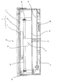
この携帯端末充電装置6は、図2〜図6に示すように、上面に携帯端末設置板7を配置した箱型の本体ケース8と、この本体ケース8内において、携帯端末設置板7の下面側に対向した状態で水平方向に可動自在に設けた充電コイル9と、この充電コイル9を携帯端末設置板7の下面側に対向して水平方向に移動させる駆動部10とを備えている。
As shown in FIGS. 2 to 6, the mobile
以下、各部について詳細に説明する。 Hereinafter, each part will be described in detail.
先ず、携帯端末設置板7について説明する。
First, the portable
この携帯端末設置板7は、図6に示すように、表面板11、中板12、裏面板13を重合させた構成となっている。
As shown in FIG. 6, the portable
また、表面板11と裏面板13は、合成樹脂によって形成され、さらに中板12は、セラミックによって形成されている。つまり、充電コイル9からの磁束が携帯端末15方向に通過できるような構成となっている。
The
駆動部10は、充電コイル9を、携帯端末15の受電コイル(図示せず)の位置まで移動させる。
The
次に、充電コイル9部分について説明する。
Next, the
充電コイル9は、図4、図5から理解されるように、リード線を円環状に複数回巻きつけることによって構成されており、その外周側と、下面側は、合成樹脂製の保持体16によって覆われた状態で保持されている。
As is understood from FIGS. 4 and 5, the
また、この保持体16の下面には、図6に示すように、前記充電コイル9の下方に向けて延長された支持脚17が合成樹脂にて一体的に形成されている。
Further, as shown in FIG. 6,
また、この支持脚17の下面と、この支持脚17の下方に配置した金属製の支持板18の上面との間には、0.3ミリの隙間を設けているので、通常状態においては、充電コイル9の移動時に、支持脚17の下面が支持板18の上面に接触することはない。
In addition, since a gap of 0.3 mm is provided between the lower surface of the
このように、本実施の形態では、充電コイル9の下方に支持脚17が設けられた構成としているのである。
Thus, in this Embodiment, it is set as the structure by which the
なお、支持板18の下方には、制御基板19、本体ケース8の下面板20が配置されており、この支持板18の下面と、下面板20の上面との間には、制御基板19を貫通した支持体21を設けている。
A
次に、駆動部10について説明する。
Next, the
駆動部10は、図4、図5に示すように、X軸方向駆動軸22と、Y軸方向駆動軸23とを有し、X軸方向駆動軸22と、Y軸方向駆動軸23のそれぞれの中間部分は、保持体16の充電コイル保持部外において、この保持体16に係合させている。
As shown in FIGS. 4 and 5, the
つまり、保持体16には、X軸方向駆動軸22が貫通する貫通孔(図示せず)と、Y軸方向駆動軸23が貫通する貫通孔24とが、上下に所定間隔をおき、クロスした状態で設けられており、そこにX軸方向駆動軸22と、Y軸方向駆動軸23が貫通することで、係合状態となっているのである。
That is, in the holding
また、X軸方向駆動軸22の一端側には、ウォームホイール25が設けられ、一端には、ギア26が、他端にも、ギア26が設けられている。ウォームホイール25はウォーム27に係合し、このウォーム27はモータ28に連結されている。
A
また、両側のギア26は、それぞれ歯車板29に係合している。
The
このため、モータ28を駆動すれば、ウォーム27が回転し、それによってウォームホイール25がX軸方向駆動軸22とともに、X軸方向に移動する。これにより、充電コイル9がX軸方向に移動することとなる。
For this reason, when the
また、Y軸方向駆動軸23の一端側には、ウォームホイール30が設けられ、一端には、ギア31が、他端にも、ギア31が設けられている。
A
そして、ウォームホイール30はウォーム32に係合し、このウォーム32はモータ33に連結されている。
The
また、両側のギア31は、それぞれ歯車板34に係合している。
The
このため、モータ33を駆動すれば、ウォーム32が回転し、それによってウォームホイール30がY軸方向駆動軸23とともに、Y軸方向に移動する。これにより、充電コイル9がY軸方向に移動することとなる。
For this reason, when the
なお、図4に示す35は、充電コイル9に通電するためのフレキシブル配線であり、このフレキシブル配線35の端部は、上述した支持脚17の側面に固定されている。
Note that
以上のような構成において、携帯端末充電装置6は、自動車のアクセサリーオフ信号を検出した状態では、充電コイル9を図4〜図6に示すように、本体ケース8の中央に移動させる。
In the configuration as described above, the portable
また、図2に示すように、本体ケース8の携帯端末設置板7上に携帯端末15を置いていない状態では、誤って携帯端末設置板7上に手をついてしまう状況が発生することもある。この場合、携帯端末設置板7に過重がかかった状態となる。
In addition, as shown in FIG. 2, when the
そこで、本実施の形態では、充電コイル9を図4〜図6に示すように、本体ケース8の中央に移動させることにより、上述した過重を、充電コイル9、保持体16、支持脚17、支持板18によって支えることができる。
Therefore, in the present embodiment, as shown in FIGS. 4 to 6, the charging
このように、携帯端末設置板7上への過重がかかった状態では、携帯端末設置板7はわずかながら下方に湾曲するが、その状態で、充電コイル9、保持体16、支持脚17も下方に移動し、支持脚17の下面が支持板18の上面に当接することになる。
As described above, when the mobile
その結果、上記過重は、携帯端末設置板7、充電コイル9、保持体16、支持脚17を介して支持板18で支え、これにより携帯端末設置板7及び充電コイル9の損傷を抑制することができる。
As a result, the excessive weight is supported by the
なお、本実施の形態では、過重に対する強度を高めるために、支持板18の下面側を、支持体21を介して本体ケース8の下面板20に支持する構成としている。
In the present embodiment, the lower surface side of the
また、このような過重が取り除かれれば、携帯端末設置板7は上方へと弾性復帰し、充電コイル9、保持体16もX軸方向駆動軸22、Y軸方向駆動軸23の弾性復帰で上方復帰するので、支持脚17の下面は支持板18の上面上に隙間を持って配置された状態となる。このため、以降の充電コイル9移動時の障害となることはない。
Further, when such excessive weight is removed, the mobile
図7は、本発明の一実施の形態に係る無接点充電システムの構成を示すブロック図である。無接点充電システムは、電子機器4、車両制御部70、携帯端末充電装置6、携帯端末15を備えている。
FIG. 7 is a block diagram showing a configuration of a contactless charging system according to an embodiment of the present invention. The contactless charging system includes an
先ず、電子機器4について説明する。
First, the
ディスプレイ41は、カーナビゲーション映像を含む映像を表示し、ラジオ受信部42は、ラジオの放送波を受信及び復調して、音声出力部44に出力する。また、ディスプレイ41は、入力部としてのタッチパネルを備えていても良い。
The
制御部43は、所定のプログラムに基づいて、種々の演算を行って、電子機器4の各部を制御する。
The
音声出力部44は、ラジオ受信部42から出力されたラジオ放送信号、制御部43によって再生された音楽信号等を増幅し、スピーカ46に出力する。
The
通信部45は、ブルートゥース(Bluetooth(登録商標))等の近距離無線通信により、携帯端末15等の外部機器と無線通信を行う。
The
次に、携帯端末充電装置6について説明する。
Next, the portable
駆動制御部51は、モータ28及びモータ33が接続されており、モータ28及びモータ33を制御する。
The
充電駆動回路52は、充電制御部53の制御に基づいて、充電コイル9に電力を供給し、充電コイル9は、充電駆動回路52から供給される電力により磁束を発生する。
The charging
充電制御部53は、所定のプログラムに基づいて、種々の演算を行って、携帯端末充電装置6の各部を制御する。
The charging
通信部54は、充電コイル9と携帯端末15の受電コイル60とを用いたコイル間通信を行い、携帯端末15との通信を行う。
The
メモリ55は、携帯端末15の電池プロダクトナンバー(電池のメーカーに対応)、電池ID(電池の製品番号(型番)に対応)、コイル情報(コイル形状、コイル径、コイル巻き数の少なくとも1つ)、理想効率等を記憶する。メモリ55は、例えば、図8に示すようなテーブルとして、これらの情報を管理する。なお、電池プロダクトナンバー及び電池IDは、携帯端末15の電池モジュールの識別情報である。
The
次に、携帯端末15について説明する。
Next, the
受電コイル60は、リード線を円環状に複数回巻きつけることによって構成されており、携帯端末充電装置6の充電コイル9から発生した磁束によって誘起電力を発生し、これを受電電力として充電電池に出力する。
The power receiving coil 60 is configured by winding a lead wire in a plurality of times in an annular shape, and generates induced power by magnetic flux generated from the charging
充電電池61は、受電コイル60によって受電した電力を蓄え、蓄えた電力を携帯端末15の各部に供給する。
The
端末制御部62は、アプリケーション(以下、「アプリ」という)など所定のプログラムに基づいて、種々の演算を行って、携帯端末15の各部を制御する。
The
第1通信部63は、受電コイル60と携帯端末充電装置6の充電コイル9とを用いたコイル間でパケット通信を行い、携帯端末充電装置6との通信を行う。このパケットには、電池プロダクトナンバー及び電池IDが含まれる。
The
第2通信部64は、アプリを用いたブルートゥース等の近距離無線通信により、電子機器4と無線通信を行う。このアプリを用いた通信では、第2通信部64から電子機器4の通信部45に受電コイル60のコイル情報が送信される。
The
なお、通信するデータ(電池プロダクトナンバー、電池ID、およびコイル情報)は、第1通信部63、および第2通信部64のどちらで送信してもよい。
Data to be communicated (battery product number, battery ID, and coil information) may be transmitted by either the
ディスプレイ65は、映像及びテキストを表示し、操作部66は、ディスプレイに表示されたアイコンなど所定の画像領域を選択可能なタッチパネル、及び、物理キーなど、ユーザの操作指示を受け付ける。
The
画像処理部67は、入力画像情報を所定のアルゴリズムで処理し、ディスプレイ65に表示させる。
The
報知部68は、音、光、振動などに所定の合図を予め対応付け、音、光、振動などによってユーザに所定の合図を報知する。
The
なお、車両制御部70は、電子機器4と携帯端末充電装置6とそれぞれ車載LANであるCAN(Controller Area Network)バスで接続されており、電子機器4及び携帯端末充電装置6を含む自動車1の各部を制御する。
The
次に、上述した携帯端末充電装置6における充電制御部53の動作について、図9を用いて説明する。
Next, operation | movement of the
ステップ(以下、「ST」と省略する)101では、充電制御部53は、アクセサリーオン信号を検出した状態において、携帯端末15を検出する。
In step (hereinafter abbreviated as “ST”) 101, charging
ST102では、充電制御部53は、車両制御部70を介して電子機器4との通信を開始し、電子機器4が近距離無線通信によって取得した携帯端末15の情報を電子機器4から取得したか否かを判定し、取得できた(YES)場合には、ST103に移行し、取得できない(NO)場合には、ST105に移行する。
In ST102, charging
ST103では、充電制御部53は、取得した携帯端末15の情報から電池プロダクトナンバー、ID毎に携帯端末15の受電コイルのコイル形状、コイル径、コイル巻き数等のコイル情報をメモリ55に記憶させる。
In ST103, the charging
ST104では、充電制御部53は、充電コイル9のコイル情報、及び、携帯端末15の受電コイルのコイル情報等に基づいて、理論上最大となる給電効率(以下、「理想効率」という)を算出し、算出した理想効率を電池プロダクトナンバー及びIDに対応付けてメモリ55に記憶させる。
In ST104, the charging
ST105では、充電制御部53は、携帯端末15を検索し、給電効率の算出が可能か否かを判定する。この判定は、探索した携帯端末15の電池プロダクトナンバー及びIDがメモリ55に記憶されているか否かによって行われる。給電効率の算出が可能である(YES)場合、ST109に移行し、給電効率の算出が不可能(NO)である場合、ST106に移行する。
In ST105, the charging
なお、この時、充電制御部53は、電子機器4を使って、ユーザが携帯端末15の情報(電池プロダクトナンバー、ID毎に携帯端末15の受電コイルのコイル形状、コイル径、コイル巻き数等)を入力できるようにしてもよい。
At this time, the charging
例えば、電子機器4の制御部43が携帯端末15の情報を入力するアプリを動作させ、ディスプレイ41のタッチパネルからユーザが操作入力するようにする。
For example, the
ST106では、充電制御部53は、導電性異物を正しく検出することができないと判断し、その状態においても充電を行うかユーザに問い合わせる。このとき、例えば、図10Aに示すようなテキスト画面を電子機器4のディスプレイ41及び携帯端末15のディスプレイ65に表示させる。ユーザが充電を指示した(YES)場合、ST107において、充電制御部53は、充電を開始する。一方、ユーザが充電を指示しない(NO)場合、ST108において、充電制御部53は、充電を行わない。このとき、例えば、図10Bに示すようなテキスト画面を電子機器4のディスプレイ41及び携帯端末15のディスプレイ65に表示させ、充電を停止する。
In ST106, the charging
ST109では、充電制御部53は、充電を開始し、充電コイル9と携帯端末15の受電コイル60とを用いたコイル間通信を行い、携帯端末15における受電電力情報を取得する。
In ST109, the charging
ST110では、充電制御部53は、携帯端末15における受電電力情報と、充電電力とに基づいて、充電中の給電効率を算出し、ST111では、充電中の給電効率がメモリ55に記憶された理想効率に対して10%以上低下しているか否かを判定し、低下している(YES)場合には、ST113に移行し、低下していない(NO)場合には、ST112に移行する。
In ST110, the charging
ST112では、充電制御部53は、200ms待機して、ST109に戻る。
In ST112, charging
ST113では、充電制御部53は、導電性異物を検出したと判断し、例えば、図10Cに示すようなテキスト画面を電子機器4のディスプレイ41及び携帯端末15のディスプレイ65に表示させる。
In ST113, the charging
なお、ここでは、充電中の給電効率が理想効率に対して10%以上低下した場合に導電性異物を検出したと判断するものとして説明したが、導電性異物を検出するための割合は10%に限らず、適宜設定可能である。 Here, the description has been made assuming that the conductive foreign matter is detected when the power supply efficiency during charging is reduced by 10% or more with respect to the ideal efficiency. However, the ratio for detecting the conductive foreign matter is 10%. Not limited to this, it can be set as appropriate.
このように、本実施の形態によれば、携帯端末充電装置6が携帯端末15の受電コイル60のコイル情報を取得し、受電コイル60のコイル情報に基づいて、理想効率を算出し、携帯端末15へ充電中の給電効率が理想効率に対して低下した割合から導電性異物を検出する。これにより、携帯端末毎に異なる受電コイルを用いた充電であっても、導電性異物を精度良く検出することができ、導電性異物の発熱を回避し、安全性を向上させることができる。
As described above, according to the present embodiment, the mobile
また、本実施の形態によれば、携帯端末15の受電コイル60のコイル情報を携帯端末15と電子機器4との間の近距離無線通信によって送信し、電子機器4と携帯端末充電装置6との間の車載LANであるCANバスによって送信する。これにより、携帯端末充電装置6が近距離無線通信に対応していなくても、既存のCANバスを介して携帯端末15の情報を送信することができる。
Moreover, according to this Embodiment, the coil information of the receiving coil 60 of the
また、本実施の形態によれば、携帯端末充電装置6が携帯端末15の受電コイル60のコイル情報を電池のプロダクトナンバー及び電池IDに対応付けて記憶する。これにより、様々な携帯端末の情報を記憶しておけば、自動車の所有者以外の同乗者の携帯端末を充電する際にも、導電性異物を精度良く検出することができる。
Moreover, according to this Embodiment, the portable
なお、本実施の形態では、携帯端末15の情報を、近距離無線通信を介して電子機器4に送信し、電子機器4からCANバスを介して携帯端末充電装置6に送信するものとして説明した。しかし、本発明はこれに限らず、携帯端末15と携帯端末充電装置6との間で近距離無線通信を介して直接送信してもよい。
In the present embodiment, the information of the
また、本実施の形態では、図10に示すようなテキスト画面を電子機器4のディスプレイ41及び携帯端末15のディスプレイ65に表示する場合について説明したが、報知部68が報知してもよい。
Further, in the present embodiment, the case where the text screen as shown in FIG. 10 is displayed on the
また、本実施の形態では、携帯端末15から取得した電池プロダクトナンバー、ID、コイル情報、理想効率をメモリ55に記憶するものとして説明したが、これらの情報をメモリ55に予め記憶しておいてもよい。
In the present embodiment, the battery product number, ID, coil information, and ideal efficiency acquired from the
また、本実施の形態では、携帯端末15が電池プロダクトナンバー及び電池IDを第1通信部63から送信し、コイル情報を第2通信部64から送信する場合について説明したが、本発明はこれに限らず、電池プロダクトナンバー、電池ID及びコイル情報を第1通信部63及び第2の通信部64のいずれから送信してもよい。すなわち、これらの情報を携帯端末充電装置6へ送信する手段は特に問わない。
In the present embodiment, the case where the
さらに、本実施の形態では、給電効率を用いて導電性異物を検出しているが、先行文献(例えばJP 2011−211760 2011.10.20)に記載されているように受電コイル60の通電情報(電流及び電力など)を用いた導電性異物の検出にも適用可能である。 Further, in the present embodiment, the conductive foreign matter is detected by using the power feeding efficiency, but the energization information of the power receiving coil 60 is described as described in the prior literature (for example, JP 2011-111760 2011.10.20). The present invention can also be applied to the detection of conductive foreign matter using (current, power, etc.).
<発明の一態様の概要>
続いて、本発明にかかる一態様の概要を記載する。<Outline of One Embodiment of Invention>
Then, the outline | summary of one aspect | mode concerning this invention is described.
態様1は、被充電機器に無接点による充電を行う無接点充電装置であって、電力が供給されて磁束を発生する充電コイルと、前記被充電機器の受電コイルの特性を示すコイル情報に基づく、前記受電コイルの通電情報から導電性異物を検出する充電制御手段と、を具備する無接点充電装置。 Aspect 1 is a non-contact charging device that performs non-contact charging to a device to be charged, based on a charging coil that generates a magnetic flux when power is supplied, and coil information that indicates characteristics of a power receiving coil of the device to be charged. And a charge control means for detecting conductive foreign matter from the energization information of the power receiving coil.
態様2は、前記充電制御手段は、前記被充電機器への理想給電効率に対して、前記被充電機器への充電中の給電効率が低下した割合から導電性異物を検出する、態様1に記載の無接点充電装置。
態様3は、自装置と車載LANによって接続された電子機器に前記被充電機器から無線通信を用いて送信された前記コイル情報を、前記電子機器から取得する通信手段を具備する、態様2に記載の無接点充電装置。
態様4は、自装置と通信接続された電子機器は、前記コイル情報の操作入力が可能であり、前記電子機器から前記コイル情報を取得する通信手段を具備する、態様1に記載の無接点充電装置。
態様5は、前記コイル情報は、コイル形状、コイル径、コイル巻き数の少なくとも1つ以上である、態様1に記載の無接点充電装置。
態様6は、態様1から態様4のいずれかに記載の無接点充電装置が車内に設置された車両。
態様7は、無接点充電装置から供給された電力を受電する受電コイルと、前記受電コイルの特性を示すコイル情報を送信する通信手段と、を具備する被充電機器。
態様8は、被充電機器への充電中の給電効率を算出するステップと、前記被充電機器の受電コイルの特性を示すコイル情報に基づく、前記被充電機器への理想給電効率に対して、算出された前記給電効率が低下した割合から導電性異物を検出するステップと、をコンピュータに実行させるためのプログラム。
態様9は、受電コイルの特性を示すコイル情報を取得するステップと、取得された前記コイル情報を送信するステップと、をコンピュータに実行させるためのプログラム。
態様10は、被充電機器に無接点による充電を行う無接点充電装置であって、前記被充電機器の受電コイルの特性を示すコイル情報を記憶する記憶手段と、前記記憶手段に前記コイル情報が記憶されていない被充電機器に対して、充電不可であることを報知する充電制御手段と、を具備する無接点充電装置。 A tenth aspect is a non-contact charging device that performs non-contact charging on a device to be charged, the storage unit storing coil information indicating the characteristics of the power receiving coil of the device to be charged, and the coil information stored in the storage unit. A contactless charging apparatus comprising: charge control means for notifying that a device to be charged that is not stored is not charged.
態様11は、被充電機器に無接点による充電を行う無接点充電装置であって、前記被充電機器の受電コイルの特性を示すコイル情報を記憶する記憶手段と、前記記憶手段に前記コイル情報が記憶されていない被充電機器に対して、充電を行わないように制御する充電制御手段と、を具備する無接点充電装置。
態様12は、被充電機器の受電コイルの特性を示すコイル情報を記憶するステップと、前記コイル情報が記憶されていない被充電機器に対して、充電不可であることを報知するステップと、をコンピュータに実行させるためのプログラム。
態様13は、被充電機器の受電コイルの特性を示すコイル情報を記憶するステップと、前記コイル情報が記憶されていない被充電機器に対して、充電を行わないように制御するステップと、をコンピュータに実行させるためのプログラム。 According to a thirteenth aspect, the steps of storing coil information indicating the characteristics of the receiving coil of the device to be charged and controlling the device to be charged not to store the coil information so as not to be charged are performed. A program to make it run.
態様14は、被充電機器に無接点による充電を行う無接点充電装置であって、電力が供給されて磁束を発生する充電コイルと、前記被充電機器の電池モジュールの識別情報に対応付けて、前記被充電機器の受電コイルの特性を示すコイル情報を記憶する記憶手段と、前記記憶手段に記憶された前記コイル情報に基づく、前記被充電機器への理想給電効率に対して、前記被充電機器への充電中の給電効率が低下した割合から導電性異物を検出する充電制御手段と、を具備する無接点充電装置。 Aspect 14 is a non-contact charging device that performs non-contact charging on a device to be charged, and is associated with identification information of a charging coil that is supplied with electric power to generate magnetic flux and a battery module of the device to be charged, A storage unit that stores coil information indicating characteristics of a power receiving coil of the device to be charged, and an ideal power supply efficiency to the device to be charged based on the coil information stored in the storage unit. A non-contact charging device comprising: charge control means for detecting conductive foreign matter from a rate at which power feeding efficiency during charging of the battery is reduced.
態様15は、前記記憶手段は、前記電池モジュールの識別情報に対応付けた前記コイル情報を予め記憶している、態様14に記載の無接点充電装置。
態様16は、前記被充電機器から前記電池モジュールの識別情報及び前記コイル情報を取得する通信手段を具備し、前記記憶手段は、前記通信手段によって取得された前記電池モジュールの識別情報及び前記コイル情報を記憶する、態様14に記載の無接点充電装置。
態様17は、被充電機器の電池モジュールの識別情報に対応付けて、前記被充電機器の受電コイルの特性を示すコイル情報を記憶するステップと、記憶された前記コイル情報に基づく、前記被充電機器への理想給電効率に対して、前記被充電機器への充電中の給電効率が低下した割合から導電性異物を検出するステップと、をコンピュータに実行させるためのプログラム。
2013年3月29日出願の特願2013−071694の日本出願、2013年4月1日出願の特願2013−075929の日本出願、2013年4月1日出願の特願2013−075930の日本出願、及び、2013年4月1日出願の特願2013−075932の日本出願に含まれる明細書、図面及び要約書の開示内容は、すべて本願に援用される。 Japanese application for Japanese Patent Application No. 2013-071694 filed on March 29, 2013, Japanese application for Japanese Patent Application No. 2013-075929 filed on April 1, 2013, Japanese application for Japanese Patent Application No. 2013-075930 filed on April 1, 2013 The disclosure of the specification, drawings, and abstract contained in the Japanese application of Japanese Patent Application No. 2013-075932 filed on April 1, 2013 is incorporated herein by reference.
本発明にかかる無接点充電システムは、導電性異物の検知精度を向上させ、安全性を高めるのに有用である。 The contactless charging system according to the present invention is useful for improving the detection accuracy of conductive foreign substances and improving safety.
1 自動車
2 インストルメントパネル
3 ハンドル
4 電子機器
5 センターコンソール
6 携帯端末充電装置
7 携帯端末設置板
8 本体ケース
9 充電コイル
10 駆動部
11 表面板
12 中板
13 裏面板
15 携帯端末
16 保持体
17 支持脚
18 支持板
19 制御基板
20 下面板
21 支持体
22 X軸方向駆動軸
23 Y軸方向駆動軸
24 貫通孔
25、30 ウォームホイール
26、31 ギア
27、32 ウォーム
28、33 モータ
29、34 歯車板
35 フレキシブル配線
41、65 ディスプレイ
42 ラジオ受信部
43 制御部
44 音声出力部
45、54 通信部
46 スピーカ
51 駆動制御部
52 充電駆動回路
53 充電制御部
55 メモリ
60 受電コイル
61 充電電池
62 端末制御部
63 第1通信部
64 第2通信部
66 操作部
67 画像処理部
68 報知部
70 車両制御部DESCRIPTION OF SYMBOLS 1
Claims (4)
表示部を有するカーナビゲーション装置と、
センターコンソールに配置され前記被充電機器に充電を行う無接点充電装置と、を備えた無接点充電システムであって、
前記カーナビゲーション装置は、
前記被充電機器の受電コイルのコイル形状、コイル径、コイル巻き数の少なくとも1つ以上を示すコイル情報を前記被充電機器から無線通信によって取得し、
さらに、前記カーナビゲーション装置は前記コイル情報を車載LANで前記無接点充電装置に送信し、
前記無接点充電装置は、
前記被充電機器に電力を供給する充電コイルを有し、さらに、
前記被充電機器と前記充電コイルとの間の導電性異物を検出するため
前記コイル情報に応じて理想給電効率を算出し、
前記被充電機器の充電中の給電効率と前記理想給電効率の割合から前記導電性異物を検出し、
前記カーナビゲーション装置に備えられた前記表示部に前記導電性異物の検出に関する表示を出力する、
無接点充電システム。 A device to be charged ,
A car navigation device having a display unit;
A non-contact charging system provided with a non-contact charging device arranged on a center console and charging the device to be charged ,
The car navigation device includes:
Coil information indicating at least one of a coil shape, a coil diameter, and a coil winding number of a power receiving coil of the charged device is acquired from the charged device by wireless communication,
Furthermore, the car navigation device transmits the coil information to the contactless charging device via an in-vehicle LAN,
The contactless charging device is:
Has a charging coil for supplying power to the target charging device, further,
For detecting conductive objects between the charging coil and the target charging device
Calculate ideal power supply efficiency according to the coil information,
The conductive foreign matter is detected from the power supply efficiency during charging of the device to be charged and the ratio of the ideal power supply efficiency,
Outputting a display relating to the detection of the conductive foreign matter to the display unit provided in the car navigation device;
Contactless charging system .
タッチパネルを有するカーナビゲーション装置と、A car navigation device having a touch panel;
センターコンソールに配置され前記被充電機器に充電を行う無接点充電装置と、を備えた無接点充電システムであって、A non-contact charging system provided with a non-contact charging device arranged on a center console and charging the device to be charged,
前記カーナビゲーション装置は、The car navigation device includes:
前記被充電機器の受電コイルのコイル形状、コイル径、コイル巻き数の少なくとも1つ以上を示すコイル情報をユーザによる前記タッチパネルの操作入力によって取得し、Coil information indicating at least one of a coil shape, a coil diameter, and the number of coil turns of a power receiving coil of the device to be charged is acquired by an operation input of the touch panel by a user;
さらに、前記カーナビゲーション装置は前記コイル情報を車載LANで前記無接点充電装置に送信し、Furthermore, the car navigation device transmits the coil information to the contactless charging device via an in-vehicle LAN,
前記無接点充電装置は、The contactless charging device is:
前記被充電機器に電力を供給する充電コイルを有し、さらに、A charging coil for supplying power to the device to be charged;
前記被充電機器と前記充電コイルとの間の導電性異物を検出するためTo detect conductive foreign matter between the device to be charged and the charging coil
前記コイル情報に応じて理想給電効率を算出し、Calculate ideal power supply efficiency according to the coil information,
前記被充電機器の充電中の給電効率と前記理想給電効率の割合から前記導電性異物を検出し、The conductive foreign matter is detected from the power supply efficiency during charging of the device to be charged and the ratio of the ideal power supply efficiency,
前記カーナビゲーション装置に備えられた表示部に前記導電性異物の検出に関する表示を出力する、Outputting a display related to the detection of the conductive foreign matter on a display unit provided in the car navigation device;
無接点充電システム。Contactless charging system.
請求項2に記載の無接点充電システム。 The car navigation device has installed an application for the operation input of the coil information.
The contactless charging system according to claim 2 .
請求項1または2に記載の無接点充電システム。 The contactless charging device controls to stop charging when the conductive foreign matter is detected,
The contactless charging system according to claim 1 or 2 .
Applications Claiming Priority (9)
| Application Number | Priority Date | Filing Date | Title |
|---|---|---|---|
| JP2013071694 | 2013-03-29 | ||
| JP2013071694 | 2013-03-29 | ||
| JP2013075929 | 2013-04-01 | ||
| JP2013075932 | 2013-04-01 | ||
| JP2013075932 | 2013-04-01 | ||
| JP2013075929 | 2013-04-01 | ||
| JP2013075930 | 2013-04-01 | ||
| JP2013075930 | 2013-04-01 | ||
| PCT/JP2014/001845 WO2014156193A1 (en) | 2013-03-29 | 2014-03-28 | Contactless charging device, device to be charged, vehicle equipped with contactless charging device and program |
Publications (2)
| Publication Number | Publication Date |
|---|---|
| JPWO2014156193A1 JPWO2014156193A1 (en) | 2017-02-16 |
| JP6233725B2 true JP6233725B2 (en) | 2017-11-22 |
Family
ID=51623204
Family Applications (1)
| Application Number | Title | Priority Date | Filing Date |
|---|---|---|---|
| JP2015508094A Active JP6233725B2 (en) | 2013-03-29 | 2014-03-28 | Contactless charging system |
Country Status (3)
| Country | Link |
|---|---|
| US (1) | US20160056661A1 (en) |
| JP (1) | JP6233725B2 (en) |
| WO (1) | WO2014156193A1 (en) |
Families Citing this family (7)
| Publication number | Priority date | Publication date | Assignee | Title |
|---|---|---|---|---|
| DE102015213981A1 (en) * | 2015-07-24 | 2017-01-26 | Conti Temic Microelectronic Gmbh | Detection of a foreign body in an electromagnetic field, in particular with the aid of an NFC chip |
| EP3493363B1 (en) * | 2016-07-29 | 2020-07-01 | Sony Semiconductor Solutions Corporation | Power-supplying device |
| EP3346581B1 (en) * | 2017-01-04 | 2023-06-14 | LG Electronics Inc. | Wireless charger for mobile terminal in vehicle |
| US11689065B2 (en) * | 2019-02-15 | 2023-06-27 | Honda Motor Co., Ltd. | System and methods for charging a device |
| KR20210014906A (en) * | 2019-07-31 | 2021-02-10 | 삼성전자주식회사 | Method for controlling wireless transmit power and electronic device including the same |
| DE102019132815A1 (en) * | 2019-12-03 | 2021-06-10 | Paragon Gmbh & Co. Kgaa | Device for the wireless transmission of electrical energy |
| CN112727717B (en) * | 2020-12-31 | 2022-04-22 | Oppo广东移动通信有限公司 | Drive device and charging stand |
Family Cites Families (7)
| Publication number | Priority date | Publication date | Assignee | Title |
|---|---|---|---|---|
| JP2005252612A (en) * | 2004-03-03 | 2005-09-15 | Sony Corp | System, module, and method for radio communication, and module holder |
| JP2012139010A (en) * | 2010-12-27 | 2012-07-19 | Nec Tokin Corp | Non-contact power transmission system |
| CN103348558B (en) * | 2011-01-20 | 2016-04-27 | 株式会社东芝 | Semiconductor equipment, power transfer apparatus, power receiving apparatus, charging system, wireless communication system and charging method |
| JP5713714B2 (en) * | 2011-02-10 | 2015-05-07 | キヤノン株式会社 | Power supply apparatus and control method |
| WO2013011905A1 (en) * | 2011-07-15 | 2013-01-24 | 三洋電機株式会社 | Charging stand, battery pack and charging stand, and battery pack |
| WO2013031025A1 (en) * | 2011-09-02 | 2013-03-07 | 富士通株式会社 | Power relay |
| JP5321718B1 (en) * | 2012-06-21 | 2013-10-23 | パナソニック株式会社 | Contactless charging system |
-
2014
- 2014-03-28 JP JP2015508094A patent/JP6233725B2/en active Active
- 2014-03-28 WO PCT/JP2014/001845 patent/WO2014156193A1/en active Application Filing
- 2014-03-28 US US14/780,597 patent/US20160056661A1/en not_active Abandoned
Also Published As
| Publication number | Publication date |
|---|---|
| JPWO2014156193A1 (en) | 2017-02-16 |
| US20160056661A1 (en) | 2016-02-25 |
| WO2014156193A1 (en) | 2014-10-02 |
Similar Documents
| Publication | Publication Date | Title |
|---|---|---|
| JP6233725B2 (en) | Contactless charging system | |
| JP6398087B2 (en) | Portable terminal charger and car using it | |
| JP6411166B2 (en) | Wireless charging control method according to smart key position | |
| JP2009148108A (en) | Vehicular non-contact charger | |
| JP2009201328A (en) | Charger and charging system | |
| KR101461101B1 (en) | Wireless power transmission apparatus for vehicle | |
| JP6364625B2 (en) | Non-contact charger, its program, and car equipped with it | |
| JP5528080B2 (en) | Power supply | |
| JPWO2015098038A1 (en) | Portable terminal charger and car equipped with it | |
| JPWO2014024480A1 (en) | Non-contact charging device, program thereof, and automobile using the same | |
| JP5229414B1 (en) | Portable terminal charger and car using it | |
| JP2014193070A (en) | Contactless charger, program and vehicle mounted with contactless charger | |
| JP6340559B2 (en) | Portable terminal charger and car using it | |
| US10069337B2 (en) | Portable terminal charging device and automobile equipped with same | |
| JP2013239009A (en) | Image display device | |
| JP2015139229A (en) | Wireless power supply device and wireless power reception device | |
| JP2014166130A (en) | Portable terminal charging apparatus and a vehicle using the same | |
| JP2014033581A (en) | Non contact charger | |
| WO2014125834A1 (en) | Contactless charging system, contactless charging device, portable device, program for same, and automobile equipped with contactless charging device | |
| JP2016077023A (en) | Contactless charger, program thereof and vehicle mounted with contactless charger | |
| JP2013243906A (en) | Portable terminal charging apparatus and vehicle using the same | |
| JP2016077024A (en) | Contactless charger, program thereof and vehicle mounted with contactless charger | |
| JP2015093581A (en) | On-vehicle dock, electronic equipment, theft detection program, theft detection method | |
| JP2013078240A (en) | Contactless power transmission device, and power transmission device and power reception device thereof | |
| KR20160050679A (en) | Wireless Charging Apparatus |
Legal Events
| Date | Code | Title | Description |
|---|---|---|---|
| A621 | Written request for application examination |
Free format text: JAPANESE INTERMEDIATE CODE: A621 Effective date: 20170203 |
|
| A131 | Notification of reasons for refusal |
Free format text: JAPANESE INTERMEDIATE CODE: A131 Effective date: 20170725 |
|
| A521 | Request for written amendment filed |
Free format text: JAPANESE INTERMEDIATE CODE: A523 Effective date: 20170921 |
|
| TRDD | Decision of grant or rejection written | ||
| A01 | Written decision to grant a patent or to grant a registration (utility model) |
Free format text: JAPANESE INTERMEDIATE CODE: A01 Effective date: 20171003 |
|
| A61 | First payment of annual fees (during grant procedure) |
Free format text: JAPANESE INTERMEDIATE CODE: A61 Effective date: 20171012 |
|
| R151 | Written notification of patent or utility model registration |
Ref document number: 6233725 Country of ref document: JP Free format text: JAPANESE INTERMEDIATE CODE: R151 |
|
| S111 | Request for change of ownership or part of ownership |
Free format text: JAPANESE INTERMEDIATE CODE: R313113 |
|
| S531 | Written request for registration of change of domicile |
Free format text: JAPANESE INTERMEDIATE CODE: R313531 |
|
| SZ03 | Written request for cancellation of trust registration |
Free format text: JAPANESE INTERMEDIATE CODE: R313Z03 |