JP6340559B2 - Portable terminal charger and car using it - Google Patents
Portable terminal charger and car using it Download PDFInfo
- Publication number
- JP6340559B2 JP6340559B2 JP2015522548A JP2015522548A JP6340559B2 JP 6340559 B2 JP6340559 B2 JP 6340559B2 JP 2015522548 A JP2015522548 A JP 2015522548A JP 2015522548 A JP2015522548 A JP 2015522548A JP 6340559 B2 JP6340559 B2 JP 6340559B2
- Authority
- JP
- Japan
- Prior art keywords
- mobile terminal
- charging
- detection
- coil
- charging coil
- Prior art date
- Legal status (The legal status is an assumption and is not a legal conclusion. Google has not performed a legal analysis and makes no representation as to the accuracy of the status listed.)
- Active
Links
- 238000001514 detection method Methods 0.000 claims description 190
- 238000009434 installation Methods 0.000 claims description 76
- 239000000919 ceramic Substances 0.000 description 7
- 238000000034 method Methods 0.000 description 7
- 238000013459 approach Methods 0.000 description 6
- 238000010586 diagram Methods 0.000 description 4
- 230000007257 malfunction Effects 0.000 description 4
- 238000012790 confirmation Methods 0.000 description 3
- 229920003002 synthetic resin Polymers 0.000 description 3
- 239000000057 synthetic resin Substances 0.000 description 3
- 239000000758 substrate Substances 0.000 description 2
- 230000004907 flux Effects 0.000 description 1
- 230000006870 function Effects 0.000 description 1
- WABPQHHGFIMREM-UHFFFAOYSA-N lead(0) Chemical compound [Pb] WABPQHHGFIMREM-UHFFFAOYSA-N 0.000 description 1
- 239000002184 metal Substances 0.000 description 1
- 230000000149 penetrating effect Effects 0.000 description 1
- 230000002093 peripheral effect Effects 0.000 description 1
- 238000004804 winding Methods 0.000 description 1
Images


Classifications
-
- H—ELECTRICITY
- H02—GENERATION; CONVERSION OR DISTRIBUTION OF ELECTRIC POWER
- H02J—CIRCUIT ARRANGEMENTS OR SYSTEMS FOR SUPPLYING OR DISTRIBUTING ELECTRIC POWER; SYSTEMS FOR STORING ELECTRIC ENERGY
- H02J7/00—Circuit arrangements for charging or depolarising batteries or for supplying loads from batteries
- H02J7/0042—Circuit arrangements for charging or depolarising batteries or for supplying loads from batteries characterised by the mechanical construction
- H02J7/0044—Circuit arrangements for charging or depolarising batteries or for supplying loads from batteries characterised by the mechanical construction specially adapted for holding portable devices containing batteries
-
- H—ELECTRICITY
- H02—GENERATION; CONVERSION OR DISTRIBUTION OF ELECTRIC POWER
- H02J—CIRCUIT ARRANGEMENTS OR SYSTEMS FOR SUPPLYING OR DISTRIBUTING ELECTRIC POWER; SYSTEMS FOR STORING ELECTRIC ENERGY
- H02J50/00—Circuit arrangements or systems for wireless supply or distribution of electric power
- H02J50/10—Circuit arrangements or systems for wireless supply or distribution of electric power using inductive coupling
-
- H—ELECTRICITY
- H02—GENERATION; CONVERSION OR DISTRIBUTION OF ELECTRIC POWER
- H02J—CIRCUIT ARRANGEMENTS OR SYSTEMS FOR SUPPLYING OR DISTRIBUTING ELECTRIC POWER; SYSTEMS FOR STORING ELECTRIC ENERGY
- H02J50/00—Circuit arrangements or systems for wireless supply or distribution of electric power
- H02J50/90—Circuit arrangements or systems for wireless supply or distribution of electric power involving detection or optimisation of position, e.g. alignment
Description
本発明は、携帯電話などの携帯端末を充電するための携帯端末充電装置と、それを用いた自動車に関するものである。 The present invention relates to a mobile terminal charging device for charging a mobile terminal such as a mobile phone, and an automobile using the same.
携帯電話等の携帯端末はその機能が極めて高くなり、それにつれて電力消費も大きくなっている。 The functions of mobile terminals such as mobile phones have become extremely high, and the power consumption has increased accordingly.
したがって、自動車内を含め、各所で充電が行えることが求められてきているが、近年の傾向として、ケーブルを使わずに、いわゆる非接触充電が行えるものが脚光を浴びている。 Accordingly, it has been demanded that charging can be performed in various places including inside the automobile. However, as a trend in recent years, what can perform so-called non-contact charging without using a cable has been in the spotlight.
このような要望に応える携帯端末充電装置としては、以下のようなものが提案されている。 The following devices have been proposed as portable terminal charging devices that meet such demands.
すなわち、上面に携帯端末設置板を配置した本体ケースと、この本体ケース内において、前記携帯端末設置板の下面側に対向して可動自在に設けた充電コイルと、この充電コイルを前記携帯端末設置板の下面側に対向して移動させる駆動手段と、この駆動手段と前記充電コイルに接続した制御手段とを備えた構成となっていた。 That is, a main body case in which a mobile terminal installation plate is arranged on the upper surface, a charging coil that is movably provided facing the lower surface side of the mobile terminal installation plate in the main body case, and the charging coil is installed in the mobile terminal The driving means moved to face the lower surface side of the plate, and the driving means and control means connected to the charging coil were provided.
また、前記携帯端末設置板には、この携帯端末設置板上面に設置される携帯端末の位置を検出する複数の検出コイルが、設けられていた(例えば、下記特許文献1)。
The mobile terminal installation board is provided with a plurality of detection coils for detecting the position of the mobile terminal installed on the upper surface of the mobile terminal installation board (for example,
上記従来例においては、携帯端末を携帯端末設置板の上面に置けば、置かれた携帯端末の位置は検出コイルによって検出され、その検出場所に充電コイルが移動し、その状態で充電が行えるので、効率的な充電が行える。 In the above conventional example, if the portable terminal is placed on the upper surface of the portable terminal installation plate, the position of the placed portable terminal is detected by the detection coil, the charging coil moves to the detection location, and charging can be performed in that state. Efficient charging.
しかしながら、携帯端末を携帯端末設置板の上面においた状態から移動させてしまった場合や、携帯端末を携帯端末設置板の上面すれすれの位置を移動させてしまった場合には、効率的な充電が行えないことがある。 However, when the mobile terminal is moved from a state where it is placed on the top surface of the mobile terminal installation board, or when the mobile terminal is moved to a position where the top surface of the mobile terminal installation board passes, efficient charging is performed. There are things you can't do.
すなわち、上述のような場合、検出コイルは携帯端末が携帯端末設置板の上面に初めに置かれた場所や、携帯端末設置板の上面に初めに接近した場所を、携帯端末位置として検出し、そこに充電コイルを移動させてしまうのである。 That is, in the case as described above, the detection coil detects the place where the mobile terminal is first placed on the top surface of the mobile terminal installation board or the location where the mobile terminal first approaches the top surface of the mobile terminal installation board as the mobile terminal position, The charging coil is moved there.
しかし、実際には携帯端末は、その後、携帯端末設置板上面の他の位置に移動しており、この状態では、携帯端末位置と充電コイル位置がずれた状態となり、その結果として効率的な充電が行えなくなるのである。 However, in practice, the mobile terminal has subsequently moved to another position on the top surface of the mobile terminal installation plate, and in this state, the mobile terminal position and the charging coil position are shifted, resulting in efficient charging. Can not be done.
そこで、本発明は、効率的な充電が行えるようにすることを目的とするものである。 Therefore, an object of the present invention is to enable efficient charging.
本発明の一態様は、上面に携帯端末設置板を配置した本体ケースと、携帯端末設置板に設けられるとともに、この携帯端末設置板上面に設置される携帯端末の位置を検出する検出手段と、本体ケース内において、携帯端末設置板の下面側に対向した状態で、可動自在に配置した充電コイルと、この充電コイルを携帯端末設置板の下面側に対向した状態で移動させる駆動手段と、この駆動手段と充電コイルに接続した制御手段とを備え、制御手段は、検出手段に携帯端末設置板上面における携帯端末の位置を複数回検出させ、前回の検出位置と、その次検出位置が同じ場合に、この検出手段が検出した前回の検出位置、または、その次の検出位置に対向する充電位置に、充電コイルを、駆動手段によって移動させ、その後充電を開始させる構成とし、これにより所期の目的を達成するものである。 One aspect of the present invention is a main body case in which a mobile terminal installation plate is arranged on the upper surface, a detection means that is provided on the mobile terminal installation plate and detects the position of the mobile terminal installed on the upper surface of the mobile terminal installation plate, In the main body case, a charging coil that is movably disposed in a state of being opposed to the lower surface side of the mobile terminal installation plate, a driving means for moving the charging coil in a state of being opposed to the lower surface side of the mobile terminal installation plate, A drive unit and a control unit connected to the charging coil, the control unit causes the detection unit to detect the position of the mobile terminal on the top surface of the mobile terminal installation plate a plurality of times, and the previous detection position and the next detection position are the same In addition, the configuration is such that the charging coil is moved by the driving means to the charging position opposite to the previous detection position detected by the detection means or the next detection position, and then charging is started. And, thereby it is to achieve the intended purpose.
上記のような構成によれば、検出手段によって携帯端末設置板上面における携帯端末の位置を複数回検出し、前回の検出位置と、その次の検出位置が同じ場合に、この検出手段が検出した前回の検出位置、または、その次の検出位置に対向する充電位置に、充電コイルを、駆動手段によって移動させ、その後充電を開始させる構成としたので、実際の携帯端末位置に充電コイルを移動させることができ、その結果として、効率的な充電が行えるようになるのである。 According to the configuration as described above, the position of the mobile terminal on the top surface of the mobile terminal installation plate is detected by the detection means a plurality of times, and this detection means detects when the previous detection position and the next detection position are the same. Since the charging coil is moved by the driving means to the charging position opposite to the previous detection position or the next detection position, and then the charging is started, the charging coil is moved to the actual mobile terminal position. As a result, efficient charging can be performed.
以上のように本発明は、充電コイルを、携帯端末位置に、より正確に移動させることができる。 As described above, the present invention can move the charging coil to the mobile terminal position more accurately.
よって、効率的な充電が行えるようになる。 Therefore, efficient charging can be performed.
以下、本発明の一実施形態を、添付図面を用いて説明する。 Hereinafter, an embodiment of the present invention will be described with reference to the accompanying drawings.
(実施の形態1)
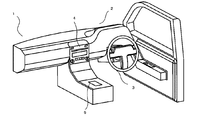
図1において、自動車1の車内2の前方にはハンドル3が設置されている。(Embodiment 1)
In FIG. 1, a
また、ハンドル3の側方には、音楽や、映像の再生と、カーナビゲーション映像を映し出す電子機器4が設置されている。
Further, on the side of the
さらに、車内2の電子機器4後方には、携帯端末充電装置5が設置されている。
Furthermore, a portable
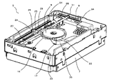
この携帯端末充電装置5は、図2〜図6に示すように、上面に携帯端末設置板6を配置した箱型の本体ケース7と、この本体ケース7内において、前記携帯端末設置板6の下面側に対向した状態で水平方向に可動自在に設けた充電コイル8と、この充電コイル8を前記携帯端末設置板6の下面側に対向して水平方向に移動させる駆動手段9と、この駆動手段9と前記充電コイル8に接続した制御手段(図9の10)とを備えている。
As shown in FIGS. 2 to 6, the portable
以下、各部について詳細に説明する。 Hereinafter, each part will be described in detail.
先ず、携帯端末設置板6について説明する。
First, the portable
この携帯端末設置板6は、図6に示すように、表面板11、中板12、裏面板13を重合させた構成となっている。
As shown in FIG. 6, the portable
また、表面板11と裏面板13は、合成樹脂によって形成され、さらに中板12は、セラミックによって形成されている。つまり、充電コイル8からの磁束が、この携帯端末設置板6を、携帯端末15方向に通過できるような構成となっている。
The
また、中板12の表面には、図9の位置検出コイル14が設けられている。
Further, the
この位置検出コイル14は、上記特許文献1(特開2009−247194号公報)で用いられているものであり、携帯端末設置板6の上面の何れの位置に、図3のごとく携帯端末15が置かれたかを検出するものである。
This
本実施形態においては、この位置検出コイル14を用いて、携帯端末設置板6の上面のどの位置に、図3のごとく携帯端末15が置かれたかを検出し、次に駆動手段9によって充電コイル8を、前記携帯端末15の充電コイル(図示せず)位置にまで移動させる構成となっている。
In the present embodiment, the
次に、充電コイル8部分について説明する。
Next, the
充電コイル8は、図4、図5から理解されるように、リード線を円環状に複数回巻きつけることによって構成されており、その外周側と、下面側は、合成樹脂製の保持体16によって覆われた状態で保持されている。
As is understood from FIGS. 4 and 5, the
また、この保持体16の下面には、図6のごとく、前記充電コイル8の下方に向けて延
長された支持脚17が、合成樹脂にて一体的に形成されている。Further, as shown in FIG. 6,
また、この支持脚17の下面と、この支持脚17の下方に配置した金属製の支持板18の上面との間には、0・3ミリの隙間を設けているので、通常状態においては、充電コイル8の移動時に、支持脚17の下面が支持板18の上面に接触することはない。
In addition, since a gap of 0.3 mm is provided between the lower surface of the
そして、以上の構成において、本実施形態では、充電コイル8の下方に支持脚17が設けられた構成としているのである。
In the above configuration, the
なお、支持板18の下方には、制御基板19、本体ケース7の下面板20が配置されており、この支持板18の下面と、下面板20の上面との間には、制御基板19を貫通した支持体21を設けている。
A
次に、駆動手段9について説明する。 Next, the drive means 9 will be described.
駆動手段9は、図4、図5に示すように、X軸方向駆動軸22と、Y軸方向駆動軸23を有し、これらのX軸方向駆動軸22と、Y軸方向駆動軸23のそれぞれの中間部分は、保持体16の充電コイル保持部外において、この保持体16に係合させている。
As shown in FIGS. 4 and 5, the drive means 9 has an X-axis
つまり、保持体16には、X軸方向駆動軸22が貫通する貫通孔(図示せず)と、Y軸方向駆動軸23が貫通する貫通孔24が、上下に所定間隔をおき、クロスした状態で設けられており、そこにX軸方向駆動軸22と、Y軸方向駆動軸23が貫通することで、係合状態となっているのである。
In other words, in the
また、X軸方向駆動軸22の一端側にはウォームホイール25が設けられ、一端には、ギア26、他端にもギア26が設けられている。
A
そして、ウォームホイール25はウォーム27に係合し、このウォーム27はモータ28に連結されている。
The
また、両側のギア26は、それぞれ歯車板29に係合している。
The
このため、モータ28を駆動すれば、ウォーム27が回転し、それによってウォームホイール25がX軸方向駆動軸22とともに、X軸方向に移動し、これにて充電コイル8がX軸方向に移動することとなる。
For this reason, when the
また、Y軸方向駆動軸23の一端側にはウォームホイール30が設けられ、一端には、ギア31、他端にもギア31が設けられている。
A
そして、ウォームホイール30はウォーム32に係合し、このウォーム32はモータ33に連結されている。
The
また、両側のギア31は、それぞれ歯車板34に係合している。
The
このため、モータ33を駆動すれば、ウォーム32が回転し、それによってウォームホイール30がY軸方向駆動軸23とともに、Y軸方向に移動し、これにて充電コイル8がY軸方向に移動することとなる。
For this reason, when the
なお、図4に示す35は充電コイル8に通電するためのフレキシブル配線であり、このフレキシブル配線35の端部は、上述した支持脚17の側面に固定されている。
4 is a flexible wiring for energizing the
また、図9に示すごとく制御手段10には、X軸モータ制御部36を介してモータ28が接続され、またY軸モータ制御部37を介してモータ33が接続されている。
Further, as shown in FIG. 9, a
また、制御手段10には、充電コイル制御部38を介して充電コイル8が接続され、さらに制御手段10には、検出用コイル制御部39を介して位置検出コイル14が接続されている。
In addition, the charging
以上のような構成において、本実施形態では、電源スイッチ40をOFF操作(図10のS1)にすると、充電コイル8を図4〜図6に示すように、本体ケース7の中央(以下A点と称す)に移動させ(図10のS2)、その後電源をOFF状態とする(図10のS3)。
In the configuration as described above, in this embodiment, when the power switch 40 is turned off (S1 in FIG. 10), the charging
つまり、図2のごとく、本体ケース7の携帯端末設置板6上に携帯端末15を置いていない状態では、この携帯端末設置板6は図1のごとく車内2に表出した状態となっている。
That is, as shown in FIG. 2, when the
このため、誤ってこの携帯端末設置板6上に手をついてしまう状況が発生することもあり、このときには携帯端末設置板6にとっては過重がかかった状態となる。
For this reason, a situation may occur in which a hand is accidentally touched on the portable
そこで、本実施形態では、充電コイル8を図4〜図6に示すように、本体ケース7の中央に移動させ、上述した過重を、充電コイル8、保持体16、支持脚17、支持板18によって支えるようにしているのである。
Therefore, in this embodiment, as shown in FIGS. 4 to 6, the charging
つまり、このような携帯端末設置板6上への過重がかかった状態になると、携帯端末設置板6はわずかながら下方に湾曲するが、その状態で、充電コイル8、保持体16、支持脚17も下方に移動し、支持脚17の下面が支持板18の上面に当接することになる。
In other words, when the mobile
その結果、上記過重は、携帯端末設置板6、充電コイル8、保持体16、支持脚17を介して支持板18で支え、これにより携帯端末設置板6や充電コイル8の損傷を抑制することが出来るようになる。
As a result, the excessive weight is supported by the
なお、本実施形態では、過重に対する強度を高めるために、支持板18の下面側を、支持体21を介して本体ケース7の下面板20に支持する構成としている。
In the present embodiment, the lower surface side of the
また、このような過重が取り除かれれば、携帯端末設置板6は上方へと弾性復帰し、充電コイル8、保持体16もX軸方向駆動軸22、Y軸方向駆動軸23の弾性復帰で上方復帰するので、支持脚17の下面は支持板18の上面上に隙間を持って配置された状態となる。
Further, when such excessive weight is removed, the portable
このため、以降の充電コイル8移動時の障害となることはない。
For this reason, it does not become an obstacle at the time of
また、携帯端末15の充電時には、先ずは電源スイッチ40をON状態(図10のS4)にするとともに、携帯端末設置板6の上面上に携帯端末15が置かれることになる。
When charging the
この状態になっても、本実施形態では、先ずは、制御手段10によって充電コイル8がA点に存在しているか否かの確認を行う(図10のS5)。
Even in this state, in this embodiment, first, it is confirmed by the control means 10 whether or not the charging
この確認は、X軸モータ制御部36、Y軸モータ制御部37が記憶するモータ28、33の駆動量から判別することができる。
This confirmation can be determined from the drive amounts of the
そして、充電コイル8がA点に存在していないと判断された場合には、制御手段10によって充電コイル8をA点に移動させ(図10のS6)、このA点にて充電待機状態とする(図10のS7)。
When it is determined that the charging
次に、制御手段10は、位置検出コイル14を用いて、携帯端末設置板6の上面の何れの位置に、図3のごとく携帯端末15が置かれたかを検出する(図10のS8、S9)。
Next, the control means 10 uses the
なお、携帯端末15が置かれた場所とは、実際には携帯端末15が内蔵する携帯充電コイル(図16の15a)の場所である。
The place where the
その後、制御手段10は、X軸モータ制御部36、Y軸モータ制御部37を介してモータ28、33を駆動し、検出された携帯端末15が保有する携帯充電コイル(図16の15a)位置へと充電コイル8を移動させ(図10のS10)、その後、充電コイル制御部38を介して充電を開始する(図10のS11、S12)。
Thereafter, the control means 10 drives the
また、この充電中には、上記特許文献1(特開2009−247194号公報)と同じ動作により、充電の継続が必要か否か(充電完了したか、否か)を判定し(図10のS13)、充電完了(満充電)すると、制御手段10は、充電動作を終了させる(図10のS14)。 Further, during this charging, it is determined whether or not the continuation of charging is necessary (whether charging is completed or not) by the same operation as that of Patent Document 1 (Japanese Patent Laid-Open No. 2009-247194) (see FIG. 10). S13) Upon completion of charging (full charge), the control means 10 ends the charging operation (S14 in FIG. 10).
また、このような充電動作が完了すると、制御手段10によって充電コイル8がA点に存在しているか否かの確認を行い(図10のS15)、その後、充電コイル8をA点に戻す(図10のS6)。
When such a charging operation is completed, the control means 10 confirms whether or not the charging
この確認は、X軸モータ制御部36、Y軸モータ制御部37が記憶するモータ28、33の駆動量から判別することができる。
This confirmation can be determined from the drive amounts of the
なお、制御手段10によって充電コイル8をA点に戻すことが出来ない場合、例えば運転中の何らかの衝撃で、X軸モータ制御部36、Y軸モータ制御部37が記憶するモータ28、33の駆動量から算出される位置と、位置検出コイル14によって測定される実位置がずれた場合には、図7、図8の動作を実行させる。
In addition, when the control means 10 cannot return the charging
つまり、制御手段10でX軸モータ制御部36、Y軸モータ制御部37を介してモータ28、33を駆動し、充電コイル8を本体ケース7内のコーナまで移動させるのである。
That is, the control means 10 drives the
このコーナ部分にはスイッチ41、42が存在しており、充電コイル8が本体ケース7内のコーナまで移動すれば、これらのスイッチ41、42が動作し、これにより制御手段10は充電コイル8が初期値に移動したと判定する。
そして、この状態では、X軸モータ制御部36、Y軸モータ制御部37によるモータ28、33の動作量も初期値とし、ここから再度位置制御を行うようにしているのである。
In this state, the operation amounts of the
以上のように本実施形態では、充電動作終了時、制御手段10によって充電コイル8をA点に戻すようにしており、この部分について、さらに詳細に説明を行う。
As described above, in the present embodiment, the charging
このA点は上述のごとく、本体ケース7の中央部分であると説明してきたが、このA点と、位置検出コイル14とは、以下に説明する関係が保たれていれば、本体ケース7の中央部分でなくてもよい。
As described above, the point A has been described as being the central portion of the
先ず、位置検出コイル14について説明する。
First, the
この位置検出コイル14は、携帯端末設置板6を構成するセラミック製の中板12に設けられているが、詳細には図11のごとく、中板12の表面側には、X軸方向の位置を検出する位置検出コイル14Aが設けられ、また中板12の裏面側には、Y軸方向の位置を検出する位置検出コイル14Bが設けられている。
The
なお、位置検出コイル14Aと位置検出コイル14Bは、携帯端末設置板6を構成するセラミック製の中板12を介して直交する状態となっている。
In addition, the
X軸方向の位置を検出する位置検出コイル14Aは、図11、図12から理解されるように、携帯端末設置板6を構成するセラミック製の中板12の長手方向に、複数の位置検出コイル14Aa、14Ab、14Ac、14Adを所定間隔ごとに配置することにより構成されている。
As can be understood from FIGS. 11 and 12, the
これらの位置検出コイル14Aa、14Ab、14Ac、14Adは図12に示すごとく、長方形のループ形状となっているが、それらの短辺方向の1/3の寸法をずらした状態で、配置されている。 These position detection coils 14Aa, 14Ab, 14Ac, and 14Ad have a rectangular loop shape as shown in FIG. 12, but are arranged in a state in which the size of 1/3 in the short side direction is shifted. .
したがって、位置検出コイル14Aaの図12の下辺と、位置検出コイル14Adの上辺は重なった状態となっている。 Therefore, the lower side of FIG. 12 of the position detection coil 14Aa and the upper side of the position detection coil 14Ad are overlapped.
そして、このような状態で、携帯端末設置板6を構成するセラミック製の中板12の長手方向に、複数の位置検出コイル14Aa、14Ab、14Ac、14Adが規則正しく配置されている。
In such a state, a plurality of position detection coils 14Aa, 14Ab, 14Ac, and 14Ad are regularly arranged in the longitudinal direction of the ceramic
これに対して、Y軸方向の位置を検出する位置検出コイル14Bは、図11、図13から理解されるように、携帯端末設置板6を構成するセラミック製の中板12の短手方向に、複数の位置検出コイル14Ba、14Bb、14Bc、14Bdを所定間隔ごとに配置することにより構成されている。
On the other hand, the position detection coil 14B for detecting the position in the Y-axis direction is in the short direction of the ceramic
これらの位置検出コイル14Ba、14Bb、14Bc、14Bdは図13に示すごとく、長方形のループ形状となっているが、それらの短辺方向の1/3の寸法をずらした状態で、配置されている。 These position detection coils 14Ba, 14Bb, 14Bc, and 14Bd have a rectangular loop shape as shown in FIG. 13, but are arranged in a state in which the dimension of 1/3 in the short side direction is shifted. .
したがって、位置検出コイル14Baの図13の右辺と、位置検出コイル14Bdの左辺は重なった状態となっている。 Therefore, the right side in FIG. 13 of the position detection coil 14Ba and the left side of the position detection coil 14Bd are in an overlapping state.
そして、このような状態で、携帯端末設置板6を構成するセラミック製の中板12の短手方向に、複数の位置検出コイル14Ba、14Bb、14Bc、14Bdが規則正しく配置されている。
In such a state, a plurality of position detection coils 14Ba, 14Bb, 14Bc, and 14Bd are regularly arranged in the short-side direction of the ceramic
次に、図14を用いて、位置検出コイル14Ba、14Bb、14Bc、14Bdと、上記本体ケース7の中央部分であるA点との関係について説明する。
Next, the relationship between the position detection coils 14Ba, 14Bb, 14Bc, and 14Bd and the point A that is the central portion of the
なお、この図14では、位置検出コイル14Ba、14Bb、14Bc、14Bdの区別をしやすいように、図14の上下にもずらした状態としているが、実際の状態は図13のようになっている。 In FIG. 14, the position detection coils 14Ba, 14Bb, 14Bc, and 14Bd are shifted up and down in FIG. 14 so that they can be easily distinguished, but the actual state is as shown in FIG. .
図14において、aは位置検出コイル14Baの短辺の中心を通る中心線、bは位置検
出コイル14Bbの短辺の中心を通る中心線、cは位置検出コイル14Bcの短辺の中心を通る中心線、dは位置検出コイル14Bdの短辺の中心を通る中心線である。In FIG. 14, a is a center line passing through the center of the short side of the position detection coil 14Ba, b is a center line passing through the center of the short side of the position detection coil 14Bb, and c is a center passing through the center of the short side of the position detection coil 14Bc. A line d is a center line passing through the center of the short side of the position detection coil 14Bd.
ここで重要なことは、この図14に示すごとく、上記A点にて待機中の充電コイル8の中心点が、何れの位置検出コイル14Ba、14Bb、14Bc、14Bdの中心線a、b、c、dとも重ならない状態となっていることである。
What is important here is that, as shown in FIG. 14, the center point of the charging
つまり、充電終了後、充電コイル8は、何れの位置検出コイル14Ba、14Bb、14Bc、14Bdの中心線a、b、c、dとも重ならない(位置検出コイル14Ba、14Bb、14Bc、14Bの中心線a、b、c、dとは外れた部分)に移動され、このA位置にて待機するようにしているのである(図10のS2、またはS7)。
That is, after the end of charging, the charging
なお、本実施形態においては、携帯端末設置板6の上面に、携帯端末15が置かれたか否かの検出(図10のS8)は、位置検出コイル14Ba、14Bb、14Bc、14Bd側で行うので、これらの位置検出コイル14Ba、14Bb、14Bc、14Bdの中心線a、b、c、dとは重ならない位置を、上記充電コイル8の待機位置であるA位置としている。
In the present embodiment, detection of whether or not the
勿論、携帯端末設置板6の上面に、携帯端末15が置かれたか否かの検出(図10のS8)を、14Aa、14Ab、14Ac、14Ad側で行うこととしても良く、その場合には、これらの位置検出コイル14Aa、14Ab、14Ac、14Adの中心線a、b、c、dとは重ならない位置を、上記充電コイル8の待機位置であるA位置とする。
Of course, the detection (S8 in FIG. 10) of whether or not the
以上の構成を基に、動作説明をさらに詳細に行うと、携帯端末15の充電のために、電源スイッチ40をON状態(図10のS4)にすると、上述のごとく、制御手段10によって充電コイル8がA点に存在しているか否かの確認を行う(図10、図15のS5)。
Based on the above configuration, the operation will be described in more detail. When the power switch 40 is turned on (S4 in FIG. 10) for charging the
この確認は、X軸モータ制御部36、Y軸モータ制御部37が記憶するモータ28、33の駆動量から判別することができる。
This confirmation can be determined from the drive amounts of the
そして、充電コイル8がA点に存在していないと判断された場合には、制御手段10によって充電コイル8をA点に移動させ(図10、図15のS6)、このA点にて充電待機状態とする(図10、図15のS7)。
When it is determined that the charging
次に、制御手段10は、位置検出コイル14を用いて、携帯端末設置板6の上面の何れの位置に、図3のごとく携帯端末15が置かれたかを検出する(図10、図15のS8、S9)。
Next, the control means 10 uses the
なお、携帯端末15が置かれた場所とは、実際には携帯端末15が内蔵する携帯充電コイル(図16の15a)の場所である。
The place where the
この点について、図14、図15を用いて詳細に説明すると、位置検出コイル14を用いて、携帯端末設置板6の上面の何れの位置に、図3のごとく携帯端末15が置かれたかを検出するときには、図9の検出用コイル制御部39から、位置検出コイル14Ba、14Bb、14Bc、14Bdに、順次1MHzのパルス信号を供給し(図15のS81)、その時に、携帯端末15の携帯充電コイル(図16の15a)からのエコー信号があるか、否かによって、制御手段10は、携帯端末設置板6の上面の何れの位置に、図3のごとく携帯端末15が置かれたか否かを判定する(図15のS82、S83)。
This point will be described in detail with reference to FIGS. 14 and 15. The
なお、このときに位置検出コイル14Ba、14Bb、14Bc、14Bdで捕らえた
エコー信号は、図9のメモリ10aに一時的に記憶される。Note that the echo signals captured by the position detection coils 14Ba, 14Bb, 14Bc, and 14Bd at this time are temporarily stored in the
さて、携帯端末15の携帯充電コイル(図16の15a)は、よく知られているように、充電前には、1MHzにて共振するようになっているので、上述した位置検出コイル14Ba、14Bb、14Bc、14Bdに、順次1MHzのパルス信号が出力されたときには、大きなエコー信号を発することとなり、それを位置検出コイル14Ba、14Bb、14Bc、14Bdが捕らえ、これによって携帯端末設置板6の上面の何れの位置に、図3のごとく携帯端末15が置かれたことが検出される。
As is well known, the portable charging coil (15a in FIG. 16) of the
図16は、携帯端末設置板6の上面で、位置検出コイル14Bbの中心線b上に、携帯端末15の携帯充電コイル15aが置かれた状態を示し、位置検出コイル14Ba、14Bb、14Bc、14Bdで捕らえるエコー信号は、位置検出コイル14Bbが最も大きなものであることが判る。
FIG. 16 shows a state where the
これに対して、図17は 携帯端末設置板6の上面で、位置検出コイル14Bb、14Bcの中心線b、c間上に、携帯端末15の携帯充電コイル15aが置かれた状態を示し、位置検出コイル14Ba、14Bb、14Bc、14Bdで捕らえるエコー信号は、位置検出コイル14Bb、14Bcが、14Ba、14Bdよりも大きいが、図16のエコー信号よりも小さなものとなる。
On the other hand, FIG. 17 shows a state where the
また、携帯端末15の種類や、その状態(例えば裏面側にカバーがある、シールが貼られている)によっては、前記携帯端末15の携帯充電コイル15aからのエコー信号は図17と同じように小さなものとなってしまうことがあり、このようなものでも、携帯端末設置板6の上面の何れの位置に、図3のごとく携帯端末15が置かれたことが検出できるように、前記エコー信号の判定レベルを下げている。
Moreover, the echo signal from the
しかし、このようにエコー信号の判定レベルを下げると、充電コイル8からのエコー信号によって誤動作を起こしてしまう虞がある。
However, if the determination level of the echo signal is lowered in this way, the echo signal from the charging
図18は、充電コイル8の待機位置A点が、例えば位置検出コイル14Bbの中心線b下となった場合を示し、このときには充電コイル8からのエコー信号は、位置検出コイル14Ba、14Bb、14Bc、14Bdで捕らえた場合、位置検出コイル14Bbがもっとも大きなものであること、およびそのレベルが高いものであることが判る。
FIG. 18 shows a case where the standby position A of the charging
そして、このような状態になると、位置検出コイル14Ba、14Bb、14Bc、14Bdで捕らえたエコー信号が、携帯充電コイル15aによるものか、充電コイル8によるものかが判定できなくなり、その結果として以降の動作に誤動作が発生する虞がある。
In such a state, it becomes impossible to determine whether the echo signal captured by the position detection coils 14Ba, 14Bb, 14Bc, 14Bd is from the
つまり、上述のごとく、携帯端末15が、携帯端末設置板6の上面の何れの位置に置かれたか、またはその種類や、その状態(例えば裏面側にカバーがある、シールが貼られている)によっては、前記携帯端末15の携帯充電コイル15aからのエコー信号は図17のとうに小さなものとなってしまうことがあり、このようなものでも、携帯端末設置板6の上面の何れの位置に、図3のごとく携帯端末15が置かれたことが検出できるように、前記エコー信号の判定レベルを下げている。
That is, as described above, the
しかしながら、このように判定レベルを下げると、図18のように充電コイル8からのエコー信号のレベルが高いものになると、制御手段10は、携帯端末設置板6の上面に携帯端末15が置かれていないにも関らず、携帯端末設置板6の上面に携帯端末15が置かれたと判断し、以降の動作を実行してしまう。
However, when the determination level is lowered in this way, when the level of the echo signal from the charging
これが、誤動作の原因で、本実施形態では、これを防止するために上述のごとく、充電終了後に、充電コイル8が待機するA位置は、何れの位置検出コイル14Ba、14Bb、14Bc、14Bdの中心線a、b、c、dとも重ならない位置(位置検出コイル14Ba、14Bb、14Bc、14Bの中心線a、b、c、dとは外れた位置)とした。
This is a cause of malfunction. In the present embodiment, as described above, in order to prevent this, the A position where the charging
その結果、充電コイル8からのエコー信号は、図14のごとく、何れの位置検出コイル14Ba、14Bb、14Bc、14Bで捕らえたものも小さく(図17よりも十分小さく)することが出来る。
As a result, as shown in FIG. 14, the echo signal from the charging
したがって、携帯端末設置板6の上面に携帯端末15が置かれたか、否かの判定を間違うことは無く、以降の誤動作を起こしてしまうことがなくなるのである
そして、このように携帯端末設置板6の上面に携帯端末15が置かれたことが判定されると、その後は、制御手段10により、検出用コイル制御部39を動作させ、位置検出コイル14Aa、14Ab、14Ac、14Adと、位置検出コイル14Ba、14Bb、14Bc、14Bdにパルス信号を供給し、携帯端末15の携帯充電コイル15aを特定する(図15のS9)。Therefore, it is not wrong to determine whether or not the
そして、検出用コイル制御部39が、この携帯端末15の携帯充電コイル15aの位置が特定できると、制御手段10は、X軸モータ制御部36、Y軸モータ制御部37を介してモータ28、33を駆動し、検出された携帯端末15が保有する携帯充電コイル15a位置へと充電コイル8を移動させ(図10、図15のS10)、その後、充電コイル制御部38を介して充電を開始する(図10のS11、S12)。
Then, when the detection
すなわち、検出用コイル制御部39が携帯充電コイル15aの位置を特定した後、制御手段10が充電コイル8を移動させるようにすることが好ましい。なぜなら、充電コイル8が、待機位置であるA位置以外の場所にあると、検出用コイル制御部39が携帯充電コイル15aの位置を精度良く検出できないからである。
That is, it is preferable that the control means 10 moves the charging
次に、本実施形態における最も大きな特徴点について、図19〜図21を用いて説明する。 Next, the largest feature point in the present embodiment will be described with reference to FIGS.
本実施形態の最も大きな特徴点は、検出手段として用いた位置検出コイル14によって携帯端末設置板6上面における携帯端末15の位置を複数回検出し、前回の検出位置と、その次(次回と表現する)の検出位置が同じ場合に、この位置検出コイル14が検出した前記前回の検出位置、または次回の検出位置に対向する充電位置に、充電コイル8を、駆動手段として用いたモータ28、33によって移動させ、その後充電を開始させる構成したことである。
The biggest feature point of the present embodiment is that the position of the
本実施形態の位置検出コイル14は、携帯端末15が携帯端末設置板6上面に接近、または置かれた場合に、上述のごとく、携帯端末15の有無を検出することができるようになっている(図19のS1)。
The
すなわち、本実施形態では、上述のごとく、携帯端末15の携帯充電コイル(図16の15a)は、よく知られているように、充電前には、1MHzにて共振するようになっているので、上述した位置検出コイル14Ba、14Bb、14Bc、14Bdに、順次1MHzのパルス信号が出力されたときには、大きなエコー信号を発することとなり、それを位置検出コイル14Ba、14Bb、14Bc、14Bdが捕らえ、これによって携帯端末設置板6の上面の何れの位置に、図3のごとく携帯端末15が置かれたことが検出されるようになっている。
That is, in this embodiment, as described above, the portable charging coil (15a in FIG. 16) of the
図20、図21は位置検出コイル14によって携帯端末15が検出された状態を示すものである。
20 and 21 show a state in which the
この内、図20は、携帯端末15を携帯端末設置板6の上面に、通常の状態で置いた状態を示している。
Among these, FIG. 20 shows a state where the
つまり、時間(t0)のときに、携帯端末15が携帯端末設置板6の上面に接近し、位置検出コイル14によって携帯端末15が地点(x0)で検出され、その後、時間(t1)のときに地点(x1)で、携帯端末15が携帯端末設置板6の上面に置かれている。
That is, at time (t0), the mobile terminal 15 approaches the upper surface of the mobile
したがって、その後、所定時間ごとに携帯端末15の置かれた地点を、位置検出コイル14によって検出しても、検出地点は地点(x1)となっている。
Therefore, after that, even if the point where the
つまり、時間(t1)、時間(t2)、時間(t3)、時間(t4)、時間(t5)、時間(t6)においても、検出地点は地点(x1)となっている。 That is, the detection point is the point (x1) also at time (t1), time (t2), time (t3), time (t4), time (t5), and time (t6).
これに対して、図21は、携帯端末15を携帯端末設置板6の上面に置く動作を実行している状況で、携帯端末15が、携帯端末設置板6上面に一端置かれたが、その後継続的に移動したり、携帯端末15が、携帯端末設置板6上面を接近した状態で移動させられたりしている状態を示している。
On the other hand, FIG. 21 shows a situation where the
つまり、時間(t0)のときに、携帯端末15が携帯端末設置板6の上面に接近し、位置検出コイル14によって携帯端末15が地点(x0)で検出され、その後も、携帯端末15が携帯端末設置板6の上面を移動している。
That is, at time (t0), the mobile terminal 15 approaches the upper surface of the mobile
したがって、その後、所定時間ごとに携帯端末15の置かれた地点を、位置検出コイル14によって検出すると、時間(t1)のときには地点(x1)、時間(t2)のときには地点(x2)、時間(t3)のときには地点(x3)、時間(t4)のときには地点(x4)、時間(t5)のときには地点(x4)、時間(t6)のときには地点(x4)となっている。
Accordingly, when the
すなわち、この図21では、時間(t4)のときに地点(x4)に携帯端末15が置かれた状況を示している。
That is, FIG. 21 shows a situation in which the
このような図20でも図21でも、位置検出コイル14で、携帯端末15を初めて検出した状態で、直ちにその場所に、充電コイル8を、モータ28、33によって移動させ、その後、充電を開始させると、結論として、携帯端末15と充電コイル8の位置がずれた状態となり、効率的な充電が行えなくなる。
20 and FIG. 21, with the
そこで、本実施形態では、検出手段として用いた位置検出コイル14によって携帯端末設置板6上面における携帯端末15の位置を複数回検出し、前回の検出位置と、その次(次回と表現する)の検出位置が同じ場合に、この位置検出コイル14が検出した前記前回の検出位置、または次回の検出位置に対向する充電位置に、充電コイル8を、駆動手段として用いたモータ28、33によって移動させ、その後充電を開始させる構成した。
Therefore, in the present embodiment, the position of the
具体的には、図20の場合には、携帯端末15が携帯端末設置板6上面に接近した場合(図20のt0)に、上述のごとく、携帯端末15の有無と、位置検出を行う(図19のS1、S2)。
Specifically, in the case of FIG. 20, when the mobile terminal 15 approaches the upper surface of the mobile terminal installation board 6 (t0 in FIG. 20), the presence / absence of the
次に、制御手段10は、前回の検出位置と、次回の検出位置が同じか否かの判断を行う(図19のS3)。 Next, the control means 10 determines whether or not the previous detection position is the same as the next detection position (S3 in FIG. 19).
図20では、(t0)において、位置検出コイル14によって携帯端末15が地点(x0)で検出されたばかりで、前回の検出地点が無いので、このときには携帯端末15の位置が安定したとはならず、再度S2に戻る(図19のS4、S2)。
In FIG. 20, at (t0), the
次に、時間(t1)で再び位置検出が行われ、このときには(x1)の位置が検出され、再び前回の検出位置と、次回の検出位置が同じか否かの判断を行う(図19のS2、S3)。 Next, position detection is performed again at time (t1). At this time, the position (x1) is detected, and it is determined again whether the previous detection position is the same as the next detection position (FIG. 19). S2, S3).
しかしながら、このときには前回検出位置は(x0)で、今回の検出位置は(x1)であるので、再びこのときには携帯端末15の位置が安定したとはならず、再度S2に戻る(図19のS4、S2)。
However, since the previous detection position is (x0) and the current detection position is (x1) at this time, the position of the
次に、時間(t2)で再び位置検出が行われ、このときには(x1)の位置が検出され、再び前回の検出位置と、次回の検出位置が同じか否かの判断を行う(図19のS2、S3)。 Next, position detection is performed again at time (t2). At this time, the position (x1) is detected, and it is again determined whether the previous detection position is the same as the next detection position (FIG. 19). S2, S3).
そして、このときには前回検出位置は(x1)で、今回の検出位置も(x1)であるので、充電コイル8を検出位置は(x1)に移動し、充電を開始する(図19のS4、S5)。
At this time, since the previous detection position is (x1) and the current detection position is also (x1), the charging
なお、この図20では、その後も、位置検出を(t2〜t6)まで行っているが、充電を開始した時点で、この位置検出は終了としても良い。 In FIG. 20, the position detection is performed from (t2 to t6) after that, but the position detection may be ended when charging is started.
これに対して、図21の状態では、携帯端末15が携帯端末設置板6上面に接近した場合(図21のt0)に、上述のごとく、携帯端末15の有無と、位置検出を行う(図19のS1、S2)。
On the other hand, in the state of FIG. 21, when the mobile terminal 15 approaches the upper surface of the mobile terminal installation plate 6 (t0 in FIG. 21), the presence / absence of the
次に、制御手段10は、前回の検出位置と、次回の検出位置が同じか否かの判断を行う(図19のS3)。 Next, the control means 10 determines whether or not the previous detection position is the same as the next detection position (S3 in FIG. 19).
図21では、(t0)において、位置検出コイル14によって携帯端末15が地点(x0)で検出されたばかりで、前回の検出地点が無いので、このときには携帯端末15の位置が安定したとはならず、再度S2に戻る(図19のS4、S2)。
In FIG. 21, the
次に、時間(t1)で再び位置検出が行われ、このときには(x1)の位置が検出され、再び前回の検出位置と、次回の検出位置が同じか否かの判断を行う(図19のS2、S3)。 Next, position detection is performed again at time (t1). At this time, the position (x1) is detected, and it is determined again whether the previous detection position is the same as the next detection position (FIG. 19). S2, S3).
しかしながら、このときには前回検出位置は(x0)で、今回の検出位置は(x1)であるので、再びこのときには携帯端末15の位置が安定したとはならず、再度S2に戻る(図19のS4、S2)。
However, since the previous detection position is (x0) and the current detection position is (x1) at this time, the position of the
次に、時間(t2)で再び位置検出が行われ、このときには(x2)の位置が検出され、再び前回の検出位置と、次回の検出位置が同じか否かの判断を行う(図19のS2、S3)。 Next, position detection is performed again at time (t2). At this time, the position (x2) is detected, and it is determined again whether the previous detection position is the same as the next detection position (FIG. 19). S2, S3).
しかしながら、このときには前回検出位置は(x2)で、今回の検出位置は(x1)で
あるので、再びこのときには携帯端末15の位置が安定したとはならず、再度S2に戻る(図19のS4、S2)。However, since the previous detection position is (x2) and the current detection position is (x1) at this time, the position of the
次に、時間(t3)で再び位置検出が行われ、このときには(x3)の位置が検出され、再び前回の検出位置と、次回の検出位置が同じか否かの判断を行う(図19のS2、S3)。 Next, position detection is performed again at time (t3). At this time, the position (x3) is detected, and it is determined again whether the previous detection position is the same as the next detection position (FIG. 19). S2, S3).
しかしながら、このときには前回検出位置は(x2)で、今回の検出位置は(x3)であるので、再びこのときには携帯端末15の位置が安定したとはならず、再度S2に戻る(図19のS4、S2)。
However, since the previous detection position is (x2) and the current detection position is (x3) at this time, the position of the
次に、時間(t4)で再び位置検出が行われ、このときには(x4)の位置が検出され、再び前回の検出位置と、次回の検出位置が同じか否かの判断を行う(図19のS2、S3)。 Next, position detection is performed again at time (t4). At this time, the position (x4) is detected, and it is again determined whether or not the previous detection position is the same as the next detection position (FIG. 19). S2, S3).
しかしながら、このときには前回検出位置は(x3)で、今回の検出位置は(x4)であるので、再びこのときには携帯端末15の位置が安定したとはならず、再度S2に戻る(図19のS4、S2)。
However, since the previous detection position is (x3) and the current detection position is (x4) at this time, the position of the
次に、時間(t5)で再び位置検出が行われ、このときには(x4)の位置が検出され、再び前回の検出位置と、次回の検出位置が同じか否かの判断を行う(図19のS2、S3)。 Next, position detection is performed again at time (t5). At this time, the position (x4) is detected, and it is determined again whether the previous detection position is the same as the next detection position (FIG. 19). S2, S3).
そして、このときには前回検出位置は(x4)で、今回の検出位置も(x4)であるので、充電コイル8を検出位置は(x4)に移動し、充電を開始する(図19のS4、S5)。
At this time, since the previous detection position is (x4) and the current detection position is also (x4), the charging
なお、この図20では、その後も、位置検出を(t6)まで行っているが、充電を開始した時点で、この位置検出は終了としても良い。 In FIG. 20, the position detection is performed up to (t6) after that, but the position detection may be ended when charging is started.
以上のごとく、本実施形態では、制御手段10で、検出手段として用いた位置検出コイル14によって携帯端末設置板6上面における携帯端末15の位置を複数回検出し、前回の検出位置と、その次(次回と表現している)の検出位置が同じ場合に、この位置検出コイル14が検出した前記前回の検出位置、または次回の検出位置に対向する充電位置に、充電コイル8を、駆動手段として用いたモータ28、33によって移動させ、その後充電を開始させる構成した。
As described above, in the present embodiment, the
このため、携帯端末15と充電コイル8の位置がずれた状態で充電が行われることは無く、効率的な充電が行える。
For this reason, charging is not performed in a state where the positions of the
なお、位置の比較は、前回の検出位置と、今回の検出位置の比較だけでなく、前回の検出位置と、今回の検出位置、または次回の検出位置を比較しても良い。 The comparison of the positions may be performed not only by comparing the previous detection position with the current detection position, but also by comparing the previous detection position with the current detection position or the next detection position.
以上のごとく本発明においては、効率的な充電が行えるようになるのである。 As described above, in the present invention, efficient charging can be performed.
したがって、車載用や家庭用の携帯端末充電装置としての活用が期待されるものとなる。 Therefore, it is expected to be used as a mobile terminal charging device for in-vehicle use or home use.
1 自動車
2 車内
3 ハンドル
4 電子機器
5 携帯端末充電装置
6 携帯端末設置板
7 本体ケース
8 充電コイル
9 駆動手段
10 制御手段
10a メモリ
11 表面板
12 中板
13 裏面板
14 位置検出コイル
14Aa,14Ab,14Ac,14Ad,14Ba,14Bb,14Bc,14Bd
位置検出コイル
15 携帯端末
15a 携帯充電コイル
16 保持体
17 支持脚
18 支持板
19 制御基板
20 下面板
21 支持体
22 X軸方向駆動軸
23 Y軸方向駆動軸
24 貫通孔
25 ウォームホイール
26 ギア
27 ウォーム
28 モータ
29 歯車板
30 ウォームホイール
31 ギア
32 ウォーム
33 モータ
34 歯車板
35 フレキシブル配線
36 X軸モータ制御部
37 Y軸モータ制御部
38 充電コイル制御部
39 検出用コイル制御部
40 電源スイッチ
41 スイッチ
42 スイッチ
DESCRIPTION OF
Claims (6)
この携帯端末設置板上面に設置される携帯端末の位置を検出する検出部と、
前記本体ケース内において、前記携帯端末設置板の下面側に対向した状態で、可動自在に配置した充電コイルと、
この充電コイルを前記携帯端末設置板の下面側に対向した状態で移動させる駆動部と、この駆動部と前記充電コイルに接続した制御部とを備え、
前記制御部は、前記検出部に携帯端末設置板上面における携帯端末の位置を複数回検出させ、前回の検出位置と、その次の検出位置が同じ場合に、この検出部が検出した前記前回の検出位置、または、その次の検出位置に対向する充電位置に、前記充電コイルを、前記駆動部によって移動させ、その後充電を開始する携帯端末充電装置。A body case with a mobile terminal installation plate on the top surface
A detection unit for detecting the position of the mobile terminal installed on the upper surface of the mobile terminal installation plate;
In the main body case, in a state facing the lower surface side of the mobile terminal installation plate, a charging coil movably disposed,
A drive unit that moves the charging coil in a state of facing the lower surface side of the mobile terminal installation plate, and a control unit connected to the drive unit and the charging coil,
The control unit causes the detection unit to detect the position of the mobile terminal on the upper surface of the mobile terminal installation plate a plurality of times, and when the previous detection position and the next detection position are the same, the previous detection detected by the detection unit A portable terminal charging apparatus that moves the charging coil to a detection position or a charging position opposite to a next detection position by the driving unit and then starts charging.
The mobile terminal charging device according to claim 1, wherein the position of the mobile terminal is detected again when the previous detection position is different from the next detection position.
Applications Claiming Priority (3)
| Application Number | Priority Date | Filing Date | Title |
|---|---|---|---|
| JP2013124365 | 2013-06-13 | ||
| JP2013124365 | 2013-06-13 | ||
| PCT/JP2014/003125 WO2014199638A1 (en) | 2013-06-13 | 2014-06-12 | Mobile terminal charger and vehicle equipped with same |
Publications (2)
| Publication Number | Publication Date |
|---|---|
| JPWO2014199638A1 JPWO2014199638A1 (en) | 2017-02-23 |
| JP6340559B2 true JP6340559B2 (en) | 2018-06-13 |
Family
ID=52021950
Family Applications (1)
| Application Number | Title | Priority Date | Filing Date |
|---|---|---|---|
| JP2015522548A Active JP6340559B2 (en) | 2013-06-13 | 2014-06-12 | Portable terminal charger and car using it |
Country Status (3)
| Country | Link |
|---|---|
| US (1) | US9859730B2 (en) |
| JP (1) | JP6340559B2 (en) |
| WO (1) | WO2014199638A1 (en) |
Families Citing this family (3)
| Publication number | Priority date | Publication date | Assignee | Title |
|---|---|---|---|---|
| JP6178976B2 (en) * | 2013-05-31 | 2017-08-16 | パナソニックIpマネジメント株式会社 | Portable terminal charger and car using it |
| FR3059485B1 (en) * | 2016-11-29 | 2019-12-27 | Continental Automotive France | INDUCTION CHARGING DEVICE FOR A USER EQUIPMENT FOR A MOTOR VEHICLE |
| CN109149794B (en) * | 2017-06-28 | 2020-11-17 | 金宝电子工业股份有限公司 | Wireless charging system and wireless charging method |
Family Cites Families (10)
| Publication number | Priority date | Publication date | Assignee | Title |
|---|---|---|---|---|
| US5573090A (en) * | 1994-05-05 | 1996-11-12 | H. R. Ross Industries, Inc. | Raodway-powered electric vehicle system having onboard power metering and communication channel features |
| JP4788693B2 (en) * | 2007-09-26 | 2011-10-05 | セイコーエプソン株式会社 | Structure |
| JP5362330B2 (en) | 2007-12-18 | 2013-12-11 | 三洋電機株式会社 | Charging stand |
| JP2009273327A (en) * | 2008-05-10 | 2009-11-19 | Sanyo Electric Co Ltd | Battery built-in apparatus and charging cradle |
| JPWO2012081519A1 (en) * | 2010-12-15 | 2014-05-22 | 三洋電機株式会社 | Charging stand |
| US8645604B2 (en) * | 2011-03-25 | 2014-02-04 | Apple Inc. | Device orientation based docking functions |
| JP5666997B2 (en) * | 2011-06-21 | 2015-02-12 | タナシン電機株式会社 | Coil-moving contactless charger |
| JP5836080B2 (en) * | 2011-11-21 | 2015-12-24 | シャープ株式会社 | Mounting base, charging base, short-range wireless device, and position detection method |
| EP2696467A4 (en) * | 2012-02-29 | 2015-11-18 | Panasonic Ip Man Co Ltd | Charging apparatus |
| US9124124B2 (en) * | 2012-10-16 | 2015-09-01 | Ford Global Technologies, Llc | System and method for reducing interference during wireless charging |
-
2014
- 2014-06-12 JP JP2015522548A patent/JP6340559B2/en active Active
- 2014-06-12 WO PCT/JP2014/003125 patent/WO2014199638A1/en active Application Filing
-
2015
- 2015-11-24 US US14/950,974 patent/US9859730B2/en active Active
Also Published As
| Publication number | Publication date |
|---|---|
| US9859730B2 (en) | 2018-01-02 |
| US20160079782A1 (en) | 2016-03-17 |
| JPWO2014199638A1 (en) | 2017-02-23 |
| WO2014199638A1 (en) | 2014-12-18 |
Similar Documents
| Publication | Publication Date | Title |
|---|---|---|
| JP6226302B2 (en) | Non-contact charging device, program thereof, and automobile using the same | |
| JP6364625B2 (en) | Non-contact charger, its program, and car equipped with it | |
| JP6467639B2 (en) | Portable terminal charger and car equipped with it | |
| JP6178976B2 (en) | Portable terminal charger and car using it | |
| JP6398087B2 (en) | Portable terminal charger and car using it | |
| US9935488B2 (en) | Portable terminal charging apparatus and automobile having portable terminal charging apparatus mounted therein | |
| JP6340559B2 (en) | Portable terminal charger and car using it | |
| JP6706751B2 (en) | A vehicle equipped with a non-contact charging device, its program, and the non-contact charging device | |
| JP6340602B2 (en) | Portable terminal charger and car equipped with it | |
| JP5229414B1 (en) | Portable terminal charger and car using it | |
| JP2015027172A (en) | Contactless charger and vehicle having the same mounted therein | |
| JP6311132B2 (en) | Portable terminal charger and car equipped with it | |
| JP6191949B2 (en) | Non-contact charging device, program, and vehicle equipped with the non-contact charging device | |
| JP2013243906A (en) | Portable terminal charging apparatus and vehicle using the same | |
| JP2014166130A (en) | Portable terminal charging apparatus and a vehicle using the same |
Legal Events
| Date | Code | Title | Description |
|---|---|---|---|
| A621 | Written request for application examination |
Free format text: JAPANESE INTERMEDIATE CODE: A621 Effective date: 20170529 |
|
| TRDD | Decision of grant or rejection written | ||
| A01 | Written decision to grant a patent or to grant a registration (utility model) |
Free format text: JAPANESE INTERMEDIATE CODE: A01 Effective date: 20180327 |
|
| A61 | First payment of annual fees (during grant procedure) |
Free format text: JAPANESE INTERMEDIATE CODE: A61 Effective date: 20180409 |
|
| R151 | Written notification of patent or utility model registration |
Ref document number: 6340559 Country of ref document: JP Free format text: JAPANESE INTERMEDIATE CODE: R151 |
|
| S111 | Request for change of ownership or part of ownership |
Free format text: JAPANESE INTERMEDIATE CODE: R313113 |
|
| S531 | Written request for registration of change of domicile |
Free format text: JAPANESE INTERMEDIATE CODE: R313531 |
|
| SZ03 | Written request for cancellation of trust registration |
Free format text: JAPANESE INTERMEDIATE CODE: R313Z03 |