JP6233381B2 - 4-wheel drive vehicle transfer - Google Patents

4-wheel drive vehicle transfer Download PDF

Info

Publication number
JP6233381B2
JP6233381B2 JP2015210272A JP2015210272A JP6233381B2 JP 6233381 B2 JP6233381 B2 JP 6233381B2 JP 2015210272 A JP2015210272 A JP 2015210272A JP 2015210272 A JP2015210272 A JP 2015210272A JP 6233381 B2 JP6233381 B2 JP 6233381B2
Authority
JP
Japan
Prior art keywords
shaft
fork
output shaft
cam
axis
Prior art date
Legal status (The legal status is an assumption and is not a legal conclusion. Google has not performed a legal analysis and makes no representation as to the accuracy of the status listed.)
Active
Application number
JP2015210272A
Other languages
Japanese (ja)
Other versions
JP2017081318A (en
Inventor
瑞樹 今福
瑞樹 今福
Current Assignee (The listed assignees may be inaccurate. Google has not performed a legal analysis and makes no representation or warranty as to the accuracy of the list.)
Toyota Motor Corp
Original Assignee
Toyota Motor Corp
Priority date (The priority date is an assumption and is not a legal conclusion. Google has not performed a legal analysis and makes no representation as to the accuracy of the date listed.)
Filing date
Publication date
Application filed by Toyota Motor Corp filed Critical Toyota Motor Corp
Priority to JP2015210272A priority Critical patent/JP6233381B2/en
Priority to TW105134066A priority patent/TWI613103B/en
Priority to CA2946002A priority patent/CA2946002C/en
Priority to RU2016141418A priority patent/RU2647408C1/en
Priority to US15/331,148 priority patent/US10124669B2/en
Priority to MYPI2016703895A priority patent/MY173704A/en
Priority to KR1020160138321A priority patent/KR101846338B1/en
Priority to EP16195606.5A priority patent/EP3170690B1/en
Priority to PH12016000379A priority patent/PH12016000379A1/en
Priority to BR102016024863A priority patent/BR102016024863A2/en
Priority to CN201610998437.8A priority patent/CN107020952B/en
Priority to ES16195606T priority patent/ES2762898T3/en
Priority to AU2016250344A priority patent/AU2016250344B2/en
Publication of JP2017081318A publication Critical patent/JP2017081318A/en
Application granted granted Critical
Publication of JP6233381B2 publication Critical patent/JP6233381B2/en
Active legal-status Critical Current
Anticipated expiration legal-status Critical

Links

Images

Classifications

    • BPERFORMING OPERATIONS; TRANSPORTING
    • B60VEHICLES IN GENERAL
    • B60KARRANGEMENT OR MOUNTING OF PROPULSION UNITS OR OF TRANSMISSIONS IN VEHICLES; ARRANGEMENT OR MOUNTING OF PLURAL DIVERSE PRIME-MOVERS IN VEHICLES; AUXILIARY DRIVES FOR VEHICLES; INSTRUMENTATION OR DASHBOARDS FOR VEHICLES; ARRANGEMENTS IN CONNECTION WITH COOLING, AIR INTAKE, GAS EXHAUST OR FUEL SUPPLY OF PROPULSION UNITS IN VEHICLES
    • B60K17/00Arrangement or mounting of transmissions in vehicles
    • B60K17/34Arrangement or mounting of transmissions in vehicles for driving both front and rear wheels, e.g. four wheel drive vehicles
    • B60K17/344Arrangement or mounting of transmissions in vehicles for driving both front and rear wheels, e.g. four wheel drive vehicles having a transfer gear
    • BPERFORMING OPERATIONS; TRANSPORTING
    • B60VEHICLES IN GENERAL
    • B60KARRANGEMENT OR MOUNTING OF PROPULSION UNITS OR OF TRANSMISSIONS IN VEHICLES; ARRANGEMENT OR MOUNTING OF PLURAL DIVERSE PRIME-MOVERS IN VEHICLES; AUXILIARY DRIVES FOR VEHICLES; INSTRUMENTATION OR DASHBOARDS FOR VEHICLES; ARRANGEMENTS IN CONNECTION WITH COOLING, AIR INTAKE, GAS EXHAUST OR FUEL SUPPLY OF PROPULSION UNITS IN VEHICLES
    • B60K17/00Arrangement or mounting of transmissions in vehicles
    • B60K17/02Arrangement or mounting of transmissions in vehicles characterised by arrangement, location, or kind of clutch
    • BPERFORMING OPERATIONS; TRANSPORTING
    • B60VEHICLES IN GENERAL
    • B60KARRANGEMENT OR MOUNTING OF PROPULSION UNITS OR OF TRANSMISSIONS IN VEHICLES; ARRANGEMENT OR MOUNTING OF PLURAL DIVERSE PRIME-MOVERS IN VEHICLES; AUXILIARY DRIVES FOR VEHICLES; INSTRUMENTATION OR DASHBOARDS FOR VEHICLES; ARRANGEMENTS IN CONNECTION WITH COOLING, AIR INTAKE, GAS EXHAUST OR FUEL SUPPLY OF PROPULSION UNITS IN VEHICLES
    • B60K17/00Arrangement or mounting of transmissions in vehicles
    • B60K17/04Arrangement or mounting of transmissions in vehicles characterised by arrangement, location, or kind of gearing
    • B60K17/06Arrangement or mounting of transmissions in vehicles characterised by arrangement, location, or kind of gearing of change-speed gearing
    • BPERFORMING OPERATIONS; TRANSPORTING
    • B60VEHICLES IN GENERAL
    • B60KARRANGEMENT OR MOUNTING OF PROPULSION UNITS OR OF TRANSMISSIONS IN VEHICLES; ARRANGEMENT OR MOUNTING OF PLURAL DIVERSE PRIME-MOVERS IN VEHICLES; AUXILIARY DRIVES FOR VEHICLES; INSTRUMENTATION OR DASHBOARDS FOR VEHICLES; ARRANGEMENTS IN CONNECTION WITH COOLING, AIR INTAKE, GAS EXHAUST OR FUEL SUPPLY OF PROPULSION UNITS IN VEHICLES
    • B60K23/00Arrangement or mounting of control devices for vehicle transmissions, or parts thereof, not otherwise provided for
    • B60K23/08Arrangement or mounting of control devices for vehicle transmissions, or parts thereof, not otherwise provided for for changing number of driven wheels, for switching from driving one axle to driving two or more axles
    • B60K23/0808Arrangement or mounting of control devices for vehicle transmissions, or parts thereof, not otherwise provided for for changing number of driven wheels, for switching from driving one axle to driving two or more axles for varying torque distribution between driven axles, e.g. by transfer clutch
    • FMECHANICAL ENGINEERING; LIGHTING; HEATING; WEAPONS; BLASTING
    • F16ENGINEERING ELEMENTS AND UNITS; GENERAL MEASURES FOR PRODUCING AND MAINTAINING EFFECTIVE FUNCTIONING OF MACHINES OR INSTALLATIONS; THERMAL INSULATION IN GENERAL
    • F16HGEARING
    • F16H25/00Gearings comprising primarily only cams, cam-followers and screw-and-nut mechanisms
    • F16H25/18Gearings comprising primarily only cams, cam-followers and screw-and-nut mechanisms for conveying or interconverting oscillating or reciprocating motions
    • F16H25/20Screw mechanisms
    • F16H25/22Screw mechanisms with balls, rollers, or similar members between the co-operating parts; Elements essential to the use of such members
    • F16H25/2204Screw mechanisms with balls, rollers, or similar members between the co-operating parts; Elements essential to the use of such members with balls
    • FMECHANICAL ENGINEERING; LIGHTING; HEATING; WEAPONS; BLASTING
    • F16ENGINEERING ELEMENTS AND UNITS; GENERAL MEASURES FOR PRODUCING AND MAINTAINING EFFECTIVE FUNCTIONING OF MACHINES OR INSTALLATIONS; THERMAL INSULATION IN GENERAL
    • F16HGEARING
    • F16H3/00Toothed gearings for conveying rotary motion with variable gear ratio or for reversing rotary motion
    • F16H3/02Toothed gearings for conveying rotary motion with variable gear ratio or for reversing rotary motion without gears having orbital motion
    • F16H3/08Toothed gearings for conveying rotary motion with variable gear ratio or for reversing rotary motion without gears having orbital motion exclusively or essentially with continuously meshing gears, that can be disengaged from their shafts
    • F16H3/087Toothed gearings for conveying rotary motion with variable gear ratio or for reversing rotary motion without gears having orbital motion exclusively or essentially with continuously meshing gears, that can be disengaged from their shafts characterised by the disposition of the gears
    • F16H3/089Toothed gearings for conveying rotary motion with variable gear ratio or for reversing rotary motion without gears having orbital motion exclusively or essentially with continuously meshing gears, that can be disengaged from their shafts characterised by the disposition of the gears all of the meshing gears being supported by a pair of parallel shafts, one being the input shaft and the other the output shaft, there being no countershaft involved
    • FMECHANICAL ENGINEERING; LIGHTING; HEATING; WEAPONS; BLASTING
    • F16ENGINEERING ELEMENTS AND UNITS; GENERAL MEASURES FOR PRODUCING AND MAINTAINING EFFECTIVE FUNCTIONING OF MACHINES OR INSTALLATIONS; THERMAL INSULATION IN GENERAL
    • F16HGEARING
    • F16H37/00Combinations of mechanical gearings, not provided for in groups F16H1/00 - F16H35/00
    • F16H37/02Combinations of mechanical gearings, not provided for in groups F16H1/00 - F16H35/00 comprising essentially only toothed or friction gearings
    • F16H37/06Combinations of mechanical gearings, not provided for in groups F16H1/00 - F16H35/00 comprising essentially only toothed or friction gearings with a plurality of driving or driven shafts; with arrangements for dividing torque between two or more intermediate shafts
    • F16H37/065Combinations of mechanical gearings, not provided for in groups F16H1/00 - F16H35/00 comprising essentially only toothed or friction gearings with a plurality of driving or driven shafts; with arrangements for dividing torque between two or more intermediate shafts with a plurality of driving or driven shafts
    • FMECHANICAL ENGINEERING; LIGHTING; HEATING; WEAPONS; BLASTING
    • F16ENGINEERING ELEMENTS AND UNITS; GENERAL MEASURES FOR PRODUCING AND MAINTAINING EFFECTIVE FUNCTIONING OF MACHINES OR INSTALLATIONS; THERMAL INSULATION IN GENERAL
    • F16HGEARING
    • F16H63/00Control outputs from the control unit to change-speed- or reversing-gearings for conveying rotary motion or to other devices than the final output mechanism
    • F16H63/02Final output mechanisms therefor; Actuating means for the final output mechanisms
    • F16H63/04Final output mechanisms therefor; Actuating means for the final output mechanisms a single final output mechanism being moved by a single final actuating mechanism
    • FMECHANICAL ENGINEERING; LIGHTING; HEATING; WEAPONS; BLASTING
    • F16ENGINEERING ELEMENTS AND UNITS; GENERAL MEASURES FOR PRODUCING AND MAINTAINING EFFECTIVE FUNCTIONING OF MACHINES OR INSTALLATIONS; THERMAL INSULATION IN GENERAL
    • F16HGEARING
    • F16H63/00Control outputs from the control unit to change-speed- or reversing-gearings for conveying rotary motion or to other devices than the final output mechanism
    • F16H63/02Final output mechanisms therefor; Actuating means for the final output mechanisms
    • F16H63/30Constructional features of the final output mechanisms
    • F16H63/32Gear shift yokes, e.g. shift forks
    • BPERFORMING OPERATIONS; TRANSPORTING
    • B60VEHICLES IN GENERAL
    • B60KARRANGEMENT OR MOUNTING OF PROPULSION UNITS OR OF TRANSMISSIONS IN VEHICLES; ARRANGEMENT OR MOUNTING OF PLURAL DIVERSE PRIME-MOVERS IN VEHICLES; AUXILIARY DRIVES FOR VEHICLES; INSTRUMENTATION OR DASHBOARDS FOR VEHICLES; ARRANGEMENTS IN CONNECTION WITH COOLING, AIR INTAKE, GAS EXHAUST OR FUEL SUPPLY OF PROPULSION UNITS IN VEHICLES
    • B60K17/00Arrangement or mounting of transmissions in vehicles
    • B60K17/34Arrangement or mounting of transmissions in vehicles for driving both front and rear wheels, e.g. four wheel drive vehicles
    • B60K17/354Arrangement or mounting of transmissions in vehicles for driving both front and rear wheels, e.g. four wheel drive vehicles having separate mechanical assemblies for transmitting drive to the front or to the rear wheels or set of wheels
    • BPERFORMING OPERATIONS; TRANSPORTING
    • B60VEHICLES IN GENERAL
    • B60KARRANGEMENT OR MOUNTING OF PROPULSION UNITS OR OF TRANSMISSIONS IN VEHICLES; ARRANGEMENT OR MOUNTING OF PLURAL DIVERSE PRIME-MOVERS IN VEHICLES; AUXILIARY DRIVES FOR VEHICLES; INSTRUMENTATION OR DASHBOARDS FOR VEHICLES; ARRANGEMENTS IN CONNECTION WITH COOLING, AIR INTAKE, GAS EXHAUST OR FUEL SUPPLY OF PROPULSION UNITS IN VEHICLES
    • B60K23/00Arrangement or mounting of control devices for vehicle transmissions, or parts thereof, not otherwise provided for
    • B60K23/08Arrangement or mounting of control devices for vehicle transmissions, or parts thereof, not otherwise provided for for changing number of driven wheels, for switching from driving one axle to driving two or more axles
    • B60K2023/085Arrangement or mounting of control devices for vehicle transmissions, or parts thereof, not otherwise provided for for changing number of driven wheels, for switching from driving one axle to driving two or more axles automatically actuated
    • B60K2023/0858Arrangement or mounting of control devices for vehicle transmissions, or parts thereof, not otherwise provided for for changing number of driven wheels, for switching from driving one axle to driving two or more axles automatically actuated with electric means, e.g. electro-hydraulic means
    • BPERFORMING OPERATIONS; TRANSPORTING
    • B60VEHICLES IN GENERAL
    • B60YINDEXING SCHEME RELATING TO ASPECTS CROSS-CUTTING VEHICLE TECHNOLOGY
    • B60Y2400/00Special features of vehicle units
    • B60Y2400/40Actuators for moving a controlled member
    • B60Y2400/41Mechanical transmissions for actuators
    • B60Y2400/412Screw-nut mechanisms
    • BPERFORMING OPERATIONS; TRANSPORTING
    • B60VEHICLES IN GENERAL
    • B60YINDEXING SCHEME RELATING TO ASPECTS CROSS-CUTTING VEHICLE TECHNOLOGY
    • B60Y2400/00Special features of vehicle units
    • B60Y2400/40Actuators for moving a controlled member
    • B60Y2400/41Mechanical transmissions for actuators
    • B60Y2400/414Ramp or cam mechanisms
    • BPERFORMING OPERATIONS; TRANSPORTING
    • B60VEHICLES IN GENERAL
    • B60YINDEXING SCHEME RELATING TO ASPECTS CROSS-CUTTING VEHICLE TECHNOLOGY
    • B60Y2400/00Special features of vehicle units
    • B60Y2400/82Four wheel drive systems

Landscapes

  • Engineering & Computer Science (AREA)
  • Mechanical Engineering (AREA)
  • General Engineering & Computer Science (AREA)
  • Chemical & Material Sciences (AREA)
  • Combustion & Propulsion (AREA)
  • Transportation (AREA)
  • Arrangement And Driving Of Transmission Devices (AREA)
  • Arrangement And Mounting Of Devices That Control Transmission Of Motive Force (AREA)
  • Gear-Shifting Mechanisms (AREA)

Description

本発明は、入力軸の回転を変速して出力軸に伝達するハイロー切替機構の切り替えと、出力軸と出力部材とを直結化する4WDロック機構の4WDロック状態への切り替えとを1つの電動機で行う4輪駆動車両用トランスファにおいて、前記ハイロー切替機構に設けられたハイロースリーブと前記4WDロック機構に設けられたロックスリーブとを、前記ハイロー切替機構において高速側ギヤ段が成立され且つ前記出力軸と前記出力部材とが直結化するH4L位置と、前記ハイロー切替機構において低速側ギヤ段が成立され且つ前記出力軸と前記出力部材とが直結化するL4Lモード位置とに選択的に切り替える技術に関するものである。   The present invention provides a single electric motor for switching the high / low switching mechanism for shifting the rotation of the input shaft and transmitting it to the output shaft, and for switching the 4WD lock mechanism for directly connecting the output shaft and the output member to the 4WD lock state. In the four-wheel drive vehicle transfer performed, a high-low sleeve provided in the high-low switching mechanism and a lock sleeve provided in the 4WD lock mechanism are combined with each other, and a high-speed side gear stage is established in the high-low switching mechanism and the output shaft The present invention relates to a technique for selectively switching between an H4L position where the output member is directly connected and an L4L mode position where a low-speed gear stage is established in the high / low switching mechanism and where the output shaft and the output member are directly connected. is there.

ハイロー切替機構の切り替えと4WDロック機構の4WDロック状態への切り替えとクラッチによる副駆動輪への伝達トルクの調整とを1つの電動機で行う4輪駆動車両用トランスファが良く知られている。非特許文献1に記載されたトランスファがそれである。上記非特許文献1のトランスファにおいて、前記電動機の回転を直線運動に変換する変換機構として、前記ハイロー切替機構の切替作動用および前記4WDロック機構の切替作動用にはドラムカムを採用し、前記クラッチの伝達トルクの調整用にはレバーとボールカムとを採用している。   A four-wheel drive vehicle transfer is well known in which switching of a high / low switching mechanism, switching of a 4WD lock mechanism to a 4WD lock state, and adjustment of torque transmitted to a sub drive wheel by a clutch are performed by a single electric motor. This is the transfer described in Non-Patent Document 1. In the transfer of Non-Patent Document 1, a drum cam is used for the switching operation of the high / low switching mechanism and the switching operation of the 4WD lock mechanism as a conversion mechanism that converts the rotation of the electric motor into a linear motion. A lever and a ball cam are used for adjusting the transmission torque.

「イーエスエム エレクトロニック サービス マニュアル 2012 キューエックス(ESM Electronic Service Manual 2012 QX)」、(米国)、ニッサン ノース アメリカ インコーポレイティド(NISSAN NORTH AMERICA,INC.)、2011年7月、p.DLN-13−DLN-16“ESM Electronic Service Manual 2012 QX” (USA), NISSAN NORTH AMERICA, INC., July 2011, p. DLN-13-DLN-16

ところで、上記のようなトランスファでは、例えば前記クラッチが損傷し副駆動輪への伝達トルクの調整ができなくなった場合、前記ハイロースリーブと前記ロックスリーブとを、前記ハイロー切替機構において低速側ギヤ段が成立され且つ前記出力軸と前記出力部材とが直結化するL4L位置へ切り替えて副駆動輪にトルクを伝達することは可能であるが、前記L4L位置では低速側ギヤ段が成立しているので、例えば砂漠等において中・高速運転が困難で車両の移動に多大な時間を要すという問題があった。また、例えば低μ坂路等では、駆動力が過多になるので車両のコントロール性能が悪くなるという問題があった。   By the way, in the transfer as described above, for example, when the clutch is damaged and the transmission torque to the auxiliary drive wheel cannot be adjusted, the high / low sleeve and the lock sleeve are connected to the low / low gear stage in the high / low switching mechanism. It is possible to switch to the L4L position where the output shaft and the output member are directly connected and transmit torque to the auxiliary drive wheel, but at the L4L position, the low speed side gear stage is established, For example, there has been a problem that it is difficult to drive at medium and high speeds in deserts, and it takes a long time to move the vehicle. Further, for example, on a low μ slope, there is a problem that the driving performance becomes excessive and the control performance of the vehicle is deteriorated.

本発明は、以上の事情を背景として為されたものであり、その目的とするところは、ハイロースリーブおよびロックスリーブを、ハイロー切替機構において高速側ギヤ段が成立され且つ出力軸と出力部材とが直結化するH4L位置へ切り替えることができる4輪駆動車両用トランスファを提供することにある。   The present invention has been made in the background of the above circumstances. The object of the present invention is to use a high / low sleeve and a lock sleeve, in which a high-speed gear stage is established in a high / low switching mechanism, and an output shaft and an output member are connected to each other. An object of the present invention is to provide a transfer for a four-wheel drive vehicle that can be switched to an H4L position to be directly connected.

第1発明の要旨とするところは、(a)軸心を共有する入力軸および出力軸と、前記入力軸に連結され、ハイロースリーブが前記出力軸の軸心方向に移動されることによって、前記入力軸の回転を変速して前記出力軸に伝達するハイロー切替機構と、前記出力軸とは動力の出力先を別にする出力部材と、前記出力軸の動力の一部を調整して前記出力部材に伝達するクラッチと、前記出力軸にその軸心方向に移動可能且つその軸心まわりに相対回転不能に支持され前記出力部材に選択的に嵌合し、前記出力軸と前記出力部材とを直結化するロックスリーブと、前記出力軸に支持され、互いに螺合するネジ軸部材およびナット部材のいずれか一方のネジ部材が電動機により回転駆動されることによって、前記ナット部材を、前記出力軸の軸心方向に移動させるネジ機構と、前記ネジ機構における前記ナット部材の直線運動を前記クラッチに伝達する伝達機構と、を備える4輪駆動車両用トランスファであって、(b)前記電動機の回転運動を前記出力軸の軸心方向の直線運動に変換するドラムカムと、(c)前記電動機の回転運動に連動して、前記ドラムカムにより変換される前記直線運動をハイローシフトフォークおよび4WDロックフォークが前記ハイロースリーブおよび前記ロックスリーブにそれぞれ伝達することによって、前記ハイロースリーブおよび前記ロックスリーブを、前記ハイロー切替機構において高速側ギヤ段が成立され且つ前記出力軸と前記出力部材とが直結化するH4L位置と、前記ハイロー切替機構において低速側ギヤ段が成立され且つ前記出力軸と前記出力部材とが直結化するL4L位置とに選択的に切り替える切替機構が、備えられていることにある。 The gist of the first invention is (a) an input shaft and an output shaft sharing an axis, and the input shaft connected to the input shaft, and the high / low sleeve is moved in the axial direction of the output shaft, thereby A high / low switching mechanism that shifts the rotation of the input shaft and transmits it to the output shaft, an output member that separates the output destination of the power from the output shaft, and a part of the power of the output shaft to adjust the output member And a clutch that is movable on the output shaft in the axial direction and is relatively non-rotatable around the shaft center and is selectively fitted to the output member, and the output shaft and the output member are directly connected to each other. A lock sleeve that is turned into a shaft, and a screw shaft member and a nut member that are supported by the output shaft and screwed together are driven to rotate by an electric motor, whereby the nut member is moved to the shaft of the output shaft. Mind direction A screw mechanism for moving the said a linear motion of the nut member a transfer for four-wheel drive vehicle and a transmission mechanism for transmitting to the clutch in the screw mechanism, (b) the output shaft of the rotary motion of the electric motor A drum cam that converts the linear motion converted into the linear motion in the axial direction of the motor, and (c) a high-low shift fork and a 4WD lock fork that convert the linear motion converted by the drum cam into the high-low sleeve and the lock By transmitting to each of the sleeves, the high / low sleeve and the lock sleeve are connected to an H4L position where a high-speed gear stage is established in the high / low switching mechanism and the output shaft and the output member are directly connected, and the high / low switching mechanism. A low-speed gear stage is established and the output shaft and the output And selectively switches el switching mechanism and L4L position where the wood directly connected reduction is in fact being provided.

また、第2発明は、第1発明において、(a)前記出力軸と平行に配置され軸心方向に移動可能に支持される第2軸を備え、(b)前記ハイローシフトフォークおよび前記4WDロックフォークは、それぞれ前記第2軸に択一的に係合され、(c)前記切替機構は、前記第2軸の軸心方向の移動を前記ハイローシフトフォークおよび前記4WDロックフォークにより前記ハイロースリーブおよび前記ロックスリーブにそれぞれ伝達することにある。また、第3発明は、第2発明において、(a)前記切替機構は、前記第2軸と平行に配置された固定軸と、前記ハイローシフトフォークと前記4WDロックフォークとにそれぞれ形成され、前記第2軸と前記固定軸とをその軸心方向に移動可能に貫通させた一対の貫通孔と、前記ハイローシフトフォークの一対の貫通孔間と前記4WDロックフォークの一対の貫通孔間とにそれぞれ形成され、それら一対の貫通孔間を連通する連通孔と、前記連通孔のそれぞれの内部にそれぞれ配置された第1インターロック部材および第2インターロック部材と、前記第2軸と前記固定軸とにそれぞれ形成され、前記第1インターロック部材の一端部と他端部とが選択的に係合される一対の第1凹部と、前記第2軸と前記固定軸とにそれぞれ形成され、前記第2インターロック部材の一端部と他端部とが選択的に係合される一対の第2凹部と、前記第2軸に形成されその軸心方向の移動により前記ハイローシフトフォークを選択的に軸心方向に移動させる第1ストッパーと、前記第2軸に形成され、その軸心方向の移動により前記4WDロックフォークを選択的に軸心方向に移動させる第2ストッパーとを備えており、(b)前記切替機構は、前記第1ストッパーおよび前記第2ストッパー前記第1インターロック部材および前記第2インターロック部材によって、前記第2軸と前記ハイローシフトフォーク、および前記第2軸と前記4WDロックフォークを択一的に係合して、前記第2軸の移動を前記ハイローシフトフォークまたは前記4WDロックフォークに択一的に伝達するインターロック機能を有することにある。 According to a second aspect of the present invention, in the first aspect of the invention, (a) a second shaft is disposed parallel to the output shaft and supported so as to be movable in the axial direction, and (b) the high / low shift fork and the 4WD lock. Forks are selectively engaged with the second shaft, respectively. (C) The switching mechanism moves the second shaft in the axial direction with the high-low sleeve and the 4WD lock fork. It is to be transmitted to each of the lock sleeves. The third invention is the second invention, (a) said switching mechanism, said second shaft and the fixed shaft arranged in parallel, are formed respectively on the high-low shift fork and said 4WD lock fork, the A pair of through-holes that pass through the second shaft and the fixed shaft so as to be movable in the axial direction, a pair of through-holes in the high-low shift fork, and a pair of through-holes in the 4WD lock fork, respectively is formed, a communicating hole communicating between their pair of through holes, a first interlocking member and a second interlocking members which are arranged respectively inside the communication hole, and the fixed shaft and said second shaft Each of the first interlocking member is selectively formed into a pair of first recesses, the second shaft, and the fixed shaft. A pair of second recesses one end and the other end of the 2 interlocking member is selectively engaged, is formed on the second shaft, selectively said high-low shift fork by the movement of its axial direction A first stopper that is moved in the axial direction, and a second stopper that is formed on the second shaft and that selectively moves the 4WD lock fork in the axial direction by movement in the axial direction . (B) The switching mechanism includes the first shaft, the second stopper , the first interlock member, and the second interlock member, and the second shaft, the high / low shift fork, and the second shaft. An interface that selectively engages the 4WD lock fork to selectively transmit the movement of the second shaft to the high / low shift fork or the 4WD lock fork. There to having a click function.

また、第4発明は、第1発明において、(a)前記出力軸と平行に配置され軸心方向に移動可能に支持された第2軸および第3軸を備え、(b)前記ハイローシフトフォークは前記第2軸に固定され、(c)前記4WDロックフォークは前記第3軸に固定されており、(d)前記切替機構は、前記第2軸の軸心方向の移動を前記ハイローシフトフォークにより前記ハイロースリーブに伝達し、前記第3軸の軸心方向の移動を前記4WDロックフォークにより前記ロックスリーブに伝達することにある。また、第発明は、第1発明から発明のいずれか1において、(a)前記出力軸の両端部のうち前記ドラムカム側の端部を回転可能に支持する出力軸支持ベアリングが備えられ、(b)前記出力軸支持ベアリングは、前記ドラムカムの前記出力軸の軸心方向の長さ範囲内に前記ドラムカムの内側に配置されることにある。 According to a fourth invention, in the first invention, (a) a second shaft and a third shaft arranged parallel to the output shaft and supported so as to be movable in an axial direction are provided. (B) the high-low shift fork Is fixed to the second shaft, (c) the 4WD lock fork is fixed to the third shaft, and (d) the switching mechanism moves the second shaft in the axial direction of the high / low shift fork. Is transmitted to the high-low sleeve, and the movement of the third shaft in the axial direction is transmitted to the lock sleeve by the 4WD lock fork. Further, the fifth invention is the invention according to any one of the first invention to the fourth invention , wherein (a) an output shaft support bearing that rotatably supports an end portion on the drum cam side among both end portions of the output shaft is provided. (B) The output shaft support bearing is disposed inside the drum cam within a length range of the drum cam in the axial direction of the output shaft.

また、第発明は、第1発明から第発明のいずれか1において、(a)前記トランスファには、前記第2軸に連結されたカム係合部材が備えられ、(b)前記ドラムカムには、前記カム係合部材と係合し、前記出力軸の軸心まわりに回動することにより前記カム係合部材を前記第2軸の軸心方向に移動させるカム溝が形成されており、(c)前記ドラムカムに形成されたカム溝には、前記出力軸の軸心に対して傾斜する方向に伸びた傾斜カム溝部が備えられ、(d)前記電動機によって前記一方のネジ部材が前記出力軸の軸心まわりに回動されると共に前記一方のネジ部材に連結された前記ドラムカムが前記出力軸の軸心まわりに回動させられると、前記ドラムカムの傾斜カム溝部に沿って前記カム係合部材が、前記ナット部材の前記出力軸の軸心方向の移動量より大きい移動量で前記第2軸の軸心方向に移動させられることにある。 According to a sixth invention, in any one of the first to fifth inventions, (a) the transfer includes a cam engaging member connected to the second shaft, and (b) the drum cam. Is formed with a cam groove that engages with the cam engaging member and rotates around the axis of the output shaft to move the cam engaging member in the axial direction of the second shaft; (C) The cam groove formed in the drum cam is provided with an inclined cam groove portion extending in a direction inclined with respect to the axis of the output shaft, and (d) the one screw member is output to the output by the electric motor. When the drum cam rotated around the axis of the shaft and connected to the one screw member is rotated around the axis of the output shaft, the cam engagement is performed along the inclined cam groove of the drum cam. The member is the output of the nut member In the moving amount larger than the movement amount in the axial direction of a to be moved in the axial direction of the second axis.

また、第発明は、第1発明から第発明のいずれか1において、前記ナット部材は、複数のボールを介して前記ネジ軸部材と螺合することにある。 According to a seventh invention, in any one of the first to sixth inventions, the nut member is screwed to the screw shaft member via a plurality of balls.

また、第発明は、第発明において、前記カム係合部材は、そのカム係合部材の前記出力軸の軸心方向の移動をバネ部材を介して前記第2軸に伝達することにある。 In an eighth aspect based on the sixth aspect , the cam engaging member transmits the movement of the cam engaging member in the axial direction of the output shaft to the second shaft via a spring member. .

第1発明によれば、前記電動機の回転運動を前記出力軸の軸心方向の直線運動に変換するドラムカムと、前記電動機の回転運動に連動して、前記ドラムカムにより変換される前記直線運動をハイローシフトフォークおよび4WDロックフォークが前記ハイロースリーブおよび前記ロックスリーブにそれぞれ伝達することによって、前記ハイロースリーブおよび前記ロックスリーブを、前記ハイロー切替機構において高速側ギヤ段が成立され且つ前記出力軸と前記出力部材とが直結化するH4L位置と、前記ハイロー切替機構において低速側ギヤ段が成立され且つ前記出力軸と前記出力部材とが直結化するL4L位置とに選択的に切り替える切替機構が、備えられている。このため、例えば前記クラッチが損傷し副駆動輪への伝達トルクの調整ができなくなった場合に、前記切替機構によって前記ハイロースリーブおよび前記ロックスリーブが前記H4L位置に切り替えられ、前記ハイロー切替機構において高速側ギヤ段が成立され且つ前記出力軸と前記出力部材とが直結化するので、例えば砂漠等において中高速4WD走行が可能になることや、例えば低μ坂路等での車両のコントロール性能が向上する。 According to the first aspect of the invention, high low and drum cam that converts the rotary motion of the motor into a linear motion in the axial direction of the output shaft, in conjunction with the rotation movement of the motor, the linear motion converted by the drum cam A shift fork and a 4WD lock fork respectively transmit the high / low sleeve and the lock sleeve to the high / low sleeve and the lock sleeve, whereby a high-speed gear stage is established in the high / low switching mechanism, and the output shaft and the output member Doo and the H4L position to direct reduction, and the Hi-Lo in the switching mechanism is established the low-speed side gear stage and the output shaft and the output member and is selectively switched el switching mechanism and L4L position directly connected reduction is provided ing. For this reason, for example, when the clutch is damaged and the transmission torque to the auxiliary drive wheel cannot be adjusted, the high / low sleeve and the lock sleeve are switched to the H4L position by the switching mechanism. Since the side gear stage is established and the output shaft and the output member are directly connected, for example, medium-high speed 4WD traveling is possible in a desert or the like, and the control performance of the vehicle on, for example, a low μ slope is improved. .

また、第2発明によれば、(a)前記出力軸と平行に配置され軸心方向に移動可能に支持される第2軸を備え、(b)前記ハイローシフトフォークおよび前記4WDロックフォークは、それぞれ前記第2軸に択一的に係合され、(c)前記切替機構は、前記第2軸の軸心方向の移動を前記ハイローシフトフォークおよび前記4WDロックフォークにより前記ハイロースリーブおよび前記ロックスリーブにそれぞれ伝達する。このため、例えば前記クラッチが損傷し副駆動輪への伝達トルクの調整ができなくなった場合に、前記切替機構によって前記ハイロースリーブおよび前記ロックスリーブが前記H4L位置に切り替えられ、前記ハイロー切替機構において高速側ギヤ段が成立され且つ前記出力軸と前記出力部材とが直結化するので、例えば砂漠等において中高速4WD走行が可能になることや、例えば低μ坂路等での車両のコントロール性能が向上する。また、第発明によれば、(a)前記切替機構は、前記第2軸と平行に配置された固定軸と、前記ハイローシフトフォークと前記4WDロックフォークとにそれぞれ形成され、前記第2軸と前記固定軸とをその軸心方向に移動可能に貫通させた一対の貫通孔と、前記ハイローシフトフォークの一対の貫通孔間と前記4WDロックフォークの一対の貫通孔間とにそれぞれ形成され、それら一対の貫通孔間を連通する連通孔と、前記連通孔のそれぞれの内部にそれぞれ配置された第1インターロック部材および第2インターロック部材と、前記第2軸と前記固定軸とにそれぞれ形成され、前記第1インターロック部材の一端部と他端部とが選択的に係合される一対の第1凹部と、前記第2軸と前記固定軸とにそれぞれ形成され、前記第2インターロック部材の一端部と他端部とが選択的に係合される一対の第2凹部と、前記第2軸に形成されその軸心方向の移動により前記ハイローシフトフォークを選択的に軸心方向に移動させる第1ストッパーと、前記第2軸に形成され、その軸心方向の移動により前記4WDロックフォークを選択的に軸心方向に移動させる第2ストッパーとを備えており、(b)前記切替機構は、前記第1ストッパーおよび前記第2ストッパー前記第1インターロック部材および前記第2インターロック部材によって、前記第2軸と前記ハイローシフトフォーク、および前記第2軸と前記4WDロックフォークを択一的に係合して、前記第2軸の移動を前記ハイローシフトフォークまたは前記4WDロックフォークに択一的に伝達するインターロック機能を有する。このため、前記切替機構では、前記第1ストッパーおよび前記第2ストッパー前記第1インターロック部材および前記第2インターロック部材によって、前記第2軸と前記ハイローシフトフォーク、および前記第2軸と前記4WDロックフォークを択一的に係合して、前記第2軸の移動が前記ハイローシフトフォークまたは前記4WDロックフォークに択一的に伝達させられるので、例えば前記第2軸にドラムカムを追加して前記第2軸および前記ドラムカムを回動させることにより、前記ハイロースリーブおよび前記ロックスリーブを前記H4L位置と前記L4L位置とに選択的に切り替えるトランスファに比べて、前記ドラムカムが前記第2軸に設けられていない分だけ前記出力軸と前記第2軸との間の距離が好適に短くすることができトランスファを小型化させることができる。 According to the second invention, (a) the second shaft is arranged in parallel with the output shaft and supported so as to be movable in the axial direction, (b) the high / low shift fork and the 4WD lock fork are: And (c) the switching mechanism is configured to move the second shaft in the axial direction by the high / low shift fork and the 4WD lock fork, and the high / low sleeve and the lock sleeve. Communicate to each. For this reason, for example, when the clutch is damaged and the transmission torque to the auxiliary drive wheel cannot be adjusted, the high / low sleeve and the lock sleeve are switched to the H4L position by the switching mechanism. Since the side gear stage is established and the output shaft and the output member are directly connected, for example, medium-high speed 4WD traveling is possible in a desert or the like, and the control performance of the vehicle on, for example, a low μ slope is improved. . According to the third invention, (a) the switching mechanism, the fixed shaft disposed parallel to the second axis, respectively are formed the high-low shift fork and the said 4WD lock fork, said second shaft And a pair of through holes that penetrate the fixed shaft so as to be movable in the axial direction thereof, a pair of through holes of the high / low shift fork, and a pair of through holes of the 4WD lock fork, respectively. A communication hole that communicates between the pair of through holes, a first interlock member and a second interlock member that are respectively disposed inside each of the communication holes, and a second shaft and a fixed shaft, respectively. The first interlock member is formed with a pair of first recesses in which one end portion and the other end portion are selectively engaged, the second shaft, and the fixed shaft, respectively. A pair of second recesses one end and the other end of the click member and are selectively engaged, is formed on the second shaft, selectively said high-low shift fork by the movement of its axial direction A first stopper that moves in the axial direction, and a second stopper that is formed on the second shaft and that selectively moves the 4WD lock fork in the axial direction by movement in the axial direction. b) The switching mechanism includes the first shaft, the second stopper , the first interlock member, and the second interlock member, and the second shaft, the high / low shift fork, and the second shaft, An interlock function that selectively engages a 4WD lock fork and selectively transmits the movement of the second shaft to the high / low shift fork or the 4WD lock fork. To. Therefore, in the switching mechanism, the said first stopper and the second stopper and said first interlocking member and said second interlocking member, the said second shaft HiLo shift fork, and a second shaft By selectively engaging the 4WD lock fork, the movement of the second shaft can be selectively transmitted to the high / low shift fork or the 4WD lock fork. For example, a drum cam is added to the second shaft. By rotating the second shaft and the drum cam, the drum cam is provided on the second shaft as compared with a transfer that selectively switches the high / low sleeve and the lock sleeve between the H4L position and the L4L position. The distance between the output shaft and the second shaft is preferably shortened by an amount not provided. Yellow transfer can be reduced in size.

また、第4発明によれば、(a)前記出力軸と平行に配置され軸心方向に移動可能に支持された第2軸および第3軸を備え、(b)前記ハイローシフトフォークは前記第2軸に固定され、(c)前記4WDロックフォークは前記第3軸に固定されており、(d)前記切替機構は、前記第2軸の軸心方向の移動を前記ハイローシフトフォークにより前記ハイロースリーブに伝達し、前記第3軸の軸心方向の移動を前記4WDロックフォークにより前記ロックスリーブに伝達する。このため、例えば前記クラッチが損傷し副駆動輪への伝達トルクの調整ができなくなった場合に、前記切替機構によって前記ハイロースリーブおよび前記ロックスリーブが前記H4L位置に切り替えられ、前記ハイロー切替機構において高速側ギヤ段が成立され且つ前記出力軸と前記出力部材とが直結化するので、例えば砂漠等において中高速4WD走行が可能になることや、例えば低μ坂路等での車両のコントロール性能が向上する。また、第発明によれば、(a)前記出力軸の両端部のうち前記ドラムカム側の端部を回転可能に支持する出力軸支持ベアリングが備えられ、(b)前記出力軸支持ベアリングは、前記ドラムカムの前記出力軸の軸心方向の長さ範囲内に前記ドラムカムの内側に配置されているので、前記トランスファにおける前記出力軸の軸心方向の寸法の長さが好適に短くなる。 According to a fourth aspect of the present invention, (a) the second and third shafts are arranged parallel to the output shaft and supported so as to be movable in the axial direction, and (b) the high / low shift fork includes the first and second shafts. (C) the 4WD lock fork is fixed to the third shaft, and (d) the switching mechanism moves the second shaft in the axial direction by the high / low shift fork. The movement in the axial direction of the third shaft is transmitted to the lock sleeve by the 4WD lock fork. For this reason, for example, when the clutch is damaged and the transmission torque to the auxiliary drive wheel cannot be adjusted, the high / low sleeve and the lock sleeve are switched to the H4L position by the switching mechanism. Since the side gear stage is established and the output shaft and the output member are directly connected, for example, medium-high speed 4WD traveling is possible in a desert or the like, and the control performance of the vehicle on, for example, a low μ slope is improved. . According to a fifth aspect of the invention, (a) an output shaft support bearing that rotatably supports an end portion on the drum cam side of both end portions of the output shaft is provided, and (b) the output shaft support bearing comprises: Since the drum cam is disposed inside the drum cam within the axial length range of the output shaft, the length of the dimension of the output shaft in the axial direction of the transfer is preferably shortened.

また、第発明によれば、前記トランスファには、前記第2軸に連結されたカム係合部材が備えられ、前記ドラムカムには、前記カム係合部材と係合し、前記出力軸の軸心まわりに回動することにより前記カム係合部材を前記第2軸の軸心方向に移動させるカム溝が形成されており、前記ドラムカムに形成されたカム溝には、前記出力軸の軸心に対して傾斜する方向に伸びた傾斜カム溝部が備えられ、前記電動機によって前記一方のネジ部材が前記出力軸の軸心まわりに回動されると共に前記一方のネジ部材に連結された前記ドラムカムが前記出力軸の軸心まわりに回動させられると、前記ドラムカムの傾斜カム溝部に沿って前記カム係合部材が、前記ナット部材の前記出力軸の軸心方向の移動量より大きい移動量で前記第2軸の軸心方向に移動させられる。このため、前記ハイロー切替機構における前記高速側ギヤ段と前記低速側ギヤ段との切替の応答性が、例えば前記ネジ機構における前記ナット部材の前記出力軸の軸心方向の移動によって前記高速側ギヤ段と前記低速側ギヤ段とを切り替えるものに比べて大幅に向上する。 According to a sixth aspect of the present invention, the transfer includes a cam engagement member coupled to the second shaft, the drum cam engages with the cam engagement member, and a shaft of the output shaft. A cam groove that moves the cam engaging member in the axial direction of the second shaft by rotating around the center is formed, and the cam groove formed in the drum cam has a shaft center of the output shaft. An inclined cam groove extending in a direction inclined with respect to the first cam member, the one screw member being rotated around the axis of the output shaft by the electric motor, and the drum cam connected to the one screw member being When rotated about the axis of the output shaft, the cam engagement member moves along the inclined cam groove of the drum cam with a movement amount larger than the movement amount of the nut member in the axial direction of the output shaft. In the direction of the axis of the second axis It brought into motion. For this reason, the responsiveness of switching between the high speed side gear stage and the low speed side gear stage in the high / low switching mechanism is determined by the movement of the nut member in the screw mechanism in the axial direction of the output shaft, for example. This is a significant improvement compared to switching between the gear and the low-speed gear.

また、第発明によれば、前記ナット部材は、複数のボールを介して前記ネジ軸部材と螺合する。このため、前記ナット部材と前記ネジ軸部材との間の相対回転が滑らかになるので、作動時の前記電動機の必要電力が安定的に低下する。 According to the seventh invention, the nut member is screwed to the screw shaft member via a plurality of balls. For this reason, since the relative rotation between the nut member and the screw shaft member becomes smooth, the required power of the electric motor during operation is stably reduced.

また、第発明によれば、前記カム係合部材は、そのカム係合部材の前記出力軸の軸心方向の移動をバネ部材を介して前記第2軸に伝達する。このため、前記ハイロー切替機構における前記高速側ギヤ段と前記低速側ギヤ段との切替時において、前記ハイロー切替機構の切替に伴う衝撃が前記バネ部材によって吸収される。 According to the eighth aspect of the invention, the cam engaging member transmits the movement of the cam engaging member in the axial direction of the output shaft to the second shaft via the spring member. For this reason, at the time of switching between the high speed side gear stage and the low speed side gear stage in the high / low switching mechanism, an impact accompanying switching of the high / low switching mechanism is absorbed by the spring member.

本発明が適用される車両の概略構成を説明する図であると共に、車両における各種制御の為の制御系統の要部を説明する図である。BRIEF DESCRIPTION OF THE DRAWINGS It is a figure explaining schematic structure of the vehicle to which this invention is applied, and is a figure explaining the principal part of the control system for the various control in a vehicle. トランスファの概略構成を説明する断面図であって、高速側ギヤ段にて4WD走行状態とする為の態様を示す図である。It is sectional drawing explaining schematic structure of a transfer, Comprising: It is a figure which shows the aspect for making it a 4WD driving state in a high speed side gear stage. トランスファの概略構成を説明する骨子図である。It is a skeleton diagram explaining the schematic structure of a transfer. トランスファの概略構成を説明する断面図であって、低速側ギヤ段にて4WDロック状態での4WD走行状態とする為の態様を示す図である。It is sectional drawing explaining schematic structure of a transfer, Comprising: It is a figure which shows the aspect for setting it as the 4WD driving state in a 4WD lock state in the low speed side gear stage. トランスファに設けられたドラムカムを説明する図2の拡大図である。It is an enlarged view of FIG. 2 explaining the drum cam provided in the transfer. 図5のVI-VI視断面図であり、図6の(a)はフォークシャフトがハイギヤ位置である時におけるカム係合部材の位置を示す図であり、図6の(b)はフォークシャフトがH4L位置である時におけるカム係合部材の位置を示す図であり、図6の(c)はフォークシャフトがL4L位置である時におけるカム係合部材の位置を示す図である。6 is a cross-sectional view taken along the line VI-VI in FIG. 5, (a) in FIG. 6 is a diagram illustrating the position of the cam engagement member when the fork shaft is in the high gear position, and (b) in FIG. FIG. 6C is a diagram illustrating the position of the cam engagement member when the fork shaft is at the L4L position. トランスファに設けられた切替機構を説明する断面図であり、フォークシャフトがハイギヤ位置である時の状態を示す図である。It is sectional drawing explaining the switching mechanism provided in the transfer, and is a figure which shows a state when a fork shaft is a high gear position. トランスファに設けられた切替機構を説明する断面図であり、フォークシャフトがH4L位置である時の状態を示す図である。It is sectional drawing explaining the switching mechanism provided in the transfer, and is a figure which shows a state when a fork shaft is a H4L position. トランスファに設けられた切替機構を説明する断面図であり、フォークシャフトがL4L位置である時の状態を示す図である。It is sectional drawing explaining the switching mechanism provided in the transfer, and is a figure which shows a state when a fork shaft is a L4L position. トランスファに設けられた第1インターロック部材および第2インターロック部材を説明する断面図であり、図10の(a)はフォークシャフトがハイギヤ位置である時の状態を示す図7の拡大図であり、図10の(b)はフォークシャフトがH4L位置である時の状態を示す図8の拡大図であり、図10の(c)はフォークシャフトがL4L位置である時の状態を示す図9の拡大図である。It is sectional drawing explaining the 1st interlock member and 2nd interlock member provided in the transfer, (a) of Drawing 10 is an enlarged view of Drawing 7 showing a state when a fork shaft is in a high gear position. FIG. 10 (b) is an enlarged view of FIG. 8 showing the state when the fork shaft is at the H4L position, and FIG. 10 (c) is a view of FIG. 9 showing the state when the fork shaft is at the L4L position. It is an enlarged view. 本発明の他の実施例のトランスファを説明する図である。It is a figure explaining the transfer of the other Example of this invention. 図11のXII-XII視断面図である。It is XII-XII sectional view taken on the line of FIG. 図12の矢印XIII方向から見た第1カム溝および第2カム溝を示す図である。It is a figure which shows the 1st cam groove and 2nd cam groove seen from the arrow XIII direction of FIG. 仮想的にドラムカムに形成された第2カム溝の位置を所定角度だけ回動させ第1カム溝と第2カム溝とを並べた図であり、図14の(a)はドラムカムがハイギヤ位置に回動させられた時における第1カム係合部材および第2カム係合部材の位置を示す図であり、図14の(b)はドラムカムがH4L位置に回動させられた時における第1カム係合部材および第2カム係合部材の位置を示す図であり、図14の(c)はドラムカムがL4L位置に回動させられた時における第1カム係合部材および第2カム係合部材の位置を示す図である。FIG. 14A is a diagram in which the first cam groove and the second cam groove are arranged by rotating the position of the second cam groove virtually formed in the drum cam by a predetermined angle, and FIG. 14A shows the drum cam at the high gear position. It is a figure which shows the position of the 1st cam engagement member when it is rotated, and a 2nd cam engagement member, (b) of FIG. 14 is the 1st cam when a drum cam is rotated to the H4L position. It is a figure which shows the position of an engaging member and a 2nd cam engaging member, (c) of FIG. 14 is a 1st cam engaging member and a 2nd cam engaging member when a drum cam is rotated to the L4L position. FIG.

以下、本発明の実施例を図面を参照しつつ詳細に説明する。なお、以下の実施例において図は適宜簡略化或いは変形されており、各部の寸法比および形状等は必ずしも正確に描かれていない。   Hereinafter, embodiments of the present invention will be described in detail with reference to the drawings. In the following embodiments, the drawings are appropriately simplified or modified, and the dimensional ratios, shapes, and the like of the respective parts are not necessarily drawn accurately.

図1は、本発明が適用される車両10の概略構成を説明する図であると共に、車両10における各種制御の為の制御系統の要部を説明する図である。図1において、車両10は、駆動力源としてのエンジン12、左右の前輪14L,14R(特に区別しない場合には前輪14という)、左右の後輪16L,16R(特に区別しない場合には後輪16という)、エンジン12の動力を前輪14と後輪16とへそれぞれ伝達する動力伝達装置18等を備えている。後輪16は、2輪駆動(2WD)走行中及び4輪駆動(4WD)走行中のときに共に駆動輪となる主駆動輪である。前輪14は、2WD走行中のときに従動輪となり且つ4WD走行中のときに駆動輪となる副駆動輪である。車両10は、前置エンジン後輪駆動(FR)をベースとする4輪駆動車両である。   FIG. 1 is a diagram illustrating a schematic configuration of a vehicle 10 to which the present invention is applied, and a diagram illustrating a main part of a control system for various controls in the vehicle 10. In FIG. 1, a vehicle 10 includes an engine 12 as a driving force source, left and right front wheels 14L and 14R (front wheels 14 unless otherwise specified), and left and right rear wheels 16L and 16R (rear wheels unless otherwise specified). 16), a power transmission device 18 for transmitting the power of the engine 12 to the front wheel 14 and the rear wheel 16, respectively. The rear wheel 16 is a main drive wheel that serves as a drive wheel during two-wheel drive (2WD) traveling and four-wheel drive (4WD) traveling. The front wheel 14 is a sub driving wheel that becomes a driven wheel when traveling in 2WD and a driving wheel when traveling in 4WD. The vehicle 10 is a four-wheel drive vehicle based on a front engine rear wheel drive (FR).

動力伝達装置18は、エンジン12に連結された変速機(トランスミッション)20、変速機20に連結された前後輪動力分配装置である4輪駆動車両用のトランスファ(4輪駆動車両用トランスファ)22、トランスファ22にそれぞれ連結されたフロントプロペラシャフト24及びリヤプロペラシャフト26、フロントプロペラシャフト24に連結された前輪用差動歯車装置28、リヤプロペラシャフト26に連結された後輪用差動歯車装置30、前輪用差動歯車装置28に連結された左右の前輪車軸32L,32R(特に区別しない場合には前輪車軸32という)、後輪用差動歯車装置30に連結された左右の後輪車軸34L,34R(特に区別しない場合には後輪車軸34という)等を備えている。このように構成された動力伝達装置18において、変速機20を介してトランスファ22へ伝達されたエンジン12の動力は、トランスファ22から、リヤプロペラシャフト26、後輪用差動歯車装置30、後輪車軸34等の後輪側の動力伝達経路を順次介して後輪16へ伝達される。また、後輪16側へ伝達されるエンジン12の動力の一部は、トランスファ22にて前輪14側へ分配されて、フロントプロペラシャフト24、前輪用差動歯車装置28、前輪車軸32等の前輪側の動力伝達経路を順次介して前輪14へ伝達される。   The power transmission device 18 includes a transmission (transmission) 20 connected to the engine 12, a transfer for a four-wheel drive vehicle (transfer for a four-wheel drive vehicle) 22, which is a front and rear wheel power distribution device connected to the transmission 20, A front propeller shaft 24 and a rear propeller shaft 26 respectively connected to the transfer 22, a front wheel differential gear device 28 connected to the front propeller shaft 24, a rear wheel differential gear device 30 connected to the rear propeller shaft 26, Left and right front wheel axles 32L and 32R connected to the front wheel differential gear device 28 (referred to as the front wheel axle 32 unless otherwise specified), and left and right rear wheel axles 34L connected to the rear wheel differential gear device 30. 34R (referred to as rear wheel axle 34 if not particularly distinguished) and the like. In the power transmission device 18 configured as described above, the power of the engine 12 transmitted to the transfer 22 via the transmission 20 is transmitted from the transfer 22 to the rear propeller shaft 26, the rear wheel differential gear device 30, and the rear wheel. The power is transmitted to the rear wheel 16 via the power transmission path on the rear wheel side such as the axle 34. Further, a part of the power of the engine 12 transmitted to the rear wheel 16 side is distributed to the front wheel 14 side by the transfer 22, and the front wheels such as the front propeller shaft 24, the front wheel differential gear device 28, the front wheel axle 32, and the like. The power is transmitted to the front wheels 14 sequentially through the power transmission path on the side.

前輪用差動歯車装置28は、フロント側クラッチ36を前輪車軸32R側に(すなわち前輪用差動歯車装置28と前輪14Rとの間に)備えている。フロント側クラッチ36は、前輪用差動歯車装置28と前輪14Rとの間の動力伝達経路を選択的に接続または遮断する、電気的(電磁的)に制御される噛合式クラッチである。尚、フロント側クラッチ36において、更に、同期機構(シンクロ機構)が備えられていても構わない。   The front wheel differential gear device 28 includes a front side clutch 36 on the front wheel axle 32R side (that is, between the front wheel differential gear device 28 and the front wheel 14R). The front side clutch 36 is an electrically (electromagnetic) controlled meshing clutch that selectively connects or disconnects the power transmission path between the front wheel differential gear device 28 and the front wheel 14R. The front side clutch 36 may further include a synchronization mechanism (synchronization mechanism).

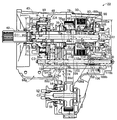
図2から図4は、トランスファ22の概略構成を説明する図であって、図2および図4はトランスファ22の断面図であり、図3はトランスファ22の骨子図である。図2から図4において、トランスファ22は、非回転部材としてのトランスファケース40を備えている。トランスファ22は、トランスファケース40により回転可能に支持された入力軸42および、第1の左右の駆動輪としての後輪16へ動力を出力する後輪側出力軸(出力軸)44と、第2の左右の駆動輪としての前輪14へ動力を出力する、すなわち後輪側出力軸44とは動力の出力先を別にするスプロケット状のドライブギヤ(出力部材)46と、入力軸42の回転を変速して後輪側出力軸44へ伝達する副変速機としてのハイロー切替機構48と、後輪側出力軸44からドライブギヤ46へ伝達する伝達トルクを調整するすなわち後輪側出力軸44の動力の一部を調整してドライブギヤ46に伝達する多板の摩擦クラッチ(多板クラッチ)としての前輪駆動用クラッチ(クラッチ)50とを、共通の第1軸線(軸心)C1回りに備えている。入力軸42および後輪側出力軸44は、相互に同心でそれぞれ回転可能に一対の第1支持ベアリング71および第2支持ベアリング(出力軸支持ベアリング)73を介してトランスファケース40に支持されており、ドライブギヤ46は、後輪側出力軸44に相対回転可能に同心に第3支持ベアリング75を介して支持されている。すなわち、入力軸42、後輪側出力軸44、ドライブギヤ46は、それぞれ第1軸線C1回りに回転可能にトランスファケース40に支持されている。つまり、入力軸42、後輪側出力軸44、ドライブギヤ46は第1軸線C1を共有している。なお、後輪側出力軸44では、入力軸42のリヤ側の端部と後輪側出力軸44のフロント側の端部との間に配設されたベアリング77によって後輪側出力軸44のフロント側の端部が回転可能に支持され、第2支持ベアリング73によって後輪側出力軸44のリヤ側の端部すなわち後輪側出力軸44の両端部のうち後述するドラムカム100側の端部が回転可能に支持されている。   2 to 4 are diagrams for explaining the schematic configuration of the transfer 22, in which FIGS. 2 and 4 are sectional views of the transfer 22, and FIG. 3 is a skeleton diagram of the transfer 22. 2 to 4, the transfer 22 includes a transfer case 40 as a non-rotating member. The transfer 22 includes an input shaft 42 rotatably supported by a transfer case 40, a rear wheel side output shaft (output shaft) 44 that outputs power to the rear wheels 16 as first left and right drive wheels, and a second Power is output to the front wheels 14 as the left and right drive wheels, that is, the sprocket-like drive gear (output member) 46 that separates the power output destination from the rear wheel side output shaft 44 and the rotation of the input shaft 42 are changed. Thus, a high / low switching mechanism 48 serving as an auxiliary transmission that transmits to the rear wheel side output shaft 44 and a transmission torque that is transmitted from the rear wheel side output shaft 44 to the drive gear 46 are adjusted, that is, the power of the rear wheel side output shaft 44 is adjusted. A front-wheel drive clutch (clutch) 50 as a multi-plate friction clutch (multi-plate clutch) that is partially adjusted and transmitted to the drive gear 46 is provided around a common first axis (axis) C1. That. The input shaft 42 and the rear wheel side output shaft 44 are supported by the transfer case 40 via a pair of first support bearings 71 and second support bearings (output shaft support bearings) 73 so as to be concentric with each other and rotatable. The drive gear 46 is supported by a rear wheel side output shaft 44 via a third support bearing 75 concentrically so as to be relatively rotatable. That is, the input shaft 42, the rear wheel side output shaft 44, and the drive gear 46 are supported by the transfer case 40 so as to be rotatable around the first axis C1. That is, the input shaft 42, the rear wheel side output shaft 44, and the drive gear 46 share the first axis C1. In the rear wheel side output shaft 44, a bearing 77 disposed between the rear side end portion of the input shaft 42 and the front side end portion of the rear wheel side output shaft 44 is used. The front side end portion is rotatably supported, and the rear end portion of the rear wheel side output shaft 44, that is, the end portion of the rear wheel side output shaft 44 on the drum cam 100 side, which will be described later, is supported by the second support bearing 73. Is rotatably supported.

図2から図4に示すように、トランスファ22は、トランスファケース40内において、前輪側出力軸52と、前輪側出力軸52に一体的に設けられたスプロケット状のドリブンギヤ54とを第1軸線C1に平行な共通の第2軸線C2回りに備えている。更に、トランスファ22は、ドライブギヤ46とドリブンギヤ54との間に巻き掛けられた前輪駆動用チェーン56と、後輪側出力軸44およびドライブギヤ46を一体的に連結するドグクラッチとして4WDロック機構58と、を備えている。   As shown in FIGS. 2 to 4, in the transfer case 40, the transfer 22 includes a front wheel side output shaft 52 and a sprocket-like driven gear 54 provided integrally with the front wheel side output shaft 52 in a first axis C <b> 1. Around a common second axis C2. Further, the transfer 22 includes a front wheel drive chain 56 wound between the drive gear 46 and the driven gear 54, and a 4WD lock mechanism 58 as a dog clutch that integrally connects the rear wheel side output shaft 44 and the drive gear 46. It is equipped with.

入力軸42は、変速機20の出力軸(不図示)に継手を介して連結されており、エンジン12から変速機20を介して入力された駆動力(トルク)によって回転駆動させられる。後輪側出力軸44は、リヤプロペラシャフト26に連結された主駆動軸である。ドライブギヤ46は、後輪側出力軸44の第1軸線C1まわりに相対回転可能に設けられている。前輪側出力軸52は、フロントプロペラシャフト24に図示しない継手を介して連結された副駆動軸である。   The input shaft 42 is connected to an output shaft (not shown) of the transmission 20 via a joint, and is rotationally driven by a driving force (torque) input from the engine 12 via the transmission 20. The rear wheel side output shaft 44 is a main drive shaft connected to the rear propeller shaft 26. The drive gear 46 is provided so as to be relatively rotatable around the first axis C <b> 1 of the rear wheel side output shaft 44. The front wheel side output shaft 52 is a sub drive shaft connected to the front propeller shaft 24 via a joint (not shown).

このように構成されたトランスファ22は、ドライブギヤ46へ伝達する伝達トルクを前輪駆動用クラッチ50により調整して、変速機20から伝達された動力を後輪16のみへ伝達したり、或いは前輪14にも分配する。また、トランスファ22は、4WDロック機構58によりリヤプロペラシャフト26とフロントプロペラシャフト24との間の回転差を発生させない4WDロック状態とそれらの間の回転差を許容する4WD非ロック状態とのいずれかに切り替える。また、トランスファ22は、高速側ギヤ段(高速側変速段)H及び低速側ギヤ段(低速側変速段)Lの何れかを成立させて、変速機20からの回転を変速して後段へ伝達する。つまり、トランスファ22は、入力軸42の回転をハイロー切替機構48を介して後輪側出力軸44へ伝達すると共に、前輪駆動用クラッチ50を介した伝達トルクが零とされ且つ4WDロック機構58が解放された状態では、後輪側出力軸44から前輪側出力軸52への動力伝達は行われない一方で、前輪駆動用クラッチ50を介してトルクが伝達されるか或いは4WDロック機構58が係合された状態では、後輪側出力軸44からドライブギヤ46、前輪駆動用チェーン56、及びドリブンギヤ54を介して前輪側出力軸52への動力伝達が行われる。   The transfer 22 configured as described above adjusts the transmission torque transmitted to the drive gear 46 by the front wheel drive clutch 50 and transmits the power transmitted from the transmission 20 only to the rear wheel 16 or the front wheel 14. Also distribute to. Further, the transfer 22 is either a 4WD locked state in which a rotational difference between the rear propeller shaft 26 and the front propeller shaft 24 is not generated by the 4WD lock mechanism 58 or a 4WD unlocked state in which a rotational difference between them is allowed. Switch to. Further, the transfer 22 establishes either the high speed side gear stage (high speed side gear stage) H or the low speed side gear stage (low speed side gear stage) L to shift the rotation from the transmission 20 and transmit it to the subsequent stage. To do. In other words, the transfer 22 transmits the rotation of the input shaft 42 to the rear wheel side output shaft 44 via the high / low switching mechanism 48, the transmission torque via the front wheel drive clutch 50 is made zero, and the 4WD lock mechanism 58 is In the released state, power is not transmitted from the rear wheel output shaft 44 to the front wheel output shaft 52, but torque is transmitted through the front wheel drive clutch 50 or the 4WD lock mechanism 58 is engaged. In the combined state, power is transmitted from the rear wheel side output shaft 44 to the front wheel side output shaft 52 via the drive gear 46, the front wheel drive chain 56, and the driven gear 54.

具体的には、ハイロー切替機構48は、シングルピニオン型の遊星歯車装置60と、ハイロースリーブ62とを備えている。遊星歯車装置60は、入力軸42に対して第1軸線C1回りの回転不能に連結されたサンギヤSと、サンギヤSに対して略同心に配置され、トランスファケース40に第1軸線C1回りの回転不能に連結されたリングギヤRと、これらサンギヤS及びリングギヤRに噛み合う複数のピニオンギヤPを自転可能且つサンギヤS回りの公転可能に支持するキャリヤCAとを有している。このため、サンギヤSの回転速度は入力軸42に対して等速であり、キャリヤCAの回転速度は入力軸42に対して減速される。また、サンギヤSの内周面にはハイ側ギヤ歯64が固設されており、キャリヤCAにはハイ側ギヤ歯64と同径のロー側ギヤ歯66が固設されている。ハイ側ギヤ歯64は、入力軸42と等速の回転を出力する、高速側ギヤ段Hの成立に関与するスプライン歯である。ロー側ギヤ歯66は、ハイ側ギヤ歯64よりも低速側の回転を出力する、低速側ギヤ段Lの成立に関与するスプライン歯である。ハイロースリーブ62は、後輪側出力軸44に第1軸線C1と平行な方向の相対移動可能にスプライン嵌合されており、フォーク連結部62aと、フォーク連結部62aと隣接して一体的に設けられた、後輪側出力軸44の第1軸線C1と平行な方向への移動によってハイ側ギヤ歯64とロー側ギヤ歯66とにそれぞれ噛み合う外周歯62bとを有している。ハイ側ギヤ歯64と外周歯62bとが噛み合うことで、入力軸42の回転と等速の回転が後輪側出力軸44へ伝達され、ロー側ギヤ歯66と外周歯62bとが噛み合うことで、入力軸42の回転に対して減速された回転が後輪側出力軸44へ伝達される。ハイ側ギヤ歯64とハイロースリーブ62とは、高速側ギヤ段Hを形成する高速側ギヤ段用クラッチとして機能し、ロー側ギヤ歯66とハイロースリーブ62とは、低速側ギヤ段Lを形成する低速側ギヤ段用クラッチとして機能する。   Specifically, the high / low switching mechanism 48 includes a single pinion type planetary gear device 60 and a high / low sleeve 62. The planetary gear device 60 is disposed so as to be substantially concentric with the sun gear S and the sun gear S that is non-rotatably connected around the first axis C1 with respect to the input shaft 42, and rotates around the first axis C1 in the transfer case 40. A ring gear R that is impossiblely connected, and a carrier CA that supports the sun gear S and a plurality of pinion gears P meshing with the ring gear R so as to rotate and revolve around the sun gear S are provided. For this reason, the rotational speed of the sun gear S is constant with respect to the input shaft 42, and the rotational speed of the carrier CA is decelerated with respect to the input shaft 42. Further, high side gear teeth 64 are fixed to the inner peripheral surface of the sun gear S, and low side gear teeth 66 having the same diameter as the high side gear teeth 64 are fixed to the carrier CA. The high-side gear teeth 64 are spline teeth that are involved in the establishment of the high-speed side gear stage H that outputs a rotation at the same speed as the input shaft 42. The low-side gear teeth 66 are spline teeth that are involved in the establishment of the low-speed side gear stage L that outputs rotation at a lower speed side than the high-side gear teeth 64. The high / low sleeve 62 is spline-fitted to the rear wheel side output shaft 44 so as to be relatively movable in a direction parallel to the first axis C1, and is integrally provided adjacent to the fork connecting portion 62a and the fork connecting portion 62a. The rear wheel side output shaft 44 has outer teeth 62b that mesh with the high side gear teeth 64 and the low side gear teeth 66, respectively, by moving in the direction parallel to the first axis C1. The high side gear teeth 64 and the outer peripheral teeth 62b mesh with each other, whereby the rotation of the input shaft 42 and the rotation at the same speed are transmitted to the rear wheel side output shaft 44, and the low side gear teeth 66 and the outer peripheral teeth 62b mesh with each other. The rotation decelerated with respect to the rotation of the input shaft 42 is transmitted to the rear wheel output shaft 44. The high side gear teeth 64 and the high / low sleeve 62 function as a high speed side gear stage clutch that forms the high speed side gear stage H, and the low side gear teeth 66 and the high / low sleeve 62 form the low speed side gear stage L. Functions as a low speed gear clutch.

4WDロック機構58は、ドライブギヤ46の内周面に固設されたロック歯68と、後輪側出力軸44に対して第1軸線C1方向の移動可能且つ相対回転不能にスプライン嵌合されすなわち後輪側出力軸44に第1軸線C1方向に移動可能且つ第1軸線C1まわりに相対回転不能に支持されて、第1軸線C1方向の移動でドライブギヤ46に形成されたロック歯68に噛み合う噛合歯70aが固設されたロックスリーブ70とを備えている。トランスファ22では、ロックスリーブ70の噛合歯70aとロック歯68とが噛み合ったすなわちロックスリーブ70の噛合歯70aがドライブギヤ46のロック歯68に嵌合した4WDロック機構58の係合状態では、後輪側出力軸44とドライブギヤ46とが直結化され後輪側出力軸44とドライブギヤ46とが一体的に回転させられて、4WDロック状態が形成される。   The 4WD lock mechanism 58 is spline-fitted to the lock teeth 68 fixed to the inner peripheral surface of the drive gear 46 and the rear wheel side output shaft 44 so as to be movable in the first axis C1 direction and not relatively rotatable. The rear wheel side output shaft 44 is supported so as to be movable in the direction of the first axis C1 and not relatively rotatable around the first axis C1, and meshes with the lock teeth 68 formed in the drive gear 46 by movement in the direction of the first axis C1. And a locking sleeve 70 to which meshing teeth 70a are fixed. In the transfer 22, in the engaged state of the 4WD lock mechanism 58 in which the meshing tooth 70 a of the lock sleeve 70 meshes with the lock tooth 68, that is, the meshing tooth 70 a of the lock sleeve 70 is engaged with the lock tooth 68 of the drive gear 46. The wheel side output shaft 44 and the drive gear 46 are directly connected, and the rear wheel side output shaft 44 and the drive gear 46 are integrally rotated to form a 4WD lock state.

ハイロースリーブ62は、入力軸42に設けられた第1支持ベアリング71に対して(より具体的には遊星歯車装置60に対して)ドライブギヤ46側の空間に設けられている。ロックスリーブ70は、ハイロー切替機構48とドライブギヤ46との間の空間に、ハイロースリーブ62と隣接して別体で設けられている。ハイ側ギヤ歯64は、第1軸線C1に平行な方向に見てロー側ギヤ歯66よりもロックスリーブ70から離れた位置に設けられている。ハイロースリーブ62の外周歯62bは、ハイロースリーブ62がロックスリーブ70から離間する側(図2、3において左側)にてハイ側ギヤ歯64に噛み合い、ハイロースリーブ62がロックスリーブ70に接近する側(図2、3において右側)にてロー側ギヤ歯66に噛み合う。ロックスリーブ70の噛合歯70aは、ロックスリーブ70がドライブギヤ46に接近する側(図2、3において右側)にてロック歯68に噛み合う。   The high / low sleeve 62 is provided in a space on the drive gear 46 side with respect to the first support bearing 71 provided on the input shaft 42 (more specifically, with respect to the planetary gear device 60). The lock sleeve 70 is provided as a separate member adjacent to the high / low sleeve 62 in the space between the high / low switching mechanism 48 and the drive gear 46. The high side gear teeth 64 are provided at a position farther from the lock sleeve 70 than the low side gear teeth 66 when viewed in a direction parallel to the first axis C1. The outer peripheral teeth 62b of the high / low sleeve 62 mesh with the high gear teeth 64 on the side where the high / low sleeve 62 is separated from the lock sleeve 70 (left side in FIGS. 2 and 3), and the side where the high / low sleeve 62 approaches the lock sleeve 70 ( In FIG. 2 and FIG. The meshing teeth 70 a of the lock sleeve 70 mesh with the lock teeth 68 on the side where the lock sleeve 70 approaches the drive gear 46 (right side in FIGS. 2 and 3).

前輪駆動用クラッチ50は、後輪側出力軸44に相対回転不能に連結されたクラッチハブ76と、ドライブギヤ46に相対回転不能に連結されたクラッチドラム78と、クラッチハブ76とクラッチドラム78との間に介挿されこれらを選択的に断接する摩擦係合要素80と、摩擦係合要素80を押圧するピストン82と、を備える多板の摩擦クラッチである。前輪駆動用クラッチ50は、後輪側出力軸44の第1軸線C1方向で、ドライブギヤ46に対してハイロー切替機構48とは反対側に後輪側出力軸44の第1軸線C1回りに配置されて、ドライブギヤ46側に移動するピストン82によって摩擦係合要素80が押し付けられる。前輪駆動用クラッチ50は、ピストン82がドライブギヤ46から第1軸線C1に平行な方向に離れる側である非押圧側(図2、3において右側)に移動させられて摩擦係合要素80に当接しない状態では、解放状態となる。一方で、前輪駆動用クラッチ50は、ピストン82がドライブギヤ46に第1軸線C1に平行な方向に近づく側である押圧側(図2、3において左側)に移動させられて摩擦係合要素80に当接する状態では、ピストン82の移動量によって伝達トルク(トルク容量)が調整され、解放状態、スリップ状態、又は係合状態となる。   The front-wheel drive clutch 50 includes a clutch hub 76 that is non-rotatably connected to the rear-wheel output shaft 44, a clutch drum 78 that is non-rotatably connected to the drive gear 46, a clutch hub 76, and a clutch drum 78. It is a multi-plate friction clutch provided with a frictional engagement element 80 inserted between them and selectively connecting / disconnecting them, and a piston 82 for pressing the frictional engagement element 80. The front-wheel drive clutch 50 is disposed around the first axis C1 of the rear-wheel output shaft 44 on the opposite side of the drive gear 46 from the high / low switching mechanism 48 in the first axis C1 direction of the rear-wheel-side output shaft 44. Then, the friction engagement element 80 is pressed by the piston 82 that moves to the drive gear 46 side. The front-wheel drive clutch 50 is moved to the non-pressing side (the right side in FIGS. 2 and 3), which is the side where the piston 82 is separated from the drive gear 46 in the direction parallel to the first axis C 1. When not in contact, it is in a released state. On the other hand, the front-wheel drive clutch 50 is moved to the pressing side (the left side in FIGS. 2 and 3), which is the side where the piston 82 approaches the drive gear 46 in the direction parallel to the first axis C <b> 1. In the state of contacting, the transmission torque (torque capacity) is adjusted by the amount of movement of the piston 82, and the disengaged state, the slip state, or the engaged state is obtained.

トランスファ22は、前輪駆動用クラッチ50の解放状態且つロックスリーブ70の噛合歯70aとロック歯68とが噛み合っていない4WDロック機構58の解放状態では、後輪側出力軸44とドライブギヤ46との間の動力伝達経路が遮断されて、変速機20から伝達された動力を後輪16のみへ伝達する。トランスファ22は、前輪駆動用クラッチ50のスリップ状態または係合状態では、変速機20から伝達された動力を前輪14及び後輪16のそれぞれに分配する。トランスファ22は、前輪駆動用クラッチ50のスリップ状態では、後輪側出力軸44とドライブギヤ46との間の回転差動が許容されて、差動状態(4WD非ロック状態)が形成される。トランスファ22は、前輪駆動用クラッチ50の係合状態では、後輪側出力軸44とドライブギヤ46とが一体的に回転させられて、4WDロック状態が形成される。前輪駆動用クラッチ50は、伝達トルクが制御されることで、前輪14と後輪16とのトルク配分を例えば0:100〜50:50の間で連続的に変更することができる。   In the released state of the front wheel drive clutch 50 and the released state of the 4WD lock mechanism 58 in which the engagement teeth 70a of the lock sleeve 70 and the lock teeth 68 are not engaged with each other, the transfer 22 The power transmission path therebetween is cut off, and the power transmitted from the transmission 20 is transmitted only to the rear wheels 16. The transfer 22 distributes the power transmitted from the transmission 20 to each of the front wheels 14 and the rear wheels 16 when the front wheel drive clutch 50 is in a slip state or an engaged state. In the slip state of the front wheel drive clutch 50, the transfer 22 is allowed to rotate differentially between the rear wheel side output shaft 44 and the drive gear 46, thereby forming a differential state (4WD non-lock state). In the transfer 22 in the engaged state of the front wheel drive clutch 50, the rear wheel side output shaft 44 and the drive gear 46 are integrally rotated to form a 4WD lock state. The front-wheel drive clutch 50 can continuously change the torque distribution between the front wheels 14 and the rear wheels 16, for example, between 0: 100 and 50:50 by controlling the transmission torque.

トランスファ22は、ハイロー切替機構48、前輪駆動用クラッチ50、及び4WDロック機構58を作動させる装置として、電動モータ(電動機)84(図3参照)と、電動モータ84の回転運動力をハイロー切替機構48、前輪駆動用クラッチ50、及び4WDロック機構58へそれぞれ伝達する伝達機構88とを、更に備えている。なお、上記伝達機構88では、電動モータ84の回転運動を直線運動に変換するネジ機構86のナット部材92の直線運動力を前輪駆動用クラッチ50へ伝達し、ナット部材92の回転運動力を後述するドラムカム100等を介してハイロー切替機構48、4WDロック機構58へ伝達している。   The transfer 22 is a device for operating the high / low switching mechanism 48, the front wheel driving clutch 50, and the 4WD lock mechanism 58, and an electric motor (electric motor) 84 (see FIG. 3) and the rotational motion force of the electric motor 84 are switched to a high / low switching mechanism. 48, a front wheel drive clutch 50, and a transmission mechanism 88 for transmitting to the 4WD lock mechanism 58, respectively. In the transmission mechanism 88, the linear motion force of the nut member 92 of the screw mechanism 86 that converts the rotational motion of the electric motor 84 to linear motion is transmitted to the front wheel drive clutch 50, and the rotational motion force of the nut member 92 is described later. Is transmitted to the high / low switching mechanism 48 and the 4WD lock mechanism 58 via the drum cam 100 or the like.

ネジ機構86は、前輪駆動用クラッチ50に対してドライブギヤ46とは反対側において後輪側出力軸44と同じ第1軸線C1回りに配置されており、トランスファ22に備えられたウォームギヤ90を介して電動モータ84に間接的に連結された回転部材としてのナット部材(一方のネジ部材)92と、ナット部材92に螺合するネジ軸部材(他方のネジ部材)94と、ネジ軸部材94を後輪側出力軸44の第1軸線C1方向に移動不能且つ第1軸線C1回りの回動不能に後輪側出力軸44に配設するためにネジ軸部材94のリヤ側の端部と非回転部材であるトランスファケース40との間を連結する連結部材95とを備えている。なお、ナット部材92は、複数のボール96を介してネジ軸部材94と螺合しており、ネジ機構86は、ナット部材92とネジ軸部材94とが複数のボール96を介して作動するボールネジである。このように構成されたネジ機構86では、後輪側出力軸44に支持され、互いに螺合するネジ軸部材94およびナット部材92のいずれか一方のネジ部材であるナット部材92が電動モータ84により回転駆動させられることによって、ナット部材92が、後輪側出力軸44の第1軸線C1方向に移動する。なお、後輪側出力軸44に支持されたナット部材92およびネジ軸部材94において、ナット部材92がネジ軸部材94に螺合することによって、ナット部材92は後輪側出力軸44に後輪側出力軸44の第1軸線C1まわりに回転可能に支持され、連結部材95によって、ネジ軸部材94は後輪側出力軸44の第1軸線C1方向に移動不能かつ後輪側出力軸44の第1軸線C1まわりに回転不能に後輪側出力軸44に支持されている。また、本実施例において、図2および図5に示すようにナット部材92が電動モータ84によって第1軸線C1まわり矢印F1方向に回動させられると、ナット部材92がネジ軸部材94とのネジの作用によって第1軸線方向C1において前輪駆動用クラッチ50から離間する方向すなわち矢印F2方向に移動するようになっている。   The screw mechanism 86 is disposed around the same first axis C <b> 1 as the rear wheel output shaft 44 on the opposite side of the drive gear 46 with respect to the front wheel drive clutch 50, and is connected via a worm gear 90 provided in the transfer 22. A nut member (one screw member) 92 as a rotating member indirectly connected to the electric motor 84, a screw shaft member (the other screw member) 94 screwed into the nut member 92, and a screw shaft member 94. In order to dispose the rear wheel side output shaft 44 on the rear wheel side output shaft 44 so that the rear wheel side output shaft 44 cannot move in the direction of the first axis C1 and cannot rotate about the first axis C1, the rear end of the screw shaft member 94 is not And a connecting member 95 that connects the transfer case 40 that is a rotating member. The nut member 92 is screwed with the screw shaft member 94 via a plurality of balls 96, and the screw mechanism 86 is a ball screw in which the nut member 92 and the screw shaft member 94 are operated via the plurality of balls 96. It is. In the screw mechanism 86 configured in this way, the nut member 92, which is one of the screw shaft member 94 and the nut member 92 that are supported by the rear wheel side output shaft 44 and screwed together, is driven by the electric motor 84. By being driven to rotate, the nut member 92 moves in the direction of the first axis C <b> 1 of the rear wheel side output shaft 44. In the nut member 92 and the screw shaft member 94 supported by the rear wheel side output shaft 44, the nut member 92 is screwed into the screw shaft member 94, so that the nut member 92 is connected to the rear wheel side output shaft 44. The screw shaft member 94 cannot be moved in the direction of the first axis C1 of the rear wheel side output shaft 44 by the connecting member 95 and can be rotated around the first axis C1 of the side output shaft 44. The rear wheel side output shaft 44 is supported so as not to rotate about the first axis C1. In this embodiment, as shown in FIGS. 2 and 5, when the nut member 92 is rotated around the first axis C <b> 1 in the direction of the arrow F <b> 1 by the electric motor 84, the nut member 92 is screwed with the screw shaft member 94. As a result, the first wheel C1 moves in the direction away from the front wheel drive clutch 50 in the first axial direction C1, that is, in the direction of the arrow F2.

ウォームギヤ90は、電動モータ84のモータシャフトと一体的に形成されたウォーム98と、ナット部材92のリヤ側の端部に形成された鍔部92aに固設されたドラムカム100に形成されたウォームホイール100aとを備えた歯車対である。例えばブラシレスモータである電動モータ84の回転は、ウォームギヤ90を介してナット部材92へ減速されて伝達される。ネジ機構86は、ナット部材92に伝達された電動モータ84の回転を、ナット部材92の直線運動に変換する。また、電動モータ84が回転駆動することによって、ナット部材92に連結すなわち固設されたドラムカム100に形成されたウォームホイール100aが後輪側出力軸44の第1軸線C1方向に移動するが、ウォームホイール100aが移動しても、ウォームホイール100aとトランスファケース40に固定された電動モータ84のモータシャフトに形成されたウォーム98とが常時噛み合うように、ウォームホイール100aの第1軸線C1方向の幅寸法が上記モータシャフトに形成されたウォーム98の第1軸線C1方向の幅寸法より大きくなっており、ウォームホイール100aの外周歯が平歯に形成されている。   The worm gear 90 includes a worm 98 formed integrally with the motor shaft of the electric motor 84 and a worm wheel formed on a drum cam 100 fixed to a flange 92 a formed on the rear end of the nut member 92. 100a is a pair of gears. For example, the rotation of the electric motor 84, which is a brushless motor, is transmitted to the nut member 92 at a reduced speed via the worm gear 90. The screw mechanism 86 converts the rotation of the electric motor 84 transmitted to the nut member 92 into a linear motion of the nut member 92. Further, when the electric motor 84 is driven to rotate, the worm wheel 100a formed on the drum cam 100 connected to or fixed to the nut member 92 moves in the direction of the first axis C1 of the rear wheel side output shaft 44. Even if the wheel 100a moves, the width dimension of the worm wheel 100a in the first axis C1 direction so that the worm 98 formed on the motor shaft of the electric motor 84 fixed to the transfer case 40 is always engaged. Is larger than the width dimension of the worm 98 formed on the motor shaft in the first axis C1 direction, and the outer peripheral teeth of the worm wheel 100a are formed as spur teeth.

伝達機構88には、電動モータ84の回転運動に連動して、ハイロースリーブ62とロックスリーブ70とが、ハイロー切替機構48において高速側ギヤ段Hが成立され且つ後輪側出力軸44とドライブギヤ46とが直結化するH4L位置と、ハイロー切替機構48において低速側ギヤ段Lが成立され且つ後輪側出力軸44とドライブギヤ46とが直結化するL4L位置と、ハイロー切替機構48において高速側ギヤ段Hが成立され且つ後輪側出力軸44とドライブギヤ46とが直結化されないハイギヤ(H4またはH2)位置とに選択的に切り替えられる切替機構88aが、備えられている。なお、上記H4L位置は、ハイロースリーブ62の外周歯62bがハイ側ギヤ歯64に噛み合い且つロックスリーブ70の噛合歯70aがロック歯68に噛み合う位置である。また、上記L4L位置は、ハイロースリーブ62の外周歯62bがロー側ギヤ歯66に噛み合い且つロックスリーブ70の噛合歯70aがロック歯68に噛み合う位置である。また、上記ハイギヤ(H4またはH2)位置は、ハイロースリーブ62の外周歯62bがハイ側ギヤ歯64に噛み合い且つロックスリーブ70の噛合歯70aがロック歯68に噛み合わない位置である。また、伝達機構88には、ネジ機構86におけるナット部材92の直線運動を前輪駆動用クラッチ50に伝達する第1伝達機構(伝達機構)88bが備えられている。   In the transmission mechanism 88, the high / low sleeve 62 and the lock sleeve 70 are interlocked with the rotational movement of the electric motor 84, the high speed side gear stage H is established in the high / low switching mechanism 48, and the rear wheel side output shaft 44 and the drive gear. 46, the L4L position where the low-speed gear stage L is established in the high / low switching mechanism 48 and the rear wheel side output shaft 44 and the drive gear 46 are directly connected, and the high / low switching mechanism 48 is the high speed side. A switching mechanism 88a is provided that is selectively switched to a high gear (H4 or H2) position where the gear stage H is established and the rear wheel output shaft 44 and the drive gear 46 are not directly connected. The H4L position is a position where the outer peripheral teeth 62b of the high / low sleeve 62 mesh with the high side gear teeth 64 and the meshing teeth 70a of the lock sleeve 70 mesh with the lock teeth 68. The L4L position is a position where the outer peripheral teeth 62 b of the high / low sleeve 62 mesh with the low gear gear 66 and the meshing tooth 70 a of the lock sleeve 70 meshes with the lock tooth 68. The high gear (H4 or H2) position is a position where the outer peripheral teeth 62b of the high / low sleeve 62 mesh with the high side gear teeth 64 and the meshing teeth 70a of the lock sleeve 70 do not mesh with the lock teeth 68. Further, the transmission mechanism 88 includes a first transmission mechanism (transmission mechanism) 88 b that transmits the linear motion of the nut member 92 in the screw mechanism 86 to the front wheel drive clutch 50.

切替機構88aには、ドラムカム100に形成されたカム溝100cに係合された後述するカム係合部材103が連結されたフォークシャフト(第2軸)102の第3軸線(軸心)C3方向の移動をハイロー切替機構48に伝達する第2伝達機構88cと、フォークシャフト102の第3軸線C3方向の移動を4WDロック機構58に伝達する第3伝達機構88dと、が備えられている。なお、フォークシャフト102は、カム係合部材103に連結され、トランスファケース40内において後輪側出力軸44と平行に配置され且つ第3軸線C3方向に移動可能に支持されている。   The switching mechanism 88a has a fork shaft (second shaft) 102 in the direction of the third axis (axial center) C3 connected to a cam engaging member 103 (described later) engaged with a cam groove 100c formed in the drum cam 100. A second transmission mechanism 88c that transmits the movement to the high / low switching mechanism 48 and a third transmission mechanism 88d that transmits the movement of the fork shaft 102 in the direction of the third axis C3 to the 4WD lock mechanism 58 are provided. The fork shaft 102 is connected to the cam engagement member 103, is disposed in parallel with the rear wheel output shaft 44 in the transfer case 40, and is supported so as to be movable in the direction of the third axis C3.

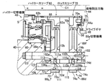
図2および図5に示すように、ドラムカム100は、電動モータ84のモータシャフトに形成されたウォーム98と噛み合う円環状のウォームホイール100aと、ウォームホイール100aのフォークシャフト102側の端部においてウォームホイール100aからリヤプロペラシャフト26に接近する方向に突き出された突部100bと、その突部100bの外周に形成されたカム溝100cとが備えられている。なお、上記突部100bは、ウォームホイール100aの円周方向の一部がリヤプロペラシャフト26に接近する方向に突き出された例えば円筒形状の一部分を示す形状である。後輪側出力軸44の両端部のうちドラムカム100側の端部を回転可能に支持する第2支持ベアリング73は、ドラムカム100の後輪側出力軸44の第1軸線C1方向の長さ範囲内にドラムカム100の内側に配置されている。また、ドラムカム100の後輪側出力軸44の径方向の寸法R1は、ハイロー切替機構48の後輪側出力軸44の径方向の寸法R2および前輪駆動用クラッチ50の後輪側出力軸44の径方向の寸法R3以下になるように、ドラムカム100が形成されている。上記寸法R2は、ハイロー切替機構48のリングギヤRまたはキャリヤCAの外径寸法である。上記寸法R3は、前輪駆動用クラッチ50のクラッチドラム78の外径寸法である。   2 and 5, the drum cam 100 includes an annular worm wheel 100a that meshes with a worm 98 formed on the motor shaft of the electric motor 84, and a worm wheel at the end of the worm wheel 100a on the fork shaft 102 side. A protrusion 100b protruding from 100a in a direction approaching the rear propeller shaft 26 and a cam groove 100c formed on the outer periphery of the protrusion 100b are provided. The protrusion 100b has a shape indicating a part of, for example, a cylindrical shape in which a part of the worm wheel 100a in the circumferential direction protrudes in a direction approaching the rear propeller shaft 26. The second support bearing 73 that rotatably supports the end portion of the rear wheel side output shaft 44 on the drum cam 100 side is within the length range of the rear wheel side output shaft 44 of the drum cam 100 in the first axis C1 direction. Is disposed inside the drum cam 100. The radial dimension R1 of the rear wheel side output shaft 44 of the drum cam 100 is equal to the radial dimension R2 of the rear wheel side output shaft 44 of the high / low switching mechanism 48 and the rear wheel side output shaft 44 of the front wheel drive clutch 50. The drum cam 100 is formed so as to be equal to or less than the radial dimension R3. The dimension R2 is an outer diameter dimension of the ring gear R of the high / low switching mechanism 48 or the carrier CA. The dimension R3 is an outer diameter dimension of the clutch drum 78 of the front-wheel drive clutch 50.

図6に示すように、ドラムカム100に形成されたカム溝100cは、後輪側出力軸44の第1軸線C1に対して傾斜する方向に伸びた第1傾斜カム溝部100dと、第1傾斜カム溝部100dのネジ機構86側の端部に形成され、第1軸線C1に対して垂直方向に伸びた第1カム溝部100eと、第1傾斜カム溝部100dに対してネジ機構86側とは反対側に配設され、後輪側出力軸44の第1軸線C1に対して傾斜する方向に伸びた第2傾斜カム溝部100fと、第2傾斜カム溝部100fのネジ機構86側の端部と第1傾斜カム溝部100dのネジ機構86側とは反対側の端部とを連結し、第1軸線C1に対して垂直方向に伸びた第2カム溝部100gと、第2傾斜カム溝部100fのネジ機構86側とは反対側の端部に形成され、第1軸線C1に対して垂直方向に伸びた第3カム溝部100hとを有している。このように構成されたドラムカム100によれば、例えば図6の(a)に示すように、ドラムカム100のカム溝100cの第1カム溝部100e内にカム係合部材103が配置された状態から、電動モータ84によってナット部材92が第1軸線C1回り矢印F1方向に回動されると共にドラムカム100が第1軸線C1回り矢印F1方向に回動させられると、ドラムカム100の第1傾斜カム溝部100d、第2カム溝部100g、第2傾斜カム溝部100fに沿ってカム係合部材103が、ナット部材92の矢印F2方向の移動量、すなわちナット部材92がネジ軸部材94とのネジの作用よって矢印F2方向に移動する移動量より大きい移動量Dで矢印F2方向すなわちフォークシャフト102の第3軸線C3方向に移動させられる。また、例えば図6の(c)に示すように、ドラムカム100のカム溝100cの第3カム溝部100h内にカム係合部材103が配置された状態から、電動モータ84によってナット部材92が第1軸線C1回り矢印F1方向とは反対方向に回動されると共にドラムカム100が第1軸線C1回り矢印F1方向とは反対方向に回動させられると、ドラムカム100の第2傾斜カム溝部100f、第2カム溝部100g、第1傾斜カム溝部100dに沿ってカム係合部材103が、ナット部材92の矢印F2方向とは反対方向の移動量、すなわちナット部材92がネジ軸部材94とのネジの作用よって矢印F2方向とは反対方向に移動する移動量より大きい移動量Dで矢印F2方向とは反対方向に移動させられる。すなわち、電動モータ84が回転駆動しナット部材92を介してドラムカム100が後輪側出力軸44の第1軸線C1回りに回動させられると、ドラムカム100に形成されたカム溝100cによってそのカム溝100cに係合されたカム係合部材103が後輪側出力軸44の第1軸線C1と平行にトランスアクスルケース40内に配置されたフォークシャフト102の第3軸線C3方向に移動させられる。なお、図6の(b)および(c)に示されている1点鎖線の円は、図6の(a)のカム係合部材103の位置を示すものである。後輪側出力軸44の第1軸線C1と、前輪側出力軸52の第2軸線C2と、フォークシャフト102の第3軸線C3とはそれぞれ平行である。   As shown in FIG. 6, the cam groove 100c formed in the drum cam 100 includes a first inclined cam groove portion 100d extending in a direction inclined with respect to the first axis C1 of the rear wheel side output shaft 44, and a first inclined cam. A first cam groove portion 100e formed at an end of the groove portion 100d on the screw mechanism 86 side and extending in a direction perpendicular to the first axis C1, and a side opposite to the screw mechanism 86 side with respect to the first inclined cam groove portion 100d A second inclined cam groove portion 100f extending in a direction inclined with respect to the first axis C1 of the rear wheel side output shaft 44, an end portion of the second inclined cam groove portion 100f on the screw mechanism 86 side, and the first inclined cam groove portion 100f. The end portion of the inclined cam groove portion 100d opposite to the screw mechanism 86 side is connected, the second cam groove portion 100g extending in the direction perpendicular to the first axis C1, and the screw mechanism 86 of the second inclined cam groove portion 100f. Formed at the end opposite the side, And a third cam groove 100h extending in a direction perpendicular to the first axis C1. According to the drum cam 100 configured as described above, for example, as shown in FIG. 6A, from the state where the cam engagement member 103 is disposed in the first cam groove portion 100e of the cam groove 100c of the drum cam 100, When the nut member 92 is rotated around the first axis C1 in the direction of the arrow F1 and the drum cam 100 is rotated around the first axis C1 in the direction of the arrow F1 by the electric motor 84, the first inclined cam groove portion 100d of the drum cam 100, The cam engagement member 103 moves along the second cam groove portion 100g and the second inclined cam groove portion 100f in the direction of the arrow F2 of the nut member 92, that is, the arrow F2 by the action of the screw of the nut member 92 with the screw shaft member 94. Is moved in the direction of arrow F2, that is, in the direction of the third axis C3 of the fork shaft 102 by a movement amount D larger than the movement amount moving in the directionFurther, for example, as shown in FIG. 6C, the nut member 92 is first moved by the electric motor 84 from the state where the cam engagement member 103 is disposed in the third cam groove portion 100 h of the cam groove 100 c of the drum cam 100. When the drum cam 100 is rotated in the direction opposite to the arrow F1 direction around the axis C1 and the drum cam 100 is rotated in the direction opposite to the arrow F1 direction around the first axis C1, the second inclined cam groove portion 100f of the drum cam 100, the second The cam engagement member 103 moves along the cam groove portion 100g and the first inclined cam groove portion 100d in the direction opposite to the arrow F2 direction of the nut member 92, that is, the nut member 92 is acted by a screw action with the screw shaft member 94. It is moved in the direction opposite to the arrow F2 direction by a movement amount D that is larger than the movement amount moving in the direction opposite to the arrow F2 direction. That is, when the electric motor 84 is driven to rotate and the drum cam 100 is rotated about the first axis C1 of the rear wheel output shaft 44 via the nut member 92, the cam groove 100c formed in the drum cam 100 causes the cam groove The cam engaging member 103 engaged with 100c is moved in the direction of the third axis C3 of the fork shaft 102 disposed in the transaxle case 40 in parallel with the first axis C1 of the rear wheel side output shaft 44. 6B and 6C indicate the position of the cam engagement member 103 in FIG. 6A. The first axis C1 of the rear wheel side output shaft 44, the second axis C2 of the front wheel side output shaft 52, and the third axis C3 of the fork shaft 102 are parallel to each other.

なお、図6において、図6の(a)は、ハイロースリーブ62およびロックスリーブ70がハイギヤ(H4またはH2)位置である時つまりフォークシャフト102がハイギヤ位置である時におけるカム係合部材103の位置を示す図である。また、図6の(b)は、ハイロースリーブ62およびロックスリーブ70がH4L位置ある時つまりフォークシャフト102がH4L位置である時におけるカム係合部材103の位置を示す図である。また、図6の(c)は、ハイロースリーブ62およびロックスリーブ70がL4L位置である時つまりフォークシャフト102がL4L位置である時におけるカム係合部材103の位置を示す図である。   6A shows the position of the cam engaging member 103 when the high / low sleeve 62 and the lock sleeve 70 are in the high gear (H4 or H2) position, that is, when the fork shaft 102 is in the high gear position. FIG. FIG. 6B shows the position of the cam engagement member 103 when the high / low sleeve 62 and the lock sleeve 70 are at the H4L position, that is, when the fork shaft 102 is at the H4L position. FIG. 6C shows the position of the cam engagement member 103 when the high / low sleeve 62 and the lock sleeve 70 are at the L4L position, that is, when the fork shaft 102 is at the L4L position.

図2から図5に示すように、第1伝達機構88bには、前輪駆動用クラッチ50の摩擦係合要素80を押圧するピストン82と、ピストン82とナット部材92の鍔部92aとの間に介在されたスラストベアリング105と、ピストン82のナット部材92に対する摩擦係合要素80側への相対移動を阻止するストッパ部材107とが備えられている。ピストン82は、スラストベアリング105およびストッパ部材107によって、ナット部材92に対して第1軸線C1方向の相対移動不能且つ第1軸線C1回りの相対回転可能にナット部材92に連結されている。これによって、ネジ機構86におけるナット部材92の直線運動は、第1伝達機構88bを介して前輪駆動用クラッチ50の摩擦係合要素80に伝達される。   As shown in FIGS. 2 to 5, the first transmission mechanism 88 b includes a piston 82 that presses the friction engagement element 80 of the front-wheel drive clutch 50, and a piston 82 and a flange 92 a of the nut member 92. An interposed thrust bearing 105 and a stopper member 107 that prevents relative movement of the piston 82 toward the friction engagement element 80 with respect to the nut member 92 are provided. The piston 82 is connected to the nut member 92 by a thrust bearing 105 and a stopper member 107 so as not to move relative to the nut member 92 in the first axis C1 direction and to rotate relative to the first axis C1. Accordingly, the linear motion of the nut member 92 in the screw mechanism 86 is transmitted to the friction engagement element 80 of the front wheel drive clutch 50 via the first transmission mechanism 88b.

また、図2から図5に示すように、第2伝達機構88cには、フォークシャフト102に設けられ、ハイロースリーブ62のフォーク連結部62aに連結されたハイローシフトフォーク72と、フォークシャフト102の第3軸線C3方向の移動をハイローシフトフォーク72に選択的に伝達させ、ハイローシフトフォーク72を第3軸線C3方向にすなわちハイロースリーブ62を第1軸線C1方向に選択的に移動させる第1移動機構88eと、が備えられている。なお、フォークシャフト102とカム係合部材103との間には、フォークシャフト102にカム係合部材103の第1軸線C1方向すなわち第3軸線C3方向の移動をバネ部材112を介して伝達する待ち機構106が備えられている。   2 to 5, the second transmission mechanism 88c includes a high / low shift fork 72 provided on the fork shaft 102 and connected to the fork connecting portion 62a of the high / low sleeve 62, and the second transmission mechanism 88c. The first moving mechanism 88e that selectively transmits the movement in the three axis C3 direction to the high / low shift fork 72 and selectively moves the high / low shift fork 72 in the third axis C3 direction, that is, the high / low sleeve 62 in the first axis C1 direction. And are provided. In addition, between the fork shaft 102 and the cam engaging member 103, a waiting time for transmitting the movement of the cam engaging member 103 in the first axis C1 direction, that is, the third axis C3 direction to the fork shaft 102 via the spring member 112 is waited. A mechanism 106 is provided.

第1移動機構88eには、図7から図9に示すように、フォークシャフト102と平行にトランスファケース40に固定された円柱形状の固定軸109と、ハイローシフトフォーク72がフォークシャフト102と固定軸109とに沿って第3軸線C3方向に移動可能にハイローシフトフォーク72の基端部72aに円柱形状に貫通された一対の貫通孔72b、72cと、ハイローシフトフォーク72の基端部72aにおいて一対の貫通孔72b、72c間を連通する円柱形状の連通孔72dと、連通孔72dの内部に連通孔72dの第4軸線(軸心)C4方向に移動可能に配置され、一端部111aがフォークシャフト102の外周面に形成された第1凹部(凹部)102aに選択的に係合され、他端部111bが固定軸109の外周面に形成された第1凹部(凹部)109aに選択的に係合される円柱状の第1インターロック部材(インターロック部材)111と、フォークシャフト102のハイローシフトフォーク72に対して4WDロックフォーク74とは反対側に固設され、フォークシャフト102の第3軸線C3方向の移動によりハイローシフトフォーク72を選択的に第3軸線C3方向に移動させる環状の第1ストッパー(ストッパー)113とが備えられている。なお、フォークシャフト102の第3軸心C3は固定軸109の第5軸線C5と平行である。   As shown in FIGS. 7 to 9, the first moving mechanism 88 e includes a columnar fixed shaft 109 fixed to the transfer case 40 in parallel with the fork shaft 102, and a high / low shift fork 72 including the fork shaft 102 and the fixed shaft. 109 and a pair of through-holes 72b and 72c penetrating into the base end portion 72a of the high / low shift fork 72 so as to be movable in the third axis C3 direction, and a base end portion 72a of the high / low shift fork 72 A cylindrical communication hole 72d communicating between the through holes 72b and 72c, and a fourth hole (axial center) C4 direction of the communication hole 72d is disposed inside the communication hole 72d, and one end 111a is disposed on the fork shaft. 102 is selectively engaged with a first recess (recess) 102 a formed on the outer peripheral surface of 102, and the other end 111 b is connected to the outer peripheral surface of the fixed shaft 109. A cylindrical first interlock member (interlock member) 111 selectively engaged with the formed first recess (recess) 109a, and a 4WD lock fork 74 with respect to the high / low shift fork 72 of the fork shaft 102; Is provided with an annular first stopper 113 that selectively moves the high / low shift fork 72 in the direction of the third axis C3 by moving the fork shaft 102 in the direction of the third axis C3. Yes. The third axis C3 of the fork shaft 102 is parallel to the fifth axis C5 of the fixed shaft 109.

第1インターロック部材111は、図7から図10に示すように、第1インターロック部材111のフォークシャフト102側の一端部111aおよび第1インターロック部材111の固定軸109側の他端部111bがそれぞれ球面状に形成されており、それら一端部111aと他端部111bとの間には円柱形状の軸部111cが一体に連結されている。また、フォークシャフト102に形成された第1凹部102aは、第1インターロック部材111のフォークシャフト102側の一端部111aが入り込めるように球面状に凹んでおり、固定軸109に形成された第1凹部109aは、第1インターロック部材111の固定軸109側の他端部111bが入り込めるように球面状に凹んでいる。なお、図7はフォークシャフト102がハイギヤ位置である時の状態を示す図であり、図8はフォークシャフト102がH4L位置である時の状態を示す図であり、図9はフォークシャフト102がL4L位置である時の状態を示す図である。また、図10は、第1インターロック部材111および後述する第2インターロック部材115等を説明する図であり、図10の(a)はフォークシャフト102がハイギヤ位置である時の状態を示す図7の拡大図であり、図10の(b)はフォークシャフト102がH4L位置である時の状態を示す図8の拡大図であり、図10の(c)はフォークシャフト102がL4L位置である時の状態を示す図9の拡大図である。   As shown in FIGS. 7 to 10, the first interlock member 111 includes one end 111 a on the fork shaft 102 side of the first interlock member 111 and the other end 111 b on the fixed shaft 109 side of the first interlock member 111. Are formed in a spherical shape, and a cylindrical shaft portion 111c is integrally connected between the one end portion 111a and the other end portion 111b. The first recess 102 a formed in the fork shaft 102 is recessed in a spherical shape so that the one end 111 a on the fork shaft 102 side of the first interlock member 111 can enter, and the first recess 102 a formed in the fixed shaft 109. The recess 109a is recessed in a spherical shape so that the other end 111b of the first interlock member 111 on the fixed shaft 109 side can enter. 7 is a view showing a state when the fork shaft 102 is in the high gear position, FIG. 8 is a view showing a state when the fork shaft 102 is in the H4L position, and FIG. 9 is a view showing when the fork shaft 102 is in the L4L position. It is a figure which shows a state when it is a position. FIG. 10 is a view for explaining the first interlock member 111 and a second interlock member 115 to be described later. FIG. 10A shows a state when the fork shaft 102 is in the high gear position. FIG. 10B is an enlarged view of FIG. 8 showing a state when the fork shaft 102 is at the H4L position, and FIG. 10C is an enlarged view of the fork shaft 102 at the L4L position. It is an enlarged view of FIG. 9 which shows the state of time.

図10の(a)に示すように、第1インターロック部材111のフォークシャフト102側の一端部111aは、その球面の曲率中心CA1が第1インターロック部材111のフォークシャフト102側の一端部111aと第1インターロック部材111の固定軸109側の他端部111bとの間すなわち円柱状の軸部111cに位置するように形成されている。図10の(a)の1点鎖線の円CR1は、第1インターロック部材111のフォークシャフト102側の一端部111aにおける球面の曲率円である。また、図10の(c)に示すように、第1インターロック部材111のフォークシャフト102側の一端部111aがフォークシャフト102の第1凹部102aに係合した状態において、フォークシャフト102が第3軸線C3方向に移動しようとするとその一端部111aの球面の傾斜面にフォークシャフト102の第1凹部102aの開口縁部の傾斜面が当接するように、その第1凹部102aの第4軸線C4方向の深さが設定されている。また、図10の(b)に示すように、第1インターロック部材111の固定軸109側の他端部111bは、その球面の曲率中心CA2が第1インターロック部材111のフォークシャフト102側の一端部111aと第1インターロック部材111の固定軸109側の他端部111bとの間すなわち円柱状の軸部111cに位置するように形成されている。図10の(b)の1点鎖線の円CR2は、第1インターロック部材111の固定軸109側の他端部111bにおける球面の曲率円である。また、図10の(b)に示すように、第1インターロック部材111の固定軸109側の他端部111bが固定軸109の第1凹部109aに係合した状態において、フォークシャフト102が第3軸線C3方向に移動してハイローシフトフォーク72が第3軸線C3方向に移動しようとするとその他端部111bの球面の傾斜面に固定軸109の第1凹部109aの開口縁部の傾斜面が当接するように、その第1凹部109aの第4軸線C4方向の深さが設定されている。   As shown in FIG. 10A, the one end 111a of the first interlock member 111 on the fork shaft 102 side has a spherical center of curvature CA1 at one end 111a of the first interlock member 111 on the fork shaft 102 side. And the other end portion 111b of the first interlock member 111 on the fixed shaft 109 side, that is, the columnar shaft portion 111c. A circle CR1 indicated by an alternate long and short dash line in FIG. 10A is a spherical curvature circle at one end 111a of the first interlock member 111 on the fork shaft 102 side. Further, as shown in FIG. 10C, in the state where the one end 111a on the fork shaft 102 side of the first interlock member 111 is engaged with the first recess 102a of the fork shaft 102, the fork shaft 102 is in the third state. When moving in the direction of the axis C3, the inclined surface of the opening edge of the first recessed portion 102a of the fork shaft 102 contacts the inclined surface of the spherical surface of the one end 111a in the direction of the fourth axis C4 of the first recessed portion 102a. The depth of is set. As shown in FIG. 10B, the other end portion 111b of the first interlock member 111 on the fixed shaft 109 side has a spherical center of curvature CA2 on the fork shaft 102 side of the first interlock member 111. It is formed so as to be positioned between the one end 111a and the other end 111b of the first interlock member 111 on the fixed shaft 109 side, that is, in the columnar shaft 111c. A dot-dash line circle CR2 in FIG. 10B is a spherical curvature circle at the other end 111b of the first interlock member 111 on the fixed shaft 109 side. Further, as shown in FIG. 10B, in the state where the other end portion 111b of the first interlock member 111 on the fixed shaft 109 side is engaged with the first recess 109a of the fixed shaft 109, the fork shaft 102 is When the high / low shift fork 72 moves in the direction of the three axis C3 and tries to move in the direction of the third axis C3, the inclined surface of the opening edge of the first recess 109a of the fixed shaft 109 is brought into contact with the inclined surface of the spherical surface of the other end 111b. The depth of the first recess 109a in the fourth axis C4 direction is set so as to be in contact with each other.

また、第1インターロック部材111は、図8および図9に示すように、第1インターロック部材111の固定軸109側の他端部111bと固定軸109の第1凹部109aとの間、および第1インターロック部材111のフォークシャフト102側の一端部111aとフォークシャフト102の第1凹部102aとの間が択一的に係合するように、第1インターロック部材111の第4軸線C4方向の寸法が設定されている。また、フォークシャフト102に固設された第1ストッパー113の位置は、図7および図8に示すように、フォークシャフト102がハイギヤ位置からH4L位置に移動した時に第1ストッパー113がハイローシフトフォーク72の基端部72aに当接するように配置されている。また、フォークシャフト102に形成された第1凹部102aの位置は、図7および図8に示すように、フォークシャフト102がハイギヤ位置からH4L位置に移動した時に第1凹部102aがハイローシフトフォーク72の連通孔72dの第4軸線C4上に配置されるように設計されている。   Further, as shown in FIGS. 8 and 9, the first interlock member 111 is provided between the other end 111 b of the first interlock member 111 on the fixed shaft 109 side and the first recess 109 a of the fixed shaft 109, and The direction of the fourth axis C4 of the first interlock member 111 so that the one end 111a of the first interlock member 111 on the fork shaft 102 side and the first recess 102a of the fork shaft 102 are selectively engaged. The dimensions are set. Further, as shown in FIGS. 7 and 8, the position of the first stopper 113 fixed to the fork shaft 102 is such that when the fork shaft 102 moves from the high gear position to the H4L position, the first stopper 113 moves to the high / low shift fork 72. It arrange | positions so that it may contact | abut to the base end part 72a. Further, as shown in FIGS. 7 and 8, the position of the first recess 102 a formed in the fork shaft 102 is such that the first recess 102 a of the high / low shift fork 72 moves when the fork shaft 102 moves from the high gear position to the H4L position. It is designed to be disposed on the fourth axis C4 of the communication hole 72d.

このため、第1移動機構88eでは、図7および図8に示すようにフォークシャフト102がハイギヤ位置からH4L位置に移動させられると、フォークシャフト102がハイローシフトフォーク72の貫通孔72bを通過してハイローシフトフォーク72が第3軸線C3方向に移動しない。すなわち、ハイローシフトフォーク72に連結されたハイロースリーブ62の外周歯62bがハイ側ギヤ歯64に噛み合ったままの状態である。また、図8および図9に示すようにフォークシャフト102がH4L位置からL4L位置に移動させられると、フォークシャフト102に設けられた第1ストッパー113がハイローシフトフォーク72の基端部72aに当接することによってハイローシフトフォーク72が第3軸線C3方向に移動して、ハイローシフトフォーク72に連結されたハイロースリーブ62の外周歯62bがロー側ギヤ歯66に噛み合う。なお、第1ストッパー113がハイローシフトフォーク72の基端部72aに当接してハイローシフトフォーク72が4WDロックフォーク74側に移動して、第1インターロック部材111の固定軸109側の他端部111bの球面の傾斜面に、固定軸109の第1凹部109aの開口縁部の傾斜面が当接すると、第1インターロック部材111の固定軸109側の他端部111bに、フォークシャフト102に接近する方向の推力が発生して、第1インターロック部材111のフォークシャフト102側の一端部111aがフォークシャフト102の第1凹部102aに係合する。   Therefore, in the first moving mechanism 88e, when the fork shaft 102 is moved from the high gear position to the H4L position as shown in FIGS. 7 and 8, the fork shaft 102 passes through the through hole 72b of the high / low shift fork 72. The high / low shift fork 72 does not move in the direction of the third axis C3. In other words, the outer peripheral teeth 62b of the high / low sleeve 62 connected to the high / low shift fork 72 remain engaged with the high gear teeth 64. Further, as shown in FIGS. 8 and 9, when the fork shaft 102 is moved from the H4L position to the L4L position, the first stopper 113 provided on the fork shaft 102 contacts the base end portion 72 a of the high / low shift fork 72. As a result, the high / low shift fork 72 moves in the direction of the third axis C <b> 3, and the outer peripheral teeth 62 b of the high / low sleeve 62 connected to the high / low shift fork 72 mesh with the low side gear teeth 66. The first stopper 113 abuts against the base end portion 72a of the high / low shift fork 72, and the high / low shift fork 72 moves to the 4WD lock fork 74 side, and the other end portion of the first interlock member 111 on the fixed shaft 109 side. When the inclined surface of the opening edge of the first recess 109a of the fixed shaft 109 comes into contact with the inclined surface of the spherical surface of 111b, the fork shaft 102 is connected to the other end portion 111b of the first interlock member 111 on the fixed shaft 109 side. A thrust in the approaching direction is generated, and the one end 111a on the fork shaft 102 side of the first interlock member 111 is engaged with the first recess 102a of the fork shaft 102.

また、第1移動機構88eでは、図9および図8に示すようにフォークシャフト102がL4L位置からH4L位置に移動させられると、第1インターロック部材111によってハイローシフトフォーク72が第3軸線C3方向に移動して、ハイローシフトフォーク72の連結されたハイロースリーブ62の外周歯62bがハイ側ギヤ歯64に噛み合う。なお、フォークシャフト102がL4L位置からH4L位置に移動して、第1インターロック部材111のフォークシャフト102側の一端部111aの球面の傾斜面に、フォークシャフト102の第1凹部102aの開口縁部の傾斜面が当接すると、第1インターロック部材111のフォークシャフト102側の一端部111aに、固定軸109に接近する方向の推力が発生して、第1インターロック部材111の固定軸109側の他端部111bが固定軸109の第1凹部109aに係合する。また、フォークシャフト102がL4L位置からH4L位置に移動させられている時には、第1インターロック部材111のフォークシャフト102側の一端部111aに、固定軸109に接近する方向の推力が発生するが、第1インターロック部材111の固定軸109側の他端部111bが固定軸109の外周面に当接するので、第1インターロック部材111のフォークシャフト102側の一端部111aがフォークシャフト102の第1凹部102aに係合させられたままの状態である。また、図8および図7に示すようにフォークシャフトがH4L位置からハイギヤ位置に移動させられても、フォークシャフト102がハイローシフトフォーク72の貫通孔72bを通過してハイローシフトフォーク72が第3軸線C3方向に移動しない。すなわち、ハイローシフトフォーク72に連結されたハイロースリーブ62の外周歯62bがハイ側ギヤ歯64に噛み合ったままの状態である。   In the first moving mechanism 88e, as shown in FIGS. 9 and 8, when the fork shaft 102 is moved from the L4L position to the H4L position, the first interlock member 111 causes the high / low shift fork 72 to move in the third axis C3 direction. The outer peripheral teeth 62 b of the high / low sleeve 62 connected to the high / low shift fork 72 mesh with the high side gear teeth 64. The fork shaft 102 moves from the L4L position to the H4L position, and the opening edge of the first recess 102a of the fork shaft 102 is formed on the inclined surface of the spherical surface of the one end 111a of the first interlock member 111 on the fork shaft 102 side. When the inclined surfaces of the first interlock member 111 come into contact with each other, a thrust in a direction approaching the fixed shaft 109 is generated at one end portion 111a of the first interlock member 111 on the fork shaft 102 side, and the first interlock member 111 side of the fixed shaft 109 side is generated. The other end portion 111b of the fixed shaft 109 engages with the first recess 109a. Further, when the fork shaft 102 is moved from the L4L position to the H4L position, a thrust in a direction approaching the fixed shaft 109 is generated at the one end 111a of the first interlock member 111 on the fork shaft 102 side. Since the other end portion 111 b of the first interlock member 111 on the fixed shaft 109 side contacts the outer peripheral surface of the fixed shaft 109, the one end portion 111 a on the fork shaft 102 side of the first interlock member 111 is the first end of the fork shaft 102. The state remains engaged with the recess 102a. 8 and FIG. 7, even if the fork shaft is moved from the H4L position to the high gear position, the fork shaft 102 passes through the through hole 72b of the high / low shift fork 72 and the high / low shift fork 72 is moved to the third axis. Does not move in the C3 direction. In other words, the outer peripheral teeth 62b of the high / low sleeve 62 connected to the high / low shift fork 72 remain engaged with the high gear teeth 64.

また、図2から図5に示すように、第3伝達機構88dには、フォークシャフト102に設けられ、ロックスリーブ70のフォーク連結部70bに連結された4WDロックフォーク74と、フォークシャフト102の第3軸線C3方向の移動を4WDロックフォーク74に選択的に伝達させ、4WDロックフォーク74を第3軸線C3方向にすなわちロックスリーブ70を第1軸線C1方向に選択的に移動させる第2移動機構88fと、が備えられている。   2 to 5, the third transmission mechanism 88d includes a 4WD lock fork 74 provided on the fork shaft 102 and connected to the fork connecting portion 70b of the lock sleeve 70, and the fork shaft 102. The second movement mechanism 88f selectively transmits the movement in the direction of the three axis C3 to the 4WD lock fork 74, and selectively moves the 4WD lock fork 74 in the direction of the third axis C3, that is, the lock sleeve 70 in the direction of the first axis C1. And are provided.

第2移動機構88fには、図7から図9に示すように、固定軸109と、4WDロックフォーク74がフォークシャフト102と固定軸109とに沿って第3軸線C3方向に移動可能に4WDロックフォーク74の基端部74aに円柱形状に貫通された一対の貫通孔74b、74cと、4WDロックフォーク74の基端部74aにおいて一対の貫通孔74b、74c間を連通する円柱形状の連通孔74dと、連通孔74dの内部に連通孔74dの第6軸線(軸心)C6方向に移動可能に配置され、一端部115aがフォークシャフト102の外周面に形成された第2凹部(凹部)102bに選択的に係合され、他端部115bが固定軸109の外周面に形成された第2凹部(凹部)109bに選択的に係合される円柱状の第2インターロック部材(インターロック部材)115と、フォークシャフト102の4WDロックフォーク74に対してハイローシフトフォーク72側とは反対側に固設され、フォークシャフト102の第3軸線C3方向の移動により4WDロックフォーク74を選択的に第3軸線C3方向に移動させる環状の第2ストッパー(ストッパー)116とが備えられている。   As shown in FIGS. 7 to 9, the second moving mechanism 88f includes a fixed shaft 109 and a 4WD lock fork 74 that are movable along the fork shaft 102 and the fixed shaft 109 in the direction of the third axis C3. A pair of through-holes 74b and 74c penetrated into the base end portion 74a of the fork 74 in a cylindrical shape, and a columnar communication hole 74d that communicates between the pair of through-holes 74b and 74c at the base end portion 74a of the 4WD lock fork 74. And a second recessed portion (recessed portion) 102b formed on the outer peripheral surface of the fork shaft 102, and disposed in the communicating hole 74d so as to be movable in the direction of the sixth axis (axial center) C6 of the communicating hole 74d. A cylindrical second interlock that is selectively engaged and the other end 115b is selectively engaged with a second recess (recess) 109b formed on the outer peripheral surface of the fixed shaft 109. The material (interlock member) 115 and the 4WD lock fork 74 of the fork shaft 102 are fixed to the opposite side of the high / low shift fork 72 side, and the 4WD lock fork 74 is moved by moving the fork shaft 102 in the third axis C3 direction. Is provided with an annular second stopper (stopper) 116 that selectively moves in the direction of the third axis C3.

第2インターロック部材115は、図7から図10に示すように、第2インターロック部材115のフォークシャフト102側の一端部115aおよび第2インターロック部材115の固定軸109側の他端部115bがそれぞれ球面状に形成されており、それら一端部115aと他端部115bとの間には円柱形状の軸部115cが一体に連結されている。また、フォークシャフト102に形成された第2凹部102bは、第2インターロック部材115のフォークシャフト102側の一端部115aが入り込めるように球面状に凹んでおり、固定軸109に形成された第2凹部109bは、第2インターロック部材115の固定軸109側の他端部115bが入り込めるように球面状に凹んでいる。   As shown in FIGS. 7 to 10, the second interlock member 115 includes one end 115a on the fork shaft 102 side of the second interlock member 115 and the other end 115b on the fixed shaft 109 side of the second interlock member 115. Are formed in a spherical shape, and a cylindrical shaft portion 115c is integrally connected between the one end portion 115a and the other end portion 115b. The second recess 102 b formed in the fork shaft 102 is recessed in a spherical shape so that the one end 115 a on the fork shaft 102 side of the second interlock member 115 can enter, and the second recess 102 b formed in the fixed shaft 109. The recess 109b is recessed in a spherical shape so that the other end 115b of the second interlock member 115 on the fixed shaft 109 side can enter.

図10の(a)に示すように、第2インターロック部材115のフォークシャフト102側の一端部115aは、その球面の曲率中心CA3が第2インターロック部材115のフォークシャフト102側の一端部115aと第2インターロック部材115の固定軸109側の他端部115bとの間すなわち円柱状の軸部115cに位置するように形成されている。図10の(a)の1点鎖線の円CR3は、第2インターロック部材115のフォークシャフト102側の一端部115aにおける球面の曲率円である。また、図10の(a)に示すように、第2インターロック部材115のフォークシャフト102側の一端部115aがフォークシャフト102の第2凹部102bに係合した状態において、フォークシャフト102が第3軸線C3方向に移動しようとするとその一端部115aの球面の傾斜面にフォークシャフト102の第2凹部102bの開口縁部の傾斜面が当接するように、その第2凹部102bの第軸線C方向の深さが設定されている。また、図10の(b)に示すように、第2インターロック部材115の固定軸109側の他端部115bは、その球面の曲率中心CA4が第2インターロック部材115のフォークシャフト102側の一端部115aと第2インターロック部材115の固定軸109側の他端部115bとの間すなわち円柱状の軸部115cに位置するように形成されている。図10の(b)の1点鎖線の円CR4は、第2インターロック部材115の固定軸109側の他端部115bにおける球面の曲率円である。また、図10の(b)に示すように、第2インターロック部材115の固定軸109側の他端部115bが固定軸109の第2凹部109bに係合した状態において、フォークシャフト102が第3軸線C3方向に移動して4WDロックフォーク74が第3軸線C3方向に移動しようとするとその他端部115bの球面の傾斜面に固定軸109の第2凹部109bの開口縁部の傾斜面が当接するように、その第2凹部109bの第軸線C方向の深さが設定されている。 As shown in FIG. 10 (a), one end 115a of the second interlock member 115 on the fork shaft 102 side has a spherical center of curvature CA3 at one end 115a of the second interlock member 115 on the fork shaft 102 side. And the other end portion 115b of the second interlock member 115 on the fixed shaft 109 side, that is, a columnar shaft portion 115c. A dot-dash line circle CR3 in FIG. 10A is a spherical curvature circle at one end 115a of the second interlock member 115 on the fork shaft 102 side. Further, as shown in FIG. 10A, in the state where the one end 115a on the fork shaft 102 side of the second interlock member 115 is engaged with the second recess 102b of the fork shaft 102, the fork shaft 102 is third. as attempting to move the axis C3 direction inclined surface of the opening edge portion of the second recess 102b of the fork shaft 102 in the inclined surface of the spherical surface of one end portion 115a abuts, sixth axis of the second recess 102b C 6 The direction depth is set. Also, as shown in FIG. 10B, the other end 115b of the second interlock member 115 on the fixed shaft 109 side has a spherical center of curvature CA4 on the fork shaft 102 side of the second interlock member 115. It is formed so as to be positioned between the one end portion 115a and the other end portion 115b of the second interlock member 115 on the fixed shaft 109 side, that is, in the columnar shaft portion 115c. A dashed-dotted line circle CR4 in FIG. 10B is a spherical curvature circle at the other end 115b of the second interlock member 115 on the fixed shaft 109 side. Further, as shown in FIG. 10B, in the state where the other end 115b of the second interlock member 115 on the fixed shaft 109 side is engaged with the second recess 109b of the fixed shaft 109, the fork shaft 102 is When the 4WD lock fork 74 tries to move in the direction of the third axis C3 by moving in the direction of the third axis C3, the inclined surface of the opening edge of the second recess 109b of the fixed shaft 109 is in contact with the inclined surface of the spherical surface of the other end 115b. contact manner, the sixth axis C 6 direction of the depth of the second recess 109b has been set.

第2インターロック部材115は、図8および図9に示すように、第2インターロック部材115の固定軸109側の他端部115bと固定軸109の第2凹部109bとの間、および第2インターロック部材115のフォークシャフト102側の一端部115aとフォークシャフト102の第2凹部102bとの間が択一的に係合するように、第2インターロック部材115の第6軸線C6方向の寸法が設定されている。なお、フォークシャフト102に固設された第2ストッパー116の位置は、図9および図8に示すように、フォークシャフト102がL4L位置からH4L位置に移動した時に第2ストッパー116が4WDロックフォーク74の基端部74aに当接するように配置されている。また、フォークシャフト102に形成された第2凹部102bの位置は、図9および図8に示すように、フォークシャフト102がL4L位置からH4L位置に移動した時に第2凹部102bが4WDロックフォーク74の連通孔74dの第6軸線C6上に配置されるように設計されている。   As shown in FIGS. 8 and 9, the second interlock member 115 is formed between the other end 115 b of the second interlock member 115 on the fixed shaft 109 side and the second recess 109 b of the fixed shaft 109, and the second interlock member 115. The dimension of the second interlock member 115 in the sixth axis C6 direction so that the one end 115a of the interlock member 115 on the fork shaft 102 side and the second recess 102b of the fork shaft 102 are selectively engaged. Is set. Note that the position of the second stopper 116 fixed to the fork shaft 102 is such that when the fork shaft 102 moves from the L4L position to the H4L position, the second stopper 116 moves to the 4WD lock fork 74 as shown in FIGS. It arrange | positions so that it may contact | abut to the base end part 74a. Further, as shown in FIGS. 9 and 8, the position of the second recess 102 b formed in the fork shaft 102 is such that the second recess 102 b of the 4WD lock fork 74 moves when the fork shaft 102 moves from the L4L position to the H4L position. It is designed to be disposed on the sixth axis C6 of the communication hole 74d.

このため、第2移動機構88fでは、図7および図8に示すようにフォークシャフト102がハイギヤ位置からH4L位置に移動させられると、第2インターロック部材115によって4WDロックフォーク74が第3軸線C3方向に移動して、4WDロックフォーク74の連結されたロックスリーブ70の噛合歯70aがロック歯68に噛み合う。なお、フォークシャフト102がハイギヤ位置からH4L位置に移動させられ、図10の(a)および図10の(b)に示すように、第2インターロック部材115のフォークシャフト102側の一端部115aの球面の傾斜面に、フォークシャフト102の第2凹部102bの開口縁部の傾斜面が当接すると、第2インターロック部材115のフォークシャフト102側の一端部115aに、固定軸109に接近する方向の推力が発生して、第2インターロック部材115の固定軸109側の他端部115bが固定軸109の第2凹部109bに係合する。また、フォークシャフト102がハイギヤ位置からH4L位置に移動させられている時には、第2インターロック部材115のフォークシャフト102側の一端部115aに、固定軸109に接近する方向の推力が発生するが、第2インターロック部材115の固定軸109側の他端部115bが固定軸109の外周面に当接するので、第2インターロック部材115のフォークシャフト102側の一端部115aがフォークシャフト102の第2凹部102bに係合させられたままの状態である。また、図8および図9に示すようにフォークシャフト102がH4L位置からL4L位置に移動させられても、フォークシャフト102が4WDロックフォーク74の貫通孔74bを通過して4WDロックフォーク74が第3軸線C3方向に移動しない。すなわち、4WDロックフォーク74に連結されたロックスリーブ70の噛合歯70aがロック歯68に噛み合ったままの状態である。   Therefore, in the second moving mechanism 88f, when the fork shaft 102 is moved from the high gear position to the H4L position as shown in FIGS. 7 and 8, the second interlock member 115 causes the 4WD lock fork 74 to move to the third axis C3. The engagement teeth 70 a of the lock sleeve 70 connected to the 4WD lock fork 74 mesh with the lock teeth 68. Note that the fork shaft 102 is moved from the high gear position to the H4L position, and as shown in FIGS. 10A and 10B, the fork shaft 102 side end portion 115a of the second interlock member 115 is provided. When the inclined surface of the opening edge of the second recess 102b of the fork shaft 102 contacts the inclined surface of the spherical surface, the one end portion 115a on the fork shaft 102 side of the second interlock member 115 approaches the fixed shaft 109. Is generated, and the other end 115 b of the second interlock member 115 on the fixed shaft 109 side engages with the second recess 109 b of the fixed shaft 109. Further, when the fork shaft 102 is moved from the high gear position to the H4L position, a thrust in a direction approaching the fixed shaft 109 is generated at the one end 115a of the second interlock member 115 on the fork shaft 102 side. Since the other end 115b of the second interlock member 115 on the fixed shaft 109 side contacts the outer peripheral surface of the fixed shaft 109, the one end 115a of the second interlock member 115 on the fork shaft 102 side is the second end of the fork shaft 102. The state remains engaged with the recess 102b. 8 and 9, even if the fork shaft 102 is moved from the H4L position to the L4L position, the fork shaft 102 passes through the through-hole 74b of the 4WD lock fork 74 and the 4WD lock fork 74 is third. It does not move in the direction of the axis C3. That is, the meshing teeth 70 a of the lock sleeve 70 connected to the 4WD lock fork 74 are in mesh with the lock teeth 68.

また、第2移動機構88fでは、図9および図8に示すようにフォークシャフト102がL4L位置からH4L位置に移動させられても、フォークシャフト102が4WDロックフォーク74の貫通孔74bを通過して4WDロックフォーク74が第3軸線C3方向に移動しない。すなわち、4WDロックフォーク74に連結されたロックスリーブ70の噛合歯70aがロック歯68に噛み合ったままの状態である。また、図8および図7に示すようにフォークシャフトがH4L位置からハイギヤ位置に移動させられると、フォークシャフト102に設けられた第2ストッパー116が4WDロックフォーク74の基端部74aに当接することによって4WDロックフォーク74が第3軸線C3方向に移動して、4WDロックフォーク74に連結されたロックスリーブ70の噛合歯70aがロック歯68と噛み合わなくなる。なお、第2ストッパー116が4WDロックフォーク74の基端部74aに当接して4WDロックフォーク74がハイローシフトフォーク72側に移動して、第2インターロック部材115の固定軸109側の他端部115bの球面の傾斜面に、固定軸109の第2凹部109bの開口縁部の傾斜面が当接すると、第2インターロック部材115の固定軸109側の他端部115bに、フォークシャフト102に接近する方向の推力が発生して、第2インターロック部材115のフォークシャフト102側の一端部115aがフォークシャフト102の第2凹部102bに係合する。   In the second moving mechanism 88f, as shown in FIGS. 9 and 8, even if the fork shaft 102 is moved from the L4L position to the H4L position, the fork shaft 102 passes through the through hole 74b of the 4WD lock fork 74. The 4WD lock fork 74 does not move in the direction of the third axis C3. That is, the meshing teeth 70 a of the lock sleeve 70 connected to the 4WD lock fork 74 are in mesh with the lock teeth 68. Further, as shown in FIGS. 8 and 7, when the fork shaft is moved from the H4L position to the high gear position, the second stopper 116 provided on the fork shaft 102 comes into contact with the base end portion 74a of the 4WD lock fork 74. As a result, the 4WD lock fork 74 moves in the direction of the third axis C3 and the meshing teeth 70a of the lock sleeve 70 connected to the 4WD lock fork 74 do not mesh with the lock teeth 68. The second stopper 116 abuts on the base end portion 74a of the 4WD lock fork 74 and the 4WD lock fork 74 moves to the high / low shift fork 72 side, and the other end portion of the second interlock member 115 on the fixed shaft 109 side. When the inclined surface of the opening edge of the second recess 109b of the fixed shaft 109 comes into contact with the inclined surface of the spherical surface 115b, the fork shaft 102 is connected to the other end 115b of the second interlock member 115 on the fixed shaft 109 side. A thrust in the approaching direction is generated, and the one end 115a of the second interlock member 115 on the fork shaft 102 side is engaged with the second recess 102b of the fork shaft 102.

上述のように、切替機構88aに設けられた第1移動機構88eおよび第2移動機構88fにおいて、フォークシャフト102がハイギヤ位置からH4L位置へ移動する時には、第2インターロック部材115がフォークシャフト102と4WDロックフォーク74を相対移動不能に係合して、フォークシャフト102の第3軸線C3方向の移動が4WDロックフォーク74に伝達する。また、フォークシャフト102がH4L位置からL4L位置へ移動する時には、第1ストッパー113がフォークシャフト102とハイローシフトフォーク72に係合して、フォークシャフト102の第3軸線C3方向の移動がハイローシフトフォーク72に伝達する。また、フォークシャフト102がL4L位置からH4L位置へ移動する時には、第1インターロック部材111がフォークシャフト102とハイローシフトフォーク72を相対移動不能に係合して、フォークシャフト102の第3軸線C3方向の移動がハイローシフトフォーク72に伝達する。また、フォークシャフト102がH4L位置からハイギヤ位置へ移動する時には、第2ストッパー116がフォークシャフト102と4WDロックフォーク74を係合して、フォークシャフト102の第3軸線C3方向の移動が4WDロックフォーク74に伝達する。このため、第1移動機構88eおよび第2移動機構88fは、第1ストッパー113、第2ストッパー116および第1インターロック部材111および第2インターロック部材115によって、フォークシャフト102とハイローシフトフォーク72、およびフォークシャフト102と4WDロックフォーク74を択一的に係合して、フォークシャフト102の第3軸線C3方向の移動をハイローシフトフォーク72または4WDロックフォーク74に択一的に伝達するインターロック機能を有している。   As described above, in the first moving mechanism 88e and the second moving mechanism 88f provided in the switching mechanism 88a, when the fork shaft 102 moves from the high gear position to the H4L position, the second interlock member 115 is separated from the fork shaft 102. The 4WD lock fork 74 is engaged so as not to be relatively movable, and the movement of the fork shaft 102 in the direction of the third axis C 3 is transmitted to the 4WD lock fork 74. When the fork shaft 102 moves from the H4L position to the L4L position, the first stopper 113 is engaged with the fork shaft 102 and the high / low shift fork 72, and the movement of the fork shaft 102 in the third axis C3 direction is the high / low shift fork. 72. Further, when the fork shaft 102 moves from the L4L position to the H4L position, the first interlock member 111 engages the fork shaft 102 and the high / low shift fork 72 so as not to move relative to each other, so that the fork shaft 102 moves in the direction of the third axis C3. Is transferred to the high / low shift fork 72. Further, when the fork shaft 102 moves from the H4L position to the high gear position, the second stopper 116 engages the fork shaft 102 and the 4WD lock fork 74, and the movement of the fork shaft 102 in the third axis C3 direction is the 4WD lock fork. 74. For this reason, the first moving mechanism 88e and the second moving mechanism 88f include the first stopper 113, the second stopper 116, the first interlock member 111, and the second interlock member 115, and the fork shaft 102, the high / low shift fork 72, The fork shaft 102 and the 4WD lock fork 74 are selectively engaged to selectively transmit the movement of the fork shaft 102 in the third axis C3 direction to the high / low shift fork 72 or the 4WD lock fork 74. have.

以上のように構成されたトランスファ22によれば、電動モータ84が回転駆動することによってネジ機構86を介してドラムカム100が第1軸線C1まわり矢印F1方向に回動させられ、カム係合部材103が図6の(a)および図6の(b)に示すように第1カム溝部100eから第1傾斜カム溝部100dに沿って第2カム溝部100gに矢印F2方向に移動すると、図7および図8に示すようにカム係合部材103に連結されたフォークシャフト102がハイギヤ位置からH4L位置に移動させられて、ロックスリーブ70がハイギヤ位置からH4L位置に切り替えられる。また、さらに電動モータ84が回転駆動することによってネジ機構86を介してドラムカム100が第1軸線C1まわり矢印F1方向に回動させられ、カム係合部材103が図6の(b)および図6の(c)に示すように第2カム溝部100gから第2傾斜カム溝部100fに沿って第3カム溝部100hに矢印F2方向に移動すると、図8および図9に示すようにカム係合部材103に連結されたフォークシャフト102がH4L位置からL4L位置に移動させられて、ハイロースリーブ62がH4L位置からL4L位置に切り替えられる。   According to the transfer 22 configured as described above, when the electric motor 84 is driven to rotate, the drum cam 100 is rotated around the first axis C1 in the direction of the arrow F1 via the screw mechanism 86, and the cam engaging member 103 is rotated. As shown in FIGS. 6A and 6B, when the first cam groove portion 100e moves from the first cam groove portion 100e along the first inclined cam groove portion 100d to the second cam groove portion 100g in the direction of arrow F2, FIGS. As shown in FIG. 8, the fork shaft 102 connected to the cam engagement member 103 is moved from the high gear position to the H4L position, and the lock sleeve 70 is switched from the high gear position to the H4L position. Further, when the electric motor 84 is rotationally driven, the drum cam 100 is rotated about the first axis C1 in the direction of the arrow F1 via the screw mechanism 86, and the cam engaging member 103 is moved in FIG. 6 (b) and FIG. When the second cam groove portion 100g moves from the second cam groove portion 100g along the second inclined cam groove portion 100f to the third cam groove portion 100h in the direction of arrow F2, as shown in FIG. The fork shaft 102 connected to is moved from the H4L position to the L4L position, and the high / low sleeve 62 is switched from the H4L position to the L4L position.

また、電動モータ84が回転駆動することによってネジ機構86を介してドラムカム100が第1軸線C1まわり矢印F1方向とは反対方向に回動させられ、カム係合部材103が図6の(c)および図6の(b)に示すように第3カム溝部100hから第2傾斜カム溝部100fに沿って第2カム溝部100gに矢印F2方向とは反対方向に移動すると、図9および図8に示すようにカム係合部材103に連結されたフォークシャフト102がL4L位置からH4L位置に移動させられて、ハイロースリーブ62がL4L位置からH4L位置に切り替えられる。また、さらに電動モータ84が回転駆動することによってネジ機構86を介してドラムカム100が第1軸線C1まわり矢印F1方向とは反対方向に回動させられ、カム係合部材103が図6の(b)および図6の(a)に示すように第2カム溝部100gから第1傾斜カム溝部100dに沿って第1カム溝部100eに矢印F2方向とは反対方向に移動すると、図8および図7に示すようにカム係合部材103に連結されたフォークシャフト102がH4L位置からハイギヤ位置に移動させられて、ロックスリーブ70がH4L位置からハイギヤ位置に切り替えられる。   Further, when the electric motor 84 is driven to rotate, the drum cam 100 is rotated about the first axis C1 in the direction opposite to the direction of the arrow F1 via the screw mechanism 86, and the cam engagement member 103 is shown in FIG. As shown in (b) of FIG. 6 and FIG. 6B, when the second cam groove portion 100g moves from the third cam groove portion 100h along the second inclined cam groove portion 100f in the direction opposite to the arrow F2 direction, it is shown in FIGS. Thus, the fork shaft 102 connected to the cam engaging member 103 is moved from the L4L position to the H4L position, and the high / low sleeve 62 is switched from the L4L position to the H4L position. Further, when the electric motor 84 is rotationally driven, the drum cam 100 is rotated about the first axis C1 in the direction opposite to the direction of the arrow F1 via the screw mechanism 86, and the cam engaging member 103 is moved to the position shown in FIG. ) And FIG. 6A, when the second cam groove portion 100g moves from the second cam groove portion 100g along the first inclined cam groove portion 100d to the first cam groove portion 100e in the direction opposite to the arrow F2 direction, FIG. 8 and FIG. As shown, the fork shaft 102 connected to the cam engagement member 103 is moved from the H4L position to the high gear position, and the lock sleeve 70 is switched from the H4L position to the high gear position.

待ち機構106には、図5に示すように、第3軸線C3と平行な方向にフォークシャフト102と摺動可能に第3軸線C3回りに配置された、一端部に設けられた鍔どうしが相対する2つの鍔付円筒部材108a,108bと、2つの鍔付円筒部材108a,108bの間に介在させられた円筒状のスペーサ110と、スペーサ110の外周側に予圧状態で配置されたバネ部材112と、2つの鍔付円筒部材108a,108bを第3軸線C3と平行な方向に摺動可能に把持する把持部材114とが備えられている。把持部材114は、鍔付円筒部材108a,108bの鍔に当接することで鍔付円筒部材108a,108bをフォークシャフト102上で摺動させる。鍔付円筒部材108a,108bの鍔が共に把持部材114と当接した状態における鍔間の長さは、スペーサ110の長さよりも長くされている。従って、鍔が共に把持部材114と当接した状態は、バネ部材112の付勢力によって形成される。また、待ち機構106には、フォークシャフト102の外周面に鍔付円筒部材108a,108bの各々を第3軸線C3と平行な方向の離間不能とするストッパ118a,118bが備えられている。ストッパ118a,118bにより鍔付円筒部材108a,108bが離間不能とされることで、カム係合部材103の第3軸線C3方向の直線運動力を、フォークシャフト102を介してハイロー切替機構48および4WDロック機構58へ伝達することができる。   As shown in FIG. 5, the waiting mechanism 106 is provided with a pair of hooks provided at one end portion disposed around the third axis C <b> 3 so as to be slidable with the fork shaft 102 in a direction parallel to the third axis C <b> 3. Two flanged cylindrical members 108a and 108b, a cylindrical spacer 110 interposed between the two flanged cylindrical members 108a and 108b, and a spring member 112 disposed in a preloaded state on the outer peripheral side of the spacer 110. And a gripping member 114 that slidably grips the two flanged cylindrical members 108a and 108b in a direction parallel to the third axis C3. The gripping member 114 slides the flanged cylindrical members 108a and 108b on the fork shaft 102 by coming into contact with the flanges of the flanged cylindrical members 108a and 108b. The length of the collar in the state where the collars of the flanged cylindrical members 108 a and 108 b are in contact with the gripping member 114 is longer than the length of the spacer 110. Therefore, the state in which the scissors are in contact with the gripping member 114 is formed by the biasing force of the spring member 112. Further, the waiting mechanism 106 is provided with stoppers 118a and 118b on the outer peripheral surface of the fork shaft 102 so that the flanged cylindrical members 108a and 108b cannot be separated in the direction parallel to the third axis C3. Since the flanged cylindrical members 108a and 108b cannot be separated by the stoppers 118a and 118b, the linear motion force of the cam engagement member 103 in the direction of the third axis C3 is changed to the high / low switching mechanism 48 and 4WD via the fork shaft 102. It can be transmitted to the lock mechanism 58.

前輪駆動用クラッチ50の摩擦係合要素80は、フォークシャフト102がハイギヤ位置にてピストン82によって押し付けられ、フォークシャフト102がH4L位置、L4L位置にてピストン82によって押し付けられない。フォークシャフト102の前記ハイギヤ位置では、鍔付円筒部材108a,108bの鍔間の長さを、鍔が共に把持部材114と当接した状態での長さと、スペーサ110の長さとの間で変化させることができる。従って、待ち機構106は、フォークシャフト102の前記ハイギヤ位置のままで、前輪駆動用クラッチ50の摩擦係合要素80がピストン82によって押し付けられる位置と押し付けられない位置との間で、ナット部材92の第1軸線C1と平行な方向の移動を許容する。   The friction engagement element 80 of the front-wheel drive clutch 50 is not pressed by the piston 82 when the fork shaft 102 is pressed by the piston 82 at the high gear position, and at the H4L position and the L4L position. At the high gear position of the fork shaft 102, the length between the flanges of the flanged cylindrical members 108a and 108b is changed between the length when both the flanges are in contact with the gripping member 114 and the length of the spacer 110. be able to. Therefore, the waiting mechanism 106 remains in the high gear position of the fork shaft 102, and the nut member 92 is moved between a position where the friction engagement element 80 of the front wheel drive clutch 50 is pressed by the piston 82 and a position where the friction member 80 is not pressed. Movement in a direction parallel to the first axis C1 is allowed.

図1に戻り、車両10には、例えば2WD状態と4WD状態とを切り替える車両10の制御装置を含む電子制御装置(ECU)200が備えられている。電子制御装置200は、例えばCPU、RAM、ROM、入出力インターフェース等を備えた所謂マイクロコンピュータを含んで構成されており、CPUはRAMの一時記憶機能を利用しつつ予めROMに記憶されたプログラムに従って信号処理を行うことにより車両10の各種制御を実行する。例えば、電子制御装置200は、エンジン12の出力制御、車両10の駆動状態の切替制御等を実行するようになっており、必要に応じてエンジン制御用や駆動状態制御用等に分けて構成される。電子制御装置200には、図1に示すように、車両10に備えられた各種センサ(例えばエンジン回転速度センサ202、モータ回転角度センサ204、各車輪速センサ206、アクセル開度センサ208、運転者の操作によって高速側ギヤ段Hを選択する為のHレンジ選択スイッチ210、運転者の操作によって4WD状態を選択する為の4WD選択スイッチ212、運転者の操作によって4WDロック状態を選択する為の4WDロック選択スイッチ214など)による検出信号に基づく各種実際値(例えばエンジン回転速度Ne、モータ回転角度θm、前輪14L,14R、及び後輪16L,16Rの各車輪速Nwfl,Nwfr,Nwrl,Nwrr、アクセル開度θacc、Hレンジ選択スイッチ210が操作されたことを示す信号であるHレンジ要求Hon、4WD選択スイッチ212が操作されたことを示す信号である4WD要求4WDon、4WDロック選択スイッチ214が操作されたことを示す信号であるLOCKonなど)が、それぞれ供給される。電子制御装置200からは、図1に示すように、例えばエンジン12の出力制御の為のエンジン出力制御指令信号Se、フロント側クラッチ36の状態を切り替える為の作動指令信号Sd、電動モータ84の回転量を制御する為のモータ駆動指令信号Smなどが、エンジン12の出力制御装置、フロント側クラッチ36のアクチュエータ、電動モータ84などへそれぞれ出力される。   Returning to FIG. 1, the vehicle 10 is provided with an electronic control unit (ECU) 200 including a control device for the vehicle 10 that switches between a 2WD state and a 4WD state, for example. The electronic control device 200 includes a so-called microcomputer having a CPU, a RAM, a ROM, an input / output interface, and the like, for example, and the CPU uses a temporary storage function of the RAM according to a program stored in the ROM in advance. Various controls of the vehicle 10 are executed by performing signal processing. For example, the electronic control unit 200 executes output control of the engine 12, switching control of the driving state of the vehicle 10, and the like, and is configured separately for engine control, driving state control, and the like as necessary. The As shown in FIG. 1, the electronic control device 200 includes various sensors (for example, an engine rotation speed sensor 202, a motor rotation angle sensor 204, wheel speed sensors 206, an accelerator opening sensor 208, a driver provided in the vehicle 10. H range selection switch 210 for selecting the high speed side gear stage H by the operation, 4WD selection switch 212 for selecting the 4WD state by the driver's operation, 4WD for selecting the 4WD lock state by the driver's operation Various actual values (for example, engine rotation speed Ne, motor rotation angle θm, front wheel 14L, 14R, and rear wheel 16L, 16R wheel speeds Nwfl, Nwfr, Nwrl, Nwrr, accelerator) based on detection signals from the lock selection switch 214, etc. Opening angle θacc, H range request Hon which is a signal indicating that the H range selection switch 210 has been operated, WD selection switch 212 is a signal indicating that it is operated 4WD requested 4WDon, etc. LOCKon a signal indicating that the 4WD lock selection switch 214 is operated) is supplied. As shown in FIG. 1, for example, an engine output control command signal Se for controlling the output of the engine 12, an operation command signal Sd for switching the state of the front clutch 36, and rotation of the electric motor 84 are sent from the electronic control unit 200. A motor drive command signal Sm for controlling the amount is output to the output control device of the engine 12, the actuator of the front clutch 36, the electric motor 84, and the like.

以上のように構成された車両10では、電動モータ84の回転量が制御されることでナット部材92の移動量(ストローク)が制御される。フォークシャフト102のハイギヤ位置において、ピストン82が摩擦係合要素80に当接した位置から電動モータ84を所定の回転量だけ駆動して非押圧側に所定のストローク分だけナット部材92を移動させることで前輪駆動用クラッチ50を解放状態とした位置が、車両10を高速側ギヤ段Hにて後輪16のみを駆動する2WD走行状態とする為の位置(以下H2位置と称す)とされる。このピストン82のH2位置においてフロント側クラッチ36が解放状態とされると、2WD走行中において、ドライブギヤ46から前輪用差動歯車装置28までの動力伝達経路を構成する各回転要素(ドライブギヤ46、前輪駆動用チェーン56、ドリブンギヤ54、前輪側出力軸52、フロントプロペラシャフト24、前輪用差動歯車装置28等)には、エンジン12側からも前輪14側からも回転が伝達されない。従って、2WD走行中において、これらの各回転要素が回転停止し、前記各回転要素の連れ回りが防止され、走行抵抗が低減される。   In the vehicle 10 configured as described above, the amount of movement (stroke) of the nut member 92 is controlled by controlling the amount of rotation of the electric motor 84. In the high gear position of the fork shaft 102, the electric motor 84 is driven by a predetermined amount of rotation from the position where the piston 82 contacts the friction engagement element 80, and the nut member 92 is moved by a predetermined stroke to the non-pressing side. Thus, the position where the front-wheel drive clutch 50 is released is a position (hereinafter referred to as H2 position) for setting the vehicle 10 in a 2WD running state in which only the rear wheel 16 is driven at the high-speed gear stage H. When the front clutch 36 is released at the H2 position of the piston 82, each rotating element (drive gear 46) constituting the power transmission path from the drive gear 46 to the front wheel differential gear device 28 during 2WD traveling. The front wheel drive chain 56, the driven gear 54, the front wheel side output shaft 52, the front propeller shaft 24, the front wheel differential gear device 28, etc.) are not transmitted with rotation from the engine 12 side or the front wheel 14 side. Therefore, during the 2WD traveling, each of these rotating elements stops rotating, the accompanying rotation of each rotating element is prevented, and the running resistance is reduced.

また、図2および図7に示すように、フォークシャフト102のハイギヤ位置において、ピストン82が摩擦係合要素80に当接した位置から電動モータ84の回転量を制御して押圧側にナット部材92を移動させることで前輪駆動用クラッチ50をスリップ状態とした位置が、車両10を高速側ギヤ段Hにて前輪14及び後輪16共に動力が伝達される4WD走行状態とする為の位置(以下、H4位置と称す)とされる。このピストン82のH4位置では、ピストン82の押圧力に応じて前輪駆動用クラッチ50の伝達トルクが制御されることで、前輪14と後輪16とのトルク配分が必要に応じて調整される。   Further, as shown in FIGS. 2 and 7, in the high gear position of the fork shaft 102, the rotation amount of the electric motor 84 is controlled from the position where the piston 82 contacts the friction engagement element 80, and the nut member 92 is moved to the pressing side. The position at which the front-wheel drive clutch 50 is brought into the slip state by moving the vehicle is a position (hereinafter referred to as a 4WD travel state) in which the vehicle 10 is transmitted to the front wheel 14 and the rear wheel 16 at the high-speed gear stage H. , Referred to as the H4 position). At the H4 position of the piston 82, the torque distribution between the front wheel 14 and the rear wheel 16 is adjusted as necessary by controlling the transmission torque of the front wheel drive clutch 50 according to the pressing force of the piston 82.

また、以上のように構成された車両10では、電動モータ84の回転量が制御されることでナット部材92の回動量すなわちドラムカム100の回動量が制御されて、カム係合部材103すなわちフォークシャフト102の移動量(ストローク)が制御される。つまり、電動モータ84の回転量が制御されることによって、フォークシャフト102がハイギヤ位置、H4L位置、L4L位置に移動され、ハイロースリーブ62およびロックスリーブ70が、ハイギヤ位置、H4L位置、L4L位置に切り替えられる。   Further, in the vehicle 10 configured as described above, the rotation amount of the electric motor 84 is controlled so that the rotation amount of the nut member 92, that is, the rotation amount of the drum cam 100 is controlled, and the cam engagement member 103, that is, the fork shaft. The amount of movement (stroke) 102 is controlled. That is, by controlling the rotation amount of the electric motor 84, the fork shaft 102 is moved to the high gear position, the H4L position, and the L4L position, and the high / low sleeve 62 and the lock sleeve 70 are switched to the high gear position, the H4L position, and the L4L position. It is done.

上述のように、本実施例によれば、電動モータ84の回転運動に連動して、ハイロースリーブ62とロックスリーブ70とが、ハイロー切替機構48において高速側ギヤ段Hが成立され且つ後輪側出力軸44とドライブギヤ46とが直結化するH4L位置と、ハイロー切替機構48において低速側ギヤ段Lが成立され且つ後輪側出力軸44とドライブギヤ46とが直結化するL4L位置とに選択的に切り替えられる切替機構88aが、備えられている。このため、例えば前輪駆動用クラッチ50が損傷し前輪14への伝達トルクの調整ができなくなった場合に、切替機構88aによってハイロースリーブ62およびロックスリーブ70がH4L位置に切り替えられ、ハイロー切替機構48において高速側ギヤ段Hが成立され且つ後輪側出力軸44とドライブギヤ46とが直結化するので、例えば砂漠等において中高速4WD走行が可能になることや、例えば低μ坂路等での車両10のコントロール性能が向上する。   As described above, according to the present embodiment, in conjunction with the rotational movement of the electric motor 84, the high / low sleeve 62 and the lock sleeve 70 establish the high speed side gear stage H in the high / low switching mechanism 48 and the rear wheel side. Select the H4L position where the output shaft 44 and the drive gear 46 are directly connected and the L4L position where the low-speed gear stage L is established in the high / low switching mechanism 48 and the rear wheel side output shaft 44 and the drive gear 46 are directly connected. A switching mechanism 88a that can be switched automatically is provided. For this reason, for example, when the front wheel drive clutch 50 is damaged and the transmission torque to the front wheel 14 cannot be adjusted, the high / low sleeve 62 and the lock sleeve 70 are switched to the H4L position by the switching mechanism 88a. Since the high-speed side gear stage H is established and the rear wheel-side output shaft 44 and the drive gear 46 are directly connected, for example, it is possible to perform medium / high-speed 4WD traveling in a desert or the like, or for example, the vehicle 10 on a low μ slope road or the like. Improved control performance.

また、本実施例によれば、切替機構88aの第1移動機構88eおよび第2移動機構88fは、フォークシャフト102の第3軸線C3方向の移動をロックスリーブ70に伝達する4WDロックフォーク74と、フォークシャフト102と平行に配置された固定軸109と、ハイローシフトフォーク72と4WDロックフォーク74とが、それぞれフォークシャフト102と固定軸109とに第3軸線C3方向に移動可能に貫通された一対の貫通孔72b,72c、74b,74cと、それら一対の貫通孔72b,72c、74b,74c間を連通する連通孔72d、74dと、連通孔72d、74dの内部に連通孔72d、74dの第4軸線C4、第6軸線C6方向に移動可能に配置され、一端部111a、115aがフォークシャフト102に形成された第1凹部102aおよび第2凹部102bに選択的に係合され、他端部111b、115bが固定軸109に形成された第1凹部109aおよび第2凹部109bに選択的に係合される第1インターロック部材111および第2インターロック部材115と、フォークシャフト102に形成されその第3軸線C3方向の移動によりハイローシフトフォーク72と4WDロックフォーク74とを選択的に第3軸線C3方向に移動させる第1ストッパー113および第2ストッパー116とを備えており、切替機構88aの第1移動機構88eおよび第2移動機構88fは、第1ストッパー113、第2ストッパー116および第1インターロック部材111、第2インターロック部材115によって、フォークシャフト102とハイローシフトフォーク72、およびフォークシャフト102と4WDロックフォーク74を択一的に係合して、フォークシャフト102の移動をハイローシフトフォーク72または4WDロックフォーク74に択一的に伝達するインターロック機能を有する。このため、切替機構88aの第1移動機構88eおよび第2移動機構88fでは、第1ストッパー113、第2ストッパー116および第1インターロック部材111、第2インターロック部材115によって、フォークシャフト102とハイローシフトフォーク72、およびフォークシャフト102と4WDロックフォーク74を択一的に係合して、フォークシャフト102の移動がハイローシフトフォーク72または4WDロックフォーク74に択一的に伝達させられるので、例えばフォークシャフトにドラムカムを追加してフォークシャフトおよびドラムカムを回動させることにより、ハイロースリーブおよびロックスリーブをH4L位置とL4L位置とに選択的に切り替えるトランスファに比べて、ドラムカムがフォークシャフトに設けられていない分だけ後輪側出力軸44とフォークシャフト102との間の距離が好適に短くすることができトランスファ22を小型化させることができる。   Further, according to this embodiment, the first moving mechanism 88e and the second moving mechanism 88f of the switching mechanism 88a include a 4WD lock fork 74 that transmits the movement of the fork shaft 102 in the direction of the third axis C3 to the lock sleeve 70, A pair of a fixed shaft 109, a high / low shift fork 72, and a 4WD lock fork 74, which are arranged in parallel to the fork shaft 102, are respectively penetrated through the fork shaft 102 and the fixed shaft 109 so as to be movable in the direction of the third axis C3. The through holes 72b, 72c, 74b, 74c, the communication holes 72d, 74d communicating between the pair of through holes 72b, 72c, 74b, 74c, and the fourth of the communication holes 72d, 74d inside the communication holes 72d, 74d. It is arranged so as to be movable in the direction of the axis C4 and the sixth axis C6, and the one end portions 111a and 115a are arranged on the fork shaft 1. 2 is selectively engaged with the first concave portion 102a and the second concave portion 102b, and the other end portions 111b and 115b are selectively engaged with the first concave portion 109a and the second concave portion 109b formed on the fixed shaft 109. The first interlock member 111 and the second interlock member 115 to be combined with each other and the high / low shift fork 72 and the 4WD lock fork 74 selectively formed on the fork shaft 102 in the direction of the third axis C3 are selectively connected to the third axis. The first stopper 113 and the second stopper 116 that are moved in the C3 direction are provided. The first moving mechanism 88e and the second moving mechanism 88f of the switching mechanism 88a include the first stopper 113, the second stopper 116, and the first interface. Fork shaft 102 is provided by lock member 111 and second interlock member 115. An interlock function for selectively transmitting the movement of the fork shaft 102 to the high / low shift fork 72 or the 4WD lock fork 74 by selectively engaging the fork shaft 102 and the 4WD lock fork 74. Have. Therefore, in the first moving mechanism 88e and the second moving mechanism 88f of the switching mechanism 88a, the first stopper 113, the second stopper 116, the first interlock member 111, and the second interlock member 115 are connected to the fork shaft 102 and the high / low shaft. Since the shift fork 72 and the fork shaft 102 and the 4WD lock fork 74 are selectively engaged, the movement of the fork shaft 102 is selectively transmitted to the high / low shift fork 72 or the 4WD lock fork 74. Compared to the transfer that selectively switches the high / low sleeve and the lock sleeve to the H4L position and the L4L position by adding the drum cam to the shaft and rotating the fork shaft and the drum cam, the drum cam is replaced with the fork shaft. The transfer 22 can distance between the amount corresponding to not eclipsed and the rear wheel side output shaft 44 the fork shaft 102 is suitably shorter can be miniaturized.

また、本実施例によれば、後輪側出力軸44の両端部のうちドラムカム100側の端部を回転可能に支持する第2支持ベアリング73は、ドラムカム100の後輪側出力軸44の第1軸線C1方向の長さ範囲内にドラムカム100の内側に配置されているので、トランスファ22における後輪側出力軸44の第1軸線C1方向の寸法の長さが好適に短くなる。   In addition, according to the present embodiment, the second support bearing 73 that rotatably supports the end portion on the drum cam 100 side of the both ends of the rear wheel side output shaft 44 is the second support bearing 73 of the rear wheel side output shaft 44 of the drum cam 100. Since it is arranged inside the drum cam 100 within the length range in the direction of the one axis C1, the length of the dimension in the first axis C1 direction of the rear wheel side output shaft 44 in the transfer 22 is suitably shortened.

また、本実施例によれば、トランスファ22には、フォークシャフト102に連結されたカム係合部材103が備えられ、ドラムカム100には、カム係合部材103と係合し、後輪側出力軸44の第1軸線C1まわりに回動することによりカム係合部材103をフォークシャフト102の第3軸線C3方向に移動させるカム溝100cが形成されており、ドラムカム100に形成されたカム溝100cには、後輪側出力軸44の第1軸線C1に対して傾斜する方向に伸びた第1傾斜カム溝部100dおよび第2傾斜カム溝部100fが備えられ、電動モータ84によってナット部材92が後輪側出力軸44の第1軸線C1まわりに回動されると共にドラムカム100が後輪側出力軸44の第1軸線C1まわりに回動させられると、ドラムカム100の第1傾斜カム溝部100dおよび第2傾斜カム溝部100fに沿ってカム係合部材103が、ナット部材92の後輪側出力軸44の第1軸線C1方向の移動量より大きい移動量Dでフォークシャフト102の第3軸線C3方向に移動させられる。このため、ハイロー切替機構48における高速側ギヤ段Hと低速側ギヤ段Lとの切替の応答性が、例えばネジ機構86におけるナット部材92の後輪側出力軸44の第1軸線C1方向の移動によって高速側ギヤ段Hと低速側ギヤ段Lとを切り替えるものに比べて大幅に向上する。   Further, according to the present embodiment, the transfer 22 is provided with the cam engaging member 103 connected to the fork shaft 102, and the drum cam 100 is engaged with the cam engaging member 103 so that the rear wheel side output shaft is engaged. A cam groove 100c is formed to move the cam engaging member 103 in the direction of the third axis C3 of the fork shaft 102 by rotating around the first axis C1 of 44. In the cam groove 100c formed in the drum cam 100, a cam groove 100c is formed. Includes a first inclined cam groove portion 100d and a second inclined cam groove portion 100f extending in a direction inclined with respect to the first axis C1 of the rear wheel side output shaft 44, and the nut member 92 is moved to the rear wheel side by the electric motor 84. When the drum cam 100 is rotated about the first axis C1 of the output shaft 44 and the drum cam 100 is rotated about the first axis C1 of the rear wheel side output shaft 44, the drum cam The cam engagement member 103 moves along the first inclined cam groove portion 100d and the second inclined cam groove portion 100f with a movement amount D greater than the movement amount of the rear wheel side output shaft 44 of the nut member 92 in the first axis C1 direction. The fork shaft 102 is moved in the direction of the third axis C3. Therefore, the responsiveness of switching between the high speed side gear stage H and the low speed side gear stage L in the high / low switching mechanism 48 is, for example, the movement of the rear wheel side output shaft 44 of the nut member 92 in the screw mechanism 86 in the direction of the first axis C1. As a result, the speed is greatly improved as compared with the case of switching between the high speed side gear stage H and the low speed side gear stage L.

また、本実施例によれば、ナット部材92は、複数のボール96を介してネジ軸部材94と螺合する。このため、ナット部材92とネジ軸部材94との間の相対回転が滑らかになるので、作動時の電動モータ84の必要電力が安定的に低下する。   Further, according to the present embodiment, the nut member 92 is screwed with the screw shaft member 94 via the plurality of balls 96. For this reason, since the relative rotation between the nut member 92 and the screw shaft member 94 becomes smooth, the required power of the electric motor 84 during operation is stably reduced.

また、本実施例によれば、カム係合部材103は、そのカム係合部材103の後輪側出力軸44の第1軸線C1方向の移動を待ち機構106のバネ部材112を介してフォークシャフト102に伝達する。このため、ハイロー切替機構48における高速側ギヤ段Hと低速側ギヤ段Lとの切替時において、ハイロー切替機構48の切替に伴う衝撃がバネ部材112によって吸収される。   Further, according to the present embodiment, the cam engagement member 103 is connected to the fork shaft via the spring member 112 of the waiting mechanism 106 for the movement of the rear wheel side output shaft 44 of the cam engagement member 103 in the first axis C1 direction. 102. For this reason, when switching between the high speed side gear stage H and the low speed side gear stage L in the high / low switching mechanism 48, the impact associated with the switching of the high / low switching mechanism 48 is absorbed by the spring member 112.

次に、本発明の他の実施例を説明する。なお、前述の実施例1と共通する部分には同一の符号を付して説明を省略する。   Next, another embodiment of the present invention will be described. In addition, the same code | symbol is attached | subjected to the part which is common in above-mentioned Example 1, and description is abbreviate | omitted.

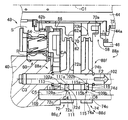
図11は、本発明の他の実施例のトランスファ150を説明する図である。本実施例のトランスファ150は、実施例1のトランスファ22に比較して、伝達機構152の切替機構152aが実施例1の伝達機構88の切替機構88aと異なっている点で相違しており、その他は実施例1のトランスファ22と略同じである。   FIG. 11 is a diagram illustrating a transfer 150 according to another embodiment of the present invention. The transfer 150 of the present embodiment is different from the transfer 22 of the first embodiment in that the switching mechanism 152a of the transmission mechanism 152 is different from the switching mechanism 88a of the transmission mechanism 88 of the first embodiment. Is substantially the same as the transfer 22 of the first embodiment.

伝達機構152には、電動モータ84の回転運動に連動して、ハイロースリーブ62とロックスリーブ70とが、ハイロー切替機構48において高速側ギヤ段Hが成立され且つ後輪側出力軸44とドライブギヤ46とが直結化するH4L位置と、ハイロー切替機構48において低速側ギヤ段Lが成立され且つ後輪側出力軸44とドライブギヤ46とが直結化するL4L位置と、ハイロー切替機構48において高速側ギヤ段Hが成立され且つ後輪側出力軸44とドライブギヤ46とが直結化されないハイギヤ(H4またはH2)位置とに選択的に切り替えられる切替機構152aが、備えられている。また、伝達機構152には、ネジ機構86におけるナット部材92の直線運動を前輪駆動用クラッチ50に伝達する実施例1の第1伝達機構88bと同じ第1伝達機構(伝達機構)152bが備えられている。   In the transmission mechanism 152, the high / low sleeve 62 and the lock sleeve 70 are interlocked with the rotational movement of the electric motor 84, the high speed side gear stage H is established in the high / low switching mechanism 48, and the rear wheel side output shaft 44 and the drive gear are connected. 46, the L4L position where the low-speed gear stage L is established in the high / low switching mechanism 48 and the rear wheel side output shaft 44 and the drive gear 46 are directly connected, and the high / low switching mechanism 48 is the high speed side. A switching mechanism 152a that selectively switches to a high gear (H4 or H2) position where the gear stage H is established and the rear wheel side output shaft 44 and the drive gear 46 are not directly connected is provided. Further, the transmission mechanism 152 includes a first transmission mechanism (transmission mechanism) 152b that is the same as the first transmission mechanism 88b of the first embodiment that transmits the linear motion of the nut member 92 in the screw mechanism 86 to the front wheel drive clutch 50. ing.

切替機構152aには、図11および図12に示すように、後輪側出力軸44と平行に配置され第1軸線C1方向に移動可能にトランスファケース40に支持される第1フォークシャフト(第2軸)154および第2フォークシャフト156と、第1フォークシャフト154に第1待ち機構158を介して連結された第1カム係合部材160と、第2フォークシャフト156に第2待ち機構162を介して連結された第2カム係合部材164と、第1カム係合部材160と係合し後輪側出力軸44の第1軸線C1まわりに回動することにより第1カム係合部材160を第1フォークシャフト154の第7軸線(軸心)C7方向に移動させる第1カム溝100j、および第2カム係合部材164と係合し後輪側出力軸44の第1軸線C1まわりに回動することにより第2カム係合部材164を第2フォークシャフト156の第8軸線(軸心)C8方向に移動させる第2カム溝100kが、外周に形成されたドラムカム100と、第1フォークシャフト154に一体的に固定され、ハイロースリーブ62のフォーク連結部62aに連結されたハイローシフトフォーク166と、第2フォークシャフト156に一体的に固定され、ロックスリーブ70のフォーク連結部70bに連結された4WDロックフォーク168とが備えられている。なお、第1フォークシャフト154の第7軸線C7と第2フォークシャフト156の第8軸線C8とは、後輪側出力軸44の第1軸線C1と平行である。また、第1待ち機構158および第2待ち機構162は、実施例1の待ち機構106の構成と同様であるので、本実施例では第1待ち機構158および第2待ち機構162の構成の説明を省略する。   As shown in FIGS. 11 and 12, the switching mechanism 152a includes a first fork shaft (second shaft) that is arranged in parallel to the rear wheel output shaft 44 and supported by the transfer case 40 so as to be movable in the direction of the first axis C1. Shaft) 154 and a second fork shaft 156, a first cam engagement member 160 connected to the first fork shaft 154 via a first waiting mechanism 158, and a second waiting mechanism 162 to the second fork shaft 156. The first cam engaging member 160 is engaged with the first cam engaging member 160 and the first cam engaging member 160 and rotated about the first axis C1 of the rear wheel output shaft 44. The first fork shaft 154 engages with the first cam groove 100j that moves in the direction of the seventh axis (axial center) C7 and the second cam engagement member 164, and around the first axis C1 of the rear wheel side output shaft 44. The drum cam 100 having a second cam groove 100k formed on the outer periphery thereof for moving the second cam engaging member 164 in the direction of the eighth axis (axial center) C8 of the second fork shaft 156 by rotating, and the first fork A high / low shift fork 166 fixed integrally to the shaft 154 and connected to the fork connecting portion 62a of the high / low sleeve 62, and fixed to the second fork shaft 156 integrally and connected to the fork connecting portion 70b of the lock sleeve 70. And a 4WD lock fork 168. The seventh axis C7 of the first fork shaft 154 and the eighth axis C8 of the second fork shaft 156 are parallel to the first axis C1 of the rear wheel side output shaft 44. Further, the first waiting mechanism 158 and the second waiting mechanism 162 are the same as the configuration of the waiting mechanism 106 of the first embodiment. Therefore, in this embodiment, the configuration of the first waiting mechanism 158 and the second waiting mechanism 162 will be described. Omitted.

図13に示すように、ドラムカム100に形成された第1カム溝100jには、後輪側出力軸44の第1軸線C1に対して傾斜する方向に伸びた傾斜カム溝部100lと、傾斜カム溝部100lの第2カム溝100k側とは反対側の端部に形成され、第1軸線C1に対して垂直方向に伸びた第1カム溝部100mと、傾斜カム溝部100lの第2カム溝100k側の端部に形成され、第1軸線C1方向に対して垂直方向に伸びた第2カム溝部100nとを有している。第1カム溝100jでは、例えば図14の(b)に示すように、第1カム溝100jの第1カム溝部100mにおいて傾斜カム溝部100l側の端部内に第1カム係合部材160が配置された状態から、電動モータ84によってナット部材92が第1軸線C1回り矢印F1方向に回動されると共にドラムカム100が第1軸線C1回り矢印F1方向に回動させられると、第1カム係合部材160が傾斜カム溝部100lに沿ってナット部材92の矢印F2方向の移動量より大きい移動量D1で矢印F2方向に移動させられ、第1フォークシャフト154が矢印F2方向に移動する。また、例えば図14の(c)に示すように、第1カム溝100jの第2カム溝部100n内に第1カム係合部材160が配置された状態から、電動モータ84によってナット部材92が第1軸線C1回り矢印F1方向とは反対方向に回動されると共にドラムカム100が第1軸線C1回り矢印F1方向とは反対方向に回動させられると、第1カム係合部材160が傾斜カム溝部100lに沿ってナット部材92の矢印F2方向とは反対方向の移動量より大き移動量D1で矢印F2方向とは反対方向に移動させられ、第1フォークシャフト154が矢印F2方向とは反対方向に移動する。 As shown in FIG. 13, the first cam groove 100j formed in the drum cam 100 includes an inclined cam groove portion 100l extending in a direction inclined with respect to the first axis C1 of the rear wheel side output shaft 44, and an inclined cam groove portion. The first cam groove portion 100m is formed at the end opposite to the second cam groove 100k side of 100l and extends in the direction perpendicular to the first axis C1, and the second cam groove 100k side of the inclined cam groove portion 100l. The second cam groove portion 100n is formed at the end portion and extends in the direction perpendicular to the first axis C1 direction. In the first cam groove 100j, for example, as shown in FIG. 14B, a first cam engagement member 160 is disposed in the end portion on the inclined cam groove portion 100l side in the first cam groove portion 100m of the first cam groove 100j. When the nut member 92 is rotated about the first axis C1 in the direction of the arrow F1 and the drum cam 100 is rotated about the first axis C1 in the direction of the arrow F1 by the electric motor 84, the first cam engagement member 160 is moved in the direction of arrow F2 by a movement amount D1 larger than the movement amount of the nut member 92 in the direction of arrow F2 along the inclined cam groove portion 100l, and the first fork shaft 154 moves in the direction of arrow F2. For example, as shown in FIG. 14C, the nut member 92 is moved by the electric motor 84 from the state where the first cam engaging member 160 is disposed in the second cam groove portion 100n of the first cam groove 100j. When the drum cam 100 is rotated in the direction opposite to the arrow F1 direction around the first axis C1 and the arrow cam F1 is rotated in the direction opposite to the arrow F1 direction, the first cam engaging member 160 is inclined cam groove. the arrow F2 direction is indicated by an arrow F2 direction movement amount not greater than the movement amount in the opposite direction D1 of the nut member 92 along the 100l is moved in the opposite direction, a direction opposite to the first fork shaft 154 is the direction of the arrow F2 Move to.

なお、第1カム溝100jでは、例えば図14の(a)に示すように第1カム溝100jの第1カム溝部100mにおいて傾斜カム溝部100l側とは反対側の端部内に第1カム係合部材160が配置された状態から、図14の(b)に示すように第1カム係合部材160が第1カム溝部100mの傾斜カム溝部100l側の端部に配置されるように、電動モータ84によってドラムカム100が第1軸線C1回り矢印F1方向に回動させられても、第1カム係合部材160が矢印F2方向に移動しない。また、例えば図14の(b)に示すように第1カム溝100jの第1カム溝部100mにおいて傾斜カム溝部100l側の端部内に第1カム係合部材160が配置された状態から、図14の(a)に示すように第1カム係合部材160が第1カム溝部100mの傾斜カム溝部100l側とは反対側の端部に配置されるように、電動モータ84によってドラムカム100が第1軸線C1回り矢印方向とは反対方向に回動させられても、第1カム係合部材160が矢印F2方向とは反対方向に移動しない。   In the first cam groove 100j, for example, as shown in FIG. 14 (a), the first cam engagement is in the end of the first cam groove 100m of the first cam groove 100j opposite to the inclined cam groove 100l side. From the state in which the member 160 is disposed, the electric motor is arranged such that the first cam engaging member 160 is disposed at the end of the first cam groove portion 100m on the inclined cam groove portion 100l side as shown in FIG. 14 (b). Even if the drum cam 100 is rotated about the first axis C1 in the direction of arrow F1 by 84, the first cam engagement member 160 does not move in the direction of arrow F2. Further, for example, as shown in FIG. 14B, the first cam engaging member 160 is disposed in the end portion on the inclined cam groove portion 100l side in the first cam groove portion 100m of the first cam groove 100j. As shown in FIG. 4A, the drum cam 100 is moved by the electric motor 84 so that the first cam engaging member 160 is disposed at the end of the first cam groove portion 100m opposite to the inclined cam groove portion 100l. Even if the first cam engagement member 160 is rotated in the direction opposite to the arrow direction around the axis C1, the first cam engagement member 160 does not move in the direction opposite to the arrow F2 direction.

図13に示すように、ドラムカム100に形成された第2カム溝100kには、後輪側出力軸44の第1軸線C1に対して傾斜する方向に伸びた傾斜カム溝部100oと、傾斜カム溝部100oの第1カム溝100j側の端部に形成され、第1軸線C1方向に対して垂直方向に伸びた第1カム溝部100pと、傾斜カム溝部100oの第1カム溝100j側とは反対側の端部に形成され、第1軸線C1方向に対して垂直方向に伸びた第2カム溝部100qとを有している。第2カム溝100kでは、例えば図14の(a)に示すように、第2カム溝100kの第1カム溝部100p内に第2カム係合部材164が配置された状態から、電動モータ84によってナット部材92が第1軸線C1回り矢印F1方向に回動されると共にドラムカム100が第1軸線C1回り矢印F1方向に回動させられると、第2カム係合部材164が傾斜カム溝部100oに沿ってナット部材92の矢印F2方向の移動量より大きい移動量D2で矢印F2方向に移動させられ、第2フォークシャフト156が矢印F2方向に移動する。また、例えば図14の(b)に示すように、第2カム溝100kの第2カム溝部100qにおいて傾斜カム溝部100o側の端部内に第2カム係合部材164が配置された状態から、電動モータ84によってナット部材92が第1軸線C1回り矢印F1方向とは反対方向に回動されると共にドラムカム100が第1軸線C1回り矢印F1方向とは反対方向に回動させられると、第2カム係合部材164が傾斜カム溝部100oに沿ってナット部材92の矢印F2方向とは反対方向の移動量より大き移動量D2で矢印F2方向とは反対方向に移動させられ、第2フォークシャフト156が矢印F2方向とは反対方向に移動する。 As shown in FIG. 13, the second cam groove 100k formed in the drum cam 100 includes an inclined cam groove portion 100o extending in a direction inclined with respect to the first axis C1 of the rear wheel side output shaft 44, and an inclined cam groove portion. The first cam groove portion 100p formed at the end portion of the first cam groove 100j side of 100o and extending in the direction perpendicular to the first axis C1 direction is opposite to the first cam groove 100j side of the inclined cam groove portion 100o. And a second cam groove portion 100q extending in a direction perpendicular to the first axis C1 direction. In the second cam groove 100k, for example, as shown in FIG. 14A, the electric motor 84 starts from the state where the second cam engagement member 164 is disposed in the first cam groove portion 100p of the second cam groove 100k. When the nut member 92 is rotated about the first axis C1 in the direction of the arrow F1 and the drum cam 100 is rotated about the first axis C1 in the direction of the arrow F1, the second cam engagement member 164 is moved along the inclined cam groove portion 100o. Thus, the nut member 92 is moved in the arrow F2 direction by a movement amount D2 that is larger than the movement amount in the arrow F2 direction, and the second fork shaft 156 moves in the arrow F2 direction. Further, for example, as shown in FIG. 14 (b), the second cam engagement member 164 is disposed in the end portion on the inclined cam groove portion 100o side in the second cam groove portion 100q of the second cam groove 100k. When the nut member 92 is rotated by the motor 84 in the direction opposite to the arrow F1 direction around the first axis C1, and the drum cam 100 is rotated in the direction opposite to the arrow F1 direction around the first axis C1, the second cam the engaging member 164 and the arrow F2 direction of the nut member 92 along the inclined cam groove portions 100o are moved in the direction opposite to the arrow F2 direction movement amount D2 have larger than the moving amount in the opposite direction, a second fork shaft 156 Moves in the direction opposite to the arrow F2 direction.

なお、第2カム溝100kでは、例えば図14の(b)に示すように第2カム溝100kの第2カム溝部100qにおいて傾斜カム溝部100o側の端部内に第2カム係合部材164が配置された状態から、図14の(c)に示すように第2カム係合部材164が第2カム溝部100qの傾斜カム溝部100o側とは反対側の端部に配置されるように、電動モータ84によってドラムカム100が第1軸線C1回り矢印F1方向に回動させられても、第2カム係合部材164が矢印F2方向に移動しない。また、例えば図14の(c)に示すように第2カム溝100kの第2カム溝部100qにおいて傾斜カム溝部100o側とは反対側の端部内に第2カム係合部材164が配置された状態から、図14の(b)に示すように第2カム係合部材164が第2カム溝部100qの傾斜カム溝部100o側の端部に配置されるように、電動モータ84によってドラムカム100が第1軸線C1回り矢印方向とは反対方向に回動させられても、第2カム係合部材164が矢印F2方向とは反対方向に移動しない。   In the second cam groove 100k, for example, as shown in FIG. 14B, the second cam engagement member 164 is disposed in the end portion on the inclined cam groove portion 100o side in the second cam groove portion 100q of the second cam groove 100k. As shown in FIG. 14C, the electric motor is arranged such that the second cam engagement member 164 is disposed at the end of the second cam groove portion 100q opposite to the inclined cam groove portion 100o. Even if the drum cam 100 is rotated about the first axis C1 in the direction of arrow F1 by 84, the second cam engagement member 164 does not move in the direction of arrow F2. Further, for example, as shown in FIG. 14C, the second cam engaging member 164 is disposed in the end portion of the second cam groove 100k opposite to the inclined cam groove portion 100o in the second cam groove portion 100q. 14 (b), the drum cam 100 is moved by the electric motor 84 so that the second cam engaging member 164 is disposed at the end of the second cam groove portion 100q on the inclined cam groove portion 100o side. Even if the second cam engagement member 164 is rotated in the direction opposite to the arrow direction around the axis C1, the second cam engagement member 164 does not move in the direction opposite to the arrow F2 direction.

図13に示すように、ドラムカム100に形成された第1カム溝100jおよび第2カム溝100kは、矢印F1方向において第2カム溝100k、第1カム溝100jの順で配置している。すなわち、第1カム溝100jと第2カム溝100kとは、第1カム溝100jの第2カム溝100k側とは反対側の端A1と第2カム溝100kの第1カム溝100j側の端A2とが図12に示すように所定角度θだけずらされて配置されている。   As shown in FIG. 13, the first cam groove 100j and the second cam groove 100k formed in the drum cam 100 are arranged in the order of the second cam groove 100k and the first cam groove 100j in the arrow F1 direction. That is, the first cam groove 100j and the second cam groove 100k are an end A1 of the first cam groove 100j opposite to the second cam groove 100k side and an end of the second cam groove 100k on the first cam groove 100j side. A2 and A2 are shifted by a predetermined angle θ as shown in FIG.

図14は、仮想的にドラムカム100に形成された第2カム溝100kを矢印F1方向所定角度θだけ回動させ第1カム溝100jと第2カム溝100kとを第1軸線C1方向に並べた図、すなわち仮想的に第1カム溝100jの第2カム溝100k側とは反対側の端A1と第2カム溝100kの第1カム溝100j側の端A2とが矢印F1方向で一致するように第2カム溝100kを回動させ第1カム溝100jと第2カム溝100kとを第1軸線C1方向に並べた図である。なお、図14において、図14の(a)は、ハイロースリーブ62およびロックスリーブ70がハイギヤ(H4またはH2)位置に切り替えられた、すなわちドラムカム100がハイギヤ(H4またはH2)位置に回動させられた時における第1カム係合部材160および第2カム係合部材164の位置を示す図である。また、図14の(b)は、ハイロースリーブ62およびロックスリーブ70がH4L位置に切り替えられた、すなわちドラムカム100がH4L位置に回動させられた時における第1カム係合部材160および第2カム係合部材164の位置を示す図である。また、図14の(c)は、ハイロースリーブ62およびロックスリーブ70がL4L位置に切り替えられた、すなわちドラムカム100がL4L位置に回動させられた時における第1カム係合部材160および第2カム係合部材164の位置を示す図である。   In FIG. 14, the second cam groove 100k virtually formed in the drum cam 100 is rotated by a predetermined angle θ in the direction of arrow F1, and the first cam groove 100j and the second cam groove 100k are arranged in the first axis C1 direction. In the drawing, that is, the end A1 of the first cam groove 100j opposite to the second cam groove 100k side and the end A2 of the second cam groove 100k on the first cam groove 100j side are aligned with each other in the direction of the arrow F1. The second cam groove 100k is rotated and the first cam groove 100j and the second cam groove 100k are arranged in the direction of the first axis C1. 14, (a) in FIG. 14 shows that the high / low sleeve 62 and the lock sleeve 70 are switched to the high gear (H4 or H2) position, that is, the drum cam 100 is rotated to the high gear (H4 or H2) position. It is a figure which shows the position of the 1st cam engagement member 160 and the 2nd cam engagement member 164 at the time. 14B shows the first cam engaging member 160 and the second cam when the high / low sleeve 62 and the lock sleeve 70 are switched to the H4L position, that is, when the drum cam 100 is rotated to the H4L position. It is a figure which shows the position of the engaging member. FIG. 14C shows the first cam engaging member 160 and the second cam when the high / low sleeve 62 and the lock sleeve 70 are switched to the L4L position, that is, when the drum cam 100 is rotated to the L4L position. It is a figure which shows the position of the engaging member.

以上のように構成されたトランスファ150によれば、電動モータ84が回転駆動することによってネジ機構86を介してドラムカム100が図14の(a)および図14の(b)に示すようにハイギヤ位置からH4L位置に回動させられると、第2カム係合部材164が傾斜カム溝部100oに沿って矢印F2方向に移動すると共にロックスリーブ70が第2フォークシャフト156および4WDロックフォーク168を介して矢印F2方向に移動して、ロックスリーブ70の噛合歯70aがロック歯68に噛み合う。なお、ドラムカム100がハイギヤ位置からH4L位置に回動しても、第1カム係合部材160は第1カム溝部100mに沿って移動し矢印F2方向に移動しないので、ハイロースリーブ62の外周歯62bはハイ側ギヤ歯64に噛み合ったままである。このため、ドラムカム100がハイギヤ位置からH4L位置に回動させられると、ロックスリーブ70がH4L位置に切り替えられる。   According to the transfer 150 configured as described above, the drum cam 100 is moved to the high gear position as shown in FIGS. 14A and 14B through the screw mechanism 86 by the electric motor 84 being rotationally driven. When the second cam engaging member 164 is moved in the direction of arrow F2 along the inclined cam groove 100o, the lock sleeve 70 is moved through the second fork shaft 156 and the 4WD lock fork 168. Moving in the direction F <b> 2, the meshing teeth 70 a of the lock sleeve 70 mesh with the lock teeth 68. Even if the drum cam 100 is rotated from the high gear position to the H4L position, the first cam engagement member 160 moves along the first cam groove portion 100m and does not move in the direction of the arrow F2. Remains engaged with the high-side gear teeth 64. For this reason, when the drum cam 100 is rotated from the high gear position to the H4L position, the lock sleeve 70 is switched to the H4L position.

また、ドラムカム100が図14の(b)および図14の(c)に示すようにH4L位置からL4L位置に回動させられると、第1カム係合部材160が傾斜カム溝部100lに沿って矢印F2方向に移動すると共にハイロースリーブ62が第1フォークシャフト154およびハイローシフトフォーク166を介して矢印F2方向に移動して、ハイロースリーブ62の外周歯62bがロー側ギヤ歯66に噛み合う。なお、ドラムカム100がH4L位置からL4L位置に回動しても、第2カム係合部材164は第2カム溝部100qに沿って移動し矢印F2方向に移動しないので、ロックスリーブ70の噛合歯70aはロック歯68に噛み合ったままである。このため、ドラムカム100がH4L位置からL4L位置に回動させられると、ハイロースリーブ62がL4L位置に切り替えられる。   When the drum cam 100 is rotated from the H4L position to the L4L position as shown in FIGS. 14B and 14C, the first cam engagement member 160 is moved along the inclined cam groove portion 100l by the arrow. While moving in the F2 direction, the high / low sleeve 62 moves in the direction of the arrow F2 via the first fork shaft 154 and the high / low shift fork 166, and the outer peripheral teeth 62b of the high / low sleeve 62 mesh with the low-side gear teeth 66. Even if the drum cam 100 rotates from the H4L position to the L4L position, the second cam engagement member 164 moves along the second cam groove portion 100q and does not move in the direction of the arrow F2. Remains engaged with the lock teeth 68. For this reason, when the drum cam 100 is rotated from the H4L position to the L4L position, the high / low sleeve 62 is switched to the L4L position.

また、ドラムカム100が図14の(c)および図14の(b)に示すようにL4L位置からH4L位置に回動させられると、第1カム係合部材160が傾斜カム溝部100lに沿って矢印F2方向とは反対方向に移動すると共にハイロースリーブ62が第1フォークシャフト154およびハイローシフトフォーク166を介して矢印F2方向とは反対方向に移動して、ハイロースリーブ62の外周歯62bがハイ側ギヤ歯64に噛み合う。なお、ドラムカム100がL4L位置からH4L位置に回動しても、第2カム係合部材164は第2カム溝部100qに沿って移動し矢印F2方向とは反対方向に移動しないので、ロックスリーブ70の噛合歯70aはロック歯68に噛み合ったままである。このため、ドラムカム100がL4L位置からH4L位置に回動させられると、ハイロースリーブ62がH4L位置に切り替えられる。   When the drum cam 100 is rotated from the L4L position to the H4L position as shown in FIGS. 14C and 14B, the first cam engagement member 160 is moved along the inclined cam groove portion 100l by the arrow. The high / low sleeve 62 moves in the direction opposite to the direction of the arrow F2 via the first fork shaft 154 and the high / low shift fork 166, and the outer peripheral teeth 62b of the high / low sleeve 62 move to the high side gear. Engages with teeth 64. Even if the drum cam 100 rotates from the L4L position to the H4L position, the second cam engagement member 164 moves along the second cam groove portion 100q and does not move in the direction opposite to the arrow F2 direction. The meshing teeth 70 a remain meshed with the lock teeth 68. For this reason, when the drum cam 100 is rotated from the L4L position to the H4L position, the high / low sleeve 62 is switched to the H4L position.

また、ドラムカム100が図14の(b)および図14の(a)に示すようにH4L位置からハイギヤ位置に回動させられると、第2カム係合部材164が傾斜カム溝部100oに沿って矢印F2方向とは反対方向に移動すると共にロックスリーブ70が第2フォークシャフト156および4WDロックフォーク168を介して矢印F2方向とは反対方向に移動して、ロックスリーブ70の噛合歯70aがロック歯68から離れ噛み合わなくなる。なお、ドラムカム100がH4L位置からハイギヤ位置に回動しても、第1カム係合部材160は第1カム溝部100mに沿って移動し矢印F2方向とは反対方向に移動しないので、ハイロースリーブ62の外周歯62bはハイ側ギヤ歯64に噛み合ったままである。このため、ドラムカム100がH4L位置からハイギヤ位置に回動させられると、ハイロースリーブ62およびロックスリーブ70がハイギヤ位置に切り替えられる。   When the drum cam 100 is rotated from the H4L position to the high gear position as shown in FIGS. 14B and 14A, the second cam engagement member 164 is moved along the inclined cam groove portion 100o by the arrow. The lock sleeve 70 moves in the direction opposite to the F2 direction, and the lock sleeve 70 moves in the direction opposite to the arrow F2 direction via the second fork shaft 156 and the 4WD lock fork 168. Away from meshing. Even if the drum cam 100 rotates from the H4L position to the high gear position, the first cam engagement member 160 moves along the first cam groove portion 100m and does not move in the direction opposite to the arrow F2 direction. The outer peripheral teeth 62 b remain engaged with the high-side gear teeth 64. Therefore, when the drum cam 100 is rotated from the H4L position to the high gear position, the high / low sleeve 62 and the lock sleeve 70 are switched to the high gear position.

以上、本発明の実施例を図面に基づいて詳細に説明したが、本発明はその他の態様においても適用される。   As mentioned above, although the Example of this invention was described in detail based on drawing, this invention is applied also in another aspect.

例えば、前述の実施例1において、ネジ機構86では、ナット部材92が電動モータ84により回転駆動されることによって、ナット部材92が後輪側出力軸44の第1軸線C1方向に移動させられていたが、例えば、ネジ軸部材94が電動モータ84により回転駆動されることによって、ナット部材92が後輪側出力軸44の第1軸線C1方向に移動させられるようにネジ機構86の構造を変更しても良い。なお、このように、ネジ軸部材94が電動モータ84によって回転駆動される場合には、ナット部材92は、後輪側出力軸44の第1軸線C1方向に移動可能且つ第1軸線C1まわりに回転不能にケース等に支持され、ネジ軸部材94は後輪側出力軸44の第1軸線C1方向に移動不能に、かつ後輪側出力軸44の第1軸線C1まわりに回転可能に後輪側出力軸44に支持される。また、ネジ軸部材94にドラムカム100が連結される。これによって、電動モータ84によってネジ軸部材94が回転駆動させられると、ナット部材92が後輪側出力軸44の第1軸線C1方向に移動してナット部材92の直線運動が第1伝達機構88bを介して前輪駆動用クラッチ50に伝達される。さらに、電動モータ84によってネジ軸部材94が回転駆動させられると、ネジ軸部材94に連結されたドラムカム100が回動しカム溝100cに係合されたカム係合部材103がフォークシャフト102の第3軸線C3方向に移動してカム係合部材103の直線運動すなわちフォークシャフト102の直線運動が第1移動機構88eおよび第2移動機構88fを介してハイロー切替機構48と4WDロック機構58とに択一的に伝達される。   For example, in the first embodiment, in the screw mechanism 86, the nut member 92 is moved in the direction of the first axis C <b> 1 of the rear wheel side output shaft 44 by the rotation of the nut member 92 by the electric motor 84. However, for example, the structure of the screw mechanism 86 is changed so that the nut member 92 is moved in the direction of the first axis C1 of the rear wheel side output shaft 44 when the screw shaft member 94 is rotationally driven by the electric motor 84. You may do it. When the screw shaft member 94 is rotationally driven by the electric motor 84 as described above, the nut member 92 is movable in the direction of the first axis C1 of the rear wheel side output shaft 44 and around the first axis C1. The screw shaft member 94 is supported by a case or the like so as not to rotate. The screw shaft member 94 cannot move in the direction of the first axis C1 of the rear wheel side output shaft 44 and can rotate about the first axis C1 of the rear wheel side output shaft 44. It is supported by the side output shaft 44. The drum cam 100 is connected to the screw shaft member 94. Thus, when the screw shaft member 94 is driven to rotate by the electric motor 84, the nut member 92 moves in the direction of the first axis C1 of the rear wheel side output shaft 44, and the linear movement of the nut member 92 causes the first transmission mechanism 88b. Is transmitted to the front-wheel drive clutch 50 via. Further, when the screw shaft member 94 is rotationally driven by the electric motor 84, the drum cam 100 connected to the screw shaft member 94 is rotated and the cam engagement member 103 engaged with the cam groove 100c is moved to the fork shaft 102. The linear movement of the cam engaging member 103, that is, the linear movement of the fork shaft 102 is moved to the three axis C3 direction, and the high / low switching mechanism 48 and the 4WD lock mechanism 58 are selected via the first moving mechanism 88e and the second moving mechanism 88f. Communicated in one piece.

また、前述の実施例1において、第1インターロック部材111の一端部111a、他端部111bおよび第2インターロック部材115の一端部115a、他端部115bは球面状であったが、例えば第1インターロック部材111の軸部111cおよび第2インターロック部材115の軸部115cは四角柱状でその両端の一端部111a、他端部111bおよび一端部115a、他端部115bは、部分円柱状の凸曲面が形成されるような形状であっても良い。また、第1インターロック部材111の一端部111a、他端部111bおよび第2インターロック部材115の一端部115a、他端部115bは、一対の平坦な傾斜面がそれぞれ形成されるような形状であっても良い。すなわち、フォークシャフト102が移動して、フォークシャフト102の凹部(第1凹部102a、第2凹部102b)の開口端部にインターロック部材(第1インターロック部材111、第2インターロック部材115)のフォークシャフト102側の一端部111a、115aが当接するとその一端部111a、115aに固定軸109に接近する方向の推力が発生させられ、且つ固定軸109の凹部(第2凹部109a、第2凹部109b)の開口端部にインターロック部材(第1インターロック部材111、第2インターロック部材115)の固定軸109側の他端部111b、115bが当接するとその他端部111b、115bにフォークシャフト102に接近する方向の推力が発生させられるのであれば、第1インターロック部材111の一端部111a,他端部111bの形状、第2インターロック部材115の一端部115a,他端部115bの形状、フォークシャフト102に凹んだ第1凹部102a,第2凹部102aの形状、および固定軸109に凹んだ第1凹部109a,第2凹部109bの形状は、どのような形状であっても良い。例えば、第1インターロック部材111、第2インターロック部材115が球形状であっても良い。   In the first embodiment, the one end 111a and the other end 111b of the first interlock member 111 and the one end 115a and the other end 115b of the second interlock member 115 are spherical. The shaft portion 111c of the first interlock member 111 and the shaft portion 115c of the second interlock member 115 have a quadrangular prism shape, and one end portion 111a, the other end portion 111b, one end portion 115a, and the other end portion 115b at both ends thereof are partially cylindrical. The shape may be such that a convex curved surface is formed. In addition, the one end 111a and the other end 111b of the first interlock member 111 and the one end 115a and the other end 115b of the second interlock member 115 are each formed with a pair of flat inclined surfaces. There may be. That is, the fork shaft 102 moves, and the interlock members (the first interlock member 111 and the second interlock member 115) are formed at the opening ends of the recesses (the first recess 102a and the second recess 102b) of the fork shaft 102. When the one end portions 111a and 115a on the fork shaft 102 side come into contact with each other, a thrust in a direction approaching the fixed shaft 109 is generated at the one end portions 111a and 115a, and the concave portions (second concave portion 109a and second concave portion) of the fixed shaft 109 are generated. 109b) when the other end portions 111b and 115b of the interlock member (the first interlock member 111 and the second interlock member 115) on the fixed shaft 109 side come into contact with the other end portions 111b and 115b. If thrust in a direction approaching 102 is generated, the first interlock The shape of one end 111a and the other end 111b of the member 111, the shape of the one end 115a and the other end 115b of the second interlock member 115, the shape of the first recess 102a and the second recess 102a recessed in the fork shaft 102, The shapes of the first recess 109a and the second recess 109b that are recessed in the fixed shaft 109 may be any shape. For example, the first interlock member 111 and the second interlock member 115 may be spherical.

また、前述の実施例1において、ネジ機構86としてボールネジを例示したが、この態様に限らない。例えば、ネジ機構86は、電動モータ84の回転運動を直線運動に変換する変換機構であれば良く、直接的に相互に螺合する単純なネジ軸部材94とナット部材92とを組み合わせたような機構であっても良い。具体的には、ネジ機構86は、すべりねじなどであっても良い。すべりねじの場合には、ボールネジと比較して回転運動を直線運動に変換する機械効率が低くされるが、前輪駆動用クラッチ50へ高い推力を付与することができたり、ハイロー切替機構48の作動に必要なストロークを得ることができるという、一定の効果は得られる。   In the first embodiment, the ball screw is exemplified as the screw mechanism 86, but the present invention is not limited to this. For example, the screw mechanism 86 may be a conversion mechanism that converts the rotational motion of the electric motor 84 into a linear motion, such as a combination of a simple screw shaft member 94 and a nut member 92 that are directly screwed together. It may be a mechanism. Specifically, the screw mechanism 86 may be a slide screw or the like. In the case of a slide screw, the mechanical efficiency of converting rotational motion into linear motion is lower than that of a ball screw. However, high thrust can be applied to the front wheel drive clutch 50, and the high / low switching mechanism 48 can be operated. A certain effect that a necessary stroke can be obtained is obtained.

また、前述の実施例1では、ネジ機構86はウォームギヤ90を介して電動モータ84に間接的に連結されたが、この態様に限らない。例えば、ネジ機構86のナット部材92と電動モータ84とは、ウォームギヤ90を介すことなく直接的に連結されても良い。具体的には、ナット部材92と電動モータ84とは、電動モータ84のモータシャフトに設けられたピニオンとナット部材92に形成されたギヤ歯とが噛み合うように、直接的に連結されても良い。   In the first embodiment, the screw mechanism 86 is indirectly connected to the electric motor 84 via the worm gear 90, but the present invention is not limited to this mode. For example, the nut member 92 of the screw mechanism 86 and the electric motor 84 may be directly connected without using the worm gear 90. Specifically, the nut member 92 and the electric motor 84 may be directly coupled so that a pinion provided on the motor shaft of the electric motor 84 and a gear tooth formed on the nut member 92 are engaged with each other. .

また、前述の実施例1では、トランスファ22が適用される車両10としてFRをベースとする4輪駆動車両を例示したが、これに限らない。例えば、トランスファ22が適用される車両10は、前置エンジン前輪駆動(FF)をベースとする4輪駆動車両であっても良い。また、前輪駆動用クラッチ50は、多板のクラッチであったが、単板のクラッチであっても本発明は適用され得る。   In the first embodiment described above, the four-wheel drive vehicle based on FR is exemplified as the vehicle 10 to which the transfer 22 is applied, but is not limited thereto. For example, the vehicle 10 to which the transfer 22 is applied may be a four-wheel drive vehicle based on a front engine front wheel drive (FF). Further, although the front-wheel drive clutch 50 is a multi-plate clutch, the present invention can be applied to a single-plate clutch.

また、前述の実施例1において、駆動力源として例示したエンジン12は、例えばガソリンエンジンやディーゼルエンジン等の内燃機関が用いられる。また、駆動力源としては、例えば電動機等の他の原動機を単独で或いはエンジン12と組み合わせて採用することもできる。また、変速機20は、遊星歯車式多段変速機、無段変速機、同期噛合型平行2軸式変速機(公知のDCT含む)などの種々の自動変速機、又は公知の手動変速機である。また、フロント側クラッチ36は、電磁ドグクラッチであったが、これに限らない。例えば、フロント側クラッチ36は、スリーブを軸方向に移動させるシフトフォークを備え、電気制御可能な或いは油圧制御可能なアクチュエータによって、そのシフトフォークが駆動される形式のドグクラッチ、又は、摩擦クラッチなどであっても良い。   In the first embodiment, the engine 12 exemplified as the driving force source is, for example, an internal combustion engine such as a gasoline engine or a diesel engine. Further, as the driving force source, for example, another prime mover such as an electric motor can be used alone or in combination with the engine 12. The transmission 20 is a variety of automatic transmissions such as a planetary gear type multi-stage transmission, a continuously variable transmission, a synchronous mesh parallel two-shaft transmission (including a known DCT), or a known manual transmission. . Moreover, although the front side clutch 36 was an electromagnetic dog clutch, it is not restricted to this. For example, the front clutch 36 includes a shift fork that moves the sleeve in the axial direction, and is a dog clutch or a friction clutch that is driven by an electrically controllable or hydraulically controllable actuator. May be.

尚、上述したのはあくまでも一実施形態であり、本発明は当業者の知識に基づいて種々の変更、改良を加えた態様で実施することができる。   The above description is only an embodiment, and the present invention can be implemented in variously modified and improved forms based on the knowledge of those skilled in the art.

22、150:トランスファ
42:入力軸
44:後輪側出力軸(出力軸)
46:ドライブギヤ(出力部材)
48:ハイロー切替機構
50:前輪駆動用クラッチ(クラッチ)
62:ハイロースリーブ
70:ロックスリーブ
72、166:ハイローシフトフォーク
72b、72c:一対の貫通孔
72d:連通孔
73:第2支持ベアリング(出力軸支持ベアリング)
74:4WDロックフォーク
74b、74c:一対の貫通孔
74d:連通孔
84:電動モータ(電動機)
86:ネジ機構
88a、152a:切替機構
88b:第1伝達機構(伝達機構)
92:ナット部材(一方のネジ部材)
94:ネジ軸部材
96:ボール
100:ドラムカム
100c:カム溝
100d:傾斜カム溝部
102:フォークシャフト(第2軸)
102a:第1凹部(凹部)
102b:第2凹部(凹部)
103:カム係合部材
109:固定軸
109a:第1凹部(凹部)
109b:第2凹部(凹部)
111:第1インターロック部材(インターロック部材)
111a:一端部
111b:他端部
112:バネ部材
113:第1ストッパー(ストッパー)
115:第2インターロック部材(インターロック部材)
115a:一端部
115b:他端部
116:第2ストッパー(ストッパー)
C1:第1軸線(軸心)
C3:第3軸線(軸心)
C4:第4軸線(軸心)
C6:第6軸線(軸心)
D:移動量
H:高速側ギヤ段
L:低速側ギヤ段
22, 150: Transfer 42: Input shaft 44: Rear wheel side output shaft (output shaft)
46: Drive gear (output member)
48: High / low switching mechanism 50: Front wheel drive clutch (clutch)
62: high / low sleeve 70: lock sleeve 72, 166: high / low shift forks 72b, 72c: pair of through holes 72d: communication hole 73: second support bearing (output shaft support bearing)
74: 4WD lock forks 74b, 74c: A pair of through holes 74d: Communication holes 84: Electric motor (electric motor)
86: Screw mechanism 88a, 152a: Switching mechanism 88b: First transmission mechanism (transmission mechanism)
92: Nut member (one screw member)
94: Screw shaft member 96: Ball 100: Drum cam 100c: Cam groove 100d: Inclined cam groove portion 102: Fork shaft (second shaft)
102a: 1st recessed part (recessed part)
102b: 2nd recessed part (recessed part)
103: Cam engaging member 109: Fixed shaft 109a: First recess (recess)
109b: second recess (recess)
111: 1st interlock member (interlock member)
111a: one end 111b: the other end 112: spring member 113: first stopper (stopper)
115: Second interlock member (interlock member)
115a: one end 115b: the other end 116: second stopper (stopper)
C1: First axis (axis)
C3: Third axis (axis)
C4: Fourth axis (axis)
C6: 6th axis (axis)
D: Travel distance H: High speed gear stage L: Low speed gear stage

Claims (8)

軸心を共有する入力軸および出力軸と、前記入力軸に連結され、ハイロースリーブが前記出力軸の軸心方向に移動されることによって、前記入力軸の回転を変速して前記出力軸に伝達するハイロー切替機構と、前記出力軸とは動力の出力先を別にする出力部材と、前記出力軸の動力の一部を調整して前記出力部材に伝達するクラッチと、前記出力軸にその軸心方向に移動可能且つその軸心まわりに相対回転不能に支持され前記出力部材に選択的に嵌合し、前記出力軸と前記出力部材とを直結化するロックスリーブと、前記出力軸に支持され、互いに螺合するネジ軸部材およびナット部材のいずれか一方のネジ部材が電動機により回転駆動されることによって、前記ナット部材を、前記出力軸の軸心方向に移動させるネジ機構と、前記ネジ機構における前記ナット部材の直線運動を前記クラッチに伝達する伝達機構と、を備える4輪駆動車両用トランスファであって、
前記電動機の回転運動を前記出力軸の軸心方向の直線運動に変換するドラムカムと、
前記電動機の回転運動に連動して、前記ドラムカムにより変換される前記直線運動をハイローシフトフォークおよび4WDロックフォークが前記ハイロースリーブおよび前記ロックスリーブにそれぞれ伝達することによって、前記ハイロースリーブおよび前記ロックスリーブを、前記ハイロー切替機構において高速側ギヤ段が成立され且つ前記出力軸と前記出力部材とが直結化するH4L位置と、前記ハイロー切替機構において低速側ギヤ段が成立され且つ前記出力軸と前記出力部材とが直結化するL4L位置とに選択的に切り替える切替機構が、備えられていることを特徴とする4輪駆動車両用トランスファ。
An input shaft and an output shaft sharing a shaft center, and a high / low sleeve connected to the input shaft and moved in the axial direction of the output shaft, thereby shifting the rotation of the input shaft and transmitting it to the output shaft. A high / low switching mechanism, an output member that separates the output destination of the power from the output shaft, a clutch that adjusts a part of the power of the output shaft and transmits the power to the output member, and an axial center of the output shaft A lock sleeve that is movable in the direction and supported around the shaft center so as not to rotate relative to the output member and is selectively fitted to the output member, and is directly supported by the output shaft and the output member, and is supported by the output shaft, A screw mechanism that moves the nut member in the axial direction of the output shaft by rotating one of the screw shaft member and the nut member that are screwed together by an electric motor, and the screw mechanism A transmission mechanism for transmitting the linear motion of definitive said nut member to said clutch, a transfer for four-wheel drive vehicle equipped with,
A drum cam that converts the rotational motion of the electric motor into linear motion in the axial direction of the output shaft;
The high / low shift fork and the 4WD lock fork transmit the linear motion converted by the drum cam to the high / low sleeve and the lock sleeve, respectively , in conjunction with the rotational motion of the electric motor. the Hi-Lo in the switching mechanism and a high speed side gear stage is established and the output shaft and the output member and the H4L position to direct reduction, the HiLo in the switching mechanism low-speed side gear stage is established and the output member and the output shaft Doo is selectively switched Ell and switching mechanism, four-wheel drive vehicle for transfer, characterized in that provided in the L4L position directly of.
前記出力軸と平行に配置され軸心方向に移動可能に支持される第2軸を備え、A second shaft disposed parallel to the output shaft and supported so as to be movable in the axial direction;
前記ハイローシフトフォークおよび前記4WDロックフォークは、それぞれ前記第2軸に択一的に係合され、The high / low shift fork and the 4WD lock fork are each selectively engaged with the second shaft,
前記切替機構は、前記第2軸の軸心方向の移動を前記ハイローシフトフォークおよび前記4WDロックフォークにより前記ハイロースリーブおよび前記ロックスリーブにそれぞれ伝達する請求項1の4輪駆動車両用トランスファ。The four-wheel drive vehicle transfer according to claim 1, wherein the switching mechanism transmits movement of the second shaft in the axial direction to the high / low sleeve and the lock sleeve by the high / low shift fork and the 4WD lock fork, respectively.
前記切替機構は、前記第2軸と平行に配置された固定軸と、前記ハイローシフトフォークと前記4WDロックフォークとにそれぞれ形成され、前記第2軸と前記固定軸とをその軸心方向に移動可能に貫通させた一対の貫通孔と、前記ハイローシフトフォークの一対の貫通孔間と前記4WDロックフォークの一対の貫通孔間とにそれぞれ形成され、それら一対の貫通孔間を連通する連通孔と、前記連通孔のそれぞれの内部にそれぞれ配置された第1インターロック部材および第2インターロック部材と、前記第2軸と前記固定軸とにそれぞれ形成され、前記第1インターロック部材の一端部と他端部とが選択的に係合される一対の第1凹部と、前記第2軸と前記固定軸とにそれぞれ形成され、前記第2インターロック部材の一端部と他端部とが選択的に係合される一対の第2凹部と、前記第2軸に形成されその軸心方向の移動により前記ハイローシフトフォークを選択的に軸心方向に移動させる第1ストッパーと、前記第2軸に形成され、その軸心方向の移動により前記4WDロックフォークを選択的に軸心方向に移動させる第2ストッパーとを備えており、
前記切替機構は、前記第1ストッパーおよび前記第2ストッパー前記第1インターロック部材および前記第2インターロック部材によって、前記第2軸と前記ハイローシフトフォーク、および前記第2軸と前記4WDロックフォークを択一的に係合して、前記第2軸の移動を前記ハイローシフトフォークまたは前記4WDロックフォークに択一的に伝達するインターロック機能を有することを特徴とする請求項の4輪駆動車両用トランスファ。
The switching mechanism is moved, the second axis disposed parallel to the fixed shaft, wherein respectively formed on the high-low shift fork and the 4WD lock fork, and said fixed shaft and said second shaft in its axial direction A pair of through holes pierced in a possible manner, a communication hole formed between the pair of through holes of the high / low shift fork and the pair of through holes of the 4WD lock fork, respectively, and communicating between the pair of through holes; A first interlock member and a second interlock member respectively disposed in each of the communication holes, the second shaft and the fixed shaft, and one end portion of the first interlock member; A pair of first recesses that are selectively engaged with the other end, the second shaft, and the fixed shaft are respectively formed, and one end and the other end of the second interlock member are formed A pair of second recess that is engaged択的, formed on the second shaft, and the first stopper to move selectively in the axial direction of the high-low shift fork by the movement of the axis direction, the A second stopper formed on the second shaft and selectively moving the 4WD lock fork in the axial direction by movement in the axial direction ;
The switching mechanism includes the first shaft, the second stopper , the first interlock member, and the second interlock member, and the second shaft and the high / low shift fork, and the second shaft and the 4WD lock. The four-wheel according to claim 2 , further comprising an interlock function that selectively engages a fork to selectively transmit movement of the second shaft to the high / low shift fork or the 4WD lock fork. Drive vehicle transfer.
前記出力軸と平行に配置され軸心方向に移動可能に支持された第2軸および第3軸を備え、A second axis and a third axis arranged parallel to the output shaft and supported so as to be movable in the axial direction;
前記ハイローシフトフォークは前記第2軸に固定され、  The high / low shift fork is fixed to the second shaft;
前記4WDロックフォークは前記第3軸に固定されており、  The 4WD lock fork is fixed to the third shaft;
前記切替機構は、前記第2軸の軸心方向の移動を前記ハイローシフトフォークにより前記ハイロースリーブに伝達し、前記第3軸の軸心方向の移動を前記4WDロックフォークにより前記ロックスリーブに伝達する請求項1の4輪駆動車両用トランスファ。  The switching mechanism transmits the axial movement of the second shaft to the high / low sleeve by the high / low shift fork, and transmits the axial movement of the third shaft to the lock sleeve by the 4WD lock fork. The transfer for four-wheel drive vehicles of Claim 1.
前記出力軸の両端部のうち前記ドラムカム側の端部を回転可能に支持する出力軸支持ベアリングが備えられ、
前記出力軸支持ベアリングは、前記ドラムカムの前記出力軸の軸心方向の長さ範囲内に前記ドラムカムの内側に配置される請求項1から4のいずれか1の4輪駆動車両用トランスファ。
An output shaft support bearing that rotatably supports the end portion on the drum cam side of both ends of the output shaft is provided,
The four-wheel drive vehicle transfer according to any one of claims 1 to 4, wherein the output shaft support bearing is disposed inside the drum cam within a length range of the drum cam in the axial center direction of the output shaft.
前記トランスファには、前記第2軸に連結されたカム係合部材が備えられ、
前記ドラムカムには、前記カム係合部材と係合し、前記出力軸の軸心まわりに回動することにより前記カム係合部材を前記第2軸の軸心方向に移動させるカム溝が形成されており、
前記ドラムカムに形成されたカム溝には、前記出力軸の軸心に対して傾斜する方向に伸びた傾斜カム溝部が備えられ、
前記電動機によって前記一方のネジ部材が前記出力軸の軸心まわりに回動されると共に前記一方のネジ部材に連結された前記ドラムカムが前記出力軸の軸心まわりに回動させられると、前記ドラムカムの傾斜カム溝部に沿って前記カム係合部材が、前記ナット部材の前記出力軸の軸心方向の移動量より大きい移動量で前記第2軸の軸心方向に移動させられる請求項1からのいずれか1の4輪駆動車両用トランスファ。
The transfer includes a cam engaging member connected to the second shaft,
The drum cam is formed with a cam groove that engages with the cam engaging member and rotates around the axis of the output shaft to move the cam engaging member in the axial direction of the second shaft. And
The cam groove formed in the drum cam is provided with an inclined cam groove extending in a direction inclined with respect to the axis of the output shaft,
When the one screw member is rotated around the axis of the output shaft by the electric motor and the drum cam connected to the one screw member is rotated around the axis of the output shaft, the drum cam said cam engaging member along the inclined cam groove portion, claims 1 to be moved in the axial direction of the second axis by the moving amount larger than the movement amount in the axial direction of the output shaft of the nut member 5 Any one of the four-wheel drive vehicle transfer.
前記ナット部材は、複数のボールを介して前記ネジ軸部材と螺合する請求項1からのいずれか1の4輪駆動車両用トランスファ。 The four-wheel drive vehicle transfer according to any one of claims 1 to 6 , wherein the nut member is screwed into the screw shaft member via a plurality of balls. 前記カム係合部材は、そのカム係合部材の前記出力軸の軸心方向の移動をバネ部材を介して前記第2軸に伝達する請求項の4輪駆動車両用トランスファ。 The four-wheel drive vehicle transfer according to claim 6 , wherein the cam engagement member transmits movement of the cam engagement member in the axial direction of the output shaft to the second shaft via a spring member.
JP2015210272A 2015-10-26 2015-10-26 4-wheel drive vehicle transfer Active JP6233381B2 (en)

Priority Applications (13)

Application Number Priority Date Filing Date Title
JP2015210272A JP6233381B2 (en) 2015-10-26 2015-10-26 4-wheel drive vehicle transfer
CA2946002A CA2946002C (en) 2015-10-26 2016-10-21 Transfer for four-wheel drive vehicle
RU2016141418A RU2647408C1 (en) 2015-10-26 2016-10-21 Drive transfer box for the four wheel drive car
US15/331,148 US10124669B2 (en) 2015-10-26 2016-10-21 Transfer for four-wheel drive vehicle
TW105134066A TWI613103B (en) 2015-10-26 2016-10-21 Transfer for four-wheel drive vehicle
KR1020160138321A KR101846338B1 (en) 2015-10-26 2016-10-24 Transfer for four-wheel drive vehicle
MYPI2016703895A MY173704A (en) 2015-10-26 2016-10-24 Transfer for four-wheel drive vehicle
EP16195606.5A EP3170690B1 (en) 2015-10-26 2016-10-25 Transfer for four-wheel drive vehicle
PH12016000379A PH12016000379A1 (en) 2015-10-26 2016-10-25 Transfer for four-wheel drive vehicle
BR102016024863A BR102016024863A2 (en) 2015-10-26 2016-10-25 four-wheel drive transfer
CN201610998437.8A CN107020952B (en) 2015-10-26 2016-10-25 Four-wheel drive vehicle transfer gear
ES16195606T ES2762898T3 (en) 2015-10-26 2016-10-25 Four-wheel drive vehicle transfer case
AU2016250344A AU2016250344B2 (en) 2015-10-26 2016-10-25 Transfer for four-wheel drive vehicle

Applications Claiming Priority (1)

Application Number Priority Date Filing Date Title
JP2015210272A JP6233381B2 (en) 2015-10-26 2015-10-26 4-wheel drive vehicle transfer

Publications (2)

Publication Number Publication Date
JP2017081318A JP2017081318A (en) 2017-05-18
JP6233381B2 true JP6233381B2 (en) 2017-11-22

Family

ID=57223528

Family Applications (1)

Application Number Title Priority Date Filing Date
JP2015210272A Active JP6233381B2 (en) 2015-10-26 2015-10-26 4-wheel drive vehicle transfer

Country Status (13)

Country Link
US (1) US10124669B2 (en)
EP (1) EP3170690B1 (en)
JP (1) JP6233381B2 (en)
KR (1) KR101846338B1 (en)
CN (1) CN107020952B (en)
AU (1) AU2016250344B2 (en)
BR (1) BR102016024863A2 (en)
CA (1) CA2946002C (en)
ES (1) ES2762898T3 (en)
MY (1) MY173704A (en)
PH (1) PH12016000379A1 (en)
RU (1) RU2647408C1 (en)
TW (1) TWI613103B (en)

Families Citing this family (15)

* Cited by examiner, † Cited by third party
Publication number Priority date Publication date Assignee Title
JP6135634B2 (en) * 2014-10-07 2017-05-31 トヨタ自動車株式会社 Vehicle transfer
US10183577B2 (en) * 2016-02-15 2019-01-22 Borgwarner Inc. Transfer case with four wheel lock
US10464415B2 (en) * 2016-11-29 2019-11-05 Magna Powertrain Of America, Inc. Multi-step range cam for two-speed transfer case
US10633000B2 (en) * 2017-11-16 2020-04-28 Gkn Automotive Limited Transferring torque during a driveline system error
JP6965792B2 (en) * 2018-02-28 2021-11-10 トヨタ自動車株式会社 Vehicle drive
KR102360572B1 (en) * 2019-10-16 2022-02-10 오토딘시스 주식회사 Novel structure of shaft assembly
CN112833112B (en) * 2019-11-25 2021-11-12 比亚迪股份有限公司 Clutch device and vehicle with same
CN113586697B (en) * 2020-04-30 2023-02-24 蜂巢传动科技河北有限公司 Torque manager
CN113586696B (en) * 2020-04-30 2023-02-03 蜂巢传动科技河北有限公司 Actuator of transfer case
CN112178067B (en) * 2020-09-18 2021-12-14 陕西法士特汽车传动集团有限责任公司 Power takeoff assembly and application
CN112455224B (en) * 2020-11-27 2022-03-22 三一汽车起重机械有限公司 Transfer case, chassis assembly and crane
CN112762144B (en) * 2020-12-25 2022-02-15 中国第一汽车股份有限公司 Transfer case device and vehicle
CN112855871B (en) * 2021-01-19 2022-02-11 燕山大学 Two-gear transfer case with electric control power distribution and mechanical locking
KR102546919B1 (en) * 2021-03-17 2023-06-26 주식회사 케이씨피 Power take off for special purpose vehicle
CN114738480B (en) * 2022-05-13 2023-09-01 北京汽车集团越野车有限公司 Transfer case protection gear shifting method and system and vehicle

Family Cites Families (22)

* Cited by examiner, † Cited by third party
Publication number Priority date Publication date Assignee Title
US4901598A (en) * 1985-11-29 1990-02-20 Chrysler Motors Corporation Vehicle drive-train transfer case
RU2043214C1 (en) * 1992-04-20 1995-09-10 Сергей Михайлович Емельянцев Transmission of four-wheel drive vehicle
US6579208B2 (en) * 2000-01-18 2003-06-17 Borgwarner, Inc. Method and apparatus for providing synchronization of low to high shifts in a transfer case
US7189179B2 (en) * 2001-10-30 2007-03-13 Magna Powertrain Usa, Inc. On-demand two-speed transfer case with sliding annulus planetary gearset
US6808053B2 (en) * 2003-02-21 2004-10-26 New Venture Gear, Inc. Torque transfer device having an electric motor/brake actuator and friction clutch
JP4210546B2 (en) 2003-04-22 2009-01-21 日産自動車株式会社 Transfer mode switching control device for transfer
JP2006021678A (en) 2004-07-08 2006-01-26 Toyota Motor Corp Operation device of transfer for four-wheel drive
JP4577902B2 (en) * 2005-12-28 2010-11-10 株式会社ユニバンス Driving force distribution device for four-wheel drive vehicles
US8079928B2 (en) * 2007-03-22 2011-12-20 Magna Powertrain Usa, Inc. Transfer case with overdrive mode
JP4657269B2 (en) 2007-09-04 2011-03-23 Gknドライブラインジャパン株式会社 Transfer device
JP5641872B2 (en) * 2010-10-26 2014-12-17 株式会社ユニバンス Driving force distribution device for four-wheel drive vehicles
JP5759326B2 (en) * 2011-09-27 2015-08-05 株式会社ユニバンス Driving force distribution device for four-wheel drive vehicles
CN103842200B (en) * 2011-10-01 2016-06-29 麦格纳动力系有限两合公司 Transfer gear
RU2479445C1 (en) * 2011-10-12 2013-04-20 Федеральное государственное унитарное предприятие "Центральный ордена Трудового Красного Знамени научно-исследовательский автомобильный и автомоторный институт "НАМИ" All-wheel drive vehicle transfer box
DE112012005835T5 (en) * 2012-02-07 2014-10-23 Magna Powertrain Of America, Inc. Transfer gear and sprocket wheel actuating
JP2014054160A (en) * 2012-08-08 2014-03-20 Jtekt Corp Electric actuator
US9186987B2 (en) 2013-12-10 2015-11-17 Borgwarner, Inc. Electro-mechanical transfer case with range shift on the move
JP6381418B2 (en) * 2013-12-10 2018-08-29 ボーグワーナー インコーポレーテッド Motor driven transfer case with concentric operation
JP6135634B2 (en) 2014-10-07 2017-05-31 トヨタ自動車株式会社 Vehicle transfer
CN104534078B (en) * 2014-12-30 2017-02-08 东风汽车公司 Electrically-controlled full-time chained transfer case assembly structure
JP6233362B2 (en) * 2015-07-27 2017-11-22 トヨタ自動車株式会社 4-wheel drive vehicle transfer
JP6233383B2 (en) * 2015-10-28 2017-11-22 トヨタ自動車株式会社 Vehicle transfer

Also Published As

Publication number Publication date
US20170113545A1 (en) 2017-04-27
AU2016250344B2 (en) 2017-11-02
ES2762898T3 (en) 2020-05-26
TW201714767A (en) 2017-05-01
BR102016024863A2 (en) 2017-05-02
KR20170048201A (en) 2017-05-08
PH12016000379B1 (en) 2018-04-30
CA2946002A1 (en) 2017-04-26
JP2017081318A (en) 2017-05-18
AU2016250344A1 (en) 2017-05-11
US10124669B2 (en) 2018-11-13
CN107020952B (en) 2019-06-11
PH12016000379A1 (en) 2018-04-30
CN107020952A (en) 2017-08-08
EP3170690B1 (en) 2019-11-20
EP3170690A1 (en) 2017-05-24
TWI613103B (en) 2018-02-01
CA2946002C (en) 2018-01-02
KR101846338B1 (en) 2018-04-06
RU2647408C1 (en) 2018-03-15
MY173704A (en) 2020-02-17

Similar Documents

Publication Publication Date Title
JP6233381B2 (en) 4-wheel drive vehicle transfer
JP6135634B2 (en) Vehicle transfer
JP6233383B2 (en) Vehicle transfer
JP6245245B2 (en) Vehicle transfer
JP6064966B2 (en) Power transmission device for vehicle
JP6372535B2 (en) transfer
US9994103B2 (en) Transfer for four-wheel drive vehicle
JP6288045B2 (en) Vehicle transfer
EP3165396B1 (en) Transfer
JP2016075361A (en) Clutch mechanism for vehicle
US20170036538A1 (en) High-speed rotation vehicle transfer
US20170050516A1 (en) Transfer for vehicle
JP6503980B2 (en) Transfer control device for 4WD vehicles

Legal Events

Date Code Title Description
A621 Written request for application examination

Free format text: JAPANESE INTERMEDIATE CODE: A621

Effective date: 20170303

TRDD Decision of grant or rejection written
A977 Report on retrieval

Free format text: JAPANESE INTERMEDIATE CODE: A971007

Effective date: 20170921

A01 Written decision to grant a patent or to grant a registration (utility model)

Free format text: JAPANESE INTERMEDIATE CODE: A01

Effective date: 20170926

A61 First payment of annual fees (during grant procedure)

Free format text: JAPANESE INTERMEDIATE CODE: A61

Effective date: 20171009

R151 Written notification of patent or utility model registration

Ref document number: 6233381

Country of ref document: JP

Free format text: JAPANESE INTERMEDIATE CODE: R151