JP6230166B2 - Intraluminal negative pressure therapy device - Google Patents
Intraluminal negative pressure therapy device Download PDFInfo
- Publication number
- JP6230166B2 JP6230166B2 JP2015515350A JP2015515350A JP6230166B2 JP 6230166 B2 JP6230166 B2 JP 6230166B2 JP 2015515350 A JP2015515350 A JP 2015515350A JP 2015515350 A JP2015515350 A JP 2015515350A JP 6230166 B2 JP6230166 B2 JP 6230166B2
- Authority
- JP
- Japan
- Prior art keywords
- porous element
- tube
- sponge
- wound
- lumen
- Prior art date
- Legal status (The legal status is an assumption and is not a legal conclusion. Google has not performed a legal analysis and makes no representation as to the accuracy of the status listed.)
- Active
Links
- 238000002560 therapeutic procedure Methods 0.000 title description 5
- 239000012530 fluid Substances 0.000 claims description 67
- 230000002093 peripheral effect Effects 0.000 claims description 65
- 239000000463 material Substances 0.000 claims description 60
- 238000004140 cleaning Methods 0.000 claims description 47
- 230000002745 absorbent Effects 0.000 claims description 46
- 239000002250 absorbent Substances 0.000 claims description 46
- 238000004891 communication Methods 0.000 claims description 20
- 239000000126 substance Substances 0.000 claims description 15
- 210000000416 exudates and transudate Anatomy 0.000 claims description 4
- 239000013013 elastic material Substances 0.000 claims description 3
- 238000010521 absorption reaction Methods 0.000 claims description 2
- 206010052428 Wound Diseases 0.000 description 148
- 208000027418 Wounds and injury Diseases 0.000 description 148
- 238000003780 insertion Methods 0.000 description 53
- 230000037431 insertion Effects 0.000 description 53
- 238000000034 method Methods 0.000 description 50
- 238000001356 surgical procedure Methods 0.000 description 21
- 230000035876 healing Effects 0.000 description 19
- 210000001519 tissue Anatomy 0.000 description 17
- 238000007455 ileostomy Methods 0.000 description 14
- 206010009944 Colon cancer Diseases 0.000 description 13
- 206010016717 Fistula Diseases 0.000 description 13
- 230000003890 fistula Effects 0.000 description 13
- 239000004033 plastic Substances 0.000 description 13
- 229920003023 plastic Polymers 0.000 description 13
- 208000001333 Colorectal Neoplasms Diseases 0.000 description 12
- 210000000277 pancreatic duct Anatomy 0.000 description 12
- 238000011282 treatment Methods 0.000 description 12
- 210000000496 pancreas Anatomy 0.000 description 10
- 235000016709 nutrition Nutrition 0.000 description 9
- 210000001630 jejunum Anatomy 0.000 description 8
- 230000003872 anastomosis Effects 0.000 description 7
- 239000011248 coating agent Substances 0.000 description 7
- 238000000576 coating method Methods 0.000 description 7
- 210000000936 intestine Anatomy 0.000 description 7
- 230000035764 nutrition Effects 0.000 description 7
- 206010050456 Anastomotic leak Diseases 0.000 description 6
- 230000004888 barrier function Effects 0.000 description 6
- 210000001124 body fluid Anatomy 0.000 description 6
- 210000000813 small intestine Anatomy 0.000 description 6
- 206010072170 Skin wound Diseases 0.000 description 5
- 238000010586 diagram Methods 0.000 description 5
- 210000003608 fece Anatomy 0.000 description 5
- 230000002262 irrigation Effects 0.000 description 5
- 238000003973 irrigation Methods 0.000 description 5
- 210000002429 large intestine Anatomy 0.000 description 5
- 235000015097 nutrients Nutrition 0.000 description 5
- 230000002829 reductive effect Effects 0.000 description 5
- 238000002271 resection Methods 0.000 description 5
- 230000029663 wound healing Effects 0.000 description 5
- 208000015634 Rectal Neoplasms Diseases 0.000 description 4
- 230000009471 action Effects 0.000 description 4
- 238000002512 chemotherapy Methods 0.000 description 4
- 238000009472 formulation Methods 0.000 description 4
- 239000007789 gas Substances 0.000 description 4
- 208000014674 injury Diseases 0.000 description 4
- 239000000203 mixture Substances 0.000 description 4
- 238000001959 radiotherapy Methods 0.000 description 4
- 206010038038 rectal cancer Diseases 0.000 description 4
- 201000001275 rectum cancer Diseases 0.000 description 4
- 210000002784 stomach Anatomy 0.000 description 4
- 230000008733 trauma Effects 0.000 description 4
- 238000003466 welding Methods 0.000 description 4
- 241000792859 Enema Species 0.000 description 3
- 239000000853 adhesive Substances 0.000 description 3
- 230000001070 adhesive effect Effects 0.000 description 3
- 210000001072 colon Anatomy 0.000 description 3
- 230000006378 damage Effects 0.000 description 3
- 230000001079 digestive effect Effects 0.000 description 3
- 210000001198 duodenum Anatomy 0.000 description 3
- 239000007920 enema Substances 0.000 description 3
- 229940095399 enema Drugs 0.000 description 3
- 210000001035 gastrointestinal tract Anatomy 0.000 description 3
- 238000007453 hemicolectomy Methods 0.000 description 3
- 230000000887 hydrating effect Effects 0.000 description 3
- 230000036571 hydration Effects 0.000 description 3
- 238000006703 hydration reaction Methods 0.000 description 3
- 210000004877 mucosa Anatomy 0.000 description 3
- 239000011148 porous material Substances 0.000 description 3
- 230000001737 promoting effect Effects 0.000 description 3
- 102000004190 Enzymes Human genes 0.000 description 2
- 108090000790 Enzymes Proteins 0.000 description 2
- LFQSCWFLJHTTHZ-UHFFFAOYSA-N Ethanol Chemical compound CCO LFQSCWFLJHTTHZ-UHFFFAOYSA-N 0.000 description 2
- 206010028980 Neoplasm Diseases 0.000 description 2
- 206010030113 Oedema Diseases 0.000 description 2
- 208000025865 Ulcer Diseases 0.000 description 2
- 238000002679 ablation Methods 0.000 description 2
- 239000002390 adhesive tape Substances 0.000 description 2
- 239000010839 body fluid Substances 0.000 description 2
- 201000011510 cancer Diseases 0.000 description 2
- 201000010099 disease Diseases 0.000 description 2
- 208000037265 diseases, disorders, signs and symptoms Diseases 0.000 description 2
- 239000006260 foam Substances 0.000 description 2
- 230000005484 gravity Effects 0.000 description 2
- 210000003405 ileum Anatomy 0.000 description 2
- 238000005304 joining Methods 0.000 description 2
- 230000000670 limiting effect Effects 0.000 description 2
- 210000001819 pancreatic juice Anatomy 0.000 description 2
- 239000002985 plastic film Substances 0.000 description 2
- 210000000664 rectum Anatomy 0.000 description 2
- 230000000284 resting effect Effects 0.000 description 2
- 238000007789 sealing Methods 0.000 description 2
- 230000028327 secretion Effects 0.000 description 2
- 231100000397 ulcer Toxicity 0.000 description 2
- 238000002604 ultrasonography Methods 0.000 description 2
- 239000002699 waste material Substances 0.000 description 2
- 238000004804 winding Methods 0.000 description 2
- 241000894006 Bacteria Species 0.000 description 1
- 206010056340 Diabetic ulcer Diseases 0.000 description 1
- 206010065713 Gastric Fistula Diseases 0.000 description 1
- 101100293261 Mus musculus Naa15 gene Proteins 0.000 description 1
- 239000004372 Polyvinyl alcohol Substances 0.000 description 1
- 208000004210 Pressure Ulcer Diseases 0.000 description 1
- 206010040102 Seroma Diseases 0.000 description 1
- FOIXSVOLVBLSDH-UHFFFAOYSA-N Silver ion Chemical compound [Ag+] FOIXSVOLVBLSDH-UHFFFAOYSA-N 0.000 description 1
- FAPWRFPIFSIZLT-UHFFFAOYSA-M Sodium chloride Chemical compound [Na+].[Cl-] FAPWRFPIFSIZLT-UHFFFAOYSA-M 0.000 description 1
- 208000002847 Surgical Wound Diseases 0.000 description 1
- 229920006362 Teflon® Polymers 0.000 description 1
- 208000000558 Varicose Ulcer Diseases 0.000 description 1
- 206010048038 Wound infection Diseases 0.000 description 1
- 210000001015 abdomen Anatomy 0.000 description 1
- 206010000269 abscess Diseases 0.000 description 1
- 239000002253 acid Substances 0.000 description 1
- 150000007513 acids Chemical class 0.000 description 1
- 230000001154 acute effect Effects 0.000 description 1
- 239000003570 air Substances 0.000 description 1
- 239000003242 anti bacterial agent Substances 0.000 description 1
- 230000000844 anti-bacterial effect Effects 0.000 description 1
- 210000000436 anus Anatomy 0.000 description 1
- 201000010838 ascending colon cancer Diseases 0.000 description 1
- 230000001580 bacterial effect Effects 0.000 description 1
- 238000007681 bariatric surgery Methods 0.000 description 1
- 229910052788 barium Inorganic materials 0.000 description 1
- DSAJWYNOEDNPEQ-UHFFFAOYSA-N barium atom Chemical compound [Ba] DSAJWYNOEDNPEQ-UHFFFAOYSA-N 0.000 description 1
- 230000008901 benefit Effects 0.000 description 1
- 210000000941 bile Anatomy 0.000 description 1
- 230000003115 biocidal effect Effects 0.000 description 1
- 230000017531 blood circulation Effects 0.000 description 1
- 210000004534 cecum Anatomy 0.000 description 1
- 201000003961 cecum cancer Diseases 0.000 description 1
- 230000012292 cell migration Effects 0.000 description 1
- 230000004663 cell proliferation Effects 0.000 description 1
- 230000001684 chronic effect Effects 0.000 description 1
- 231100000749 chronicity Toxicity 0.000 description 1
- 238000012321 colectomy Methods 0.000 description 1
- 230000000112 colonic effect Effects 0.000 description 1
- 208000029742 colonic neoplasm Diseases 0.000 description 1
- 238000010878 colorectal surgery Methods 0.000 description 1
- 238000007906 compression Methods 0.000 description 1
- 230000006835 compression Effects 0.000 description 1
- 238000011109 contamination Methods 0.000 description 1
- 239000002872 contrast media Substances 0.000 description 1
- 230000007797 corrosion Effects 0.000 description 1
- 238000005260 corrosion Methods 0.000 description 1
- 238000002681 cryosurgery Methods 0.000 description 1
- 210000001731 descending colon Anatomy 0.000 description 1
- 230000029087 digestion Effects 0.000 description 1
- SZXQTJUDPRGNJN-UHFFFAOYSA-N dipropylene glycol Chemical compound OCCCOCCCO SZXQTJUDPRGNJN-UHFFFAOYSA-N 0.000 description 1
- 238000009826 distribution Methods 0.000 description 1
- 239000003814 drug Substances 0.000 description 1
- 229940079593 drug Drugs 0.000 description 1
- 208000000718 duodenal ulcer Diseases 0.000 description 1
- 230000003628 erosive effect Effects 0.000 description 1
- 238000004299 exfoliation Methods 0.000 description 1
- 229920002457 flexible plastic Polymers 0.000 description 1
- 238000002594 fluoroscopy Methods 0.000 description 1
- 238000011010 flushing procedure Methods 0.000 description 1
- 230000036541 health Effects 0.000 description 1
- 230000005802 health problem Effects 0.000 description 1
- 208000015181 infectious disease Diseases 0.000 description 1
- 239000008141 laxative Substances 0.000 description 1
- 229940125722 laxative agent Drugs 0.000 description 1
- 230000003902 lesion Effects 0.000 description 1
- 238000012986 modification Methods 0.000 description 1
- 230000004048 modification Effects 0.000 description 1
- 238000012544 monitoring process Methods 0.000 description 1
- 238000009581 negative-pressure wound therapy Methods 0.000 description 1
- 210000000056 organ Anatomy 0.000 description 1
- 210000003101 oviduct Anatomy 0.000 description 1
- 230000036961 partial effect Effects 0.000 description 1
- 230000000149 penetrating effect Effects 0.000 description 1
- 230000002572 peristaltic effect Effects 0.000 description 1
- 230000004962 physiological condition Effects 0.000 description 1
- 229920002635 polyurethane Polymers 0.000 description 1
- 239000004814 polyurethane Substances 0.000 description 1
- 229920002451 polyvinyl alcohol Polymers 0.000 description 1
- 238000003825 pressing Methods 0.000 description 1
- 230000008569 process Effects 0.000 description 1
- 238000007674 radiofrequency ablation Methods 0.000 description 1
- 210000002345 respiratory system Anatomy 0.000 description 1
- 210000001599 sigmoid colon Anatomy 0.000 description 1
- 239000011780 sodium chloride Substances 0.000 description 1
- 239000008223 sterile water Substances 0.000 description 1
- 230000000638 stimulation Effects 0.000 description 1
- 210000003437 trachea Anatomy 0.000 description 1
- 230000032258 transport Effects 0.000 description 1
- 201000010986 transverse colon cancer Diseases 0.000 description 1
- XLYOFNOQVPJJNP-UHFFFAOYSA-N water Chemical compound O XLYOFNOQVPJJNP-UHFFFAOYSA-N 0.000 description 1
Images


Classifications
-
- A—HUMAN NECESSITIES
- A61—MEDICAL OR VETERINARY SCIENCE; HYGIENE
- A61M—DEVICES FOR INTRODUCING MEDIA INTO, OR ONTO, THE BODY; DEVICES FOR TRANSDUCING BODY MEDIA OR FOR TAKING MEDIA FROM THE BODY; DEVICES FOR PRODUCING OR ENDING SLEEP OR STUPOR
- A61M1/00—Suction or pumping devices for medical purposes; Devices for carrying-off, for treatment of, or for carrying-over, body-liquids; Drainage systems
- A61M1/90—Negative pressure wound therapy devices, i.e. devices for applying suction to a wound to promote healing, e.g. including a vacuum dressing
- A61M1/91—Suction aspects of the dressing
- A61M1/916—Suction aspects of the dressing specially adapted for deep wounds
-
- A—HUMAN NECESSITIES
- A61—MEDICAL OR VETERINARY SCIENCE; HYGIENE
- A61M—DEVICES FOR INTRODUCING MEDIA INTO, OR ONTO, THE BODY; DEVICES FOR TRANSDUCING BODY MEDIA OR FOR TAKING MEDIA FROM THE BODY; DEVICES FOR PRODUCING OR ENDING SLEEP OR STUPOR
- A61M1/00—Suction or pumping devices for medical purposes; Devices for carrying-off, for treatment of, or for carrying-over, body-liquids; Drainage systems
- A61M1/71—Suction drainage systems
- A61M1/77—Suction-irrigation systems
-
- A—HUMAN NECESSITIES
- A61—MEDICAL OR VETERINARY SCIENCE; HYGIENE
- A61M—DEVICES FOR INTRODUCING MEDIA INTO, OR ONTO, THE BODY; DEVICES FOR TRANSDUCING BODY MEDIA OR FOR TAKING MEDIA FROM THE BODY; DEVICES FOR PRODUCING OR ENDING SLEEP OR STUPOR
- A61M1/00—Suction or pumping devices for medical purposes; Devices for carrying-off, for treatment of, or for carrying-over, body-liquids; Drainage systems
- A61M1/84—Drainage tubes; Aspiration tips
-
- A—HUMAN NECESSITIES
- A61—MEDICAL OR VETERINARY SCIENCE; HYGIENE
- A61M—DEVICES FOR INTRODUCING MEDIA INTO, OR ONTO, THE BODY; DEVICES FOR TRANSDUCING BODY MEDIA OR FOR TAKING MEDIA FROM THE BODY; DEVICES FOR PRODUCING OR ENDING SLEEP OR STUPOR
- A61M1/00—Suction or pumping devices for medical purposes; Devices for carrying-off, for treatment of, or for carrying-over, body-liquids; Drainage systems
- A61M1/90—Negative pressure wound therapy devices, i.e. devices for applying suction to a wound to promote healing, e.g. including a vacuum dressing
- A61M1/91—Suction aspects of the dressing
- A61M1/915—Constructional details of the pressure distribution manifold
-
- A61F13/05—
-
- A—HUMAN NECESSITIES
- A61—MEDICAL OR VETERINARY SCIENCE; HYGIENE
- A61M—DEVICES FOR INTRODUCING MEDIA INTO, OR ONTO, THE BODY; DEVICES FOR TRANSDUCING BODY MEDIA OR FOR TAKING MEDIA FROM THE BODY; DEVICES FOR PRODUCING OR ENDING SLEEP OR STUPOR
- A61M1/00—Suction or pumping devices for medical purposes; Devices for carrying-off, for treatment of, or for carrying-over, body-liquids; Drainage systems
- A61M1/84—Drainage tubes; Aspiration tips
- A61M1/85—Drainage tubes; Aspiration tips with gas or fluid supply means, e.g. for supplying rinsing fluids or anticoagulants
-
- A—HUMAN NECESSITIES
- A61—MEDICAL OR VETERINARY SCIENCE; HYGIENE
- A61M—DEVICES FOR INTRODUCING MEDIA INTO, OR ONTO, THE BODY; DEVICES FOR TRANSDUCING BODY MEDIA OR FOR TAKING MEDIA FROM THE BODY; DEVICES FOR PRODUCING OR ENDING SLEEP OR STUPOR
- A61M1/00—Suction or pumping devices for medical purposes; Devices for carrying-off, for treatment of, or for carrying-over, body-liquids; Drainage systems
- A61M1/90—Negative pressure wound therapy devices, i.e. devices for applying suction to a wound to promote healing, e.g. including a vacuum dressing
- A61M1/92—Negative pressure wound therapy devices, i.e. devices for applying suction to a wound to promote healing, e.g. including a vacuum dressing with liquid supply means
-
- A—HUMAN NECESSITIES
- A61—MEDICAL OR VETERINARY SCIENCE; HYGIENE
- A61M—DEVICES FOR INTRODUCING MEDIA INTO, OR ONTO, THE BODY; DEVICES FOR TRANSDUCING BODY MEDIA OR FOR TAKING MEDIA FROM THE BODY; DEVICES FOR PRODUCING OR ENDING SLEEP OR STUPOR
- A61M2210/00—Anatomical parts of the body
- A61M2210/10—Trunk
- A61M2210/1042—Alimentary tract
- A61M2210/106—Small intestine
-
- A—HUMAN NECESSITIES
- A61—MEDICAL OR VETERINARY SCIENCE; HYGIENE
- A61M—DEVICES FOR INTRODUCING MEDIA INTO, OR ONTO, THE BODY; DEVICES FOR TRANSDUCING BODY MEDIA OR FOR TAKING MEDIA FROM THE BODY; DEVICES FOR PRODUCING OR ENDING SLEEP OR STUPOR
- A61M2210/00—Anatomical parts of the body
- A61M2210/10—Trunk
- A61M2210/1042—Alimentary tract
- A61M2210/1064—Large intestine
Description
本発明は、患者の管腔内面の創傷の治癒を促進するデバイスと、そのデバイスを使用する方法とに関する。 The present invention relates to devices that promote healing of wounds on the inner surface of a patient's lumen and methods of using the devices.
癌は、依然として現代の主な健康問題の1つであり、医療費および病院費の大部分を占める。たとえば、米国のみで毎年、106,000を超える新たな大腸癌の症例が診断されている。これらのうち、約65,230の症例が結腸癌であり、残りの患者は直腸の癌である。米国では、およそ49,920人の人々が毎年、結腸直腸癌(CRC)で死亡し、約17人に1人が人生のいずれかの段階でCRCを発症している。 Cancer remains one of the major health problems of today and accounts for the bulk of medical and hospital costs. For example, more than 106,000 new cases of colorectal cancer are diagnosed annually in the United States alone. Of these, approximately 65,230 cases have colon cancer and the remaining patients have rectal cancer. In the United States, approximately 49,920 people die each year from colorectal cancer (CRC), and about 1 in 17 develops CRC at any stage of life.
外科手術が、CRCに対する治療の主力である。放射線治療(直腸癌の場合)および/または化学療法もまた施すことができる。約60%の直腸癌患者が、外科手術とともに放射線治療および化学療法の両方を受ける。外科手術では、病変部位を切除し、腸を再結合して吻合部を形成する。一般に、吻合部が治癒している間に、糞便を吻合部から患者の体外に配置された収集バッグに迂回させるように、結腸の上端を腹部に形成された開口部(ストーマとして知られる)に取り付けることを含むコロストミー(人工肛門形成術)が行なわれる。小腸(回腸)の下端をストーマに接続することは、イレオストミー(回腸ろう造設術)として知られている。コロストミーまたはイレオストミーは、通常一時的であり、後に元に戻す手術が必要である。 Surgery is the main treatment for CRC. Radiation therapy (in the case of rectal cancer) and / or chemotherapy can also be administered. About 60% of rectal cancer patients receive both radiation therapy and chemotherapy along with surgery. In surgery, the lesion site is removed and the intestines are reconnected to form an anastomosis. In general, while the anastomosis is healing, an opening formed in the abdomen (known as a stoma) causes the upper end of the colon to divert feces from the anastomosis to a collection bag placed outside the patient's body A colostomy (colostomy), including attachment, is performed. Connecting the lower end of the small intestine (ileum) to the stoma is known as ileostomy (ileostomy). A colostomy or ileostomy is usually temporary and requires subsequent surgery.
たとえば直腸癌の患者は、低位前方切除術(LAR)を受ける場合がある。米国においてこうした患者のうち約32%に対して、一時的迂回ループイレオストミーが行われる。LARは行われるがイレオストミーが行われない患者には、症候性(10%〜15%)であるか無症候性のいずれかであり得る吻合部漏出があるリスクが10%〜30%ある。しかしながら、吻合部漏出がある患者はその後にイレオストミーが必要であるだけでなく、漏出部位に、ドレナージが必要となる膿瘍が形成される可能性があり、治癒プロセスを複雑化するさらなる手術が必要となる。漏出が症候性である場合、死亡率は6%〜22%である。 For example, patients with rectal cancer may undergo low anterior resection (LAR). Temporary detour loop ileostomy is performed on about 32% of these patients in the United States. Patients who do LAR but not ileostomy are at 10% to 30% risk of anastomotic leakage, which can be either symptomatic (10% -15%) or asymptomatic. However, patients with anastomotic leakage may not only require subsequent ileostomy, but may also form abscesses that require drainage at the site of the leak, requiring additional surgery that complicates the healing process. Become. If the leak is symptomatic, the mortality rate is between 6% and 22%.
コロストミーまたはイレオストミーの外科的に元に戻すまで平均時間は約15週間から23週間である。元に戻す手術の直前に、吻合部が治癒したことを確実にするために、注腸造影(またはバリウム注腸)が行われる。通常の元に戻す手術にはそれ自体のリスクがあり、全体的な合併症発生率(たとえば、創傷感染等)は約19.8%と推定される。約3%の患者に、元に戻す手術に関連する吻合部漏出がある。さらに、米国では、コロストミーまたはイレオストミーおよびその後の元に戻す手術に対する財政費用は、患者1人に対して10,000USドルから15,000USドルである可能性がある。 The average time to surgically restore a colostomy or ileostomy is about 15 to 23 weeks. An enema (or barium enema) is performed immediately prior to the reversion operation to ensure that the anastomosis has healed. Normal undo surgery has its own risks, and the overall complication rate (eg, wound infection, etc.) is estimated to be about 19.8%. About 3% of patients have anastomotic leakage associated with undoing surgery. Further, in the United States, the financial cost for colostomy or ileostomy and subsequent revertive surgery can be $ 10,000 to $ 15,000 per patient.
したがって、CRCの処置に対する最初の外科手術から生じる吻合部漏出に関する著しい罹患率および死亡率があるだけでなく、漏出のリスクは、後続する迂回コロストミー/イレオストミー処置および行われる場合は元に戻す手術によって高くなり、後者の処置は、処置を受けるために必要な財政負担を著しく増大させる。 Thus, not only is there significant morbidity and mortality associated with anastomotic leakage resulting from the initial surgery for the treatment of CRC, but the risk of leakage is due to subsequent detour colostomy / ileostomy procedures and, if done, reverting surgery. The latter procedure significantly increases the financial burden required to receive the procedure.
創傷治癒を促進するために急性創傷部または慢性創傷部に大気圧より低い圧力を印加することは、陰圧閉鎖療法(negative pressure wound therapy)(NPWT)または陰圧補助閉鎖(vacuum assited closure)(VAC)として知られている。VAC療法では、局所創傷環境において陰圧を発生させて、創傷部位から細菌、滲出物、流体および乾燥組織を引き出す。創傷治癒のために局所状態を改善し浮腫を低減することのほかに、陰圧は、創縁を合わせて引き出し、血流を促進し局所細胞遊走および増殖を促進することにより治癒の速度を速めることができる。実際に、VAC療法は、創傷閉鎖の速度を速めることができると考えられる。 Applying sub-atmospheric pressure to an acute or chronic wound to promote wound healing is a negative pressure wound therapy (NPWT) or vacuum assisted closure ( VAC). In VAC therapy, negative pressure is generated in the local wound environment to draw bacteria, exudates, fluids and dry tissue from the wound site. In addition to improving local conditions and reducing edema for wound healing, negative pressure accelerates healing by pulling the wound margins together, promoting blood flow and promoting local cell migration and proliferation be able to. Indeed, it is believed that VAC therapy can increase the rate of wound closure.
従来、VAC療法は、熱傷、移植組織、外科的切開部、糖尿病性潰瘍、褥瘡、静脈うっ血性潰瘍、および外傷から生じる創傷等、皮膚の創傷に対して施されてきた。これらの「創傷VAC」デバイスは、創傷の上に配置される連続気泡スポンジ状材料のパッドまたは多孔質マットを備えている。排出チューブを介してスポンジに陰圧がかけられ、排出チューブを通して、スポンジまたはマット内に引き込まれる創傷からの流体および滲出物が排出される。創傷の封止を容易にするために、スポンジまたは多孔質マットの上にドレープを配置することができる。こうしたデバイスは、市販されており、たとえば、米国特許出願第11/186,056号明細書、同第11/347,073号明細書、同第11/409,116号明細書、同第11/268,212号明細書および同第12/233,211号明細書および国際公開第93/09727号パンフレットに記載されている。より最近では、外科手術に続いて体内空間から漿液腫および流体を引き出し、体内器官および組織の外面の創傷の治癒を促進するために、同様の多孔質スポンジおよびマットを備えるVACデバイスが使用されており、その例は、国際公開第03/028786号パンフレット、米国特許第5,437,651号明細書および米国特許出願第11/646,918号明細書に記載されている。 Traditionally, VAC therapy has been applied to skin wounds such as burns, grafts, surgical incisions, diabetic ulcers, pressure ulcers, venous stasis ulcers, and wounds resulting from trauma. These “wound VAC” devices comprise a pad or porous mat of open cell sponge-like material placed over the wound. Negative pressure is applied to the sponge through the drain tube, and fluid and exudates from the wound drawn into the sponge or mat are drained through the drain tube. A drape can be placed on the sponge or porous mat to facilitate wound sealing. Such devices are commercially available, for example, U.S. patent application Ser. Nos. 11 / 186,056, 11 / 347,073, 11 / 409,116, 11/186. 268,212 and 12 / 233,211 and WO 93/09727. More recently, VAC devices with similar porous sponges and mats have been used to draw seroma and fluid from the body space following surgery and to promote healing of wounds on the external surfaces of body organs and tissues. Examples thereof are described in WO 03/028786, US Pat. No. 5,437,651 and US Application No. 11 / 646,918.
概して、本発明は、患者の体内の創傷の治癒を促進する陰圧補助閉鎖(VAC)型デバイスの提供および使用に関する。少なくとも幾つかの形態では、本発明によって具現化されるデバイスは、結腸直腸癌(CRC)等に対する外科手術からもたらされる吻合部創傷の処置に適用されるが、本発明はそれに限定されない。 In general, the present invention relates to the provision and use of negative pressure assisted closure (VAC) type devices that promote healing of wounds within a patient's body. In at least some forms, the devices embodied by the present invention are applied to the treatment of anastomotic wounds resulting from surgery for colorectal cancer (CRC), etc., but the present invention is not so limited.
本発明の一態様では、患者の体内の管腔内面に陰圧をかけて管腔内面の創傷部を処置するデバイスであって、
可撓性多孔質要素であって、多孔質要素の反対側の近位端部と遠位端部との間に画定された外周面を備える多孔質要素と、
管腔内面によって形成された体腔内の体内物質を吸収し、多孔質要素の前方または後方に配置されている少なくとも1つの吸収要素であって、多孔質要素と吸収要素との間にそれぞれの接合部が画定されている、吸収要素と、
患者の体外の吸引源に接続され、多孔質要素と流体連通して、吸引源の作動時に多孔質要素の外周面を介して創傷部に陰圧をかける吸引チューブであって、多孔質要素の少なくとも1つの長手方向に延在する貫通通路が、管腔内面によって形成された管腔からの体内物質がデバイスを通過するように、多孔質要素と吸収要素との間の接合部を通って吸収要素内に延在し、接合部が、貫通通路を除き、多孔質要素と吸収要素との間で体内物質が出て行かないように適合されている、吸引チューブと、
を備えるデバイスが提供される。
In one aspect of the present invention, a device for treating a wound on an inner surface of a lumen by applying a negative pressure to the inner surface of the lumen of a patient,
A flexible porous element comprising an outer peripheral surface defined between opposite proximal and distal ends of the porous element;
At least one absorbent element that absorbs bodily material in the body cavity formed by the inner surface of the lumen and is disposed in front of or behind the porous element, each joining between the porous element and the absorbent element An absorbent element having a defined portion;
A suction tube connected to a suction source outside the patient's body, in fluid communication with the porous element, and applying negative pressure to the wound through the outer peripheral surface of the porous element when the suction source is activated, At least one longitudinally extending through passage absorbs through the junction between the porous element and the absorbent element such that bodily material from the lumen formed by the lumen inner surface passes through the device. A suction tube extending into the element, the junction adapted to prevent bodily matter from exiting between the porous element and the absorbent element, except for the through passage;
A device comprising:
典型的には、多孔質要素の貫通通路は、完全にそれぞれの前記吸収要素を通って延在している。 Typically, the through-passage of the porous element extends completely through each said absorbent element.
典型的には、デバイスは、患者の体内から体内物質を収集し排出する排出チューブをさらに備え、排出チューブは、多孔質要素の貫通通路内に受け入れられている。 Typically, the device further comprises a drain tube that collects and drains bodily material from the patient's body, the drain tube being received within the through passage of the porous element.
少なくともいくつかの実施形態では、デバイスは、洗浄流体を多孔質要素内にまたはそれを通して送達する少なくとも1つの洗浄流路をさらに備えている。 In at least some embodiments, the device further comprises at least one cleaning channel that delivers cleaning fluid into or through the porous element.
本発明の別の態様では、患者の体内の管腔内面に陰圧をかけて管腔内面の創傷部を処置するデバイスであって、
創傷部と接触する外周面を備えた可撓性多孔質要素であって、外周面が多孔質要素の反対側の近位端部と遠位端部との間に画定されており、多孔質要素が、管腔内面によって画定された管腔からの体内物質が多孔質要素を通過するように、その近位端部からその遠位端部まで延在する少なくとも1つの貫通通路を有する、多孔質要素と、
患者の体外の吸引源に接続され、多孔質要素と流体連通して、吸引源の作動時に多孔質要素の外周面を介して創傷部に陰圧をかける吸引チューブと、
多孔質要素内にまたはそれを通して洗浄流体を送達する少なくとも1つの洗浄流路と、
を備えるデバイスが提供される。
In another aspect of the present invention, a device for treating a wound on an inner surface of a lumen by applying a negative pressure to the inner surface of the lumen of a patient, comprising:
A flexible porous element having an outer peripheral surface in contact with the wound, the outer peripheral surface being defined between a proximal end and a distal end opposite to the porous element; A porous element having at least one through passage extending from its proximal end to its distal end so that bodily material from a lumen defined by the lumen inner surface passes through the porous element; Quality elements,
A suction tube connected to a suction source external to the patient's body, in fluid communication with the porous element, and applying negative pressure to the wound through the outer peripheral surface of the porous element when the suction source is activated;
At least one wash channel for delivering a wash fluid into or through the porous element;
A device comprising:
典型的には、本発明のこの態様によるデバイスは、洗浄流体を、吸引チューブ、多孔質要素の外周面に隣接する多孔質要素の外周領域、および多孔質要素の貫通通路内に配置された排出チューブのうちの1つまたは複数に送達する洗浄流路をさらに備える。 Typically, a device according to this aspect of the present invention discharges cleaning fluid disposed in a suction tube, an outer peripheral region of the porous element adjacent to the outer peripheral surface of the porous element, and a through passage of the porous element. It further comprises a wash channel for delivery to one or more of the tubes.
本発明の別の態様では、患者の皮膚の創傷部に陰圧をかけるデバイスであって、
創傷部内に挿入される挿入チューブと、
創傷部内に挿入されて、創傷部に陰圧をかけるように創傷部に対して押圧される可撓性多孔質要素と、
患者の体外の吸引源に接続され、多孔質要素と流体連通して、吸引源の作動時に多孔質要素に陰圧をかける吸引チューブであって、多孔質要素が挿入チューブに取り付けられている、吸引チューブと、
を備えるデバイスが提供される。
In another aspect of the invention, a device for applying a negative pressure to a wound in a patient's skin comprising:
An insertion tube inserted into the wound;
A flexible porous element that is inserted into the wound and pressed against the wound to apply a negative pressure to the wound;
A suction tube connected to a suction source outside the patient's body and in fluid communication with the porous element to apply a negative pressure to the porous element upon actuation of the suction source, the porous element being attached to the insertion tube; A suction tube;
A device comprising:
典型的には、挿入チューブは多孔質要素を貫通している。 Typically, the insertion tube passes through the porous element.
少なくともいくつかの実施形態では、多孔質要素は、挿入チューブの周囲に巻き付けられるマットの形態である。この場合、デバイスは、チューブの周囲に巻き付けられたマットを締結してマットを巻付け状態で保持する締結システムを含むことができる。 In at least some embodiments, the porous element is in the form of a mat that is wrapped around the insertion tube. In this case, the device can include a fastening system that fastens the mat wrapped around the tube and holds the mat in a wound state.
挿入チューブに、患者の管腔内で膨張する膨張式バルーンを設けることができる。 The insertion tube can be provided with an inflatable balloon that expands within the patient's lumen.
本発明の別の態様では、患者の体内の管腔内面に陰圧をかけて管腔内面の創傷部を処置するデバイスであって、
可撓性多孔質要素であって、多孔質要素の反対側の近位端部と遠位端部との間に画定された外周面を備える多孔質要素と、
患者の体外の吸引源に接続され、多孔質要素と流体連通して、吸引源の作動時に多孔質要素の外周面を介して創傷部に陰圧をかける吸引チューブであって、多孔質要素が、その近位端部からその遠位端部まで延在する少なくとも1つの貫通通路を有する、吸引チューブと、
多孔質要素の貫通通路を通して挿入された栄養チューブと、
を備えるデバイスが提供される。
In another aspect of the present invention, a device for treating a wound on an inner surface of a lumen by applying a negative pressure to the inner surface of the lumen of a patient, comprising:
A flexible porous element comprising an outer peripheral surface defined between opposite proximal and distal ends of the porous element;
A suction tube connected to a suction source outside the patient's body, in fluid communication with the porous element and applying negative pressure to the wound through the outer peripheral surface of the porous element when the suction source is activated, A suction tube having at least one through passage extending from its proximal end to its distal end;
A feeding tube inserted through the through passage of the porous element;
A device comprising:
典型的には、栄養チューブは、管腔内面によって画定された管腔内の体内物質を、多孔質要素を通して排出する長手方向排出内腔と、患者の栄養投与および/または水分補給を容易にする、患者の管腔内に通じる長手方向栄養投与内腔とを含む。 Typically, the feeding tube facilitates the patient's nutrition and / or hydration with a longitudinal drainage lumen that drains bodily material within the lumen defined by the lumen inner surface through the porous element. A longitudinal nutrient delivery lumen leading into the patient's lumen.
少なくともいくつかの実施形態では栄養チューブは、栄養チューブの近位端領域に設けられた膨張式バルーンを有する。 In at least some embodiments, the feeding tube has an inflatable balloon provided in the proximal end region of the feeding tube.
本発明の別の態様では、患者の体内の管腔内面の創傷部を処置する方法であって、
創傷部に陰圧をかけるデバイスを提供するステップであって、デバイスが、創傷部と接触する外周面を備える可撓性多孔質要素であって、外周面が多孔質要素の反対側の近位端部と遠位端部との間に画定される、多孔質要素と、管腔内面によって形成された体腔内の体内物質を吸収し、多孔質要素の前方または後方に配置される少なくとも1つの吸収要素であって、多孔質要素と吸収要素との間にそれぞれの接合部が画定される、吸収要素と、患者の体外の吸引源に接続され、多孔質要素と流体連通して、吸引源の作動時に多孔質要素の外周面を介して創傷部に陰圧をかける吸引チューブとを有する、ステップと、
管腔内面によって形成された管腔内の適所にデバイスを配置するステップと、
多孔質要素の外周面を介して創傷部に陰圧をかけるステップであって、多孔質要素の少なくとも1つの長手方向に延在する貫通通路が、管腔からの体内物質がデバイスを通過するように、多孔質要素と吸収要素との間の接合部を通って吸収要素内に延在し、接合部が、貫通通路を除き、多孔質要素と吸収要素との間で体内物質が出て行かないように適合される、ステップと、
を含む方法が提供される。
In another aspect of the present invention, a method of treating a wound on a luminal surface within a patient's body comprising the steps of:
Providing a device for applying negative pressure to the wound, wherein the device is a flexible porous element having an outer peripheral surface in contact with the wound, the outer peripheral surface being proximal to the opposite side of the porous element At least one disposed in front of or behind the porous element that absorbs bodily matter in the body cavity formed by the porous element and the lumen inner surface, defined between the end and the distal end An absorptive element, wherein a respective junction is defined between the porous element and the absorbent element, connected to the aspiration source outside the patient's body and in fluid communication with the porous element, A suction tube that applies a negative pressure to the wound through the outer peripheral surface of the porous element during operation of
Placing the device in place in the lumen formed by the lumen inner surface;
Applying negative pressure to the wound through the outer peripheral surface of the porous element, wherein at least one longitudinally extending through passageway of the porous element allows bodily material from the lumen to pass through the device. Extending into the absorbent element through the joint between the porous element and the absorbent element, the body part leaving the body material between the porous element and the absorbent element, excluding the through passage. Not adapted to the steps, and
Is provided.
本発明の別の態様では、管腔内面に創傷がある患者を治療する方法であって、
創傷部に陰圧をかけるデバイスを提供するステップであって、デバイスが、可撓性多孔質要素であって、多孔質要素の近位端部と遠位端部との間に画定された外周面を備える多孔質要素と、患者の体外の吸引源に接続され、多孔質要素と流体連通して、吸引源の作動時に多孔質要素の外周面に陰圧をかける吸引チューブとを備える、ステップと、
管腔内面によって形成された管腔内の適所にデバイスを配置するステップと、
創傷部を処置するために多孔質要素の外周面を介して創傷部に陰圧をかけるステップであって、多孔質要素が、多孔質要素の遠位端部から近位端部まで延在する貫通通路を有する、ステップと、
デバイスが管腔内の適所にある間に、多孔質要素の貫通通路を貫通する栄養チューブを利用して患者に栄養投与しかつ/または水分補給するステップと、
を含む方法が提供される。
In another aspect of the invention, a method of treating a patient having a wound on the inner surface of a lumen comprising the steps of:
Providing a device for applying a negative pressure to a wound, wherein the device is a flexible porous element, the perimeter defined between a proximal end and a distal end of the porous element A porous element comprising a surface and a suction tube connected to a suction source outside the patient's body and in fluid communication with the porous element to apply a negative pressure to the outer peripheral surface of the porous element when the suction source is activated. When,
Placing the device in place in the lumen formed by the lumen inner surface;
Applying negative pressure to the wound through the outer peripheral surface of the porous element to treat the wound, the porous element extending from the distal end to the proximal end of the porous element A step having a through passage;
Nourishing and / or hydrating the patient utilizing a feeding tube that penetrates the porous channel through the passageway while the device is in place in the lumen;
Is provided.
本発明の別の態様では、患者の皮膚の創傷部に陰圧をかけるデバイスを提供する方法であって、
創傷部を通して患者の管腔内面に画定された管腔内に挿入される挿入チューブを提供するステップと、
可撓性多孔質要素を提供するステップであって、多孔質要素が、多孔質要素の反対側の近位端部と遠位端部との間に画定された外周面を有し、多孔質要素が、創傷部内に挿入され、多孔質要素の外周面に陰圧をかけるように吸引源に接続されるように適合される、ステップと、
挿入チューブが患者の管腔内に挿入されると、多孔質要素の外周面が創傷部に押圧接触するように、多孔質要素を挿入チューブに取り付けるステップと、
を含む方法が提供される。
In another aspect of the present invention, a method for providing a device for applying negative pressure to a wound in a patient's skin comprising the steps of:
Providing an insertion tube that is inserted through the wound into a lumen defined in the inner surface of the patient's lumen;
Providing a flexible porous element, the porous element having an outer peripheral surface defined between opposite proximal and distal ends of the porous element; The element is adapted to be inserted into the wound and connected to a suction source to apply a negative pressure to the outer peripheral surface of the porous element;
Attaching the porous element to the insertion tube such that when the insertion tube is inserted into the patient's lumen, the outer circumferential surface of the porous element is in pressure contact with the wound;
Is provided.
本発明の別の態様では、患者の皮膚の創傷部を通って患者の管腔内に入る挿入チューブの周囲の創傷部を処置する方法であって、
挿入チューブに取り付けられた可撓性多孔質要素を創傷部内に配置するステップであって、多孔質要素が、多孔質要素の近位端部と遠位端部との間に画定された外周面を有し、多孔質要素が、多孔質要素に陰圧をかけるように患者の体外の吸引源と流体連通する、ステップと、
多孔質要素の外周面を介して創傷部に陰圧をかけるステップと、
を含む方法が提供される。
In another aspect of the invention, a method of treating a wound around an insertion tube that enters a patient's lumen through a wound in a patient's skin, comprising:
Placing a flexible porous element attached to an insertion tube within a wound, wherein the porous element is defined between a proximal end and a distal end of the porous element; The porous element is in fluid communication with a suction source external to the patient so as to apply a negative pressure to the porous element;
Applying negative pressure to the wound through the outer peripheral surface of the porous element;
Is provided.
外科的切除から生じる創傷のほかに、本発明によって具現化されるデバイスを用いて治療することができる創傷としては、疾患および生理的状態、アブレーション、放射線治療、化学療法または他の治療から生じる創傷、ならびに事故および外傷による損傷が挙げられる。少なくともいくつかの実施形態は、吻合部創傷、または消化(G.I)管の大腸の管腔内面の他の創傷の治癒を促進するのに使用するために特に好適であるが、本発明によるデバイスを、内視鏡または同様のタイプの観察デバイスで探査することができるもの等、他の管腔構造に適用することができる。特に、少なくともいくつかの実施形態では、本発明によって具現化されるデバイスを、内視鏡に取り付け、内視鏡(または他の好適な挿入デバイスあるいは観察デバイス)を用いて管腔内の適所に配置することができる。関連する管腔に沿ってガイドワイヤを挿入し、本発明によって具現化されるデバイスをガイドワイヤに沿って適所まで移動させ、その後、関連する体腔内にデバイスを残してガイドワイヤを引き抜くことも可能である。これを、たとえば超音波またはX線透視の誘導下で行うことができる。 In addition to wounds resulting from surgical resection, wounds that can be treated using the devices embodied by the present invention include wounds resulting from disease and physiological conditions, ablation, radiation therapy, chemotherapy or other treatments. As well as damage from accidents and trauma. At least some embodiments are particularly suitable for use in promoting healing of anastomotic wounds or other wounds within the luminal surface of the large intestine of the digestive (GI) tract, but according to the invention The device can be applied to other lumen structures, such as those that can be probed with an endoscope or similar type of viewing device. In particular, in at least some embodiments, a device embodied by the present invention is attached to an endoscope and placed in place within the lumen using an endoscope (or other suitable insertion or observation device). Can be arranged. It is also possible to insert a guide wire along the associated lumen, move the device embodied by the invention to the proper location along the guide wire, and then withdraw the guide wire leaving the device in the associated body cavity It is. This can be done, for example, under the guidance of ultrasound or fluoroscopy.
本発明による少なくともいくつかの実施形態は、デバイスが位置する体腔内に存在する体内物質が、デバイスが創傷の上で吸引力を維持する間にデバイスを通して迂回されるのを可能にするように適合される。大腸の外科手術の後等、管腔内に存在する体内物質が適所にあるデバイスを通過するのを可能にすることにより、CRCの処置のための組織の切除の後の迂回コロストミーまたはイレオストミーの必要を、少なくともいくつかの場合では低減するかまたは完全に回避することができる。コロストミーまたはイレオストミーの必要を回避するかまたは低減することにより、患者処置に関連する著しい財政負担を減らすことができるだけでなく、患者がストーマを介して体外排泄物が受け取られる排泄物収集バッグを着用する必要から生ずる患者の心理的ストレスおよび不快もまた回避される。 At least some embodiments according to the present invention are adapted to allow bodily matter present in the body cavity in which the device is located to be diverted through the device while the device maintains suction on the wound. Is done. The need for detour colostomy or ileostomy after tissue resection for CRC treatment by allowing intracorporeal body material to pass through the device in place, such as after colon surgery Can be reduced or completely avoided in at least some cases. By avoiding or reducing the need for colostomy or ileostomy, not only can the significant financial burden associated with patient treatment be reduced, but the patient wears a waste collection bag in which extracorporeal waste is received via the stoma. Patient psychological stress and discomfort resulting from the need are also avoided.
本明細書に記載するようなデバイスの使用により、本発明の1つまたは複数の実施形態では、患者の管腔内面の創傷の治癒の速度を速めることができる。迂回ループイレオストミーが行われない、LAR等の外科手術の後の患者において、吻合部漏出のリスクならびに関連する罹患率および死亡率もまた低下させることができる。 Through the use of a device as described herein, in one or more embodiments of the present invention, the rate of wound healing on the inner surface of a patient's lumen can be increased. In patients after surgery such as LAR, where bypass loop ileostomy is not performed, the risk of anastomotic leakage and associated morbidity and mortality can also be reduced.
本明細書で用いる「体内物質」という用語は、患者の関連する管腔内に存在する可能性がある空気、気体、流体、粘液性および排泄体内生成物(たとえば糞便)を包含するように解釈されるべきである。 As used herein, the term “body substance” is interpreted to encompass air, gas, fluid, mucous and excretory body products (eg, feces) that may be present in the patient's associated lumen. It should be.
本明細書を通して、「備える(comprise)」という語または「備える(comprises)」あるいは「備えている(comprising)」等の変形は、言及されている要素、完全体あるいはステップ、または要素、完全体あるいはステップ群を含むことを意味するが、他のいかなる要素、完全体あるいはステップ、または要素、完全体、完全体あるいはステップ群も排除することを意味するものではないように解釈されよう。 Throughout this specification, the word “comprise” or variations such as “comprises” or “comprising” are used to refer to the elements, completeness or steps, or elements, completeness Alternatively, it is meant to include a group of steps, but should not be construed to mean to exclude any other element, whole or step, or element, whole, whole or step.
本明細書に含まれた文献、行為、材料、装置、物品等のいかなる考察も、単に本発明に対する背景を提供することを目的とする。これらの事項のいずれかまたはすべてが、本出願の優先日の前にオーストラリア国あるいは他の国に存在していたとして、従来技術の基礎の一部を形成するか、または本発明に関連する分野における共通の一般常識であったということを認めるものとして解釈されるべきではない。 Any discussion of documents, acts, materials, devices, articles or the like which has been included in the present specification is solely for the purpose of providing a context for the present invention. Any or all of these matters form part of the basis of the prior art or relate to the present invention as if they existed in Australia or other countries prior to the priority date of this application It should not be construed as an admission that it was a common general sense.
本発明の特徴および利点は、添付の図面とともにその実施形態の以下の詳細な説明からさらに明らかとなろう。本発明のデバイスの種々の実施形態の少なくともいくつかの同様の構成要素は、以下の説明の便宜上同じ番号が付されている。 The features and advantages of the present invention will become further apparent from the following detailed description of embodiments thereof, taken together with the accompanying drawings. At least some similar components of various embodiments of the device of the present invention are numbered the same for convenience of the following description.
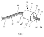
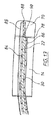
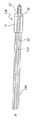
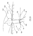
図1に示す管腔内陰圧補助閉鎖デバイス(endoVAC)は、実質的に円筒状の生体適合性スポンジ14の形態の多孔質要素を備え、スポンジ14は、患者の管腔内面と接触する外周面を備え、スポンジの近位端部18からその反対側の遠位端部20まで延在する、数字16で示す中心貫通通路を有している。スポンジの貫通通路内に、生理学的に許容可能なプラスチック材料から製作された排出チューブ22が受け入れられている。排出チューブは、さらに後述するように、使用時に体内物質がスポンジを通り患者の管腔から排出されるのを可能にする。
The endoluminal negative pressure assist closure device (endoVAC) shown in FIG. 1 comprises a porous element in the form of a substantially cylindrical
図示するように、排出チューブは、スポンジ14の近位端部から突出し、体内物質がチューブに入るための開放端部24で終端している。スポンジの前方のチューブの側壁に、体内物質が排出チューブの内部に入るためのさらなる開口部26が設けられている。同様に図1に示すように、排出チューブ22は、スポンジの遠位端部20から延在し、患者の体内から延出するのに十分な長さである。体内物質がスポンジの後方でチューブの内部に入るために、チューブの側壁にさらなる開口部28が設けられている。排出チューブ22のスポンジ内の部分は穿孔されておらず、それにより、排出チューブの内部は周囲のスポンジから封止されている。デバイス10が管腔内の適所に挿入されている間、スポンジを適所に保持するように、スポンジはその長さに沿って排出チューブに固定されている。スポンジを、たとえば好適な接着剤、または音波溶接あるいは熱溶接を用いることによってチューブに固定することができる。
As shown, the drain tube protrudes from the proximal end of the
患者の体外に配置された吸引源に接続される吸引チューブ30が、スポンジ14に陰圧をかけるためにスポンジ14と流体連通している。スポンジの近位端部18および遠位端部20はともに、気体および流体に対して本質的に不浸透性であるため、吸引チューブを介してスポンジにかけられる吸引力の作用により体内物質がスポンジ内に出て行かないように適合されている。
A
スポンジの近位端部および遠位端部を体内物質が入らないように封止するために、可撓性プラスチックシート材料のリングの形態の閉塞障壁を、適切な接着剤、熱溶接あるいは音波溶接または他の方法による等、あらゆる好適な方法で、それぞれの端部に取り付けることができる。この実施形態では、吸引チューブは、スポンジの遠位端部に取り付けられたプラスチックシートのリングに設けられた開口部内に封止して受け入れられるか、またはその開口部の周囲で終端し、それにより、吸引チューブの内部がスポンジと流体連通している。別法として、スポンジに、好適なプラスチック材料(たとえば、独立気泡フォーム)から形成された可撓性環状エンドキャップを設けることができ、エンドキャップは、吸引チューブを封止して受け入れ、吸引チューブを介してスポンジに吸引力をかけるようにスポンジの遠位端部に取り付けられている。こうした実施形態では、吸引チューブは、環状キャップの下側に画定された円周方向開放チャネル内に通じることができ、開放チャネルは、スポンジに対するかけられた吸引力のより均一な円周方向分布のために、スポンジの遠位端部に面している。しかしながら、好ましくは、他の形態では、吸引チューブ30は、スポンジ自体の中に延在し、吸引チューブのスポンジ内の部分の側壁に貫通開口部を有している。さらなる実施形態では、スポンジの近位端部および遠位端部を封止するために、この目的でシートプラスチック材料またはエンド/キャップを採用するのではなく、スポンジのそれぞれの端部に本質的に不浸透性のコーティングを塗布することができるが、あらゆる好適な方法または手段を利用することができる。
To seal the proximal and distal ends of the sponge from the entry of bodily substances, an occlusion barrier in the form of a ring of flexible plastic sheet material is used with a suitable adhesive, heat welding or sonic welding. Or it can be attached to each end in any suitable manner, such as by other methods. In this embodiment, the suction tube is sealed and received within an opening provided in a ring of plastic sheet attached to the distal end of the sponge, or terminates around the opening, thereby The interior of the suction tube is in fluid communication with the sponge. Alternatively, the sponge can be provided with a flexible annular end cap formed from a suitable plastic material (eg, closed cell foam), the end cap sealingly receiving the suction tube and receiving the suction tube And attached to the distal end of the sponge so as to apply a suction force to the sponge. In such embodiments, the suction tube can lead into a circumferential open channel defined on the underside of the annular cap, the open channel having a more uniform circumferential distribution of applied suction force against the sponge. In order to face the distal end of the sponge. Preferably, however, in another form, the
上述したような気体、糞便および/または体液がスポンジ14内に出て行かないようにスポンジ14の近位端部および/または遠位端部に閉塞障壁を設けることにより、スポンジ14の細菌の付着および「目詰まり」を最小限にすることができる。
By providing an obstruction barrier at the proximal and / or distal end of the
排出チューブの内部は、チューブの側壁によって貫通通路内でチューブの全長に沿ってスポンジから分離されている。すなわち、スポンジ14の近位端部と遠位端部との間で排出チューブの側壁に貫通開口部がなく、スポンジの外周面に吸引力がかけられることが確実になる。
The interior of the discharge tube is separated from the sponge along the entire length of the tube within the through passage by the side wall of the tube. That is, there is no through opening in the side wall of the discharge tube between the proximal end portion and the distal end portion of the
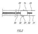
図2を参照すると、スポンジの外周面32は、スポンジの細孔を通して吸引チューブと流体連通しており、使用中にデバイス10が配置される管腔33を画定する周囲の管腔内面31の創傷部29に対して押圧される。適所に配置されると、外部吸引源からの吸引力がスポンジ14の外面を介して創傷部および周囲の管腔内面にかけられる。これにより、創傷部の周囲に局所陰圧領域が生成され、吸引力により、存在する可能性がある表面流体およびあらゆる滲出物が創傷部から離れてスポンジ内に引き込まれる。
Referring to FIG. 2, the outer
したがって、スポンジに吸引力を提供することに加えて、吸引チューブ30は、創傷部からスポンジを通して引き出される流体に対する第2排出チューブとして作用する。さらに、管腔内に存在する体内物質を、貫通通路16を介してスポンジを通して迂回させ、それにより、それら物質を創傷部からスポンジ内に引き込まれた流体から分離することにより、管腔内の体内物質によるスポンジの目詰まりおよび/または汚染、ならびに吸引チューブを介して創傷部に加えられる吸引力の関連する損失もまた、低減しまたは回避することができる。
Thus, in addition to providing suction to the sponge, the
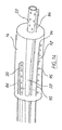
図1に示すものに類似しているが、スポンジの貫通通路16内、より詳細には排出チューブ22とスポンジ14との間に配置された拡張可能要素34を有する、endoVACデバイスもまた明示的に提供され、そこでは、拡張可能要素は、スポンジを拡張させてスポンジの外周面32を管腔内面と堅く接触するように押圧するように構成されている。
An endoVAC device similar to that shown in FIG. 1 but also having an
拡張可能要素はさまざまな形態をとることができる。たとえば、図3に示す実施形態では、拡張可能要素34は、弾性材料(たとえば、発泡プラスチック材料)から製作された管状インサートの形態であり、それは、デバイス10が、治療される創傷部に隣接した管腔に対して適所に位置している間に、周囲のスポンジ14が受け入れられる中空位置決めチューブ/シース(図示せず)によって排出チューブの周囲に圧縮状態で維持される。弾性材料は、通常拡張した静止状態に付勢されており、デバイスが管腔内に位置決めされ、挿入チューブまたはシースがスポンジから引き抜かれると、その状態に拡張してスポンジを創傷部および周囲の管腔内面に対して押圧する。
The expandable element can take a variety of forms. For example, in the embodiment shown in FIG. 3, the
別の形態では、位置決めチューブを使用する必要なしに、吸引力/陰圧を弾性インサートにかけてインサートを圧縮するさらなる吸引チューブを設けることができる。この実施形態では、スポンジに面している弾性インサートの外周面は、スポンジから(たとえば、不浸透性コーティングによって)封止されている。スポンジ14と同様に、インサートの近位端部および遠位端部もまた、たとえば、図1に関連して記載したような不浸透性コーティングまたは障壁のいずれかによって封止されている。したがって、さらなる吸引チューブを介して弾性インサートにかけられる陰圧を停止することにより、インサートがその通常の静止状態に拡張し、スポンジの外周面を管腔内面に対して押圧することができる。
In another form, an additional suction tube can be provided that compresses the insert by applying suction / negative pressure to the elastic insert without the need to use a positioning tube. In this embodiment, the outer peripheral surface of the elastic insert facing the sponge is sealed from the sponge (eg, by an impermeable coating). Like the
さらなる代替形態として、拡張可能要素34は、管状バルーン等の膨張式インサートの形態をとることができ、管状バルーンは、図4に概略的に示すように、スポンジの外周面を拡張させて管腔内面と押圧接触させるようにバルーンを膨張させる膨張チューブを備えている(膨張チューブは図示せず)。膨張チューブを、所定の圧力までバルーンを膨張させるように、患者の体外の手動式ポンプに接続することができる。過膨張を回避するために、ポンプに、圧力安全弁、および/または他の形態では、バルーンにかけられる圧力を示す圧力計が設けられている。好適に膨張すると、ポンプの弁が閉鎖されてバルーンは膨張状態で保持される。
As a further alternative, the
上述したことから、本明細書で用いる「拡張可能要素」という用語は、使用時に圧縮状態、つぶれた状態または収縮状態から拡張してスポンジ14の外周面を管腔内面に対して押圧することができる要素を包含することが理解されよう。したがって、拡張可能要素は、通常、拡張状態で存在することができる。さらに、(上述したような位置決めチューブまたはシースを用いても用いなくても)スポンジをつぶすかまたは圧縮させることは、管腔内面との摩擦接触を最小限にすることにより、デバイスが関連する体腔に沿って適所まで進むのに役立つことができることが理解されよう。
As described above, the term “expandable element” used in the present specification can be expanded from a compressed state, a collapsed state, or a contracted state to press the outer peripheral surface of the
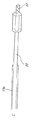
排出チューブ22を設けることが望ましいが、それは必須ではなく、本明細書に記載するようなendoVACデバイスの実施形態を、図5に示すように排出チューブなしで提供することができる。この実施形態では、管腔内に存在する体内物質は、デバイスが適所に配置されると、デバイス36の貫通通路16を単に通過することができる。
Although it is desirable to provide a
排出チューブが設けられている場合、排出チューブを、関連する体内物質を、デバイス10、36を通して引き出すようにプログラム可能なポンプまたは他の電動吸引ポンプに接続して、モニタリングおよび/または後の廃棄のために患者の体内からの物質を排出し衛生的に収集するのを促進することができる。吸引チューブ30に接続された外部吸引源は、同じかまたは別の電動ポンプであり得るが、必要な場合は、排出チューブ22および吸引チューブ30に吸引力/陰圧を提供するために、あらゆる好適な吸引源を利用することができる。上述したような吸引圧縮可能弾性インサート34が設けられるendoVACデバイスの実施形態では、そのインサートを、スポンジ14と同じかまたは異なる吸引源に接続することができる。
If a drain tube is provided, connect the drain tube to a pump or other motorized suction pump that can be programmed to draw the relevant body material through the
本明細書に記載するendoVACデバイスは、特に、結腸直腸癌(CRC)患者において癌組織を除去し明確な組織境界を提供する消化(GI)管の大腸の外科手術に続く、吻合部創傷の処置に適用される。外科手術の前(たとえば、24時間前)、ジプロピレングリコールおよび/または浣腸剤等の緩下剤を投与することによって、患者の腸から便を除去する。たとえば、盲腸または上行結腸の癌の場合、右半結腸切除術が行われる可能性があり、横行結腸癌の場合、拡大半結腸切除術が行われる可能性がある。下行結腸またはS状結腸の癌の患者では、外科手術は、典型的には、左半結腸切除術またはS状結腸切除術を含む。これらの外科手術の各々において、切除組織を接合することによって吻合部創傷が形成され、それを本発明によって処置することができる。 The endoVAC device described herein specifically treats an anastomotic wound following colonic surgery of the digestive (GI) tract that removes cancerous tissue and provides a clear tissue boundary in colorectal cancer (CRC) patients. Applies to Prior to surgery (eg, 24 hours prior), feces are removed from the patient's intestine by administering laxatives such as dipropylene glycol and / or enema. For example, for cecum or ascending colon cancer, a right hemicolectomy may be performed, and for transverse colon cancer, an expanded hemicolectomy may be performed. In patients with cancer of the descending colon or sigmoid colon, surgery typically includes left hemicolectomy or sigmoid colectomy. In each of these surgical procedures, an anastomotic wound is formed by joining the resected tissue and can be treated according to the present invention.
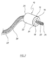
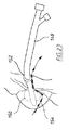
本明細書に記載するようなendoVACデバイスを、図6に概略的に示すように、たとえば腸と皮膚との間のろう孔の治癒を促進するために使用することも可能である。この実施形態では、デバイス38は、周囲のスポンジ14を、ろう孔64が通じている大腸管腔66の管腔内面と接触するように押圧する拡張可能要素34を有するタイプである。しかしながら、吸引チューブ30は、スポンジの遠位端部に吸引力をかけるかまたは他の方法でスポンジの遠位端部に入るのではなく、この場合、スポンジの側面からデバイス38に入り、ろう孔を通って対象の体内から突出する。吸引チューブは、たとえば、スポンジ内で分岐して、吸引チューブの一方の分岐がスポンジの中間からスポンジ内に沿って遠位方向に延在し、他方の分岐が反対方向にスポンジ内に沿って延在して、かけられる吸引力をスポンジの長さに沿って分散させるようにすることができる。endoVACデバイス38を、ろう孔を通して腸内の適所に挿入し、治癒を促進するようにろう孔の周囲の管腔内面に吸引力をかけることができる。ろう孔の治癒が進み、腸内へのろう孔の開口部を形成する組織が再構築されると、先のデバイスをろう孔から取り除きより小さいデバイスを同様に再挿入することによって、デバイス38をよりサイズの小さい別のデバイス38と交換することができる。ろう孔のサイズに応じて、これを1回または複数回繰り返すことができる。
An endoVAC device as described herein can also be used, for example, to promote healing of the fistula between the intestine and the skin, as shown schematically in FIG. In this embodiment, the
別の実施形態では、endoVACデバイス68を、ろう孔64の開口部を覆うように大腸内の適所に配置することができるが、吸引チューブ30は、図7に示すように、ろう孔から進んで外科的に形成された開口部から腸に入る。
In another embodiment, the
図8に、たとえば、切除された膵臓が、十二指腸と空腸として知られる回腸(iluem)との間の小腸の中間領域に外科的に縫合される膵空腸吻合術における治癒に使用されるのに好適なendoVACデバイス42を示す。このデバイスでは、スポンジ14は漏斗形であり、排出チューブ22および吸引チューブ30はスポンジの遠位面44から入り、スポンジの遠位面44は、その部分以外は、上述したように、気体および流体がスポンジ内に出て行かないように封止されている。図示するように、吸引チューブ30のスポンジ内の部分には、その側壁に沿って複数の貫通開口部が設けられており、スポンジの外径は、概して、スポンジの遠位から近位方向に低減して、シャフト48の形態でスポンジの突出部を形成し、そこから排出チューブ22が延出している。スポンジのシャフト48を、膵空腸吻合術では膵管の切除端に、または他の外科処置では管の切除端に挿入して、治癒プロセスを促進することができる。膵管は、膵液を膵臓から小腸に輸送する。膵液は、アルカリ性であり、脂肪を分解するように作用する酵素を含み、そのため、小腸の外部に著しい損傷をもたらす可能性がある。膵空腸吻合術の場合の「漏出率」は約15%程度である。
In FIG. 8, for example, the excised pancreas is suitable for use in healing in a pancreaticojejunostomy where it is surgically sutured to the middle region of the small intestine between the duodenum and the ileum known as the jejunum
図9に、膵空腸吻合技法の例を示し、そこでは、全体として数字54で示す膵臓の切除端52における膵管50の露出した開口部が、縫合糸56によって空腸の粘膜に縫合され、それにより、膵管が、空腸に外科的に形成された開口部を通して空腸58に通じている。図示する実施形態では、endoVACデバイス42は、空腸の管腔内に位置し、スポンジ14の突出したシャフト48は、膵管50の開放端に挿入されている。吸引チューブ30を介してスポンジにかけられる吸引力は、膵管の切除端の治癒を促進するだけでなく、空腸の粘膜に対する縫合創傷の治癒も促進するのに役立つことができる。膵管に隣接する空腸の側壁は、スポンジの漏斗形状に近接するようにも考えられ、吸引チューブによってスポンジにかけられる吸引力は、空腸の側壁をスポンジに対して保持しかつスポンジのシャフト48を膵管内の適所で保持するのに役立つ。すなわち、スポンジの外周面と少なくともスポンジの周囲の空腸の管腔内面とが、かけられる吸引力の影響で変形して、両方向矢印によって示すように互いに密着する。
FIG. 9 illustrates an example of a pancreatic jejunal anastomosis technique in which the exposed opening of the
いくつかの実施形態では、シャフトを通って長手方向に延在する、排出チューブ22の少なくともスポンジ内の部分は、拡張可能スリーブまたは好適なプラスチック材料の層によって、周囲のスポンジの貫通通路から封止された拡張可能ステントを備えることができる。別法として、たとえば、ステントが受け入れられるスポンジの貫通通路を、他の何らかの方法でステントから封止することができる。図8および図9に示すように、スポンジのシャフト48は、遠位から近位方向に先細りになっている。しかしながら、他の実施形態では、スポンジのシャフト48の直径は本質的に一定であり得る。さらに、シャフト48の近位端部を、体液がスポンジ内に出て行かないように封止することができるが、これはこのタイプのすべての実施形態において必須ではなく、それは、シャフト48の露出した近位端部は、膵管または他の管内の適所にありその管の周囲の管腔内面に対して押圧された時、典型的には最小厚さとなるためである。
In some embodiments, at least the portion within the sponge of the
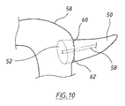
図10に、さらなる膵空腸吻合技法を示し、そこでは、膵臓の切除端部分全体が、空腸58の側壁に形成された開口部60内に挿入され、それにより、その側壁の開口部が縫合糸62によって膵臓に縫合されている。endoVACデバイス42のシャフト48は、この場合もまた、膵管58の切除開口部内に挿入され、膵管および膵臓の切除面52の治癒とともに、膵臓および空腸に対する縫合創傷の治癒を促進する。図9に示す実施形態と同様に、吸引チューブ30を介してスポンジにかけられた吸引力の作用により、スポンジ14の漏斗形本体が空腸の管腔内面および膵臓54の切除面と接触することが、スポンジを適所に保持するのにさらに役立つ。
FIG. 10 shows a further pancreatic jejunostomy technique in which the entire resected end portion of the pancreas is inserted into an
少なくともいくつかの実施形態では、本明細書に記載するようなendoVACデバイスに、関連する管腔33内の体内物質を収集しスポンジ14から排出チューブ22を介して排出するために、スポンジ14の近位(前方)および/または遠位(後方)に配置された別のそれぞれの多孔質要素を設けることができ、それにより、スポンジ14が閉塞するかまたは閉鎖するリスクを低減することができる。こうした追加の多孔質要素を設けることは、図1〜図7に示す実施形態において特に好適であるが、図8に示すようなendoVACデバイスに、そのデバイスのスポンジ24の前方および/または後方に配置された追加の多孔質要素を設け、追加の多孔質要素が、上述したような流体不浸透性障壁または他の手段等のそれぞれの閉塞障壁によってスポンジから封止されるかまたは分離されることもまた、明示的に包含される。
In at least some embodiments, an endoVAC device, as described herein, can be used in the vicinity of the
図11は、スポンジ14のほかに別の吸収要素が設けられている本発明のendoVacデバイス74の実施形態を示す。図示するように、さらなる吸収要素もまた、吸引チューブ30を介して吸引力がかけられるスポンジ14(すなわち、「VACスポンジ」)の前方に位置するスポンジ70の形態である。排出チューブ22は、「近位」スポンジ70を貫通し、そのスポンジの端面72に通じている。近位スポンジ70は、吸収性であり、そのため、排出チューブ22内に入るように体液および物質のその端面72および外周側面76内への吸収を促進するが、VACスポンジ14の封止端部に接合されて数字78で示す接合部を形成している。接合部/VACスポンジの封止された近位端面78は、近位スポンジ70に入る体内物質がVACスポンジ14内に入るのを阻止し、それら物質が排出チューブ22内に入り排出チューブを介してVACスポンジから排出されるようにする。それにより、近位スポンジは、VACスポンジの封止された近位端部78の周囲で体内物質が「漏出する」リスクまたは発生率、そのため、VACスポンジ14の付着または閉鎖の可能性を低減することができる。
FIG. 11 shows an embodiment of the
図12に、VACスポンジ14の前方および後方に配置された吸収スポンジの形態のそれぞれの多孔質要素が設けられている、本発明によって具現化されたendoVACデバイス94を示す。この実施形態では、排出チューブ22は、近位スポンジ70および「遠位」スポンジ80両方を貫通して、体液および他の体内物質が開口部26および28を介して排出チューブ内に入るようにする。図示するように、体内物質が遠位スポンジからVACスポンジ14内に入らないように、遠位スポンジの前端部はVACスポンジ14の封止された遠位端部に接合されて、数字82によって示す接合部を形成している。図11に示す実施形態と同様に、排出チューブ22の内部は、VACスポンジ内に通じておらず、吸引チューブ30は、近位スポンジ70または遠位スポンジ80のいずれにも通じていない。図11および図12における番号のない矢印は創傷を示す。スポンジ14と近位スポンジ70および/または遠位スポンジ80との間の接合部(たとえば82)を、スポンジ14と近位スポンジ70および/または遠位スポンジ80とを合わせて接合する閉塞接着剤によって形成することができる。別法として、接合部のそれぞれを、たとえば好適なプラスチック材料のシートによって提供することができ、そのシートに、スポンジのそれぞれの端部が取り付けられ、シートは、体内物質に対する不浸透性障壁を提供するが、他のあらゆる適切な方法を利用することができる。
FIG. 12 shows an
本発明の別の実施形態によれば、図13に示すように、吸引チューブ30が排出チューブ22を本質的に同心であるように受け入れる、図1〜図12のうちのいずれか1つに示すような本明細書に記載するようなendoVACデバイスを提供することができる。図13に示すように、吸引チューブ30の前端は、VACスポンジ14の近位端部において排出チューブ22の周囲で封止して終端し、排出チューブ22の外周は、概して、吸引チューブ30の内周から間隔が開けられ、排出チューブの周囲に吸引チューブの内腔84を画定している。図示しないが、排出チューブの遠位端領域は、上述したように、吸引チューブを通して、排出チューブチューブを収集容器および/または吸引チューブに接続する外部ポートまで封止して進むことができる。同様に、吸引チューブ30の遠位端部は、同じかまたは異なる吸引源に接続されるように適合された外部ポートに通じることができる。吸引チューブ30内に排出チューブ22を設けることにより、VACスポンジ14に吸引力をかけるためにendoVACデバイスの長手方向軸に沿って吸引チューブを最適に位置決めすることができ、かつ、VACスポンジに吸引力をかけるために吸引チューブの外周を最大化することができる。
According to another embodiment of the present invention, as shown in FIG. 13, the
また図13に示すように、本明細書に記載するようなendoVACデバイスは、排出チューブ22、吸引チューブ30およびVACスポンジ12の少なくとも1つを生理学的に許容可能な洗浄流体で洗浄するように適合された1つまたは複数の洗浄流路を含むことができる。より詳細には、図示する実施形態では、第1洗浄流路を形成する洗浄導管85が排出チューブに沿って位置し、第2洗浄流路を画定するさらなる洗浄導管86が、吸引チューブ30に沿って位置している。使用時、導管85および86は、洗浄流体源に接続され、洗浄流体は、導管のそれぞれの開放端部88および90から排出チューブおよび吸引チューブ内に流れ込んでそれらを洗浄し、それにより、排出チューブおよび吸引チューブが閉鎖するリスクを低減することができる。
Also as shown in FIG. 13, an endoVAC device as described herein is adapted to clean at least one of
図14に、本発明によって具現化されたendoVACデバイスの別の実施形態を示す。この実施形態では、排出チューブ22および吸引チューブ30の洗浄用の洗浄導管85および86とともに、VACスポンジ14の洗浄用の洗浄流路を画定するさらなる洗浄導管92が設けられている。見ることができるように、洗浄導管92は、閉鎖近位端部94を有しているが、スポンジ内に洗浄流体を供給するようにVACスポンジの外周面に向かうように向けられた、VACスポンジ12の長さに実質的に沿う複数の間隔を空けて配置された出口ポート95が設けられている。図13および図14に示す「陰圧」チューブ洗浄導管86および「排出」チューブ洗浄導管85には、洗浄流体用の単一出口しか設けられていないが、これらの導管のうちの一方または両方に、それらに沿って洗浄流体用の複数の間隔を空けて配置された出口ポートも設けることができる実施形態も提供することができる。
FIG. 14 illustrates another embodiment of an endoVAC device embodied by the present invention. In this embodiment, along with cleaning
洗浄流体は、滅菌水または生理食塩水製剤等、創傷および/または体内組織の洗浄に従来用いられるあらゆる好適な流体とすることができ、典型的には、重力またはかけられる圧力の作用で(たとえば、ペリスタルティックポンプまたは他のポンプを用いて)適用可能であるように排出チューブ、吸引チューブおよび/またはVACスポンジ14内に滴下供給される。それぞれの洗浄導管(すなわち、85、86および92)を、同じ生理学的に許容可能な流体源から供給することができるが、洗浄導管の異なるものに異なるこうした洗浄流体を供給することができる、本発明によるendoVACデバイスの実施形態を提供することができる。
The irrigation fluid can be any suitable fluid conventionally used for cleaning wounds and / or body tissues, such as sterile water or saline formulations, and is typically under the action of gravity or applied pressure (eg, (Using a peristaltic pump or other pump), which is dispensed into the drain tube, suction tube and / or
本発明のさらに別の態様では、デバイスが患者の上気道、G.I管またはより一般的には消化管で使用されて、デバイスが適所にある間に患者(patinet)の栄養投与および/または水分補給を促進する場合等、可撓性栄養チューブを、本明細書に記載するendoVACデバイスの貫通通路16(および、したがって、存在する場合は排出チューブ30)に挿入することができる。図15に、図12のタイプのendoVACデバイスを利用する例を示し、そこでは、デバイス94は、胃96の下方の十二指腸97内に位置して、数字98によって示す十二指腸潰瘍の治癒に役立つ。概略的に示すように、排出チューブ22および吸引チューブ30は、患者の鼻孔100から入り、栄養チューブ102は、遠位スポンジ80およびVACスポンジ14を通って排出チューブを下って延在し、対象の幽門後栄養投与のために排出チューブおよび近位スポンジ70から突出する。この実施形態で利用する栄養チューブ102は、フォーリー(Foley)カテーテル型チューブであり、それには、排出チューブ22を下って栄養チューブを挿入するのに役立つおもり付き開放近位先端104と、おもり付き先端の後方に配置された膨張式バルーン106(膨張状態で示す)とが設けられている。栄養チューブには、2つの長手方向内腔が設けられている。より詳細には、「膨張」内腔が、バルーンの膨張または収縮のためにバルーン106内に通じ、その遠位端部において、バルーンを膨張状態で維持するように閉鎖されるかまたは後にバルーンが収縮する時に開放される弁に接続されている。他方の「栄養投与」内腔は、栄養および/または流体製剤をG.I管まで通すように、栄養チューブのおもり付き先端104から消化管の管腔内に通じる貫通通路である。栄養チューブ102の内腔は、互いに分割され、栄養チューブの反対側の遠位端部領域に設けられたそれぞれの外部ポートに通じている。
In yet another aspect of the invention, the device is a patient's upper respiratory tract, G.P. A flexible feeding tube is used herein, such as when used in the I tube or, more commonly, the gastrointestinal tract, to facilitate the feeding and / or hydration of a patient while the device is in place. Can be inserted into the through-passage 16 (and thus the
栄養および/または流体製剤を、「栄養投与内腔」用の外部ポートに装着されたシリンジ内に装填し、重力の作用により、またはシリンジのバレルに装着されたプランジャの操作により、患者のG.I管内に送り込むことができる。バルーン106は、膨張すると、それが配置されているG.I管の内腔を画定する周囲の管腔内壁に対して押圧する。これは、栄養チューブ102の近位/前端部を適所に保持するのに役立つだけでなく、投与された栄養および/または流体製剤のendoVACデバイスの近位スポンジ70に向かう望ましくない逆流を阻止または抑止する。バルーン106を、膨張内腔の外部ポートに装着された手動式「スクイーズ」ポンプ等によるバルーンカテーテルの膨張に従来用いられるような方法で膨張させることができる。概して、バルーンの膨張状態をモニタリングするように配置された圧力計および/またはバルーンが過膨張していないことを確実にする過膨張安全逃し弁もまた設けられている。
A nutritional and / or fluid formulation is loaded into a syringe attached to an external port for a “nutrition delivery lumen” and is applied to the patient's G.P. by the action of gravity or by manipulation of a plunger attached to the barrel of the syringe. Can be fed into the I tube. When the
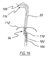
図16および図17に、図12に示す概略タイプの本発明によって具現化されたendoVacデバイスのさらなる実施形態をそれぞれ示す。特に、図16は、胃バイパス手術に続いてG.I管における漏出または吻合部110を処置するように、数字108によって示す胃ろう内に位置するendoVacデバイス94を示す。この場合もまた、バルーン106が近位端領域に配置された栄養チューブ102が、排出チューブ22を下って挿入され、上述したように患者の栄養投与および/または水分補給のために近位スポンジを越えて延出する。患者の横隔膜を数字112によって示し、患者の鼻孔および口をそれぞれ100および114によって示す。図17もまた、上述したようにendoVacデバイスと組み合わせた膨張式バルーン106を備えた栄養チューブを示す。ただしこの場合は、endoVacデバイス94は上部G.I管に位置し、VACスポンジ14は、食道切除(esophyectomy)に続く吻合部118の漏出部116に位置合せされている。
FIGS. 16 and 17 show further embodiments of an endoVac device embodied by the present invention of the general type shown in FIG. 12, respectively. In particular, FIG. Shown is an
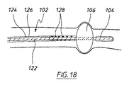
少なくともいくつかの実施形態では、近位端領域に膨張式バルーン106が設けられている栄養チューブ102は、図18に概略的に示すようにバルーンが膨張した時、バルーン106の遠位側に溜まるかまたは蓄積する可能性がある体液および他の体内物質を排出する、さらなる長手方向内腔を含むことができる。図示する実施形態では、「栄養投与」内腔は、内部長手方向導管122によって画定され、その周囲に、栄養チューブの外壁126によって「排出」内腔124が画定されている。体液および他の体内物質が排出内腔に入るのを可能にするために、バルーン106の後方の栄養チューブの外壁126に複数の貫通開口部128が設けられている。排出内腔124の遠位端部は、吸引源に接続するためのさらなる外部ポートにおいて終端して、体内物質が排出内腔から収集容器に排出されるのに役立つことができる。バルーンの膨張または収縮のための「膨張」内腔は図示していない。しかしながら、たとえば、排出内腔内に配置された長手方向に延在する導管によって、膨張内腔を設けることができる。
In at least some embodiments, the feeding
図19A〜図19Eに、本明細書に記載するようなendoVacデバイスの適所への配置を示す。より詳細には、図19Aに示すように、最初に、患者の関連する体腔内にガイドワイヤ130が挿入され、その後、オーバワイヤステント/ガイドチューブ132がガイドワイヤの上を摺動し、その後、ガイドワイヤが引き抜かれて、ガイドチューブ132が管腔内の適所に残される(図19B〜図19Cを参照)。そして、図19Dに示すように、endoVAcデバイス134がガイドチューブ132を下って摺動し、それにより、ガイドチューブがendoVACデバイスの排出チューブ22によって(またはより概略的には、デバイスの貫通通路16を通して)受け取られ、ガイドチューブ132はその後、引き抜かれ、それにより、endoVACデバイス134は患者の管腔内の適所に残される。
Figures 19A-19E illustrate the placement of an endoVac device as described herein in place. More specifically, as shown in FIG. 19A, first, a
たとえば肛門の大腸における等、endoVACデバイスを処置される創傷部に隣接する適所に配置するために、必要に応じて望ましくはわずかなまたは好適な湾曲を有する内視鏡型観察デバイス(たとえば、剛性または半可撓性のS状結腸鏡または結腸鏡)を採用することも可能である。この場合、たとえば図20A〜図20Cに示すように、endoVACデバイスを、内視鏡の端部に取り付け、かつ/または他の方法で、内視鏡が患者の体内に挿入される際に大腸の管腔に沿って移動させることができる。図示するように、プッシュオーバチューブ136およびendoVACデバイス138を内視鏡に予め装填することができ、それにより、内視鏡は、この場合もまた、endoVACデバイスの排出チューブ22(および/または貫通通路16)に挿入される。内視鏡を用いて、管腔に沿ってendoVACデバイス138が案内され、endoVACデバイスは、オーバチューブをVACスポンジ14(または設けられている場合は遠位スポンジ80)の遠位端部と当接した状態で維持することにより、内視鏡の適所に維持される。endoVACデバイス138が適所に置かれると、内視鏡は患者の体内から引き抜かれ、オーバチューブ136を用いてendoVACデバイスが適所に保持される。そして、患者の体内からオーバチューブ136が引き抜かれる。
In order to place the endoVAC device in place adjacent to the wound to be treated, such as in the anus large intestine, an endoscopic viewing device (eg rigid or It is also possible to employ a semi-flexible sigmoidoscope or colonoscope). In this case, for example, as shown in FIGS. 20A-20C, an endoVAC device may be attached to the end of the endoscope and / or otherwise removed from the large intestine as the endoscope is inserted into the patient's body. It can be moved along the lumen. As shown, the
しかしながら、上述したようにendoVACデバイスを体腔内で位置決めするために、あらゆる本質的に剛性の細長いイントロデューサを、単独で、または別の器具(たとえば、VACスポンジ14または遠位スポンジ80に対して押圧されるプッシュオーバチューブまたはスタイレット)とともに用いることができる。たとえば、イントロデューサは、endoVACデバイスの排出チューブ22/貫通通路16内にまたはそれを通して挿入されるように好適に寸法が決められた角度付きの近位端部を有する内部円形外科用ステープラ等の本質的に剛性のチューブの形態であり得る。
However, in order to position the endoVAC device in the body cavity as described above, any essentially rigid elongated introducer may be pressed alone or against another instrument (eg,
VACスポンジ14(および設けられている場合は隣接する近位スポンジ70および遠位スポンジ80)を、図3および図4に関連して上述したように、患者の体腔に沿って適所まで移動させるのを容易にするように、つぶれた状態または圧縮状態で保持することができる。これを、中空位置決めチューブまたはシースを用いて達成することができるが、別の実施形態では、スポンジをつぶれた状態または圧縮状態で保持するスポンジ(14、70、80)の外周面(たとえば32)の周囲に巻き付くカバー(たとえば、好適なプラスチック材料の熱収縮ラップまたは他のフィルム)を設けることができ、その場合、endoVACデバイスが適所に置かれると、カバーはスポンジから剥離されるかまたは引き抜かれ、それにより、スポンジが拡張して(または拡張させられて)周囲の管腔内面と押圧接触することができる。1つまたは複数の実施形態では、カバーは、スポンジからの取外しを容易にするように引き裂かれ折れやすい裂け線、および/または外側摩擦低減コーティング(たとえば、テフロン(登録商標)または生理学的に許容可能な潤滑剤)であって、コーティングと患者の管腔内面との間の摩擦を低減するコーティングを有することができる。
The VAC sponge 14 (and adjacent
この実施形態の例を、図21A〜図21Cに概略的に示し、それらの図は、オーバワイヤステントまたは他の好適なガイドチューブ132の上に装填された、本発明によるendoVACデバイス140を示し、そこでは、ガイドチューブは、デバイスの排出チューブ22内に挿入されている。図21Aに示すように、デバイスのVACスポンジ14は、VACスポンジの外周面32を包囲するプラスチックラップ142の形態のカバーと、吸引チューブ30を介してVACスポンジ14に(かつ/または、たとえば、さらなる吸引チューブによって上述したように弾性インサート等の形態の下にある拡張可能要素34に)かけられる陰圧とによって、対象の体腔内に位置するように圧縮状態で保持される。ラップ142がVACスポンジ14から引き抜かれる際、図21Bに示すように、スポンジの近位端領域は、その通常の拡張静止位置まで拡張し始める。図21Cに示すように、ラップ142が完全に取り除かれた時、VACスポンジは、その完全な通常の拡張状態になる。そして、ガイドチューブ132もまた引き抜くことができるが、いくつかの実施形態では、プラスチックラップ142を取り除く前に、ガイドチューブ132を引き抜くことができる。
An example of this embodiment is shown schematically in FIGS. 21A-21C, which show an
カバー142の取外しを容易にするために、カバー142を、対象の体内から外側に突出するのに十分な長さで提供することができ、それにより、endoVACデバイスがプッシュオーバチューブ(たとえば136)、スタイレット等によって適所に保持されている間に、カバー142を、手で把持し、スポンジ(適用可能性に応じて14、70、80)を露出させるように後方に引っ張ることができる。別法として、カバーを、内視鏡、またはendoVACデバイスを適所に配置するために使用される他のイントロデューサに(たとえば、クランプの接着テープにより)直接取り付けられるのに十分な長さとすることができ、それにより、内視鏡または他の位置決め装置が引き抜かれる時、カバーがスポンジから引き抜かれる。さらに別のオプションとして、カバーに取り付けられる専用ロッド、カテーテル等をendoVacデバイスとともに適所に挿入することができ、それにより、ロッド等の引抜により、カバーがスポンジから剥離されかつ/または引き抜かれる。周囲の管腔内面と押圧接触するように自己拡張するのではなく、膨張式拡張可能要素34(たとえばバルーン)が設けられたendoVACデバイスのスポンジを、同様に上述したようにバルーン34の膨張によって、管状内面と押圧接触するように拡張させることができる。
To facilitate removal of the
図22に、膨張式ブラダ34の形態の膨張式拡張可能要素が設けられた、対象の直腸内における、数字144によって示すろう孔、創傷部または漏出部を処置するendoVACデバイスの別の実施形態を示す。この実施形態では、排出チューブ22は、便および糞便の収集を促進するように漏斗状である。適所に配置されると、ブラダは、膨張チューブ(図示せず)を介して膨張して、VACスポンジ14を、直腸の管腔内面の創傷部144と押圧接触するように拡張させる。排出チューブ22の近位終端「漏斗状」リム146を完全に開放したまま維持するのに役立つために、リムを、排出チューブの膨張式環状コンパートメントによって形成することができる。膨張式コンパートメントは、ブラダと同時に膨張するようにブラダ34と流体連通することができ、または別個の膨張ラインを介して膨張可能であり得る。
FIG. 22 shows another embodiment of an endoVAC device for treating a fistula, wound or leak, indicated by
本明細書に記載するようなendoVACデバイスを上部G.I管または下部G.I管のような管腔内空間内に位置決めするのに役立つように、デバイスの位置を、別の外科医または看護師によって、超音波またはたとえば造影剤を採用するX線透視技法によってモニタリングすることができる。 The endoVAC device as described herein can be I tube or lower G. The position of the device may be monitored by another surgeon or nurse by ultrasound or fluoroscopic techniques employing, for example, contrast agents, to help position within an intraluminal space such as the I tube it can.
陰圧補助創傷療法に対するさらなる代替形態として、患者の管腔内でendoVACデバイスを使用して、デバイスが管腔に沿って位置し、スポンジ14が上述したように患者の体内に完全に取り込まれる代りに、本明細書に記載するような陰圧下でのスポンジまたは他の可撓性多孔質要素を、中心静脈カテーテルライン、留置ドレーン、栄養チューブ、または患者の皮膚を通して挿入される他のこうしたチューブの周囲における組織の陰圧補助治療に対して採用することができる。
As a further alternative to negative pressure assisted wound therapy, instead of using an endoVAC device within the patient's lumen, the device is positioned along the lumen and the
患者の皮膚の創傷部(たとえば、ろう孔または外科的に形成された開口部)を通して体内に入るドレーンおよび他のチューブは、創傷に対する持続的刺激源を提供する。これは、チューブと周囲の創傷部との間からの流体の漏出によって悪化する可能性があり、その結果、チューブ進入部位の周囲に、表皮剥離(exoriation)、腐食、およびより深刻な場合は慢性潰瘍をもたらす可能性がある。これは、特に、栄養チューブまたはドレーンが皮膚を通してG.I管内に挿入される場合であり、そこでは、G.I分泌物/流体(たとえば、酸、酵素、胆汁等)が、図23に示すようにチューブと創傷部との間の皮膚創傷部位を通して漏れる可能性があり、図23には、フォーリー型膨張式バルーン150が設けられかつ患者の皮膚の創傷152部を貫通する栄養チューブ148を示す。矢印154により、流体/分泌物が、膨張したバルーン150と管腔内粘膜との間を通り、筋膜組織を横切り栄養チューブ148と皮膚152との間から出る流れを示す。
Drains and other tubes that enter the body through wounds (eg, fistulas or surgically formed openings) in the patient's skin provide a continuous source of stimulation for the wound. This can be exacerbated by leakage of fluid from between the tube and the surrounding wound, resulting in exortion, corrosion, and more severe chronicity around the tube entry site. May cause ulcers. This is especially true when the feeding tube or drain is passed through the skin by G. In the I tube, where G. I secretions / fluids (eg, acids, enzymes, bile, etc.) may leak through the skin wound site between the tube and the wound as shown in FIG. Shown is a
したがって、本発明の別の態様では、患者の皮膚の創傷部に陰圧をかけるデバイスが提供され、デバイスは、創傷部内に挿入される挿入チューブと、創傷部に陰圧をかけるように創傷部内に挿入される可撓性多孔質要素と、患者の体外の吸引源に接続され、多孔質要素と流体連通して吸引源の作動により多孔質要素に陰圧をかける吸引チューブとを備え、多孔質要素は挿入チューブに取り付けられている。 Accordingly, in another aspect of the present invention, a device is provided for applying negative pressure to a wound in a patient's skin, the device being inserted into the wound and an insertion tube inserted into the wound and within the wound to apply negative pressure to the wound. Comprising a flexible porous element inserted into a suction source and a suction tube connected to a suction source outside the patient's body and in fluid communication with the porous element to apply a negative pressure to the porous element upon actuation of the suction source; The quality element is attached to the insertion tube.
上述した実施形態と同様に、多孔質要素は、吸収スポンジを含むことができる。典型的には、スポンジの反対側の近位端部および遠位端部で、それらのうちの少なくとも一方は、体内物質がスポンジ内に出て行かないように適合され(たとえば封止され)、それは最も典型的には少なくとも近位端である。 Similar to the embodiments described above, the porous element can include an absorbent sponge. Typically, at the opposite proximal and distal ends of the sponge, at least one of them is adapted (eg, sealed) to prevent bodily matter from exiting into the sponge, It is most typically at least the proximal end.
典型的には、挿入チューブはスポンジを貫通する。少なくともいくつかの実施形態では、概略的に上述したように、挿入チューブは、スポンジの貫通通路内に受け入れられる。しかしながら、少なくともいくつかの実施形態では、スポンジは、使用時に挿入チューブの周囲に巻き付けられるマットの形態であり得る。 Typically, the insertion tube penetrates the sponge. In at least some embodiments, as generally described above, the insertion tube is received within the through passage of the sponge. However, in at least some embodiments, the sponge may be in the form of a mat that is wrapped around the insertion tube in use.
典型的には、デバイスは、チューブの周囲に巻き付けられるとマットを巻付け状態で保持するようにマットを締結する締結システムをさらに含む。締結システムは、(たとえば、VelcroTM型の)「フックテープ」システムを含むことができるが、いかなる好適な締結システムも利用することができる。 Typically, the device further includes a fastening system that fastens the mat to hold the mat in a wrapped state when wrapped around the tube. The fastening system can include a “hook tape” system (eg, of the Velcro ™ type), although any suitable fastening system can be utilized.
本発明のこの態様によるデバイスの挿入チューブは、スポンジの近位方向前方に配置された膨張式バルーンも備えることができ、バルーンは、患者の管腔内の適所に挿入チューブを係留させるように膨張可能である。 The insertion tube of the device according to this aspect of the invention may also comprise an inflatable balloon disposed proximally forward of the sponge, the balloon inflated to anchor the insertion tube in place within the patient's lumen. Is possible.
図24に、本発明のこの態様の実施形態を概略的に示す。図示する陰圧スポンジデバイス156は、図16に関連して概して上述したように、フォーリーバルーン160(ここでは膨張状態で示す)を備えた標準型栄養チューブ158の形態の挿入チューブを備えている。VACスポンジ14が、皮膚の傷口に挿入されるためにバルーンの後方において栄養チューブ158の適所に設けられ、それにより、VACスポンジ14の周囲側面159は、周囲の創傷部に対して押圧される。スポンジ14は、栄養チューブが貫通する、数字160によって示す中心貫通通路と、吸引チューブ30とを有している。吸引チューブ30は、上述したendoVACデバイスの実施形態と同様にVACスポンジ内に通じ、VACスポンジ14の周囲側面159を介して創傷部に陰圧をかけるように、外部吸引源に接続する外部ポート162で終端している。少なくともいくつかの実施形態では、VACスポンジ14用の吸引チューブ30は、栄養チューブの一体(intergral)構成要素であり得る。他の実施形態では、VACスポンジおよびその吸引チューブ30を栄養チューブに取り付けることができる。
FIG. 24 schematically illustrates an embodiment of this aspect of the invention. The negative
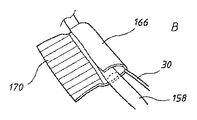
図25に、陰圧スポンジデバイス164の別の実施形態を示す。この場合、VACスポンジ14はマットの形態であり、マットの端縁166に吸引チューブ30が配置されている。使用時にマットに陰圧をかけるために、マット内の吸引チューブの領域に沿って複数の貫通開口部168が設けられている。VelcroTM型締結システムで使用される一般的なタイプのフックテープ170の形態の締結システムが、端縁166に対するマット14の反対側の端部領域172の「内」面に取り付けられている。対象の皮膚の創傷を通して挿入される栄養チューブ(たとえば158)または他の挿入チューブの適所にマットを取り付けるために、図25A〜図25Cに示すように、チューブはマットの端縁166に配置され、マットはチューブの周囲に密に巻き付けられている。マット14の締結は、フックテープをマットの反対側の「外」面の露出したスポンジ材料と係合させることによって達成される(図25Cを参照)。図26に、皮膚176を通して創傷部174内の適所にある陰圧スポンジデバイス164の例示を示し、そこでは、栄養チューブ158の近位端部は、筋膜組織178を通って腸180の管腔(たとえば胃)内に延在し、バルーン160は膨張状態にある。図25A〜図25Cおよび図26に示すタイプのデバイスが適所にある時、透明なまたは他の好適な接着テープまたはカバーが、栄養チューブ158(または他の挿入チューブ)の周囲で創傷部の上に配置されて、デバイスを適所に固定し、デバイスの吸引チューブ30を介してマットによって創傷部に吸引力をかけるように、巻かれたマット14の外端部を空気から封止する。
FIG. 25 illustrates another embodiment of a negative
少なくともいくつかの実施形態におけるVACスポンジ14/マットを、創傷部を通して挿入チューブを配置した後、創傷部内に関連する挿入チューブに沿って摺動させることができる。したがって、VACスポンジまたはマット14を、既存のあるいは事前に挿入されたドレーンまたは他の挿入チューブに後付けして、創傷部の治療のために創傷部の適所まで摺動させることができる。
The
本明細書に記載するように栄養チューブまたは他の挿入チューブが通って延在する皮膚の創傷部内における陰圧補助デバイス(たとえば、156、164)のVACスポンジ/マット14の位置は、本来、創傷部から漏出する可能性がある流体を管理すること、創傷組織を合わせて引き出すこと、創傷治癒プロセスを強化するかまたは速めること、既存の組織の表皮剥離または創傷組織の腐食の悪化を遅らせるかまたは回避すること、および創傷組織の浮腫を回避し、管理しまたは低減することのうちの1つまたは複数等、望ましい結果を提供することができる。
The position of the VAC sponge /
典型的には、吸引チューブ30を介して本発明によって具現化されたendoVACデバイスのスポンジ14にかけられる吸引力は、5.5mmHgを越え、概して、11mmHgから140mmHgまでの範囲となる。最も典型的には、スポンジ14にかけられる吸引力は50mmHg〜100mmHgの範囲であるが、異なる用途およびendoVACデバイスに対して異なるレベルの吸引力を利用することができ、最適な吸引力のレベルは、担当する医師または医療従事者が決めることができる。
Typically, the suction force applied to the
創傷が治癒する3日間から5日間、本明細書に記載したようなデバイスは、略適所に保持され、関連する創傷部に陰圧がかけられる。患者の皮膚を通る創傷部が処置される実施形態では、創傷部の陰圧治療はより長い期間続く可能性があり、その間、VACスポンジ14が1回または複数回交換される可能性がある。
During the 3 to 5 days that the wound heals, a device as described herein is held in approximately place and negative pressure is applied to the associated wound site. In embodiments in which the wound through the patient's skin is treated, the negative pressure treatment of the wound may last for a longer period, during which time the
大腸以外に、本発明によって具現化されたendoVACデバイスを、たとえば、食道切除術または肥満外科手術の後等、上述したようなろう孔、ならびに卵管、上部消化(G.I管)、気管、気管支、食道、食道胃、胃空腸および膵空腸の損傷の治癒に役立つように利用することができる。実際には、管腔内面は、本明細書に記載したようなデバイスでの処置に適するあらゆるG.I管または他の管腔内面であり得る。さらに、組織の切除からもたらされる創傷のほかに、本明細書に記載するようなデバイスは、限定されないが、潰瘍、外傷、放射線治療、高周波アブレーション、エタノール焼灼、凍結手術、化学療法およびポリペクトミーからもたらされる創傷の治癒の補助に適用される。そのため、本明細書で用いる「創傷」という用語は、その最も広い文脈で、外科手術および医療処置によって負わされた創傷、事故による外傷、ならびに生理的疾患または病状からもたらされる創傷(たとえば、ろう孔)を包含するように解釈されるべきである。 In addition to the large intestine, the endoVAC device embodied by the present invention can be used for fistula as described above, such as after esophagectomy or bariatric surgery, as well as the fallopian tube, upper digestion (GI tract), trachea, It can be used to help heal bronchial, esophageal, esophageal stomach, gastrojejunum and pancreatic jejunum damage. In practice, the luminal surface may be any G.M. suitable for treatment with a device as described herein. It can be an I tube or other luminal surface. In addition to wounds resulting from tissue resection, devices such as those described herein include, but are not limited to, ulcers, trauma, radiation therapy, radiofrequency ablation, ethanol ablation, cryosurgery, chemotherapy and polypectomy. Applied to assist wound healing. As such, the term “wound” as used herein, in its broadest context, refers to wounds caused by surgery and medical procedures, accidental trauma, and wounds resulting from physiological diseases or conditions (eg, fistulae). ).
本発明のデバイスで使用されるのに好適なさまざまなタイプのVACスポンジ14が既知でありその限定しない例としては、網状気泡構造があってもなくても、連続気泡ポリウレタンおよびポリビニルアルコール発泡プラスチックを挙げることができる。スポンジの細孔は、約100μMから約1000μMの範囲、より一般的には、約200μMから600μMの範囲、概して、約400μMから600μMの範囲であり得る。望ましくは、採用される発泡プラスチック材料は、本質的に、創傷部に接着しない。別法として、創傷部に対するいかなる有害な付着またはスポンジ14内への組織内部成長が発生する前に、デバイスを患者の体内から取り除くことができる。本発明によるデバイスの他の実施形態では、多孔質要素14および/またはさらなる吸収要素(たとえば、70および/または80)が形成される吸収材料は、(たとえば、従来創傷の治療に使用される)好適なガーゼまたは詰め物であり得る。
Various types of
本発明によって具現化されたendoVACデバイスを、容易に入手可能な材料を用いて提供することができる。たとえば、患者がブタ科の一種である場合、開孔スポンジの円筒状チューブを縦方向に切断し、管材(たとえば、フレンチサイズ16または18、Bard Medical,Convington、GA、USA)をスポンジ内の適所に縫合して、吸引チューブ30を提供することができる。そして、排出チューブ22を形成するさらなるこうした管材が、スポンジの近位端を越えて延在するようにスポンジ内に配置され、スポンジ内の適所に縫合されて吸引チューブに固定される。そして、スポンジは、両チューブの上で長手方向に閉鎖して縫合されてそれらを内部に封入し、不浸透性テープがスポンジの周囲に巻き付けられて、スポンジの露出した近位端部および遠位端部を封止する。本発明のデバイスの実施形態のスポンジ14および/あるいはさらなる吸収要素70ならびに/または80として使用されるのに好適な発泡プラスチック材料は、市販されている(たとえば、GranuFoamTMスポンジ、Kinetic Concepts,Inc.、San Antonio、TX、USA)。
The endoVAC device embodied by the present invention can be provided using readily available materials. For example, if the patient is a porcine family, a cylindrical tube of open-pore sponge is cut longitudinally and tubing (eg
本発明によるデバイスを採用することにより、1つまたは複数の実施形態では、CRC等に対する大腸の外科手術に関連するコロストミーまたはイレオストミー(たとえば、低位前方切除術(LAR))と、コロストミーまたはイレオストミーの後の元に戻す手術に関連する吻合部漏出のリスクとを回避することができる。同様に、吻合部創傷の治癒を容易にすることにより、漏出および/または創傷部の感染のリスクを低減することができる。治癒をさらに促進するために、少なくともいくつかの実施形態では、VACスポンジまたは他の多孔質要素14を、創傷部位で放出されるかまたは創傷部位に適用される抗生物質等の薬物または他の治療薬を含浸させるかまたはコーティングすることができる。たとえば、創傷部に適用するために、スポンジの外周面に、銀イオン放出抗菌性コーティングを塗布することができる。
By employing a device according to the present invention, in one or more embodiments, a colostomy or ileostomy associated with colorectal surgery for CRC or the like (eg, low anterior resection (LAR)) and after colostomy or ileostomy The risk of anastomotic leakage associated with undoing surgery can be avoided. Similarly, facilitating healing of an anastomotic wound can reduce the risk of leakage and / or infection of the wound. To further promote healing, in at least some embodiments, the VAC sponge or other
さまざまな実施形態を上述したが、本発明から逸脱することなく多数のさまざまな変更を行うことができることが理解されよう。たとえば、拡張可能要素34がステント(たとえば、ワイヤまたは他の好適なステント)であり、そのステントが、デバイスが患者の体内の適所に位置している時はつぶれた状態であり、使用時、拡張して外側スポンジ14を創傷部および周囲の管腔内面と接触するように押圧するように動作可能に配置されている、実施形態を提供することができる。ステントは、通常、ステントをスポンジから封止する拡張可能プラスチックまたは他のカバー内に封入される。あらゆる好適なこうしたステントを採用することができる。さらに、排出チューブ22の内径を、以下の添付図面に示す特定の実施形態のものより大きくすることができ、したがって、本発明によって具現化されたendoVACデバイスの相対的な寸法および比率は変更することができ、現時点で例示されている実施形態のものに限定されない。
While various embodiments have been described above, it will be appreciated that many different modifications can be made without departing from the invention. For example, the
したがって、上述した実施形態は、単に例示するものであって限定するものではない。
本発明は、特許請求の範囲に記載されるものの他、以下の態様を含む。
1. 患者の体内の管腔内面の創傷部を処置する方法であって、
前記創傷部に陰圧をかけるデバイスを提供するステップであって、前記デバイスが、前記創傷部と接触する外周面を備える可撓性多孔質要素であって、前記外周面が前記多孔質要素の反対側の近位端部と遠位端部との間に画定される、多孔質要素と、前記管腔内面によって形成された体腔内の体内物質を吸収し、前記多孔質要素の前方または後方に配置される少なくとも1つの吸収要素であって、前記多孔質要素と前記吸収要素との間にそれぞれの接合部が画定される、吸収要素と、前記患者の体外の吸引源に接続され、前記多孔質要素と流体連通して、前記吸引源の作動時に前記多孔質要素の前記外周面を介して前記創傷部に陰圧をかける吸引チューブとを有する、ステップと、
前記管腔内面によって形成された前記管腔内の適所に前記デバイスを配置するステップと、
前記多孔質要素の前記外周面を介して前記創傷部に陰圧をかけるステップであって、前記多孔質要素の少なくとも1つの長手方向に延在する貫通通路が、前記管腔からの前記体内物質が前記デバイスを通過するように、前記多孔質要素と前記吸収要素との間の前記接合部を通って前記吸収要素内に延在し、前記接合部が、前記貫通通路を除き、前記多孔質要素と前記吸収要素との間で前記体内物質が出て行かないように適合される、ステップと、
を含む方法。
2. 前記貫通通路が、完全にそれぞれの前記吸収要素を通って延在する、上記1.に記載の方法。
3. 前記吸収要素が、前記多孔質要素の前記近位端部または前記遠位端部に接合される、上記2.に記載の方法。
4. 前記デバイスが、前記多孔質要素の前方に配置された前記吸収要素を備える、上記1.〜3.のいずれか一つに記載の方法。
5. 前記デバイスが、前記多孔質要素の後方に配置された前記吸収要素を備える、上記1.〜4.のいずれか一つに記載の方法。
6. 前記デバイスが排出チューブをさらに備え、前記排出チューブが、前記体内物質が前記排出チューブに沿って対象の外部に出るように前記多孔質要素の前記貫通通路内に受け入れられる、上記1.〜5.のいずれか一つに記載の方法。
7. 前記多孔質要素が吸収材料から製作される、上記1.〜6.のいずれか一つに記載の方法。
8. 前記多孔質要素および前記少なくとも1つの吸収要素が、各々、それぞれのスポンジである、上記1.〜7.のいずれか一つに記載の方法。
9. 患者の体内の管腔内面に陰圧をかけて前記管腔内面の創傷部を処置するデバイスであって、
前記創傷部と接触する外周面を備えた可撓性多孔質要素であって、前記外周面が前記多孔質要素の反対側の近位端部と遠位端部との間に画定されており、前記多孔質要素が、前記管腔内面によって画定された管腔からの体内物質が前記多孔質要素を通過するように、その前記近位端部からその遠位端部まで延在する少なくとも1つの貫通通路を有する、多孔質要素と、
前記患者の体外の吸引源に接続され、前記多孔質要素と流体連通して、前記吸引源の作動時に前記多孔質要素の前記外周面を介して前記創傷部に陰圧をかける吸引チューブと、
前記多孔質要素内にまたはそれを通して洗浄流体を送達する少なくとも1つの洗浄流路と、
を具備するデバイス。
10. 前記洗浄流体を前記吸引チューブに送達する前記洗浄流路を具備する、上記9.に記載のデバイス。
11. 前記洗浄流体を前記多孔質要素の前記外周面に隣接する前記多孔質要素の外周領域に送達する前記洗浄流路を具備する、上記9.または10.に記載のデバイス。
12. 前記体内物質を収集し排出する排出チューブであって、前記多孔質要素の前記貫通通路内に配置されている排出チューブと、
前記排出チューブ内に前記洗浄流体を送達する前記洗浄流路であって、前記洗浄流体を前記排出チューブに供給する洗浄導管によって画定されている洗浄流路と、
をさらに具備する、上記9.〜11.のいずれか一つに記載のデバイス。
13. 前記多孔質要素が吸収材料から製作されている、上記9.〜12.のいずれか一つに記載のデバイス。
14. 前記多孔質要素がスポンジである、上記13.に記載のデバイス。
15. 患者の体内の管腔内面の創傷部を処置する方法であって、
前記創傷部に陰圧をかけるデバイスを提供するステップであって、前記デバイスが、前記創傷部と接触する外周面を備えた可撓性多孔質要素であって、前記デバイスの前記外周面が前記多孔質要素の反対側の近位端部と遠位端部との間に画定される、多孔質要素と、前記患者の体外の吸引源に接続され、前記多孔質要素と流体連通して、前記吸引源の作動時に前記多孔質要素の前記外周面を介して前記創傷部に陰圧をかける吸引チューブと、前記多孔質要素内にまたはそれを通して洗浄流体を送達する少なくとも1つの洗浄流路とを備える、ステップと、
前記管腔内面によって形成された前記管腔内の適所に前記デバイスを配置するステップと、
前記多孔質要素の前記外周面を介して前記創傷部に陰圧をかけるステップであって、前記多孔質要素が、管腔からの体内物質が前記多孔質要素を通過するように、その近位端部からその遠位端部まで延在する少なくとも1つの貫通通路を有する、ステップと
前記洗浄流路を通して前記多孔質要素に洗浄流体を供給するステップと、
を含む方法。
16. 前記洗浄流体を前記吸引チューブに送達するように前記洗浄流路を通して前記洗浄流体を供給するステップを含む、上記15.に記載の方法。
17. 前記洗浄流体を、前記多孔質要素の前記外周面に隣接する前記多孔質要素の外周領域に送達するように前記洗浄流路を通して前記洗浄流体を供給するステップを含む、上記15.または16.に記載のデバイス。
18. 前記デバイスが、前記体内物質を収集し排出する排出チューブをさらに有し、前記排出チューブが、前記多孔質要素の前記貫通通路内に配置され、前記方法が、前記洗浄流体を前記排出チューブ内に送達するように前記洗浄流路を通して前記洗浄流体を供給するステップを含む、上記15.〜17.のいずれか一つに記載のデバイス。
19. 前記多孔質要素が吸収材料から製作される、上記15.〜18.のいずれか一つに記載のデバイス。
20. 前記多孔質要素がスポンジである、上記19.に記載のデバイス。
21. 患者の皮膚の創傷部に陰圧をかけるデバイスであって、
前記創傷部内に挿入される挿入チューブと、
前記創傷部内に挿入されて、前記創傷部に陰圧をかけるように前記創傷部に対して押圧される可撓性多孔質要素と、
前記患者の体外の吸引源に接続され、前記多孔質要素と流体連通して、前記吸引源の作動時に前記多孔質要素に陰圧をかける吸引チューブであって、前記多孔質要素が前記挿入チューブに取り付けられている、吸引チューブと、
を具備するデバイス。
22. 前記多孔質要素が反対側の近位端部および遠位端部を有し、前記近位端部および前記遠位端部のうちの少なくとも一方が、前記多孔質要素内に体内物質が出て行かないように適合されている、上記21.に記載のデバイス。
23. 前記多孔質要素の少なくとも前記近位端部が、前記多孔質要素内に前記体内物質が出て行かないように適合されている、上記21.に記載のデバイス。
24. 前記挿入チューブが前記多孔質要素を貫通している、上記21.〜23.のいずれか一つに記載のデバイス。
25. 前記多孔質要素が、前記挿入チューブの周囲に巻き付けられるマットの形態である、上記21.〜24.のいずれか一つに記載のデバイス。
26. 前記チューブの周囲に巻き付けられた前記マットを締結して前記マットを巻付け状態で保持する締結システムをさらに具備する、上記25.に記載のデバイス。
27. 前記挿入チューブが排出チューブまたは栄養チューブである、上記21.〜26.のいずれか一つに記載のデバイス。
28. 前記挿入チューブが栄養チューブである、上記21.〜27.のいずれか一つに記載のデバイス。
29. 前記挿入チューブが、前記患者の管腔内で膨張する膨張式バルーンを有する、上記21.〜28.のいずれか一つに記載のデバイス。
30. 前記多孔質要素が吸収材料から製作されている、上記21.〜29.のいずれか一つに記載のデバイス。
31. 前記多孔質要素がスポンジである、上記30.に記載のデバイス。
32. 患者の皮膚の創傷部に陰圧をかけるデバイスを提供する方法であって、
前記創傷部を通して前記患者の管腔内面に画定された管腔内に挿入される挿入チューブを提供するステップと、
可撓性多孔質要素を提供するステップであって、前記多孔質要素が、前記多孔質要素の反対側の近位端部と遠位端部との間に画定された外周面を有し、前記多孔質要素が、前記創傷部内に挿入され、前記多孔質要素の前記外周面に陰圧をかけるように吸引源に接続されるように適合される、ステップと、
前記挿入チューブが前記患者の管腔内に挿入されると、前記多孔質要素の前記外周面が前記創傷部に押圧接触するように、前記多孔質要素を前記挿入チューブに取り付けるステップと、
を含む方法。
33. 前記多孔質要素が、前記挿入チューブの周囲に前記多孔質要素を巻き付けることによって前記挿入チューブに取り付けられる、上記32.に記載の方法。
34. 前記多孔質要素を巻付け状態で保持するように前記多孔質要素を前記挿入チューブの周囲に締結するステップをさらに含む、上記33.に記載の方法。
35. 前記多孔質要素が吸収材料から製作される、上記32.〜34.のいずれか一つに記載の方法。
36. 前記多孔質要素がスポンジである、上記32.〜35.のいずれか一つに記載の方法。
37. 患者の皮膚の創傷部を通って前記患者の管腔内に入る挿入チューブの周囲の前記創傷部を処置する方法であって、
前記挿入チューブに取り付けられた可撓性多孔質要素を前記創傷部内に配置するステップであって、前記多孔質要素が、前記多孔質要素の反対側の近位端部と遠位端部との間に画定された外周面を有し、前記多孔質要素が、前記多孔質要素に陰圧をかけるように前記患者の体外の吸引源と流体連通する、ステップと、
前記多孔質要素の前記外周面を介して前記創傷部に陰圧をかけるステップと、
を含む方法。
38. 前記挿入チューブが、前記多孔質要素を貫通する、上記37.に記載の方法。
39. 前記多孔質要素が、前記挿入チューブに沿って摺動することにより前記創傷部内に配置される、上記37.または38.に記載の方法。
40. 前記挿入チューブが前記患者の前記管腔内にある間に、前記多孔質要素が前記挿入チューブに取り付けられる、上記37.〜39.のいずれか一つに記載の方法。
41. 前記多孔質要素を前記挿入チューブの周囲に巻き付けるステップと、前記多孔質要素を前記挿入チューブに取り付けるステップと、前記多孔質要素を巻付け状態で前記挿入チューブに保持するように前記多孔質要素を締結するステップを含む、上記37.〜40.のいずれか一つに記載の方法。
42. 前記多孔質要素がマットの形態である、上記41.に記載の方法。
43. 前記多孔質要素が吸収材料から製作される、上記37.〜42.のいずれか一つに記載の方法。
44. 前記多孔質要素がスポンジである、上記37.〜43.のいずれか一つに記載の方法。
45. 患者の体内の管腔内面に陰圧をかけて前記管腔内面の創傷部を処置するデバイスであって、
可撓性多孔質要素であって、前記多孔質要素の反対側の近位端部と遠位端部との間に画定された外周面を備える多孔質要素と、
前記患者の体外の吸引源に接続され、前記多孔質要素と流体連通して、前記吸引源の作動時に前記多孔質要素の前記外周面を介して前記創傷部に陰圧をかける吸引チューブであって、前記多孔質要素が、その近位端部からその遠位端部まで延在する少なくとも1つの貫通通路を有する、吸引チューブと、
前記多孔質要素の前記貫通通路を通して挿入された栄養チューブと、
を具備するデバイス。
46. 前記多孔質要素の前記近位端部および前記遠位端部のうちの少なくとも一方が、前記患者の体内物質が前記多孔質要素に入らないように適合されている、上記45.に記載のデバイス。
47. 前記多孔質要素の少なくとも前記近位端部が、前記体内物質が前記多孔質要素に入らないように適合されている、上記46.に記載のデバイス。
48. 前記栄養チューブが、前記栄養チューブの近位端領域に設けられた膨張式バルーンを有する、上記45.〜47.のいずれか一つに記載のデバイス。
49. 前記栄養チューブが、前記管腔内面によって画定された管腔内の体内物質を、前記多孔質要素を通して排出する長手方向排出内腔と、前記患者の栄養投与および/または水分補給を容易にする、前記患者の前記管腔内に通じる長手方向栄養投与内腔とを含む、上記45.〜48.のいずれか一つに記載のデバイス。
50. 前記栄養チューブが、前記管腔内面によって画定された管腔内の体内物質を、前記多孔質要素を通して排出する長手方向排出内腔と、前記患者の前記管腔内に通じる長手方向栄養投与内腔とを含み、前記栄養チューブの側壁が、前記栄養チューブの前記排出内腔内に前記体内物質が入るための1つまたは複数の開口部を有する、上記45.〜49.のいずれか一つに記載のデバイス。
51. 前記1つまたは複数の開口部が、前記バルーンと前記多孔質要素との間の前記栄養チューブの前記側壁に設けられている、上記50.に記載のデバイス。
52. 前記多孔質要素が吸収材料から製作されている、上記45.〜51.のいずれか一つに記載のデバイス。
53. 前記多孔質要素がスポンジである、上記45.〜52.のいずれか一つに記載のデバイス。
54. 管腔内面に創傷がある患者を治療する方法であって、
前記創傷部に陰圧をかけるデバイスを提供するステップであって、前記デバイスが、可撓性多孔質要素であって、前記多孔質要素の近位端部と遠位端部との間に画定された外周面を備える多孔質要素と、前記患者の体外の吸引源に接続され、前記多孔質要素と流体連通して、前記吸引源の作動時に前記多孔質要素の前記外周面に陰圧をかける吸引チューブとを備える、ステップと、
前記管腔内面によって画定された前記管腔内の適所に前記デバイスを配置するステップと、
前記創傷部を処置するために前記多孔質要素の前記外周面を介して前記創傷部に陰圧をかけるステップであって、前記多孔質要素が、前記多孔質要素の遠位端部から近位端部まで延在する貫通通路を有する、ステップと、
前記デバイスが前記管腔内の適所にある間に、前記多孔質要素の前記貫通通路を貫通する栄養チューブを利用して前記患者に栄養投与しかつ/または水分補給するステップと、
を含む方法。
55. 前記栄養チューブが、前記多孔質要素を通して挿入される前記栄養チューブの端部領域に膨張式バルーンを有し、前記方法が、前記バルーンを前記管腔内面と押圧接触するように膨張させるステップをさらに含む、上記54.に記載の方法。
Accordingly, the above-described embodiments are merely illustrative and not limiting.
The present invention includes the following aspects in addition to those described in the claims.
1. A method for treating a wound on the inner surface of a lumen in a patient's body, comprising:
Providing a device for applying a negative pressure to the wound, wherein the device comprises a flexible porous element comprising an outer peripheral surface in contact with the wound, wherein the outer peripheral surface of the porous element Absorbs bodily material within the body cavity formed by the porous element and the lumen inner surface, defined between opposite proximal and distal ends, and forward or backward of the porous element At least one absorbent element disposed on the absorbent element, wherein a respective junction is defined between the porous element and the absorbent element, and connected to an aspiration source outside the patient's body, A suction tube in fluid communication with a porous element and applying a negative pressure to the wound through the outer peripheral surface of the porous element when the suction source is activated;
Placing the device in place in the lumen formed by the lumen inner surface;
Applying a negative pressure to the wound through the outer peripheral surface of the porous element, wherein at least one longitudinally extending through passage of the porous element includes the body material from the lumen. Extends through the joint between the porous element and the absorbent element into the absorbent element such that the joint passes through the device, the joint excluding the through passage, and the porous Adapted to prevent the body material from leaving between an element and the absorbent element;
Including methods.
2. 1. The through-passage extends completely through each of the absorbent elements. The method described in 1.
3. 2. The absorptive element is joined to the proximal end or the distal end of the porous element. The method described in 1.
4). 1. The device comprising the absorbent element disposed in front of the porous element. ~ 3. The method as described in any one of.
5. The device of claim 1, wherein the device comprises the absorbent element disposed behind the porous element. ~ 4. The method as described in any one of.
6). 1. The device further comprising a drain tube, wherein the drain tube is received in the through passage of the porous element such that the bodily material exits the subject along the drain tube. ~ 5. The method as described in any one of.
7). 1. The porous element is fabricated from an absorbent material. ~ 6. The method as described in any one of.
8). The above 1. wherein the porous element and the at least one absorbent element are each a respective sponge. ~ 7. The method as described in any one of.
9. A device for treating a wound on an inner surface of a lumen by applying a negative pressure to the inner surface of the lumen of a patient,
A flexible porous element having an outer peripheral surface in contact with the wound, the outer peripheral surface being defined between a proximal end and a distal end opposite to the porous element; The porous element extends from its proximal end to its distal end so that bodily material from a lumen defined by the lumen inner surface passes through the porous element. A porous element having two through passages;
A suction tube connected to a suction source external to the patient's body, in fluid communication with the porous element, and applying negative pressure to the wound through the outer peripheral surface of the porous element when the suction source is activated;
At least one wash channel for delivering a wash fluid into or through the porous element;
A device comprising:
10. 8. The cleaning flow path for delivering the cleaning fluid to the suction tube. Device described in.
11. 8. The cleaning flow path for delivering the cleaning fluid to an outer peripheral region of the porous element adjacent to the outer peripheral surface of the porous element. Or 10. Device described in.
12 A discharge tube that collects and discharges the body material, the discharge tube disposed in the through-passage of the porous element;
A cleaning flow path for delivering the cleaning fluid into the discharge tube, the cleaning flow path being defined by a cleaning conduit for supplying the cleaning fluid to the discharge tube;
Further comprising the above 9. ~ 11. The device according to any one of the above.
13. 8. The porous element is made of an absorbent material. -12. The device according to any one of the above.
14 12. The above-mentioned 13., wherein the porous element is a sponge. Device described in.
15. A method for treating a wound on the inner surface of a lumen in a patient's body, comprising:
Providing a device for applying negative pressure to the wound, wherein the device is a flexible porous element having an outer peripheral surface in contact with the wound, wherein the outer peripheral surface of the device is the A porous element defined between opposite proximal and distal ends of the porous element, connected to a suction source outside the patient's body, and in fluid communication with the porous element; A suction tube that applies negative pressure to the wound through the outer peripheral surface of the porous element upon actuation of the suction source, and at least one irrigation flow path for delivering irrigation fluid into or through the porous element; A step comprising:
Placing the device in place in the lumen formed by the lumen inner surface;
Applying a negative pressure to the wound through the outer peripheral surface of the porous element, the porous element being proximate so that bodily material from a lumen passes through the porous element. Having at least one through passage extending from the end to its distal end; and
Supplying a cleaning fluid to the porous element through the cleaning channel;
Including methods.
16. Supplying the cleaning fluid through the cleaning flow path to deliver the cleaning fluid to the suction tube. The method described in 1.
17. 15. Supplying the cleaning fluid through the cleaning flow path to deliver the cleaning fluid to an outer peripheral region of the porous element adjacent to the outer peripheral surface of the porous element. Or 16. Device described in.
18. The device further comprises a drain tube that collects and drains the bodily material, the drain tube being disposed in the through passage of the porous element, and the method includes flushing the cleaning fluid into the drain tube. Supplying the cleaning fluid through the cleaning flow path for delivery. -17. The device according to any one of the above.
19. 15. The 15. above, wherein the porous element is made from an absorbent material. -18. The device according to any one of the above.
20. 18. The 19. above, wherein the porous element is a sponge. Device described in.
21. A device that applies negative pressure to a wound on a patient's skin,
An insertion tube inserted into the wound;
A flexible porous element that is inserted into the wound and pressed against the wound to apply a negative pressure to the wound;
A suction tube connected to a suction source outside the patient's body and in fluid communication with the porous element to apply a negative pressure to the porous element upon actuation of the suction source, the porous element being the insertion tube A suction tube attached to the
A device comprising:
22. The porous element has opposite proximal and distal ends, and at least one of the proximal and distal ends is free of bodily material from within the porous element. 21. adapted to not go. Device described in.
23. 21. At least the proximal end of the porous element is adapted to prevent the body material from exiting into the porous element. Device described in.
24. 21. The insertion tube, wherein the insertion tube penetrates the porous element. -23. The device according to any one of the above.
25. 21. The above-mentioned 21. wherein the porous element is in the form of a mat that is wrapped around the insertion tube. -24. The device according to any one of the above.
26. 25. A fastening system further comprising a fastening system for fastening the mat wound around the tube and holding the mat in a wound state. Device described in.
27. 20. The above 21. wherein the insertion tube is a drain tube or a nutrient tube. -26. The device according to any one of the above.
28. 21. The above insertion tube, wherein the insertion tube is a feeding tube. -27. The device according to any one of the above.
29. 21. The insertion tube according to claim 21, wherein the insertion tube has an inflatable balloon that expands within the lumen of the patient. -28. The device according to any one of the above.
30. 20. The above-mentioned 21. wherein the porous element is made of an absorbent material. -29. The device according to any one of the above.
31. 30. The above-mentioned 30. wherein the porous element is a sponge. Device described in.
32. A method for providing a device for applying negative pressure to a wound in a patient's skin, comprising:
Providing an insertion tube that is inserted through the wound into a lumen defined in an inner surface of the patient's lumen;
Providing a flexible porous element, the porous element having an outer peripheral surface defined between a proximal end and a distal end opposite the porous element; The porous element is adapted to be inserted into the wound and connected to a suction source to apply a negative pressure to the outer peripheral surface of the porous element;
Attaching the porous element to the insertion tube such that when the insertion tube is inserted into the lumen of the patient, the outer peripheral surface of the porous element is in pressure contact with the wound;
Including methods.
33. 32. The porous element is attached to the insertion tube by wrapping the porous element around the insertion tube. The method described in 1.
34. 34. The method of
35. 32. The above-described 32. wherein the porous element is fabricated from an absorbent material. -34. The method as described in any one of.
36. 32. The above-mentioned 32. wherein the porous element is a sponge. -35. The method as described in any one of.
37. A method of treating the wound around an insertion tube that enters the patient's lumen through a wound in the patient's skin comprising:
Placing a flexible porous element attached to the insertion tube within the wound, the porous element comprising a proximal end and a distal end opposite to the porous element; Having a peripheral surface defined therebetween, wherein the porous element is in fluid communication with a suction source external to the patient so as to exert a negative pressure on the porous element;
Applying negative pressure to the wound through the outer peripheral surface of the porous element;
Including methods.
38. 36. The insertion tube, wherein the insertion tube penetrates the porous element. The method described in 1.
39. 37. The 37. above, wherein the porous element is disposed within the wound by sliding along the insertion tube. Or 38. The method described in 1.
40. 36. The porous element is attached to the insertion tube while the insertion tube is within the lumen of the patient. ~ 39. The method as described in any one of.
41. Winding the porous element around the insertion tube; attaching the porous element to the insertion tube; and holding the porous element to the insertion tube in a wound state. 37. including the step of fastening. ~ 40. The method as described in any one of.
42. 41. The above-mentioned 41. wherein the porous element is in the form of a mat. The method described in 1.
43. 36. The above-mentioned 37. wherein the porous element is made from an absorbent material. ~ 42. The method as described in any one of.
44. 36. The above-mentioned 37. wherein the porous element is a sponge. ~ 43. The method as described in any one of.
45. A device for treating a wound on an inner surface of a lumen by applying a negative pressure to the inner surface of the lumen of a patient,
A flexible porous element comprising an outer peripheral surface defined between a proximal end and a distal end opposite to said porous element;
An aspiration tube connected to an aspiration source outside the patient's body and in fluid communication with the porous element to apply negative pressure to the wound through the outer peripheral surface of the porous element when the aspiration source is activated; A suction tube, wherein the porous element has at least one through passage extending from its proximal end to its distal end;
A feeding tube inserted through the through passage of the porous element;
A device comprising:
46. 45. At least one of the proximal end and the distal end of the porous element is adapted to prevent body material of the patient from entering the porous element. Device described in.
47. 46. At least the proximal end of the porous element is adapted to prevent the body material from entering the porous element. Device described in.
48. 45. The feeding tube according to claim 45, wherein the feeding tube has an inflatable balloon provided in a proximal end region of the feeding tube. -47. The device according to any one of the above.
49. The feeding tube facilitates a longitudinal drainage lumen through which the bodily material within the lumen defined by the lumen inner surface is drained through the porous element; and feeding and / or hydrating the patient; 45. a longitudinal nutrient delivery lumen leading into the lumen of the patient. ~ 48. The device according to any one of the above.
50. A longitudinal drainage lumen through which the feeding tube drains bodily material within the lumen defined by the lumen inner surface through the porous element; and a longitudinal nutrient delivery lumen leading into the lumen of the patient 45. wherein the side wall of the feeding tube has one or more openings for the body material to enter the drainage lumen of the feeding tube. -49. The device according to any one of the above.
51. 50. The 50., wherein the one or more openings are provided in the sidewall of the feeding tube between the balloon and the porous element. Device described in.
52. 45. Said 45. wherein said porous element is made of an absorbent material. -51. The device according to any one of the above.
53. 45. The above 45., wherein the porous element is a sponge. -52. The device according to any one of the above.
54. A method for treating a patient having a wound on the inner surface of a lumen,
Providing a device for applying a negative pressure to the wound, the device being a flexible porous element defined between a proximal end and a distal end of the porous element. A porous element having an outer peripheral surface connected to a suction source outside the patient's body and in fluid communication with the porous element to apply a negative pressure to the outer peripheral surface of the porous element during operation of the suction source A suction tube to be applied; and a step;
Placing the device in place within the lumen defined by the lumen inner surface;
Applying negative pressure to the wound through the outer peripheral surface of the porous element to treat the wound, wherein the porous element is proximal from a distal end of the porous element Having a through passage extending to an end; and
Nourishing and / or hydrating the patient utilizing a feeding tube that penetrates the through passage of the porous element while the device is in place within the lumen;
Including methods.
55. The feeding tube has an inflatable balloon in an end region of the feeding tube inserted through the porous element, and the method further comprises inflating the balloon into pressure contact with the inner surface of the lumen. Including the above 54. The method described in 1.
Claims (20)
可撓性多孔質要素であって、前記多孔質要素の反対側の近位端部と遠位端部との間に画定された外周面を備える多孔質要素と、
前記患者の内腔内の体内物質を吸収し、前記多孔質要素の前記近位端部の前方及び前記多孔質要素の前記遠位端部の後方の少なくとも一方に配置されている吸収要素であって、前記多孔質要素と前記吸収要素との間に接合部が画定されている、吸収要素と、
前記患者の体外の吸引源に接続され、前記多孔質要素と流体連通して、前記吸引源の作動時に前記多孔質要素の前記外周面を介して前記創傷部に陰圧をかける吸引チューブであって、少なくとも1つの長手方向に延在する貫通通路が前記多孔質要素に画定され、前記貫通通路は、前記内腔の前記体内物質が前記デバイスを通過するように、前記多孔質要素の前記近位端部から前記遠位端部まで延在し、前記多孔質要素と前記吸収要素との間の前記接合部を通って前記吸収要素内に延在し、前記接合部が、前記貫通通路を除き、前記吸収要素から前記多孔質要素内へ前記体内物質が出て行かないように前記多孔質要素を封止する、吸引チューブと、
を具備するデバイス。 A device for treating a wound portion of the intraluminal surface over a negative pressure into the lumen surface of the body of the patient, before Symbol device,
A flexible porous element comprising an outer peripheral surface defined between a proximal end and a distal end opposite to said porous element;
Absorb body substance in the lumen of the patient, behind the absorption element that is arranged on at least one of the distal end portion of the front and the porous element of the proximal end portion of said porous element An absorbent element, wherein a junction is defined between the porous element and the absorbent element;
An aspiration tube connected to an aspiration source outside the patient's body and in fluid communication with the porous element to apply negative pressure to the wound through the outer peripheral surface of the porous element when the aspiration source is activated; And at least one longitudinally extending through passage is defined in the porous element, the through passage being adjacent to the porous element such that the bodily material in the lumen passes through the device. Extending from the distal end to the distal end and extending into the absorbent element through the joint between the porous element and the absorbent element, the joint extending through the through passage. except, to seal the porous element so that said body material into said porous element in the not go out from the absorbent element, a suction tube,
A device comprising:
Applications Claiming Priority (5)
| Application Number | Priority Date | Filing Date | Title |
|---|---|---|---|
| US201261654909P | 2012-06-03 | 2012-06-03 | |
| US61/654,909 | 2012-06-03 | ||
| US201261655238P | 2012-06-04 | 2012-06-04 | |
| US61/655,238 | 2012-06-04 | ||
| PCT/AU2013/000262 WO2013181686A1 (en) | 2012-06-03 | 2013-03-15 | Endoluminal vacuum therapy device |
Publications (3)
| Publication Number | Publication Date |
|---|---|
| JP2015521090A JP2015521090A (en) | 2015-07-27 |
| JP2015521090A5 JP2015521090A5 (en) | 2016-05-12 |
| JP6230166B2 true JP6230166B2 (en) | 2017-11-15 |
Family
ID=49711190
Family Applications (1)
| Application Number | Title | Priority Date | Filing Date |
|---|---|---|---|
| JP2015515350A Active JP6230166B2 (en) | 2012-06-03 | 2013-03-15 | Intraluminal negative pressure therapy device |
Country Status (6)
| Country | Link |
|---|---|
| US (2) | US10369259B2 (en) |
| EP (1) | EP2854893B1 (en) |
| JP (1) | JP6230166B2 (en) |
| AU (1) | AU2013204083B2 (en) |
| ES (1) | ES2762228T3 (en) |
| WO (1) | WO2013181686A1 (en) |
Families Citing this family (47)
| Publication number | Priority date | Publication date | Assignee | Title |
|---|---|---|---|---|
| GB0808376D0 (en) | 2008-05-08 | 2008-06-18 | Bristol Myers Squibb Co | Wound dressing |
| GB0817796D0 (en) | 2008-09-29 | 2008-11-05 | Convatec Inc | wound dressing |
| US11937777B2 (en) * | 2009-09-30 | 2024-03-26 | Lohmann & Rauscher Gmbh & Co., Kg | Vacuum sponge drainage |
| DE202019107105U1 (en) * | 2019-12-19 | 2020-01-21 | Lohmann & Rauscher Gmbh | therapy arrangement |
| GB201020236D0 (en) | 2010-11-30 | 2011-01-12 | Convatec Technologies Inc | A composition for detecting biofilms on viable tissues |
| CA2819549C (en) | 2010-12-08 | 2019-09-10 | Convatec Technologies Inc. | Wound exudate system accessory |
| CN103347561B (en) | 2010-12-08 | 2016-09-07 | 康沃特克科技公司 | For assessing the integrated system of wound exudate |
| GB201115182D0 (en) | 2011-09-02 | 2011-10-19 | Trio Healthcare Ltd | Skin contact material |
| US9179921B1 (en) | 2011-10-21 | 2015-11-10 | Michael Christopher Morris | Inflatable balloon stent |
| GB2497406A (en) | 2011-11-29 | 2013-06-12 | Webtec Converting Llc | Dressing with a perforated binder layer |
| GB201120693D0 (en) | 2011-12-01 | 2012-01-11 | Convatec Technologies Inc | Wound dressing for use in vacuum therapy |
| BR112015005996A2 (en) * | 2012-09-20 | 2017-08-22 | Loske Gunnar | ARRANGEMENT FOR VACUUM TREATMENT AND FILM FOR PRODUCTION OF VACUUM TREATMENT ARRANGEMENT |
| AU2013366038A1 (en) | 2012-12-20 | 2015-07-16 | Convatec Technologies Inc. | Processing of chemically modified cellulosic fibres |
| US10052416B2 (en) | 2014-01-07 | 2018-08-21 | Mayo Foundation For Medical Education And Research | Enterocutaneous fistula treatment |
| DE102014005679A1 (en) * | 2014-04-16 | 2015-10-22 | Lohmann & Rauscher Gmbh & Co. Kg | Drainage and vacuum pump for intrauterine negative pressure therapy |
| WO2016159272A1 (en) * | 2015-03-31 | 2016-10-06 | 国立研究開発法人国立がん研究センター | Penetration-inhibiting member and somatic tube device |
| JP6042948B2 (en) * | 2015-03-31 | 2016-12-14 | 国立研究開発法人国立がん研究センター | Transanal drain device |
| CN108271347B (en) * | 2015-09-15 | 2021-04-20 | 萨维奇医疗股份有限公司 | Device and method for anchoring a sheath in a tissue cavity |
| CA3019558A1 (en) | 2016-03-30 | 2017-10-05 | Convatec Technologies Inc. | Detecting microbial infections in wounds |
| WO2017212345A2 (en) | 2016-03-30 | 2017-12-14 | Synovo Gmbh | Detecting microbial infection in wounds |
| GB2549524B (en) * | 2016-04-21 | 2022-05-18 | Cambridge Univ Hospitals Nhs Foundation Trust | Apparatus and method for the treatment of defects internal of the body |
| US10888332B2 (en) * | 2016-06-14 | 2021-01-12 | Northwestern University | Intranasal occlusion device and methods of using the same |
| MX2019000239A (en) | 2016-07-08 | 2019-09-06 | Convatec Technologies Inc | Flexible negative pressure system. |
| TW201805036A (en) | 2016-07-08 | 2018-02-16 | 美商康瓦鐵克科技股份有限公司 | Fluid collection apparatus |
| KR20190028725A (en) | 2016-07-08 | 2019-03-19 | 컨바텍 테크놀러지스 인크 | Fluid Flow Detection |
| DE102016114819A1 (en) * | 2016-08-10 | 2018-02-15 | Paul Hartmann Ag | Absorbent body for endoluminal negative pressure therapy |
| JP6727993B2 (en) * | 2016-09-02 | 2020-07-22 | テルモ株式会社 | Medical tube |
| JP6691024B2 (en) * | 2016-09-02 | 2020-04-28 | テルモ株式会社 | Medical tube |
| US20180221052A1 (en) * | 2017-02-02 | 2018-08-09 | Galen Ohnmacht | Anti-fouling cannulas for endoscopic ports |
| IT201900002307A1 (en) * | 2019-02-18 | 2020-08-18 | Univ Degli Studi Di Palermo | MEDICAL DEVICE |
| US11331221B2 (en) | 2019-12-27 | 2022-05-17 | Convatec Limited | Negative pressure wound dressing |
| US11771819B2 (en) | 2019-12-27 | 2023-10-03 | Convatec Limited | Low profile filter devices suitable for use in negative pressure wound therapy systems |
| US11547782B2 (en) * | 2020-01-31 | 2023-01-10 | Covidien Lp | Fluid collecting sheaths for endoscopic devices and systems |
| WO2021173428A1 (en) * | 2020-02-27 | 2021-09-02 | Boston Scientific Scimed, Inc. | Medical systems, devices, and related methods |
| CA3173302A1 (en) * | 2020-02-28 | 2021-09-02 | Boston Scientific Scimed, Inc. | Medical systems, devices, and related methods |
| CA3172838A1 (en) * | 2020-02-28 | 2021-09-02 | Boston Scientific Scimed, Inc. | Porous medical device and methods of use |
| EP4153261A1 (en) * | 2020-05-18 | 2023-03-29 | Boston Scientific Limited | Medical treatment device and related methods thereof |
| WO2021234574A1 (en) * | 2020-05-19 | 2021-11-25 | Boston Scientific Limited | Medical delivery systems and methods of using the same |
| EP4192543A1 (en) * | 2020-08-04 | 2023-06-14 | CM Technologies, Inc. | Fecal management systems and methods |
| CN112704770A (en) * | 2020-12-27 | 2021-04-27 | 李凤娇 | Postoperative care intensive care nursing drainage ware |
| US20240082069A1 (en) * | 2021-01-25 | 2024-03-14 | Daniel Eduard Kleiner | A method for locating a vacuum assisted therapy device and a device for use in the method |
| PL244063B1 (en) * | 2021-09-09 | 2023-11-27 | Zeglen Beata | Fistula drainage unit |
| KR102625992B1 (en) * | 2021-11-10 | 2024-01-17 | 인하대학교 산학협력단 | Gastrointestinal Stent |
| US20230226267A1 (en) * | 2022-01-19 | 2023-07-20 | Semiflex Dome System Sp. Z.o.o. | Dome catheter system for transcutaneous vacuum assisted closure of perianal or enterocutaneous abcesses and fistula tracts and method thereof |
| WO2023224876A1 (en) * | 2022-05-18 | 2023-11-23 | Boston Scientific Scimed, Inc. | System for wound therapy |
| IL294784A (en) * | 2022-07-14 | 2024-02-01 | Mor Research Applic Ltd | An elongated endoscope assisted device for in situ inflatable vacuum-assisted fistula-therapy balloon, modules, kits and methods thereof |
| CN115281827B (en) * | 2022-09-30 | 2023-05-23 | 深圳市爱博医疗机器人有限公司 | Clamping rotating device and slave end device of interventional operation robot |
Family Cites Families (93)
| Publication number | Priority date | Publication date | Assignee | Title |
|---|---|---|---|---|
| US3753439A (en) * | 1971-08-24 | 1973-08-21 | Elias & Brugarolas | General purpose surgical drain |
| US3935863A (en) | 1974-07-19 | 1976-02-03 | Kliger Herbert L | Surgical sponge |
| US4014337A (en) | 1976-03-26 | 1977-03-29 | Richards Manufacturing Company, Inc. | Evacuator device |
| DE3146266A1 (en) | 1981-11-21 | 1983-06-01 | B. Braun Melsungen Ag, 3508 Melsungen | COMBINED DEVICE FOR A MEDICAL SUCTION DRAINAGE |
| US4533352A (en) * | 1983-03-07 | 1985-08-06 | Pmt Inc. | Microsurgical flexible suction mat |
| US4523920A (en) | 1983-12-05 | 1985-06-18 | Sil-Fab Corporation | Surgical suction drain |
| US5261893A (en) | 1989-04-03 | 1993-11-16 | Zamierowski David S | Fastening system and method |
| US5045075A (en) | 1989-06-23 | 1991-09-03 | Renoble, N. V. - Division 1 | Surgical drain apparatus and method |
| US5290310A (en) | 1991-10-30 | 1994-03-01 | Howmedica, Inc. | Hemostatic implant introducer |
| US5645081A (en) | 1991-11-14 | 1997-07-08 | Wake Forest University | Method of treating tissue damage and apparatus for same |
| US5636643A (en) | 1991-11-14 | 1997-06-10 | Wake Forest University | Wound treatment employing reduced pressure |
| US5437651A (en) | 1993-09-01 | 1995-08-01 | Research Medical, Inc. | Medical suction apparatus |
| US5599330A (en) | 1993-11-23 | 1997-02-04 | Rainin; Edgar A. | Surgical wicking device |
| DE19517699C2 (en) | 1995-05-13 | 1999-11-04 | Wilhelm Fleischmann | Device for vacuum sealing a wound |
| US5769882A (en) | 1995-09-08 | 1998-06-23 | Medtronic, Inc. | Methods and apparatus for conformably sealing prostheses within body lumens |
| US5827224A (en) * | 1995-11-22 | 1998-10-27 | Shippert; Ronald D. | Pressure applying fluid transfer medical device |
| US5628735A (en) | 1996-01-11 | 1997-05-13 | Skow; Joseph I. | Surgical device for wicking and removing fluid |
| NL1006457C2 (en) | 1997-07-03 | 1999-01-05 | Polymedics N V | Drainage system to be used with an open wound, element used for applying a drainage pipe or hose and method for applying the drainage system. |
| US6420622B1 (en) | 1997-08-01 | 2002-07-16 | 3M Innovative Properties Company | Medical article having fluid control film |
| US6767334B1 (en) | 1998-12-23 | 2004-07-27 | Kci Licensing, Inc. | Method and apparatus for wound treatment |
| US6132415A (en) | 1999-02-09 | 2000-10-17 | Vasca, Inc. | Systems and methods for removing retained fluids and infusing therapeutic fluids |
| DK1164986T3 (en) | 1999-04-02 | 2007-01-08 | Kci Licensing Inc | Vacuum-assisted closure system with heating and cooling measures |
| US6695823B1 (en) | 1999-04-09 | 2004-02-24 | Kci Licensing, Inc. | Wound therapy device |
| GB9926538D0 (en) | 1999-11-09 | 2000-01-12 | Kci Medical Ltd | Multi-lumen connector |
| GB0011202D0 (en) | 2000-05-09 | 2000-06-28 | Kci Licensing Inc | Abdominal wound dressing |
| NL1015167C2 (en) | 2000-05-12 | 2001-11-13 | Polymedics N V | Drainage system to be used with an open wound and kit and method to be used for applying the drainage system. |
| US6685681B2 (en) | 2000-11-29 | 2004-02-03 | Hill-Rom Services, Inc. | Vacuum therapy and cleansing dressing for wounds |
| US7763769B2 (en) | 2001-02-16 | 2010-07-27 | Kci Licensing, Inc. | Biocompatible wound dressing |
| US7070584B2 (en) | 2001-02-20 | 2006-07-04 | Kci Licensing, Inc. | Biocompatible wound dressing |
| US20050119617A1 (en) | 2001-07-09 | 2005-06-02 | Stecker Eric C. | Multifunctional devices |
| DK1406567T3 (en) | 2001-07-12 | 2010-05-31 | Kci Medical Resources | Controlling the rate of vacuum change |
| US7004915B2 (en) | 2001-08-24 | 2006-02-28 | Kci Licensing, Inc. | Negative pressure assisted tissue treatment system |
| US7658749B2 (en) | 2001-09-05 | 2010-02-09 | Wittmann Dietmar H | Method for creating a temporary hypobaric wound space in an intentionally left open surgical wound to diagnose substrate losses and prevent exogenous contamination with microorganisms |
| SE524111C2 (en) | 2001-09-28 | 2004-06-29 | Jan Otto Solem | A method and device for organ recovery |
| WO2003057070A2 (en) | 2001-12-26 | 2003-07-17 | Hill-Rom Services Inc. | Vented vacuum bandage and method |
| AU2002359830A1 (en) | 2001-12-26 | 2003-07-24 | Hill-Rom Services, Inc. | Wound vacuum therapy dressing kit |
| AU2002360757A1 (en) | 2002-02-28 | 2003-09-16 | Hill-Rom Services, Inc. | External catheter access to vacuum bandage |
| US7125402B1 (en) | 2002-05-29 | 2006-10-24 | Surgimark, Inc. | Surgical drain |
| US7166133B2 (en) | 2002-06-13 | 2007-01-23 | Kensey Nash Corporation | Devices and methods for treating defects in the tissue of a living being |
| CA2495385A1 (en) | 2002-08-21 | 2004-03-04 | Hill-Rom Services, Inc. | Wound packing for preventing wound closure |
| US6979324B2 (en) | 2002-09-13 | 2005-12-27 | Neogen Technologies, Inc. | Closed wound drainage system |
| US7520872B2 (en) | 2002-09-13 | 2009-04-21 | Neogen Technologies, Inc. | Closed wound drainage system |
| US7625362B2 (en) | 2003-09-16 | 2009-12-01 | Boehringer Technologies, L.P. | Apparatus and method for suction-assisted wound healing |
| EP1415671A1 (en) | 2002-11-01 | 2004-05-06 | Polyganics B.V. | Biodegradable drains for medical applications |
| CN100509079C (en) | 2002-11-07 | 2009-07-08 | 罗尔夫·魏登哈根 | Endoscopic wound care treatment system and method |
| US6951553B2 (en) | 2002-12-31 | 2005-10-04 | Kci Licensing, Inc | Tissue closure treatment system and method with externally-applied patient interface |
| DE10327231B3 (en) | 2003-06-13 | 2005-02-17 | Universitätsklinikum Freiburg | Saugstent |
| US7942866B2 (en) | 2003-08-28 | 2011-05-17 | Boehringer Technologies, L.P. | Device for treating a wound |
| GB0325129D0 (en) * | 2003-10-28 | 2003-12-03 | Smith & Nephew | Apparatus in situ |
| US7182758B2 (en) | 2003-11-17 | 2007-02-27 | Mccraw John B | Apparatus and method for drainage |
| US7128735B2 (en) | 2004-01-02 | 2006-10-31 | Richard Scott Weston | Reduced pressure wound treatment appliance |
| US20050186260A1 (en) | 2004-02-19 | 2005-08-25 | Narini Philip P. | Medicated gel foam and method of use |
| GB0403969D0 (en) | 2004-02-24 | 2004-03-31 | Huntleigh Technology Plc | Tissue treatment device |
| US8100887B2 (en) | 2004-03-09 | 2012-01-24 | Bluesky Medical Group Incorporated | Enclosure-based reduced pressure treatment system |
| US7909805B2 (en) | 2004-04-05 | 2011-03-22 | Bluesky Medical Group Incorporated | Flexible reduced pressure treatment appliance |
| US7824384B2 (en) | 2004-08-10 | 2010-11-02 | Kci Licensing, Inc. | Chest tube drainage system |
| DE202004017052U1 (en) | 2004-11-02 | 2005-06-09 | Riesinger, Birgit | Device for wound treatment using negative pressure |
| DE202004018245U1 (en) | 2004-11-24 | 2005-07-07 | Riesinger, Birgit | Drainage device for treating wounds using reduced pressure has absorption body with layer(s) of textile section enriched with super-absorbents enclosed by liquid transmissive sleeve; absorbed wound secretions remain in absorption body |
| DE102005014420A1 (en) | 2005-03-24 | 2006-09-28 | Inmeditec Medizintechnik Gmbh | Vacuum therapy device |
| DE102005015878A1 (en) | 2005-04-06 | 2006-10-12 | Inmeditec Medizintechnik Gmbh | Hose connection for vacuum therapy device |
| US7942864B2 (en) * | 2005-06-10 | 2011-05-17 | Hynes Richard A | Medical device including a catheter providing wound evacuation and medicine dispensing features and related methods |
| US7438705B2 (en) | 2005-07-14 | 2008-10-21 | Boehringer Technologies, L.P. | System for treating a wound with suction and method detecting loss of suction |
| US20070027414A1 (en) | 2005-07-28 | 2007-02-01 | Integra Lifesciences Corporation | Laminar construction negative pressure wound dressing including bioabsorbable material |
| US20070032754A1 (en) | 2005-08-02 | 2007-02-08 | Walsh Richard F | Method and apparatus for treating a wound |
| DE102005042707A1 (en) | 2005-09-01 | 2007-03-08 | Polymedics Innovations Gmbh | Shaped body for the medical treatment of wounds |
| CN101257875A (en) | 2005-09-06 | 2008-09-03 | 泰科保健集团有限合伙公司 | Self contained wound dressing with micropump |
| EP1922095A2 (en) | 2005-09-07 | 2008-05-21 | Tyco Healthcare Group LP | Wound dressing with vacuum reservoir |
| MX2008002880A (en) | 2005-09-07 | 2008-03-27 | Tyco Healthcare | Self contained wound dressing apparatus. |
| AU2006290286A1 (en) | 2005-09-15 | 2007-03-22 | Situgen Ltd. | Apparatus and method for collecting cord blood |
| US8267918B2 (en) | 2006-03-14 | 2012-09-18 | Kci Licensing, Inc. | System and method for percutaneously administering reduced pressure treatment using a flowable manifold |
| US7699831B2 (en) | 2006-06-02 | 2010-04-20 | Surgical Design Solutions, Llc | Assemblies, systems, and methods for vacuum assisted internal drainage during wound healing |
| US8715267B2 (en) | 2006-06-02 | 2014-05-06 | Kci Medical Resources | Assemblies, systems, and methods for vacuum assisted internal drainage during wound healing |
| CA2872297C (en) | 2006-09-28 | 2016-10-11 | Smith & Nephew, Inc. | Portable wound therapy system |
| US20080243096A1 (en) | 2006-10-05 | 2008-10-02 | Paul Svedman | Device For Active Treatment and Regeneration of Tissues Such as Wounds |
| US7967810B2 (en) | 2006-10-20 | 2011-06-28 | Mary Beth Kelley | Sub-atmospheric wound-care system |
| US20080161778A1 (en) | 2007-01-02 | 2008-07-03 | Brent Steward | Fluid isolation device and method for treatment of fistulas |
| US20090005762A1 (en) | 2007-06-26 | 2009-01-01 | Vasu Nishtala | Bioabsorbable Drain Tube |
| WO2009114624A2 (en) | 2008-03-12 | 2009-09-17 | Bluesky Medical Group Inc. | Negative pressure dressing and method of using same |
| US9199012B2 (en) | 2008-03-13 | 2015-12-01 | Smith & Nephew, Inc. | Shear resistant wound dressing for use in vacuum wound therapy |
| US20090234306A1 (en) | 2008-03-13 | 2009-09-17 | Tyco Healthcare Group Lp | Vacuum wound therapy wound dressing with variable performance zones |
| US20090240218A1 (en) | 2008-03-20 | 2009-09-24 | Tyco Healthcare Group Lp | Wound Therapy System |
| JP2011516167A (en) | 2008-04-04 | 2011-05-26 | スリーエム イノベイティブ プロパティズ カンパニー | Wound dressing with micropump |
| SE533170C2 (en) | 2008-04-09 | 2010-07-13 | Moelnlycke Health Care Ab | Device for treating wounds with suppression |
| SE533167C2 (en) | 2008-04-09 | 2010-07-13 | Moelnlycke Health Care Ab | Device for treating wounds and means for making wound pads |
| DE102008061536A1 (en) * | 2008-12-03 | 2010-06-10 | Aesculap Ag | Medical-technical absorbent body, in particular for the removal of wound fluids from human and / or animal body cavities |
| US8864728B2 (en) | 2008-12-31 | 2014-10-21 | Kci Licensing, Inc. | Multi-conduit manifolds, systems, and methods for applying reduced pressure to a subcutaneous tissue site |
| AU2009335686A1 (en) * | 2008-12-31 | 2011-06-30 | Kci Licensing, Inc. | Manifolds, systems, and methods for administering reduced pressure to a subcutaneous tissue site |
| EP2905037B1 (en) * | 2009-04-10 | 2017-05-17 | KCI Licensing, Inc. | Devices for applying closed incision negative pressure wound therapy |
| US9381329B2 (en) * | 2009-09-30 | 2016-07-05 | Lohmann & Rauscher Gmbh & Co. Kg | Vacuum sponge drainage |
| DE102010053888A1 (en) * | 2010-03-29 | 2012-01-19 | Gunnar Loske | Vacuum sponge unit for extracting e.g. body fluids from body cavities during surgical treatment of human body, has fluid collecting element comprising channel for guiding guide element and supply element through fluid collecting element |
| US8986269B2 (en) * | 2010-11-11 | 2015-03-24 | Ulcerx Medical Inc. | Wound leakage vacuum collection device |
| JP6241877B2 (en) * | 2010-12-01 | 2017-12-06 | ダニエル・エデュアード・クライナー | Instruments used for intraluminal decompression therapy |
| MX2013010387A (en) | 2011-03-11 | 2014-03-27 | Lohmann & Rauscher Gmbh & Co | Vacuum system and endoscopy arrangement for endoscopic vacuum therapy. |
-
2013
- 2013-03-15 WO PCT/AU2013/000262 patent/WO2013181686A1/en active Application Filing
- 2013-03-15 ES ES13800697T patent/ES2762228T3/en active Active
- 2013-03-15 JP JP2015515350A patent/JP6230166B2/en active Active
- 2013-03-15 US US14/405,110 patent/US10369259B2/en active Active
- 2013-03-15 EP EP13800697.8A patent/EP2854893B1/en active Active
- 2013-03-15 AU AU2013204083A patent/AU2013204083B2/en active Active
-
2019
- 2019-07-19 US US16/516,881 patent/US11872340B2/en active Active
Also Published As
| Publication number | Publication date |
|---|---|
| WO2013181686A1 (en) | 2013-12-12 |
| US11872340B2 (en) | 2024-01-16 |
| ES2762228T3 (en) | 2020-05-22 |
| JP2015521090A (en) | 2015-07-27 |
| AU2013204083A1 (en) | 2013-12-19 |
| US10369259B2 (en) | 2019-08-06 |
| US20150148785A1 (en) | 2015-05-28 |
| AU2013204083B2 (en) | 2016-02-25 |
| EP2854893A4 (en) | 2016-01-27 |
| EP2854893A1 (en) | 2015-04-08 |
| US20200009303A1 (en) | 2020-01-09 |
| EP2854893B1 (en) | 2019-10-02 |
Similar Documents
| Publication | Publication Date | Title |
|---|---|---|
| JP6230166B2 (en) | Intraluminal negative pressure therapy device | |
| US11786648B2 (en) | Device for use in endoluminal vacuum therapy | |
| US11793922B2 (en) | Vacuum treatment array and film for producing a vacuum treatment array | |
| US11937777B2 (en) | Vacuum sponge drainage | |
| US20190160210A1 (en) | Vacuum Wound Device | |
| EP3134143B1 (en) | Vacuum wound device | |
| KR20220148222A (en) | Medical systems, devices and related methods | |
| AU2016202644B2 (en) | Device for use in endoluminal vacuum therapy | |
| US20240082069A1 (en) | A method for locating a vacuum assisted therapy device and a device for use in the method | |
| WO2023205137A2 (en) | Devices and methods for anchoring a sleeve in a tissue cavity | |
| WO2021122132A1 (en) | Vacuum sponge drainage |
Legal Events
| Date | Code | Title | Description |
|---|---|---|---|
| A521 | Request for written amendment filed |
Free format text: JAPANESE INTERMEDIATE CODE: A523 Effective date: 20160310 |
|
| A621 | Written request for application examination |
Free format text: JAPANESE INTERMEDIATE CODE: A621 Effective date: 20160310 |
|
| A977 | Report on retrieval |
Free format text: JAPANESE INTERMEDIATE CODE: A971007 Effective date: 20170127 |
|
| A131 | Notification of reasons for refusal |
Free format text: JAPANESE INTERMEDIATE CODE: A131 Effective date: 20170201 |
|
| A521 | Request for written amendment filed |
Free format text: JAPANESE INTERMEDIATE CODE: A523 Effective date: 20170418 |
|
| TRDD | Decision of grant or rejection written | ||
| A01 | Written decision to grant a patent or to grant a registration (utility model) |
Free format text: JAPANESE INTERMEDIATE CODE: A01 Effective date: 20170914 |
|
| A61 | First payment of annual fees (during grant procedure) |
Free format text: JAPANESE INTERMEDIATE CODE: A61 Effective date: 20171013 |
|
| R150 | Certificate of patent or registration of utility model |
Ref document number: 6230166 Country of ref document: JP Free format text: JAPANESE INTERMEDIATE CODE: R150 |
|
| R250 | Receipt of annual fees |
Free format text: JAPANESE INTERMEDIATE CODE: R250 |
|
| R250 | Receipt of annual fees |
Free format text: JAPANESE INTERMEDIATE CODE: R250 |
|
| R250 | Receipt of annual fees |
Free format text: JAPANESE INTERMEDIATE CODE: R250 |
|
| R250 | Receipt of annual fees |
Free format text: JAPANESE INTERMEDIATE CODE: R250 |