JP6229552B2 - Control device and initialization program - Google Patents
Control device and initialization program Download PDFInfo
- Publication number
- JP6229552B2 JP6229552B2 JP2014042775A JP2014042775A JP6229552B2 JP 6229552 B2 JP6229552 B2 JP 6229552B2 JP 2014042775 A JP2014042775 A JP 2014042775A JP 2014042775 A JP2014042775 A JP 2014042775A JP 6229552 B2 JP6229552 B2 JP 6229552B2
- Authority
- JP
- Japan
- Prior art keywords
- circuit
- reset
- cpu
- initialization program
- control unit
- Prior art date
- Legal status (The legal status is an assumption and is not a legal conclusion. Google has not performed a legal analysis and makes no representation as to the accuracy of the status listed.)
- Active
Links
Images

Landscapes
- Power Sources (AREA)
Description
本発明は、CPUを有する制御部が搭載された制御装置等に関する。 The present invention relates to a control device on which a control unit having a CPU is mounted.
従来、自車両の運転終了時に、RAMのデータをフラッシュメモリに退避させた後にマイコンへの電力供給を完全に停止させると共に、運転再開時に、フラッシュメモリのデータをRAMに復帰させ、マイコンへの電力供給を再開するECUが提案されている(例えば、特許文献1)。 Conventionally, at the end of driving of the host vehicle, the power supply to the microcomputer is completely stopped after the RAM data is saved to the flash memory, and the data of the flash memory is restored to the RAM when the operation is resumed. An ECU that resumes supply has been proposed (for example, Patent Document 1).
このほかにも、スリープモード中、スリープモードからの復帰に必要な回路と一部のRAM領域以外の部位への電力供給を停止することで、スリープモード中の消費電力をより一層低減させるマイコンが知られている。 In addition to this, there is a microcomputer that further reduces the power consumption during the sleep mode by stopping the power supply to the circuits other than the RAM area and some circuits necessary for returning from the sleep mode during the sleep mode. Are known.
このようなマイコンでは、スリープモードからの復帰(ウェイクアップ)の際、リセット時と同様、ブートアドレスから処理が開始されるケースが多い。このため、ブートプログラムの実行時に、リセットとウェイクアップのどちらが生じたかを判定し、判定結果に応じた内容の初期化処理を行う必要が生じる。 In such a microcomputer, when returning from the sleep mode (wake-up), in many cases, processing is started from the boot address as in resetting. For this reason, it is necessary to determine whether a reset or a wake-up has occurred during execution of the boot program, and to perform an initialization process according to the determination result.
そして、何等かの原因により該判定に誤りが生じると、マイコンが意図通りに動作しなくなる恐れがある。
本願発明は上記課題に鑑みてなされたものであり、マイコン等からなる制御部を、より確実に意図通りに起動することを目的とする。
If an error occurs in the determination due to some cause, the microcomputer may not operate as intended.
The present invention has been made in view of the above problems, and an object thereof is to more reliably start a control unit including a microcomputer or the like as intended.
上記課題に鑑みてなされた請求項1に係る発明は、各種制御を行う制御部(10)と外部回路とを備える制御装置(100)であって、制御部は、プログラムを実行し、各種処理を行うCPU(11)と、予め定められた条件が充足されると、当該制御部をリセットし、CPUに初期化プログラムを実行させるリセット回路(16)と、当該制御部を、消費電力を抑えた状態である低消費電力モードから復帰させ、CPUに初期化プログラムを実行させる復帰回路(15)と、を備える。 The invention according to claim 1 made in view of the above problems is a control device (100) including a control unit (10) for performing various controls and an external circuit, and the control unit executes a program and performs various processes. The CPU (11) that performs the control, and when a predetermined condition is satisfied, the control unit is reset and the CPU executes the initialization program, and the control unit reduces power consumption. And a return circuit (15) for causing the CPU to execute the initialization program.
そして、初期化プログラムは、復帰回路の状態に基づき、当該初期化プログラムが開始された要因を判定する第1判定処理(S200)と、制御装置に設けられた復帰回路以外の他の回路の状態に基づき、当該初期化プログラムが開始された要因を判定する第2判定処理(S210)と、を有する。 The initialization program is based on the state of the return circuit, the first determination process (S200) for determining the cause of the start of the initialization program, and the states of other circuits other than the return circuit provided in the control device And a second determination process (S210) for determining a factor of starting the initialization program.
また、初期化プログラムは、第1判定処理と第2判定処理とのうちの少なくとも一方で、リセットを要因として当該初期化プログラムが開始されたと判定された場合には、リセットに対応する内容の初期化を行うと共に、そうでない場合には、低消費電力モードからの復帰に対応する内容の初期化を行う初期化処理(S205,S215)を有する。 Further, when it is determined that at least one of the first determination process and the second determination process has started the initialization program due to a reset, the initialization program has an initial content corresponding to the reset. And, if not, have an initialization process (S205, S215) for initializing the contents corresponding to the return from the low power consumption mode.
このような構成によれば、リセット時とウェイクアップ時(スリープモードからの復帰時)とに実行される初期化プログラムでは、ウェイクアップを制御する復帰回路のみならず、復帰回路以外の他の回路の状態に基づき、初期化プログラムが開始された要因が判定される。 According to such a configuration, in the initialization program executed at the time of resetting and at the time of wakeup (when returning from the sleep mode), not only the return circuit that controls the wakeup but also other circuits other than the return circuit Based on this state, the cause of the start of the initialization program is determined.
そして、復帰回路に何等かの異常が生じ、ウェイクアップを要因として初期化プログラムが開始されたと誤判定されても、他の回路の状態に基づき、リセットを要因として初期化プログラムが開始されたと判定されれば、リセットに対応する内容の初期化が行われる。 Even if it is erroneously determined that an initialization program has started due to wakeup due to some abnormality in the return circuit, it is determined that the initialization program has started due to reset based on the state of other circuits. If so, the contents corresponding to the reset are initialized.
したがって、マイコン等からなる制御部をより確実に意図通りに起動することができる。
なお、請求項2に記載されているように、第2判定処理での判定に係る他の回路とは、制御部に設けられた回路であっても良い。
Therefore, it is possible to start the control unit composed of a microcomputer or the like as intended.
Note that, as described in claim 2, the other circuit related to the determination in the second determination process may be a circuit provided in the control unit.
こうすることで、より確実に、ウェイクアップが生じたか否かを判定することができる。
また、本発明は、上述した制御装置のほか、種々の形態で実現することができる。このような形態の具体例としては、当該制御装置に搭載された制御部のCPUに実行される上述した初期化プログラムや、初期化方法等が考えられる。
By doing so, it can be more reliably determined whether or not wake-up has occurred.
The present invention can be realized in various forms in addition to the control device described above. As a specific example of such a configuration, the above-described initialization program executed by the CPU of the control unit mounted on the control device, the initialization method, and the like can be considered.
また、この欄及び特許請求の範囲に記載した括弧内の符号は、一つの態様として後述する実施形態に記載の具体的手段との対応関係を示すものであって、本発明の技術的範囲を限定するものではない。 Further, the reference numerals in parentheses described in this column and in the claims indicate the correspondence with the specific means described in the embodiment described later as one aspect, and the technical scope of the present invention. It is not limited.
以下、本発明の実施形態について図面を用いて説明する。なお、本発明の実施の形態は、下記の実施形態に何ら限定されることはなく、本発明の技術的範囲に属する限り種々の形態を採りうる。 Hereinafter, embodiments of the present invention will be described with reference to the drawings. The embodiment of the present invention is not limited to the following embodiment, and can take various forms as long as they belong to the technical scope of the present invention.
[構成の説明]
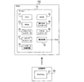
本実施形態のECU100は、ワンチップマイコンとして構成されたマイコン10を備えている(図1参照)。
[Description of configuration]
The ECU 100 of this embodiment includes a
マイコン10は、スリープ機能を有しており、スリープモード中は、マイコン10にメインクロックやサブクロックを供給する発振器の発振が停止される。また、スリープモードからの復帰(ウェイクアップ)に必要となる一部の部位を除き、マイコン10の各部位への電力供給が停止され、消費電力が低減された状態となる。
The
マイコン10は、CPU11,RAM12,ROM13と、割り込みコントローラ14,スタンバイコントローラ15,リセットコントローラ16,クロックコントローラ17,電源回路18,I/Oポート制御回路19等の周辺回路を備える。
The
CPU11は、RAM12にロードされたプログラムやROM13に記憶されているプログラムに従い動作し、各種処理を行う。
RAM12は、2以上の領域を有しており、これらの領域の少なくとも1つは、スリープモード中も電源回路18から電力が供給され、データの内容が保持されるバックアップ領域として構成されている。なお、バックアップ領域以外の他の領域については、スリープモード中、該領域のデータを保持するための電力が供給されず、データの内容が消失する。
The
The
割り込みコントローラ14は、マイコン10の周辺回路からの割り込み要求に応じてCPU11に割り込み信号を出力し、CPU11に割り込みプログラムを実行させる部位である。
The
割り込み信号を受信したCPU11のプログラムカウンタには、割り込み要求を発した周辺回路に対応付けられた状態で割り込みベクタテーブルに登録されている割り込みアドレスが設定される。そして、CPU11は、RAM12やROM13における該割り込みアドレスから始まる領域に記憶されている割り込みプログラムを実行する。
In the program counter of the
スタンバイコントローラ15は、スリープ機能に関する制御を行う部位であり、CPU11からスリープモードへの移行(スリープ)が指示された場合等には、スリープモードに移行するための制御を行う。
The
具体的には、クロックコントローラ17に対し、マイコン10を構成する各部位への内部クロックの供給を停止させると共に、発振器の発振を停止させる。また、電源回路18に対し、スリープモードからの復帰に最低限必要となる部位(スタンバイコントローラ15やRAM12のバックアップ領域等)以外の他の部位に対する電力供給の停止を指示する。
Specifically, the supply of the internal clock to each part constituting the
また、スタンバイコントローラ15は、スリープモード中、外部からの信号の入力等に起因して、スリープモードを解除する。
具体的には、クロックコントローラ17に対し、発振器の発振を開始させると共に、マイコン10の各部位への内部クロックの供給を開始させ、電源回路18に対し、マイコン10の各部位への電力供給の再開を指示する。また、リセットコントローラ16によりCPU11のリセットを行い、CPU11にブートアドレスから処理を実行させる。
Further, the
Specifically, the
リセットコントローラ16は、予め定められたリセット要因が発生すると、マイコン10の各部位をリセットする部位である。リセット要因としては、例えば、外部からのリセット信号の入力や、マイコン10への電力供給開始や、CPU11からの指示(リセットコントローラ16のレジスタに所定値が書き込まれた場合)や、マイコン10に電力を供給する電源の電圧低下等が考えられる。
The
リセットがなされると、CPU11のプログラムカウンタにブートアドレスが設定され、CPU11では、ROM13におけるブートアドレスから始まる領域に記憶されているブートプログラムが実行される。
When reset, the boot address is set in the program counter of the
クロックコントローラ17は、外部に設けられた発振器、又は、マイコン10に内臓された発振器からクロックの供給を受け、該クロックにより内部クロックを生成し、該内部クロックをCPU11等の各部位に供給する部位である。また、クロックコントローラ17は、クロックの供給源となる発振器の発振を制御する。
The
また、マイコン10には、メインクロックと、メインクロックよりも大幅に周波数が低いサブクロックとを供給可能となっている。クロックコントローラ17は、メインクロックとサブクロックの一方を選択し、選択したクロックの供給を受けて内部クロックを生成する。
In addition, the
電源回路18は、マイコン10の各部位に電力を供給する部位である。電源回路18は、マイコン10に電力を供給する電源の電圧が低下すると(マイコン10の電力供給端子に印可される電圧が閾値以下となると)、リセットコントローラ16によりCPU11のリセットを行い、CPU11にブートアドレスから処理を実行させる(ブートプログラムを実行させる)。
The
また、電源回路18は、スリープモード中は、スリープモードからの復帰に最低限必要となる部位(スタンバイコントローラ15とRAM12のバックアップ領域等)には電力供給を行うが、他の部位には電力供給を行わない。
In addition, during the sleep mode, the
I/Oポート制御回路19は、マイコン10に設けられたI/Oポートに関する制御を行う部位である。本実施形態では、一例として、リセット時にはI/OポートのレベルをLにし、スリープモード中はI/OポートのレベルをHにする。
The I / O
なお、CPU11により実行される上述したブートプログラム等を含むプログラムは、例えば、DVD,CD−ROM,USBメモリ,メモリカード(登録商標)等の光ディスク,磁気ディスク,半導体製メモリ等として構成された記憶媒体20に記憶された状態で提供することができる。無論、ネットワークを経由して提供されても良い。
The program including the above-described boot program executed by the
[動作の説明]
上述したように、本実施形態のECU100に搭載されたマイコン10では、スリープモード中は、CPU11等を含む大部分の部位への電力供給が停止されるため、消費電力が大幅に低減される。以後、これを電源遮断機能と記載する。
[Description of operation]
As described above, in the
そして、スリープモード中はCPU11への電力供給が停止されるため、ウェイクアップ時には、マイコン10への電力供給開始時等と同様にしてCPU11のリセットを行う必要がある。
Since the power supply to the
このため、マイコン10では、ウェイクアップ時に、リセットコントローラ16により、電力供給開始時等と同様にしてCPU11のリセットが行われる。これにより、ウェイクアップ時専用のCPU11のリセット回路を設ける必要が無くなり、マイコン10の回路の規模を低減することができる。
For this reason, in the
そして、ウェイクアップ時にリセットコントローラ16によりリセットがなされることにより、CPU11は、ウェイクアップ時に、電力供給開始時等と同様にしてブートアドレスから処理を実行することになる(ブートプログラムを実行することになる)。
Then, the reset is performed by the
以下では、マイコン10におけるブートプログラムについて、図2のフローチャートを用いて説明する。
S200では、マイコン10のCPU11は、スタンバイコントローラ15を制御するためのレジスタを参照し、実行中のブートプログラムが、ウェイクアップにより開始されたか否かを判定する。そして、肯定判定が得られた場合には(S200:Yes)、S205に処理を移行すると共に、否定判定が得られた場合には(S200:No)、S210に処理を移行する。
Below, the boot program in the
In S200, the
S205では、CPU11は、マイコン10のリセット時に対応する内容で初期化を行うリセット時初期化処理を実行し、本処理を終了する。なお、リセット時初期化処理では、例えば、RAM12の各アドレスに所定値を書き込むと共に、各アドレスから書き込んだ値を読み出すことができたかどうかをチェックする処理や、RAM12を初期化する処理等が行われる。このほかにも、例えば、電力供給の開始に伴うマイコン10の周辺回路等の初期化や、各パラメータの初期化等が行われる。
In S <b> 205, the
一方、S210では、CPU11は、スタンバイコントローラ15以外のマイコン10の他の周辺回路を制御するためのレジスタを参照し、実行中のブートプログラムが、ウェイクアップにより開始されたか否かを判定する。
On the other hand, in S210, the
以下に、該判定の具体例を挙げる。
(a)リセットコントローラ16のレジスタを参照し、リセット要因(例えば、リセット信号の入力や、マイコン10への電力供給開始や、CPU11からの指示や、マイコン10の電源の電圧低下等)を特定する。
Specific examples of the determination will be given below.
(A) Refer to the register of the
そして、リセット要因が特定できた場合には、マイコン10のリセットが生じたと判定し、そうでない場合には、ウェイクアップが生じたと判定する。
(b)電源回路18のレジスタを参照し、マイコン10の電源の電圧低下をリセット要因とするリセットが生じたか否かを判定する。そして、肯定判定が得られた場合には、リセットが生じたと判定し、否定判定が得られた場合には、ウェイクアップが生じたと判定する。
If the reset factor can be specified, it is determined that the
(B) The register of the
(c)クロックコントローラ17のレジスタを参照し、メインクロックの使用が許可されているか否かを判定する。
詳しく説明すると、マイコン10のリセットがなされると、クロックコントローラ17はメインクロックの使用が禁止された状態となるが、ウェイクアップの際には、クロックコントローラ17のリセットがなされず、クロックコントローラ17の状態が維持される。
(C) Refer to the register of the
More specifically, when the
また、本実施形態のECU100では、マイコン10はメインクロックにて動作するため、一旦リセットがなされると、例えばブートプログラム等でクロックコントローラ17のレジスタが設定され、メインクロックの使用が許可された状態となる。
In the
そして、スリープモード中やウェイクアップ時には、クロックコントローラ17では、メインクロックの使用が許可された状態が維持される。したがって、メインクロックの使用が許可されていれば、リセットは生じていないと判断できる。
During the sleep mode or during wakeup, the
このため、メインクロックの使用が許可されている場合には、ウェイクアップが生じたと判定し、そうでない場合には、リセットが生じたと判定する。
なお、仮に、マイコン10がサブクロックで動作するという場合には、クロックコントローラ17のレジスタを参照し、サブクロックの使用が許可されているか否かを判定することで、ウェイクアップが生じたか否かが判定される。
For this reason, when use of the main clock is permitted, it is determined that wake-up has occurred, and otherwise, it is determined that reset has occurred.
If the
また、クロックコントローラ17に限らず、ブートプログラム等による初期化処理によりリセット直後とは異なる状態に設定される周辺回路のレジスタの内容に基づき、ウェイクアップが生じたか否かを判定しても良い。
In addition to the
(d)I/Oポート制御回路19のレジスタを参照し、I/Oポートのレベルを判定する。そして、I/OポートのレベルがHである場合には、ウェイクアップが生じたと判定し、I/OポートのレベルがLである場合には、リセットが生じたと判定する。
(D) Referring to the register of the I / O
S210では、CPU11は、(a)〜(b)のうちの1つ又は複数の判定を行う。
なお、該判定にてレジスタの参照がなされる周辺回路は、マイコン10を構成する集積回路において、スタンバイコントローラ15と隣接して配置されていないか、スタンバイコントローラ15と一定の距離を隔てて配置されているのが好適である。
In S210, the
Note that the peripheral circuit to which the register is referenced in the determination is not arranged adjacent to the
こうすることにより、スタンバイコントローラ15に異常が生じたとしても、上記周辺回路がスタンバイコントローラ15の異常の影響を受け難くなり、ウェイクアップが生じたか否かの判定を精度良く行うことが可能となる。
By doing so, even if an abnormality occurs in the
そして、この1つの判定、又は、複数の判定のうちの全てで、ウェイクアップが生じたと判定された場合には(S210:Yes)、S215に処理を移行し、そうでない場合には(S210:No)、S205に処理を移行する。 If it is determined that wake-up has occurred in all of the one determination or the plurality of determinations (S210: Yes), the process proceeds to S215, and if not (S210: No), the process proceeds to S205.
S215では、CPU11は、ウェイクアップに対応する内容で初期化を行うウェイクアップ時初期化処理を実行し、本処理を終了する。なお、ウェイクアップ時初期化処理では、例えば、ウェイクアップに伴うマイコン10の周辺回路等の初期化や、各パラメータの初期化等が行われる。また、RAM12におけるバックアップ領域に保存されたデータの内容によりスリープ前の状態が復元され、スリープ前と同様にして処理が行われる。
In S215, the
[効果]
本実施形態のマイコン10によれば、リセット時とウェイクアップ時とに実行されるブートプログラムでは、スタンバイコントローラ15のみならず、他の周辺回路の状態に基づきブートプログラムが開始された要因が判定される。
[effect]
According to the
そして、スタンバイコントローラ15に何等かの異常が生じ、ウェイクアップがブートプログラムの開始要因であると誤判定された場合であっても、他の周辺回路の状態に基づきリセットが開始要因と判定されれば、リセットに対応する内容の初期化が行われる。
Even if some abnormality occurs in the
したがって、マイコン10をより確実に意図通りに起動させることができる。
また、ブートプログラムでは、リセットコントローラ16と、電源回路18と、クロックコントローラ17と、I/Oポート制御回路19とのうちの少なくとも1つの状態に基づき、リセットとウェイクアップのどちらが生じたかが判定される。
Therefore, the
In the boot program, it is determined whether a reset or a wake-up has occurred based on at least one state of the
このため、より確実に、ウェイクアップが生じたか否かを判定することができる。
[他の実施形態]
(1)本実施形態では、一例としてECU100に搭載されたマイコン10を例示して説明を行ったが、車両に搭載されない制御装置に搭載される電源遮断機能付きのマイコンにおいても、本実施形態と同様のブートプログラムを実行することが考えられる。このような場合であっても、同様の効果を得ることができる。
For this reason, it can be determined more reliably whether or not wake-up has occurred.
[Other Embodiments]
(1) In the present embodiment, the
(2)また、本実施形態のマイコン10は、一例としてワンチップマイコンとして構成されている。しかしながら、これに限らず、CPUと、ROM,RAM,周辺回路の全部又は一部とが異なるチップに搭載されている場合であっても、本発明を提供することができる。このような場合であっても、本実施形態と同様のブートプログラムを実行することで、同様の効果を得ることができる。
(2) Moreover, the
(3)また、本実施形態のブートプログラムのS210では、スタンバイコントローラ15以外のマイコン10の他の周辺回路の状態に基づき、ウェイクアップが生じたことによりブートプログラムが開始されたか否かが判定される。しかしながら、これに限らず、マイコン10に接続される外部回路の状態に基づき、同様の判定を行っても良い。
(3) In S210 of the boot program of the present embodiment, it is determined whether or not the boot program is started due to the occurrence of wake-up based on the state of other peripheral circuits of the
具体的には、例えば、ECU100の各部位に電力を供給する電源回路の状態に基づき、自車両の運転開始による電力供給状態の変化が生じたか否かを判定しても良い。そして、このような変化が生じたと判定された場合には、ウェイクアップが生じたとみなし、そうでない場合には、リセットが生じたとみなしても良い。
Specifically, for example, based on the state of a power supply circuit that supplies power to each part of the
このような場合であっても、同様の効果を得ることができる。
(4)また、本実施形態のマイコン10は、電源遮断機能付きマイコンとして構成されている。しかしながら、これに限らず、本発明は、電源遮断機能が設けられていなくても、ウェイクアップ時とリセット時とで同一のブートプログラムが実行されるマイコンにも適用することができる。
Even in such a case, the same effect can be obtained.
(4) Moreover, the
(5)また、本実施形態では、ブートプログラムのS210におけるウェイクアップが生じたか否かの判定の具体例として、(a)〜(d)の具体例を挙げた。
しかしながら、当該判定は、(a)〜(d)以外の方法で行っても良く、各判定にて参照される要因は重複していても良い(例えば、同一の周辺回路における異なるレジスタを参照することで判定がなされるような場合であっても良い)。
(5) In the present embodiment, specific examples of (a) to (d) are given as specific examples of determining whether or not the wakeup in S210 of the boot program has occurred.
However, the determination may be performed by a method other than (a) to (d), and the factors referred to in each determination may overlap (for example, refer to different registers in the same peripheral circuit). It may be a case where the determination is made by this).
このような場合であっても、同様の効果を得ることができる。
[特許請求の範囲との対応]
上記実施形態の説明で用いた用語と、特許請求の範囲の記載に用いた用語との対応を示す。
Even in such a case, the same effect can be obtained.
[Correspondence with Claims]
The correspondence between the terms used in the description of the above embodiment and the terms used in the description of the claims is shown.
ECU100が制御装置の一例に、マイコン10が制御部の一例に、スタンバイコントローラ15が復帰回路の一例に、リセットコントローラ16がリセット回路の一例に、クロックコントローラ17がクロック制御回路の一例に、I/Oポート制御回路19がポート制御回路の一例に相当する。
The
また、ブートプログラムのS200が第1判定処理,第1判定手段の一例に、S205,S215が初期化処理,初期化手段の一例に、S210が第2判定処理,第2判定手段の一例に相当する。 Further, S200 of the boot program corresponds to an example of the first determination process and the first determination unit, S205 and S215 correspond to an example of the initialization process and the initialization unit, and S210 corresponds to an example of the second determination process and the second determination unit. To do.
また、スリープモードが、低消費電力モードの一例に相当する。 The sleep mode corresponds to an example of a low power consumption mode.
10…マイコン、11…CPU、12…RAM、13…ROM、14…割り込みコントローラ、15…スタンバイコントローラ、16…リセットコントローラ、17…クロックコントローラ、18…電源回路、19…I/Oポート制御回路、100…ECU。
DESCRIPTION OF
Claims (4)
前記制御部は、
プログラムを実行し、各種処理を行うCPU(11)と、
予め定められた条件が充足されると、当該制御部をリセットし、前記CPUに初期化プログラムを実行させるリセット回路(16)と、
当該制御部を、消費電力を抑えた状態である低消費電力モードから復帰させ、前記CPUに前記初期化プログラムを実行させる復帰回路(15)と、
を備え、
前記初期化プログラムは、
前記復帰回路の状態に基づき、当該初期化プログラムが開始された要因を判定する第1判定処理(S200)と、
前記制御装置に設けられた前記復帰回路以外の他の回路の状態に基づき、当該初期化プログラムが開始された要因を判定する第2判定処理(S210)と、
前記第1判定処理と前記第2判定処理とのうちの少なくとも一方で、前記リセットを要因として当該初期化プログラムが開始されたと判定された場合には、前記リセットに対応する内容の初期化を行うと共に、そうでない場合には、前記低消費電力モードからの復帰に対応する内容の初期化を行う初期化処理(S205,S215)と、
を有することを特徴とする制御装置。 A control device (100) including a control unit (10) for performing various controls and an external circuit,
The controller is
A CPU (11) that executes a program and performs various processes;
A reset circuit (16) for resetting the control unit and causing the CPU to execute an initialization program when a predetermined condition is satisfied;
A return circuit (15) for returning the control unit from a low power consumption mode in which power consumption is suppressed and causing the CPU to execute the initialization program;
With
The initialization program is
A first determination process (S200) for determining a factor of starting the initialization program based on the state of the return circuit;
A second determination process (S210) for determining a factor of starting the initialization program based on a state of a circuit other than the return circuit provided in the control device;
If at least one of the first determination process and the second determination process determines that the initialization program is started due to the reset, the contents corresponding to the reset are initialized. If not, an initialization process (S205, S215) for initializing contents corresponding to the return from the low power consumption mode,
A control device comprising:
前記第2判定処理での判定に係る前記他の回路とは、前記制御部に設けられた回路であること、
を特徴とする制御装置。 The control device according to claim 1,
The other circuit related to the determination in the second determination process is a circuit provided in the control unit,
A control device characterized by.
前記第2判定処理において、前記リセット回路の状態と、前記制御部を構成する各部位への電力供給を制御する電源回路(18)の状態と、前記CPUに入力されるクロックに関する制御を行うクロック制御回路(17)の状態と、前記制御部に設けられたポートの状態を制御するポート制御回路(19)の状態とのうちの少なくとも1つに基づき、前記低消費電力モードからの復帰か否かを判定すること、
を特徴とする制御装置。 The control device according to claim 2,
In the second determination process, the state of the reset circuit, the state of the power supply circuit (18) for controlling the power supply to each part constituting the control unit, and a clock for controlling the clock input to the CPU Whether to return from the low power consumption mode based on at least one of the state of the control circuit (17) and the state of the port control circuit (19) that controls the state of the port provided in the control unit. To determine whether
A control device characterized by.
前記制御部は、
予め定められた条件が充足されると、当該制御部をリセットし、前記CPUに初期化プログラムを実行させるリセット回路(16)と、
当該制御部を、消費電力を抑えた状態である低消費電力モードから復帰させ、前記CPUに前記初期化プログラムを実行させる復帰回路(15)と、
を備え、
前記初期化プログラムは、
前記復帰回路の状態に基づき、当該初期化プログラムが開始された要因を判定する第1判定手段(S200)と、
前記制御装置に設けられた前記復帰回路以外の他の回路の状態に基づき、当該初期化プログラムが開始された要因を判定する第2判定手段(S210)と、
前記第1判定手段と前記第2判定手段とのうちの少なくとも一方で、前記リセットを要因として当該初期化プログラムが開始されたと判定された場合には、前記リセットに対応する内容の初期化を行うと共に、そうでない場合には、前記低消費電力モードからの復帰に対応する内容の初期化を行う初期化手段(S205,S215)として、
前記CPUを動作させることを特徴とする初期化プログラム。 An initialization program for causing a CPU (11) provided in the control unit in a control device (100) including various control units and an external circuit to initialize the control unit,
The controller is
A reset circuit (16) for resetting the control unit and causing the CPU to execute an initialization program when a predetermined condition is satisfied;
A return circuit (15) for returning the control unit from a low power consumption mode in which power consumption is suppressed and causing the CPU to execute the initialization program;
With
The initialization program is
First determination means (S200) for determining a factor of starting the initialization program based on the state of the return circuit;
Second determination means (S210) for determining a factor that the initialization program is started based on a state of a circuit other than the return circuit provided in the control device;
When at least one of the first determination unit and the second determination unit determines that the initialization program is started due to the reset, the contents corresponding to the reset are initialized. If not, initialization means (S205, S215) for initializing the contents corresponding to the return from the low power consumption mode,
An initialization program for operating the CPU.
Priority Applications (1)
| Application Number | Priority Date | Filing Date | Title |
|---|---|---|---|
| JP2014042775A JP6229552B2 (en) | 2014-03-05 | 2014-03-05 | Control device and initialization program |
Applications Claiming Priority (1)
| Application Number | Priority Date | Filing Date | Title |
|---|---|---|---|
| JP2014042775A JP6229552B2 (en) | 2014-03-05 | 2014-03-05 | Control device and initialization program |
Publications (2)
| Publication Number | Publication Date |
|---|---|
| JP2015170006A JP2015170006A (en) | 2015-09-28 |
| JP6229552B2 true JP6229552B2 (en) | 2017-11-15 |
Family
ID=54202726
Family Applications (1)
| Application Number | Title | Priority Date | Filing Date |
|---|---|---|---|
| JP2014042775A Active JP6229552B2 (en) | 2014-03-05 | 2014-03-05 | Control device and initialization program |
Country Status (1)
| Country | Link |
|---|---|
| JP (1) | JP6229552B2 (en) |
Families Citing this family (2)
| Publication number | Priority date | Publication date | Assignee | Title |
|---|---|---|---|---|
| JP7220071B2 (en) * | 2018-12-21 | 2023-02-09 | 株式会社デンソーテン | Control device and control method |
| CN117149478B (en) * | 2023-06-14 | 2024-06-04 | 杭州迪为科技有限公司 | Reset management method and device of automobile electronic controller and automobile electronic controller |
Family Cites Families (2)
| Publication number | Priority date | Publication date | Assignee | Title |
|---|---|---|---|---|
| US20130067258A1 (en) * | 2010-05-20 | 2013-03-14 | Toshiaki Furuya | Data processor and electronic control unit |
| JP5660010B2 (en) * | 2011-11-21 | 2015-01-28 | トヨタ自動車株式会社 | Information processing apparatus and data restoration method |
-
2014
- 2014-03-05 JP JP2014042775A patent/JP6229552B2/en active Active
Also Published As
| Publication number | Publication date |
|---|---|
| JP2015170006A (en) | 2015-09-28 |
Similar Documents
| Publication | Publication Date | Title |
|---|---|---|
| CN109739563B (en) | Terminal control method, device, system and storage medium | |
| CN104102325B (en) | Memorizer control circuit | |
| JP5093620B2 (en) | Platform-based idle time processing | |
| JP4536742B2 (en) | Arithmetic processing apparatus and method for flash memory according to priority | |
| US9658863B2 (en) | Information processing apparatus and control method therefor | |
| TW201519253A (en) | System single chip for reducing wake-up time, method for operating system single chip, and computer system including system single chip | |
| JP2004334486A (en) | Starting system using boot code and starting method | |
| KR20150029688A (en) | Secure data protection with improved read-only memory locking during system pre-boot | |
| KR20090009018A (en) | Computer equipped with flash memory and driving method of flash memory | |
| JP2006276967A (en) | Semiconductor apparatus | |
| JP2013225208A (en) | Information processing apparatus, information processing method and program | |
| JP6229552B2 (en) | Control device and initialization program | |
| US10108469B2 (en) | Microcomputer and microcomputer system | |
| US9778981B2 (en) | Microcontroller | |
| CA2658634A1 (en) | Controlled frequency core processor and method for starting-up said core processor in a programmed manner | |
| US20200117261A1 (en) | Backup power supply based configuration data application | |
| JP5660010B2 (en) | Information processing apparatus and data restoration method | |
| JP6172040B2 (en) | Electronic control unit | |
| JP2006079230A (en) | Semiconductor circuit device and runaway detecting method | |
| JP2012173919A (en) | Information processor, electronic control unit for vehicle, and data storage method | |
| JP4647276B2 (en) | Semiconductor circuit device | |
| KR20080057688A (en) | How to Boot an Operating System Using Nonvolatile Memory | |
| JP6332091B2 (en) | Electronic control unit | |
| KR101236393B1 (en) | Electric device and control method thereof | |
| JP4702343B2 (en) | Mobile terminal device |
Legal Events
| Date | Code | Title | Description |
|---|---|---|---|
| A621 | Written request for application examination |
Free format text: JAPANESE INTERMEDIATE CODE: A621 Effective date: 20160620 |
|
| A131 | Notification of reasons for refusal |
Free format text: JAPANESE INTERMEDIATE CODE: A131 Effective date: 20170627 |
|
| TRDD | Decision of grant or rejection written | ||
| A01 | Written decision to grant a patent or to grant a registration (utility model) |
Free format text: JAPANESE INTERMEDIATE CODE: A01 Effective date: 20170919 |
|
| A61 | First payment of annual fees (during grant procedure) |
Free format text: JAPANESE INTERMEDIATE CODE: A61 Effective date: 20171002 |
|
| R151 | Written notification of patent or utility model registration |
Ref document number: 6229552 Country of ref document: JP Free format text: JAPANESE INTERMEDIATE CODE: R151 |
|
| R250 | Receipt of annual fees |
Free format text: JAPANESE INTERMEDIATE CODE: R250 |
|
| R250 | Receipt of annual fees |
Free format text: JAPANESE INTERMEDIATE CODE: R250 |
|
| R250 | Receipt of annual fees |
Free format text: JAPANESE INTERMEDIATE CODE: R250 |
|
| R250 | Receipt of annual fees |
Free format text: JAPANESE INTERMEDIATE CODE: R250 |
|
| R250 | Receipt of annual fees |
Free format text: JAPANESE INTERMEDIATE CODE: R250 |
|
| R250 | Receipt of annual fees |
Free format text: JAPANESE INTERMEDIATE CODE: R250 |