JP6224552B2 - Barbecue grill - Google Patents
Barbecue grill Download PDFInfo
- Publication number
- JP6224552B2 JP6224552B2 JP2014174968A JP2014174968A JP6224552B2 JP 6224552 B2 JP6224552 B2 JP 6224552B2 JP 2014174968 A JP2014174968 A JP 2014174968A JP 2014174968 A JP2014174968 A JP 2014174968A JP 6224552 B2 JP6224552 B2 JP 6224552B2
- Authority
- JP
- Japan
- Prior art keywords
- rib
- frame
- leg
- support leg
- frames
- Prior art date
- Legal status (The legal status is an assumption and is not a legal conclusion. Google has not performed a legal analysis and makes no representation as to the accuracy of the status listed.)
- Active
Links
Images


Landscapes
- Baking, Grill, Roasting (AREA)
Description
本発明は、バーベキューグリルに関する。 The present invention relates to a barbecue grill.
従来のバーベキューグリルが下記特許文献1に記載されている。この従来のバーベキューグリルは、下向き略U字状の第1、第2支持脚と、第1、第2横パイプと、第1、第2プレートと、火床とを備えている。第1、第2支持脚は、当該バーベキューグリルの長手方向において互いに対向するように配置されている。第1、第2支持脚の上端部は、当該バーベキューグリルの端手方向の第1、第2端部を有している。火床は、第1、第2支持脚の上端部に懸架されている。 A conventional barbecue grill is described in Patent Document 1 below. This conventional barbecue grill includes first and second support legs that are substantially U-shaped downward, first and second horizontal pipes, first and second plates, and a firebed. The first and second support legs are arranged to face each other in the longitudinal direction of the barbecue grill. The upper ends of the first and second support legs have first and second ends in the end-hand direction of the barbecue grill. The fire bed is suspended from the upper ends of the first and second support legs.
第1プレートの長手方向の第1端が第1支持脚の上端部の第1端部に外側から取り付けられ、第1プレートの長手方向の第2端が第2支持脚の上端部の第1端部に外側から取り付けられている。第2プレートの長手方向の第1端が第1支持脚の上端部の第2端部に外側から取り付けられ、第2プレートの長手方向の第2端が第2支持脚の上端部の第2端部に外側から取り付けられている。第1、第2プレートが火床の側面に間隙を有して配置され、バーベキューグリルの使用者が火床に触れるのを防止している。 The first end in the longitudinal direction of the first plate is attached to the first end of the upper end of the first support leg from the outside, and the second end in the longitudinal direction of the first plate is the first of the upper end of the second support leg. It is attached to the end from the outside. The first end of the second plate in the longitudinal direction is attached to the second end of the upper end of the first support leg from the outside, and the second end of the second plate in the longitudinal direction is the second end of the upper end of the second support leg. It is attached to the end from the outside. The first and second plates are disposed with a gap on the side surface of the fire bed to prevent the user of the barbecue grill from touching the fire bed.
第1横パイプの長手方向の第1端が第1支持脚の上端部の第1端部に内側から取り付けられ、第1横パイプの長手方向の第2端が第2支持脚の上端部の第1端部に内側から取り付けられている。第2横パイプの長手方向の第1端が第1支持脚の上端部の第2端部に内側から取り付けられ、第2横パイプの長手方向の第2端が第2支持脚の上端部の第2端部に内側から取り付けられている。このように第1、第2横パイプが第1、第2支持脚を連結することによって、第1、第2プレートの捩じれを防止している。 The first end of the first horizontal pipe in the longitudinal direction is attached to the first end of the upper end of the first support leg from the inside, and the second end of the first horizontal pipe in the longitudinal direction of the upper end of the second support leg. The first end is attached from the inside. The first end of the second horizontal pipe in the longitudinal direction is attached to the second end of the upper end of the first support leg from the inside, and the second end of the second horizontal pipe in the longitudinal direction of the upper end of the second support leg. The second end is attached from the inside. In this way, the first and second horizontal pipes connect the first and second support legs to prevent the first and second plates from being twisted.
上記の通り、従来のバーベキューグリルは、第1、第2支持脚、第1、第2横パイプ及び第1、第2プレートが必須であるため、部品点数が多い。 As described above, the conventional barbecue grill has a large number of parts because the first and second support legs, the first and second horizontal pipes, and the first and second plates are essential.
本発明は、上記事情に鑑みて創案されたものであって、その目的とするところは、部品点数の低減を図ることができるバーベキューグリルを提供することにある。 The present invention has been made in view of the above circumstances, and an object of the present invention is to provide a barbecue grill capable of reducing the number of parts.
上記課題を解決するために、本発明のバーベキューグリルは、第1、第2フレームと、第1、第2支持脚とを備えている。第1、第2フレームは、第1方向において互いに間隔をあけて対向している。第1、第2フレームは、フレーム本体と、第1、第2リブと、第3、第4リブとを有している。フレーム本体は、第1方向に交差する第2方向に延びた筒であって、第2方向の第1端部および第1端部の反対側の第2端部を有し、且つ第1端部が第2方向の一方に開放され、第2端部が第2方向の他方に開放されている。第1リブは、フレーム本体の第1端部の内面又は外面上に設けられている。第2リブは、フレーム本体の第1端部の内面又は外面上に設けられている。第3リブは、フレーム本体の第2端部の内面又は外面上に設けられている。第4リブは、フレーム本体の第2端部の内面又は外面上に設けられている。第1支持脚は、第1、第2脚部と、連結部とを有している。第1支持脚の第1脚部は、第1フレームの第1、第2リブに固定されている。第1支持脚の第2脚部は、第2フレームの第1、第2リブに固定されている。第1支持脚の連結部は、第1支持脚の第1、第2脚部を連結している。第2支持脚は、第1、第2脚部と、連結部とを有している。第2支持脚の第1脚部は、第1フレームの第3、第4リブに固定されている。第2支持脚の第2脚部は、第2フレームの第3、第4リブに固定されている。第2支持脚の連結部は、第2支持脚の第1、第2脚部を連結している。 In order to solve the above problems, the barbecue grill of the present invention includes first and second frames and first and second support legs. The first and second frames oppose each other with a gap in the first direction. The first and second frames have a frame body, first and second ribs, and third and fourth ribs. The frame body is a tube extending in a second direction intersecting the first direction, and has a first end in the second direction and a second end opposite to the first end, and the first end The part is open to one side in the second direction, and the second end is open to the other side in the second direction . The first rib is provided on the inner surface or the outer surface of the first end of the frame body. The second rib is provided on the inner surface or the outer surface of the first end portion of the frame body. The third rib is provided on the inner surface or the outer surface of the second end portion of the frame body. The fourth rib is provided on the inner surface or the outer surface of the second end portion of the frame body. The first support leg has first and second leg portions and a connecting portion. The first leg portion of the first support leg is fixed to the first and second ribs of the first frame. The second leg portion of the first support leg is fixed to the first and second ribs of the second frame. The connecting portion of the first support leg connects the first and second leg portions of the first support leg. The second support leg has first and second leg portions and a connecting portion. The first leg portion of the second support leg is fixed to the third and fourth ribs of the first frame. The second leg portion of the second support leg is fixed to the third and fourth ribs of the second frame. The connecting portion of the second support leg connects the first and second leg portions of the second support leg.
このような態様のバーベキューグリルは、以下の技術的特徴及び効果を有する。第1に、バーベキューグリルの部品点数の低減を図ることができる。第1、第2支持脚が、少なくとも第1、第2フレームで連結される構成とすることが可能である。第2に、第1、第2フレームのみで第1、第2支持脚を連結したとしても、第1、第2フレームに歪みが生じ難い。なぜなら、第1、第2フレームのフレーム本体が筒であるからである。第3に、第1、第2フレームの断熱効果を向上させることができる。第1、第2フレームのフレーム本体が筒であり、内部に空気層を有しているからである。第4に、バーベキューグリルの重量の増加を抑制することができる。第1、第2フレームが筒であるフレーム本体の内面又は外面に第1〜第4リブが設けられた構成であるからである。 The barbecue grill of such an aspect has the following technical features and effects. First, the number of parts of the barbecue grill can be reduced. The first and second support legs may be connected by at least the first and second frames. Second, even if the first and second support legs are connected only by the first and second frames, the first and second frames are hardly distorted. This is because the frame main bodies of the first and second frames are cylinders. Thirdly, the heat insulation effect of the first and second frames can be improved. This is because the frame main bodies of the first and second frames are cylinders and have an air layer inside. Fourth, an increase in the weight of the barbecue grill can be suppressed. This is because the first and fourth ribs are provided on the inner surface or outer surface of the frame main body in which the first and second frames are cylinders.
本発明の別のバーベキューグリルは、第1方向において互いに間隔をあけて対向する第1、第2フレームと、第1、第2支持脚とを備えている。第1、第2フレームは、第1方向に交差する第2方向に延びた多角形状の筒であって、第1、第2角を更に有するフレーム本体と、フレーム本体の第1角の第2方向の第1端部の内面又は外面上に設けられた第1リブと、フレーム本体の第2角の第2方向の第1端部の内面又は外面上に設けられた第2リブと、フレーム本体の第1角の第1端部の反対側の第2端部の内面又は外面上に設けられた第3リブと、フレーム本体の第2角の第1端部の反対側の第2端部の内面又は外面上に設けられた第4リブとを有している。第1支持脚は、第1フレームの第1リブ及び第2リブに固定された第1脚部と、第2フレームの第1リブ及び第2リブに固定された第2脚部と、第1脚部と第2脚部とを連結する連結部とを有している。第2支持脚は、第1フレームの第3リブ及び第4リブに固定された第1脚部と、第2フレームの第3リブ及び第4リブに固定された第2脚部と、当該第2支持脚の第1脚部と第2脚部とを連結する連結部とを有している。Another barbecue grill according to the present invention includes first and second frames and first and second support legs that face each other with a gap in the first direction. The first and second frames are polygonal cylinders extending in a second direction intersecting the first direction, and include a frame main body further having first and second corners, and a second first corner of the frame main body. A first rib provided on the inner surface or outer surface of the first end portion in the direction, a second rib provided on the inner surface or outer surface of the first end portion in the second direction of the second corner of the frame body, and the frame A third rib provided on the inner or outer surface of the second end opposite to the first end of the first corner of the main body, and a second end opposite to the first end of the second corner of the frame main body; And a fourth rib provided on the inner or outer surface of the part. The first support leg includes a first leg fixed to the first rib and the second rib of the first frame, a second leg fixed to the first rib and the second rib of the second frame, and a first leg. It has a connection part which connects a leg part and the 2nd leg part. The second support leg includes a first leg fixed to the third rib and the fourth rib of the first frame, a second leg fixed to the third rib and the fourth rib of the second frame, and the second leg. 2 It has the connection part which connects the 1st leg part of a support leg, and a 2nd leg part.
このような態様のバーベキューグリルは、以下の技術的特徴及び効果を有する。第1に、バーベキューグリルの部品点数の低減を図ることができる。第1、第2支持脚が、少なくとも第1、第2フレームで連結される構成とすることが可能である。第2に、第1、第2フレームのみで第1、第2支持脚を連結したとしても、第1、第2フレームに歪みが生じ難い。なぜなら、第1、第2フレームのフレーム本体が筒であるからである。第3に、第1、第2フレームの断熱効果を向上させることができる。第1、第2フレームのフレーム本体が筒であり、内部に空気層を有しているからである。第4に、バーベキューグリルの重量の増加を抑制することができる。第1、第2フレームが筒であるフレーム本体の内面又は外面に第1〜第4リブが設けられた構成であるからである。第5に、更に第1、第2フレームに歪みが生じ難くなる。その理由は以下の通りである。第1、第2リブがフレーム本体の第1、第2角の第1端部の内面又は外面上に設けられることによって、当該第1、第2リブがフレーム本体を補強している。第3、第4リブがフレーム本体の第1、第2角の第2端部の内面又は外面上に設けられることによって、当該第3、第4リブがフレーム本体を補強している。 The barbecue grill of such an aspect has the following technical features and effects. First, the number of parts of the barbecue grill can be reduced. The first and second support legs may be connected by at least the first and second frames. Second, even if the first and second support legs are connected only by the first and second frames, the first and second frames are hardly distorted. This is because the frame main bodies of the first and second frames are cylinders. Thirdly, the heat insulation effect of the first and second frames can be improved. This is because the frame main bodies of the first and second frames are cylinders and have an air layer inside. Fourth, an increase in the weight of the barbecue grill can be suppressed. This is because the first and fourth ribs are provided on the inner surface or outer surface of the frame main body in which the first and second frames are tubes. Fifth, distortion is less likely to occur in the first and second frames. The reason is as follows. The first and second ribs reinforce the frame body by providing the first and second ribs on the inner or outer surface of the first end of the first and second corners of the frame body. The third and fourth ribs reinforce the frame body by being provided on the inner or outer surface of the second end of the first and second corners of the frame body.
本発明の別のバーベキューグリルは、第1方向において互いに間隔をあけて対向する第1、第2フレームと、第1、第2支持脚とを備えている。第1、第2フレームは、第1方向に交差する第2方向に延びた筒であるフレーム本体と、第1、第2長尺リブとを有している。第1長尺リブは、第1、第2フレームのフレーム本体の内面又は外面上に設けられており且つ当該内面又は外面の第2方向の一端から他端にかけて第2方向に延びており、且つ第1長尺リブの第2方向の第1端部である第1リブと第1長尺リブの第1端部の反対側の第2端部である第3リブとを有している。第2長尺リブは、第1、第2フレームのフレーム本体の内面又は外面上に設けられており且つ当該内面又は外面の第2方向の一端から他端にかけて第2方向に延びており、且つ第2長尺リブの第2方向の第1端部である第2リブと第2長尺リブの第1端部の反対側の第2端部である第4リブとを有している。第1支持脚は、第1フレームの第1リブ及び第2リブに固定された第1脚部と、第2フレームの第1リブ及び第2リブに固定された第2脚部と、第1脚部と第2脚部とを連結する連結部とを有している。第2支持脚は、第1フレームの第3リブ及び第4リブに固定された第1脚部と、第2フレームの第3リブ及び第4リブに固定された第2脚部と、当該第2支持脚の第1脚部と第2脚部とを連結する連結部とを有している。 Another barbecue grill according to the present invention includes first and second frames and first and second support legs that face each other with a gap in the first direction. The first and second frames have a frame body that is a cylinder extending in a second direction intersecting the first direction, and first and second long ribs. The first long rib is provided on the inner or outer surface of the frame body of the first and second frames, and extends in the second direction from one end to the other end of the inner or outer surface in the second direction; and It has the 1st rib which is the 1st end part of the 2nd direction of the 1st long rib, and the 3rd rib which is the 2nd end part on the opposite side to the 1st end part of the 1st long rib. The second long rib is provided on the inner surface or the outer surface of the frame body of the first and second frames, and extends in the second direction from one end to the other end of the inner surface or the outer surface in the second direction, and It has the 2nd rib which is the 1st end part of the 2nd direction of the 2nd long rib, and the 4th rib which is the 2nd end part on the opposite side to the 1st end part of the 2nd long rib. The first support leg includes a first leg fixed to the first rib and the second rib of the first frame, a second leg fixed to the first rib and the second rib of the second frame, and a first leg. It has a connection part which connects a leg part and the 2nd leg part. The second support leg includes a first leg fixed to the third rib and the fourth rib of the first frame, a second leg fixed to the third rib and the fourth rib of the second frame, and the second leg. 2 It has the connection part which connects the 1st leg part of a support leg, and a 2nd leg part.
このような態様のバーベキューグリルは、以下の技術的特徴及び効果を有する。第1に、バーベキューグリルの部品点数の低減を図ることができる。第1、第2支持脚が、少なくとも第1、第2フレームで連結される構成とすることが可能である。第2に、第1、第2フレームのみで第1、第2支持脚を連結したとしても、第1、第2フレームに歪みが生じ難い。なぜなら、第1、第2フレームのフレーム本体が筒であるからである。第3に、第1、第2フレームの断熱効果を向上させることができる。第1、第2フレームのフレーム本体が筒であり、内部に空気層を有しているからである。第4に、バーベキューグリルの重量の増加を抑制することができる。第1、第2フレームが筒であるフレーム本体の内面又は外面に第1〜第4リブが設けられた構成であるからである。第5に、更に第1、第2フレームに歪みが生じ難くなる。第1、第2長尺リブがフレーム本体を補強しているからである。 The barbecue grill of such an aspect has the following technical features and effects. First, the number of parts of the barbecue grill can be reduced. The first and second support legs may be connected by at least the first and second frames. Second, even if the first and second support legs are connected only by the first and second frames, the first and second frames are hardly distorted. This is because the frame main bodies of the first and second frames are cylinders. Thirdly, the heat insulation effect of the first and second frames can be improved. This is because the frame main bodies of the first and second frames are cylinders and have an air layer inside. Fourth, an increase in the weight of the barbecue grill can be suppressed. This is because the first and fourth ribs are provided on the inner surface or outer surface of the frame main body in which the first and second frames are tubes. Fifth, distortion is less likely to occur in the first and second frames. This is because the first and second long ribs reinforce the frame body.
第1長尺リブがフレーム本体の第1角の内面又は外面上に設けられた構成とすることが可能である。第2長尺リブがフレーム本体の第2角の内面又は外面上に設けられた構成とすることが可能である。 The first long rib may be provided on the inner surface or the outer surface of the first corner of the frame body. The second long rib may be provided on the inner surface or the outer surface of the second corner of the frame body.
このような態様のバーベキューグリルは、更に第1、第2フレームに歪みが生じ難くなる。第1、第2長尺リブがフレーム本体の第1、第2角の内面又は外面上に設けられ、当該フレーム本体を補強しているからである。 In the barbecue grill of this aspect, the first and second frames are less likely to be distorted. This is because the first and second long ribs are provided on the inner or outer surfaces of the first and second corners of the frame body to reinforce the frame body.
本発明の別のバーベキューグリルは、第1方向において互いに間隔をあけて対向する第1、第2フレームと、第1、第2支持脚とを備えている。第1、第2フレームは、第1方向に交差する第2方向に延びた筒であるフレーム本体と、第3、第4長尺リブとを有している。第3長尺リブは、前記第1、第2フレームのフレーム本体の第1端部の内面又は外面上に設けられており且つ当該フレーム本体の周方向に延びており、且つ第3長尺リブの長さ方向の第1端部である第1リブと第3長尺リブの第1端部の反対側の第2端部である第2リブとを有している。第4長尺リブは、前記第1、第2フレームのフレーム本体の第2端部の内面又は外面上に設けられており且つ当該フレーム本体の周方向に延びており、且つ第4長尺リブの長さ方向の第1端部である第3リブと第4長尺リブの第1端部の反対側の第2端部である第4リブとを有している。第1支持脚は、第1フレームの第1リブ及び第2リブに固定された第1脚部と、第2フレームの第1リブ及び第2リブに固定された第2脚部と、第1脚部と第2脚部とを連結する連結部とを有している。第2支持脚は、第1フレームの第3リブ及び第4リブに固定された第1脚部と、第2フレームの第3リブ及び第4リブに固定された第2脚部と、当該第2支持脚の第1脚部と第2脚部とを連結する連結部とを有している。
このような態様のバーベキューグリルは、以下の技術的特徴及び効果を有する。第1に、バーベキューグリルの部品点数の低減を図ることができる。第1、第2支持脚が、少なくとも第1、第2フレームで連結される構成とすることが可能である。第2に、第1、第2フレームのみで第1、第2支持脚を連結したとしても、第1、第2フレームに歪みが生じ難い。なぜなら、第1、第2フレームのフレーム本体が筒であるからである。第3に、第1、第2フレームの断熱効果を向上させることができる。第1、第2フレームのフレーム本体が筒であり、内部に空気層を有しているからである。第4に、バーベキューグリルの重量の増加を抑制することができる。第1、第2フレームが筒であるフレーム本体の内面又は外面に第1〜第4リブが設けられた構成であるからである。
Another barbecue grill according to the present invention includes first and second frames and first and second support legs that face each other with a gap in the first direction. The first and second frames have a frame body that is a cylinder extending in a second direction intersecting the first direction, and third and fourth long ribs. The third long rib is provided on the inner surface or the outer surface of the first end of the frame main body of the first and second frames and extends in the circumferential direction of the frame main body, and the third long rib. A first rib that is a first end portion in the length direction and a second rib that is a second end portion opposite to the first end portion of the third long rib. The fourth long rib is provided on the inner surface or the outer surface of the second end of the frame main body of the first and second frames and extends in the circumferential direction of the frame main body, and the fourth long rib. The third rib, which is the first end portion in the length direction, and the fourth rib, which is the second end portion on the opposite side of the first end portion of the fourth long rib. The first support leg includes a first leg fixed to the first rib and the second rib of the first frame, a second leg fixed to the first rib and the second rib of the second frame, and a first leg. It has a connection part which connects a leg part and the 2nd leg part. The second support leg includes a first leg fixed to the third rib and the fourth rib of the first frame, a second leg fixed to the third rib and the fourth rib of the second frame, and the second leg. 2 It has the connection part which connects the 1st leg part of a support leg, and a 2nd leg part.
The barbecue grill of such an aspect has the following technical features and effects. First, the number of parts of the barbecue grill can be reduced. The first and second support legs may be connected by at least the first and second frames. Second, even if the first and second support legs are connected only by the first and second frames, the first and second frames are hardly distorted. This is because the frame main bodies of the first and second frames are cylinders. Thirdly, the heat insulation effect of the first and second frames can be improved. This is because the frame main bodies of the first and second frames are cylinders and have an air layer inside. Fourth, an increase in the weight of the barbecue grill can be suppressed. This is because the first and fourth ribs are provided on the inner surface or outer surface of the frame main body in which the first and second frames are tubes.
上記した何れかの態様のバーベキューグリルは、第1〜第8固定部を更に備えた構成とすることが可能である。第1〜第4リブは、第2方向に延びるネジ孔を有する構成とすることが可能である。この場合、第1固定部は、第1支持脚の第1脚部を貫通して第1フレームの第1リブのネジ孔にネジ止めされたネジとすることが可能である。第2固定部は、第1支持脚の第1脚部を貫通して第1フレームの第2リブのネジ孔にネジ止めされたネジとすることが可能である。第3固定部は、第1支持脚の第2脚部を貫通して第2フレームの第1リブのネジ孔にネジ止めされたネジとすることが可能である。第4固定部は、第1支持脚の第2脚部を貫通して第2フレームの第2リブのネジ孔にネジ止めされたネジとすることが可能である。第5固定部は、第2支持脚の第1脚部を貫通して第1フレームの第3リブのネジ孔にネジ止めされたネジとすることが可能である。第6固定部は、第2支持脚の第1脚部を貫通して第1フレームの第4リブのネジ孔にネジ止めされたネジとすることが可能である。第7固定部は、第2支持脚の第2脚部を貫通して第2フレームの第3リブのネジ孔にネジ止めされたネジとすることが可能である。第8固定部は、第2支持脚の第2脚部を貫通して第2フレームの第4リブのネジ孔にネジ止めされたネジとすることが可能である。 The barbecue grill according to any one of the aspects described above can be configured to further include first to eighth fixing portions. The first to fourth ribs may have a screw hole extending in the second direction. In this case, the first fixing portion can be a screw that passes through the first leg portion of the first support leg and is screwed into the screw hole of the first rib of the first frame. The second fixing portion may be a screw that passes through the first leg portion of the first support leg and is screwed into the screw hole of the second rib of the first frame. The third fixing portion may be a screw that passes through the second leg portion of the first support leg and is screwed into the screw hole of the first rib of the second frame. The fourth fixing portion may be a screw that passes through the second leg portion of the first support leg and is screwed into the screw hole of the second rib of the second frame. The fifth fixing portion may be a screw that passes through the first leg portion of the second support leg and is screwed into the screw hole of the third rib of the first frame. The sixth fixing portion may be a screw that passes through the first leg portion of the second support leg and is screwed into the screw hole of the fourth rib of the first frame. The seventh fixing portion may be a screw that passes through the second leg portion of the second support leg and is screwed into the screw hole of the third rib of the second frame. The eighth fixing portion may be a screw that passes through the second leg portion of the second support leg and is screwed into the screw hole of the fourth rib of the second frame.
又は、第1〜第4リブは、第2方向に延びる係合孔を有する構成とすることが可能である。この場合、第1固定部は、第1支持脚の第1脚部を貫通して第1フレームの第1リブの係合孔に係合されたピンとすることが可能である。第2固定部は、第1支持脚の第1脚部を貫通して第1フレームの第2リブの係合孔に係合されたピンとすることが可能である。第3固定部は、第1支持脚の第2脚部を貫通して第2フレームの第1リブの係合孔に係合されたピンとすることが可能である。第4固定部は、第1支持脚の第2脚部を貫通して第2フレームの第2リブの係合孔に係合されたピンとすることが可能である。第5固定部は、第2支持脚の第1脚部を貫通して第1フレームの第3リブの係合孔に係合されたピンとすることが可能である。第6固定部は、第2支持脚の第1脚部を貫通して第1フレームの第4リブの係合孔に係合されたピンとすることが可能である。第7固定部は、第2支持脚の第2脚部を貫通して第2フレームの第3リブの係合孔に係合されたピンとすることが可能である。第8固定部は、第2支持脚の第2脚部を貫通して第2フレームの第4リブの係合孔に係合されたピンとすることが可能である。 Alternatively, the first to fourth ribs can have an engagement hole extending in the second direction. In this case, the first fixing portion can be a pin that passes through the first leg portion of the first support leg and is engaged with the engagement hole of the first rib of the first frame. The second fixing portion may be a pin that passes through the first leg portion of the first support leg and is engaged with the engagement hole of the second rib of the first frame. The third fixing portion may be a pin that passes through the second leg portion of the first support leg and is engaged with the engagement hole of the first rib of the second frame. The fourth fixing portion may be a pin that passes through the second leg portion of the first support leg and is engaged with the engagement hole of the second rib of the second frame. The fifth fixing portion may be a pin that passes through the first leg portion of the second support leg and is engaged with the engagement hole of the third rib of the first frame. The sixth fixing portion may be a pin that passes through the first leg portion of the second support leg and is engaged with the engagement hole of the fourth rib of the first frame. The seventh fixing portion may be a pin that passes through the second leg portion of the second support leg and is engaged with the engagement hole of the third rib of the second frame. The eighth fixing portion may be a pin that passes through the second leg portion of the second support leg and is engaged with the engagement hole of the fourth rib of the second frame.
上記何れかの態様のバーベキューグリルは、第1、第2フレーム及び第1、第2支持脚の少なくとも一方に支持される火床を更に備えた構成とすることが可能である。 The barbecue grill according to any one of the above aspects may further include a fire bed supported by at least one of the first and second frames and the first and second support legs.
第1フレームは、当該第1フレームのフレーム本体から第2フレームのフレーム本体側に延びる第1鍔部を更に有する構成とすることが可能である。第2フレームは、当該第2フレームのフレーム本体から第1フレームのフレーム本体側に延びる第1鍔部を更に有する構成とすることが可能である。火床は、第1フレームの第1鍔部と第2フレームの第1鍔部とに懸架された構成とすることが可能である。 The first frame may further include a first flange portion that extends from the frame main body of the first frame toward the frame main body of the second frame. The second frame may further include a first flange portion that extends from the frame main body of the second frame toward the frame main body of the first frame. The fire bed can be configured to be suspended from the first flange portion of the first frame and the first flange portion of the second frame.
第1鍔部は第2方向に延びる長尺状の板とすることが可能である。火床は、第1フレームの第1鍔部及び第2フレームの第1鍔部上で、第2方向に移動自在な構成とすることが可能である。このような態様のバーベキューグリルは、火床を第2方向に移動させて、第1、第2フレームの間から引き出すことができるので、使い勝手が向上する。 The first flange portion can be a long plate extending in the second direction. The fire bed can be configured to be movable in the second direction on the first flange portion of the first frame and the first flange portion of the second frame. Since the barbecue grill of such a mode can be pulled out from between the first and second frames by moving the fire bed in the second direction, the usability is improved.
上記何れかの態様のバーベキューグリルは、第1、第2フレーム及び第1、第2支持脚の少なくとも一方に支持される鉄板又は焼き網を更に備えた構成とすることが可能である。 The barbecue grill according to any one of the above aspects may further include an iron plate or a grill net supported by at least one of the first and second frames and the first and second support legs.
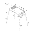
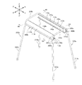
以下、本発明の実施例に係るバーベキューグリルGについて図1A〜図6Bを参照しつつ説明する。バーベキューグリルGは、第1フレーム100aと、第2フレーム100bと、第1支持脚200aと、第2支持脚200bと、第1固定部300aと、第2固定部300bと、第3固定部300cと、第4固定部300dと、第5固定部300eと、第6固定部300fと、第7固定部300gと、第8固定部300hと、火床400と、焼き網500と、鉄板600とを備えている。以下、バーベキューグリルGの各構成要素について詳しく説明する。図1A、図1B、図6A及び図6B中のX−X’方向は、第1、第2フレーム100a、100bの端手方向であって、特許請求の範囲の第1方向に相当している。図1A及び図1B中のY−Y’方向は、第1、第2フレーム100a、100bの長手方向であって、特許請求の範囲の第2方向に相当している。図1A、図1B、図6A及び図6B中のZ−Z’方向は、第1、第2フレーム100a、100bの高さ方向である。Y−Y’方向はX−X’方向に直角に交差しており、Z−Z’方向はY−Y’方向及びX−X’方向に直角に交差している。
Hereinafter, a barbecue grill G according to an embodiment of the present invention will be described with reference to FIGS. 1A to 6B. The barbecue grill G includes a
第1、第2フレーム100a、100bは、図1A〜図6Bに示されるようにアルミ等の金属で構成された筒である。第1、第2フレーム100a、100bはX−X’方向において対称形状である。第1、第2フレーム100a、100bはX−X’方向において互いに間隔をあけて対向している。
The first and
第1フレーム100aは、フレーム本体110aと、第1長尺リブ120aと、第2長尺リブ130aと、第1鍔部140aと、第2鍔部150aとを有している。
The
フレーム本体110aは、Y−Y’方向に延びた略三角形状の筒であって、アルミ等の金属で構成されている。フレーム本体110aは、図6A及び図6Bに最も良く示されているように、底板111aと、外側板112aと、内側板113aと、第1角R1aと、第2角R2aと、第3角R3aとを有している。底板111aは、Y−Y’方向に延びた長方形の板であって、X方向の端と、X’方向の端とを有している。外側板112aは、Y−Y’方向に延びる円弧状の板であって、Z方向及びX’方向に湾曲している。外側板112aは、下端と、上端とを有している。外側板112aの下端が底板111aのX方向の端に一体的に接続されている。内側板113aは、Y−Y’方向に延びる円弧状の板であって、Z方向及びX’方向に湾曲している。内側板113aは、下端と、上端とを有している。内側板113aの下端が底板111aのX’方向の端に一体的に接続されている。外側板112aの上端と内側板113aの上端とが一体的に接続されている。
The frame
第1角R1aは、フレーム本体110aの外側板112aと内側板113aとが突き合わされた角である。第2角R2aは、フレーム本体110aの底板111aと外側板112aとが突き合わされた角である。第3角R3aは、フレーム本体110aの底板111aと内側板113aとが突き合わされた角である。第1角R1a〜R3のY−Y’方向の寸法は、フレーム本体110aのY−Y’方向の寸法と同じである。
The first corner R1a is a corner where the
第1長尺リブ120aは、フレーム本体110aの第1角R1aの内面上に設けられており且つ当該内面のY方向の端からY’方向の端にかけてY−Y’方向に延びている。第1長尺リブ120aのY−Y’方向の寸法は、フレーム本体110aのY−Y’方向の寸法と同じである。第1長尺リブ120aは、X−X’方向の断面において略C字状である。第1長尺リブ120aには、当該第1長尺リブ120aをY−Y’方向に貫通する貫通孔121aが設けられている。
The first
第1長尺リブ120aは、リブ122a(第1リブ)と、リブ123a(第3リブ)とを有している。リブ122aは、第1長尺リブ120aのY方向側の第1端部である。第1長尺リブ120aの貫通孔121aのY方向側の端部の内周面にネジ溝が形成されている。この貫通孔121aのY方向側の端部がリブ122aのネジ孔122a1となっている。ネジ孔122a1もY−Y’方向に延びている。リブ123aは、第1長尺リブ120aのY’方向側の第2端部である。第1長尺リブ120aの貫通孔121aのY’方向側の端部の内周面にネジ溝が形成されている。この貫通孔121aのY’方向側の端部がリブ123aのネジ孔123a1となっている。ネジ孔123a1もY−Y’方向に延びている。
The first
第2長尺リブ130aは、フレーム本体110aの第2角R2aの内面上に設けられており且つ当該内面のY方向の端からY’方向の端にかけてY−Y’方向に延びている。このように第2長尺リブ130aは、フレーム本体110aの内面上の第1長尺リブ120aが設けられた箇所と異なる箇所(第1長尺リブ120aが設けられた箇所よりも下側の箇所)に設けられている。第2長尺リブ130aのY−Y’方向の寸法は、フレーム本体110aのY−Y’方向の寸法と同じである。第2長尺リブ130aは、X−X’方向の断面において略C字状である。第2長尺リブ130aには、当該第2長尺リブ130aをY−Y’方向に貫通する貫通孔131aが設けられている。
The second
第2長尺リブ130aは、リブ132a(第2リブ)と、リブ133a(第4リブ)とを有している。リブ132aは、第2長尺リブ130aのY方向側の第1端部である。第2長尺リブ130aの貫通孔131aのY方向側の端部の内周面にネジ溝が形成されている。この貫通孔131aのY方向側の端部がリブ132aのネジ孔132a1となっている。ネジ孔132a1もY−Y’方向に延びている。リブ133aは、第2長尺リブ130aのY’方向側の第2端部である。第2長尺リブ130aの貫通孔131aのY’方向側の端部の内周面にネジ溝が形成されている。この貫通孔131aのY’方向側の端部がリブ133aのネジ孔133a1となっている。ネジ孔133a1もY−Y’方向に延びている。
The second
第1鍔部140aは、フレーム本体110aの第3角R3aからX’方向(第2フレーム100bの後述するフレーム本体110b側)に延びた後、Z方向に延びた略L字状の板である。第1鍔部140aは、Y−Y’方向に延びた長尺状であって、フレーム本体110aと同じY−Y’方向の寸法を有している。第1鍔部140aの中央部には、Z方向に凸の図示しない突起が設けられている。
The
第2鍔部150aは、フレーム本体110aの内側板113aの第1鍔部140aよりもZ方向側の箇所からX’方向(第2フレーム100bのフレーム本体110b側)に延びた矩形状の板である。第2鍔部150aは、Y−Y’方向に延びた長尺状であって、フレーム本体110aと同じY−Y’方向の寸法を有している。
The
第2フレーム100bは、上記の通り第1フレーム100aの対称形状であるので、第1フレーム100aと相違する部分について詳しく説明し、重複する説明は省略する。第2フレーム100bは、フレーム本体110bと、第1長尺リブ120bと、第2長尺リブ130bと、第1鍔部140bと、第2鍔部150bとを有している。
Since the
フレーム本体110bは、X−X’方向においてフレーム本体110aの対称形状である以外、フレーム本体110aと同じ構成である。フレーム本体110bの外側板112bは、Y−Y’方向に延びる円弧状の板であって、Z方向及びX方向に湾曲している。フレーム本体110bの内側板113bは、Y−Y’方向に延びる円弧状の板であって、Z方向及びX方向に湾曲している。なお、図6A及び図6Bに示される111bは、フレーム本体110bの底板である。R1bはフレーム本体110bの第1角部である。R2bはフレーム本体110bの第2角部である。R3bはフレーム本体110bの第3角部である。
The
第1長尺リブ120bは、X−X’方向において第1長尺リブ120aの対称形状である以外、第1長尺リブ120aと同じ構成である。図6Aに示される122bが第1長尺リブ120bのリブ(第1リブ)であり、122b1がリブ122bのネジ孔である。図6Bに示される123bが第1長尺リブ120bのリブ(第3リブ)であり、123b1がリブ123bのネジ孔である。
The first
第2長尺リブ130bは、X−X’方向において第2長尺リブ130aの対称形状である以外、第2長尺リブ130aと同じ構成である。図6Aに示される132bが第2長尺リブ130bのリブ(第2リブ)であり、132b1がリブ132bのネジ孔である。図6Bに示される133bが第2長尺リブ130bのリブ(第4リブ)であり、133b1がリブ133bのネジ孔である。
The second
第1鍔部140bは、フレーム本体110bの第3角R3bからX方向(第1フレーム100aのフレーム本体110a側)に延びた後、Z方向に延びた略L字状の板である。第2鍔部150bは、フレーム本体110bの内側板113bの第1鍔部140bよりもZ方向側の箇所からX方向(第1フレーム100aのフレーム本体110a側)に延びた矩形状の板である。
The
第1支持脚200aは、図1A〜図5に示されるように下向き略U字状のパイプである。第1支持脚200aは、第1脚部210aと、第2脚部220aと、連結部230aとを有している。
As shown in FIGS. 1A to 5, the
第1脚部210aは、図6Aに最も良く示されているように第1フレーム100aのフレーム本体110aの外側板112aに沿って湾曲した上端部を有するパイプである。第1脚部210aの上端部は、第1フレーム100aのリブ122a及びリブ132aに固定されている。具体的には以下の通りである。第1脚部210aの上端部には、図示しない第1、第2貫通孔が設けられている。第1貫通孔はリブ122aのネジ孔122a1に連通している。第2貫通孔はリブ132aのネジ孔132a1に連通している。ネジである第1固定部300aが第1脚部210aの第1貫通孔に挿入され、第1フレーム100aのリブ122aのネジ孔122a1にネジ止めされている。ネジである第2固定部300bが第1脚部210aの第2貫通孔に挿入され、第1フレーム100aのリブ132aのネジ孔132a1にネジ止めされている。
The
第2脚部220aは、フレーム本体110bの外側板112bに沿って湾曲した上端部を有するパイプである。第2脚部220aの上端部は、第2フレーム100bのリブ122b及びリブ132bに固定されている。具体的には以下の通りである。第2脚部220aの上端部には、図示しない第1、第2貫通孔が設けられている。第1貫通孔はリブ122bのネジ孔122b1に連通している。第2貫通孔はリブ132bのネジ孔132b1に連通している。ネジである第3固定部300cが第2脚部220aの第1貫通孔に挿入され、第2フレーム100bのリブ122bのネジ孔122b1にネジ止めされている。ネジである第4固定部300dが第2脚部220aの第2貫通孔に挿入され、第2フレーム100bのリブ132bのネジ孔132b1にネジ止めされている。
The
連結部230aは、第1脚部210aの上端部と第2脚部220aの上端部とを一体的に連結するパイプである。なお、第1、第2脚部210a、220aは、高さ調整が可能な構成とすることが可能である。例えば、第1、第2脚部210a、220aは、複数のパイプが同心円状に配置され、伸縮可能な構成とすることが可能である。また、第1、第2脚部210a、220aは、複数のパイプを当該パイプの長さ方向に取り外し可能に連結させた構成とすることが可能である。パイプを取り外すことによって、第1、第2脚部210a、220aの高さ調整がなされる。
The connecting
第2支持脚200bは第1支持脚200aと同様の構成であって、第1脚部210bと、第2脚部220bと、連結部230bとを有している。以下、第2支持脚200bが第1支持脚200aと相違する点について詳しく説明し、重複する説明は省略する。
The
第1脚部210bの上端部は、図6Bに最も良く示されているように、第1フレーム100aのリブ123a及びリブ133aに固定されている。具体的には、ネジである第5固定部300eが第1脚部210bの図示しない第1貫通孔に挿入され、第1フレーム100aのリブ123aのネジ孔122a1にネジ止めされている。ネジである第6固定部300fが第1脚部210bの図示しない第2貫通孔に挿入され、第1フレーム100aのリブ133aのネジ孔132a1にネジ止めされている。
The upper end of the
第2脚部220bの上端部は、第2フレーム100bのリブ123b及びリブ133bに固定されている。具体的には、ネジである第7固定部300gが第2脚部220bの図示しない第1貫通孔に挿入され、第2フレーム100bのリブ123bのネジ孔122b1にネジ止めされている。ネジである第8固定部300hが第2脚部220bの図示しない第2貫通孔に挿入され、第2フレーム100bのリブ133bのネジ孔132b1にネジ止めされている。
The upper end portion of the
火床400は、図1Aに示されているように、第1、第2フレーム100a、100bの第1鍔部140a、140bにY−Y’方向に移動自在に懸架されている。火床400は、火床本体410と、フランジ420a、420bとを有している。火床本体410は上方に開放された金属製の箱である。火床本体410に炭や薪などの加熱燃料が収容可能となっている。
As shown in FIG. 1A, the
フランジ420aは、火床本体410からX方向に延びた後、Z’方向に延びた板である。フランジ420aが第1フレーム100aの第1鍔部140aにY−Y’方向に移動自在に支持されている。フランジ420bは、火床本体410からX’方向に延びた後、Z’方向に延びた板である。フランジ420bが第2フレーム100bの第1鍔部140bにY−Y’方向に移動自在に支持されている。フランジ420aのY方向の端部及びフランジ420bのY方向の端部には、図示しない第1ストッパーが各々設けられている。第1ストッパーが第1鍔部140a、140bの突起にY方向側から当接することによって、火床400がY’方向に所定以上移動しないように規制されている。フランジ420aのY’方向の端部及びフランジ420bのY’方向の端部には、図示しない第2ストッパーが各々設けられている。第2ストッパーが第1鍔部140a、140bの突起にY’方向側から当接することによって、火床400がY方向に所定以上移動しないように規制されている。
The
焼き網500は、図1Aに最も良く示されているように金属製の網である。焼き網500及び鉄板600が第1、第2フレーム100a、100bの第2鍔部150a、150bに支持されている。
The
以下、上記した構成のバーベキューグリルGの組み立て手順について詳しく説明する。まず、アルミ等の金属をY−Y’方向に相当する方向に押出成形によって、第1、第2フレーム100a、100bが作成される。その後、第1、第2フレーム100a、100b及び第1支持脚200aを用意する。その後、第1支持脚200aの第1脚部210aの上端部を第1フレーム100aのリブ122a、132aに対向配置させる。このとき、第1脚部210aの第1、第2貫通孔をリブ122a、132aのネジ孔122a1、132a1に連通させる。その後、第1固定部300aを第1貫通孔に挿入し、ネジ孔122a1にネジ止めさせる。第2固定部300bを第2貫通孔に挿入し、ネジ孔132a1にネジ止めさせる。これにより、第1支持脚200aの第1脚部210aが第1フレーム100aのリブ122a、132a(第1、第2長尺リブ120a、130aの第1端部)にネジ止めされる。このようにして第1支持脚200aの第1脚部210aが第1フレーム100aのY方向側の端に固定される。その後、第1支持脚200aの第2脚部220aの上端部を第2フレーム100bのリブ122b、132bに対向配置させる。このとき、第2脚部220aの第1、第2貫通孔をリブ122b、132bのネジ孔122b1、132b1に連通させる。その後、第3固定部300cを第1貫通孔に挿入し、ネジ孔122b1にネジ止めさせる。第4固定部300dを第2貫通孔に挿入し、ネジ孔132b1にネジ止めさせる。これにより、第1支持脚200aの第2脚部220aが第2フレーム100bのリブ122b、132b(第1、第2長尺リブ120b、130bの第1端部)にネジ止めされる。このようにして第1支持脚200aの第2脚部220aが第2フレーム100bのY方向側の端に固定される。
Hereinafter, the assembly procedure of the barbecue grill G having the above-described configuration will be described in detail. First, the first and
その後、第2支持脚200bを用意する。第2支持脚200bの第1脚部210bの上端部を第1フレーム100aのリブ123a、133aに対向配置させる。このとき、第1脚部210bの第1、第2貫通孔をリブ123a、133aのネジ孔123a1、133a1に連通させる。その後、第5固定部300eを第1貫通孔に挿入し、ネジ孔123a1にネジ止めさせる。第6固定部300fを第2貫通孔に挿入し、ネジ孔133a1にネジ止めさせる。これにより、第2支持脚200bの第1脚部210bが第1フレーム100aのリブ123a、133a(第1、第2長尺リブ120a、130aの第2端部)にネジ止めされる。このようにして第2支持脚200bの第1脚部210bが第1フレーム100aのY’方向側の端に固定される。その後、第2支持脚200bの第2脚部220bの上端部を第2フレーム100bのリブ123b、133bに対向配置させる。このとき、第2脚部220bの第1、第2貫通孔をリブ123b、133bのネジ孔123b1、133b1に連通させる。その後、第7固定部300gを第1貫通孔に挿入し、ネジ孔123b1にネジ止めさせる。第8固定部300hを第2貫通孔に挿入し、ネジ孔133b1にネジ止めさせる。これにより、第2支持脚200bの第2脚部220bが第2フレーム100bのリブ123b、133b(第1、第2長尺リブ120b、130bの第2端部)にネジ止めされる。このようにして第2支持脚200bの第2脚部220bが第2フレーム100bのY’方向側の端に固定される。
Then, the
その後、火床400を用意する。火床400のフランジ420a、420bを第1、第2フレーム100a、100bの第1鍔部140a、140b上に載置する。その後、焼き網500及び鉄板600を用意する。焼き網500及び鉄板600を第1、第2フレーム100a、100bの第2鍔部150a、150b上に載置する。
Thereafter, the
以上のようなバーベキューグリルGは、以下の技術的特徴及び効果を有する。第1に、バーベキューグリルGの部品点数の低減を図ることができる。上記の通り、第1支持脚200aの第1、第2脚部210a、220aが第1、第2フレーム100a、100bのY方向側の端に固定され、第2支持脚200bの第1、第2脚部210b、220bが第1、第2フレーム100a、100bのY’方向側の端に固定されている。換言すると、第1、第2支持脚200a、200bが、第1、第2フレーム100a、100bのみで連結されているので、バーベキューグリルGの部品点数の低減を図ることができる。
The barbecue grill G as described above has the following technical features and effects. First, the number of parts of the barbecue grill G can be reduced. As described above, the first and
第2に、第1、第2フレーム100a、100bのみで第1、第2支持脚200a、200bを連結する構成であるにも関わらず、第1、第2フレーム100a、100bに歪みが生じ難い。その理由は以下の通りである。第1、第2フレーム100a、100bのフレーム本体110a、110bが筒で構成されている。フレーム本体110aが、当該フレーム本体110aの第1、第2角R1a、R2aの内面上に設けられ且つY−Y’方向に延びた第1、第2長尺リブ120a、130aによって補強されている。フレーム本体110bが、当該フレーム本体110bの第1、第2角R1b、R2bの内面上に設けられ且つY−Y’方向に延びた第1、第2長尺リブ120b、130bによって補強されている。
Second, although the first and
第3に、第1、第2フレーム100a、100bの断熱効果を向上させることができる。第1、第2フレーム100a、100bのフレーム本体110a、110bが筒で構成されており、フレーム本体110a、110bの内部の空気層によって断熱されるからである。
Third, the heat insulation effect of the first and
第4に、バーベキューグリルGの重量の増加を抑制することができる。上記の通り、第1、第2フレーム100a、100bは、筒であるフレーム本体110aの内面上に第1、第2長尺リブ120a、130aが設けられた構成である。
Fourthly, an increase in the weight of the barbecue grill G can be suppressed. As described above, the first and
なお、本発明のバーベキューグリルは、上記実施例に限定されるものではなく、特許請求の範囲の記載範囲において任意に設計変更することが可能である。以下、詳しく述べる。 In addition, the barbecue grill of this invention is not limited to the said Example, It is possible to change a design arbitrarily in the description range of a claim. Details will be described below.
本発明の第1、第2フレームは第1方向において互いに対向し、且つ上記実施例又は後述する何れかの態様のフレーム本体と、上記実施例又は後述する何れかの態様の第1〜第4リブとを有している限り任意に設計変更することが可能である。 The first and second frames of the present invention are opposed to each other in the first direction, and the frame main body according to any of the above-described embodiments or later described, and the first to fourth embodiments according to any of the above-described embodiments or described later. As long as it has ribs, the design can be changed arbitrarily.
本発明の第1、第2フレームのフレーム本体は、第1方向に交差する第2方向に延びた筒である限り任意に設計変更することが可能である。例えば、フレーム本体は、円筒又は多角形状の筒とすることが可能である。本発明の第1、第2フレームのフレーム本体は、アルミ以外の金属(例えば、スチールやステンレス)又はカーボン等の耐熱性を有する材料で構成することが可能である。 The frame main bodies of the first and second frames of the present invention can be arbitrarily modified as long as they are cylinders extending in the second direction intersecting the first direction. For example, the frame body can be a cylinder or a polygonal cylinder. The frame main bodies of the first and second frames of the present invention can be made of a heat-resistant material such as a metal other than aluminum (for example, steel or stainless steel) or carbon.
本発明の第1、第2フレームの第1リブは、上記した何れかの態様のフレーム本体の第2方向の第1端部の内面又は外面上に設けられている限り任意に設計変更することが可能である。本発明の第1、第2フレームの第2リブは、上記した何れかの態様のフレーム本体の第2方向の第1端部の内面又は外面上に設けられている限り任意に設計変更することが可能である。本発明の第1、第2フレームの第3リブは、上記した何れかの態様のフレーム本体の第1端部の反対側の第2端部の内面又は外面上に設けられている限り任意に設計変更することが可能である。本発明の第1、第2フレームの第4リブは、上記した何れかの態様のフレーム本体の第1端部の反対側の第2端部の内面又は外面上に設けられている限り任意に設計変更することが可能である。 The first ribs of the first and second frames of the present invention may be arbitrarily changed in design as long as they are provided on the inner surface or the outer surface of the first end portion in the second direction of the frame main body according to any one of the aspects described above. Is possible. The design of the second rib of the first and second frames of the present invention is arbitrarily changed as long as it is provided on the inner surface or the outer surface of the first end portion in the second direction of the frame main body according to any one of the aspects described above. Is possible. The 3rd rib of the 1st and 2nd frame of the present invention is arbitrary as long as it is provided on the inner surface or the outer surface of the second end opposite to the first end of the frame main body according to any one of the above aspects. It is possible to change the design. The 4th rib of the 1st and 2nd frame of the present invention is optional as long as it is provided on the inner surface or the outer surface of the second end portion opposite to the first end portion of the frame main body according to any one of the aspects described above. It is possible to change the design.
例えば、本発明の第1、第2フレームの第1、第2長尺リブが省略される場合、本発明の第1、第2フレームの第1リブは、上記した何れかの態様のフレーム本体の第1角の第2方向の第1端部の内面又は外面上に設けられた構成とすることが可能である。本発明の第1、第2フレームの第2リブは、上記した何れかの態様のフレーム本体の第2角の第2方向の第1端部の内面又は外面上に設けられた構成とすることが可能である。本発明の第1、第2フレームの第3リブは、上記した何れかの態様のフレーム本体の第1角の第2方向の第2端部の内面又は外面上に設けられた構成とすることが可能である。本発明の第1、第2フレームの第4リブは、上記した何れかの態様のフレーム本体の第2角の第2方向の第2端部の内面又は外面上に設けられた構成とすることが可能である。本発明の第1、第2フレームの第1、第2リブの少なくとも一方は、上記した何れかの態様のフレーム本体の第1、第2角以外の部分の内面又は外面上の異なる箇所に設けられた構成とすることが可能である。本発明の第1、第2フレームの第3、第4リブの少なくとも一方は、上記した何れかの態様のフレーム本体の第1、第2角以外の部分の内面又は外面上の異なる箇所に設けられた構成とすることが可能である。 For example, when the first and second long ribs of the first and second frames of the present invention are omitted, the first rib of the first and second frames of the present invention is the frame main body according to any one of the above aspects. It is possible to make it the structure provided on the inner surface or outer surface of the 1st edge part of the 1st corner | angular in the 2nd direction. The second ribs of the first and second frames of the present invention are configured to be provided on the inner surface or the outer surface of the first end portion in the second direction of the second corner of the frame body according to any one of the aspects described above. Is possible. The third ribs of the first and second frames of the present invention are configured to be provided on the inner surface or the outer surface of the second end portion in the second direction of the first corner of the frame body according to any one of the aspects described above. Is possible. The fourth ribs of the first and second frames of the present invention are configured to be provided on the inner surface or the outer surface of the second end portion in the second direction of the second corner of the frame main body according to any one of the aspects described above. Is possible. At least one of the first and second ribs of the first and second frames of the present invention is provided at different locations on the inner surface or the outer surface of the portion other than the first and second corners of the frame main body according to any of the above-described aspects. It is possible to have a configured configuration. At least one of the third and fourth ribs of the first and second frames of the present invention is provided at different locations on the inner surface or the outer surface of the portion other than the first and second corners of the frame main body according to any one of the aspects described above. It is possible to have a configured configuration.
本発明の第1、第2フレームの第1、第2長尺リブは、上記した何れかの態様のフレーム本体の内面又は外面上に設けられており且つ当該内面又は外面の前記第2方向の一端から他端にかけて前記第2方向に延びていると良い。第1長尺リブは、上記した何れかの態様のフレーム本体の第1角の内面又は外面上に設けられても良い。第2長尺リブは、上記した何れかの態様のフレーム本体の第2角の内面又は外面上に設けられていても良い。上記した何れかの態様の第1長尺リブの第2方向の第1端部が第1リブに相当し、当該第1長尺リブの第1端部の反対側の第2端部が第3リブに相当すると良い。上記した何れかの態様の第2長尺リブの第2方向の第1端部が第2リブに相当し、当該第2長尺リブの第1端部の反対側の第2端部が第4リブに相当すると良い。本発明の第1、第2フレームの第1、第2長尺リブの少なくとも一方は、上記した何れかの態様のフレーム本体の第1、第2角以外の部分の内面又は外面上に設けられた構成とすることが可能である。本発明の第1、第2長尺リブは、第1方向の断面において略O字状(すなわち、筒状)とすることが可能である。また、第1、第2長尺リブには、貫通孔が設けられていない構成とすることが可能である。この場合、第1長尺リブの第1、第3リブ、及び第2長尺リブの第2、第4リブにのみ、ネジ孔又は係合孔が設けられた構成とすることが可能である。なお、上記した何れかの態様の第1、第2長尺リブは一体化することが可能である。 The first and second long ribs of the first and second frames of the present invention are provided on the inner surface or the outer surface of the frame main body according to any one of the aspects described above, and the inner surface or the outer surface in the second direction. It is good to extend in the said 2nd direction from one end to the other end. The first long rib may be provided on the inner surface or the outer surface of the first corner of the frame main body according to any one of the aspects described above. The second long rib may be provided on the inner surface or the outer surface of the second corner of the frame main body according to any one of the aspects described above. The first end in the second direction of the first long rib of any one of the above aspects corresponds to the first rib, and the second end opposite to the first end of the first long rib is the first end. It should be equivalent to 3 ribs. The first end portion in the second direction of the second long rib in any one of the above aspects corresponds to the second rib, and the second end portion on the opposite side of the first end portion of the second long rib is the first end portion. It should be equivalent to 4 ribs. At least one of the first and second long ribs of the first and second frames of the present invention is provided on the inner surface or the outer surface of the portion other than the first and second corners of the frame main body according to any one of the aspects described above. Can be configured. The first and second long ribs of the present invention can be substantially O-shaped (that is, cylindrical) in the cross section in the first direction. Further, the first and second long ribs may be configured such that no through hole is provided. In this case, it is possible to adopt a configuration in which screw holes or engagement holes are provided only in the first and third ribs of the first long rib and the second and fourth ribs of the second long rib. . In addition, the 1st, 2nd elongate rib of either aspect mentioned above can be integrated.
本発明の第1、第2フレームは、第1、第2長尺リブの代りに、第3、第4長尺リブを有する構成とすることが可能である。第3長尺リブは、第1、第2フレームのフレーム本体の第1端部の内面又は外面上に設けられており且つ当該フレーム本体の周方向に延びていると良い。第4長尺リブは、第1、第2フレームのフレーム本体の第2端部の内面又は外面上に設けられており且つ当該フレーム本体の周方向に延びていると良い。第1リブは第3長尺リブの長さ方向の第1端部である。第2リブは第3長尺リブの第1端部の反対側の第2端部である。第3リブは第4長尺リブの長さ方向の第1端部である。第4リブは第4長尺リブの第1端部の反対側の第2端部である。 The 1st, 2nd frame of this invention can be set as the structure which has a 3rd, 4th elongate rib instead of a 1st, 2nd elongate rib. The third long rib is preferably provided on the inner surface or the outer surface of the first end of the frame body of the first and second frames and extends in the circumferential direction of the frame body. The fourth long rib may be provided on the inner surface or the outer surface of the second end portion of the frame main body of the first and second frames and may extend in the circumferential direction of the frame main body. The first rib is a first end portion in the length direction of the third long rib. The second rib is a second end portion opposite to the first end portion of the third long rib. The third rib is a first end portion in the length direction of the fourth long rib. The fourth rib is a second end portion opposite to the first end portion of the fourth long rib.
この一例が図7A及び図7Bに示されている。図7A中の161aが第1フレーム100a’のフレーム本体110aの第1端部の内面上に設けられた第3長尺リブであり、161bが第2フレーム100b’のフレーム本体110bの第1端部の内面上に設けられた第3長尺リブである。第1リブ122a’は第3長尺リブ161aの長さ方向の第1端部である。第2リブ132a’は第3長尺リブ161aの第1端部の反対側の第2端部である。122a1’は第1リブ122a’のネジ孔であり、132a1’は第2リブ132a’のネジ孔である。第1リブ122b’は第3長尺リブ161bの長さ方向の第1端部である。第2リブ132b’は第3長尺リブ161bの第1端部の反対側の第2端部である。122b1’は第1リブ122b’のネジ孔であり、132b1’は第2リブ132b’のネジ孔である。図7B中の162aが第1フレーム100a’のフレーム本体110aの第2端部の内面上に設けられた第4長尺リブであり、162bが第2フレーム100b’のフレーム本体110bの第2端部の内面上に設けられた第4長尺リブである。第3リブ123a’は第4長尺リブ162aの長さ方向の第1端部である。第4リブ133a’は第4長尺リブ162aの第1端部の反対側の第2端部である。123a1’は第3リブ123a’のネジ孔であり、133a1’は第4リブ133a’のネジ孔である。第3リブ123b’は第4長尺リブ162bの長さ方向の第1端部である。第4リブ133b’は第4長尺リブ162bの第1端部の反対側の第2端部である。123b1’は第3リブ123b’のネジ孔であり、133b1’は第4リブ133b’のネジ孔である。
An example of this is shown in FIGS. 7A and 7B. In FIG. 7A, 161a is a third long rib provided on the inner surface of the first end of the
なお、上記した何れかの態様の第1リブは、フレーム本体の内面及び外面の何れか一方上に設けられ、上記した何れかの態様の第2リブがフレーム本体の内面及び外面の他方上に設けられた構成とすることが可能である。上記した何れかの態様の第3リブは、フレーム本体の内面及び外面の何れか一方上に設けられ、上記した何れかの態様の第4リブがフレーム本体の内面及び外面の他方上に設けられた構成とすることが可能である。上記第1〜第4リブは、フレーム本体に溶接などで固定されていても良い。上記第3、第4長尺リブも、フレーム本体に溶接などで固定されていても良い。 The first rib of any one of the aspects described above is provided on either the inner surface or the outer surface of the frame body, and the second rib of any one of the aspects described above is provided on the other of the inner surface or the outer surface of the frame body. It is possible to have a provided configuration. The third rib of any one of the above aspects is provided on one of the inner surface and the outer surface of the frame body, and the fourth rib of any of the above aspects is provided on the other of the inner surface and the outer surface of the frame body. Can be configured. The first to fourth ribs may be fixed to the frame body by welding or the like. The third and fourth long ribs may also be fixed to the frame body by welding or the like.
本発明の第1支持脚は、上記した何れかの態様の第1フレームの第1リブ及び第2リブに固定された第1脚部と、上記した何れかの態様の第2フレームの第1リブ及び第2リブに固定された第2脚部と、第1支持脚の第1脚部と第2脚部とを連結する連結部とを有している限り任意に設計変更することが可能である。例えば、第1支持脚の第1脚部が上記した何れかの態様の第1フレームの第1リブ、第2リブにピン止めされる構成とすることが可能である。具体的には、ピンである第1、第2固定部が第1支持脚の第1脚部を貫通して第1フレームの第1、第2リブの係合孔に係合される構成とすることが可能である。同様に、第1支持脚の第2脚部が上記した何れかの態様の第2フレームの第1、第2リブにピン止めされる構成とすることが可能である。具体的には、ピンである第3、第4固定部が第1支持脚の第2脚部を貫通して第2フレームの第1、第2リブの係合孔に係合される構成とすることが可能である。なお、上記した何れかの態様の第1支持脚の第1脚部は、第1、第2リブに加えて、第1フレームの第1端部の内面又は外面上に設けられた一又は複数のリブに固定されていても良い。上記した何れかの態様の第1支持脚の第2脚部は、第1、第2リブに加えて、第2フレームの第1端部の内面又は外面上に設けられた一又は複数のリブに固定されていても良い。 The first support leg of the present invention includes a first leg portion fixed to the first rib and the second rib of the first frame according to any one of the aspects described above, and the first frame of the second frame according to any aspect described above. The design can be arbitrarily changed as long as it has the second leg portion fixed to the rib and the second rib and the connecting portion for connecting the first leg portion and the second leg portion of the first support leg. It is. For example, the first leg portion of the first support leg can be configured to be pinned to the first rib and the second rib of the first frame in any of the above-described aspects. Specifically, the first and second fixing portions, which are pins, pass through the first leg portions of the first support legs and are engaged with the engagement holes of the first and second ribs of the first frame. Is possible. Similarly, the second leg portion of the first support leg can be configured to be pinned to the first and second ribs of the second frame in any of the above-described aspects. Specifically, the third and fourth fixing portions, which are pins, pass through the second leg portion of the first support leg and are engaged with the engagement holes of the first and second ribs of the second frame. Is possible. In addition, the 1st leg part of the 1st support leg of any one of the above-mentioned aspects is provided with one or more provided on the inner surface or the outer surface of the first end of the first frame in addition to the first and second ribs. It may be fixed to the rib. In addition to the first and second ribs, the second leg of the first support leg according to any one of the aspects described above is one or a plurality of ribs provided on the inner surface or the outer surface of the first end of the second frame. It may be fixed to.
本発明の第1支持脚の連結部は、上記した何れかの態様の第1支持脚の第1脚部と第2脚部とを連結するものであれば良い。例えば、連結部は、第1支持脚の第1脚部と第2脚部とを連結する第1、第2脚部と別体のパイプや板等であっても良い。 The connection part of the 1st support leg of this invention should just connect the 1st leg part and 2nd leg part of the 1st support leg of any aspect mentioned above. For example, the connecting portion may be a pipe or plate that is separate from the first and second leg portions that connect the first leg portion and the second leg portion of the first support leg.
本発明の第2支持脚は、上記した何れかの態様の第1フレームの第3リブ及び第4リブに固定された第1脚部と、上記した何れかの態様の第2フレームの第3リブ及び第4リブに固定された第2脚部と、第2支持脚の第1脚部と第2脚部とを連結する連結部とを有している限り任意に設計変更することが可能である。例えば、第2支持脚の第1脚部が上記した何れかの態様の第1フレームの第3、第4リブにピン止めされる構成とすることが可能である。具体的には、ピンである第5、第6固定部が第2支持脚の第1脚部を貫通して第1フレームの第3、第4リブの係合孔に係合される構成とすることが可能である。同様に、第2支持脚の第2脚部が上記した何れかの態様の第2フレームの第3、第4リブにピン止めされる構成とすることが可能である。具体的には、ピンである第7、第8固定部が第2支持脚の第2脚部を貫通して第2フレームの第3、第4リブの係合孔に係合される構成とすることが可能である。なお、上記した何れかの態様の第2支持脚の第1脚部は、第3、第4リブに加えて、第1フレームの第2端部の内面又は外面上に設けられた一又は複数のリブに固定されていても良い。上記した何れかの態様の第2支持脚の第2脚部は、第3、第4リブに加えて、第2フレームの第2端部の内面又は外面上に設けられた一又は複数のリブに固定されていても良い。 The second support leg of the present invention includes a first leg portion fixed to the third rib and the fourth rib of the first frame according to any of the aspects described above, and a third frame of the second frame according to any of the aspects described above. The design can be arbitrarily changed as long as it has the second leg portion fixed to the rib and the fourth rib and the connecting portion for connecting the first leg portion and the second leg portion of the second support leg. It is. For example, the first leg portion of the second support leg may be configured to be pinned to the third and fourth ribs of the first frame in any of the above-described aspects. Specifically, the fifth and sixth fixing portions, which are pins, pass through the first leg portion of the second support leg and are engaged with the engagement holes of the third and fourth ribs of the first frame. Is possible. Similarly, the second leg portion of the second support leg can be configured to be pinned to the third and fourth ribs of the second frame in any of the above-described aspects. Specifically, the seventh and eighth fixing portions, which are pins, pass through the second leg portion of the second support leg and are engaged with the engagement holes of the third and fourth ribs of the second frame; Is possible. In addition, the 1st leg part of the 2nd support leg of any one of the above-mentioned aspects is one or more provided on the inner surface or the outer surface of the second end of the first frame in addition to the third and fourth ribs. It may be fixed to the rib. In addition to the third and fourth ribs, the second leg portion of the second support leg according to any one of the aspects described above is one or a plurality of ribs provided on the inner surface or the outer surface of the second end portion of the second frame. It may be fixed to.
本発明の第2支持脚の連結部は、上記した何れかの態様の第2支持脚の第1脚部と第2脚部とを連結するものであれば良い。例えば、連結部は、第2支持脚の第1脚部と第2脚部とを連結する第1、第2脚部と別体のパイプや板等であっても良い。 The connection part of the 2nd support leg of this invention should just connect the 1st leg part and 2nd leg part of the 2nd support leg of any aspect mentioned above. For example, the connecting portion may be a pipe, a plate, or the like that is separate from the first and second leg portions that connect the first leg portion and the second leg portion of the second support leg.
本発明の第1固定部は、上記した何れかの態様の第1支持脚の第1脚部を上記した何れかの態様の第1フレームの第1リブに固定し得る限り任意に設計変更することが可能である。本発明の第2固定部は、上記した何れかの態様の第1支持脚の第1脚部を上記した何れかの態様の第1フレームの第2リブに固定し得る限り任意に設計変更することが可能である。上記した何れかの態様の第1、第2固定部は、第1脚部に一体化させることが可能である。 The design of the first fixing portion of the present invention is arbitrarily changed as long as the first leg portion of the first support leg of any aspect described above can be fixed to the first rib of the first frame of any aspect described above. It is possible. The design of the second fixing portion of the present invention is arbitrarily changed as long as the first leg portion of the first support leg of any aspect described above can be fixed to the second rib of the first frame of any aspect described above. It is possible. The 1st, 2nd fixing | fixed part of any aspect mentioned above can be integrated with a 1st leg part.
本発明の第3固定部は、上記した何れかの態様の第1支持脚の第2脚部を上記した何れかの態様の第2フレームの第1リブに固定し得る限り任意に設計変更することが可能である。本発明の第4固定部は、上記した何れかの態様の第1支持脚の第2脚部を上記した何れかの態様の第2フレームの第2リブに固定し得る限り任意に設計変更することが可能である。上記した何れかの態様の第3、第4固定部は、第2脚部に一体化させることが可能である。 The third fixing portion of the present invention is arbitrarily changed in design as long as the second leg portion of the first support leg of any aspect described above can be fixed to the first rib of the second frame of any aspect described above. It is possible. The fourth fixing portion of the present invention is arbitrarily changed in design as long as the second leg portion of the first support leg of any aspect described above can be fixed to the second rib of the second frame of any aspect described above. It is possible. The 3rd, 4th fixing | fixed part of either aspect mentioned above can be integrated with a 2nd leg part.
本発明の第5固定部は、上記した何れかの態様の第2支持脚の第1脚部を上記した何れかの態様の第1フレームの第3リブに固定し得る限り任意に設計変更することが可能である。本発明の第6固定部は、上記した何れかの態様の第2支持脚の第1脚部を上記した何れかの態様の第1フレームの第4リブに固定し得る限り任意に設計変更することが可能である。上記した何れかの態様の第5、第6固定部は、第1脚部に一体化させることが可能である。 The fifth fixing portion of the present invention is arbitrarily changed in design as long as the first leg portion of the second support leg of any aspect described above can be fixed to the third rib of the first frame of any aspect described above. It is possible. The sixth fixing portion of the present invention is arbitrarily changed in design as long as the first leg portion of the second support leg of any aspect described above can be fixed to the fourth rib of the first frame of any aspect described above. It is possible. The fifth and sixth fixing portions in any one of the above aspects can be integrated with the first leg portion.
本発明の第7固定部は、上記した何れかの態様の第2支持脚の第2脚部を上記した何れかの態様の第2フレームの第3リブに固定し得る限り任意に設計変更することが可能である。本発明の第8固定部は、上記した何れかの態様の第2支持脚の第2脚部を上記した何れかの態様の第2フレームの第4リブに固定し得る限り任意に設計変更することが可能である。上記した何れかの態様の第7、第8固定部は、第2脚部に一体化させることが可能である。 The design of the seventh fixing portion of the present invention is arbitrarily changed as long as the second leg portion of the second support leg of any aspect described above can be fixed to the third rib of the second frame of any aspect described above. It is possible. The eighth fixing portion of the present invention is arbitrarily changed in design as long as the second leg portion of the second support leg of any aspect described above can be fixed to the fourth rib of the second frame of any aspect described above. It is possible. The seventh and eighth fixing portions of any one of the above aspects can be integrated with the second leg portion.
本発明の火床は、上記した何れかの態様の第1、第2フレーム及び第1、第2支持脚の少なくとも一方に支持される構成である限り任意に設計変更することが可能である。例えば、火床は、上記した第1、第2支持脚の連結部に係合可能なフックを有する構成とすることが可能である。この場合、第1、第2フレームの第1鍔部は省略可能である。なお、第1、第2フレームの第1鍔部は、火床が懸架され得るものである限り任意に設計変更することが可能である。 The design of the fire bed of the present invention can be arbitrarily changed as long as it is configured to be supported by at least one of the first and second frames and the first and second support legs in any of the above-described aspects. For example, the fire bed can be configured to have hooks that can be engaged with the connecting portions of the first and second support legs. In this case, the first collar portion of the first and second frames can be omitted. The design of the first brim part of the first and second frames can be arbitrarily changed as long as the fire bed can be suspended.
本発明のバーベキューグリルは、上記した何れかの態様の第1、第2フレーム及び第1、第2支持脚の少なくとも一方に支持される焼き網及び鉄板の少なくとも一方を備えた構成とすることが可能である。焼き網及び/又は鉄板が第1、第2支持脚に支持される場合、第1、第2フレームの第2鍔部は省略可能である。 The barbecue grill of the present invention is configured to include at least one of a grill and an iron plate supported by at least one of the first and second frames and the first and second support legs of any of the above-described aspects. Is possible. When the grill net and / or the iron plate are supported by the first and second support legs, the second flange portions of the first and second frames can be omitted.
なお、上記実施例及び設計変形例におけるバーベキューグリルの各構成要素を構成する素材、形状、寸法、数及び配置等はその一例を説明したものであって、同様の機能を実現し得る限り任意に設計変更することが可能である。上記した実施例及び設計変更例は、互いに矛盾しない限り、相互に組み合わせることが可能である。上記した何れかの態様の第1、第2支持脚は、上記した何れかの態様の第1、第2フレームのみで連結されるものに限定されない。すなわち、本発明は、第1、第2支持脚が、第1、第2フレームに加えて、別の部材で連結されるバーベキューグリルに対しても適応可能である。本発明の第1方向は、第1、第2フレームが対向する方向である限り任意に設定することが可能である。本発明の第2方向は、第1、第2フレームの長手方向であり且つ第1方向に交差する方向である限り任意に設定可能である。 The material, shape, dimensions, number, arrangement, etc. constituting each component of the barbecue grill in the above embodiment and design modification are examples, and are arbitrary as long as the same function can be realized. It is possible to change the design. The above-described embodiments and design modification examples can be combined with each other as long as they do not contradict each other. The first and second support legs in any one of the above-described aspects are not limited to those connected only by the first and second frames in any one of the above-described aspects. That is, the present invention can be applied to a barbecue grill in which the first and second support legs are connected by another member in addition to the first and second frames. The first direction of the present invention can be arbitrarily set as long as the first and second frames face each other. The second direction of the present invention can be arbitrarily set as long as it is the longitudinal direction of the first and second frames and the direction intersecting the first direction.
G・・・・・・・・バーベキューグリル
100a・・・・第1フレーム
110a・・・フレーム本体
111a・・底板
112a・・外側板
113a・・内側板
R1a・・・第1角
R2a・・・第2角
R3a・・・第3角
120a・・・第1長尺リブ
121a・・貫通孔
122a・・リブ(第1リブ)
122a1・ネジ孔
123a・・リブ(第3リブ)
123a1・ネジ孔
130a・・・第2長尺リブ
131a・・貫通孔
132a・・リブ(第2リブ)
132a1・ネジ孔
133a・・リブ(第4リブ)
133a1・ネジ孔
100b・・・・第2フレーム
110b・・・フレーム本体
111b・・底板
112b・・外側板
113b・・内側板
R1b・・・第1角
R2b・・・第2角
R3b・・・第3角
120b・・・第1長尺リブ
121b・・貫通孔
122b・・リブ(第1リブ)
122b1・ネジ孔
123b・・リブ(第3リブ)
123b1・ネジ孔
130b・・・第2長尺リブ
131b・・貫通孔
132b・・リブ(第2リブ)
132b1・ネジ孔
133b・・リブ(第4リブ)
133b1・ネジ孔
140a・・・第1鍔部
140b・・・第1鍔部
150a・・・第2鍔部
150b・・・第2鍔部
200a・・・・第1支持脚
210a・・・第1脚部
220a・・・第2脚部
230a・・・連結部
200b・・・・第2支持脚
210b・・・第1脚部
220b・・・第2脚部
230b・・・連結部
300a〜300h・第1〜第8固定部
400・・・・・火床
410・・・・火床本体
420a・・・フランジ
420b・・・フランジ
500・・・・・焼き網
G ...
122a1,
123a1,
132a1 ・
133a1 ·
122b1,
123b1,
132b1 ·
133b1 · screw
Claims (11)
第1、第2支持脚とを備えており、
前記第1、第2フレームは、前記第1方向に交差する第2方向に延びた筒であって、前記第2方向の第1端部および前記第1端部の反対側の第2端部を有し、且つ前記第1端部が前記第2方向の一方に開放され、前記第2端部が前記第2方向の他方に開放されたフレーム本体と、
前記フレーム本体の前記第1端部の内面又は外面上に設けられた第1リブと、
前記フレーム本体の前記第1端部の内面又は外面上に設けられた第2リブと、
前記フレーム本体の前記第2端部の内面又は外面上に設けられた第3リブと、
前記フレーム本体の前記第2端部の内面又は外面上に設けられた第4リブとを有しており、
前記第1支持脚は、前記第1フレームの前記第1リブ及び前記第2リブに固定された第1脚部と、
前記第2フレームの前記第1リブ及び前記第2リブに固定された第2脚部と、
前記第1脚部と前記第2脚部とを連結する連結部とを有しており、
前記第2支持脚は、前記第1フレームの前記第3リブ及び前記第4リブに固定された第1脚部と、
前記第2フレームの前記第3リブ及び前記第4リブに固定された第2脚部と、
当該第2支持脚の前記第1脚部と前記第2脚部とを連結する連結部とを有しているバーベキューグリル。 First and second frames facing each other at an interval in a first direction;
First and second support legs,
The first and second frames are cylinders extending in a second direction intersecting the first direction, and a first end in the second direction and a second end opposite to the first end. A frame main body having the first end opened to one side in the second direction and the second end opened to the other in the second direction ;
A first rib provided on the inner or outer surface of the first end of the frame body,
A second rib provided on the inner or outer surface of the first end portion of said frame body,
A third rib provided on the inner or outer surface of the second end of the frame body,
And a fourth rib provided on the inner or outer surface of the second end of the frame body,
The first support leg includes a first leg portion fixed to the first rib and the second rib of the first frame;
A second leg fixed to the first rib and the second rib of the second frame;
A connecting portion that connects the first leg portion and the second leg portion;
The second support leg includes a first leg portion fixed to the third rib and the fourth rib of the first frame;
A second leg fixed to the third rib and the fourth rib of the second frame;
A barbecue grill having a connection portion for connecting the first leg portion and the second leg portion of the second support leg.
第1、第2支持脚とを備えており、
前記第1、第2フレームは、前記第1方向に交差する第2方向に延びた多角形状の筒であって、第1、第2角を更に有するフレーム本体と、
前記フレーム本体の前記第1角の前記第2方向の第1端部の内面又は外面上に設けられた第1リブと、
前記フレーム本体の前記第2角の前記第2方向の第1端部の内面又は外面上に設けられた第2リブと、
前記フレーム本体の前記第1角の前記第1端部の反対側の第2端部の内面又は外面上に設けられた第3リブと、
前記フレーム本体の前記第2角の前記第1端部の反対側の第2端部の内面又は外面上に設けられた第4リブとを有しており、
前記第1支持脚は、前記第1フレームの前記第1リブ及び前記第2リブに固定された第1脚部と、
前記第2フレームの前記第1リブ及び前記第2リブに固定された第2脚部と、
前記第1脚部と前記第2脚部とを連結する連結部とを有しており、
前記第2支持脚は、前記第1フレームの前記第3リブ及び前記第4リブに固定された第1脚部と、
前記第2フレームの前記第3リブ及び前記第4リブに固定された第2脚部と、
当該第2支持脚の前記第1脚部と前記第2脚部とを連結する連結部とを有しているバーベキューグリル。 First and second frames facing each other at an interval in a first direction;
First and second support legs,
The first and second frames are polygonal cylinders extending in a second direction intersecting the first direction, and a frame body further having first and second corners;
A first rib provided on an inner surface or an outer surface of the first end portion in the second direction of the first corner of the frame body;
A second rib provided on an inner surface or an outer surface of the first end portion in the second direction of the second corner of the frame body;
A third rib provided on the inner surface or the outer surface of the second end opposite to the first end of the first corner of the frame body;
A fourth rib provided on the inner surface or the outer surface of the second end opposite to the first end of the second corner of the frame body,
The first support leg includes a first leg portion fixed to the first rib and the second rib of the first frame;
A second leg fixed to the first rib and the second rib of the second frame;
A connecting portion that connects the first leg portion and the second leg portion;
The second support leg includes a first leg portion fixed to the third rib and the fourth rib of the first frame;
A second leg fixed to the third rib and the fourth rib of the second frame;
A barbecue grill having a connection portion for connecting the first leg portion and the second leg portion of the second support leg .
第1、第2支持脚とを備えており、
前記第1、第2フレームは、前記第1方向に交差する第2方向に延びた筒であるフレーム本体と、
第1、第2長尺リブとを有しており、
前記第1長尺リブは、前記第1、第2フレームの前記フレーム本体の内面又は外面上に設けられており且つ当該内面又は外面の前記第2方向の一端から他端にかけて前記第2方向に延びており、且つ前記第1長尺リブの前記第2方向の第1端部である第1リブと前記第1長尺リブの前記第1端部の反対側の第2端部である第3リブとを有しており、
前記第2長尺リブは、前記第1、第2フレームの前記フレーム本体の内面又は外面上に設けられており且つ当該内面又は外面の前記第2方向の一端から他端にかけて前記第2方向に延びており、且つ前記第2長尺リブの前記第2方向の第1端部である第2リブと前記第2長尺リブの前記第1端部の反対側の第2端部である第4リブとを有しており、
前記第1支持脚は、前記第1フレームの前記第1リブ及び前記第2リブに固定された第1脚部と、
前記第2フレームの前記第1リブ及び前記第2リブに固定された第2脚部と、
前記第1脚部と前記第2脚部とを連結する連結部とを有しており、
前記第2支持脚は、前記第1フレームの前記第3リブ及び前記第4リブに固定された第1脚部と、
前記第2フレームの前記第3リブ及び前記第4リブに固定された第2脚部と、
当該第2支持脚の前記第1脚部と前記第2脚部とを連結する連結部とを有しているバーベキューグリル。 First and second frames facing each other at an interval in a first direction;
First and second support legs,
The first and second frames are frame bodies that are cylinders extending in a second direction intersecting the first direction;
Having first and second elongated ribs,
The first long rib is provided on an inner surface or an outer surface of the frame main body of the first and second frames, and extends from one end to the other end of the inner surface or the outer surface in the second direction. A first rib that extends and is a first end that is a first end in the second direction of the first long rib and a second end that is opposite to the first end of the first long rib. 3 ribs,
The second long rib is provided on the inner surface or the outer surface of the frame main body of the first and second frames, and extends in the second direction from one end to the other end of the inner surface or the outer surface in the second direction. A second rib that extends and is a second end opposite to the first end of the second long rib and a second rib that is the first end of the second long rib in the second direction. 4 ribs,
The first support leg includes a first leg portion fixed to the first rib and the second rib of the first frame;
A second leg fixed to the first rib and the second rib of the second frame;
A connecting portion that connects the first leg portion and the second leg portion;
The second support leg includes a first leg portion fixed to the third rib and the fourth rib of the first frame;
A second leg fixed to the third rib and the fourth rib of the second frame;
A barbecue grill having a connection portion for connecting the first leg portion and the second leg portion of the second support leg .
前記フレーム本体は、多角形状の筒であって、第1、第2角を更に有しており、
前記第1長尺リブが前記フレーム本体の前記第1角の内面又は外面上に設けられており、
前記第2長尺リブが前記フレーム本体の前記第2角の内面又は外面上に設けられているバーベキューグリル。 The barbecue grill according to claim 3,
The frame body is a polygonal cylinder and further includes first and second corners;
The first long rib is provided on an inner surface or an outer surface of the first corner of the frame body;
A barbecue grill in which the second long rib is provided on an inner surface or an outer surface of the second corner of the frame body.
第1、第2支持脚とを備えており、
前記第1、第2フレームは、前記第1方向に交差する第2方向に延びた筒であるフレーム本体と、
第3、第4長尺リブとを有しており、
前記第3長尺リブは、前記第1、第2フレームの前記フレーム本体の前記第1端部の内面又は外面上に設けられており且つ当該フレーム本体の周方向に延びており、且つ前記第3長尺リブの長さ方向の第1端部である第1リブと前記第3長尺リブの前記第1端部の反対側の第2端部である第2リブとを有しており、
前記第4長尺リブは、前記第1、第2フレームの前記フレーム本体の前記第2端部の内面又は外面上に設けられており且つ当該フレーム本体の周方向に延びており、且つ前記第4長尺リブの長さ方向の第1端部である第3リブと前記第4長尺リブの前記第1端部の反対側の第2端部である第4リブとを有しており、
前記第1支持脚は、前記第1フレームの前記第1リブ及び前記第2リブに固定された第1脚部と、
前記第2フレームの前記第1リブ及び前記第2リブに固定された第2脚部と、
前記第1脚部と前記第2脚部とを連結する連結部とを有しており、
前記第2支持脚は、前記第1フレームの前記第3リブ及び前記第4リブに固定された第1脚部と、
前記第2フレームの前記第3リブ及び前記第4リブに固定された第2脚部と、
当該第2支持脚の前記第1脚部と前記第2脚部とを連結する連結部とを有しているバーベキューグリル。 First and second frames facing each other at an interval in a first direction;
First and second support legs,
The first and second frames are frame bodies that are cylinders extending in a second direction intersecting the first direction;
Having third and fourth elongated ribs,
The third long rib is provided on an inner surface or an outer surface of the first end of the frame body of the first and second frames , extends in a circumferential direction of the frame body, and A first rib that is a first end in the length direction of the three long ribs, and a second rib that is a second end opposite to the first end of the third long rib. ,
The fourth long rib is provided on an inner surface or an outer surface of the second end portion of the frame body of the first and second frames , extends in a circumferential direction of the frame body, and A third rib that is a first end in the length direction of the four long ribs, and a fourth rib that is a second end opposite to the first end of the fourth long rib. ,
The first support leg includes a first leg portion fixed to the first rib and the second rib of the first frame;
A second leg fixed to the first rib and the second rib of the second frame;
A connecting portion that connects the first leg portion and the second leg portion;
The second support leg includes a first leg portion fixed to the third rib and the fourth rib of the first frame;
A second leg fixed to the third rib and the fourth rib of the second frame;
A barbecue grill having a connection portion for connecting the first leg portion and the second leg portion of the second support leg .
前記第1〜第4リブは、前記第2方向に延びるネジ孔を有しており、
前記バーベキューグリルは、前記第1支持脚の前記第1脚部を貫通して前記第1フレームの前記第1リブのネジ孔にネジ止めされたネジである第1固定部と、
前記第1支持脚の前記第1脚部を貫通して前記第1フレームの前記第2リブのネジ孔にネジ止めされたネジである第2固定部と、
前記第1支持脚の前記第2脚部を貫通して前記第2フレームの前記第1リブのネジ孔にネジ止めされたネジである第3固定部と、
前記第1支持脚の前記第2脚部を貫通して前記第2フレームの前記第2リブのネジ孔にネジ止めされたネジである第4固定部と、
前記第2支持脚の前記第1脚部を貫通して前記第1フレームの前記第3リブのネジ孔にネジ止めされたネジである第5固定部と、
前記第2支持脚の前記第1脚部を貫通して前記第1フレームの前記第4リブのネジ孔にネジ止めされたネジである第6固定部と、
前記第2支持脚の前記第2脚部を貫通して前記第2フレームの前記第3リブのネジ孔にネジ止めされたネジである第7固定部と、
前記第2支持脚の前記第2脚部を貫通して前記第2フレームの前記第4リブのネジ孔にネジ止めされたネジである第8固定部とを更に備えているバーベキューグリル。 In the barbecue grill in any one of Claims 1-5,
The first to fourth ribs have screw holes extending in the second direction,
The barbecue grill has a first fixing portion that is a screw that passes through the first leg portion of the first support leg and is screwed into a screw hole of the first rib of the first frame;
A second fixing portion that is a screw that passes through the first leg portion of the first support leg and is screwed into a screw hole of the second rib of the first frame;
A third fixing portion that is a screw that passes through the second leg portion of the first support leg and is screwed into a screw hole of the first rib of the second frame;
A fourth fixing portion that is a screw that passes through the second leg portion of the first support leg and is screwed into a screw hole of the second rib of the second frame;
A fifth fixing portion that is a screw that passes through the first leg portion of the second support leg and is screwed into a screw hole of the third rib of the first frame;
A sixth fixing portion that is a screw that passes through the first leg portion of the second support leg and is screwed into a screw hole of the fourth rib of the first frame;
A seventh fixing portion that is a screw that passes through the second leg portion of the second support leg and is screwed into a screw hole of the third rib of the second frame;
The barbecue grill further comprising an eighth fixing portion that is a screw that passes through the second leg portion of the second support leg and is screwed into a screw hole of the fourth rib of the second frame.
前記第1〜第4リブは、前記第2方向に延びる係合孔を有しており、
前記バーベキューグリルは、前記第1支持脚の前記第1脚部を貫通して前記第1フレームの前記第1リブの係合孔に係合されたピンである第1固定部と、
前記第1支持脚の前記第1脚部を貫通して前記第1フレームの前記第2リブの係合孔に係合されたピンである第2固定部と、
前記第1支持脚の前記第2脚部を貫通して前記第2フレームの前記第1リブの係合孔に係合されたピンである第3固定部と、
前記第1支持脚の前記第2脚部を貫通して前記第2フレームの前記第2リブの係合孔に係合されたピンである第4固定部と、
前記第2支持脚の前記第1脚部を貫通して前記第1フレームの前記第3リブの係合孔に係合されたピンである第5固定部と、
前記第2支持脚の前記第1脚部を貫通して前記第1フレームの前記第4リブの係合孔に
係合されたピンである第6固定部と、
前記第2支持脚の前記第2脚部を貫通して前記第2フレームの前記第3リブの係合孔に係合されたピンである第7固定部と、
前記第2支持脚の前記第2脚部を貫通して前記第2フレームの前記第4リブの係合孔に係合されたピンである第8固定部とを更に備えているバーベキューグリル。 In the barbecue grill in any one of Claims 1-5,
The first to fourth ribs have engagement holes extending in the second direction,
The barbecue grill has a first fixing portion that is a pin that penetrates the first leg portion of the first support leg and is engaged with an engagement hole of the first rib of the first frame;
A second fixing portion that is a pin that passes through the first leg portion of the first support leg and is engaged with an engagement hole of the second rib of the first frame;
A third fixing portion that is a pin that penetrates the second leg portion of the first support leg and is engaged with the engagement hole of the first rib of the second frame;
A fourth fixing portion that is a pin that penetrates the second leg portion of the first support leg and is engaged with the engagement hole of the second rib of the second frame;
A fifth fixing portion that is a pin that penetrates the first leg portion of the second support leg and is engaged with the engagement hole of the third rib of the first frame;
A sixth fixing portion that is a pin that penetrates the first leg portion of the second support leg and is engaged with the engagement hole of the fourth rib of the first frame;
A seventh fixing portion that is a pin that penetrates the second leg portion of the second support leg and is engaged with the engagement hole of the third rib of the second frame;
A barbecue grill, further comprising an eighth fixing portion that is a pin that passes through the second leg portion of the second support leg and engages with an engagement hole of the fourth rib of the second frame.
前記第1、第2フレーム及び前記第1、第2支持脚の少なくとも一方に支持される火床を更に備えているバーベキューグリル。 In the barbecue grill in any one of Claims 1-7,
A barbecue grill further comprising a fire bed supported by at least one of the first and second frames and the first and second support legs.
前記第1フレームは、当該第1フレームの前記フレーム本体から前記第2フレームの前記フレーム本体側に延びる第1鍔部を更に有しており、
前記第2フレームは、当該第2フレームの前記フレーム本体から前記第1フレームの前記フレーム本体側に延びる第1鍔部を更に有しており、
前記火床は、前記第1フレームの前記第1鍔部と前記第2フレームの前記第1鍔部とに懸架されているバーベキューグリル。 The barbecue grill according to claim 8 ,
The first frame further includes a first flange extending from the frame body of the first frame to the frame body side of the second frame,
The second frame further includes a first flange extending from the frame body of the second frame to the frame body side of the first frame,
The fire bed is a barbecue grill suspended from the first flange of the first frame and the first flange of the second frame.
前記第1鍔部は前記第2方向に延びる長尺状の板であり、
前記火床は、前記第1フレームの前記第1鍔部及び前記第2フレームの前記第1鍔部上で、前記第2方向に移動自在であるバーベキューグリル。 The barbecue grill according to claim 9,
The first flange is a long plate extending in the second direction,
The barbecue grill is movable in the second direction on the first brim part of the first frame and the first brim part of the second frame.
前記第1、第2フレーム及び前記第1、第2支持脚の少なくとも一方に支持される鉄板又は焼き網を更に備えているバーベキューグリル。 In the barbecue grill in any one of Claims 1-10,
A barbecue grill further comprising an iron plate or a grill net supported by at least one of the first and second frames and the first and second support legs.
Priority Applications (1)
| Application Number | Priority Date | Filing Date | Title |
|---|---|---|---|
| JP2014174968A JP6224552B2 (en) | 2014-08-29 | 2014-08-29 | Barbecue grill |
Applications Claiming Priority (1)
| Application Number | Priority Date | Filing Date | Title |
|---|---|---|---|
| JP2014174968A JP6224552B2 (en) | 2014-08-29 | 2014-08-29 | Barbecue grill |
Publications (2)
| Publication Number | Publication Date |
|---|---|
| JP2016049181A JP2016049181A (en) | 2016-04-11 |
| JP6224552B2 true JP6224552B2 (en) | 2017-11-01 |
Family
ID=55657196
Family Applications (1)
| Application Number | Title | Priority Date | Filing Date |
|---|---|---|---|
| JP2014174968A Active JP6224552B2 (en) | 2014-08-29 | 2014-08-29 | Barbecue grill |
Country Status (1)
| Country | Link |
|---|---|
| JP (1) | JP6224552B2 (en) |
Families Citing this family (1)
| Publication number | Priority date | Publication date | Assignee | Title |
|---|---|---|---|---|
| CN108991940B (en) * | 2016-11-14 | 2021-03-12 | 孙永锋 | How to use a BBQ |
Family Cites Families (2)
| Publication number | Priority date | Publication date | Assignee | Title |
|---|---|---|---|---|
| JP3151250U (en) * | 2009-03-12 | 2009-06-18 | パール金属株式会社 | BBQ stove |
| JP2014097192A (en) * | 2012-11-14 | 2014-05-29 | Eco Grill Co Ltd | Tabletop heating cooker |
-
2014
- 2014-08-29 JP JP2014174968A patent/JP6224552B2/en active Active
Also Published As
| Publication number | Publication date |
|---|---|
| JP2016049181A (en) | 2016-04-11 |
Similar Documents
| Publication | Publication Date | Title |
|---|---|---|
| AU2017285460A1 (en) | Joint for above ground pool frame | |
| JP6224552B2 (en) | Barbecue grill | |
| US2709999A (en) | nag el | |
| JP7292018B2 (en) | Bearing base that can be disassembled and assembled freely | |
| US20150366358A1 (en) | Table and Chair Structure for Assembling Bed | |
| JP2015107217A (en) | Barbecue stove | |
| JP6224553B2 (en) | Barbecue grill | |
| JP4749150B2 (en) | Rack intermediate shelf mounting mechanism | |
| JP7272902B2 (en) | open fire stand | |
| JP6294212B2 (en) | Prop unit | |
| KR200478918Y1 (en) | Pole and hanger unit connecting apparatus of hanger | |
| JP7318901B2 (en) | outdoor combustion equipment | |
| KR101436446B1 (en) | Pipe fixing joint for U-bolt | |
| JP6823324B2 (en) | Leg structure of barbecue stove | |
| CN104840018A (en) | Drawer system and mounting device for a drawer system | |
| JP6173708B2 (en) | Desk wiring duct | |
| KR102709441B1 (en) | a leisure table with expansion plate | |
| JP2018019964A (en) | Table and chair including the same | |
| JP2007306988A (en) | Foldable table | |
| CN210121001U (en) | All-metal frame folding stool and hinge | |
| JP6878832B2 (en) | Chair | |
| TWI652027B (en) | Frame member | |
| JP2018139796A (en) | Support device | |
| US20070012837A1 (en) | Supporting surface bracket | |
| KR20170030761A (en) | Fishing support coupling device capable of attaching/detaching to fishing chair and fishing chair including the same |
Legal Events
| Date | Code | Title | Description |
|---|---|---|---|
| A621 | Written request for application examination |
Free format text: JAPANESE INTERMEDIATE CODE: A621 Effective date: 20161004 |
|
| A131 | Notification of reasons for refusal |
Free format text: JAPANESE INTERMEDIATE CODE: A131 Effective date: 20170718 |
|
| A977 | Report on retrieval |
Free format text: JAPANESE INTERMEDIATE CODE: A971007 Effective date: 20170719 |
|
| A521 | Request for written amendment filed |
Free format text: JAPANESE INTERMEDIATE CODE: A523 Effective date: 20170913 |
|
| TRDD | Decision of grant or rejection written | ||
| A01 | Written decision to grant a patent or to grant a registration (utility model) |
Free format text: JAPANESE INTERMEDIATE CODE: A01 Effective date: 20171003 |
|
| A61 | First payment of annual fees (during grant procedure) |
Free format text: JAPANESE INTERMEDIATE CODE: A61 Effective date: 20171005 |
|
| R150 | Certificate of patent or registration of utility model |
Ref document number: 6224552 Country of ref document: JP Free format text: JAPANESE INTERMEDIATE CODE: R150 |
|
| R250 | Receipt of annual fees |
Free format text: JAPANESE INTERMEDIATE CODE: R250 |
|
| R250 | Receipt of annual fees |
Free format text: JAPANESE INTERMEDIATE CODE: R250 |
|
| R250 | Receipt of annual fees |
Free format text: JAPANESE INTERMEDIATE CODE: R250 |
|
| R250 | Receipt of annual fees |
Free format text: JAPANESE INTERMEDIATE CODE: R250 |
|
| R250 | Receipt of annual fees |
Free format text: JAPANESE INTERMEDIATE CODE: R250 |
|
| R250 | Receipt of annual fees |
Free format text: JAPANESE INTERMEDIATE CODE: R250 |