JP6222050B2 - Fuel cell system and control method of fuel cell system - Google Patents
Fuel cell system and control method of fuel cell system Download PDFInfo
- Publication number
- JP6222050B2 JP6222050B2 JP2014232249A JP2014232249A JP6222050B2 JP 6222050 B2 JP6222050 B2 JP 6222050B2 JP 2014232249 A JP2014232249 A JP 2014232249A JP 2014232249 A JP2014232249 A JP 2014232249A JP 6222050 B2 JP6222050 B2 JP 6222050B2
- Authority
- JP
- Japan
- Prior art keywords
- fuel cell
- current value
- hydrogen
- anode
- rotational speed
- Prior art date
- Legal status (The legal status is an assumption and is not a legal conclusion. Google has not performed a legal analysis and makes no representation as to the accuracy of the status listed.)
- Active
Links
Images


Classifications
-
- H—ELECTRICITY
- H01—ELECTRIC ELEMENTS
- H01M—PROCESSES OR MEANS, e.g. BATTERIES, FOR THE DIRECT CONVERSION OF CHEMICAL ENERGY INTO ELECTRICAL ENERGY
- H01M8/00—Fuel cells; Manufacture thereof
- H01M8/04—Auxiliary arrangements, e.g. for control of pressure or for circulation of fluids
- H01M8/04082—Arrangements for control of reactant parameters, e.g. pressure or concentration
- H01M8/04089—Arrangements for control of reactant parameters, e.g. pressure or concentration of gaseous reactants
- H01M8/04097—Arrangements for control of reactant parameters, e.g. pressure or concentration of gaseous reactants with recycling of the reactants
-
- H—ELECTRICITY
- H01—ELECTRIC ELEMENTS
- H01M—PROCESSES OR MEANS, e.g. BATTERIES, FOR THE DIRECT CONVERSION OF CHEMICAL ENERGY INTO ELECTRICAL ENERGY
- H01M8/00—Fuel cells; Manufacture thereof
- H01M8/04—Auxiliary arrangements, e.g. for control of pressure or for circulation of fluids
- H01M8/04082—Arrangements for control of reactant parameters, e.g. pressure or concentration
- H01M8/04201—Reactant storage and supply, e.g. means for feeding, pipes
-
- H—ELECTRICITY
- H01—ELECTRIC ELEMENTS
- H01M—PROCESSES OR MEANS, e.g. BATTERIES, FOR THE DIRECT CONVERSION OF CHEMICAL ENERGY INTO ELECTRICAL ENERGY
- H01M8/00—Fuel cells; Manufacture thereof
- H01M8/04—Auxiliary arrangements, e.g. for control of pressure or for circulation of fluids
- H01M8/04298—Processes for controlling fuel cells or fuel cell systems
- H01M8/04694—Processes for controlling fuel cells or fuel cell systems characterised by variables to be controlled
- H01M8/04746—Pressure; Flow
- H01M8/04753—Pressure; Flow of fuel cell reactants
-
- H—ELECTRICITY
- H01—ELECTRIC ELEMENTS
- H01M—PROCESSES OR MEANS, e.g. BATTERIES, FOR THE DIRECT CONVERSION OF CHEMICAL ENERGY INTO ELECTRICAL ENERGY
- H01M8/00—Fuel cells; Manufacture thereof
- H01M8/06—Combination of fuel cells with means for production of reactants or for treatment of residues
- H01M8/0662—Treatment of gaseous reactants or gaseous residues, e.g. cleaning
-
- H—ELECTRICITY
- H01—ELECTRIC ELEMENTS
- H01M—PROCESSES OR MEANS, e.g. BATTERIES, FOR THE DIRECT CONVERSION OF CHEMICAL ENERGY INTO ELECTRICAL ENERGY
- H01M2250/00—Fuel cells for particular applications; Specific features of fuel cell system
- H01M2250/20—Fuel cells in motive systems, e.g. vehicle, ship, plane
-
- Y—GENERAL TAGGING OF NEW TECHNOLOGICAL DEVELOPMENTS; GENERAL TAGGING OF CROSS-SECTIONAL TECHNOLOGIES SPANNING OVER SEVERAL SECTIONS OF THE IPC; TECHNICAL SUBJECTS COVERED BY FORMER USPC CROSS-REFERENCE ART COLLECTIONS [XRACs] AND DIGESTS
- Y02—TECHNOLOGIES OR APPLICATIONS FOR MITIGATION OR ADAPTATION AGAINST CLIMATE CHANGE
- Y02E—REDUCTION OF GREENHOUSE GAS [GHG] EMISSIONS, RELATED TO ENERGY GENERATION, TRANSMISSION OR DISTRIBUTION
- Y02E60/00—Enabling technologies; Technologies with a potential or indirect contribution to GHG emissions mitigation
- Y02E60/30—Hydrogen technology
- Y02E60/50—Fuel cells
-
- Y—GENERAL TAGGING OF NEW TECHNOLOGICAL DEVELOPMENTS; GENERAL TAGGING OF CROSS-SECTIONAL TECHNOLOGIES SPANNING OVER SEVERAL SECTIONS OF THE IPC; TECHNICAL SUBJECTS COVERED BY FORMER USPC CROSS-REFERENCE ART COLLECTIONS [XRACs] AND DIGESTS
- Y02—TECHNOLOGIES OR APPLICATIONS FOR MITIGATION OR ADAPTATION AGAINST CLIMATE CHANGE
- Y02T—CLIMATE CHANGE MITIGATION TECHNOLOGIES RELATED TO TRANSPORTATION
- Y02T90/00—Enabling technologies or technologies with a potential or indirect contribution to GHG emissions mitigation
- Y02T90/40—Application of hydrogen technology to transportation, e.g. using fuel cells
Landscapes
- Life Sciences & Earth Sciences (AREA)
- Sustainable Development (AREA)
- Engineering & Computer Science (AREA)
- Manufacturing & Machinery (AREA)
- Sustainable Energy (AREA)
- Chemical & Material Sciences (AREA)
- Chemical Kinetics & Catalysis (AREA)
- Electrochemistry (AREA)
- General Chemical & Material Sciences (AREA)
- Fuel Cell (AREA)
Description
本発明は、燃料電池システム、および、燃料電池システムの制御方法に関する。 The present invention relates to a fuel cell system and a control method for the fuel cell system.
従来から、インジェクタを介して高圧水素タンクに貯蔵されている水素を燃料電池に供給するとともに、一度、燃料電池に供給されたにも関わらず発電に用いられなかった水素を含むアノード排ガスを循環ポンプによって循環させて、再度、燃料電池に供給する燃料電池システムが知られている。(特許文献1)。 Conventionally, the hydrogen stored in the high-pressure hydrogen tank is supplied to the fuel cell via the injector, and the anode exhaust gas containing hydrogen that has not been used for power generation despite being supplied to the fuel cell is circulated. There is known a fuel cell system which is circulated by the above and again supplied to the fuel cell. (Patent Document 1).
燃料電池システムにおいては、従来から、発電効率の向上が求められている。燃料電池の発電効率の低下をもたらす一つの原因として、アノードに供給された水素が発電反応に用いられることなく電解質膜を透過してカソード側にリーク(以後、単に「クロスリーク」とも呼ぶ)してしまう場合があり、水素が発電に利用されずに消費されてしまうことがあった。特に、間欠運転時において、インジェクタから供給される水素の多くが、クロスリークに使われてしまい、発電効率が低下する問題があった。ここでの間欠運転とは、燃料電池システムを搭載する車両において、アイドリング時や低速走行時、回生制動時のような低負荷運転時に燃料電池の発電を一時的に停止させ、二次電池から負荷(車両モータ等)に電力を供給させる状態、もしくは、高電位回避制御等を行う際の極低負荷での小発電時の状態をいう。高電位回避とは、この間欠運転時において、アノードやカソードに含まれる触媒金属の形態変化の進行を抑制するために、燃料電池の出力電圧を開放端電圧(OCV)より小さい高電位回避電圧となるように制御することをいう。 In fuel cell systems, conventionally, improvement in power generation efficiency has been demanded. One factor that causes a decrease in the power generation efficiency of the fuel cell is that the hydrogen supplied to the anode permeates the electrolyte membrane without being used for the power generation reaction and leaks to the cathode side (hereinafter also simply referred to as “cross leak”). In some cases, hydrogen was consumed without being used for power generation. In particular, during intermittent operation, most of the hydrogen supplied from the injector is used for cross leaks, resulting in a problem that power generation efficiency is reduced. Intermittent operation here means that in a vehicle equipped with a fuel cell system, power generation of the fuel cell is temporarily stopped during low-load operation such as idling, low-speed driving, regenerative braking, etc. A state in which electric power is supplied to (a vehicle motor or the like), or a state at the time of small power generation at an extremely low load when performing high potential avoidance control or the like. High potential avoidance means that during this intermittent operation, the output voltage of the fuel cell is set to a high potential avoidance voltage smaller than the open-circuit voltage (OCV) in order to suppress the progress of changes in the shape of the catalytic metal contained in the anode and cathode. It means to control to become.
本発明は、上述の課題を解決するためになされたものであり、以下の形態として実現することが可能である。 The present invention has been made to solve the above-described problems, and can be realized as the following forms.
(1)本発明の一形態によれば、燃料電池システムが提供される。この燃料電池システムは、アノードとカソードとを備える単セルを含む燃料電池と、前記アノードに水素ガスを供給する水素供給装置と、前記燃料電池の発電に使用されずに前記アノードから排出される水素を含むアノード排ガスを再び前記アノードに供給して前記アノード排ガスを循環させる循環ポンプと、前記水素供給装置による水素ガスの供給量、および、前記循環ポンプの回転数を制御する制御部と、を備え、前記制御部は、所定の電流値において、前記循環ポンプを駆動させるために必要な電力に相当する水素量と、前記燃料電池のアノード側からカソード側へ通過する水素量との合計である総合水素損失量が最小となる前記循環ポンプの最適回転数に回転数が近づくように前記循環ポンプを駆動させるように構成されている。この構成によれば、クロスリーク量を低減させつつ、クロスリークの低減のための循環ポンプの駆動によって消費される水素量を抑制できる。すなわち、循環ポンプの回転数を上昇させ、アノード排ガスの循環量を増やすことによって、目標の電流値を発生させるために必要な水素ストイキ比を確保しつつ、燃料電池のアノード側の水素分圧を下げてクロスリーク量を低減させる。一方で、循環ポンプの回転数を上昇させすぎないことによって、クロスリークの低減のための循環ポンプの駆動によって消費される水素量を抑制できる。これにより、燃料電池の発電効率の向上を図ることができる。 (1) According to one aspect of the present invention, a fuel cell system is provided. The fuel cell system includes a fuel cell including a single cell having an anode and a cathode, a hydrogen supply device that supplies hydrogen gas to the anode, and hydrogen that is discharged from the anode without being used for power generation of the fuel cell. A circulation pump that circulates the anode exhaust gas again to the anode, and a controller that controls the amount of hydrogen gas supplied by the hydrogen supply device and the number of revolutions of the circulation pump. The control unit is a total of the amount of hydrogen corresponding to the power required to drive the circulation pump and the amount of hydrogen passing from the anode side to the cathode side of the fuel cell at a predetermined current value. The circulation pump is driven so that the rotation speed approaches the optimum rotation speed of the circulation pump that minimizes the amount of hydrogen loss. According to this configuration, it is possible to suppress the amount of hydrogen consumed by driving the circulation pump for reducing the cross leak while reducing the cross leak amount. In other words, the hydrogen partial pressure on the anode side of the fuel cell is increased while ensuring the hydrogen stoichiometric ratio necessary for generating the target current value by increasing the circulation pump speed and increasing the circulation amount of the anode exhaust gas. Lower the cross leak amount. On the other hand, by not excessively increasing the rotation speed of the circulation pump, the amount of hydrogen consumed by driving the circulation pump for reducing cross leak can be suppressed. Thereby, the power generation efficiency of the fuel cell can be improved.
(2)上記形態の燃料電池システムにおいて、前記制御部は、前記燃料電池の通常運転と間欠運転とを切り替え、前記燃料電池の通常運転時において、前記総合水素損失量が最小となる最適回転数よりも小さい回転数で前記循環ポンプを駆動させ、前記燃料電池の間欠運転時に所定の電流値において、前記総合水素損失量が最小となる前記最適回転数に回転数が近づくように前記循環ポンプを駆動させるように構成されていてもよい。この構成によれば、燃料電池の間欠運転時において、クロスリーク量を低減させつつ、クロスリークの低減のための循環ポンプの駆動によって消費される水素量を抑制できる。 (2) In the fuel cell system of the above aspect, the control unit switches between normal operation and intermittent operation of the fuel cell, and the optimum rotation speed at which the total hydrogen loss amount is minimized during the normal operation of the fuel cell. The circulating pump is driven at a lower rotational speed, and the circulating pump is set so that the rotational speed approaches the optimum rotational speed at which the total hydrogen loss amount is minimized at a predetermined current value during intermittent operation of the fuel cell. You may be comprised so that it may drive. According to this configuration, during the intermittent operation of the fuel cell, the amount of hydrogen consumed by driving the circulation pump for reducing the cross leak can be suppressed while reducing the cross leak amount.
(3)本発明の他の形態によれば、燃料電池システムの制御方法が提供される。この制御方法は、燃料電池の通常運転時において、前記燃料電池から得られる電流の増加にともなって、水素ガスの供給量を増加させ、前記燃料電池の間欠運転時において、前記燃料電池から得られる電流の増加にともなって、前記アノードから排出されて再び前記アノードに供給されるアノード排ガスの流量を増加させ、前記アノードの水素分圧を、前記燃料電池の通常運転時において前記電流を発生させるために必要となる水素分圧よりも低下させるように構成されている。この構成によれば、間欠運転時において、目標の電流値を発生させるために必要な水素ストイキ比を確保しつつ、燃料電池のアノード側の水素分圧を下げることができる。これにより、燃料電池の発電効率の向上を図ることができる。 (3) According to another aspect of the present invention, a method for controlling a fuel cell system is provided. This control method is obtained from the fuel cell during intermittent operation of the fuel cell by increasing the supply amount of hydrogen gas with an increase in current obtained from the fuel cell during normal operation of the fuel cell. As the current increases, the flow rate of the anode exhaust gas discharged from the anode and supplied to the anode is increased, and the hydrogen partial pressure of the anode is generated to generate the current during normal operation of the fuel cell. It is comprised so that it may lower than the hydrogen partial pressure required for this. According to this configuration, the hydrogen partial pressure on the anode side of the fuel cell can be lowered while ensuring a hydrogen stoichiometric ratio necessary for generating a target current value during intermittent operation. Thereby, the power generation efficiency of the fuel cell can be improved.
なお、本発明は、種々の態様で実現することが可能であり、例えば、燃料電池システムを搭載した車両、燃料電池へのアノードガスの供給方法、燃料電池システムの制御方法を実現するコンピュータプログラム、そのコンピュータプログラムを記録した記録媒体などの形態で実現することができる。 The present invention can be realized in various modes, for example, a vehicle equipped with a fuel cell system, a method for supplying anode gas to the fuel cell, and a computer program for realizing a control method for the fuel cell system, It can be realized in the form of a recording medium on which the computer program is recorded.
図1は、本発明の第1実施形態としての燃料電池システム100の構成を示す概略図である。この燃料電池システム100は、例えば、燃料電池車両に搭載され、車両の駆動モータや電装品等に電力を供給する。燃料電池システム100は、燃料電池10と、制御部20と、カソードガス供給部30と、カソード排ガス排出部40と、アノードガス供給部50と、アノードガス循環部60と、を備える。
FIG. 1 is a schematic diagram showing a configuration of a
燃料電池10は、アノードガスとしての水素、および、カソードガスとしての酸素の供給を受けて発電する固体高分子型燃料電池である。燃料電池10は、直列に積層配列された、単セルとも呼ばれる複数の発電体を備えている。各単セルは、電解質膜1と、電解質膜1の一方の面に配置されているカソード2と、電解質膜1の他方の面に配置されるアノード3と、を有する膜電極接合体を備えている。なお、図1では、燃料電池10として、一つの単セルが示されている。電解質膜1は、湿潤状態で良好なプロトン伝導性を示す固体高分子電解質膜であり、例えば、フッ素系のイオン交換樹脂によって構成される。カソード2およびアノード3は、ガス拡散性と導電性とを有する電極であり、それぞれ、触媒電極層と、この触媒電極層に面したガス流路とを含んで構成されている。触媒電極層は、電気化学反応を進行する触媒金属と、プロトン伝導性を有する高分子電解質とを含んでいる。触媒電極層は、例えば、白金担持カーボンと電解質膜1と同じ又は類似の高分子電解質とを溶媒に分散させた触媒インクの乾燥塗膜として形成される。ガス流路は、例えば、図示しないセパレータの溝部やエキスパンドメタルによって形成される。ここでは、カソード側のガス流路をカソードガス流路とも呼び、アノード側のガス流路をアノードガス流路とも呼ぶ。
The fuel cell 10 is a polymer electrolyte fuel cell that generates power upon receiving supply of hydrogen as an anode gas and oxygen as a cathode gas. The fuel cell 10 includes a plurality of power generation bodies, also called single cells, stacked and arranged in series. Each single cell includes a membrane electrode assembly including an
制御部20は、中央処理装置と主記憶装置とを備えるマイクロコンピュータによって構成される。制御部20は、外部からの出力要求を受け付けるとともに、システム内の各種のセンサ類からの出力信号に基づく計測値を取得し、当該出力要求に応じた発電を燃料電池10に行わせるための制御指令をシステム内の各構成部に発行する。制御部20は、燃料電池システム100の各部を制御して、燃料電池10の運転状態の切り替えをおこなう。具体的には、制御部20は燃料電池10の通常運転と間欠運転との切り替えをおこなう。ここでの「燃料電池10の通常運転」とは、燃料電池10が発電電力を外部負荷に供給可能な状態を意味しており、例えば、燃料電池10の停止時や間欠運転時等が除かれる。「燃料電池10の間欠運転」とは、燃料電池10に対する要求出力量が所定値(例えば、高電位回避制御等をするのに必要な量)以下となる状態を意味している。なお、間欠運転か否かの判断は、要求出力量に限られることはなく、燃料電池10の温度、電圧、水素圧力等から判断してもよい。
The
ところで、一般に、燃料電池では、アノードに供給された水素の一部が発電反応に用いられることなく電解質膜を介してカソードへと移動してしまう、いわゆるクロスリークが発生する。制御部20は、燃料電池10の間欠運転時において、クロスリークによる水素の損失量(クロスリーク量ML)と、クロスリーク量MLを低減させるための後述する循環ポンプ64の駆動に要する消費電力WPと、を考慮して、水素の損失量を抑制するための運転制御をおこなう。その制御の具体的内容については後述する。
By the way, in general, in a fuel cell, a so-called cross leak occurs in which part of the hydrogen supplied to the anode moves to the cathode through the electrolyte membrane without being used for the power generation reaction.
カソードガス供給部30は、燃料電池10のカソード2に酸素を含有する高圧空気を供給する。カソードガス供給部30は、カソードガス配管31と、エアコンプレッサ32と、エアフロメータ33と、供給バルブ34と、を備える。カソードガス配管31は、一方の端部が図示しないエアフィルターを介して燃料電池システム100の外部に開放されており、エアフロメータ33、エアコンプレッサ32、圧力計測部35、供給バルブ34、を介して他方の端部が燃料電池10のカソードガス流路の入口に接続されている。エアコンプレッサ32は、カソードガス配管31およびカソードガス流路を介して、外気を取り込んで圧縮した高圧空気を燃料電池10のカソード2に供給する。エアフロメータ33は、エアコンプレッサ32が取り込む外気の量を計測し、制御部20に送信する。制御部20は、この計測値に基づいて、エアコンプレッサ32を駆動することにより、カソード2に対する空気の供給量を制御する。供給バルブ34は、三方バルブとして構成され、エアコンプレッサ32から送られる高圧空気をカソード2、または、後述するカソード排ガス配管41の排出バルブ43より下流に供給する。供給バルブ34は、カソード2に供給されるカソードガスの圧力に応じて開閉し、カソード2への高圧空気の流入を制御する。圧力計測部35は、供給バルブ34とエアコンプレッサ32との間におけるカソードガスの圧力を計測し、その計測値を制御部20に送信する。
The cathode
カソード排ガス排出部40は、カソード2において発電反応に用いられることのなかった未反応ガスや生成水分を含む排ガス(以下、「カソード排ガス」とも呼ぶ)を排出する。カソード排ガス排出部40は、カソード排ガス配管41と、排出バルブ43とを備える。カソード排ガス配管41は、一方の端部が燃料電池10のカソードガス流路の出口に接続され、排出バルブ43を介して他方の端部が燃料電池システム100の外部に開放されている。排出バルブ43は、カソード排ガス配管41におけるカソード排ガスの圧力(燃料電池10のカソード2側の背圧)を調整する。排出バルブ43は、制御部20によって、その開度が調整される。
The cathode exhaust
アノードガス供給部50は、アノードガス配管51と、水素タンク52と、開閉弁53と、レギュレータ54と、水素供給装置55と、圧力計測部56と、を備える。アノードガス配管51は、一方の端部が水素タンク52に接続されており、開閉弁53、レギュレータ54、水素供給装置55、圧力計測部56を介して他方の端部が燃料電池10のアノードガス流路の入口に接続されている。水素タンク52は、アノードガス配管51およびアノードガス流路を介して、貯蔵している高圧水素を、燃料電池10のアノード3に供給する。開閉弁53は、制御部20からの指令により開閉し、水素タンク52から水素供給装置55の上流側への水素の流入を制御する。レギュレータ54は、水素供給装置55の上流側における水素の圧力を調整するための減圧弁であり、その開度が制御部20によって制御される。水素供給装置55は、例えば、電磁駆動式の開閉弁であるインジェクタによって構成することができる。圧力計測部56は、水素供給装置55の下流側の水素の圧力を計測し、制御部20に送信する。
The anode
アノードガス循環部60は、アノード3において発電反応に用いられることのなかった未反応ガス(水素や窒素など)を含むアノード排ガスを、燃料電池10のアノード3に循環させる。また、アノードガス循環部60は、予め設定されたタイミングにおいて、排水とアノード排ガス中の不活性ガスをカソード排ガス配管41から外部へと排出する。アノードガス循環部60は、アノード排ガス配管61と、気液分離部62と、アノードガス循環配管63と、循環ポンプ64と、アノード排水配管65と、排水弁66と、を備える。
The anode
アノード排ガス配管61は、燃料電池10のアノードガス流路の出口と、気液分離部62と、を接続しており、燃料電池10から排出されたアノード排ガスを気液分離部62に誘導する。気液分離部62は、アノード排ガス配管61から誘導されたアノード排ガスに含まれる気体成分と水分とを分離し、気体成分をアノードガス循環配管63に誘導し、水分をアノード排水配管65に誘導する。アノードガス循環配管63は、アノードガス配管51の水素供給装置55より下流に接続されている。アノードガス循環配管63には、循環ポンプ64が設けられており、循環ポンプ64の駆動力によって、気液分離部62において分離された気体成分に含まれる水素をアノードガス配管51に送出する。アノード排水配管65は、気液分離部62において分離された水分(排水)やアノード排ガス中の不活性ガスをカソード排ガス配管41の排出バルブ43より下流に排出する。アノード排水配管65には、排水弁66が設けられており、制御部20からの指令に応じて開閉する。
The anode
なお、図示や詳細な説明は省略するが、燃料電池車両に搭載された燃料電池システム100は、さらに、二次電池と、燃料電池10の出力電圧や二次電池の充放電を制御するDC/DCコンバータと、を備える。二次電池は、燃料電池10が出力する電力や回生電力を蓄電し、燃料電池10とともに電力源として機能する。上述した燃料電池システム100の各構成部は、二次電池の電力を用いることにより、燃料電池10の運転停止後においても駆動することが可能である。
Although illustration and detailed description are omitted, the
ところで、一般に、クロスリーク量MLは、燃料電池内の圧力に影響される。例えば、燃料電池10のアノード3の水素分圧PH2が低下すると、クロスリーク量MLも低減する。本実施形態の制御部20は、燃料電池10の間欠運転時において、アノード排ガスの循環量を増加させることによって、目標の電流値を発生させるために必要な水素ストイキ比を確保しつつ、燃料電池10のアノード3の水素分圧PH2を低減させる。ここでは、燃料電池10のアノードの水素分圧PH2とは、アノード3のうちのアノードガス流路の内部の水素分圧を意味する。燃料電池10の間欠運転時における、アノード排ガスの循環量と水素分圧PH2との関係について以下で説明する。
Incidentally, in general, the cross leakage amount M L is affected by the pressure in the fuel cell. For example, when the hydrogen partial pressure P H2 of the
間欠運転時に目標の電流値Iを発生させるために必要な理論上の水素量MN(mol/s)に対して、水素ストイキ比C(例えば、C≒1.25)を確保した水素量MN *(mol/s)は、式(1)を満たす。
MN *=C×MN=MN+MC ・・・(1)
ここで、MCは、理論上の水素量MNに対して、水素ストイキ比Cを確保するために必要な追加の水素量であり、MC=(C−1)×MNである。
A hydrogen amount M that secures a hydrogen stoichiometric ratio C (for example, C≈1.25) with respect to a theoretical hydrogen amount M N (mol / s) necessary for generating a target current value I during intermittent operation. N * (mol / s) satisfies the formula (1).
M N * = C × M N = M N + M C (1)
Here, M C is an additional hydrogen amount necessary to secure the hydrogen stoichiometric ratio C with respect to the theoretical hydrogen amount M N , and M C = (C−1) × M N.
理論上の水素量MNは、発電時の電気化学反応によって消費される。また、アノードを流れる水素ガス流量はアノード排ガスの流量VH2(m3/s)と等しい。よって、この追加の水素量MC、アノード排ガスの流量VH2、水素分圧PH2(Pa)は、下記の式(2)の状態方程式を満たす。
MC=PH2VH2/RT ・・・(2)
ここで、Rは気体定数であり、Tはアノードのガス温度(K)である。式(2)から、RTが一定の場合には、アノード排ガスの流量VH2を増加させると、追加の水素量MCを確保する上で必要な水素分圧PH2を低減できることがわかる。アノード排ガスの流量VH2は、循環ポンプ64の回転数RPと相関する(VH2=αRP α:単位変換係数)。このことから、アノード排ガスの循環量を増加させることによって、必要な水素ストイキ比Cを確保しつつ、水素分圧PH2を低減できることがわかる。
The theoretical amount of hydrogen MN is consumed by an electrochemical reaction during power generation. The flow rate of hydrogen gas flowing through the anode is equal to the flow rate V H2 (m 3 / s) of the anode exhaust gas. Therefore, this additional hydrogen amount M C , anode exhaust gas flow rate V H2 , and hydrogen partial pressure P H2 (Pa) satisfy the state equation of the following equation (2).
M C = P H2 V H2 / RT (2)
Here, R is a gas constant, and T is the gas temperature (K) of the anode. From equation (2), when RT is constant, increasing the flow rate V H2 of the anode exhaust gas, it is possible to reduce the hydrogen partial pressure P H2 needed for securing additional hydrogen amount M C. The flow rate V H2 of the anode exhaust gas, correlates with the rotational speed R P of the circulating pump 64 (V H2 = αR P α : unit conversion coefficient). From this, it can be seen that by increasing the circulation amount of the anode exhaust gas, the hydrogen partial pressure PH2 can be reduced while ensuring the required hydrogen stoichiometric ratio C.
図2は、循環ポンプ64の回転数RPと水素分圧PH2との関係を示した説明図である。図2の横軸は循環ポンプ64の回転数RPを示している。図2の縦軸は水素分圧PH2を示している。上述のように、クロスリーク量MLは水素分圧PH2と比例するため、図2の縦軸はクロスリーク量MLとも対応している。図2には、電流値IがI1のときの回転数RPと水素分圧PH2との関係、および、電流値IがI2(I1<I2)のときの回転数RPと水素分圧PH2との関係が例示されている。燃料電池10は、電流値Iが一定の場合、回転数RPと水素分圧PH2とは、おおむね反比例する。上述の式(2)より、電流値Iが一定の場合、追加の水素量MCが一定となるためである。また、燃料電池10は、電流値Iが大きくなるほど、水素分圧PH2が大きくなる。これは、上述の式(1)、(2)より、電流値Iが大きくなるほど、水素ストイキ比Cを確保するために必要な追加の水素量MCが大きくなるためである。
Figure 2 is an explanatory view showing the relationship between the rotational speed R P and the hydrogen partial pressure P H2 of the
図3は、循環ポンプ64の回転数RPと循環ポンプ64の消費電力WPとの関係を示した説明図である。図3の横軸は循環ポンプ64の回転数RPを示している。図3の縦軸は循環ポンプ64の消費電力WPを示している。アノード排ガスの循環量を増加させるために循環ポンプ64の回転数RPを上昇させると、循環ポンプ64の消費電力WPも増加する。すなわち、クロスリーク量MLを低減させるために循環ポンプ64の回転数RPを上昇させると、一方で、消費電力WPの増加による水素の損失量が増加する。そこで、制御部20は、クロスリーク量MLと、消費電力WPの増加による水素の損失量との合計の水素損失量(総合水素損失量MTL)が抑制されるように循環ポンプ64の回転数RP、および、水素供給装置55による水素供給量の制御をおこなう。ここで、総合水素損失量MTLは、例えば、以下の式(3)ように規定することができる。
MTL=ML+βWP ・・・(3)
ここで、βは、消費電力WPを水素の損失量に変換する単位変換係数である。
Figure 3 is an explanatory view showing the relationship between the rotational speed R P of the circulating
MT L = M L + βW P (3)
Here, beta is a unit conversion coefficient for converting the electric power consumption W P to loss of hydrogen.
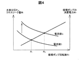
図4は、電流値Iと循環ポンプ64の最適回転数との関係を説明するための図である。図4の横軸は回転数RPを示し、縦軸は水素分圧PH2および消費電力WPを示している。図4には、図2と同様に、電流値IがI1のときの回転数RPと水素分圧PH2との関係、および、電流値IがI2(I1<I2)のときの回転数RPと水素分圧PH2との関係が例示されている。また、図3と同様に、循環ポンプ64の回転数RPと消費電力WPとの関係が示されている。図4には、これらに追加して、電流値IがI1のときに、総合水素損失量MTLが最小となる循環ポンプ64の回転数(最適回転数)R1と、電流値IがI2のときの循環ポンプ64の最適回転数R2(R1<R2)が示されている。燃料電池10は、電流値Iによって最適回転数が異なるため、電流値Iに応じて、総合水素損失量MTLがより小さくなるように回転数RPを変更することによって、発電効率の向上を図ることができる。例えば、電流値IがI1からI2に向かって高くなるとき、回転数RPをR1からR2に向かって高くすることによって、総合水素損失量MTLを抑制することができる。このような制御をおこなえば、例えば、電流値IがI1程度に小さいにもかかわらず、回転数RPをR2以上に高くしてしまい、クロスリーク量の低減量よりも循環ポンプ64の消費電力の増加による水素損失量が大きくなり、結果として発電効率が悪くなることを抑制できる。
FIG. 4 is a diagram for explaining the relationship between the current value I and the optimum rotational speed of the
図5は、制御部20による燃料電池システム100の制御手順の一例を示すフローチャートである。ここでは、制御部20には、図4の電流値I1、I2(I1<I2)および、最適回転数R1、R2(R1<R2)に対応する設定値が記憶されているものとして説明する。電流値I1、I2としては任意の値を設定することができる。また、制御部20は、図2のような回転数RPと水素分圧PH2(ここでは、「目標水素分圧PTH2」に読み替える)との関係を示すマップ(RP−PTH2マップ)を燃料電池10の電流値Iごとに複数記憶しているものとして説明する。
FIG. 5 is a flowchart showing an example of a control procedure of the
制御部20は、燃料電池10の間欠運転時に以下の運転制御を開始する。制御部20は、アノードガス流路の実際の水素分圧PH2が目標水素分圧PTH2となるように水素供給装置55を制御しながら、循環ポンプ64の回転数RPがR1となるように循環ポンプ64を制御する(ステップS110)。このR1は、電流値IがI1のときに総合水素損失量MTLが最小となる回転数として予め特定されている設定値である。アノードガス流路の水素分圧PH2は、例えば、アノードの入口付近の圧力計の圧力に圧損等を考慮して推定されたアノードの出口付近の圧力から特定できる。また、アノードの出口付近に圧力計を設けて、出口付近の圧力計によって計測される燃料電池10の出口近傍のアノード排ガスの圧力から特定してもよい。
The
制御部20は、電流値IがI2より大きくなるまで、循環ポンプ64の回転数RPをR1のままとする(ステップS120)。このI2は上述した設定値であり、循環ポンプ64の回転数RPがR2(R1<R2)のとき総合水素損失量MTLが最小となる電流値である。電流値Iは、燃料電池10を流れる実際の電流値であって、図示しない電流検出部によって検出されたものであってもよいし、外部からの出力要求等に基づいて設定される目標電流値であってもよい。電流値Iは、システム内の各種のセンサ類からの出力信号に基づく計測値から特定されてもよい。また、電流値Iは、例えば、高電位回避のために予め設定されている目標電圧値と、燃料電池10のIV特性から導出されてもよい。燃料電池10のIV特性は、制御部20に予め記憶されていてもよいし、温度を含む燃料電池10の状態から逐次IV特性が設定されてもよい。また、電流値Iが目標電流値の場合、燃料電池システム100の補機類に対して電力を供給するための内的出力要求や、燃料電池車両の運転者などの燃料電池システム100の利用者による外的出力要求に基づいて設定されてもよい。
The
制御部20は、電流値IがI2より大きくなると、循環ポンプ64の回転数RPをR1からR2(R1<R2)に切り換える(ステップS130)。電流値Iの増加と回転数RPの上昇によって目標水素分圧PTH2が変更されるため、制御部20は、水素供給装置55による水素供給量を制御して、水素分圧PH2を新たな目標水素分圧PTH2に近づける。
図6は、電流値Iの増加と回転数RPの上昇によって変更される目標水素分圧PTH2を説明するための図である。ここでは、電流値IがI3からI4(I1<I3<I2<I4)に増加したものとする。図6には、電流値I3および電流値I4における回転数RPと目標水素分圧PTH2との関係がそれぞれ示されている。電流値IがI3からI4に増加したときに循環ポンプ64の回転数RPをR1のままとした場合、目標水素分圧PTH2は、PT1H2からPT2H2に上昇する。一方、電流値IがI3からI4に増加したときに循環ポンプ64の回転数RPをR1からR2に切り換えると、目標水素分圧は、PT2H2よりも低いPT3H2となる。すなわち、電流値Iの増加にともなって循環ポンプ64の回転数RPを上昇させることによって、目標水素分圧PTH2を、回転数RPを上昇させなかった場合における目標水素分圧PTH2よりも低下させることができる。
Figure 6 is a diagram for explaining the target hydrogen partial pressure PT H2 modified by the increase in the rotational speed R P and increase in the current value I. Here, it is assumed that the current value I increases from I 3 to I 4 (I 1 <I 3 <I 2 <I 4 ). Figure 6 shows the relationship between the rotational speed R P and the target hydrogen partial pressure PT H2 at a current value I 3 and the current value I 4 are shown. If the current value I is the rotational speed R P of the circulating
これらにより、循環ポンプ64の回転数RPをR1からR2に切り換えると、回転数RPをR1のままとした場合よりも、総合水素損失量MTLを低減させることができる。すなわち、電流値IがI2より大きい場合、電流値Iに対応する最適回転数はR2よりも大きくなる。例えば、図6では、電流値IがI4(I2<I4)のときの最適回転数はR2よりも大きいR4となる。よって、循環ポンプ64の回転数RPをR1のままとするよりも、R2まで上昇させることにより、回転数RPが電流値Iに対応する最適回転数により近づくため、燃料電池10の発電効率が向上する。
These result, when the rotational speed R P of the circulating
図5に戻り、回転数RPをR2に変更した後、制御部20は、電流値IがI1より小さくなるまで、循環ポンプ64の回転数RPをR2のままとする(ステップS140)。このI1は上述した設定値であり、循環ポンプ64の回転数がR1(R1<R2)とき総合水素損失量MTLが最小となる電流値である。制御部20は、電流値IがI1より小さくなると、循環ポンプ64の回転数RPをR1(R1<R2)に切り換える(ステップS110)。電流値Iの増加と回転数RPの上昇によって目標水素分圧PTH2が変更されるため、制御部20は、水素供給装置55による水素供給量を制御して、水素分圧PH2を新たな目標水素分圧PTH2に近づける。これにより、循環ポンプ64の回転数RPをR2のままとした場合よりも、総合水素損失量MTLを低減させることができる。すなわち、電流値IがI1より小さい場合、電流値Iに対応する最適回転数はR1よりも小さくなる。よって、循環ポンプ64の回転数RPをR2のままとするよりも、R1まで低下させることにより、回転数RPが電流値Iに対応する最適回転数により近づくため、燃料電池10の発電効率が向上する。
Returning to FIG. 5, after the rotational speed R P was changed to R 2, the
制御部20は、燃料電池10の間欠運転状態を解消するまで、上記のステップS110〜S140の処理手順を繰り返す。このように、本実施形態の燃料電池システム100では、燃料電池10の間欠運転時において、循環ポンプ64の回転数RPを、総合水素損失量MTLが最小となる最適回転数に近づくように変更するため、このような変更おこなわない場合よりも、総合水素損失量MTLの低減を図ることができる。
The
図7は、燃料電池10の間欠運転時と通常運転時における回転数RPの制御内容の違いを説明するための図である。図7(a)には、図4と同様に間欠運転時の電流値Iと回転数RPとの関係のほか、通常運転時の一例としての電流値I5と、そのときの回転数RPであるR5が示されている。図7(b)には、間欠運転時と通常運転時における電流値Iと回転数RPとの関係が示されている。図7(b)の横軸は電流値Iを示し、縦軸は回転数RPを示している。 Figure 7 is a diagram for explaining a difference in control contents of the rotation speed R P at the time of a normal operation intermittent operation of the fuel cell 10. FIG. 7A shows the relationship between the current value I during intermittent operation and the rotational speed RP , as well as the current value I 5 as an example during normal operation, and the rotational speed R at that time, as in FIG. R 5 which is P is shown. In FIG. 7 (b), the relationship between the rotational speed R P and the current value I is shown in the normal operation during the intermittent operation. The horizontal axis of FIG. 7 (b) shows the current value I, and the vertical axis represents the rotational speed R P.
制御部20は、燃料電池10の間欠運転時においては、上述のように、総合水素損失量MTLが小さくなるように循環ポンプ64の回転数RPを制御している。すなわち、制御部20は、循環ポンプ64の回転数RPが最適回転数に近づくように循環ポンプ64を制御する。一方、制御部20は、燃料電池10の通常運転時においては、図7(b)に示すように、電流値Iの増加にともなって、循環ポンプ64の回転数RPが増加するように循環ポンプ64を制御する。その結果、燃料電池10の通常運転時においては、循環ポンプ64の回転数RPは最適回転数よりも小さくなる。制御部20は、燃料電池10の通常運転時において、循環ポンプ64の回転数RPを最適回転数に近づくように循環ポンプ64を制御させていない。これは、一般に、アノード排ガスには不純物が含まれているため、アノード排ガスの割合が増えると発電に必要な水素量が得られないおそれがあり、通常運転時には、不純物の少ないインジェクタから供給される水素の割合を多くする必要があるためである。また、通常運転時には、アノードに供給される水素は発電によってすぐに消費されるため、クロスリークが問題となりにくいためである。
以上説明した、本実施形態の燃料電池システム100によれば、制御部20は、循環ポンプ64の回転数RPが最適回転数に近づくように循環ポンプ64を制御するため、クロスリーク量MLを低減させつつ、クロスリーク量MLの低減のための循環ポンプ64の駆動に要する消費電力WPに相当する水素の損失量を抑制できる。すなわち、循環ポンプ64の回転数を上昇させ、アノード排ガスの循環量を増やすことによって、目標の電流値を発生させるために必要な水素ストイキ比Cを確保しつつ、燃料電池10のアノードガス流路の水素分圧PH2を下げてクロスリーク量MLを低減させる。一方で、循環ポンプ64の回転数RPを上昇させすぎないことによって、クロスリーク量MLの低減のための循環ポンプの駆動に要する消費電力WPに相当する水素の損失量を抑制できる。これにより、燃料電池の発電効率の向上を図ることができる。
Described above, according to the
・変形例:
なお、この発明は上記の実施形態や実施形態に限られるものではなく、その要旨を逸脱しない範囲において種々の態様において実施することが可能であり、例えば次のような変形も可能である。
・ Modification:
The present invention is not limited to the above-described embodiments and embodiments, and can be implemented in various modes without departing from the gist thereof. For example, the following modifications are possible.
・変形例1:
第1実施形態では、制御部20は、循環ポンプ64の回転数RPをR1とR2のいずれかに切り換えるものとして構成として説明した。しかし、制御部20は、電流値Iに応じて、最適回転数を特定し、循環ポンプ64を制御して、その回転数RPを、特定した最適回転数に変更する構成であってもよい。例えば、制御部20には、燃料電池10の電流値Iごとの最適回転数および目標水素分圧PTH2が予め記憶されているものとする。この場合、制御部20は、電流値Iから最適回転数と目標水素分圧PTH2を特定することができる。また、例えば、制御部20には、燃料電池10の電流値IごとのRP−PTH2マップと、図3に示す、回転数RPと消費電力WPとの関係を示したマップ(RP−WPマップ)とが記憶されているものとする。この場合、制御部20は、RP−PTH2マップから各回転数RPにおけるクロスリーク量MLを特定し、RP−WPマップから各回転数RPにおける消費電力WPを特定することができる。特定した各回転数RPにおけるクロスリーク量と消費電力WPとの組合せを上述した式(3)にあてはめることによって、総合水素損失量MTLが最小となる最適回転数を特定することができる。この構成であっても、水素の損失を低減させて発電効率の向上を図ることができる。
・ Modification 1:
In the first embodiment, the
・変形例2:
本実施形態では、図5の運転制御は燃料電池10の間欠運転時に実行されるものとして説明した。しかし、図5の運転制御は、燃料電池10の間欠運転時以外の状態においても実行されてもよい。この場合であっても、水素の損失を低減させて発電効率の向上を図ることができる。
In the present embodiment, the operation control of FIG. 5 has been described as being executed during intermittent operation of the fuel cell 10. However, the operation control of FIG. 5 may be executed even in a state other than the intermittent operation of the fuel cell 10. Even in this case, it is possible to improve power generation efficiency by reducing hydrogen loss.
1…電解質膜
2…カソード
3…アノード
10…燃料電池
20…制御部
30…カソードガス供給部
31…カソードガス配管
32…エアコンプレッサ
33…エアフロメータ
34…供給バルブ
35…圧力計測部
40…カソード排ガス排出部
41…カソード排ガス配管
43…排出バルブ
50…アノードガス供給部
51…アノードガス配管
52…水素タンク
53…開閉弁
54…レギュレータ
55…水素供給装置
56…圧力計測部
60…アノードガス循環部
61…アノード排ガス配管
62…気液分離部
63…アノードガス循環配管
64…循環ポンプ
65…アノード排水配管
66…排水弁
100…燃料電池システム
DESCRIPTION OF
Claims (3)
アノードとカソードとを備える単セルを含む燃料電池と、
前記アノードに水素ガスを供給する水素供給装置と、
前記燃料電池の発電に使用されずに前記アノードから排出される水素を含むアノード排ガスを再び前記アノードに供給して前記アノード排ガスを循環させる循環ポンプと、
前記水素供給装置による水素ガスの供給量、および、前記循環ポンプの回転数を制御する制御部と、を備え、
前記制御部は、前記燃料電池の間欠運転において、所定の電流値において、前記循環ポンプを駆動させるために必要な電力に相当する水素量と、前記燃料電池のアノード側からカソード側へ通過する水素量との合計である総合水素損失量が最小となる前記循環ポンプの最適回転数に回転数が近づくように前記循環ポンプを駆動させ、
前記制御部は、
二つの目標電流値に対応する前記循環ポンプの最適回転数をそれぞれ実現する設定を記憶しており、
前記間欠運転において、
電流値が増加し、前記二つの目標電流値のうち大きい方の目標電流値を上回った場合に、前記大きい方の目標電流値に対応する最適回転数を実現する設定で、前記循環ポンプの運転を行い、
電流値が減少し、前記二つの目標電流値のうち小さい方の目標電流値を下回った場合に、前記小さい方の目標電流値に対応する最適回転数を実現する設定で、前記循環ポンプの運転を行い、
電流値が変化し、前記大きい方の目標電流値を下回った場合、および前記小さい方の目標電流値を上回った場合は、それまでになされた設定を維持して前記循環ポンプの運転を行う、燃料電池システム。 A fuel cell system,
A fuel cell comprising a single cell comprising an anode and a cathode;
A hydrogen supply device for supplying hydrogen gas to the anode;
A circulation pump for supplying anode exhaust gas containing hydrogen discharged from the anode without being used for power generation of the fuel cell to the anode and circulating the anode exhaust gas;
A control unit for controlling the amount of hydrogen gas supplied by the hydrogen supply device and the number of revolutions of the circulation pump;
In the intermittent operation of the fuel cell , the control unit has an amount of hydrogen corresponding to electric power required to drive the circulation pump at a predetermined current value, and hydrogen passing from the anode side to the cathode side of the fuel cell. the circulation pump is driven so that overall the hydrogen loss is the sum of the amount of rotation speed approaches the optimum rotational speed of the circulating pump with the minimum,
The controller is
Stores settings for realizing the optimum rotational speed of the circulating pump corresponding to two target current values, respectively.
In the intermittent operation,
When the current value increases and exceeds the larger target current value of the two target current values, the circulating pump is operated with a setting that realizes the optimum rotational speed corresponding to the larger target current value. And
When the current value decreases and falls below the smaller target current value of the two target current values, the circulating pump is operated with a setting that realizes the optimum rotational speed corresponding to the smaller target current value. And
If the current value changes and falls below the larger target current value, and exceeds the smaller target current value, the circulating pump is operated while maintaining the settings made so far . Fuel cell system.
前記制御部は、前記燃料電池の通常運転と前記間欠運転とを切り替え、
前記燃料電池の通常運転時において、前記総合水素損失量が最小となる最適回転数よりも小さい回転数で前記循環ポンプを駆動させ、
前記燃料電池の間欠運転時に所定の電流値において、前記総合水素損失量が最小となる前記最適回転数に回転数が近づくように前記循環ポンプを駆動させる、燃料電池システム。 The fuel cell system according to claim 1,
The control unit may switch between normal said the operation intermittent operation of the fuel cell,
During the normal operation of the fuel cell, the circulating pump is driven at a rotational speed smaller than the optimal rotational speed at which the total hydrogen loss is minimized,
A fuel cell system that drives the circulation pump so that the rotational speed approaches the optimum rotational speed at which the total hydrogen loss amount is minimized at a predetermined current value during intermittent operation of the fuel cell.
燃料電池の通常運転時において、前記燃料電池から得られる電流の増加にともなって、水素ガスの供給量を増加させ、
前記燃料電池の間欠運転時において、
前記燃料電池から得られる電流の増加にともなって、前記燃料電池のアノードから排出されて再び前記アノードに供給されるアノード排ガスの流量を増加させ、前記アノードの水素分圧を、前記燃料電池の通常運転時において前記電流を発生させるために必要となる水素分圧よりも低下させ、
あらかじめ記憶されている設定であって、二つの目標電流値に対応する循環ポンプの最適回転数をそれぞれ実現する設定に基づいて、
電流値が増加し、前記二つの目標電流値のうち大きい方の目標電流値を上回った場合に、前記大きい方の目標電流値に対応する最適回転数を実現する設定で、前記循環ポンプの運転を行い、
電流値が減少し、前記二つの目標電流値のうち小さい方の目標電流値を下回った場合に、前記小さい方の目標電流値に対応する最適回転数を実現する設定で、前記循環ポンプの運転を行い、
電流値が変化し、前記大きい方の目標電流値を下回った場合、および前記小さい方の目標電流値を上回った場合は、それまでになされた設定を維持して前記循環ポンプの運転を行う、制御方法。 A control method for a fuel cell system, comprising:
During normal operation of the fuel cell, with an increase in current obtained from the fuel cell, the supply amount of hydrogen gas is increased,
During intermittent operation of the fuel cell,
As the current obtained from the fuel cell increases, the flow rate of the anode exhaust gas discharged from the anode of the fuel cell and supplied to the anode again is increased, and the hydrogen partial pressure of the anode is adjusted to the normal value of the fuel cell. Lower than the hydrogen partial pressure required to generate the current during operation ,
Based on the settings stored in advance and realizing the optimum rotational speed of the circulation pump corresponding to the two target current values,
When the current value increases and exceeds the larger target current value of the two target current values, the circulating pump is operated with a setting that realizes the optimum rotational speed corresponding to the larger target current value. And
When the current value decreases and falls below the smaller target current value of the two target current values, the circulating pump is operated with a setting that realizes the optimum rotational speed corresponding to the smaller target current value. And
If the current value changes and falls below the larger target current value, and exceeds the smaller target current value, the circulating pump is operated while maintaining the settings made so far . Control method.
Priority Applications (6)
| Application Number | Priority Date | Filing Date | Title |
|---|---|---|---|
| JP2014232249A JP6222050B2 (en) | 2014-11-15 | 2014-11-15 | Fuel cell system and control method of fuel cell system |
| KR1020150153776A KR101809796B1 (en) | 2014-11-15 | 2015-11-03 | Fuel cell system and fuel cell system control method |
| CA2911565A CA2911565C (en) | 2014-11-15 | 2015-11-06 | Fuel cell system and fuel cell system control method |
| US14/938,377 US9905866B2 (en) | 2014-11-15 | 2015-11-11 | Fuel cell system and fuel cell system control method |
| DE102015119429.5A DE102015119429B4 (en) | 2014-11-15 | 2015-11-11 | Fuel cell system and control method for a fuel cell system |
| CN201510781764.3A CN105609824B (en) | 2014-11-15 | 2015-11-13 | The control method of fuel cell system and fuel cell system |
Applications Claiming Priority (1)
| Application Number | Priority Date | Filing Date | Title |
|---|---|---|---|
| JP2014232249A JP6222050B2 (en) | 2014-11-15 | 2014-11-15 | Fuel cell system and control method of fuel cell system |
Publications (3)
| Publication Number | Publication Date |
|---|---|
| JP2016096085A JP2016096085A (en) | 2016-05-26 |
| JP2016096085A5 JP2016096085A5 (en) | 2016-08-04 |
| JP6222050B2 true JP6222050B2 (en) | 2017-11-01 |
Family
ID=55855133
Family Applications (1)
| Application Number | Title | Priority Date | Filing Date |
|---|---|---|---|
| JP2014232249A Active JP6222050B2 (en) | 2014-11-15 | 2014-11-15 | Fuel cell system and control method of fuel cell system |
Country Status (6)
| Country | Link |
|---|---|
| US (1) | US9905866B2 (en) |
| JP (1) | JP6222050B2 (en) |
| KR (1) | KR101809796B1 (en) |
| CN (1) | CN105609824B (en) |
| CA (1) | CA2911565C (en) |
| DE (1) | DE102015119429B4 (en) |
Families Citing this family (8)
| Publication number | Priority date | Publication date | Assignee | Title |
|---|---|---|---|---|
| CN107230794A (en) * | 2017-06-02 | 2017-10-03 | 中国东方电气集团有限公司 | The dynamical system and the vehicles of fuel cell |
| CN108400359A (en) * | 2018-05-09 | 2018-08-14 | 湖南优加特装智能科技有限公司 | Device for recovering tail gas and hydrogen fuel cell with it |
| CN109830709B (en) * | 2019-02-01 | 2020-01-14 | 清华大学 | Fuel cell hydrogen supply control method, computer device, and storage medium |
| CN114583220B (en) * | 2020-11-30 | 2023-07-21 | 宇通客车股份有限公司 | Fuel cell water content control method, fuel cell system and fuel cell vehicle |
| CN112659928B (en) * | 2020-12-25 | 2022-05-13 | 中通客车股份有限公司 | Vehicle-mounted proton exchange membrane fuel cell dynamic loading and unloading control method and system |
| CN113669155B (en) * | 2021-08-25 | 2022-11-15 | 一汽解放汽车有限公司 | Combined power system and commercial vehicle |
| CN115020760B (en) * | 2022-08-09 | 2022-11-08 | 佛山市清极能源科技有限公司 | Idling control method of fuel cell system |
| CN115425262A (en) * | 2022-11-04 | 2022-12-02 | 北京亿华通科技股份有限公司 | Liquid hydrogen system fuel cell control method and device, fuel cell and vehicle |
Family Cites Families (16)
| Publication number | Priority date | Publication date | Assignee | Title |
|---|---|---|---|---|
| AU2003286063A1 (en) * | 2002-11-27 | 2004-06-18 | Hydrogenics Corporation | Method of operating a fuel cell power system to deliver constant power |
| US7670700B2 (en) | 2003-09-05 | 2010-03-02 | Denso Corporation | Fuel cell system, related method and current measuring device for fuel cell system |
| JP4656599B2 (en) * | 2004-01-22 | 2011-03-23 | トヨタ自動車株式会社 | Fuel cell system and driving method of fuel cell system |
| JP4867199B2 (en) | 2005-05-25 | 2012-02-01 | トヨタ自動車株式会社 | Fuel cell system |
| JP4984322B2 (en) | 2007-03-20 | 2012-07-25 | トヨタ自動車株式会社 | Fuel cell system |
| JP4936126B2 (en) * | 2007-04-16 | 2012-05-23 | トヨタ自動車株式会社 | Fuel cell system |
| JP5057284B2 (en) | 2007-07-27 | 2012-10-24 | トヨタ自動車株式会社 | Fuel cell system and control method thereof |
| JP4735642B2 (en) | 2007-12-27 | 2011-07-27 | 日産自動車株式会社 | FUEL CELL SYSTEM AND CONTROL METHOD FOR FUEL CELL SYSTEM |
| JP4605263B2 (en) | 2008-07-11 | 2011-01-05 | トヨタ自動車株式会社 | Fuel cell system |
| JP4743455B2 (en) * | 2009-05-26 | 2011-08-10 | トヨタ自動車株式会社 | Fuel cell system |
| JP4797092B2 (en) * | 2009-07-02 | 2011-10-19 | 本田技研工業株式会社 | Fuel cell vehicle and control method of fuel cell system |
| JP5409705B2 (en) | 2011-05-25 | 2014-02-05 | 本田技研工業株式会社 | Fuel cell system and control method thereof |
| JP5757227B2 (en) | 2011-12-13 | 2015-07-29 | トヨタ自動車株式会社 | Fuel cell system and control method thereof |
| JP5497812B2 (en) * | 2012-02-13 | 2014-05-21 | 株式会社大都技研 | Amusement stand |
| JP6121229B2 (en) * | 2013-04-26 | 2017-04-26 | 本田技研工業株式会社 | Fuel cell system and control method of fuel cell system |
| JP2014232249A (en) | 2013-05-30 | 2014-12-11 | 株式会社Adeka | Photosensitive composition |
-
2014
- 2014-11-15 JP JP2014232249A patent/JP6222050B2/en active Active
-
2015
- 2015-11-03 KR KR1020150153776A patent/KR101809796B1/en active IP Right Grant
- 2015-11-06 CA CA2911565A patent/CA2911565C/en active Active
- 2015-11-11 DE DE102015119429.5A patent/DE102015119429B4/en active Active
- 2015-11-11 US US14/938,377 patent/US9905866B2/en active Active
- 2015-11-13 CN CN201510781764.3A patent/CN105609824B/en active Active
Also Published As
| Publication number | Publication date |
|---|---|
| CN105609824A (en) | 2016-05-25 |
| CA2911565A1 (en) | 2016-05-15 |
| JP2016096085A (en) | 2016-05-26 |
| DE102015119429A1 (en) | 2016-05-19 |
| DE102015119429B4 (en) | 2018-09-06 |
| KR20160058683A (en) | 2016-05-25 |
| DE102015119429A8 (en) | 2016-07-14 |
| US20160141651A1 (en) | 2016-05-19 |
| CA2911565C (en) | 2017-10-10 |
| CN105609824B (en) | 2018-01-23 |
| KR101809796B1 (en) | 2017-12-15 |
| US9905866B2 (en) | 2018-02-27 |
Similar Documents
| Publication | Publication Date | Title |
|---|---|---|
| JP6222050B2 (en) | Fuel cell system and control method of fuel cell system | |
| US10122030B2 (en) | Fuel cell system and method of controlling operation of fuel cell | |
| JP5120594B2 (en) | Fuel cell system and operation method thereof | |
| JP4993293B2 (en) | Fuel cell system and moving body | |
| KR101272511B1 (en) | Method for controlling air feed rate to improve the performance of fuel cell | |
| JP2009016170A (en) | Fuel cell system and control device of fuel cell system | |
| US8080342B2 (en) | Fuel cell system | |
| JP2007220538A (en) | Fuel cell system | |
| WO2013105590A1 (en) | Fuel cell system | |
| JP5812423B2 (en) | Fuel cell system | |
| JP5136415B2 (en) | Fuel cell system | |
| JP2019129089A (en) | Fuel cell system | |
| JP2011150794A (en) | Fuel cell system, and control method therefor | |
| JP5880618B2 (en) | Fuel cell system and control method thereof | |
| CN107452974B (en) | Hydrogen deficiency judgment method and hydrogen deficiency judgment device | |
| JP6335947B2 (en) | Stop control method for fuel cell system | |
| JP6304366B2 (en) | Fuel cell system | |
| JP2013182690A (en) | Fuel cell system | |
| JP6200009B2 (en) | Operation method of fuel cell system | |
| JP6389835B2 (en) | Pressure control method during output acceleration of fuel cell system | |
| JP5057086B2 (en) | Pump drive control device | |
| JP2013182688A (en) | Fuel cell system | |
| JP2013134866A (en) | Fuel cell system and fuel cell system control method | |
| JP2015201408A (en) | fuel cell system | |
| JP2013251092A (en) | Fuel cell system for vehicle |
Legal Events
| Date | Code | Title | Description |
|---|---|---|---|
| A621 | Written request for application examination |
Free format text: JAPANESE INTERMEDIATE CODE: A621 Effective date: 20160309 |
|
| A521 | Written amendment |
Free format text: JAPANESE INTERMEDIATE CODE: A523 Effective date: 20160615 |
|
| A977 | Report on retrieval |
Free format text: JAPANESE INTERMEDIATE CODE: A971007 Effective date: 20170216 |
|
| A131 | Notification of reasons for refusal |
Free format text: JAPANESE INTERMEDIATE CODE: A131 Effective date: 20170221 |
|
| A521 | Written amendment |
Free format text: JAPANESE INTERMEDIATE CODE: A523 Effective date: 20170421 |
|
| TRDD | Decision of grant or rejection written | ||
| A01 | Written decision to grant a patent or to grant a registration (utility model) |
Free format text: JAPANESE INTERMEDIATE CODE: A01 Effective date: 20170905 |
|
| A61 | First payment of annual fees (during grant procedure) |
Free format text: JAPANESE INTERMEDIATE CODE: A61 Effective date: 20170918 |
|
| R151 | Written notification of patent or utility model registration |
Ref document number: 6222050 Country of ref document: JP Free format text: JAPANESE INTERMEDIATE CODE: R151 |