JP6304366B2 - Fuel cell system - Google Patents
Fuel cell system Download PDFInfo
- Publication number
- JP6304366B2 JP6304366B2 JP2016507213A JP2016507213A JP6304366B2 JP 6304366 B2 JP6304366 B2 JP 6304366B2 JP 2016507213 A JP2016507213 A JP 2016507213A JP 2016507213 A JP2016507213 A JP 2016507213A JP 6304366 B2 JP6304366 B2 JP 6304366B2
- Authority
- JP
- Japan
- Prior art keywords
- flow rate
- control
- wet
- fuel cell
- cathode gas
- Prior art date
- Legal status (The legal status is an assumption and is not a legal conclusion. Google has not performed a legal analysis and makes no representation as to the accuracy of the status listed.)
- Expired - Fee Related
Links
- 239000000446 fuel Substances 0.000 title claims description 237
- 238000004364 calculation method Methods 0.000 claims description 127
- 238000010248 power generation Methods 0.000 claims description 27
- 230000007423 decrease Effects 0.000 claims description 14
- 238000009736 wetting Methods 0.000 claims description 11
- 230000007246 mechanism Effects 0.000 claims description 3
- 230000005611 electricity Effects 0.000 claims 1
- 239000007789 gas Substances 0.000 description 625
- 239000000498 cooling water Substances 0.000 description 37
- 238000010586 diagram Methods 0.000 description 26
- 239000012528 membrane Substances 0.000 description 23
- 239000003792 electrolyte Substances 0.000 description 22
- 238000010992 reflux Methods 0.000 description 20
- 238000000034 method Methods 0.000 description 18
- XLYOFNOQVPJJNP-UHFFFAOYSA-N water Chemical compound O XLYOFNOQVPJJNP-UHFFFAOYSA-N 0.000 description 18
- 230000008569 process Effects 0.000 description 17
- 230000001276 controlling effect Effects 0.000 description 13
- 238000005259 measurement Methods 0.000 description 11
- 238000009792 diffusion process Methods 0.000 description 8
- 230000001105 regulatory effect Effects 0.000 description 8
- 239000003054 catalyst Substances 0.000 description 7
- 238000012545 processing Methods 0.000 description 7
- 238000010926 purge Methods 0.000 description 7
- 230000006870 function Effects 0.000 description 6
- 230000003247 decreasing effect Effects 0.000 description 5
- 230000008859 change Effects 0.000 description 4
- BASFCYQUMIYNBI-UHFFFAOYSA-N platinum Chemical compound [Pt] BASFCYQUMIYNBI-UHFFFAOYSA-N 0.000 description 4
- UFHFLCQGNIYNRP-UHFFFAOYSA-N Hydrogen Chemical compound [H][H] UFHFLCQGNIYNRP-UHFFFAOYSA-N 0.000 description 3
- 238000001816 cooling Methods 0.000 description 3
- 238000003411 electrode reaction Methods 0.000 description 3
- 230000002159 abnormal effect Effects 0.000 description 2
- 230000005856 abnormality Effects 0.000 description 2
- 238000012937 correction Methods 0.000 description 2
- 239000001257 hydrogen Substances 0.000 description 2
- 229910052739 hydrogen Inorganic materials 0.000 description 2
- 229910052697 platinum Inorganic materials 0.000 description 2
- 230000001172 regenerating effect Effects 0.000 description 2
- 230000004044 response Effects 0.000 description 2
- 239000004065 semiconductor Substances 0.000 description 2
- 238000011144 upstream manufacturing Methods 0.000 description 2
- OKTJSMMVPCPJKN-UHFFFAOYSA-N Carbon Chemical compound [C] OKTJSMMVPCPJKN-UHFFFAOYSA-N 0.000 description 1
- YCKRFDGAMUMZLT-UHFFFAOYSA-N Fluorine atom Chemical compound [F] YCKRFDGAMUMZLT-UHFFFAOYSA-N 0.000 description 1
- 230000002528 anti-freeze Effects 0.000 description 1
- QVGXLLKOCUKJST-UHFFFAOYSA-N atomic oxygen Chemical compound [O] QVGXLLKOCUKJST-UHFFFAOYSA-N 0.000 description 1
- 230000008901 benefit Effects 0.000 description 1
- 230000002457 bidirectional effect Effects 0.000 description 1
- 238000009529 body temperature measurement Methods 0.000 description 1
- 229910052799 carbon Inorganic materials 0.000 description 1
- 239000006229 carbon black Substances 0.000 description 1
- 239000002826 coolant Substances 0.000 description 1
- 238000001514 detection method Methods 0.000 description 1
- 230000000694 effects Effects 0.000 description 1
- 239000004744 fabric Substances 0.000 description 1
- 229910052731 fluorine Inorganic materials 0.000 description 1
- 239000011737 fluorine Substances 0.000 description 1
- 239000003014 ion exchange membrane Substances 0.000 description 1
- 230000004048 modification Effects 0.000 description 1
- 238000012986 modification Methods 0.000 description 1
- 239000007800 oxidant agent Substances 0.000 description 1
- 230000001590 oxidative effect Effects 0.000 description 1
- 239000001301 oxygen Substances 0.000 description 1
- 229910052760 oxygen Inorganic materials 0.000 description 1
- 239000002245 particle Substances 0.000 description 1
- 239000011347 resin Substances 0.000 description 1
- 229920005989 resin Polymers 0.000 description 1
- 230000001360 synchronised effect Effects 0.000 description 1
Images


Classifications
-
- H—ELECTRICITY
- H01—ELECTRIC ELEMENTS
- H01M—PROCESSES OR MEANS, e.g. BATTERIES, FOR THE DIRECT CONVERSION OF CHEMICAL ENERGY INTO ELECTRICAL ENERGY
- H01M8/00—Fuel cells; Manufacture thereof
- H01M8/04—Auxiliary arrangements, e.g. for control of pressure or for circulation of fluids
- H01M8/04298—Processes for controlling fuel cells or fuel cell systems
- H01M8/04694—Processes for controlling fuel cells or fuel cell systems characterised by variables to be controlled
- H01M8/04746—Pressure; Flow
- H01M8/04753—Pressure; Flow of fuel cell reactants
-
- H—ELECTRICITY
- H01—ELECTRIC ELEMENTS
- H01M—PROCESSES OR MEANS, e.g. BATTERIES, FOR THE DIRECT CONVERSION OF CHEMICAL ENERGY INTO ELECTRICAL ENERGY
- H01M8/00—Fuel cells; Manufacture thereof
- H01M8/04—Auxiliary arrangements, e.g. for control of pressure or for circulation of fluids
- H01M8/04082—Arrangements for control of reactant parameters, e.g. pressure or concentration
- H01M8/04089—Arrangements for control of reactant parameters, e.g. pressure or concentration of gaseous reactants
- H01M8/04097—Arrangements for control of reactant parameters, e.g. pressure or concentration of gaseous reactants with recycling of the reactants
-
- H—ELECTRICITY
- H01—ELECTRIC ELEMENTS
- H01M—PROCESSES OR MEANS, e.g. BATTERIES, FOR THE DIRECT CONVERSION OF CHEMICAL ENERGY INTO ELECTRICAL ENERGY
- H01M8/00—Fuel cells; Manufacture thereof
- H01M8/04—Auxiliary arrangements, e.g. for control of pressure or for circulation of fluids
- H01M8/04223—Auxiliary arrangements, e.g. for control of pressure or for circulation of fluids during start-up or shut-down; Depolarisation or activation, e.g. purging; Means for short-circuiting defective fuel cells
- H01M8/04231—Purging of the reactants
-
- H—ELECTRICITY
- H01—ELECTRIC ELEMENTS
- H01M—PROCESSES OR MEANS, e.g. BATTERIES, FOR THE DIRECT CONVERSION OF CHEMICAL ENERGY INTO ELECTRICAL ENERGY
- H01M8/00—Fuel cells; Manufacture thereof
- H01M8/04—Auxiliary arrangements, e.g. for control of pressure or for circulation of fluids
- H01M8/04298—Processes for controlling fuel cells or fuel cell systems
- H01M8/04313—Processes for controlling fuel cells or fuel cell systems characterised by the detection or assessment of variables; characterised by the detection or assessment of failure or abnormal function
- H01M8/0438—Pressure; Ambient pressure; Flow
- H01M8/04388—Pressure; Ambient pressure; Flow of anode reactants at the inlet or inside the fuel cell
-
- H—ELECTRICITY
- H01—ELECTRIC ELEMENTS
- H01M—PROCESSES OR MEANS, e.g. BATTERIES, FOR THE DIRECT CONVERSION OF CHEMICAL ENERGY INTO ELECTRICAL ENERGY
- H01M8/00—Fuel cells; Manufacture thereof
- H01M8/04—Auxiliary arrangements, e.g. for control of pressure or for circulation of fluids
- H01M8/04298—Processes for controlling fuel cells or fuel cell systems
- H01M8/04313—Processes for controlling fuel cells or fuel cell systems characterised by the detection or assessment of variables; characterised by the detection or assessment of failure or abnormal function
- H01M8/0438—Pressure; Ambient pressure; Flow
- H01M8/04395—Pressure; Ambient pressure; Flow of cathode reactants at the inlet or inside the fuel cell
-
- H—ELECTRICITY
- H01—ELECTRIC ELEMENTS
- H01M—PROCESSES OR MEANS, e.g. BATTERIES, FOR THE DIRECT CONVERSION OF CHEMICAL ENERGY INTO ELECTRICAL ENERGY
- H01M8/00—Fuel cells; Manufacture thereof
- H01M8/04—Auxiliary arrangements, e.g. for control of pressure or for circulation of fluids
- H01M8/04298—Processes for controlling fuel cells or fuel cell systems
- H01M8/04313—Processes for controlling fuel cells or fuel cell systems characterised by the detection or assessment of variables; characterised by the detection or assessment of failure or abnormal function
- H01M8/04492—Humidity; Ambient humidity; Water content
- H01M8/04529—Humidity; Ambient humidity; Water content of the electrolyte
-
- H—ELECTRICITY
- H01—ELECTRIC ELEMENTS
- H01M—PROCESSES OR MEANS, e.g. BATTERIES, FOR THE DIRECT CONVERSION OF CHEMICAL ENERGY INTO ELECTRICAL ENERGY
- H01M8/00—Fuel cells; Manufacture thereof
- H01M8/04—Auxiliary arrangements, e.g. for control of pressure or for circulation of fluids
- H01M8/04298—Processes for controlling fuel cells or fuel cell systems
- H01M8/04313—Processes for controlling fuel cells or fuel cell systems characterised by the detection or assessment of variables; characterised by the detection or assessment of failure or abnormal function
- H01M8/04537—Electric variables
- H01M8/04604—Power, energy, capacity or load
- H01M8/04619—Power, energy, capacity or load of fuel cell stacks
-
- H—ELECTRICITY
- H01—ELECTRIC ELEMENTS
- H01M—PROCESSES OR MEANS, e.g. BATTERIES, FOR THE DIRECT CONVERSION OF CHEMICAL ENERGY INTO ELECTRICAL ENERGY
- H01M8/00—Fuel cells; Manufacture thereof
- H01M8/04—Auxiliary arrangements, e.g. for control of pressure or for circulation of fluids
- H01M8/04298—Processes for controlling fuel cells or fuel cell systems
- H01M8/04694—Processes for controlling fuel cells or fuel cell systems characterised by variables to be controlled
- H01M8/04828—Humidity; Water content
- H01M8/0485—Humidity; Water content of the electrolyte
-
- H—ELECTRICITY
- H01—ELECTRIC ELEMENTS
- H01M—PROCESSES OR MEANS, e.g. BATTERIES, FOR THE DIRECT CONVERSION OF CHEMICAL ENERGY INTO ELECTRICAL ENERGY
- H01M8/00—Fuel cells; Manufacture thereof
- H01M8/10—Fuel cells with solid electrolytes
- H01M2008/1095—Fuel cells with polymeric electrolytes
-
- H—ELECTRICITY
- H01—ELECTRIC ELEMENTS
- H01M—PROCESSES OR MEANS, e.g. BATTERIES, FOR THE DIRECT CONVERSION OF CHEMICAL ENERGY INTO ELECTRICAL ENERGY
- H01M2250/00—Fuel cells for particular applications; Specific features of fuel cell system
- H01M2250/20—Fuel cells in motive systems, e.g. vehicle, ship, plane
-
- Y—GENERAL TAGGING OF NEW TECHNOLOGICAL DEVELOPMENTS; GENERAL TAGGING OF CROSS-SECTIONAL TECHNOLOGIES SPANNING OVER SEVERAL SECTIONS OF THE IPC; TECHNICAL SUBJECTS COVERED BY FORMER USPC CROSS-REFERENCE ART COLLECTIONS [XRACs] AND DIGESTS
- Y02—TECHNOLOGIES OR APPLICATIONS FOR MITIGATION OR ADAPTATION AGAINST CLIMATE CHANGE
- Y02E—REDUCTION OF GREENHOUSE GAS [GHG] EMISSIONS, RELATED TO ENERGY GENERATION, TRANSMISSION OR DISTRIBUTION
- Y02E60/00—Enabling technologies; Technologies with a potential or indirect contribution to GHG emissions mitigation
- Y02E60/30—Hydrogen technology
- Y02E60/50—Fuel cells
-
- Y—GENERAL TAGGING OF NEW TECHNOLOGICAL DEVELOPMENTS; GENERAL TAGGING OF CROSS-SECTIONAL TECHNOLOGIES SPANNING OVER SEVERAL SECTIONS OF THE IPC; TECHNICAL SUBJECTS COVERED BY FORMER USPC CROSS-REFERENCE ART COLLECTIONS [XRACs] AND DIGESTS
- Y02—TECHNOLOGIES OR APPLICATIONS FOR MITIGATION OR ADAPTATION AGAINST CLIMATE CHANGE
- Y02T—CLIMATE CHANGE MITIGATION TECHNOLOGIES RELATED TO TRANSPORTATION
- Y02T90/00—Enabling technologies or technologies with a potential or indirect contribution to GHG emissions mitigation
- Y02T90/40—Application of hydrogen technology to transportation, e.g. using fuel cells
Description
本発明は、アノードガス及びカソードガスの供給を受けて発電する燃料電池を備える燃料電池システムに関する。 The present invention relates to a fuel cell system including a fuel cell that generates power by receiving supply of anode gas and cathode gas.
燃料電池では、電解質膜の湿潤度が高くなり過ぎたり低くなり過ぎたりすると、発電性能が低下する。燃料電池を効率的に発電させるためには、燃料電池の電解質膜を適度な湿潤度に維持することが重要である。 In the fuel cell, when the wetness of the electrolyte membrane becomes too high or too low, the power generation performance is degraded. In order to efficiently generate power in the fuel cell, it is important to maintain the electrolyte membrane of the fuel cell at an appropriate wetness.
特表2010−538415号公報には、アノードガス流量及びカソードガス流量の少なくとも一方を制御することで、燃料電池の湿潤度を調整する燃料電池システムが開示されている。 Japanese Patent Application Publication No. 2010-538415 discloses a fuel cell system that adjusts the wetness of a fuel cell by controlling at least one of an anode gas flow rate and a cathode gas flow rate.
上記公報には、アノードガス流量制御やカソードガス流量制御によって燃料電池の湿潤度が調整可能であることが開示されているにすぎず、アノードガス流量制御及びカソードガス流量制御に基づいて湿潤度を適切に調整することは開示されていない。 The above publication only discloses that the wetness of the fuel cell can be adjusted by controlling the anode gas flow rate or the cathode gas flow rate, and the wetness is adjusted based on the anode gas flow rate control and the cathode gas flow rate control. Proper adjustment is not disclosed.
一方、本願発明者らは、燃料電池の湿潤制御に関し、カソードガス流量が多い場合にアノードガス流量を変更しても、アノードガス流量制御によって燃料電池の湿潤度をほとんど調整することができないことを見出した。つまり、アノードガス流量を制御して燃料電池の湿潤度を調整する場合には、カソードガス流量をできる限り少なくしておくことが必要である。そのため、この点について考慮していない従来の燃料電池システムでは、湿潤制御の際に、コンプレッサ又はポンプ等によって構成されるカソードガス流量制御部やアノードガス流量制御部を必要以上に動作させてしまうおそれがある。 On the other hand, the inventors of the present application have found that the wetness of the fuel cell can hardly be adjusted by the anode gas flow rate control even if the anode gas flow rate is changed when the cathode gas flow rate is high. I found it. That is, when adjusting the wetness of the fuel cell by controlling the anode gas flow rate, it is necessary to reduce the cathode gas flow rate as much as possible. Therefore, in the conventional fuel cell system in which this point is not taken into account, the cathode gas flow rate control unit and the anode gas flow rate control unit configured by a compressor or a pump may be operated more than necessary during the wet control. There is.
本発明の目的は、カソードガス流量制御部やアノードガス流量制御部を適切に制御し、燃料電池の湿潤度を調整可能な燃料電池システムを提供することである。 An object of the present invention is to provide a fuel cell system capable of appropriately controlling the cathode gas flow rate control unit and the anode gas flow rate control unit and adjusting the wetness of the fuel cell.
本発明のある態様によれば、アノードガス及びカソードガスの供給を受けて発電する燃料電池と、前記燃料電池から排出されたアノードオフガスを当該燃料電池に供給するように構成された循環機構と、を備える燃料電池システムが提供される。燃料電池システムは、前記燃料電池の湿潤状態の目標値である湿潤目標値を算出する湿潤目標値算出部と、前記燃料電池に対する発電要求に基づいてカソードガス要求流量を算出するガス要求流量算出部と、ドライ制御時に少なくとも前記湿潤目標値と前記カソードガス要求流量とに基づいて湿潤制御用アノードガス循環流量を算出する湿潤制御用アノードガス流量算出部と、前記湿潤制御用アノードガス循環流量に基づいてアノードガス循環流量を制御するアノードガス流量制御部と、を備える。また、燃料電池システムは、ドライ制御時に少なくとも前記湿潤目標値と前記アノードガス流量制御部により制御されるアノードガス循環流量の測定値又は推定値とに基づいて湿潤制御用カソードガス流量を算出する湿潤制御用カソードガス流量算出部と、前記カソードガス要求流量と前記湿潤制御用カソードガス流量に基づいてカソードガス流量を制御するカソードガス流量制御部と、を備える。
According to an aspect of the present invention, a fuel cell that generates power by receiving supply of anode gas and cathode gas, and a circulation mechanism configured to supply anode off-gas discharged from the fuel cell to the fuel cell; A fuel cell system is provided. The fuel cell system includes a wet target value calculation unit that calculates a wet target value that is a target value of the wet state of the fuel cell, and a gas request flow rate calculation unit that calculates a cathode gas request flow rate based on a power generation request to the fuel cell And a wet control anode gas flow rate calculation unit that calculates a wet control anode gas circulation flow rate based on at least the wet target value and the cathode gas required flow rate during dry control, and based on the wet control anode gas circulation flow rate And an anode gas flow rate control unit for controlling the anode gas circulation flow rate. The fuel cell system also calculates a wet control cathode gas flow rate based on at least the wet target value and the measured or estimated value of the anode gas circulation flow rate controlled by the anode gas flow rate control unit during dry control. A control cathode gas flow rate calculation unit; and a cathode gas flow rate control unit that controls the cathode gas flow rate based on the cathode gas request flow rate and the wet control cathode gas flow rate.
以下、図面等を参照して、本発明の実施形態について説明する。 Embodiments of the present invention will be described below with reference to the drawings.
燃料電池は、燃料極としてのアノード電極と、酸化剤極としてのカソード電極と、これら電極に挟まれるように配置される電解質膜と、から構成されている。燃料電池は、アノード電極に供給される水素を含有するアノードガス及びカソード電極に供給される酸素を含有するカソードガスを用いて発電する。アノード電極及びカソード電極の両電極において進行する電極反応は、以下の通りである。 The fuel cell includes an anode electrode as a fuel electrode, a cathode electrode as an oxidant electrode, and an electrolyte membrane disposed so as to be sandwiched between these electrodes. The fuel cell generates electric power using an anode gas containing hydrogen supplied to the anode electrode and a cathode gas containing oxygen supplied to the cathode electrode. The electrode reaction that proceeds in both the anode electrode and the cathode electrode is as follows.
アノード電極: 2H2 → 4H++4e− ・・・(1)
カソード電極: 4H++4e−+O2 → 2H2O ・・・(2)Anode electrode: 2H 2 → 4H + + 4e − (1)
Cathode electrode: 4H + + 4e − + O 2 → 2H 2 O (2)
これら(1)(2)の電極反応によって、燃料電池は1V(ボルト)程度の起電力を生じる。 Due to the electrode reactions (1) and (2), the fuel cell generates an electromotive force of about 1 V (volt).
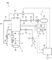
図1及び図2は、本発明の一実施形態による燃料電池10の構成を説明するための図である。図1は燃料電池10の斜視図であり、図2は図1の燃料電池10のII−II断面図である。
1 and 2 are views for explaining the configuration of a
図1及び図2に示すように、燃料電池10は、膜電極接合体(MEA)11と、MEA11を挟むように配置されるアノードセパレータ12及びカソードセパレータ13と、を備える。
As shown in FIGS. 1 and 2, the
MEA11は、電解質膜111と、アノード電極112と、カソード電極113とから構成されている。MEA11は、電解質膜111の一方の面側にアノード電極112を有しており、他方の面側にカソード電極113を有している。
The
電解質膜111は、フッ素系樹脂により形成されたプロトン伝導性のイオン交換膜である。電解質膜111は、適度な湿潤度で良好な電気伝導性を示す。 The electrolyte membrane 111 is a proton-conductive ion exchange membrane formed of a fluorine-based resin. The electrolyte membrane 111 exhibits good electrical conductivity with an appropriate degree of wetness.
アノード電極112は、触媒層112Aとガス拡散層112Bとを備える。触媒層112Aは、白金又は白金等が担持されたカーボンブラック粒子により形成された部材であって、電解質膜111と接するように設けられる。ガス拡散層112Bは、触媒層112Aの外側に配置される。ガス拡散層112Bは、ガス拡散性及び導電性を有するカーボンクロスで形成された部材であって、触媒層112A及びアノードセパレータ12と接するように設けられる。
The
アノード電極112と同様に、カソード電極113も触媒層113Aとガス拡散層113Bとを備える。触媒層113Aは電解質膜111とガス拡散層113Bとの間に配置され、ガス拡散層113Bは触媒層113Aとカソードセパレータ13との間に配置される。
Similar to the
アノードセパレータ12は、ガス拡散層112Bの外側に配置される。アノードセパレータ12は、アノード電極112にアノードガス(水素ガス)を供給するための複数のアノードガス流路121を備えている。アノードガス流路121は、溝状通路として形成されている。
The
カソードセパレータ13は、ガス拡散層113Bの外側に配置される。カソードセパレータ13は、カソード電極113にカソードガス(空気)を供給するための複数のカソードガス流路131を備えている。カソードガス流路131は、溝状通路として形成されている。
The
図2に示すように、アノードセパレータ12及びカソードセパレータ13は、アノードガス流路121を流れるアノードガスの流れ方向とカソードガス流路131を流れるカソードガスの流れ方向とが互いに逆向きとなるように構成されている。なお、アノードセパレータ12及びカソードセパレータ13は、これらガスの流れ方向が同じ向きに流れるように構成されてもよい。
As shown in FIG. 2, the
このような燃料電池10を自動車用電源として使用する場合には、要求される電力が大きいため、数百枚の燃料電池10を積層した燃料電池スタック1が構成される。そして、燃料電池スタック1にアノードガス及びカソードガスを供給する燃料電池システム100を構成して、車両を駆動させるための電力を取り出す。
When such a
図3は、本発明の一実施形態による燃料電池システム100の概略構成図である。
FIG. 3 is a schematic configuration diagram of a
燃料電池システム100は、燃料電池スタック1と、カソードガス給排装置2と、アノードガス給排装置3と、スタック冷却装置4と、電力システム5と、コントローラ60と、を備える。
The
燃料電池スタック1は、複数の燃料電池10を積層した電池である。燃料電池スタック1は、アノードガス及びカソードガスの供給を受けて、車両の走行に必要な電力を発電する。
The
カソードガス給排装置2は、カソードガス供給通路21と、カソードガス排出通路22と、カソードコンプレッサ23と、カソード流量センサ24と、カソード圧力センサ25と、カソード調圧弁26と、を備える。カソードガス給排装置2は、燃料電池スタック1にカソードガスを供給するとともに、燃料電池スタック1から排出されるカソードオフガスを外部に排出する。
The cathode gas supply / discharge device 2 includes a cathode
カソードガス供給通路21は、燃料電池スタック1に供給されるカソードガスが流れる通路である。カソードガス供給通路21の一端はカソードコンプレッサ23に接続され、他端は燃料電池スタック1のカソードガス入口部に接続される。
The cathode
カソードガス排出通路22は、燃料電池スタック1から排出されるカソードオフガスが流れる通路である。カソードガス排出通路22の一端は燃料電池スタック1のカソードガス出口部に接続され、他端は開口端として形成される。カソードオフガスは、カソードガスや電極反応によって生じた水蒸気等を含む混合ガスである。
The cathode
カソードコンプレッサ23は、カソードガス供給通路21の先端に設けられる。カソードコンプレッサ23は、カソードガスとしての空気を取り込み、燃料電池スタック1にカソードガスを供給する。
The
カソード流量センサ24は、カソードコンプレッサ23よりも下流のカソードガス供給通路21に設けられる。カソード流量センサ24は、燃料電池スタック1に供給されるカソードガスの流量を検出する。
The cathode
カソード圧力センサ25は、カソード流量センサ24よりも下流のカソードガス供給通路21に設けられる。カソード圧力センサ25は、燃料電池スタック1のカソードガス入口部の近傍に配置される。カソード圧力センサ25は、燃料電池スタック1に供給されるカソードガスの圧力を検出する。カソード圧力センサ25で検出されたカソードガス圧力は、燃料電池スタック1のカソードガス流路131等を含むカソード系全体の圧力を代表する。
The
カソード調圧弁26は、カソードガス排出通路22に設けられる。カソード調圧弁26は、コントローラ60によって開閉制御され、燃料電池スタック1に供給されるカソードガスの圧力を調整する。
The cathode
次に、アノードガス給排装置3について説明する。
Next, the anode gas supply /
アノードガス給排装置3は、燃料電池スタック1にアノードガスを供給するとともに、燃料電池スタック1から排出されるアノードオフガスをカソードガス排出通路22に排出する。アノードガス給排装置3は、高圧タンク31と、アノードガス供給通路32と、アノード調圧弁33と、アノード流量センサ34と、アノード圧力センサ35と、アノードガス排出通路36と、パージ弁37と、を備える。さらに、アノードガス給排装置3は、アノードガス供給通路32とアノードガス排出通路36とを接続する還流通路38、及び還流通路38に設置される還流ポンプ39を備えている。
The anode gas supply /
高圧タンク31は、燃料電池スタック1に供給するアノードガスを高圧状態に保って貯蔵する容器である。
The high-
アノードガス供給通路32は、高圧タンク31から排出されるアノードガスを燃料電池スタック1に供給する通路である。アノードガス供給通路32の一端は高圧タンク31に接続され、他端は燃料電池スタック1のアノードガス入口部に接続される。
The anode
アノード調圧弁33は、高圧タンク31よりも下流のアノードガス供給通路32に設けられる。アノード調圧弁33は、コントローラ60によって開閉制御され、燃料電池スタック1に供給されるアノードガスの圧力を調整する。
The anode
アノードガス排出通路36は、燃料電池スタック1から排出されたアノードオフガスを流す通路である。アノードガス排出通路36の一端は燃料電池スタック1のアノードガス出口部に接続され、他端はカソード調圧弁26よりも下流のカソードガス排出通路22に接続される。
The anode
パージ弁37は、アノードガス排出通路36に設けられる。パージ弁37は、コントローラ60によって開閉制御され、アノードガス排出通路36からカソードガス排出通路22に排出するアノードオフガスのパージ流量を制御する。
The
パージ弁37が開弁状態となるパージ制御が実行されると、アノードオフガスは、アノードガス排出通路36及びカソードガス排出通路22を通じて外部に排出される。この時、アノードオフガスは、カソードガス排出通路22内でカソードオフガスと混合される。このようにアノードオフガスとカソードオフガスとを混合させて外部に排出することで、混合ガス中の水素濃度が排出許容濃度以下の値に設定される。
When purge control is performed to open the
還流通路38は、アノードガス排出通路36のアノードオフガスをアノードガス供給通路32に流す通路である。還流通路38の一端はアノードガス出口部とパージ弁37との間のアノードガス排出通路36に接続され、還流通路38の他端はアノードガス入口部とアノード調圧弁33との間のアノードガス供給通路32に接続される。
The
還流通路38には、還流ポンプ39が設けられる。還流ポンプ39は、燃料電池スタック1から排出されたアノードオフガスを還流通路38を通じてアノードガス供給通路32に還流する。このように、還流通路38及び還流ポンプ39は、燃料電池スタック1から排出されたアノードオフガスを再び燃料電池スタック1に供給する循環機構を構成する。
A
アノード流量センサ34は、還流通路38の接続部よりも下流のアノードガス供給通路32に設けられる。アノード流量センサ34は、燃料電池スタック1に供給されるアノードガスの循環流量を検出する。
The anode
アノード圧力センサ35は、アノード流量センサ34よりも下流のアノードガス供給通路32に設けられる。アノード圧力センサ35は、燃料電池スタック1に供給されるアノードガスの圧力を検出する。アノード圧力センサ35で検出されたアノードガス圧力は、燃料電池スタック1のアノードガス流路121等を含むアノード系全体の圧力を代表する。
The
スタック冷却装置4は、不凍液等である冷却水によって燃料電池スタック1を冷却し、燃料電池スタック1を発電に適した温度に調整する温度調整装置である。スタック冷却装置4は、循環通路41と、ラジエータ42と、バイパス通路43と、三方弁44と、循環ポンプ45と、入口水温センサ46と、出口水温センサ47と、を備える。
The
循環通路41は、冷却水が循環するループ状通路を構成する。循環通路41の一端は燃料電池スタック1の冷却水入口部に接続され、他端は燃料電池スタック1の冷却水出口部に接続される。
The
ラジエータ42は、循環通路41に設けられる。ラジエータ42は、燃料電池スタック1から排出された冷却水の熱を外部に放熱する熱交換器である。
The
バイパス通路43は、ラジエータ42をバイパスさせて冷却水を流す通路である。バイパス通路43の一端はラジエータ42より上流の循環通路41に接続され、他端はラジエータ42より下流の循環通路41に設けられた三方弁44に接続される。
The
三方弁44は、冷却水の温度に応じて冷却水の循環経路を切り替える。具体的には、冷却水温度が所定温度よりも高い場合、三方弁44は燃料電池スタック1から排出された冷却水がラジエータ42を通じて再び燃料電池スタック1に供給されるように切り換えられる。これに対して、冷却水温度が所定温度よりも低い場合、三方弁44は燃料電池スタック1から排出された冷却水がバイパス通路43を流れて再び燃料電池スタック1に供給されるように切り換えられる。
The three-
循環ポンプ45は、三方弁44よりも下流の循環通路41に設けられ、冷却水を循環させる。
The
入口水温センサ46は燃料電池スタック1の冷却水入口部近傍の循環通路41に設けられ、出口水温センサ47は燃料電池スタック1の冷却水出口部近傍の循環通路41に設けられる。入口水温センサ46は燃料電池スタック1に流入する冷却水の温度を検出し、出口水温センサ47は燃料電池スタック1から排出された冷却水の温度を検出する。入口水温センサ46によって検出された入口水温と出口水温センサ47によって検出された出口水温とから算出される平均水温が、燃料電池スタック1の内部温度、いわゆるスタック温度となる。
The inlet
電力システム5は、電流センサ51と、電圧センサ52と、走行モータ53と、インバータ54と、バッテリ55と、DC/DCコンバータ56と、を備える。
The power system 5 includes a
電流センサ51は、燃料電池スタック1から取り出される出力電流を検出する。電圧センサ52は、燃料電池スタック1の出力電圧、つまり燃料電池スタック1の端子間電圧を検出する。
The
走行モータ53は、三相交流同期モータであって、車輪を駆動するための駆動源である。走行モータ53は、燃料電池スタック1及びバッテリ55から電力の供給を受けて回転駆動する電動機としての機能と、外力によって回転駆動されることで発電する発電機としての機能とを有する。
The traveling
インバータ54は、IGBT等の複数の半導体スイッチから構成される。インバータ54の半導体スイッチは、コントローラ60によってスイッチング制御され、これにより直流電力が交流電力に、又は交流電力が直流電力に変換される。走行モータ53を電動機として機能させる場合、インバータ54は、燃料電池スタック1の出力電力とバッテリ55の出力電力との合成直流電力を三相交流電力に変換し、走行モータ53に供給する。これに対して、走行モータ53を発電機として機能させる場合、インバータ54は、走行モータ53の回生交流電力を直流電力に変換し、バッテリ55に供給する。
The
バッテリ55は、燃料電池スタック1の出力電力の余剰分及び走行モータ53の回生電力が充電されるように構成されている。バッテリ55に充電された電力は、必要に応じてカソードコンプレッサ23等の補機類や走行モータ53に供給される。
The
DC/DCコンバータ56は、燃料電池スタック1の出力電圧を昇降圧させる双方向性の電圧変換機である。DC/DCコンバータ56によって燃料電池スタック1の出力電圧を制御することで、燃料電池スタック1の出力電流等が調整される。
The DC /
コントローラ60は、中央演算装置(CPU)、読み出し専用メモリ(ROM)、ランダムアクセスメモリ(RAM)及び入出力インタフェース(I/Oインタフェース)を備えたマイクロコンピュータで構成される。コントローラ60には、カソード流量センサ24やアノード流量センサ34等の各種センサからの信号の他、アクセルペダルの踏み込み量を検出するアクセルストロークセンサ7等の車両運転状態を検出するセンサからの信号が入力される。
The
コントローラ60は、燃料電池システム100の運転状態に応じて、アノード調圧弁33及び還流ポンプ39を制御することでアノードガスの圧力及び循環流量を調整するとともに、カソード調圧弁26及びカソードコンプレッサ23を制御することでカソードガスの圧力及び流量を調整する。
The
また、コントローラ60は、燃料電池システム100の運転状態に基づいて、燃料電池スタック1の目標出力電力を算出する。コントローラ60は、走行モータ53の要求電力や補機類の要求電力、バッテリ55の充放電要求等に基づいて、目標出力電力を算出する。コントローラ60は、目標出力電力に基づいて、予め定められた燃料電池スタック1の電流電圧特性を参照し、燃料電池スタック1の目標出力電流を算出する。そして、コントローラ60は、DC/DCコンバータ56を用いて、燃料電池スタック1の出力電流が目標出力電流となるように燃料電池スタック1の出力電圧を制御する。
Further, the
上記した燃料電池システム100の燃料電池スタック1では、各燃料電池10の電解質膜111の湿潤度(含水量)が高くなり過ぎたり低くなり過ぎたりすると、発電性能が低下する。燃料電池スタック1を効率的に発電させるためには、燃料電池スタック1の電解質膜111を適度な湿潤度に維持することが重要である。そのため、燃料電池システム100では、燃料電池スタック1の湿潤状態が発電に適した状態となるように、カソードガス流量及びアノードガス循環流量が制御される。
In the
カソードガス流量制御は主にカソードコンプレッサ23により実行され、カソードコンプレッサ23は目標カソードガス流量に応じてカソードガス流量を制御するカソードガス流量制御部として機能する。また、アノードガス循環流量制御は主に還流ポンプ39により実行され、還流ポンプ39は目標アノードガス循環流量に応じてアノードガス循環流量を制御するアノードガス流量制御部として機能する。
The cathode gas flow rate control is mainly executed by the
例えば、カソードガス流量を増加させる場合には、カソードガスとともに燃料電池スタック1から排出される水分が増えるため、電解質膜111の湿潤度が低下する。これにより、燃料電池スタック1の湿潤度をドライ側に調整することができる。これに対して、カソードガス流量を減少させる場合には、カソードガスとともに燃料電池スタック1から排出される水分が減るため、電解質膜111の湿潤度が増加する。これにより、燃料電池スタック1の湿潤度をウェット側に調整することができる。
For example, when the cathode gas flow rate is increased, the moisture discharged from the
一方、アノードガスは、カソードガス流路131(図2参照)の下流側から電解質膜111を介してリークしてきた水分によって加湿される。このように加湿されるアノードガスの循環流量を増加させると、アノードガスに含まれる水分がアノードガス流路121(図2参照)の上流から下流まで行き渡りやすくなり、燃料電池スタック1の電解質膜111の湿潤度を高めることができる。これにより、燃料電池スタック1の湿潤度をウェット側に調整することができる。これに対して、アノードガス循環流量を減少させる場合には、電解質膜111の湿潤度が低下する。これにより、燃料電池スタック1の湿潤度をドライ側に調整することができる。
On the other hand, the anode gas is humidified by moisture leaked through the electrolyte membrane 111 from the downstream side of the cathode gas channel 131 (see FIG. 2). When the circulation flow rate of the humidified anode gas is increased in this way, the moisture contained in the anode gas easily spreads from the upstream to the downstream of the anode gas flow path 121 (see FIG. 2), and the electrolyte membrane 111 of the
なお、燃料電池システム100は、カソードガス流量及びアノードガス循環流量を制御するだけでなく、カソードガス圧力や冷却水温度等を制御することで、燃料電池スタック1の湿潤度を調整するように構成されてもよい。
The
ところで、本願発明者らは、燃料電池スタック1の湿潤制御に関し、カソードガス流量が多い場合にアノードガス循環流量を変更しても、アノードガス循環流量制御によって燃料電池スタック1の湿潤度をほとんど調整することができないことを見出した。
By the way, the inventors of the present application relate to the wet control of the
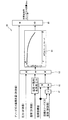
図4は、アノードガスとカソードガスの流量比と、燃料電池スタック1から排出されるカソードガスの相対湿度との関係を示す特性図である。カソードガス相対湿度は、燃料電池スタック1から排出されるカソードガスに含まれる水分量を示す指標である。カソードガス相対湿度が低くなるほど、燃料電池スタック1の電解質膜111はウェットな状態となる。本願発明者らは、カソードガス相対湿度と、アノードガス流量(循環流量)をカソードガス流量で除算して得られる流量比との間に、図4に示すような関係があることを見出した。
FIG. 4 is a characteristic diagram showing the relationship between the flow rate ratio between the anode gas and the cathode gas and the relative humidity of the cathode gas discharged from the
つまり、アノードガス循環流量制御に基づいて湿潤制御を実行する場合、アノードガス循環流量が小さく、流量比が小さい領域(破線領域)では、カソードガス相対湿度はほとんど変化せず、燃料電池スタック1の湿潤度をほとんど調整することができない。これに対して、流量比が大きい領域では、流量比に応じてカソードガス相対湿度を変更することができ、燃料電池スタック1の湿潤度を調整することが可能となる。本願発明者らが見出した知見によれば、アノードガス循環流量を制御して燃料電池スタック1の湿潤度を調整する場合には、例えばカソードガス流量をできる限り少なく抑えて、流量比を大きく設定する必要がある。
That is, when the wet control is executed based on the anode gas circulation flow control, the cathode gas relative humidity hardly changes in the region where the anode gas circulation flow rate is small and the flow rate ratio is small (broken line region). The wetness can hardly be adjusted. On the other hand, in the region where the flow rate ratio is large, the cathode gas relative humidity can be changed according to the flow rate ratio, and the wetness of the
そこで、燃料電池システム100は、上述した知見に基づき、アノードガス循環流量及びカソードガス流量の制御によって燃料電池スタック1の湿潤度を適切に制御できるように構成されている。
Therefore, the
アノードガス循環流量及びカソードガス流量の制御は、燃料電池スタック1の運転状態に応じてコントローラ60が算出した目標アノードガス循環流量及び目標カソードガス流量に基づいて実行される。そして、還流ポンプ39が目標アノードガス循環流量に応じて燃料電池スタック1に供給されるアノードガスの流量を制御し、カソードコンプレッサ23が目標カソードガス流量に応じて燃料電池スタック1に供給されるカソードガスの流量を制御する。
The control of the anode gas circulation flow rate and the cathode gas flow rate is executed based on the target anode gas circulation flow rate and the target cathode gas flow rate calculated by the
次に、図5を参照して、コントローラ60が実行するガス流量算出処理について説明する。図5は、燃料電池システム100に備えられるコントローラ60の構成を示すブロック図である。
Next, a gas flow rate calculation process executed by the
図5に示すように、コントローラ60は、燃料電池スタック1の湿潤状態の目標値である湿潤目標値を算出する湿潤目標値算出部61と、燃料電池スタック1に対する発電要求に基づいてカソードガス要求流量及びアノードガス要求循環流量を算出するガス要求流量算出部63と、湿潤目標値やこれら要求流量に基づいて目標アノードガス流量及び目標カソードガス流量を算出するガス流量算出部62と、を備える。
As shown in FIG. 5, the
湿潤目標値算出部61は、基本湿潤値算出部61Aと、減算部61Bと、PI制御実行部61Cと、加算部61Dとから構成されている。
The wet target
基本湿潤値算出部61Aは、燃料電池スタック1の内部インピーダンス(HFR)の目標値に基づいて基本湿潤値を算出する。基本湿潤値は、HFR目標値が大きくなるほど小さな値に設定される。
The basic
なお、燃料電池スタック1の内部インピーダンス(HFR)と燃料電池スタック1の電解質膜111の湿潤度との間には相関関係がある。燃料電池スタック1の内部インピーダンスは、湿潤度が低下するほど、つまり電解質膜111が乾燥するほど大きな値となる。HFR目標値は、燃料電池スタック1の発電負荷が大きくなるほど小さな値に設定される。また、HFR目標値は、燃料電池スタック1の発電負荷が同一である場合にスタック温度が高くなるほど小さな値となるように補正される。
Note that there is a correlation between the internal impedance (HFR) of the
減算部61Bは、HFR目標値から、燃料電池スタック1の内部インピーダンスの計測値を減算し、HFR目標値とHFR計測値との差分(HFR偏差)を算出する。HFR計測値は、電流センサ51により検出される燃料電池スタック1の出力電流及び電圧センサ52により検出される燃料電池スタック1の出力電圧に基づいて算出される。
The subtractor 61B subtracts the measured value of the internal impedance of the
PI制御実行部61Cは、減算部61Bで算出されたHFR偏差に基づいてフィードバック補正値を算出する。
The PI
加算部61Dは、基本湿潤値とフィードバック補正値とを加算して、湿潤目標値を算出する。湿潤目標値は燃料電池スタック1の湿潤度の目標値に相当するものであり、この湿潤目標値に応じて燃料電池スタック1の湿潤制御が実行される。
The adding
このように、湿潤目標値算出部61は、HFR目標値及びHFR計測値に基づいて湿潤目標値を算出するように構成されている。湿潤目標値算出部61による湿潤目標値の算出方法は一例であり、その他の手法を用いて湿潤目標値を算出してもよい。
As described above, the wet target
ガス要求流量算出部63は、燃料電池スタック1に対する発電要求に基づいてカソードガス要求流量Qc(図8参照)及びアノードガス要求循環流量Qa(図9参照)を算出する。
The required gas flow
ガス流量算出部62は、これら要求流量や湿潤目標値算出部61により算出された湿潤目標値に基づいて、目標アノードガス循環流量及び目標カソードガス流量を算出する。ガス流量算出部62は、燃料電池スタック1の湿潤度が運転状態に適した状態となるように、目標アノードガス循環流量及び目標カソードガス流量を演算する。
The gas flow
次に、図6から図10を参照して、コントローラ60のガス流量算出部62が実行するドライ制御時の目標アノードガス循環流量及び目標カソードガス流量の算出処理について説明する。
Next, the calculation processing of the target anode gas circulation flow rate and the target cathode gas flow rate during dry control performed by the gas flow
図6は、ドライ制御時におけるガス流量算出部62での目標アノードガス循環流量及び目標カソードガス流量の算出処理を示す図である。図7は、湿潤制御用アノードガス流量算出部70での算出処理を示す図である。図8は、燃料電池スタック1に対する発電要求に基づくカソードガス要求流量Qcの特性図である。図9は、燃料電池スタック1に対する発電要求に基づくアノードガス要求循環流量Qaの特性図である。図10は、湿潤制御用カソードガス流量算出部80での算出処理を示す図である。
FIG. 6 is a diagram showing calculation processing of the target anode gas circulation flow rate and the target cathode gas flow rate in the gas flow
図6に示すように、コントローラ60のガス流量算出部62は、湿潤制御用アノードガス流量算出部70と、目標アノードガス流量設定部91と、湿潤制御用カソードガス流量算出部80と、目標カソードガス流量設定部92と、から構成されている。
As shown in FIG. 6, the gas flow
燃料電池スタック1の湿潤度を低下させるドライ制御時には、湿潤制御用アノードガス流量算出部70は、湿潤目標値算出部61により算出された湿潤目標値と、カソードガス圧力の計測値と、冷却水温度の計測値と、カソードガス要求流量Qcとに基づいて、湿潤制御用アノードガス循環流量Qwaを算出する。なお、コントローラ60は、例えば現在の湿潤目標値を前回値と比較することによって、ドライ制御時であるかウェット制御時であるかを判断する。
During dry control for reducing the wetness of the
図7に示すように、湿潤制御用アノードガス流量算出部70は、加算部71と、除算部72、カソードガス相対湿度算出部73と、流量比算出部74と、乗算部75と、を備えている。
As shown in FIG. 7, the wet control anode gas flow
湿潤制御用アノードガス流量算出部70は、加算部71において湿潤目標値と図8から求められるカソードガス要求流量Qcとを加算し、除算部72において湿潤目標値をこの加算値で除することで、カソードガス湿潤状態値を算出する。
The wet control anode gas flow
湿潤制御用アノードガス循環流量Qwaの算出に使用されるカソードガス要求流量Qcは、図8に示す特性図を参照し、車両運転状態に基づいて求められる燃料電池スタック1に対する発電要求、つまり燃料電池スタック1から取り出される発電電流に応じて算出される。
The cathode gas request flow rate Qc used for calculating the wet control anode gas circulation flow rate Qwa refers to the characteristic diagram shown in FIG. 8, and is a power generation request for the
図8に示すように、カソードガス要求流量Qcは、発電電流が0からI1までは一定値となり、I1以上では発電電流の増加に伴って大きな値となる。カソードガス要求流量Qcは、燃料電池スタック1に対する発電要求に応じて規定されており、例えば燃料電池スタック1が正常状態で発電する際に最低限必要なカソードガス流量として規定されている。この正常状態には、燃料電池スタック1の湿潤度が適切な範囲内に制御されている状態のほか、フラッディングの発生が防止されている状態やカソードコンプレッサ23の回転数が最低回転数を下回らない状態等が含まれる。As shown in FIG. 8, the cathode gas required flow rate Qc becomes a constant value when the generated current is from 0 to I 1 , and becomes a large value as the generated current is increased when I 1 or more. The cathode gas required flow rate Qc is defined in accordance with a power generation request to the
湿潤制御用アノードガス流量算出部70のカソードガス相対湿度算出部73は、カソードガス圧力の計測値と、除算部72で算出されたカソードガス湿潤状態値とを乗算し、その乗算値を冷却水温度の計測値から求められる飽和水蒸気圧力で除することで、カソードガス相対湿度を算出する。カソードガス相対湿度は、図4において説明したように、燃料電池スタック1から排出されるカソードガスに含まれる水分量を示す指標である。
The cathode gas relative
なお、カソードガス相対湿度算出部73で使用されるカソードガス圧力の計測値はカソード圧力センサ25の検出値に基づいて算出され、冷却水温度の計測値は入口水温センサ46及び出口水温センサ47の検出値に基づいて算出される。また、カソードガス圧力及び冷却水温度の計測値を使用する代わりに、カソードガス圧力及び冷却水温度の推定値を用いてもよい。
The measured value of the cathode gas pressure used in the cathode gas relative
流量比算出部74は、図4で説明した流量比−カソードガス相対湿度特性マップを参照し、カソードガス相対湿度算出部73で算出されたカソードガス相対湿度に基づき、湿潤制御に必要な流量比を算出する。流量比算出部74で算出される流量比は、カソードガス流量に対するアノードガス循環流量の割合である。
The flow rate
乗算部75は、流量比算出部74で算出された流量比と、加算部71で使用されたカソードガス要求流量Qcとを乗算することで、湿潤制御用アノードガス循環流量Qwaを算出する。
The
なお、湿潤制御用アノードガス流量算出部70は、カソードガス圧力及び冷却水温度を用いずに、湿潤目標値とカソードガス要求流量とからカソードガス相対湿度を算出し、そのカソードガス相対湿度を用いて湿潤制御用アノードガス循環流量を算出するように構成されてもよい。
The wet control anode gas flow
図6に示すように、ガス流量算出部62は、目標アノードガス流量設定部91において、上記のように算出された湿潤制御用アノードガス循環流量Qwaと、燃料電池スタック1に対する発電要求から求められたアノードガス要求循環流量Qaとを比較し、それら流量の大きい方をドライ制御時の目標アノードガス循環流量Qtaに設定する。
As shown in FIG. 6, the gas flow
目標アノードガス循環流量Qtaを設定する際に使用されるアノードガス要求循環流量Qaは、図9に示す特性図を参照し、車両運転状態に基づいて求められる燃料電池スタック1に対する発電要求、つまり燃料電池スタック1から取り出される発電電流に応じて算出される。
The anode gas required circulation flow rate Qa used when setting the target anode gas circulation flow rate Qta is referred to the characteristic diagram shown in FIG. 9, and the power generation request for the
図9に示すように、アノードガス要求循環流量Qaは、発電電流が0からI2までは一定値となり、I2以上では発電電流の増加に伴って大きな値となる。アノードガス要求循環流量Qaは、燃料電池スタック1に対する発電要求に応じて規定されており、例えば燃料電池スタック1が正常状態で発電する際に最低限必要なアノードガス循環流量として規定されている。この正常状態には、燃料電池スタック1の湿潤度が適切な範囲内に制御されている状態のほか、フラッディングの発生が防止されている状態や還流ポンプ39の回転数が最低回転数を下回らない状態等が含まれる。As shown in FIG. 9, the anode gas required circulation flow rate Qa becomes a constant value when the generated current is from 0 to I 2 , and becomes a large value as the generated current increases when I 2 or more. The anode gas required circulation flow rate Qa is defined according to a power generation request for the
一方、ドライ制御時には、湿潤制御用カソードガス流量算出部80は、湿潤目標値算出部61により算出された湿潤目標値と、カソードガス圧力の計測値と、冷却水温度の計測値と、アノードガス循環流量の計測値とに基づいて、湿潤制御用カソードガス流量Qwcを算出する。
On the other hand, at the time of dry control, the wet control cathode gas flow
図10に示すように、湿潤制御用カソードガス流量算出部80は、加算部81と、第一除算部82、カソードガス相対湿度算出部83と、流量比算出部84と、第二除算部85と、を備えている。
As shown in FIG. 10, the wet control cathode gas flow
湿潤制御用カソードガス流量算出部80は、加算部81において湿潤目標値と目標カソードガス流量Qtcの前回値とを加算し、第一除算部82において湿潤目標値をこの加算値で除することで、カソードガス湿潤状態値を算出する。カソードガス湿潤状態値の算出には、目標カソードガス流量Qtcの前回値の代わりに、カソードガス流量の計測値を使用してもよい。
The wet control cathode gas flow
湿潤制御用カソードガス流量算出部80のカソードガス相対湿度算出部83は、カソードガス圧力の計測値と、第一除算部82で算出されたカソードガス湿潤状態値とを乗算し、その乗算値を冷却水温度の計測値から求められる飽和水蒸気圧力で除することで、カソードガス相対湿度を算出する。なお、カソードガス圧力及び冷却水温度の計測値を使用する代わりに、カソードガス圧力及び冷却水温度の推定値を用いてもよい。
The cathode gas relative
流量比算出部84は、図4で説明した流量比−カソードガス相対湿度特性マップを参照し、カソードガス相対湿度算出部83で算出されたカソードガス相対湿度に基づき、湿潤制御に必要な流量比を算出する。流量比算出部84で算出される流量比は、カソードガス流量に対するアノードガス循環流量の割合である。
The flow rate
第二除算部85は、アノードガス循環流量の計測値を流量比算出部84で算出された流量比で除することで、湿潤制御用カソードガス流量Qwcを算出する。なお、アノードガス循環流量の計測値は、アノード流量センサ34の検出値に基づいて算出される。また、アノードガス循環流量の計測値ではなく、アノードガス循環流量の推定値を用いてもよい。
The
なお、湿潤制御用カソードガス流量算出部80は、カソードガス圧力及び冷却水温度を用いずに、湿潤目標値と目標カソードガス流量Qtcの前回値又はカソードガス流量の計測値(推定値)とからカソードガス相対湿度を算出し、そのカソードガス相対湿度を用いて湿潤制御用カソードガス流量を算出するように構成されてもよい。
The wet control cathode gas flow
図6に示すように、ガス流量算出部62は、目標カソードガス流量設定部92において、上記のように算出された湿潤制御用カソードガス流量Qwcと、燃料電池スタック1に対する発電要求から求められたカソードガス要求流量Qc(図8参照)とを比較し、それら流量の大きい方をドライ制御時の目標カソードガス流量Qtcに設定する。
As shown in FIG. 6, the gas flow
このように、ガス流量算出部62では、ドライ制御時の湿潤制御用アノードガス循環流量Qwaは、少なくとも湿潤目標値と、燃料電池スタック1が正常状態で発電する際に必要なカソードガス要求流量Qcとに基づいて算出される。一方、ドライ制御時の湿潤制御用カソードガス流量Qwcは、少なくとも湿潤目標値と、アノードガス循環流量の計測値又は推定値とに基づいて算出される。つまり、ドライ制御時における湿潤制御用アノードガス循環流量及び湿潤制御用カソードガス流量は、アノードガス循環流量制御に基づいて湿潤度をドライ側に制御できない場合に、ドライ制御の不足分をカソードガス流量制御により補うように算出される。このように両ガス流量を算出することで、図14を参照して後述するように、カソードガス流量制御によるドライ制御よりもアノードガス循環流量制御によるドライ制御に優位性を持たせることが可能となる。
Thus, in the gas flow
次に、図11〜図13を参照して、コントローラ60のガス流量算出部62が実行するウェット制御時の目標アノードガス循環流量及び目標カソードガス流量の算出処理について説明する。
Next, the calculation processing of the target anode gas circulation flow rate and the target cathode gas flow rate during wet control performed by the gas flow
図11は、ウェット制御時におけるガス流量算出部62での目標アノードガス循環流量及び目標カソードガス流量の算出処理を示す図である。図12は、湿潤制御用アノードガス流量算出部70での算出処理を示す図である。図13は、湿潤制御用カソードガス流量算出部80での算出処理を示す図である。
FIG. 11 is a diagram illustrating calculation processing of the target anode gas circulation flow rate and the target cathode gas flow rate in the gas flow
図11及び図12に示すように、燃料電池スタック1の湿潤度を増加させるウェット制御時には、ガス流量算出部62の湿潤制御用アノードガス流量算出部70は、湿潤目標値と、カソードガス圧力の計測値と、冷却水温度の計測値と、カソードガス流量の計測値とに基づいて、湿潤制御用アノードガス循環流量Qwaを算出する。図12に示す湿潤制御用アノードガス流量算出部70での各算出処理は、カソードガス要求流量Qcの代わりにカソードガス流量の計測値を用いる点以外は、図7に示した算出処理と同様である。このように、湿潤制御用アノードガス流量算出部70は、ドライ制御時にはカソードガス要求流量Qcを用いて湿潤制御用アノードガス循環流量Qwaを算出するのに対し、ウェット制御時にはカソードガス流量の計測値を用いて湿潤制御用アノードガス循環流量Qwaを算出する。
As shown in FIGS. 11 and 12, during wet control for increasing the wetness of the
なお、ウェット制御時の湿潤制御用アノードガス循環流量の算出では、カソードガス圧力、冷却水温度、及びカソードガス流量の計測値を使用する代わりに、カソードガス圧力、冷却水温度、及びカソードガス流量の推定値を用いてもよい。湿潤制御用アノードガス流量算出部70は、カソードガス圧力及び冷却水温度を用いずに、湿潤目標値と燃料電池スタック1に供給されるカソードガス流量の計測値又は推定値とからカソードガス相対湿度を算出し、そのカソードガス相対湿度を用いて湿潤制御用アノードガス循環流量を算出するように構成されてもよい。
In calculating the wet control anode gas circulation flow rate during wet control, instead of using the measured values of the cathode gas pressure, cooling water temperature, and cathode gas flow rate, the cathode gas pressure, cooling water temperature, and cathode gas flow rate are used. The estimated value may be used. The wet control anode gas flow
図11に示すように、ガス流量算出部62は、目標アノードガス流量設定部91において、上記のように算出された湿潤制御用アノードガス循環流量Qwaと、燃料電池スタック1に対する発電要求から求められたアノードガス要求循環流量Qa(図9参照)とを比較し、それら流量の大きい方をウェット制御時の目標アノードガス循環流量Qtaに設定する。
As shown in FIG. 11, the gas flow
一方、図11及び図13に示すように、ウェット制御時には、湿潤制御用カソードガス流量算出部80は、湿潤目標値と、カソードガス圧力の計測値と、冷却水温度の計測値と、燃料電池スタック1に対する発電要求から求められたアノードガス要求循環流量Qa(図9参照)とに基づいて、湿潤制御用カソードガス流量Qwcを算出する。図13に示す湿潤制御用カソードガス流量算出部80での各算出処理は、アノードガス循環流量の計測値の代わりにアノードガス要求循環流量Qaを用いる点以外は、図10に示した算出処理と同様である。このように、湿潤制御用カソードガス流量算出部80は、ドライ制御時にはアノードガス循環流量の計測値を用いて湿潤制御用カソードガス流量Qwcを算出するのに対し、ウェット制御時にはアノードガス要求循環流量Qaを用いて湿潤制御用カソードガス流量Qwcを算出する。
On the other hand, as shown in FIGS. 11 and 13, during wet control, the wet control cathode gas flow
なお、ウェット制御時の湿潤制御用カソードガス流量の算出では、カソードガス圧力及び冷却水温度の計測値を使用する代わりに、カソードガス圧力及び冷却水温度の推定値を用いてもよい。 In the calculation of the wet control cathode gas flow rate during wet control, estimated values of the cathode gas pressure and the cooling water temperature may be used instead of using the measured values of the cathode gas pressure and the cooling water temperature.
図11に示すように、ガス流量算出部62は、目標カソードガス流量設定部92において、上記のように算出された湿潤制御用カソードガス流量Qwcと、燃料電池スタック1に対する発電要求から求められたカソードガス要求流量Qc(図8参照)とを比較し、それら流量の大きい方をウェット制御時の目標カソードガス流量Qtcに設定する。
As shown in FIG. 11, the gas flow
このように、ガス流量算出部62では、ウェット制御時の湿潤制御用カソードガス流量Qwcは、少なくとも湿潤目標値と、燃料電池スタック1が正常状態で発電する際に必要なアノードガス要求循環流量Qaとに基づいて算出される。一方、ウェット制御時の湿潤制御用アノードガス循環流量Qwaは、少なくとも湿潤目標値と、カソードガス流量の計測値又は推定値とに基づいて算出される。つまり、ウェット制御時における湿潤制御用アノードガス循環流量及び湿潤制御用カソードガス流量は、カソードガス流量制御に基づいて湿潤度をウェット側に制御できない場合に、ウェット制御の不足分をアノードガス循環流量制御により補うように算出される。このように両ガス流量を算出することで、図14を参照して後述するように、アノードガス循環流量制御によるウェット制御よりもカソードガス流量制御によるウェット制御に優位性を持たせることが可能となる。
Thus, in the gas flow
次に、図14を参照して本実施形態による燃料電池システム100での湿潤制御について説明するとともに、図15を参照して参考例による燃料電池システムでの湿潤制御について説明する。
Next, wetting control in the
図15に示すように、参考例による燃料電池システムでは、時刻t0〜t2までの間、湿潤目標値に応じてウェット制御が実行される。 As shown in FIG. 15, in the fuel cell system according to the reference example, the wet control is executed according to the wet target value from time t0 to time t2.
時刻t0〜t1では、カソードガス流量が多い状態のままアノードガス循環流量を増加させるため(流量比が小さくなるため)、アノードガス循環流量を増加させても湿潤度をウェット側に制御することができない。したがって、HFR計測値(破線)はほとんど減少せず、HFR目標値(実線)から大きくずれている。時刻t1以降にカソードガス流量が低下することで、HFR計測値がHFR目標値に向かって収束する。このように、カソードガス流量が多い状態ではアノードガス循環流量を増加させても、効果的にウェット制御を実行することができない。 At times t0 to t1, the anode gas circulation flow rate is increased while the cathode gas flow rate is high (because the flow rate ratio is small), so that the wetness can be controlled to the wet side even if the anode gas circulation flow rate is increased. Can not. Therefore, the HFR measurement value (broken line) hardly decreases and deviates greatly from the HFR target value (solid line). Since the cathode gas flow rate decreases after time t1, the HFR measurement value converges toward the HFR target value. As described above, in a state where the cathode gas flow rate is large, even if the anode gas circulation flow rate is increased, the wet control cannot be effectively performed.
また、参考例による燃料電池システムでは、時刻t3〜t5までの間、湿潤目標値に応じてドライ制御が実行される。 Further, in the fuel cell system according to the reference example, the dry control is executed according to the wet target value from time t3 to time t5.
時刻t3〜t4では、カソードガス流量が増大されることでドライ制御が実行され、HFR計測値(破線)はHFR目標値(実線)に追従する。しかしながら、時刻t4〜t5においては、カソードガス流量が多い状態でアノードガス循環流量を低下させるため(流量比が小さくなるため)、アノードガス循環流量を低下させても湿潤度をドライ側に制御することができない。したがって、HFR計測値は、ほとんど増加せずにHFR目標値からずれ始める。このように、カソードガス流量が多い状態ではアノードガス循環流量を低下させても、効果的にドライ制御を実行することができない。 From time t3 to t4, dry control is executed by increasing the cathode gas flow rate, and the HFR measurement value (broken line) follows the HFR target value (solid line). However, from time t4 to time t5, the anode gas circulation flow rate is lowered with a large cathode gas flow rate (because the flow rate ratio is small), so that the wetness is controlled to the dry side even if the anode gas circulation flow rate is lowered. I can't. Therefore, the HFR measurement value starts to deviate from the HFR target value with little increase. As described above, in a state where the cathode gas flow rate is large, even if the anode gas circulation flow rate is decreased, the dry control cannot be executed effectively.
一方、図14に示すように、燃料電池システム100では、時刻t0〜t2までの間、湿潤目標値に応じてウェット制御が実行される。
On the other hand, as shown in FIG. 14, in the
ウェット制御時には、湿潤制御用カソードガス流量Qwcは、少なくとも湿潤目標値と、燃料電池スタック1が正常状態で発電する際に必要なアノードガス要求循環流量Qaとに基づいて算出され、湿潤制御用アノードガス循環流量Qwaは少なくとも湿潤目標値とカソードガス流量の計測値とに基づいて算出される。つまり、ウェット制御時における湿潤制御用アノードガス循環流量及び湿潤制御用カソードガス流量は、カソードガス流量制御によるウェット制御の不足分をアノードガス循環流量制御により補うように算出される。これら湿潤制御用カソードガス流量Qwc及び湿潤制御用アノードガス循環流量Qwaを利用して目標カソードガス流量及び目標アノードガス循環流量を設定することで、カソードガス流量制御によるウェット制御がアノードガス循環流量制御によるウェット制御よりも優位的に機能する。これにより、カソードガス流量の減少によるウェット制御が実行可能である限り、アノードガス循環流量の増大によるウェット制御の実行が抑制される。
During wet control, the wet control cathode gas flow rate Qwc is calculated based on at least the wet target value and the anode gas required circulation flow rate Qa required when the
したがって、時刻t0〜t1までの間は、アノードガス循環流量が低流量を維持したままカソードガス流量が減少され、カソードガス流量制御によるウェット制御が先行して実行される。カソードガス流量の減少制御だけではウェット制御を実行できなくなる時刻t1以降においては、アノードガス循環流量が増大され、アノードガス循環流量制御によるウェット制御が実行される。この時、カソードガス流量は低く抑えられており、カソードガス流量に対するアノードガス循環流量の比は大きくなっているので、アノードガス循環流量の増大制御により燃料電池スタック1の電解質膜111を加湿することが可能となる。これにより、HFR計測値は、t1以降もHFR目標値に対してずれることなく追従する。
Therefore, during the period from time t0 to t1, the cathode gas flow rate is decreased while the anode gas circulation flow rate is maintained at a low flow rate, and the wet control based on the cathode gas flow rate control is executed in advance. After the time t1 when the wet control cannot be executed only by the decrease control of the cathode gas flow rate, the anode gas circulation flow rate is increased and the wet control by the anode gas circulation flow rate control is executed. At this time, the cathode gas flow rate is kept low, and the ratio of the anode gas circulation flow rate to the cathode gas flow rate is large. Therefore, the electrolyte membrane 111 of the
なお、HFRは燃料電池スタック1の電解質膜111がウェットになるほど変化しにくくなる傾向を有しているため、時刻t1〜t2でのHFRの変化量は時刻t0〜t1でのHFRの変化量と比較して小さい。
Since the HFR tends to change less easily as the electrolyte membrane 111 of the
このように、燃料電池システム100は、カソードガス流量制御に基づいて湿潤度をウェット側に制御できない場合にウェット制御の不足分をアノードガス循環流量制御により補うように構成されている。したがって、燃料電池システム100によれば、アノードガス循環流量やカソードガス流量を無駄に制御することなく、燃料電池スタック1の湿潤度を適切にウェット側に調整することが可能となる。
Thus, the
また、燃料電池システム100では、時刻t3〜t5までの間、湿潤目標値に応じてドライ制御が実行される。
Further, in the
ドライ制御時には、湿潤制御用アノードガス循環流量Qwaは、少なくとも湿潤目標値と、燃料電池スタック1が正常状態で発電する際に必要なカソードガス要求流量Qcとに基づいて算出され、湿潤制御用カソードガス流量Qwcは、少なくとも湿潤目標値と、アノードガス循環流量の計測値とに基づいて算出される。つまり、ドライ制御時における湿潤制御用アノードガス循環流量及び湿潤制御用カソードガス流量は、アノードガス循環流量制御によるドライ制御の不足分をカソードガス流量制御により補うように算出される。これら湿潤制御用カソードガス流量Qwc及び湿潤制御用アノードガス循環流量Qwaを利用して目標カソードガス流量及び目標アノードガス循環流量を設定することで、アノードガス循環流量制御によるドライ制御がカソードガス流量制御によるドライ制御よりも優位的に機能する。これにより、アノードガス循環流量の減少によるドライ制御が実行可能である限り、カソードガス流量の増大によるドライ制御の実行が抑制される。
During dry control, the wet control anode gas circulation flow rate Qwa is calculated based on at least the wet target value and the cathode gas required flow rate Qc required when the
したがって、時刻t3〜t4までの間は、カソードガス流量が低く抑えられた状態でアノードガス循環流量が減少され、アノードガス循環流量制御によるドライ制御が先行して実行される。アノードガス循環流量の減少制御だけではドライ制御を実行できなくなる時刻t4以降においては、カソードガス流量が増大され、カソードガス流量制御によるドライ制御が実行される。このようにアノードガス循環流量の減少制御の後にカソードガス流量の増大制御が実行されるので、これらガス流量制御によって燃料電池スタック1の電解質膜111を適切に乾燥させることができる。これにより、HFR計測値は、HFR目標値に対してずれることなく追従する。
Therefore, between the times t3 and t4, the anode gas circulation flow rate is reduced while the cathode gas flow rate is kept low, and the dry control by the anode gas circulation flow rate control is executed in advance. After the time t4 when the dry control cannot be executed only by the decrease control of the anode gas circulation flow rate, the cathode gas flow rate is increased and the dry control by the cathode gas flow rate control is executed. Thus, since the increase control of the cathode gas flow rate is executed after the decrease control of the anode gas circulation flow rate, the electrolyte membrane 111 of the
このように、燃料電池システム100は、アノードガス循環流量制御に基づいて湿潤度をドライ側に制御できない場合にドライ制御の不足分をカソードガス流量制御により補うように構成されている。したがって、燃料電池システム100によれば、アノードガス循環流量やカソードガス流量を無駄に制御することなく、燃料電池スタック1の湿潤度を適切にドライ側に調整することが可能となる。
Thus, the
図14では、湿潤目標値が緩やかに変化した場合における湿潤制御について説明した。しかしながら、車両の運転状態によっては湿潤目標値が急激に変化する場合がある。以下では、図16を参照して、時刻t6及び時刻t7で湿潤目標値が急増した場合におけるウェット制御について説明する。 In FIG. 14, the wetting control when the wetting target value changes gradually has been described. However, the wet target value may change rapidly depending on the driving state of the vehicle. Below, with reference to FIG. 16, the wet control in the case where the wet target value rapidly increases at time t6 and time t7 will be described.
前述したように燃料電池システム100では、カソードガス流量を調整してウェット制御が実行可能である限り、アノードガス循環流量制御によるウェット制御の実行が抑制されるように、湿潤制御用アノードガス循環流量及び湿潤制御用カソードガス流量は算出される。
As described above, in the
したがって、時刻t6において湿潤目標値が急増した場合には、カソードガス流量が減少制御されるとともに、目標カソードガス流量に対する実際のカソードガス流量の応答遅れ分を補うようにアノードガス循環流量が一時的に増大制御される。このように、カソードガス流量制御だけでは湿潤度をウェット側に調整できない部分が、アノードガス循環流量制御に基づくウェット制御により補われる。その結果、湿潤目標値が急増した場合であっても、HFR目標値(実線)からのHFR計測値(破線)のずれを最小限に抑制することができる。 Therefore, when the wet target value suddenly increases at time t6, the cathode gas flow rate is controlled to decrease, and the anode gas circulation flow rate is temporarily set to compensate for the response delay of the actual cathode gas flow rate with respect to the target cathode gas flow rate. It is controlled to increase. As described above, a portion where the wetness cannot be adjusted to the wet side only by the cathode gas flow rate control is compensated by the wet control based on the anode gas circulation flow rate control. As a result, even when the wet target value increases rapidly, the deviation of the HFR measurement value (broken line) from the HFR target value (solid line) can be suppressed to a minimum.
時刻t6の後、時刻t7において湿潤目標値が急増した場合には、カソードガス流量は既に低流量となっておりそれ以上減少させることができないので、アノードガス循環流量を増大制御することによってウェット制御が実行される。アノードガス循環流量制御によるウェット制御時にはカソードガス流量が低くなっているので、HFR計測値(破線)は僅かな応答遅れを有するもののHFR目標値(実線)に向かって収束していく。 If the wet target value increases rapidly at time t7 after time t6, the cathode gas flow rate is already low and cannot be further reduced. Therefore, wet control is performed by increasing the anode gas circulation flow rate. Is executed. Since the cathode gas flow rate is low during the wet control by the anode gas circulation flow rate control, the HFR measurement value (broken line) converges toward the HFR target value (solid line) although there is a slight response delay.
なお、燃料電池システム100において湿潤目標値が急減する場合には、アノードガス循環流量制御だけでは湿潤度をドライ側に調整できない部分が、カソードガス流量制御に基づくドライ制御により補われる。その結果、湿潤目標値が急減した場合であっても、ドライ制御を効果的に実行することが可能となる。
In the
上記した本実施形態の燃料電池システム100によれば、以下の効果を得ることができる。
According to the
燃料電池システム100は、燃料電池スタック1の湿潤状態の目標値を算出する湿潤目標値算出部61と、燃料電池スタック1に対する発電要求に基づいてカソードガス要求流量を算出するガス要求流量算出部63と、ドライ制御時に少なくとも湿潤目標値とカソードガス要求流量とに基づいて湿潤制御用アノードガス循環流量を算出する湿潤制御用アノードガス流量算出部70と、湿潤制御用アノードガス循環流量に基づいてアノードガス循環流量を制御する還流ポンプ39(アノードガス流量制御部)と、を備える。さらに、燃料電池システム100は、ドライ制御時に少なくとも湿潤目標値とアノードガス循環流量の測定値又は推定値とに基づいて湿潤制御用カソードガス流量を算出する湿潤制御用カソードガス流量算出部80と、カソードガス要求流量と湿潤制御用カソードガス流量に基づいてカソードガス流量を制御するカソードコンプレッサ23(カソードガス流量制御部)と、を備える。このような燃料電池システム100によれば、アノードガス循環流量制御によるドライ制御の不足分をカソードガス流量制御により補うことができ、図14に示したように燃料電池スタック1の湿潤度をドライ側へ適切に制御することができる。
The
一方、ウェット制御時には、ガス要求流量算出部63は、燃料電池スタック1に対する発電要求に基づいてアノードガス要求循環流量を算出し、湿潤制御用カソードガス流量算出部80は、少なくとも湿潤目標値とアノードガス要求循環流量とに基づいて湿潤制御用カソードガス流量を算出する。この時、湿潤制御用アノードガス流量算出部70は、少なくとも湿潤目標値とカソードガス流量の測定値又は推定値とに基づいて湿潤制御用アノードガス循環流量を算出する。このような燃料電池システム100によれば、カソードガス流量制御によるウェット制御の不足分をアノードガス循環流量制御により補うことができ、図14に示したように燃料電池スタック1の湿潤度をウェット側へ適切に制御することができる。
On the other hand, during wet control, the required gas flow
上述の通り、燃料電池システム100によれば燃料電池スタック1の湿潤制御を適切に実行できるため、アノードガス循環流量やカソードガス流量を無駄に制御することがない。したがって、湿潤制御の際に還流ポンプ39やカソードコンプレッサ23を効率的に作動させることができ、燃料電池システム100における電力消費性能を改善することが可能となる。
As described above, according to the
燃料電池システム100を上記とは異なる視点で見た場合、燃料電池システム100は、目標アノードガス循環流量に応じてアノードガス循環流量を制御する還流ポンプ39と、目標カソードガス流量に応じてカソードガス流量を制御するカソードコンプレッサ23と、を備える。また、燃料電池システム100は、燃料電池スタック1の湿潤状態の目標値を算出する湿潤目標値算出部61と、燃料電池スタック1に対する発電要求に基づいてカソードガス要求流量及びアノードガス要求循環流量を算出するガス要求流量算出部63と、を備える。さらに、燃料電池システム100は、ドライ制御時に少なくとも湿潤目標値とアノードガス循環流量の測定値又は推定値とに基づいて湿潤制御用カソードガス流量を算出する湿潤制御用カソードガス流量算出部80と、ドライ制御時に少なくとも湿潤目標値とカソードガス要求流量とに基づいて湿潤制御用アノードガス循環流量を算出する湿潤制御用アノードガス流量算出部70と、カソードガス要求流量と湿潤制御用カソードガス流量に基づいて目標カソードガス流量を設定する目標カソードガス流量設定部92と、アノードガス要求循環流量と湿潤制御用アノードガス循環流量に基づいて目標アノードガス流量を設定する目標アノードガス流量設定部91と、を備える。ドライ制御時における湿潤制御用アノードガス循環流量及び湿潤制御用カソードガス流量は、アノードガス循環流量制御によるドライ制御の不足分をカソードガス流量制御により補うように算出される。これら湿潤制御用アノードガス循環流量及び湿潤制御用カソードガス流量を用いて目標アノードガス循環流量及び目標カソードガス流量を設定することで、カソードガス流量制御によるドライ制御よりもアノードガス循環流量制御によるドライ制御に優位性を持たせることができ、図14に示したように燃料電池スタック1の湿潤度をドライ側へ適切に制御することができる。
When the
一方、ウェット制御時には、湿潤制御用アノードガス流量算出部70は少なくとも湿潤目標値とカソードガス流量の測定値又は推定値とに基づいて湿潤制御用アノードガス循環流量を算出し、湿潤制御用カソードガス流量算出部80は少なくとも湿潤目標値とアノードガス要求循環流量とに基づいて湿潤制御用カソードガス流量を算出する。ウェット制御時における湿潤制御用アノードガス循環流量及び湿潤制御用カソードガス流量は、カソードガス流量制御によるウェット制御の不足分をアノードガス循環流量制御により補うように算出される。これら湿潤制御用アノードガス循環流量及び湿潤制御用カソードガス流量を用いて目標アノードガス循環流量及び目標カソードガス流量を設定することで、アノードガス循環流量制御によるウェット制御よりもカソードガス流量制御によるウェット制御に優位性を持たせることができ、図14に示したように燃料電池スタック1の湿潤度をウェット側へ適切に制御することができる。
On the other hand, at the time of wet control, the wet control anode gas flow
上述した燃料電池システム100によっても、湿潤制御の際に還流ポンプ39やカソードコンプレッサ23を効率的に作動させることができ、燃料電池システム100における電力消費性能を改善することが可能となる。
Also with the
以上、本発明の実施形態について説明したが、上記実施形態は本発明の適用例の一部を示したに過ぎず、本発明の技術的範囲を上記実施形態の具体的構成に限定する趣旨ではない。 The embodiment of the present invention has been described above. However, the above embodiment only shows a part of application examples of the present invention, and the technical scope of the present invention is limited to the specific configuration of the above embodiment. Absent.
図17及び図18を参照して、変形例による燃料電池システム100について説明する。図17は、カソードガス流量制御が不能となった場合におけるドライ制御時の目標アノードガス循環流量の算出処理を示す。図18は、アノードガス循環流量制御が不能となった場合におけるウェット制御時の目標カソードガス流量の算出処理を示す。
A
燃料電池システム100では、カソードコンプレッサ23に異常が発生した場合等に、カソードガス流量制御が不能となることがある。このような場合、ドライ制御時の湿潤制御用アノードガス循環流量の算出に際し、湿潤制御用アノードガス流量算出部70は、図8から求められるカソードガス流量Qcを用いる代わりに、カソードガス流量の計測値又は推定値を用いる。つまり、図17に示すように、湿潤制御用アノードガス流量算出部70は、湿潤目標値、カソードガス圧力の計測値、冷却水温度の計測値、及びカソードガス流量の計測値(推定値)に基づいて、ドライ制御時の湿潤制御用アノードガス循環流量Qwaを算出する。なお、カソードガス流量制御不能時には、ガス流量算出部62での目標カソードガス流量Qtcの算出を停止してもよい。
In the
このようにカソードガス流量が制御不能な場合には、燃料電池スタック1に供給されている実際のカソードガス流量を用いて求めた湿潤制御用アノードガス循環流量Qwaに基づいて目標アノードガス循環流量Qtaが算出されるので、カソードガス流量制御系の異常状態に適したドライ制御を実行することができる。
When the cathode gas flow rate cannot be controlled as described above, the target anode gas circulation flow rate Qta is based on the wet control anode gas circulation flow rate Qwa obtained using the actual cathode gas flow rate supplied to the
さらに、燃料電池システム100では、還流ポンプ39に異常が発生した場合等に、アノードガス循環流量制御が不能となることがある。このような場合、ウェット制御時の湿潤制御用目標カソードガス流量の算出に際し、湿潤制御用カソードガス流量算出部80は、図9から求められるアノードガス循環流量Qaを用いる代わりに、アノードガス循環流量の計測値又は推定値を用いる。つまり、図18に示すように、湿潤制御用カソードガス流量算出部80は、湿潤目標値、カソードガス圧力の計測値、冷却水温度の計測値、及びアノードガス循環流量の計測値(推定値)に基づいて、湿潤制御用カソードガス流量Qwcを算出する。なお、アノードガス循環流量制御不能時には、ガス流量算出部62は目標アノードガス循環流量Qtaの算出を停止してもよい。
Further, in the
このようにアノードガス循環流量が制御不能な場合には、燃料電池スタック1に供給されている実際のアノードガス循環流量を用いて求めた湿潤制御用カソードガス流量Qwcに基づいて目標カソードガス流量Qtcが算出されるので、アノードガス循環流量制御系の異常状態に適したウェット制御を実行することができる。
When the anode gas circulation flow rate cannot be controlled as described above, the target cathode gas flow rate Qtc is based on the wet control cathode gas flow rate Qwc obtained using the actual anode gas circulation flow rate supplied to the
Claims (6)
前記燃料電池の湿潤状態の目標値である湿潤目標値を算出する湿潤目標値算出部と、
前記燃料電池に対する発電要求に基づいてカソードガス要求流量を算出するガス要求流量算出部と、
ドライ制御時に、少なくとも前記湿潤目標値と前記カソードガス要求流量とに基づいて、湿潤制御用アノードガス循環流量を算出する湿潤制御用アノードガス流量算出部と、
前記湿潤制御用アノードガス循環流量に基づいてアノードガス循環流量を制御するアノードガス流量制御部と、
ドライ制御時に、少なくとも前記湿潤目標値と前記アノードガス流量制御部により制御されるアノードガス循環流量の測定値又は推定値とに基づいて、湿潤制御用カソードガス流量を算出する湿潤制御用カソードガス流量算出部と、
前記カソードガス要求流量と前記湿潤制御用カソードガス流量に基づいてカソードガス流量を制御するカソードガス流量制御部と、
を備える燃料電池システム。 A fuel cell system comprising: a fuel cell that generates electricity by receiving supply of anode gas and cathode gas; and a circulation mechanism configured to supply anode off gas discharged from the fuel cell to the fuel cell,
A wet target value calculation unit for calculating a wet target value which is a target value of the wet state of the fuel cell;
A required gas flow rate calculation unit for calculating a required cathode gas flow rate based on a power generation request for the fuel cell;
A wet control anode gas flow rate calculation unit that calculates a wet control anode gas circulation flow rate based on at least the wet target value and the cathode gas request flow rate during dry control;
An anode gas flow controller for controlling the anode gas circulation flow based on the wet control anode gas circulation flow;
Wet control cathode gas flow rate for calculating the wet control cathode gas flow rate based on at least the wet target value and the measured or estimated value of the anode gas circulation flow rate controlled by the anode gas flow rate control unit during dry control A calculation unit;
A cathode gas flow rate control unit that controls the cathode gas flow rate based on the cathode gas required flow rate and the wet control cathode gas flow rate;
A fuel cell system comprising:
前記アノードガス流量制御部及び前記カソードガス流量制御部は、ドライ制御時に、アノードガス循環流量の減少制御後に、カソードガス流量の増大制御を実行するように構成される、
燃料電池システム。 The fuel cell system according to claim 1,
The anode gas flow rate control unit and the cathode gas flow rate control unit are configured to execute increase control of the cathode gas flow rate after the decrease control of the anode gas circulation flow rate during dry control.
Fuel cell system.
前記ガス要求流量算出部は、前記燃料電池に対する発電要求に基づいてアノードガス要求循環流量を算出し、
前記湿潤制御用カソードガス流量算出部は、ウェット制御時に、少なくとも前記湿潤目標値と前記アノードガス要求循環流量とに基づいて、前記湿潤制御用カソードガス流量を算出し、
前記湿潤制御用アノードガス流量算出部は、ウェット制御時に、少なくとも前記湿潤目標値と前記カソードガス流量制御部により制御されるカソードガス流量の測定値又は推定値とに基づいて、前記湿潤制御用アノードガス循環流量を算出する、
燃料電池システム。 The fuel cell system according to claim 1 or 2,
The gas request flow rate calculation unit calculates an anode gas request circulation flow rate based on a power generation request for the fuel cell,
The wet control cathode gas flow rate calculation unit calculates the wet control cathode gas flow rate based on at least the wet target value and the anode gas required circulation flow rate during wet control,
The wet control anode gas flow rate calculation unit, based on at least the wet target value and the measured or estimated value of the cathode gas flow rate controlled by the cathode gas flow rate control unit during wet control, Calculate the gas circulation flow rate,
Fuel cell system.
前記アノードガス流量制御部及び前記カソードガス流量制御部は、ウェット制御時に、カソードガス流量の減少制御後に、アノードガス循環流量の増大制御を実行するように構成される、
燃料電池システム。 The fuel cell system according to claim 3,
The anode gas flow rate control unit and the cathode gas flow rate control unit are configured to perform increase control of the anode gas circulation flow rate after the decrease control of the cathode gas flow rate during wet control.
Fuel cell system.
前記湿潤制御用アノードガス流量算出部は、ドライ制御時に前記カソードガス流量制御部による流量制御が実行不能な場合には、前記湿潤目標値とカソードガス流量の測定値又は推定値とに基づいて前記湿潤制御用アノードガス循環流量を算出する、
燃料電池システム。 A fuel cell system according to any one of claims 1 to 4, wherein
When the flow rate control by the cathode gas flow rate control unit is not executable during dry control, the wet control anode gas flow rate calculation unit is based on the wet target value and the measured value or estimated value of the cathode gas flow rate. Calculate the anode gas circulation flow rate for wetting control,
Fuel cell system.
前記湿潤制御用カソードガス流量算出部は、ウェット制御時に前記アノードガス流量制御部による循環流量制御が実行不能な場合には、前記湿潤目標値とアノードガス循環流量の測定値又は推定値とに基づいて前記湿潤制御用カソードガス流量を算出する、
燃料電池システム。 A fuel cell system according to any one of claims 1 to 5,
The wet control cathode gas flow rate calculation unit is based on the wet target value and the measured value or estimated value of the anode gas circulation flow rate when the circulation flow rate control by the anode gas flow rate control unit cannot be performed during wet control. Calculating the wet control cathode gas flow rate,
Fuel cell system.
Applications Claiming Priority (1)
| Application Number | Priority Date | Filing Date | Title |
|---|---|---|---|
| PCT/JP2014/056762 WO2015136677A1 (en) | 2014-03-13 | 2014-03-13 | Fuel cell system |
Publications (2)
| Publication Number | Publication Date |
|---|---|
| JPWO2015136677A1 JPWO2015136677A1 (en) | 2017-04-06 |
| JP6304366B2 true JP6304366B2 (en) | 2018-04-04 |
Family
ID=54071154
Family Applications (1)
| Application Number | Title | Priority Date | Filing Date |
|---|---|---|---|
| JP2016507213A Expired - Fee Related JP6304366B2 (en) | 2014-03-13 | 2014-03-13 | Fuel cell system |
Country Status (6)
| Country | Link |
|---|---|
| US (1) | US10164275B2 (en) |
| EP (1) | EP3118922B1 (en) |
| JP (1) | JP6304366B2 (en) |
| CN (1) | CN106104881B (en) |
| CA (1) | CA2942629C (en) |
| WO (1) | WO2015136677A1 (en) |
Families Citing this family (3)
| Publication number | Priority date | Publication date | Assignee | Title |
|---|---|---|---|---|
| JP6187412B2 (en) * | 2014-08-08 | 2017-08-30 | トヨタ自動車株式会社 | Method for estimating the amount of liquid water at the anode of a fuel cell |
| JP6899539B2 (en) | 2016-04-26 | 2021-07-07 | パナソニックIpマネジメント株式会社 | Fuel cell system |
| US20190393526A1 (en) * | 2018-06-22 | 2019-12-26 | Hyster-Yale Group, Inc. | Closed loop control for fuel cell water management |
Family Cites Families (11)
| Publication number | Priority date | Publication date | Assignee | Title |
|---|---|---|---|---|
| JP5168848B2 (en) * | 2006-08-10 | 2013-03-27 | 日産自動車株式会社 | Fuel cell system |
| JP5309603B2 (en) * | 2007-06-20 | 2013-10-09 | 日産自動車株式会社 | Fuel cell system and operation method thereof |
| JP2009259758A (en) | 2008-03-26 | 2009-11-05 | Toyota Motor Corp | Fuel cell system and operating method of fuel cell |
| JP2009289461A (en) * | 2008-05-27 | 2009-12-10 | Toyota Motor Corp | Fuel cell in-face state estimation system and fuel cell in-face state estimation method |
| JP5581890B2 (en) | 2010-08-20 | 2014-09-03 | トヨタ自動車株式会社 | Fuel cell system and control method of fuel cell system |
| JP5585412B2 (en) * | 2010-11-19 | 2014-09-10 | 日産自動車株式会社 | Fuel cell system |
| DE112011100046T5 (en) * | 2011-01-28 | 2012-11-29 | Toyota Jidosha K.K. | The fuel cell system |
| CA2838647C (en) * | 2011-06-06 | 2016-02-09 | Nissan Motor Co., Ltd. | Wet state control device for fuel cell |
| JP5765064B2 (en) * | 2011-06-06 | 2015-08-19 | 日産自動車株式会社 | Fuel cell wet state control device |
| CN104040771B (en) * | 2012-01-10 | 2016-08-17 | 日产自动车株式会社 | Fuel cell system |
| JP7120210B2 (en) * | 2017-02-27 | 2022-08-17 | 日本電気株式会社 | Method for producing carbon nanohorn aggregate |
-
2014
- 2014-03-13 CA CA2942629A patent/CA2942629C/en active Active
- 2014-03-13 EP EP14885711.3A patent/EP3118922B1/en not_active Not-in-force
- 2014-03-13 US US15/124,763 patent/US10164275B2/en active Active
- 2014-03-13 CN CN201480077150.0A patent/CN106104881B/en not_active Expired - Fee Related
- 2014-03-13 JP JP2016507213A patent/JP6304366B2/en not_active Expired - Fee Related
- 2014-03-13 WO PCT/JP2014/056762 patent/WO2015136677A1/en active Application Filing
Also Published As
| Publication number | Publication date |
|---|---|
| JPWO2015136677A1 (en) | 2017-04-06 |
| US10164275B2 (en) | 2018-12-25 |
| CN106104881B (en) | 2018-08-28 |
| CA2942629A1 (en) | 2015-09-17 |
| WO2015136677A1 (en) | 2015-09-17 |
| EP3118922A4 (en) | 2017-01-18 |
| CN106104881A (en) | 2016-11-09 |
| US20170018791A1 (en) | 2017-01-19 |
| EP3118922A1 (en) | 2017-01-18 |
| EP3118922B1 (en) | 2017-09-13 |
| CA2942629C (en) | 2018-04-24 |
Similar Documents
| Publication | Publication Date | Title |
|---|---|---|
| JP4877656B2 (en) | Fuel cell system and current control method thereof | |
| US8420268B2 (en) | Fuel cell system | |
| US8053123B2 (en) | Fuel cell system with a scavenging device and AC impedance measuring unit | |
| US8236460B2 (en) | Fuel cell system | |
| US9853311B2 (en) | Fuel cell system and fuel cell powered vehicle | |
| JP5522309B2 (en) | Fuel cell system | |
| WO2015114968A1 (en) | Fuel cell system | |
| JP5812118B2 (en) | Fuel cell system | |
| US10256484B2 (en) | Fuel cell system and method for controlling fuel cell system | |
| JP5737395B2 (en) | Fuel cell system | |
| WO2013129553A1 (en) | Fuel cell system and control method for fuel cell system | |
| JP6304366B2 (en) | Fuel cell system | |
| JP2016018650A (en) | Fuel cell system | |
| JP2014127452A (en) | Fuel cell system | |
| JP5625469B2 (en) | Fuel cell system | |
| JP6136185B2 (en) | Fuel cell system | |
| JP6094214B2 (en) | Fuel cell system | |
| WO2014192649A1 (en) | Fuel-cell system and method for controlling fuel-cell system | |
| JP6442987B2 (en) | Fuel cell system | |
| JPWO2013129241A1 (en) | FUEL CELL SYSTEM AND CONTROL METHOD FOR FUEL CELL SYSTEM | |
| JP2008226593A (en) | Fuel cell system | |
| JP2015076246A (en) | Fuel cell system |
Legal Events
| Date | Code | Title | Description |
|---|---|---|---|
| RD02 | Notification of acceptance of power of attorney |
Free format text: JAPANESE INTERMEDIATE CODE: A7422 Effective date: 20161205 |
|
| A131 | Notification of reasons for refusal |
Free format text: JAPANESE INTERMEDIATE CODE: A131 Effective date: 20170606 |
|
| A521 | Request for written amendment filed |
Free format text: JAPANESE INTERMEDIATE CODE: A523 Effective date: 20170807 |
|
| TRDD | Decision of grant or rejection written | ||
| A01 | Written decision to grant a patent or to grant a registration (utility model) |
Free format text: JAPANESE INTERMEDIATE CODE: A01 Effective date: 20180206 |
|
| A61 | First payment of annual fees (during grant procedure) |
Free format text: JAPANESE INTERMEDIATE CODE: A61 Effective date: 20180219 |
|
| R151 | Written notification of patent or utility model registration |
Ref document number: 6304366 Country of ref document: JP Free format text: JAPANESE INTERMEDIATE CODE: R151 |
|
| LAPS | Cancellation because of no payment of annual fees |