JP6219345B2 - Hinge - Google Patents

Hinge Download PDF

Info

Publication number
JP6219345B2
JP6219345B2 JP2015155030A JP2015155030A JP6219345B2 JP 6219345 B2 JP6219345 B2 JP 6219345B2 JP 2015155030 A JP2015155030 A JP 2015155030A JP 2015155030 A JP2015155030 A JP 2015155030A JP 6219345 B2 JP6219345 B2 JP 6219345B2
Authority
JP
Japan
Prior art keywords
arm
door
side member
hinge
main body
Prior art date
Legal status (The legal status is an assumption and is not a legal conclusion. Google has not performed a legal analysis and makes no representation as to the accuracy of the status listed.)
Active
Application number
JP2015155030A
Other languages
Japanese (ja)
Other versions
JP2017031746A (en
Inventor
善隆 石井
善隆 石井
Current Assignee (The listed assignees may be inaccurate. Google has not performed a legal analysis and makes no representation or warranty as to the accuracy of the list.)
Sugatsune Kogyo Co Ltd
Original Assignee
Sugatsune Kogyo Co Ltd
Priority date (The priority date is an assumption and is not a legal conclusion. Google has not performed a legal analysis and makes no representation as to the accuracy of the date listed.)
Filing date
Publication date
Application filed by Sugatsune Kogyo Co Ltd filed Critical Sugatsune Kogyo Co Ltd
Priority to JP2015155030A priority Critical patent/JP6219345B2/en
Publication of JP2017031746A publication Critical patent/JP2017031746A/en
Application granted granted Critical
Publication of JP6219345B2 publication Critical patent/JP6219345B2/en
Active legal-status Critical Current
Anticipated expiration legal-status Critical

Links

Images

Landscapes

  • Hinges (AREA)

Description

本発明は、本体に対して扉を開閉可能にするヒンジに関し、特に開いた扉を任意の位置に保持できるヒンジに関する。   The present invention relates to a hinge that allows a door to be opened and closed with respect to a main body, and more particularly to a hinge that can hold an open door at an arbitrary position.

例えばパチンコ、スロットマシン等の遊技機には、内部の機器を点検するために、開いた扉を任意の位置に保持できる所謂フリーストップ機能付きのヒンジが使用される。フリ―ストップ機能付きのヒンジとして、特許文献1には、本体に取り付けられる本体側部材と、扉に取り付けられる扉側部材と、本体側部材と扉側部材を連結する関節継手として2本のリンクと、2本のリンクの合計4つの端部のうち少なくとも一つに配置される摩擦力発生部と、を備える。   For example, in a gaming machine such as a pachinko machine or a slot machine, a hinge with a so-called free stop function that can hold an open door at an arbitrary position is used in order to check internal equipment. As a hinge with a free stop function, Patent Document 1 discloses two links as a body side member attached to a body, a door side member attached to a door, and a joint joint that connects the body side member and the door side member. And a frictional force generator disposed at at least one of the four ends of the two links.

摩擦力発生部は、本体側部材又は扉側部材に固定された枢軸と、枢軸に嵌められるプラスチック製筒体と、プラスチック製筒体の外周を取り巻くヘアピン形の板バネと、板バネをリンクに固定するボルトと、を備える。ボルトを締め、板バネでプラスチック製筒体を締め付けると、枢軸とプラスチック製筒体との間に摩擦力が発生する。この摩擦力がリンクの回転に抵抗するので、リンク、最終的には扉を任意の角度で保持することができる。   The friction force generator includes a pivot fixed to the main body side member or the door side member, a plastic cylinder fitted to the pivot, a hairpin-shaped leaf spring surrounding the outer periphery of the plastic cylinder, and a leaf spring as a link. And a bolt to be fixed. When the bolt is tightened and the plastic cylinder is tightened with a leaf spring, a frictional force is generated between the pivot and the plastic cylinder. Since this frictional force resists the rotation of the link, the link and finally the door can be held at an arbitrary angle.

実用新案登録第3188391号公報Utility Model Registration No. 3188391

しかし、特許文献1に記載のヒンジにあっては、扉が開き位置にあるときから閉じ位置にあるまでほぼ一定の摩擦力が発生するという課題がある。扉の閉じ位置近傍で摩擦力を小さくことができないので、扉を完全に閉じるのが困難である。   However, the hinge described in Patent Document 1 has a problem that a substantially constant frictional force is generated from when the door is in the open position to when it is in the closed position. Since the frictional force cannot be reduced in the vicinity of the door closing position, it is difficult to completely close the door.

そこで本発明は、扉の閉じ位置近傍で摩擦力を小さくすることができるヒンジを提供することを目的とする。   Then, an object of this invention is to provide the hinge which can make a frictional force small in the close position of a door.

上記課題を解決するために、本発明の一態様は、本体に取り付けられる本体側部材と、扉に取り付けられ、前記本体側部材に関節継手を介して連結される扉側部材と、一端部が前記本体側部材に回転可能に支持される第一アームと、一端部が前記扉側部材に回転可能に支持され、他端部が前記第一アームに回転可能に連結される第二アームと、前記第一アームの他端部と前記第二アームの前記他端部に設けられ、摩擦力を発生させて前記第一アームに対する前記第二アームの相対的な回転に抵抗する摩擦力発生部と、を備え、前記扉側部材の閉じ位置近傍において、前記第一アームと前記第二アームのなす角度を略一定にするヒンジである。 In order to solve the above problems, one embodiment of the present invention includes a main body side member attached to a main body, a door side member attached to the main body side member via an joint joint, and one end portion. A first arm rotatably supported by the body side member; a second arm having one end rotatably supported by the door side member and the other end rotatably coupled to the first arm; provided on the other end of the second arm and the other end of the first arm, the friction force generating unit that generates a frictional force resisting relative rotation of the second arm relative to the first arm , And in the vicinity of the closed position of the door side member, the angle formed by the first arm and the second arm is substantially constant .

本発明によれば、扉の閉じ位置近傍において、第一アームと第二アームとのなす角度を略一定にすることができる。第一アームの他端部と第二アームの他端部に摩擦力発生部を設けることで、扉の閉じ位置近傍で摩擦力を小さくすることができる。   According to the present invention, the angle formed by the first arm and the second arm can be made substantially constant in the vicinity of the door closing position. By providing the frictional force generating portion at the other end of the first arm and the other end of the second arm, the frictional force can be reduced in the vicinity of the door closing position.

本発明の一実施形態のヒンジが使用される遊戯機の斜視図である(扉が閉じ位置にあるとき)。It is a perspective view of the game machine in which the hinge of one embodiment of the present invention is used (when the door is in the closed position). 本実施形態のヒンジが使用される遊戯機の斜視図である(扉が85度開いた状態)。It is a perspective view of the game machine in which the hinge of this embodiment is used (a state where the door is opened 85 degrees). 遊戯機の水平断面図(ヒンジの側面図)である(図3(a)は扉が閉じ位置にあるとき、図3(b)は閉じ位置から扉が85度開いた状態、図3(c)は扉が開き位置にあるときを示す)。FIG. 3A is a horizontal sectional view (side view of the hinge) of the game machine (FIG. 3A is a state where the door is in the closed position, FIG. 3B is a state in which the door is opened 85 degrees from the closed position, FIG. ) Shows when the door is in the open position). 本実施形態のヒンジの斜視図である(図4(a)は扉側部材が85度開いた状態、図4(b)は扉側部材が10度開いた状態、図4(c)は扉側部材が閉じ位置にあるときを示す)。FIG. 4A is a perspective view of a hinge according to the present embodiment (FIG. 4A is a state in which the door side member is opened 85 degrees, FIG. 4B is a state in which the door side member is opened 10 degrees, and FIG. 4C is a door. (When the side member is in the closed position). 本実施形態のヒンジの平面図である。It is a top view of the hinge of this embodiment. 本実施形態のヒンジの分解斜視図である(第一及び第二アーム、摩擦力発生部のみを分解した斜視図)。It is a disassembled perspective view of the hinge of this embodiment (the perspective view which decomposed | disassembled only the 1st and 2nd arm and the frictional force generation part). 本実施形態のヒンジの分解斜視図である(ヒンジの全体を分解した斜視図)。It is a disassembled perspective view of the hinge of this embodiment (the perspective view which decomposed | disassembled the whole hinge). 扉側部材の開き角度に伴う本実施形態のヒンジの動作図である(図8(a)は扉側部材の開き角度が85度のとき、図8(b)は扉側部材の開き角度が45度のとき、図8(c)は扉側部材の開き角度が10度のときを示す)。FIG. 8A is an operation diagram of the hinge of the present embodiment according to the opening angle of the door side member (FIG. 8A shows the opening angle of the door side member when the opening angle of the door side member is 85 degrees, and FIG. 8B shows the opening angle of the door side member. When the angle is 45 degrees, FIG. 8C shows the case where the opening angle of the door-side member is 10 degrees. 扉側部材の閉じ位置近傍における本実施形態のヒンジの動作図である(図9(a)は扉側部材の開き角度が3度のとき、図9(b)は扉側部材の開き角度が1度のとき、図8(c)は扉側部材の開き角度が−2度のときを示す)。FIG. 9A is an operation diagram of the hinge of the present embodiment in the vicinity of the closed position of the door side member (FIG. 9A shows an opening angle of the door side member of 3 degrees, and FIG. 9B shows an opening angle of the door side member. When it is 1 degree, FIG.8 (c) shows when the opening angle of a door side member is -2 degree | times. 本実施形態のヒンジを上蓋付きキャビネットに使用した例を示す斜視図である。It is a perspective view which shows the example which used the hinge of this embodiment for the cabinet with an upper cover. 本実施形態のヒンジを上開き扉付きキャビネットに使用した例を示す斜視図である。It is a perspective view which shows the example which used the hinge of this embodiment for the cabinet with an upper opening door.

以下、添付図面に基づいて、本発明の実施形態のヒンジを詳細に説明する。ただし、本発明のヒンジは、種々の形態で具体化することができ、本明細書に記載される実施形態に限定されるものではない。本実施形態は、明細書の開示を十分にすることによって、当業者が発明の範囲を十分に理解できるようにする意図をもって提供されるものである。   Hereinafter, a hinge according to an embodiment of the present invention will be described in detail with reference to the accompanying drawings. However, the hinge of the present invention can be embodied in various forms, and is not limited to the embodiments described herein. This embodiment is provided with the intention of enabling those skilled in the art to fully understand the scope of the invention by fully disclosing the specification.

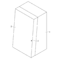
図1は、本実施形態のヒンジが使用される遊戯機の斜視図を示す。図1は、扉2が閉じた状態を示し、図2は、閉じ位置から扉2が85度開いた状態を示す。遊戯機は、本体1と、扉2と、を備える。扉2の前面には、シリンダ錠3が設けられる。シリンダ錠3に鍵をさし、鍵を回転させると扉2を開くことができる。図2に示すように、本体1は、前面が開口した箱形である。扉2は後面が開口した深さの浅い箱形である。例えばストッロマシンの場合、本体1には、複数のリール、回路基板等が収容される。扉2には、複数のリールを表示させる表示窓、スタートレバー、リールを停止するためのストップボタン、ゲームを演出する液晶表示体等が収容される。なお、以下においては、説明の便宜上、特に明示がない限り、遊戯機を前方から見たときの方向を用いて、各部の構成を説明する。   FIG. 1 shows a perspective view of a game machine in which the hinge of this embodiment is used. FIG. 1 shows a state in which the door 2 is closed, and FIG. 2 shows a state in which the door 2 is opened 85 degrees from the closed position. The game machine includes a main body 1 and a door 2. A cylinder lock 3 is provided on the front surface of the door 2. The door 2 can be opened by putting a key on the cylinder lock 3 and rotating the key. As shown in FIG. 2, the main body 1 has a box shape with an open front surface. The door 2 has a shallow box shape with an open rear surface. For example, in the case of a slot machine, the main body 1 accommodates a plurality of reels, circuit boards and the like. The door 2 accommodates a display window for displaying a plurality of reels, a start lever, a stop button for stopping the reels, a liquid crystal display for producing a game, and the like. In the following, for convenience of explanation, unless otherwise specified, the configuration of each part will be described using directions when the game machine is viewed from the front.

図2に示すように、本体1の前面側の一側部(図2における左側部)には、上下一対のヒンジ4を介して扉2が水平方向に回転可能に支持される。扉2が自重によって閉じるように、本体1の前面は垂直面に対して所定角度(例えば10度)だけ傾斜している。ヒンジ4の枢軸も垂直面に対して所定角度だけ傾斜している。   As shown in FIG. 2, the door 2 is supported on one side of the front side of the main body 1 (left side in FIG. 2) via a pair of upper and lower hinges 4 so as to be rotatable in the horizontal direction. The front surface of the main body 1 is inclined by a predetermined angle (for example, 10 degrees) with respect to the vertical surface so that the door 2 is closed by its own weight. The pivot axis of the hinge 4 is also inclined by a predetermined angle with respect to the vertical plane.

本体1の前面側の他側部(図2において右側部)と扉2の背面側の他側部には、施錠装置8が設けられる。施錠装置8は、本体1に設けられる本体側ユニット6と、扉2に設けられる扉側ユニット7と、を備える。本体側ユニット6には、一対の鉤部材9a,9bを有する可動板が上下方向に移動可能に組み込まれる。扉側ユニット7には、一対の鉤部材9a,9bに係合可能な一対のロック部材10a,10bが設けられる。扉2を閉めると、扉側ユニット7のローラ11が可動板を上方向に移動させる。扉2の閉じ位置では、ローラ11が可動板を通過し、可動板がその自重によって下方に移動する。これにより、可動板の一対の鉤部材9a,9bが一対のロック部材10a,10bに係合し、扉2が閉じ位置に保持される。閉じ位置にある扉2を開くときは、鍵で扉2のシリンダ錠3を回し、解錠操作板12を介して可動板を上方向に移動させる。これにより、一対の鉤部材9a,9bと一対のロック部材10a,10bの係合が解除されて、扉2を開くことが可能になる。なお、施錠装置8の詳細な構成は、出願人が提案した特許第5297781号に記載されている。   Locking devices 8 are provided on the other side of the main body 1 on the front side (the right side in FIG. 2) and the other side of the back side of the door 2. The locking device 8 includes a main body side unit 6 provided on the main body 1 and a door side unit 7 provided on the door 2. A movable plate having a pair of flange members 9a and 9b is incorporated in the main unit 6 so as to be movable in the vertical direction. The door-side unit 7 is provided with a pair of lock members 10a and 10b that can be engaged with the pair of flange members 9a and 9b. When the door 2 is closed, the roller 11 of the door side unit 7 moves the movable plate upward. At the closed position of the door 2, the roller 11 passes through the movable plate, and the movable plate moves downward by its own weight. Thereby, a pair of collar members 9a and 9b of a movable plate engage with a pair of lock members 10a and 10b, and door 2 is held in a closed position. When opening the door 2 in the closed position, the cylinder lock 3 of the door 2 is turned with a key, and the movable plate is moved upward via the unlocking operation plate 12. Thereby, the engagement between the pair of flange members 9a and 9b and the pair of lock members 10a and 10b is released, and the door 2 can be opened. The detailed configuration of the locking device 8 is described in Japanese Patent No. 52977781 proposed by the applicant.

図3は、遊戯機の水平断面図(ヒンジの側面図)を示す。図3(a)は扉2が閉じ位置にあるときを示し、図3(b)は閉じ位置から扉2が85度開いた状態を示し、図3(c)は扉2が開き位置にあるときを示す。図3(c)に示すように、ヒンジ4は、本体1に取り付けられる本体側部材21と、扉2に取り付けられる扉側部材22と、本体側部材21と扉側部材22とを連結する関節継手としての第一及び第二リンク23,24(2本のリンク)とを備える。第一リンク23は、一端部が本体側部材21に枢軸13を介して回転可能に連結され、他端部が扉側部材22に枢軸14を介して回転可能に連結される。第二リンク24は、一端部が本体側部材21に枢軸15を介して回転可能に連結され、他端部が扉側部材22に枢軸16を介して回転可能に連結される。本体側部材21、扉側部材22、第一リンク23、第二リンク24で四節回転連鎖が構成される。このヒンジ4は、スライドヒンジとも呼ばれ、扉2と本体1との干渉を避けるように扉2を前方に持ち出しながら回転させることができる。   FIG. 3 shows a horizontal sectional view (side view of the hinge) of the game machine. 3A shows a state in which the door 2 is in the closed position, FIG. 3B shows a state in which the door 2 is opened 85 degrees from the closed position, and FIG. 3C shows the door 2 in the open position. Show the time. As shown in FIG. 3C, the hinge 4 includes a main body side member 21 attached to the main body 1, a door side member 22 attached to the door 2, and a joint that connects the main body side member 21 and the door side member 22. First and second links 23 and 24 (two links) as a joint are provided. One end of the first link 23 is rotatably connected to the main body side member 21 via the pivot 13, and the other end is rotatably connected to the door side member 22 via the pivot 14. One end of the second link 24 is rotatably connected to the main body side member 21 via the pivot 15, and the other end is rotatably connected to the door side member 22 via the pivot 16. The main body side member 21, the door side member 22, the first link 23, and the second link 24 constitute a four-bar rotation chain. The hinge 4 is also called a slide hinge, and can be rotated while taking the door 2 forward so as to avoid interference between the door 2 and the main body 1.

本体側部材21には、第一アーム31の一端部が枢軸13を介して回転可能に支持される。第一アーム31の枢軸13と第一リンク23の枢軸13とは兼用される。扉側部材22には、第二アーム32の一端部が枢軸17を介して回転可能に支持される。第一アーム31の他端部と第二アーム32の他端部とは、枢軸18を介して互いに回転可能に連結される。第一アーム31の他端部及び第二アーム32の他端部には、摩擦力を発生させて第一アーム31に対する第二アーム32の相対的な回転に抵抗する摩擦力発生部33(図4参照)が設けられる。   One end of the first arm 31 is rotatably supported by the main body side member 21 via the pivot 13. The pivot 13 of the first arm 31 and the pivot 13 of the first link 23 are combined. One end of the second arm 32 is rotatably supported by the door side member 22 via the pivot 17. The other end of the first arm 31 and the other end of the second arm 32 are coupled to each other via the pivot 18 so as to be rotatable. A frictional force generator 33 (see FIG. 2) generates a frictional force at the other end of the first arm 31 and the other end of the second arm 32 to resist relative rotation of the second arm 32 with respect to the first arm 31. 4) is provided.

図4は、ヒンジ4の斜視図を示す。図4(a)は扉側部材22が85度開いた状態を示し、図4(b)は扉側部材22が10度開いた状態を示し、図4(c)は扉側部材22が閉じ位置にあるときを示す。上記のように、本体側部材21には、第一アーム31が枢軸13を介して回転可能に支持される。扉側部材22には、第二アーム32が枢軸17を介して回転可能に支持される。第一アーム31と第二アーム32とは枢軸18を介して連結されており、第一アーム31と第二アーム32との連結部には、摩擦力発生部33が配置される。図4(c)に示すように、扉2の閉じ位置において、摩擦力発生部33は本体側部材21のウェブ42b(本体1から最も離れた端面)を超えて本体1側(図4(c)の下側)に位置する。   FIG. 4 shows a perspective view of the hinge 4. 4A shows a state where the door-side member 22 is opened 85 degrees, FIG. 4B shows a state where the door-side member 22 is opened 10 degrees, and FIG. 4C shows a state where the door-side member 22 is closed. Indicates when in position. As described above, the first arm 31 is rotatably supported by the main body side member 21 via the pivot 13. A second arm 32 is rotatably supported by the door side member 22 via the pivot 17. The first arm 31 and the second arm 32 are connected via the pivot 18, and a frictional force generating portion 33 is disposed at the connecting portion between the first arm 31 and the second arm 32. As shown in FIG. 4 (c), in the closed position of the door 2, the frictional force generating part 33 exceeds the web 42b (the end surface farthest from the main body 1) of the main body side member 21 and the main body 1 side (FIG. 4 (c). ) Located on the lower side).

図5のヒンジの平面図に示すように、摩擦力発生部33が本体側部材21に干渉しないように、摩擦力発生部33は本体側部材21の片側(図5の下側)にのみ配置される。ただし、摩擦力発生部33が本体側部材21に干渉しなければよく、第一及び第二アーム31,32、摩擦力発生部33を本体側部材21の両側に配置することもできる。   As shown in the plan view of the hinge in FIG. 5, the frictional force generating part 33 is arranged only on one side (lower side in FIG. 5) so that the frictional force generating part 33 does not interfere with the main body side member 21. Is done. However, it is sufficient that the frictional force generating portion 33 does not interfere with the main body side member 21, and the first and second arms 31 and 32 and the frictional force generating portion 33 can be arranged on both sides of the main body side member 21.

図6及び図7のヒンジ4の分解斜視図を参照して、ヒンジ4の詳細な構成を説明する。図6は、第一及び第二アーム31,32、摩擦力発生部33のみを分解した斜視図を示し、図7は、ヒンジ4の全体を分解した斜視図を示す。   A detailed configuration of the hinge 4 will be described with reference to an exploded perspective view of the hinge 4 in FIGS. 6 and 7. 6 shows a perspective view in which only the first and second arms 31 and 32 and the frictional force generator 33 are disassembled, and FIG. 7 shows a perspective view in which the entire hinge 4 is disassembled.

図6に示すように、本体側部材21は、本体1に取付けられるマウンティングプレート41と、マウンティングプレート41に着脱可能に取り付けられるヒンジ本体42と、を備える。第一アーム31は、一端部がヒンジ本体42の側板42aに枢軸13を介して回転可能に支持される。枢軸13は、ヒンジ本体42の一対の側板42aに掛け渡される。第一アーム31の一端部の孔31aには、枢軸13が貫通する軸受43が嵌められる。第一アーム31は軸受43と一緒に枢軸13の回りを回転する。第一アーム31は、一端部から他端部に至る途中が折り曲げられていて、一端部と他端部との間に段差31bが形成される。段差31bによって第一アーム31の他端部がヒンジ本体42の側板42aから離れる。摩擦力発生部33とヒンジ本体42との干渉を避けるためである。第一アーム31の他端部の孔31cには、枢軸18が嵌められる。第二アーム32は、一端部が扉側部材22のブラケット22dに枢軸17を介して回転可能に支持される。第二アーム32の一端部の孔32aには、枢軸17が貫通する軸受44が嵌められる。第二アーム32は、軸受44と一緒に枢軸17の回りを回転する。第二アーム32の他端部の孔32bには、枢軸18が貫通する。   As shown in FIG. 6, the main body side member 21 includes a mounting plate 41 that is attached to the main body 1 and a hinge main body 42 that is detachably attached to the mounting plate 41. One end of the first arm 31 is rotatably supported by the side plate 42 a of the hinge body 42 via the pivot 13. The pivot 13 is stretched over a pair of side plates 42 a of the hinge body 42. A bearing 43 through which the pivot 13 passes is fitted into the hole 31 a at one end of the first arm 31. The first arm 31 rotates around the pivot 13 together with the bearing 43. The first arm 31 is bent halfway from one end to the other end, and a step 31b is formed between the one end and the other end. The other end of the first arm 31 is separated from the side plate 42a of the hinge body 42 by the step 31b. This is to avoid interference between the frictional force generating portion 33 and the hinge body 42. The pivot 18 is fitted in the hole 31 c at the other end of the first arm 31. One end of the second arm 32 is rotatably supported by the bracket 22 d of the door side member 22 via the pivot 17. A bearing 44 through which the pivot 17 passes is fitted into the hole 32 a at one end of the second arm 32. The second arm 32 rotates about the pivot 17 together with the bearing 44. The pivot 18 passes through the hole 32 b at the other end of the second arm 32.

摩擦力発生部33は、第一アーム31と第二アーム32との間に介在する摩擦板45と、第一アーム31と第二アーム32との間に摩擦板45を締め付ける締付け手段としての弾性体47と、を備える。第一アーム31と弾性体47との間にも、これらの直接的な接触を避けるために摩擦板46が介在する。枢軸18は、摩擦板45,46及び弾性体47を貫通する。弾性体47は、皿バネ、又は周方向に波が形成された円環形の板バネからなる。弾性体47は、枢軸18のフランジと摩擦板46との間に介在し、第二アーム32、摩擦板45、第一アーム31、摩擦板46を軸方向に締め付ける。摩擦力発生部33によって、第一アーム31と第二アーム32との間に摩擦力が発生する。   The frictional force generating portion 33 is an elastic member serving as a friction plate 45 interposed between the first arm 31 and the second arm 32 and an elastic member serving as a tightening means for tightening the friction plate 45 between the first arm 31 and the second arm 32. And a body 47. A friction plate 46 is also interposed between the first arm 31 and the elastic body 47 in order to avoid such direct contact. The pivot 18 passes through the friction plates 45 and 46 and the elastic body 47. The elastic body 47 is composed of a disc spring or an annular leaf spring in which a wave is formed in the circumferential direction. The elastic body 47 is interposed between the flange of the pivot 18 and the friction plate 46, and tightens the second arm 32, the friction plate 45, the first arm 31, and the friction plate 46 in the axial direction. A frictional force is generated between the first arm 31 and the second arm 32 by the frictional force generator 33.

なお、摩擦力発生部33の構成は上記の実施形態に限られない。例えば摩擦力発生部を、第一アームに固定された枢軸と、枢軸と一体のプラスチック製筒体と、プラスチック製筒体の外周を取り巻くヘアピン形の板バネと、板バネを第二アームに固定するボルトと、から構成することもできる。この場合、板バネでプラスチック製筒体を締め付けると、板バネとプラスチック製筒体との間に摩擦力が発生する。また、摩擦力発生部材を、第一アームに固定された枢軸と、枢軸に回転不能に嵌まれる筒体と、から構成することもできる。筒体を第二アームの孔に回転可能に圧入すれば、筒体と第二アームとの間に摩擦力が発生する。   In addition, the structure of the frictional force generation part 33 is not restricted to said embodiment. For example, the frictional force generation part is fixed to the first arm, the plastic cylinder integrated with the pivot, the hairpin-shaped plate spring surrounding the plastic cylinder, and the plate spring is fixed to the second arm. It can also be comprised from the bolt which carries out. In this case, when the plastic cylinder is tightened with the leaf spring, a frictional force is generated between the leaf spring and the plastic cylinder. Further, the frictional force generating member can be constituted by a pivot fixed to the first arm and a cylindrical body fitted non-rotatably on the pivot. If the cylinder is press-fitted rotatably into the hole of the second arm, a frictional force is generated between the cylinder and the second arm.

図7に示すように、ヒンジ本体42は、マウンティングプレート41にワンタッチで着脱される。マウンティングプレート41は、プレート本体49と、プレート本体49に支持軸49dを介して回転可能に支持されるロックレバー48と、を備える。プレート本体49は、一対の側板49aと、側板49aの上端部(図7の上端部)間に架け渡されたウェブ49bと、一対の側板49aの下端部から離間するように曲げられた一対の取付け板49cと、を備える。取付け板49cには、プレート本体49を本体1に取り付けるためのねじの通る孔が開けられる。側板49aの長さ方向の一端部には、支持軸41aが架け渡される。   As shown in FIG. 7, the hinge body 42 is attached to and detached from the mounting plate 41 with one touch. The mounting plate 41 includes a plate main body 49 and a lock lever 48 that is rotatably supported by the plate main body 49 via a support shaft 49d. The plate body 49 includes a pair of side plates 49a, a web 49b spanned between the upper ends of the side plates 49a (upper end portions in FIG. 7), and a pair of bent side walls 49a. A mounting plate 49c. A hole through which a screw for attaching the plate main body 49 to the main body 1 passes is formed in the attachment plate 49c. A support shaft 41a is stretched over one end of the side plate 49a in the length direction.

側板49aの長さ方向の他端部には、支持軸49dを介してロックレバー48が回転可能に支持される。ロックレバー48は、図示しないトーションバネによって、図7中時計方向に回転付勢される。ロックレバー48の係止突起48aがプレート本体49の側板49aに突き当たることによって、ロックレバー48のそれ以上の回転が制限される。ロックレバー48には、カム面48bが形成される。カム面48bの形状は後述する。   A lock lever 48 is rotatably supported on the other end portion in the length direction of the side plate 49a via a support shaft 49d. The lock lever 48 is urged to rotate clockwise in FIG. 7 by a torsion spring (not shown). When the locking protrusion 48a of the lock lever 48 abuts against the side plate 49a of the plate body 49, further rotation of the lock lever 48 is restricted. A cam surface 48 b is formed on the lock lever 48. The shape of the cam surface 48b will be described later.

ヒンジ本体42は、一対の側板42aと、側板42aの上端部間に架け渡されたウェブ42bと、を有して、断面U字形に形成される。側板42aの下端には、開放溝42cが形成される。開放溝42cにプレート本体49の支持軸41aを挿入することで、ヒンジ本体42がプレート本体49に回転可能に引っ掛かる。ヒンジ本体42の側板42aには、第一リンク23及び第一アーム31を回転可能に支持する枢軸13が架け渡される。側板42aの長さ方向の一端部には、第二リンク24を回転可能に支持する枢軸15が架け渡される。側板42aの長さ方向の他端部には、係合軸51が架け渡される。   The hinge body 42 has a pair of side plates 42a and a web 42b spanned between the upper ends of the side plates 42a, and is formed in a U-shaped cross section. An open groove 42c is formed at the lower end of the side plate 42a. By inserting the support shaft 41a of the plate main body 49 into the open groove 42c, the hinge main body 42 is rotatably caught on the plate main body 49. A pivot 13 that rotatably supports the first link 23 and the first arm 31 is bridged on the side plate 42 a of the hinge body 42. A pivot 15 that rotatably supports the second link 24 is spanned on one end of the side plate 42a in the length direction. An engagement shaft 51 is bridged over the other end portion in the length direction of the side plate 42a.

ヒンジ本体42をマウンティングプレート41に引っ掛け、マウンティングプレート41に向かって押し込むと、ヒンジ本体42の係合軸51がロックレバー48のカム面48bに当接する。この状態でさらに、ヒンジ本体42を押し込むと、ロックレバー48が反時計方向に回転し、係合軸51がカム面48bを乗り越える。すると、今度はロックレバー48が時計方向に回転し、係合軸51を掴む。これにより、ヒンジ本体42がマウンティングプレート41に取り付けられる。ヒンジ本体42を取り外すときは、ロックレバー48を反時計方向に回転させればよい。ヒンジ本体42には、ロックレバー48に係合してロックレバー48の誤動作を防止する線状バネ53が取り付けられる。   When the hinge main body 42 is hooked on the mounting plate 41 and pushed toward the mounting plate 41, the engaging shaft 51 of the hinge main body 42 abuts on the cam surface 48 b of the lock lever 48. When the hinge main body 42 is further pushed in this state, the lock lever 48 rotates counterclockwise, and the engagement shaft 51 gets over the cam surface 48b. Then, this time, the lock lever 48 rotates clockwise and grips the engagement shaft 51. Thereby, the hinge main body 42 is attached to the mounting plate 41. When removing the hinge main body 42, the lock lever 48 may be rotated counterclockwise. A linear spring 53 that is engaged with the lock lever 48 and prevents the lock lever 48 from malfunctioning is attached to the hinge body 42.

なお、上記実施形態では、ヒンジ本体42とマウンティングプレート41とを着脱自在にする例を説明したが、ヒンジ本体42をマウンティングプレート41に一体にすることもできるし、ヒンジ本体42の位置が調整可能なように、ヒンジ本体42とマウンティングプレート41との間に位置調整部材を介在させることもできる。   In the above embodiment, an example in which the hinge main body 42 and the mounting plate 41 are detachable has been described. However, the hinge main body 42 can be integrated with the mounting plate 41, and the position of the hinge main body 42 can be adjusted. As described above, a position adjusting member may be interposed between the hinge body 42 and the mounting plate 41.

扉側部材22は、一対の側板22aと、側板22aの下端部間に架け渡されたウェブ22bと、一対の側板22aの上端部から離間するように曲げられた一対の取付け板22cと、を備える。取付け板22cには、扉側部材22を扉2に取り付けるためのねじの通し孔が開けられる。一方の取付け板22cには、ブラケット22dが折り曲げて形成される。ブラケット22dには、第二アーム32が枢軸17を介して回転可能に支持される。側板22aには、第一リンク23を回転可能に支持する枢軸14、第二リンク24を回転可能に支持する枢軸16が架け渡される。側板22aの内側には、第二リンク24の側面に接して第二リンク24が回転するのを案内する樹脂製の案内板52が配置される。ウェブ22bには、第二リンク24との干渉を避けるための四角形の切欠き22b1が形成される。   The door-side member 22 includes a pair of side plates 22a, a web 22b spanned between the lower ends of the side plates 22a, and a pair of mounting plates 22c bent so as to be separated from the upper ends of the pair of side plates 22a. Prepare. A screw through-hole for attaching the door side member 22 to the door 2 is opened in the attachment plate 22c. A bracket 22d is formed by bending one mounting plate 22c. The second arm 32 is rotatably supported by the bracket 22d via the pivot 17. A pivot 14 that rotatably supports the first link 23 and a pivot 16 that rotatably supports the second link 24 are bridged over the side plate 22a. Inside the side plate 22a, a resin-made guide plate 52 is disposed to contact the side surface of the second link 24 and guide the rotation of the second link 24. The web 22b is formed with a rectangular notch 22b1 for avoiding interference with the second link 24.

第一リンク23は、一対の側板23aと、側板23aの上端部に架け渡されたウェブ23bと、を有して、断面U字形に形成される。第一リンク23の一端部は、ヒンジ本体42の一対の側板42aの内側に配置される。第一リンク23の一端部は、枢軸13を介してヒンジ本体42に回転可能に支持される。第一リンク23の他端部は、第二リンク24の一対の側板24aの内側に配置される。第一リンク23の他端部は、枢軸14を介して扉側部材22に回転可能に支持される。   The first link 23 has a pair of side plates 23a and a web 23b spanning the upper end portion of the side plates 23a, and is formed in a U-shaped cross section. One end of the first link 23 is disposed inside the pair of side plates 42 a of the hinge body 42. One end of the first link 23 is rotatably supported by the hinge body 42 via the pivot 13. The other end of the first link 23 is disposed inside the pair of side plates 24 a of the second link 24. The other end of the first link 23 is rotatably supported by the door side member 22 via the pivot 14.

第二リンク24は、一対の側板24aと、側板24aの上端部に架け渡されたウェブ24bと、を有して、断面U字形に形成される。第二リンク24の一端部は、ヒンジ本体42の一対の側板42aの内側に配置される。第二リンク24の一端部は、枢軸15を介してヒンジ本体42に回転可能に支持される。第二リンク24の他端部は、扉側部材22の側板22aの内側に配置される。第二リンク24の他端部は、枢軸16を介して扉側部材22に回転可能に支持される。   The second link 24 has a pair of side plates 24a and a web 24b spanning the upper end of the side plates 24a, and is formed in a U-shaped cross section. One end of the second link 24 is disposed inside the pair of side plates 42 a of the hinge body 42. One end of the second link 24 is rotatably supported by the hinge body 42 via the pivot 15. The other end of the second link 24 is disposed inside the side plate 22 a of the door side member 22. The other end of the second link 24 is rotatably supported by the door side member 22 via the pivot 16.

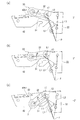
図8及び図9は、扉側部材22の開き角度に伴うヒンジの動作図を示す。図8、図9の右側の数字が扉側部材22の開き角度を示す。図8、図9には、扉側部材22の開き角度が85度、45度、10度、3度、1度、−2度の場合が示される。扉側部材22の開き角度は、扉2の開き角度に一致する。ただし、扉2を完全に閉めることができるように、扉側部材22の開き角度にはマージンが設けられる。すなわち、図9(c)に示すように、扉2が閉じ位置にあっても、扉側部材22はさらに2度だけ閉じ方向に回転できる。   8 and 9 show operation diagrams of the hinge according to the opening angle of the door-side member 22. The numbers on the right side of FIGS. 8 and 9 indicate the opening angle of the door side member 22. FIGS. 8 and 9 show cases where the opening angle of the door-side member 22 is 85 degrees, 45 degrees, 10 degrees, 3 degrees, 1 degree, and -2 degrees. The opening angle of the door-side member 22 matches the opening angle of the door 2. However, a margin is provided in the opening angle of the door-side member 22 so that the door 2 can be completely closed. That is, as shown in FIG. 9C, even when the door 2 is in the closed position, the door-side member 22 can further rotate in the closing direction by 2 degrees.

上記のように、ヒンジ本体42、扉側部材22、第一リンク23、第二リンク24が、四節回転連鎖を構成する。ヒンジ本体42が本体1に固定されているので、扉側部材22は四節回転連鎖の瞬間中心を中心にして回転する。図8(b)に示すように、瞬間中心Pは、第一リンク23の両端の枢軸13と枢軸14を結んだ破線L1と第二リンク24の両端の枢軸15と枢軸16を結んだ破線L2との交点である。図8(a)〜図8(c)、図9(a)〜図9(c)に示すように、瞬間中心Pの位置を変化させることで、扉2を前方に持ち出しながら開くことができる。   As described above, the hinge body 42, the door-side member 22, the first link 23, and the second link 24 constitute a four-node rotating chain. Since the hinge main body 42 is fixed to the main body 1, the door-side member 22 rotates around the instantaneous center of the four-node rotation chain. As shown in FIG. 8B, the instantaneous center P is defined by a broken line L1 connecting the pivots 13 and 14 at both ends of the first link 23, and a broken line L2 connecting the pivots 15 and 16 at both ends of the second link 24. Is the intersection of As shown in FIGS. 8A to 8C and FIGS. 9A to 9C, by changing the position of the instantaneous center P, the door 2 can be opened while being taken forward. .

図8(a)→図8(b)→図8(c)に示すように、扉側部材22の開き角度が85度から10度まで小さくなるにつれて、第一アーム31と第二アーム32とのなす角度θも小さくなる。第一アーム31と第二アーム32との間には、摩擦力発生部33によって摩擦力が発生している。このため、摩擦力によってヒンジ4にトルクが発生し、扉2を任意の開き角度で保持することができる。   As shown in FIG. 8 (a) → FIG. 8 (b) → FIG. 8 (c), as the opening angle of the door-side member 22 decreases from 85 degrees to 10 degrees, the first arm 31 and the second arm 32 The angle θ formed by is also reduced. A friction force is generated between the first arm 31 and the second arm 32 by the friction force generator 33. For this reason, torque is generated in the hinge 4 by the frictional force, and the door 2 can be held at an arbitrary opening angle.

図9(a)→図9(b)→図9(c)に示すように、扉側部材22の開き角度が3度以下(扉側部材22の閉じ位置近傍)のとき、摩擦力発生部33の少なくとも一部がヒンジ本体42に重なる。すなわち、摩擦力発生部33の少なくとも一部がヒンジ本体42の端面42b1(ウェブ42bの上面)よりも本体1側に入る。図9(c)に示すように、扉側部材22の閉じ位置では、摩擦力発生部33の全部がヒンジ本体42に重なる。   As shown in FIG. 9 (a) → FIG. 9 (b) → FIG. 9 (c), when the opening angle of the door-side member 22 is 3 degrees or less (near the closed position of the door-side member 22), the frictional force generating portion At least a portion of 33 overlaps the hinge body 42. That is, at least a part of the frictional force generating portion 33 enters the main body 1 side with respect to the end surface 42b1 of the hinge main body 42 (the upper surface of the web 42b). As shown in FIG. 9C, the frictional force generating portion 33 entirely overlaps the hinge body 42 at the closed position of the door side member 22.

そして、扉側部材22の閉じ位置では、第二アーム32の枢軸17と瞬間中心Pとを結んだ実線L3が、第一アーム31の枢軸13と瞬間中心Pとを結んだ破線L1を越える。すなわち、図9(a)に示すように、破線L1の一方側(右側)にあった実線L3が、図9(c)に示すように、破線L1を跨って破線L1の他方側(左側)に移動する。ここで、第一アーム31の枢軸13と第一リンク23の枢軸13とは兼用されているので、破線L1は瞬間中心を求めるときの破線L1(図8(b)参照)に一致する。   And in the closed position of the door side member 22, the solid line L3 which connected the pivot 17 and the instantaneous center P of the 2nd arm 32 exceeds the broken line L1 which connected the pivot 13 and the instantaneous center P of the 1st arm 31. That is, as shown in FIG. 9A, the solid line L3 on one side (right side) of the broken line L1 crosses over the broken line L1, as shown in FIG. 9C, and the other side (left side) of the broken line L1. Move to. Here, since the pivot 13 of the first arm 31 and the pivot 13 of the first link 23 are combined, the broken line L1 coincides with the broken line L1 (see FIG. 8B) when the instantaneous center is obtained.

図9(c)に示すように、扉側部材22の閉じ位置において、実線L3が破線L1を超えるようにすることで、扉側部材22の閉じ位置近傍において、枢軸13と枢軸17との距離を略一定に保つことができ、第一アーム31と第二アーム32のなす角度θを略一定にすることができる。したがって、扉側部材22の閉じ位置近傍では、ヒンジ4にはトルクが略発生せず、扉2を容易に閉じることができる。ここで、厳密にいえば、扉側部材22の閉じ位置近傍において角度θが僅かに変化しているが、このような場合も含めて「略一定」という。   As shown in FIG. 9C, the distance between the pivot 13 and the pivot 17 in the vicinity of the closed position of the door side member 22 by making the solid line L3 exceed the broken line L1 at the closed position of the door side member 22. Can be kept substantially constant, and the angle θ between the first arm 31 and the second arm 32 can be made substantially constant. Therefore, in the vicinity of the closing position of the door-side member 22, torque is not substantially generated in the hinge 4, and the door 2 can be easily closed. Strictly speaking, the angle θ slightly changes in the vicinity of the closed position of the door-side member 22, but it is referred to as “substantially constant” including such a case.

図9に示すように、扉側部材22の閉じ位置近傍では、第一アーム31と第二アーム32とのなす角度θは略一定であるものの、第一アーム31と第二アーム32とは大きく反時計方向に回転する。摩擦力発生部33がヒンジ本体42の端面42b1よりも本体1側に入るようにすることで、第一アーム31及び第二アーム32の反時計方向の大きな回転を許容することができる。   As shown in FIG. 9, in the vicinity of the closed position of the door-side member 22, the angle θ formed by the first arm 31 and the second arm 32 is substantially constant, but the first arm 31 and the second arm 32 are large. Rotates counterclockwise. By allowing the frictional force generating portion 33 to enter the main body 1 side with respect to the end surface 42b1 of the hinge main body 42, large rotation in the counterclockwise direction of the first arm 31 and the second arm 32 can be permitted.

図10は、本実施形態のヒンジを上蓋付きキャビネットに使用した例を示す。キャビネット61の上面には、開口が開けられる。上蓋62は、ヒンジ4を介して水平軸の回りを回転可能にキャビネット61に取り付けられる。ヒンジ4の構成は、図2に示すヒンジ4と同一である。この例でも、上蓋62を任意の開き角度で保持することができ、また上蓋62を容易に閉じることができる。なお、キャビネットの下面の開口を下蓋で開閉する下蓋付きキャビネットに本実施形態のヒンジを使用することもできる。   FIG. 10 shows an example in which the hinge of this embodiment is used in a cabinet with an upper lid. An opening is opened on the upper surface of the cabinet 61. The upper lid 62 is attached to the cabinet 61 via the hinge 4 so as to be rotatable about a horizontal axis. The configuration of the hinge 4 is the same as that of the hinge 4 shown in FIG. Also in this example, the upper lid 62 can be held at an arbitrary opening angle, and the upper lid 62 can be easily closed. In addition, the hinge of this embodiment can also be used for the cabinet with a lower cover which opens and closes opening of the lower surface of a cabinet with a lower cover.

図11は、本実施形態のヒンジ4を吊戸棚等の上開き扉付きのキャビネットに適用した例を示す。キャビネット71の前面には、開口が開けられる。扉72は、ヒンジ4を介してキャビネット71の天板に水平軸の回りを回転可能に取り付けられる。この例でも、扉72の任意の開き角度を保持することができ、また扉72を容易に閉じることができる。なお、キャビネットの底板にヒンジを介して下開き扉を取り付けることもできる。   FIG. 11 shows an example in which the hinge 4 of the present embodiment is applied to a cabinet with an upper door such as a hanging cabinet. An opening is opened in the front surface of the cabinet 71. The door 72 is attached to the top plate of the cabinet 71 via the hinge 4 so as to be rotatable around a horizontal axis. Also in this example, an arbitrary opening angle of the door 72 can be maintained, and the door 72 can be easily closed. A lower opening door can be attached to the bottom plate of the cabinet via a hinge.

本発明は上記実施形態に具現化されるのに限られることはなく、本発明の要旨を変更しない範囲でさまざまな実施形態に変更可能である。   The present invention is not limited to the embodiment described above, and can be changed to various embodiments without departing from the gist of the present invention.

例えば、上記実施形態では、ヒンジを遊戯機、キャビネットに使用する例を説明したが、キャビネット以外の家具、建築物、半導体製造装置・検査機器等の機械の扉に使用することもできる。   For example, in the above-described embodiment, an example in which the hinge is used for a game machine or a cabinet has been described. However, the hinge may be used for a door of a machine other than the cabinet, such as furniture, a building, a semiconductor manufacturing apparatus and an inspection device.

上記実施形態では、本体側部材と扉側部材を連結する関節継手として2本のリンクを使用する例を説明したが、回転軸を介して2本のリンクをX字状に交差させることや、3本以上のリンクを使用することもできる。また、関節継手を軸から構成し、所謂1軸ヒンジにすることもできる。   In the said embodiment, although the example which uses two links as an articulated joint which connects a main body side member and a door side member was explained, crossing two links in X shape via a rotating shaft, It is possible to use more than two links. Further, the joint joint can be constituted by a shaft and can be a so-called uniaxial hinge.

上記実施形態では、扉の閉じ位置において、摩擦力発生部が本体側部材に重なるようにしているが、摩擦力発生部が扉側部材に重なるようにすることもできる。本実施形態のヒンジの本体側部材を扉に取り付け、扉側部材を本体に取り付けることもできるからである。   In the above embodiment, the frictional force generating part overlaps the main body side member at the door closing position, but the frictional force generating part may overlap the door side member. This is because the main body side member of the hinge of the present embodiment can be attached to the door and the door side member can be attached to the main body.

本実施形態のヒンジの各部の構成は一例であり、本発明の要旨を変更しない範囲で様々な構成に変更することができる。   The configuration of each part of the hinge of the present embodiment is an example, and can be changed to various configurations without changing the gist of the present invention.

1…本体
2…扉
4…ヒンジ
13…本体側部材に対する第一リンク(第一アーム)の枢軸
14…扉側部材に対する第一リンクの枢軸
15…本体側部材に対する第二リンクの枢軸
16…扉側部材に対する第二リンクの枢軸
17…扉側部材に対する第二アームの枢軸
18…第一アームに対する第二アームの枢軸
21…本体側部材
22…扉側部材
23…第一リンク(関節継手)
24…第二リンク(関節継手)
31…第一アーム
32…第二アーム
33…摩擦力発生部
42b1…本体側部材の端面
45…摩擦板
46…摩擦板
47…弾性体
61…キャビネット(本体)
62…上蓋(扉)
71…キャビネット(本体)
72…扉
L1…破線(本体側部材に対する第一アームの枢軸13と扉側部材の瞬間中心Pとを結んだ線)
L2…破線(瞬間中心を求めるための線)
L3…実線(扉側部材に対する第二アームの枢軸17と扉側部材の瞬間中心Pとを結んだ線)
P…瞬間中心
θ…第一アームと第二アームとのなす角度
DESCRIPTION OF SYMBOLS 1 ... Main body 2 ... Door 4 ... Hinge 13 ... The pivot 14 of the 1st link (1st arm) with respect to a body side member ... The pivot 15 of the 1st link with respect to a door side member ... The pivot 16 of the 2nd link with respect to a body side member ... Door The pivot 17 of the second link relative to the side member ... The pivot 18 of the second arm relative to the door side member ... The pivot 21 of the second arm relative to the first arm ... The body side member 22 ... The door side member 23 ... The first link (joint joint)
24 ... Second link (joint joint)
DESCRIPTION OF SYMBOLS 31 ... 1st arm 32 ... 2nd arm 33 ... Friction force generating part 42b1 ... End surface 45 of main body side member ... Friction plate 46 ... Friction plate 47 ... Elastic body 61 ... Cabinet (main body)
62 ... Upper lid (door)
71 ... Cabinet (main unit)
72 ... Door L1 ... Broken line (line connecting the pivot 13 of the first arm with respect to the body side member and the instantaneous center P of the door side member)
L2 ... dashed line (line for determining the instantaneous center)
L3: Solid line (line connecting the pivot 17 of the second arm with respect to the door side member and the instantaneous center P of the door side member)
P: Instantaneous center θ: Angle between the first arm and the second arm

Claims (7)

本体に取り付けられる本体側部材と、
扉に取り付けられ、前記本体側部材に関節継手を介して連結される扉側部材と、
一端部が前記本体側部材に回転可能に支持される第一アームと、
一端部が前記扉側部材に回転可能に支持され、他端部が前記第一アームに回転可能に連結される第二アームと、
前記第一アームの他端部と前記第二アームの前記他端部に設けられ、摩擦力を発生させて前記第一アームに対する前記第二アームの相対的な回転に抵抗する摩擦力発生部と、を備え
前記扉側部材の閉じ位置近傍において、前記第一アームと前記第二アームのなす角度を略一定にするヒンジ。
A body side member attached to the body;
A door side member attached to the door and connected to the main body side member via an articulated joint;
A first arm whose one end is rotatably supported by the body-side member;
A second arm whose one end is rotatably supported by the door side member and whose other end is rotatably connected to the first arm;
A friction force generator provided at the other end of the first arm and the other end of the second arm and generating a friction force to resist relative rotation of the second arm with respect to the first arm; , equipped with a,
A hinge that makes the angle formed by the first arm and the second arm substantially constant in the vicinity of the closed position of the door-side member .
前記扉側部材の閉じ位置において、前記第一アームに対する前記第二アームの枢軸の軸方向から見て、前記摩擦力発生部の少なくとも一部が前記本体側部材に重なり、又は前記摩擦力発生部の少なくとも一部が前記扉側部材に重なることを特徴とする請求項1に記載のヒンジ。   In the closed position of the door side member, at least a part of the frictional force generating part overlaps the main body side member when viewed from the axial direction of the pivot of the second arm with respect to the first arm, or the frictional force generating part The hinge according to claim 1, wherein at least a part of the hinge overlaps the door-side member. 前記扉側部材の閉じ位置において、前記第一アームに対する前記第二アームの枢軸の軸方向から見て、前記扉側部材に対する前記第二アームの枢軸と前記扉側部材の瞬間中心とを結んだ線が、前記本体側部材に対する前記第一アームの枢軸と前記瞬間中心とを結んだ線を越えることを特徴とする請求項1又は2に記載のヒンジ。   When viewed from the axial direction of the pivot of the second arm relative to the first arm, the pivot of the second arm relative to the door member and the instantaneous center of the door member are connected at the closed position of the door member. The hinge according to claim 1 or 2, wherein the line exceeds a line connecting the pivot axis of the first arm with respect to the main body side member and the instantaneous center. 前記摩擦力発生部が前記本体側部材に干渉しないように、前記摩擦力発生部が前記本体側部材の片側に配置されることを特徴とする請求項2又は3に記載のヒンジ。   The hinge according to claim 2 or 3, wherein the frictional force generating part is arranged on one side of the main body side member so that the frictional force generating part does not interfere with the main body side member. 前記摩擦力発生部は、前記第一アームと前記第二アームとの間に介在する摩擦板と、前記第一アームと前記第二アームとの間に前記摩擦板を締め付ける締付け手段と、を備えることを特徴とする請求項1ないし4のいずれか1項に記載のヒンジ。   The frictional force generating section includes a friction plate interposed between the first arm and the second arm, and a tightening means for tightening the friction plate between the first arm and the second arm. The hinge according to any one of claims 1 to 4, characterized in that: 前記関節継手は、2つのリンクから構成されることを特徴とする請求項1ないし5のいずれか1項に記載のヒンジ。   The hinge according to any one of claims 1 to 5, wherein the joint joint includes two links. 前記ヒンジは、枢軸が垂直面に対して所定角度だけ傾斜する遊戯機に用いられることを特徴とする請求項1ないし6のいずれか1項に記載のヒンジ。


The hinge according to any one of claims 1 to 6, wherein the hinge is used in a game machine in which a pivot is inclined at a predetermined angle with respect to a vertical plane.


JP2015155030A 2015-08-05 2015-08-05 Hinge Active JP6219345B2 (en)

Priority Applications (1)

Application Number Priority Date Filing Date Title
JP2015155030A JP6219345B2 (en) 2015-08-05 2015-08-05 Hinge

Applications Claiming Priority (1)

Application Number Priority Date Filing Date Title
JP2015155030A JP6219345B2 (en) 2015-08-05 2015-08-05 Hinge

Publications (2)

Publication Number Publication Date
JP2017031746A JP2017031746A (en) 2017-02-09
JP6219345B2 true JP6219345B2 (en) 2017-10-25

Family

ID=57989256

Family Applications (1)

Application Number Title Priority Date Filing Date
JP2015155030A Active JP6219345B2 (en) 2015-08-05 2015-08-05 Hinge

Country Status (1)

Country Link
JP (1) JP6219345B2 (en)

Families Citing this family (1)

* Cited by examiner, † Cited by third party
Publication number Priority date Publication date Assignee Title
US20220112761A1 (en) * 2020-10-09 2022-04-14 Paul Rodriguez Skateboard Storage Assembly

Family Cites Families (3)

* Cited by examiner, † Cited by third party
Publication number Priority date Publication date Assignee Title
JPH0750540Y2 (en) * 1989-04-18 1995-11-15 株式会社ニフコ Hinge device
JP3856601B2 (en) * 1999-07-22 2006-12-13 加藤電機株式会社 Tilt hinge
JP5451978B2 (en) * 2008-03-31 2014-03-26 日立オムロンターミナルソリューションズ株式会社 Panel opening / closing mechanism of automatic machine

Also Published As

Publication number Publication date
JP2017031746A (en) 2017-02-09

Similar Documents

Publication Publication Date Title
KR101441915B1 (en) Hinge device for electronic apparatus
JPH0450388Y2 (en)
JP3913759B2 (en) Door opening / closing mechanism
JP5313300B2 (en) Projecting rotary hinge device for housing
JP6230724B2 (en) Hinge and hinge bracket
JP6219345B2 (en) Hinge
KR101206621B1 (en) Hinge device of hidden-type
JP2013091925A (en) Hinge mounting unit
JP5279446B2 (en) Vehicle storage device
WO2020010866A1 (en) Lock structure of upper cover of case
JP2011226094A (en) Structure for preventing door from lowering on one side in cabinet
JP2009281000A (en) Lever handle device
JP2004124455A (en) Apparatus case
JP3023649B2 (en) Spring type door closer and door hinge device using the same
JP5372808B2 (en) Buried door hinge and door device
JP7292987B2 (en) Electrical equipment with a drum-type rotating tank
JP2013189774A (en) Operation mechanism of lid
JP5468500B2 (en) Door lock device
JP4732388B2 (en) Electronic equipment housing structure
JP5123529B2 (en) Retrofit auxiliary lock
JP2007315013A (en) Hinge structure of flip-up counter
JP2004316223A (en) Link mechanism and storage device using the same
JPH0142377Y2 (en)
JP2507444Y2 (en) Hinge device
JPH0324783Y2 (en)

Legal Events

Date Code Title Description
A131 Notification of reasons for refusal

Free format text: JAPANESE INTERMEDIATE CODE: A131

Effective date: 20170404

A521 Written amendment

Free format text: JAPANESE INTERMEDIATE CODE: A523

Effective date: 20170530

TRDD Decision of grant or rejection written
A01 Written decision to grant a patent or to grant a registration (utility model)

Free format text: JAPANESE INTERMEDIATE CODE: A01

Effective date: 20170926

A61 First payment of annual fees (during grant procedure)

Free format text: JAPANESE INTERMEDIATE CODE: A61

Effective date: 20170927

R150 Certificate of patent or registration of utility model

Ref document number: 6219345

Country of ref document: JP

Free format text: JAPANESE INTERMEDIATE CODE: R150