JP6217065B2 - Ophthalmic imaging equipment - Google Patents

Ophthalmic imaging equipment Download PDF

Info

Publication number
JP6217065B2
JP6217065B2 JP2012215479A JP2012215479A JP6217065B2 JP 6217065 B2 JP6217065 B2 JP 6217065B2 JP 2012215479 A JP2012215479 A JP 2012215479A JP 2012215479 A JP2012215479 A JP 2012215479A JP 6217065 B2 JP6217065 B2 JP 6217065B2
Authority
JP
Japan
Prior art keywords
scanning
fundus
image
light
unit
Prior art date
Legal status (The legal status is an assumption and is not a legal conclusion. Google has not performed a legal analysis and makes no representation as to the accuracy of the status listed.)
Active
Application number
JP2012215479A
Other languages
Japanese (ja)
Other versions
JP2014068703A (en
JP2014068703A5 (en
Inventor
尚久 柴田
尚久 柴田
昌明 羽根渕
昌明 羽根渕
Current Assignee (The listed assignees may be inaccurate. Google has not performed a legal analysis and makes no representation or warranty as to the accuracy of the list.)
Nidek Co Ltd
Original Assignee
Nidek Co Ltd
Priority date (The priority date is an assumption and is not a legal conclusion. Google has not performed a legal analysis and makes no representation as to the accuracy of the date listed.)
Filing date
Publication date
Application filed by Nidek Co Ltd filed Critical Nidek Co Ltd
Priority to JP2012215479A priority Critical patent/JP6217065B2/en
Publication of JP2014068703A publication Critical patent/JP2014068703A/en
Publication of JP2014068703A5 publication Critical patent/JP2014068703A5/ja
Application granted granted Critical
Publication of JP6217065B2 publication Critical patent/JP6217065B2/en
Active legal-status Critical Current
Anticipated expiration legal-status Critical

Links

Images

Description

本発明は眼底撮影をする眼科撮影装置に関する。 The present invention relates to an ophthalmic photographing apparatus which the fundus photographing.

波面補償部で眼の波面収差を取り除いた状態で眼底撮影画像を得る眼科撮影装置が提案されている。この種の眼科撮影装置は、眼底に投影される照明光を所要方向に偏向させる走査部材と、眼底からの反射光を受光する受光素子とを備え、受光素子で眼底からの反射光を繰り返し受光することで、眼底撮影画像の情報を取得している(例えば、特許文献1参照)。なお高解像度の眼底撮影画像を出来るだけ早く構成するためには、走査部材の往路と復路の両方で画像データが取得される事が好ましい。   There has been proposed an ophthalmologic photographing apparatus that obtains a fundus photographed image in a state where wavefront aberrations of the eye are removed by a wavefront compensation unit. This type of ophthalmic imaging apparatus includes a scanning member that deflects illumination light projected on the fundus in a required direction and a light receiving element that receives reflected light from the fundus, and the light receiving element repeatedly receives reflected light from the fundus. By doing so, the information of the fundus photographed image is acquired (see, for example, Patent Document 1). In order to construct a fundus photographic image with a high resolution as quickly as possible, it is preferable that image data be acquired in both the forward path and the backward path of the scanning member.

特開2010‐259543号公報JP 2010-259543 A 特開平11‐225965号公報Japanese Patent Laid-Open No. 11-225965

しかし走査部材の往復走査と、受光素子で画素が読み取られるタイミングとの間にばらつきが生じると、モニタに表示される眼底画像の画質が低下するおそれがある。   However, if a variation occurs between the reciprocating scanning of the scanning member and the timing at which the pixels are read by the light receiving element, the image quality of the fundus image displayed on the monitor may be degraded.

本発明は上記従来技術の問題点に鑑み、眼底の撮影画像を精度良く取得できる眼科撮影装置を提供することを技術課題とする。   In view of the above-described problems of the prior art, an object of the present invention is to provide an ophthalmologic photographing apparatus that can accurately obtain a photographed image of the fundus.

上記課題を解決するために、本発明は以下のような構成を備えることを特徴とする。
(1) 被検者眼の眼底を照明する照明光源を持つ照明光学系と、前記照明光源の光束を前記眼底に対して走査線毎に往復振動させる共振型光スキャナーを持ち、前記光束によって眼底上を二次元走査するための走査部材と、前記眼底からの反射光を受光して光電変換し所要の信号を出力する受光素子と、を備える眼底撮影光学系と、前記共振型光スキャナーによる往路走査と復路走査とが副走査方向に関して互いに異なる走査線で行われることにより眼底上が前記光束によって二次元走査されるように前記走査部材を制御する走査制御手段と、1フレーム分の二次元走査において前記受光素子から出力される信号に基づいて眼底画像を得る画像生成手段と、を備え、前記画像生成手段は、前記走査線毎の走査部材の往復振動で取得された前記信号に基づく前記撮影画像を、前記往路走査による画素列と、前記復路走査による画素列と、に区分けするための基準位置を定め、前記基準位置に基づいて区分けされた前記往路走査による素列を複数、副走査方向に並べることにより第1眼底画像データを生成すると共に、前記基準位置に基づいて区分けされた前記復路走査による素列を複数、副走査方向に並べることにより第2眼底画像データを生成し、前記往路走査による複数の画素列を含む前記第1眼底画像データと、前記復路走査による複数の画素列を含む前記第2眼底画像データとの相関に基づいて、前記基準位置を補正し、 補正後の基準位置に基づいて区分けされた往路走査による複数の画素列による第1眼底画像データと、補正後の基準位置に基づいて区分けされた復路走査による複数の画素列による第2眼底画像データと、を合成して、合成眼底画像を得る
In order to solve the above problems, the present invention is characterized by having the following configuration.
(1) An illumination optical system having an illumination light source that illuminates the fundus of the subject's eye and a resonance type optical scanner that reciprocally vibrates the light beam of the illumination light source with respect to the fundus for each scanning line. A fundus photographing optical system comprising a scanning member for two-dimensional scanning above, a light receiving element that receives reflected light from the fundus and photoelectrically converts it and outputs a required signal, and a forward path by the resonant optical scanner A scanning control means for controlling the scanning member so that the fundus is two-dimensionally scanned by the light beam by performing scanning and backward scanning with different scanning lines in the sub-scanning direction, and two-dimensional scanning for one frame Image generating means for obtaining a fundus image based on a signal output from the light receiving element in the image sensor, wherein the image generating means is acquired by reciprocal vibration of a scanning member for each scanning line. Said captured image based on the signal, and the pixel rows by the forward scanning, the determined pixel rows by the backward scan, the reference position for partitioning, the image by the forward scanning, which are divided on the basis of the reference position Motoretsu a plurality, generates a first fundus image data by arranging the sub-scanning direction, a plurality of image Motoretsu by divided by said backward scan on the basis of the reference position, the second fundus image by arranging the sub-scanning direction Data is generated, and the reference position is determined based on a correlation between the first fundus image data including a plurality of pixel rows by the forward scan and the second fundus image data including a plurality of pixel rows by the backward scan. corrected, the first fundus image data by a plurality of pixel columns by segmented the forward scanning on the basis of the reference position after the correction, the return path is divided on the basis of the reference position after the correction A second fundus image data by a plurality of pixel columns by査combines to give a composite fundus image.

本発明によれば、眼底の撮影画像を精度良く取得できる眼科撮影装置を提供できる。   According to the present invention, it is possible to provide an ophthalmologic photographing apparatus that can accurately obtain a fundus photographed image.

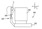
本発明の実施形態を説明する。図1は眼科撮影装置500の外観図である。眼科撮影装置500は、基台502、撮影部503、顔支持ユニット504を備える。基台502上に取り付けられた撮影部503の内部には後述する光学系が収納される。顔支持ユニット504は顎台505備え、顎台505は駆動手段(図示を略す)の駆動により顔支持ユニット4の基部に対して三次元方向に移動される。   An embodiment of the present invention will be described. FIG. 1 is an external view of an ophthalmologic photographing apparatus 500. The ophthalmologic photographing apparatus 500 includes a base 502, a photographing unit 503, and a face support unit 504. An optical system (to be described later) is housed inside the photographing unit 503 attached on the base 502. The face support unit 504 includes a chin rest 505, and the chin rest 505 is moved in a three-dimensional direction with respect to the base of the face support unit 4 by driving of a driving means (not shown).

図2に眼科撮影装置500の光学系の説明図を示す。光学系は第1撮影ユニット100と、第2撮影ユニット200を備える。第1撮影ユニット100は、被検眼Eを細胞レベルの解像度で撮影し眼底画像(以下、第1撮影画像と記す)を得る。第2撮影ユニット200は、第1撮影ユニット100よりも広い画角の眼底画像を取得し、第1撮影画像の撮影位置を指定する際に用いられる。   FIG. 2 illustrates an optical system of the ophthalmologic photographing apparatus 500. The optical system includes a first photographing unit 100 and a second photographing unit 200. The first imaging unit 100 captures the eye E with a cell-level resolution to obtain a fundus image (hereinafter referred to as a first captured image). The second photographing unit 200 is used when acquiring a fundus image having a wider angle of view than the first photographing unit 100 and designating the photographing position of the first photographed image.

第1撮影ユニット100は共焦点光学系を用いた走査型レーザー検眼鏡の構成とされ、眼Eに照明光(照明光束)を照射して眼底を2次元的に照明する第1照明光学系100aと、眼底に照射された照明光の反射光(反射光束)を受光して第1撮影画像を得る第1撮影光学系100b、更に眼Eの波面収差を検出して低次収差及び高次収差を取り除く波面補償ユニット110を有する。   The first photographing unit 100 is configured as a scanning laser ophthalmoscope using a confocal optical system. The first illumination optical system 100a illuminates the fundus two-dimensionally by irradiating the eye E with illumination light (illumination light beam). The first photographing optical system 100b that receives the reflected light (reflected light beam) of the illumination light applied to the fundus and obtains the first photographed image, and further detects the wavefront aberration of the eye E to detect low-order aberration and high-order aberration. Has a wavefront compensation unit 110 for removing.

(第1撮影ユニット)
第1照明光学系100aは光源1(第1光源)を備え、光源1から眼底に到る光路L1に、レンズ2、偏光ビームスプリッタ4、ビームスプリッタ71、凹面ミラー6、凹面ミラー7、平面ミラー8、波面補償デバイス72、ビームスプリッタ75、凹面ミラー11、凹面ミラー12、レゾナントスキャナー15、凹面ミラー16、凹面ミラー17、を備える。そして、さらに、平面ミラー21、レンズ22、平面ミラー23、視度補正部10、平面ミラー25、凹面ミラー26、ガルバノスキャナー40、ダイクロイックミラー90、凹面ミラー31、平面ミラー32、平面ミラー33、凹面ミラー35が配置されている。
(First shooting unit)
The first illumination optical system 100a includes a light source 1 (first light source), and a lens 2, a polarizing beam splitter 4, a beam splitter 71, a concave mirror 6, a concave mirror 7, and a plane mirror are provided in an optical path L1 from the light source 1 to the fundus. 8, a wavefront compensation device 72, a beam splitter 75, a concave mirror 11, a concave mirror 12, a resonant scanner 15, a concave mirror 16, and a concave mirror 17. Further, the plane mirror 21, lens 22, plane mirror 23, diopter correction unit 10, plane mirror 25, concave mirror 26, galvano scanner 40, dichroic mirror 90, concave mirror 31, plane mirror 32, plane mirror 33, concave surface A mirror 35 is arranged.

第1照明光学系100aの構成を説明すると、光源1は、被検眼に視認されにくい近赤外から赤外域で眼底を照明する周知の赤外光源であり、例えば、波長840nmのSLD(Super Luminescent Diode)光源や、収束性の高いスポット光を出射する半導体レーザー等が用いられる。偏光ビームスプリッタ4は、光源1からの照射光のうちS偏光成分の光束を通過しその他(P偏向成分など)の光束を遮光する。ビームスプリッタ71は、光源1の波長の光を透過し、後述する収差検出用光源76の波長の光を反射する特性を持つ。   The configuration of the first illumination optical system 100a will be described. The light source 1 is a well-known infrared light source that illuminates the fundus from the near infrared region to the infrared region, which is difficult to be visually recognized by the subject's eye, for example, an SLD (Super Luminescent) with a wavelength of 840 nm. Diode) light sources, semiconductor lasers that emit highly converged spot light, and the like are used. The polarization beam splitter 4 passes the light beam of the S polarization component of the irradiation light from the light source 1 and shields the other light beam (such as the P deflection component). The beam splitter 71 has a characteristic of transmitting light having the wavelength of the light source 1 and reflecting light having the wavelength of the aberration detection light source 76 described later.

波面補償デバイス72は、後述する波面センサー73で検出された眼底反射光に含まれる収差を除去するように制御される。なお波面補償デバイス72は、例えば、液晶空間位相変調器とし、反射型のLCOS(Liquid Crystal On Silicon)等が用いられる。波面補償デバイス72は、光源1からの照明光(S偏光光)、照明光の眼底での反射光(S偏光光)、波面収差検出用光の反射光(S偏光成分)等の所定の直線偏光(S偏光)に対して収差を補償することが可能な向きに配置されており、波面補償デバイス72は入射光のS偏光成分を変調する。また波面補償デバイス72は、その液晶層内の液晶分子の配列方向が入射する反射光の偏光面と略平行であり、さらに液晶分子が液晶層への印加電圧の変化に応じて回転する所定の面が、波面補償デバイス72に対する眼底からの反射光の入射光軸及び反射光軸と波面補償デバイス72が持つミラー層の法線とを含む平面に対して略平行になるように配置されている。   The wavefront compensation device 72 is controlled so as to remove aberration included in fundus reflected light detected by a wavefront sensor 73 described later. The wavefront compensation device 72 is, for example, a liquid crystal spatial phase modulator, and a reflective LCOS (Liquid Crystal On Silicon) or the like is used. The wavefront compensation device 72 is a predetermined straight line such as illumination light from the light source 1 (S-polarized light), reflected light from the fundus of the illumination light (S-polarized light), reflected light from wavefront aberration detection light (S-polarized component), and the like. The wavefront compensation device 72 modulates the S-polarized component of the incident light. The wavefront compensation device 72 is arranged in a direction capable of compensating the aberration with respect to the polarized light (S-polarized light). The wavefront compensation device 72 has a predetermined direction in which the alignment direction of the liquid crystal molecules in the liquid crystal layer is substantially parallel to the polarization plane of the incident reflected light, and the liquid crystal molecules rotate according to a change in the voltage applied to the liquid crystal layer. The surface is disposed so as to be substantially parallel to a plane including the incident optical axis of the reflected light from the fundus and the reflected optical axis of the wavefront compensation device 72 and the normal of the mirror layer of the wavefront compensation device 72. .

なおここでは、波面補償デバイス72を液晶変調素子とし、反射型のLCOS(Liquid
Crystal On Silicon)等を用いているが、反射型の波面補償デバイスであれば良く、例えば、MEMS(Micro Electro Mechanical Systems)の一形態のデフォーマブルミラーが用いられても良い。また反射型の波面補償デバイス以外にも、眼底からの反射光を透過して波面収差を補償する透過型の波面補償デバイスを用いても良い。
Here, the wavefront compensation device 72 is a liquid crystal modulation element, and a reflective LCOS (Liquid
Crystal On Silicon) or the like is used, but any reflective wavefront compensation device may be used. For example, a deformable mirror in one form of MEMS (Micro Electro Mechanical Systems) may be used. In addition to the reflection-type wavefront compensation device, a transmission-type wavefront compensation device that transmits reflected light from the fundus and compensates for wavefront aberration may be used.

眼Eの視度補正のために光路長を変える視度補正部10は、ここでは2枚の平面ミラーと2つのレンズ(図番号を略す)、駆動部10aで構成されており、駆動部10aの駆動で平面ミラー及びレンズが矢印A方向に移動されることで、光路長が変更され視度が補正される。これ以外にも視度補正部10には平面ミラーとレンズに変えて光軸方向に移動可能なプリズムを用いることもできる。   The diopter correction unit 10 that changes the optical path length for diopter correction of the eye E is composed of two plane mirrors, two lenses (not shown in the figure), and a drive unit 10a. When the plane mirror and the lens are moved in the direction of arrow A by this driving, the optical path length is changed and the diopter is corrected. In addition, the diopter correction unit 10 may be a prism that can move in the optical axis direction instead of a plane mirror and a lens.

共振型スキャナーであるレゾナントスキャナー15は、光源1からの照明光(スポット光)を所定方向に偏向させるミラー15aと、ミラー15aを所定の共振周波数で駆動する駆動部15bから構成される。駆動部15bの駆動でレゾナントスキャナー15aが所定の共振周波数で主走査方向(水平方向)に高速で振動されることで、眼底が照明光でライン状に照明される。   The resonant scanner 15 that is a resonance type scanner includes a mirror 15a that deflects illumination light (spot light) from the light source 1 in a predetermined direction, and a drive unit 15b that drives the mirror 15a at a predetermined resonance frequency. The resonant scanner 15a is vibrated at high speed in the main scanning direction (horizontal direction) at a predetermined resonance frequency by driving the driving unit 15b, so that the fundus is illuminated in a line with illumination light.

ガルバノスキャナー40は、ミラー41aと駆動部41bを備え、駆動部41bの駆動でミラー41aを副走査方向に傾斜させる。これによりレゾナントスキャナー15の主走査で一次元方向に偏向された光束が、更に垂直方向に偏向されて、眼底が照明光で二次元に照明される。なお動作の安定性を考慮すると、ガルバノスキャナー40は等速直線運動で動作制御されることが好ましい。   The galvano scanner 40 includes a mirror 41a and a drive unit 41b, and tilts the mirror 41a in the sub-scanning direction by driving of the drive unit 41b. As a result, the light beam deflected in the one-dimensional direction in the main scanning of the resonant scanner 15 is further deflected in the vertical direction, and the fundus is illuminated two-dimensionally with the illumination light. In consideration of the stability of the operation, it is preferable that the galvano scanner 40 be controlled by a constant velocity linear motion.

以上のようなレゾナントスキャナー15とガルバノスキャナー40の組み合わせで、照明光を二次元方向に偏向させて、眼底を二次元的に照明する走査部材が構成される。照明光で照明された眼底からの反射光は、受光素子56で受光され光電変換される。受光素子56から出力された信号は、後述する制御部80で量子化され、撮影画像の輝度情報として後述するメモリ81に入力される。これにより所要画角の二次元の眼底画像が取得される。   The combination of the resonant scanner 15 and the galvano scanner 40 as described above constitutes a scanning member that illuminates the fundus in two dimensions by deflecting illumination light in a two-dimensional direction. The reflected light from the fundus illuminated by the illumination light is received by the light receiving element 56 and subjected to photoelectric conversion. A signal output from the light receiving element 56 is quantized by a control unit 80 described later, and input to a memory 81 described later as luminance information of the captured image. Thereby, a two-dimensional fundus image having a required angle of view is acquired.

ダイクロイックミラー90は、第2撮影ユニット200等の光路を第1照明光学系100aと略同軸にする。ダイクロイックミラー90は、第2撮影ユニット200からの光束を透過させ、光源1及び後述する光源76からの光束を反射する特性を有する。   The dichroic mirror 90 makes the optical path of the second imaging unit 200 and the like substantially coaxial with the first illumination optical system 100a. The dichroic mirror 90 has a characteristic of transmitting a light beam from the second photographing unit 200 and reflecting a light beam from the light source 1 and a light source 76 described later.

以上のような構成により、光源1から出射された照明光は、レンズ2で平行光とされた後、偏光ビームスプリッタ4を経て、ビームスプリッタ71、凹面ミラー6から平面ミラー8で反射され、波面補償デバイス72に入射する。波面補償デバイス72に反射された照明光は、ビームスプリッタ75を介し、凹面ミラー11、12で反射されてレゾナントスキャナー15に入射される。   With the configuration described above, the illumination light emitted from the light source 1 is converted into parallel light by the lens 2, and then reflected by the plane mirror 8 from the beam splitter 71 and the concave mirror 6 through the polarization beam splitter 4. The light enters the compensation device 72. The illumination light reflected by the wavefront compensation device 72 is reflected by the concave mirrors 11 and 12 via the beam splitter 75 and is incident on the resonant scanner 15.

レゾナントスキャナー15で反射された照明光は、凹面ミラー16から平面ミラー21で反射され、レンズ22に集光された後、平面ミラー23で反射され、更に視度補正部10を介して、平面ミラー25、凹面ミラー26で反射されて、ガルバノスキャナー40に入射される。ガルバノスキャナー40で反射された照明光は、ダイクロイックミラー90から凹面ミラー35で反射されて、眼Eの眼底に集光する。この状態でレゾナントスキャナー15及びガルバノスキャナー40の偏向動作が駆動制御されることで、照明光による眼底の2次元走査が行われる。   The illumination light reflected by the resonant scanner 15 is reflected from the concave mirror 16 by the plane mirror 21, condensed on the lens 22, reflected by the plane mirror 23, and further passed through the diopter correction unit 10. 25, reflected by the concave mirror 26 and incident on the galvano scanner 40. The illumination light reflected by the galvano scanner 40 is reflected from the dichroic mirror 90 by the concave mirror 35 and collected on the fundus of the eye E. In this state, the deflection operations of the resonant scanner 15 and the galvano scanner 40 are driven and controlled, so that two-dimensional scanning of the fundus with illumination light is performed.

第1撮影光学系100bは、第1照明光学系100aのダイクロイックミラー90からビームスプリッタ71までの光路を共通とし、更にビームスプリッタ71の反射光路上に平面ミラー51、偏光ビームスプリッタ52、レンズ53、ピンホール板54、レンズ55、受光素子56が配置されている。偏光ビームスプリッタ52はS偏光成分の光束のみを通過しその他(P偏向成分など)の光束を遮光する。ピンホール板54は眼底と共役位置に置かれる。受光素子56にはAPD(アバランシェフォトダイオード)が用いられるとする。これ以外にも受光素子56には光電子倍増管等を用いることもできる。   The first imaging optical system 100b has a common optical path from the dichroic mirror 90 to the beam splitter 71 of the first illumination optical system 100a, and further includes a plane mirror 51, a polarization beam splitter 52, a lens 53, and a reflection optical path on the beam splitter 71. A pinhole plate 54, a lens 55, and a light receiving element 56 are disposed. The polarization beam splitter 52 passes only the light beam of the S-polarized component and blocks the other light beams (P-polarized component, etc.). The pinhole plate 54 is placed at a conjugate position with the fundus. Assume that an APD (avalanche photodiode) is used for the light receiving element 56. In addition, a photomultiplier tube or the like can be used for the light receiving element 56.

光源1からの照明光で照明された眼底からの反射光は、第1照明光学系100aを逆に辿り、ビームスプリッタ71、平面ミラー51で反射され、偏光ビームスプリッタ52でS偏光成分の光束だけ透過される。偏光ビームスプリッタ52を透過した光束は、レンズ53を介してピンホール板54のピンホールに焦点を結び、レンズ55を経て受光素子56で受光される。   The reflected light from the fundus illuminated by the illumination light from the light source 1 traces the first illumination optical system 100a in the reverse direction, is reflected by the beam splitter 71 and the plane mirror 51, and only the light beam of the S polarization component by the polarization beam splitter 52. Transparent. The light beam that has passed through the polarization beam splitter 52 is focused on the pinhole of the pinhole plate 54 via the lens 53, and is received by the light receiving element 56 via the lens 55.

なお、角膜からの反射光はピンホール板54によって大部分が除去される。これにより角膜反射光による画像への影響が抑えられ、受光素子56で眼底からの反射光が好適に受光される。以上のような第1撮影光学系100bによる眼底画像の撮影画角は、例えば1度から5度程度であるとする。   Note that most of the reflected light from the cornea is removed by the pinhole plate 54. As a result, the influence of the corneal reflected light on the image is suppressed, and the reflected light from the fundus is suitably received by the light receiving element 56. The photographing field angle of the fundus image by the first photographing optical system 100b as described above is assumed to be about 1 to 5 degrees, for example.

第1照明光学系100aと光路を一部共用する波面補償部110は、光源76、レンズ77、偏光ビームスプリッタ78、ビームスプリッタ75、71、ダイクロイックミラー86、偏光板85、レンズ84、平面ミラー83、レンズ82、波面センサー73を含む。つまり波面補償部110は、第1照明光学系100aの光路に置かれるビームスプリッタ71から凹面ミラー35までの光学部材を共用する。   The wavefront compensation unit 110 partially sharing the optical path with the first illumination optical system 100a includes a light source 76, a lens 77, a polarizing beam splitter 78, beam splitters 75 and 71, a dichroic mirror 86, a polarizing plate 85, a lens 84, and a plane mirror 83. Lens 82 and wavefront sensor 73. That is, the wavefront compensation unit 110 shares the optical member from the beam splitter 71 to the concave mirror 35 placed in the optical path of the first illumination optical system 100a.

波面補償部110の構成を説明する。光源76には、光源1とは異なる赤外域の光束を発するレーザダイオードが用いられる。例えば本実施形態では波長780nmのレーザー光を出射する光線76が使用される。なお第1光源1と収差検出用の光源76は併用されても良い。   The configuration of the wavefront compensation unit 110 will be described. As the light source 76, a laser diode that emits a light beam in an infrared region different from that of the light source 1 is used. For example, in this embodiment, a light beam 76 that emits laser light having a wavelength of 780 nm is used. The first light source 1 and the aberration detection light source 76 may be used in combination.

偏光ビームスプリッタ(第1偏光手段)78は、光源76からの光束を、偏光ビームスプリッタ4でS偏光された光源1からの光束に直交するP偏光の光束に偏光する。ビームスプリッタ75は、波面補償部110の光束を第1照明光学系の光路に導く。ビームスプリッタ71は、光源1の波長の光(840nm)を透過し、収差検出用の光源76の波長光(780nm)を反射する特性を持つ。これにより波面センサー73は、照射されたレーザー光による眼底からの散乱光のうちS偏光成分を持つ光を検出する。ダイクロックミラー86は、光源1の波長の光(840nm)を透過し、収差検出用の光源76の波長光(780nm)を反射する。偏光板(第2偏光手段)85は、光源76から眼Eに照射された偏光方向の光束(P偏光光)を遮断し、この偏光方向に直交する偏光方向の光束(S偏光光)を透過する。   The polarization beam splitter (first polarization means) 78 polarizes the light beam from the light source 76 into a P-polarized light beam orthogonal to the light beam from the light source 1 that has been S-polarized by the polarization beam splitter 4. The beam splitter 75 guides the light beam of the wavefront compensation unit 110 to the optical path of the first illumination optical system. The beam splitter 71 has a characteristic of transmitting the light having the wavelength of the light source 1 (840 nm) and reflecting the wavelength light of the light source 76 for detecting aberration (780 nm). As a result, the wavefront sensor 73 detects light having an S-polarized component from the scattered light from the fundus occupying the irradiated laser light. The dichroic mirror 86 transmits light (840 nm) having the wavelength of the light source 1 and reflects light having the wavelength (780 nm) of the light source 76 for aberration detection. The polarizing plate (second polarizing means) 85 blocks the light beam in the polarization direction (P-polarized light) irradiated to the eye E from the light source 76 and transmits the light beam in the polarization direction orthogonal to the polarization direction (S-polarized light). To do.

波面センサー73は、被検眼の反射光に含まれる低次収差及び高次収差を検知するものが用いられる。例えば多数のマイクロレンズからなるマイクロレンズアレイと、マイクロレンズアレイを透過した光束を受光させるための二次元撮像素子73a(2次元受光素子)から構成される。また収差検出用の光源76(第3光源)は、光源1とは異なる赤外帯域の光束を発するものが選択される。例えば本実施形態では、波長780nmのレーザー光を出射するレーザダイオードが用いられており、光源76の出射端は眼底と共役関係とされる。なお波面センサー73には、ハルトマンシャック検出器や光強度の変化を検出する波面曲率センサー等を用いることができる。なおレゾナントスキャナー15、波面補償デバイス72の反射面、波面センサー73の受光面は眼Eの眼底と略共役とされる。   As the wavefront sensor 73, a sensor that detects low-order aberrations and high-order aberrations included in the reflected light of the eye to be examined is used. For example, it includes a microlens array composed of a large number of microlenses and a two-dimensional imaging element 73a (two-dimensional light receiving element) for receiving a light beam transmitted through the microlens array. As the aberration detection light source 76 (third light source), one that emits a light beam in an infrared band different from that of the light source 1 is selected. For example, in this embodiment, a laser diode that emits laser light having a wavelength of 780 nm is used, and the emission end of the light source 76 is conjugated with the fundus. The wavefront sensor 73 may be a Hartmann Shack detector, a wavefront curvature sensor that detects a change in light intensity, or the like. The resonant scanner 15, the reflection surface of the wavefront compensation device 72, and the light receiving surface of the wavefront sensor 73 are substantially conjugate with the fundus of the eye E.

光源76から出射されたレーザー光は、レンズ77で平行光とされた後、偏光ビームスプリッタ78で光源1からの照明光と直交する偏光方向(P偏光)とされ、ビームスプリッタ75で第1照明光学系100aの光路に導かれる。ビームスプリッタ75で反射したレーザー光は、第1照明光学系100aの光路を経て眼底に集光される。眼底からの反射光は、第1照明光学系100aの各光学部材を経て波面補償デバイス72で反射され、ビームスプリッタ71により第1照明光学系100aの光路から外され、ダイクロイックミラー86で反射された後、偏光板85、レンズ84、平面ミラー83、レンズ82を経て波面センサー73へと導かれる。これにより波面センサー73では眼底からの散乱光のうちS偏光成分を持つ光が検出され、角膜や光学素子で反射された光束が、波面センサー73で検出されることが抑えられる。   The laser light emitted from the light source 76 is converted into parallel light by the lens 77, then the polarization direction is orthogonal to the illumination light from the light source 1 by the polarization beam splitter 78 (P-polarized light), and the first illumination is performed by the beam splitter 75. It is guided to the optical path of the optical system 100a. The laser light reflected by the beam splitter 75 is condensed on the fundus through the optical path of the first illumination optical system 100a. The reflected light from the fundus is reflected by the wavefront compensation device 72 through each optical member of the first illumination optical system 100 a, removed from the optical path of the first illumination optical system 100 a by the beam splitter 71, and reflected by the dichroic mirror 86. Thereafter, the light is guided to the wavefront sensor 73 through the polarizing plate 85, the lens 84, the plane mirror 83, and the lens 82. As a result, the wavefront sensor 73 detects light having an S-polarized component from the scattered light from the fundus, and the light flux reflected by the cornea or the optical element is prevented from being detected by the wavefront sensor 73.

以上のような波面補償部(補償光学系)110によって、波面センサー73で検出された光源76の眼底反射光の波面収差に基づいて、波面補償デバイス72が制御され、光源76の反射光のS偏光成分と共に、光源1から出射される照明光とその反射光の波面収差が取り除かれる。これにより眼Eの波面収差が取り除かれた(波面補償された)高解像度の第1撮影画像が得られる。つまり第1撮影画像の1画像を構築する画素数が、従来の広画角(例えば40度程度)の眼底画像と同程度となるように照明光の走査を行い、さらに波面補償を行うことで、狭画角(1.5度程度)でありながら細胞レベルまで観察できる高解像度・高倍率な眼底画像が得られるようになる。   The wavefront compensation device (compensation optical system) 110 as described above controls the wavefront compensation device 72 based on the wavefront aberration of the fundus reflected light of the light source 76 detected by the wavefront sensor 73, and the S of the reflected light of the light source 76 is controlled. Together with the polarization component, the wavefront aberration of the illumination light emitted from the light source 1 and the reflected light thereof is removed. As a result, a high-resolution first captured image from which the wavefront aberration of the eye E has been removed (wavefront compensation) is obtained. In other words, by scanning the illumination light so that the number of pixels constituting one image of the first captured image is the same as that of a fundus image having a wide angle of view (for example, about 40 degrees), and further performing wavefront compensation. Thus, a high-resolution and high-magnification fundus image that can be observed up to the cell level with a narrow angle of view (about 1.5 degrees) can be obtained.

(第2撮影ユニット)
第2撮影ユニットは、第1撮影ユニットの画角よりも広画角の眼底画像(第2撮影画像)を得る。得られた第2撮影画像は第1撮影画像の撮影位置の指定、撮影位置の確認用に用いられる。第2撮影画像を取得する第2撮影ユニット200は、眼Eの眼底画像を観察用として広画角(例えば20度〜60度程度)でリアルタイムに取得できればよく、既存の眼底カメラの観察・撮影光学系や走査型レーザー検眼鏡(Scanning Laser Ophthalmoscope:SLO)の光学系、及び制御系等が用いられる。ここでは説明の簡便のため第2撮影ユニット200の構成はブロック図で示す。
(Second shooting unit)
The second photographing unit obtains a fundus image (second photographed image) having a wider angle of view than the angle of view of the first photographing unit. The obtained second photographed image is used for specifying the photographing position of the first photographed image and confirming the photographing position. The second photographing unit 200 that obtains the second photographed image only needs to be able to obtain the fundus image of the eye E in real time with a wide angle of view (for example, about 20 degrees to 60 degrees) for observation. An optical system, an optical system of a scanning laser ophthalmoscope (SLO), a control system, and the like are used. Here, for convenience of explanation, the configuration of the second photographing unit 200 is shown in a block diagram.

第2撮影ユニット200は、眼Eに照明光を照射し眼底を2次元的に照明する第2照明光学系と、眼底からの反射光を受光して第2撮影画像を撮像する第2撮影光学系から構成される。第2照明光学系は、眼底を赤外光で照明する第2光源210、照明光を眼底上で2次元的に走査する走査部220等を備える。第2光源210には、例えば910nmの波長のレーザー光を出射するレーザダイオードが用いられる。走査部220は、X及びY方向の二次元方向にレーザー光を偏向(反射)するミラーを備える。なお第2撮影ユニット200による眼底画像の撮影画角が第1撮影ユニット100の画角より大きくなるように走査部220のミラーの振れ角が決定される。例えば、第2撮影画像によって眼底の特徴部を取得するために、黄斑部や乳頭を同時に撮影できる程度の画角を持つ構成とされる場合、画角は20〜60度程度とされる。第2撮影光学系は、眼底からの反射光を受光する受光素子251等を備える。   The second photographing unit 200 irradiates the eye E with illumination light and illuminates the fundus two-dimensionally, and the second photographing optical that receives the reflected light from the fundus and images the second photographed image. Consists of systems. The second illumination optical system includes a second light source 210 that illuminates the fundus with infrared light, a scanning unit 220 that two-dimensionally scans the illumination light on the fundus, and the like. For the second light source 210, for example, a laser diode that emits laser light having a wavelength of 910 nm is used. The scanning unit 220 includes a mirror that deflects (reflects) laser light in a two-dimensional direction of X and Y directions. Note that the deflection angle of the mirror of the scanning unit 220 is determined so that the photographing field angle of the fundus image by the second photographing unit 200 is larger than the field angle of the first photographing unit 100. For example, in order to acquire the fundus characteristic portion from the second photographed image, the angle of view is set to about 20 to 60 degrees in the case of a configuration having an angle of view capable of simultaneously photographing the macula and the nipple. The second imaging optical system includes a light receiving element 251 that receives reflected light from the fundus.

以上のような第2撮影ユニット200の光路はダイクロイックミラー90によって第1撮影ユニット100と略同軸にされ、第2光源210からの光束は、ダイクロイックミラー90から平面ミラー33を経て眼底に集光される。眼底に投影された光束は走査部220の駆動により眼底の広い範囲で2次元的に走査される。眼底からの反射光は平面ミラー33からダイクロイックミラー90までの光路を逆に経て、第2撮影光学系200bの受光素子251で受光される。これにより、第1撮影ユニット100の撮影の位置指定などに用いられる第2撮影画像が取得される。   The optical path of the second imaging unit 200 as described above is made substantially coaxial with the first imaging unit 100 by the dichroic mirror 90, and the light beam from the second light source 210 is condensed from the dichroic mirror 90 through the plane mirror 33 to the fundus. The The light beam projected on the fundus is scanned two-dimensionally over a wide range of the fundus by driving the scanning unit 220. Reflected light from the fundus is reversely transmitted through the optical path from the plane mirror 33 to the dichroic mirror 90, and is received by the light receiving element 251 of the second photographing optical system 200b. As a result, a second photographed image used for specifying the photographing position of the first photographing unit 100 is acquired.

なお、本実施形態では走査部220を用いて照明光を2次元的に走査して眼底を照明している。これ以外にも、例えばライン状のスリット光をラインと直交する方向に走査して眼底照明しても良く、ホールミラー等を用いた既存の眼底カメラの照明光学系にて眼底全体が一度に照明されても良い。
なお、上記の光学系に、眼Eの固視微動等による位置ずれの経時変化を検出して移動位置情報を得る周知のトラッキング用ユニット(位置検出部)が設けられても良い。
In this embodiment, the fundus is illuminated by two-dimensionally scanning illumination light using the scanning unit 220. In addition to this, for example, line-shaped slit light may be scanned in a direction perpendicular to the line to illuminate the fundus, and the entire fundus is illuminated at once with the illumination optical system of an existing fundus camera using a hall mirror or the like. May be.
The above optical system may be provided with a well-known tracking unit (position detection unit) that obtains the movement position information by detecting the temporal change of the positional deviation caused by the eye E movement.

次に眼科撮影装置の制御系を説明する。図3は制御ブロック図である。
制御部80には上述の光学系の各構成(又は各構成を駆動させるための図示を略す駆動部)が接続される他、記憶部81、指定手段となるコントロール部92、モニタ70などが接続される。制御部80は、装置のアライメント動作、撮影動作、波面補償動作、トラッキング動作等の各種制御をする。また制御部80は受光素子56から出力された信号を量子化し、撮影画像の輝度情報としてメモリ81に記憶させる画像取得手段となる。また制御部80は後述する基準位置情報に対する撮影画像の位置情報の差分を、歪量として求める歪抽出手段となる。更に制御部80は、レゾナントスキャナー15の往復振動で取得される撮影画像を、往路で取得される画像領域と、復路で取得される画像領域とを区分けするための基準位置を設定する基準位置設定手段になり、画像取得手段で取得された撮影画像を画像処理で補正するための補正手段になる。
Next, the control system of the ophthalmologic photographing apparatus will be described. FIG. 3 is a control block diagram.
The control unit 80 is connected to each component of the optical system described above (or a drive unit (not shown) for driving each component), as well as a storage unit 81, a control unit 92 serving as a designation unit, a monitor 70, and the like. Is done. The control unit 80 performs various controls such as an apparatus alignment operation, an imaging operation, a wavefront compensation operation, and a tracking operation. The control unit 80 serves as an image acquisition unit that quantizes the signal output from the light receiving element 56 and stores it in the memory 81 as luminance information of the captured image. Further, the control unit 80 serves as a distortion extraction unit that obtains a difference in position information of a captured image with respect to reference position information described later as a distortion amount. Further, the control unit 80 sets a reference position for setting a reference position for distinguishing a captured image acquired by the reciprocating vibration of the resonant scanner 15 from an image area acquired in the forward path and an image area acquired in the backward path. And a correction unit for correcting the captured image acquired by the image acquisition unit by image processing.

記憶部81には、装置の動作に必要となる各種プログラムの他、コントロール部92による入力情報、取得された撮影情報(第1撮影画像及び第2撮影画像)など各種情報が記憶される。また記憶部81には、撮影画像に含まれる歪を抽出するための補正チャート(ドットマトリクス)の画像データが基準位置情報として記憶されている。   In addition to various programs necessary for the operation of the apparatus, the storage unit 81 stores various information such as information input by the control unit 92 and acquired shooting information (first and second captured images). The storage unit 81 stores image data of a correction chart (dot matrix) for extracting distortion included in the captured image as reference position information.

また記憶部81は、受光素子56で読み取られた信号に基づく画素の輝度情報が順次蓄積されるフレームメモリ81aと、フレームメモリ81aに蓄積された画素の配列をしなおして(座標変換を行って)、撮影画像に含まれる歪を除去するための画像補正部81bを持つ。   Further, the storage unit 81 rearranges the pixel memory stored in the frame memory 81a and the frame memory 81a in which the luminance information of the pixels based on the signal read by the light receiving element 56 is sequentially stored (performs coordinate conversion). ), And an image correction unit 81b for removing distortion included in the photographed image.

画像補正部81bは、記憶部81に用意された補正チャートの画像データと、第1撮影ユニットで同一の補正チャートを撮影して取得された撮影画像データである撮影画像の位置情報との差分に基づき、前記画素の配列を決定する。このように画像補正部81bによって、フレームメモリ81aに蓄積された信号(画素の輝度情報)の位置情報(配列)が決定されることで、歪が除去された第1撮影画像がモニタ70に好適に表示される。なお画像補正部81bには、ルックアップテーブルや、正弦関数等の演算式等が用いられる。ここでは画像補正部81bにルックアップテーブルが用いられる例を説明する。   The image correction unit 81b has a difference between the image data of the correction chart prepared in the storage unit 81 and the position information of the captured image that is captured image data acquired by capturing the same correction chart with the first capturing unit. Based on this, the arrangement of the pixels is determined. As described above, the position information (array) of the signal (pixel luminance information) accumulated in the frame memory 81a is determined by the image correction unit 81b, so that the first photographed image from which distortion has been removed is suitable for the monitor 70. Is displayed. The image correction unit 81b uses a lookup table, an arithmetic expression such as a sine function, or the like. Here, an example in which a look-up table is used for the image correction unit 81b will be described.

なおここで示される歪とは、走査部材の速度変化で生じる各画素の表現する範囲の変化により、第1撮影画像の形成状態が均一ではなくなることを言う。第1撮影画像が均一ではないとは、例えば、画像の局所領域の解像度が異なっている状態、画像全体が拡大又は縮小されていることを言う。これ以外にも撮影された眼底像が、所期の第1撮影画像としてモニタ70に正しく表示されていない状態を言う。   Note that the distortion shown here means that the formation state of the first captured image is not uniform due to a change in the range expressed by each pixel caused by a change in the speed of the scanning member. That the first captured image is not uniform means that, for example, the resolution of the local area of the image is different, or the entire image is enlarged or reduced. In addition to this, the captured fundus image is not correctly displayed on the monitor 70 as the intended first captured image.

コントロール部92は、各種入力操作に用いられる。例えば、検者が細胞レベルの第1撮影画像の撮影位置を、第2撮影画像上で指定する位置指定等に用いられる。コントロール部92には、モニタ70に設置されるタッチパネル、マウス等、スイッチ等の周知の入力部材が用いられる。   The control unit 92 is used for various input operations. For example, it is used for specifying the position where the examiner designates the photographing position of the first photographed image at the cell level on the second photographed image. For the control unit 92, a known input member such as a touch panel, a mouse, or the like installed on the monitor 70 is used.

モニタ70には、制御部80による受光素子56、251の受光信号に基づき、画角の異なる眼底画像(つまり第1撮影画像及び第2撮影画像)が形成される。例えばモニタ70には所定のフレームレート(例えば10〜100Hz程度)で更新される眼底画像(第1撮影画像、及び第2撮影画像)が動画表示される他、記憶部81に記憶された眼底画像又は受光素子56、251から直接取得された眼底画像が静止画表示される。   On the monitor 70, fundus images having different angles of view (that is, a first photographed image and a second photographed image) are formed based on the light reception signals of the light receiving elements 56 and 251 by the control unit 80. For example, a fundus image (first photographed image and second photographed image) updated at a predetermined frame rate (for example, about 10 to 100 Hz) is displayed on the monitor 70 as a moving image, and the fundus image stored in the storage unit 81 is displayed. Alternatively, fundus images directly acquired from the light receiving elements 56 and 251 are displayed as still images.

<動作説明>
次に以上のような構成を備える眼科撮影装置の動作を説明する。図4はモニタ70の表示画面の例である。図5(a)はガルバノスキャナー40の走査状態の説明図であり、横軸が副走査方向の座標Y、縦軸が速度Vである。図5(b)はレゾナントスキャナー15の走査状態の説明図であり、横軸が主走査方向の座標X,縦軸が速度Vである。図5(c)は走査部材の走査で構築される第1撮影画像の例であり、横軸Xが主走査方向の座標、縦軸Yが副走査方向の座標に対応している。
<Description of operation>
Next, the operation of the ophthalmologic photographing apparatus having the above configuration will be described. FIG. 4 is an example of the display screen of the monitor 70. FIG. 5A is an explanatory diagram of the scanning state of the galvano scanner 40, where the horizontal axis is the coordinate Y in the sub-scanning direction and the vertical axis is the velocity V. FIG. 5B is an explanatory diagram of the scanning state of the resonant scanner 15, where the horizontal axis is the coordinate X in the main scanning direction and the vertical axis is the velocity V. FIG. 5C is an example of a first photographed image constructed by scanning the scanning member, in which the horizontal axis X corresponds to the coordinates in the main scanning direction, and the vertical axis Y corresponds to the coordinates in the sub-scanning direction.

先ず第1撮影画像に含まれる歪を除去するため、第1撮影光学系100bでドットマトリクスによる補正チャートが撮影される。なお受光素子56で受光された補正チャートの情報は、撮影画像の位置情報として記憶部81に記憶される。   First, in order to remove distortion included in the first photographed image, a correction chart using a dot matrix is photographed by the first photographing optical system 100b. Information on the correction chart received by the light receiving element 56 is stored in the storage unit 81 as position information of the captured image.

つまり走査部材が、レゾナントスキャナー15とガルバノスキャナー40の組み合わせで構成される場合、図5(a)のように、ガルバノスキャナー40は副走査方向に等速運動するのに対し、図5(b)のように、レゾナントスキャナー15は主走査線毎に正弦波状に速度変化する。一方、信号(輝度情報)は一定の時間間隔(サンプリング周波数)で取得される為、レゾナントスキャナー15の速度変化によって、眼底の単位面積に対して取得される信号(輝度情報)の密度が変わる。例えば、図5(c)において、主走査方向の位置x1と位置x3では、ミラー15aの走査速度が比較的に速くなり、眼底の単位面積に対して取得される輝度情報の密度が高くなる。一方、主走査方向の位置x2では、ミラー15aの走査速度が比較的に遅くなり、眼底の単位面積に対して取得される輝度情報の密度が低くなる。このように、撮影画像の周辺部と中央部で取得された輝度情報の密度が異なると、モニタ70に第1撮影画像が表示されたときに、主走査方向の周辺部と中央部とで画像の形成状態が変わり、複数の撮影画像を張り合わせたとき等に全体的な見栄えを低下させてしまうことに繋がる。   That is, when the scanning member is composed of a combination of the resonant scanner 15 and the galvano scanner 40, the galvano scanner 40 moves at a constant speed in the sub-scanning direction as shown in FIG. As described above, the resonant scanner 15 changes its speed in a sine wave shape for each main scanning line. On the other hand, since the signal (luminance information) is acquired at a constant time interval (sampling frequency), the density of the signal (luminance information) acquired with respect to the unit area of the fundus oculi is changed by the speed change of the resonant scanner 15. For example, in FIG. 5C, at the position x1 and the position x3 in the main scanning direction, the scanning speed of the mirror 15a is relatively high, and the density of luminance information acquired with respect to the unit area of the fundus is increased. On the other hand, at the position x2 in the main scanning direction, the scanning speed of the mirror 15a is relatively slow, and the density of luminance information acquired for the unit area of the fundus is low. As described above, when the density of the luminance information acquired in the peripheral portion and the central portion of the captured image is different, when the first captured image is displayed on the monitor 70, the image is displayed in the peripheral portion and the central portion in the main scanning direction. When the plurality of captured images are pasted together, the overall appearance is deteriorated.

そこで、例えば装置の駆動時に、第1撮影光学系100bで受光素子56と略共役位置に置かれた補正チャート(ドットマトリクス)を撮影して、基準位置情報として記憶部81に記憶させる。制御部80は、受光素子56で眼底からの反射光(輝度情報)を、所定のステップ(サンプリング周波数)で取得する。受光素子56で読み取られた輝度情報はフレームメモリ81aに記憶される。次に制御部80は、フレームメモリ81aに記憶された輝度情報(画像データ)と、記憶部81に予め記憶されている補正チャート(ドットマトリクス)を比較する。そして、対応関係にある画素の座標の差分(ズレ量)から、フレームメモリ81aに記憶された画像データの歪を求める。そして制御部80は、フレームメモリ81aの画像データをモニタ70に表示させるときに、抽出された歪が除去されるように、画像補正部81bのルックアップテーブルの情報を更新する。これにより、フレームメモリ81aの画像データが、ルックアップテーブルを介してモニタ70に出力されることで、レゾナントスキャナー15の速度変化で生じる画像の歪が除去されて、モニタ70に細胞レベルの眼底画像が精度良く表示される。   Therefore, for example, when the apparatus is driven, a correction chart (dot matrix) placed at a position substantially conjugate with the light receiving element 56 is photographed by the first photographing optical system 100b and stored in the storage unit 81 as reference position information. The control unit 80 obtains reflected light (luminance information) from the fundus by the light receiving element 56 in a predetermined step (sampling frequency). The luminance information read by the light receiving element 56 is stored in the frame memory 81a. Next, the control unit 80 compares the luminance information (image data) stored in the frame memory 81 a with the correction chart (dot matrix) stored in advance in the storage unit 81. Then, the distortion of the image data stored in the frame memory 81a is obtained from the difference (shift amount) between the coordinates of the corresponding pixels. Then, when the control unit 80 displays the image data in the frame memory 81a on the monitor 70, the control unit 80 updates information in the lookup table of the image correction unit 81b so that the extracted distortion is removed. As a result, the image data in the frame memory 81a is output to the monitor 70 via the look-up table, so that the distortion of the image caused by the speed change of the resonant scanner 15 is removed, and the fundus image at the cell level is displayed on the monitor 70. Is displayed with high accuracy.

次に、検者は固視灯(図示を略す)で眼Eを固視させた状態で、コントロール部92の操作で視度補正部10を駆動させて眼Eの視度補正をする。また第2撮影ユニット200で撮影されモニタ70上の所定領域に表示された第2撮影画像70bを確認しながらアライメントを完了させる。   Next, the examiner corrects the diopter of the eye E by driving the diopter correcting unit 10 by the operation of the control unit 92 while fixing the eye E with a fixation lamp (not shown). Further, the alignment is completed while confirming the second photographed image 70b photographed by the second photographing unit 200 and displayed in a predetermined area on the monitor 70.

アライメント完了後、制御部80は光源76、波面補償デバイス72、波面センサー73の駆動により眼Eの波面収差の検出及び補正を開始する。図4(a)に示されるように、第2撮影画像70b上(観察画像枠内)であって、第1撮影画像70aの撮影箇所に対応する位置にマークMを形成する。これにより第1撮影画像70aが第2撮影画像70b上のどの位置での拡大画像であるかが視覚的に示される。なお、ここでは初期状態として第2撮影ユニットの光軸(主光軸)を中心として所定画角(ここでは1.5度)の範囲が第1撮影画像70aの撮影位置に対応されている。   After the alignment is completed, the control unit 80 starts detecting and correcting the wavefront aberration of the eye E by driving the light source 76, the wavefront compensation device 72, and the wavefront sensor 73. As shown in FIG. 4A, a mark M is formed on the second photographed image 70b (in the observation image frame) at a position corresponding to the photographing location of the first photographed image 70a. Thereby, it is visually indicated at which position on the second photographed image 70b the first photographed image 70a is an enlarged image. Here, in the initial state, a range of a predetermined angle of view (here, 1.5 degrees) around the optical axis (main optical axis) of the second imaging unit corresponds to the imaging position of the first captured image 70a.

図4(b)に示されるように、コントロール部92の操作で第2撮影画像70b上での第1撮影画像の撮影位置が指定されると、制御部80は入力信号に基づき駆動部15bの駆動制御で、レゾナントスキャナー15(ミラー15a)の主走査方向の傾斜角度を変えると共に、図示を略す駆動部の駆動制御でガルバノスキャナー40の垂直方向の傾斜角度を変えて、第1撮影画像の撮影位置に対応する眼底上の位置が照明されるようにする。   As shown in FIG. 4B, when the photographing position of the first photographed image on the second photographed image 70b is designated by the operation of the control unit 92, the controller 80 controls the driving unit 15b based on the input signal. Taking the first captured image by changing the tilt angle of the resonant scanner 15 (mirror 15a) in the main scanning direction by drive control and changing the tilt angle in the vertical direction of the galvano scanner 40 by drive control of the drive unit (not shown). A position on the fundus corresponding to the position is illuminated.

また制御部80は、波面センサー73で検出される光学分布(受光信号)から得られる結果に基づいて波面補償光学系110を動的に制御する。ここでは波面補償デバイス72が持つ液晶パネル(液晶層)によって、眼底からの反射光の回折像の拡がり具合が最小となるように、その液晶パネルの液晶分子が電圧制御で配列方向が変えられることで、位相分布を制御する。   The control unit 80 dynamically controls the wavefront compensation optical system 110 based on the result obtained from the optical distribution (light reception signal) detected by the wavefront sensor 73. Here, the alignment direction of the liquid crystal molecules of the liquid crystal panel is changed by voltage control so that the spread of the diffraction image of the reflected light from the fundus is minimized by the liquid crystal panel (liquid crystal layer) of the wavefront compensation device 72. To control the phase distribution.

以上のような波面収差の補正の完了が制御部80で検知されると、制御部80は第1撮影画像の撮影を開始する。制御部80は波面センサー73の信号(受光結果)に基づき、光源1、受光素子56を駆動する。光源1から出射された照明光は偏光ビームスプリッタ4でS偏光とされ、波面補償デバイス72で変調される。そして走査部15による偏向で2次元的に走査され、眼底に集光される。   When the control unit 80 detects completion of correction of the wavefront aberration as described above, the control unit 80 starts capturing the first captured image. The control unit 80 drives the light source 1 and the light receiving element 56 based on the signal (light reception result) of the wavefront sensor 73. The illumination light emitted from the light source 1 is converted to S-polarized light by the polarization beam splitter 4 and modulated by the wavefront compensation device 72. Then, it is scanned two-dimensionally by the deflection by the scanning unit 15 and condensed on the fundus.

眼底に集光された照明光の反射光は、レゾナントスキャナー15を介して光路を逆に辿り、波面補償デバイス72の変調を受け、ビームスプリッタ71で反射(偏向)されて第1撮影光学系100bに導かれる。反射光は、偏光ビームスプリッタ52を介し、レンズ53でピンホール板54のピンホールに集光され、レンズ55を介して受光素子56に入射される。これにより、受光素子56の受光結果に基づき、図4(b)に示されるように、制御部80によって、モニタ70上に所要画角の第1撮影画像70aが表示される。   The reflected light of the illumination light collected on the fundus travels back in the optical path via the resonant scanner 15, undergoes modulation by the wavefront compensation device 72, is reflected (deflected) by the beam splitter 71, and is reflected by the first imaging optical system 100b. Led to. The reflected light is focused on the pinhole of the pinhole plate 54 by the lens 53 via the polarization beam splitter 52 and is incident on the light receiving element 56 via the lens 55. Thereby, based on the light reception result of the light receiving element 56, as shown in FIG. 4B, the control unit 80 displays the first photographed image 70a having the required angle of view on the monitor 70.

<撮影画像の位置補正>
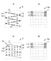
なお、制御部80は、レゾナントスキャナー15の発振周波数に合わせて出力されるトリガ信号(同期信号)に基づき、受光素子56で眼底からの反射光を読み取るタイミングを決定する。図6(a)にフレームメモリ81aの説明図を示す。例えば、フレームメモリ81aはn行×m列で二次元配列された複数の入力部dnm(n=1、2・・・、m=1、2・・・)を持ち、各入力部dnmには、受光素子56で読み取られた反射光の受光信号に基づく輝度情報が順次蓄積される。例えば制御部80は、レゾナントスキャナー15の1走査(走査線)ごとに出力される同期信号をトリガ信号として、所定のサンプリング周波数のクロック信号を出力させ、クロック信号のタイミングに合わせて、眼底の反射光を受光素子56で取得する。トリガ信号が入力されると、制御部80はレゾナントスキャナー15の一往復の走査(走査線)で読み取られた信号(輝度情報)を1行目の入力部d1m(m=1、2・・・)に順次割り当てる。次のトリガ信号が入力されると、制御部80はレゾンナントスキャナー15の一往復の走査に連動して読み取られた信号(輝度情報)を2行目の入力部d2m(m=1、2・・・)に蓄積させる。このようにして走査線毎にフレームメモリ81に割り当てて行く。そして、フレームメモリ81aへの信号(輝度情報)の蓄積が完了すると、制御部80はレゾナントスキャナー15の往路と復路で読み取られた信号(輝度情報)を交互に重ね合わせるために、往路の画像領域と復路の画像領域を区分けする。
<Correcting the position of the shot image>
The control unit 80 determines the timing at which the light receiving element 56 reads the reflected light from the fundus based on the trigger signal (synchronization signal) output in accordance with the oscillation frequency of the resonant scanner 15. FIG. 6A shows an explanatory diagram of the frame memory 81a. For example, the frame memory 81a has a plurality of input units dnm (n = 1, 2,..., M = 1, 2,...) Two-dimensionally arranged in n rows × m columns. The luminance information based on the received light signal of the reflected light read by the light receiving element 56 is sequentially accumulated. For example, the control unit 80 outputs a clock signal having a predetermined sampling frequency using a synchronization signal output for each scanning (scanning line) of the resonant scanner 15 as a trigger signal, and reflects the fundus according to the timing of the clock signal. Light is acquired by the light receiving element 56. When the trigger signal is input, the control unit 80 inputs the signal (luminance information) read by one reciprocal scanning (scanning line) of the resonant scanner 15 to the input unit d1m (m = 1, 2,...) In the first row. ) Sequentially. When the next trigger signal is input, the control unit 80 outputs the signal (luminance information) read in conjunction with one-way scanning of the resonant scanner 15 to the input unit d2m (m = 1, 2,.・ ・). In this way, each scanning line is allocated to the frame memory 81. Then, when the accumulation of the signal (luminance information) in the frame memory 81a is completed, the control unit 80 superimposes the signal (luminance information) read in the forward path and the backward path of the resonant scanner 15 in order to superimpose the signal (luminance information) in the forward path. And the image area of the return path.

なおミラー15aの振り角は、制御部80で直接制御されるものではない。そこで制御部80は、フレームメモリ81aの入力欄dnmを所定の位置で2分割して、往路の画像領域と復路の画像領域とみなす。つまり図6(a)では、制御部80は、基準位置Oを介して紙面左側を往路の画像領域D1,紙面右側が復路の画像領域D2とみなす。そして、走査線の異なる往路の画像領域D1と復路の画像領域D2とを重ね合わせるために、制御部80は、基準位置Oを軸に画像領域D1(又は画像領域D2)の信号(輝度情報)の並びを反転させる。そして画像領域D1の画素と画像領域D2の信号(輝度情報)を走査線毎に交互に並べて、モニタ70に表示される第1撮影画像の元となる基準画像を形成する。   The swing angle of the mirror 15a is not directly controlled by the control unit 80. Therefore, the control unit 80 divides the input field dnm of the frame memory 81a into two at a predetermined position, and regards it as the forward image area and the backward image area. That is, in FIG. 6A, the control unit 80 regards the left side of the paper as the forward image area D1 and the right side of the paper as the backward image area D2 via the reference position O. Then, in order to superimpose the forward image area D1 and the backward image area D2 with different scanning lines, the control unit 80 outputs a signal (luminance information) of the image area D1 (or image area D2) with the reference position O as an axis. Reverse the sequence of. Then, the pixels of the image area D1 and the signals (luminance information) of the image area D2 are alternately arranged for each scanning line to form a reference image that is the basis of the first captured image displayed on the monitor 70.

ところで、レゾナントスキャナー15のミラー15aの振り角は、駆動部15aの駆動状態の変化に依存する。その為、同期信号とミラー15aの振り角との間に位相差が生じてしまうと、図6(b)に示すように、トリガ信号に基づく画像の取り込み開始位置が、走査線方向にずれてしまう。この場合、画像領域81aを2分割する位置を基準位置Oとして、往路の画像と復路の画像を区分けすると、実際の境界位置O1と基準位置Oとの間にずれが生じる。   By the way, the swing angle of the mirror 15a of the resonant scanner 15 depends on a change in the driving state of the driving unit 15a. Therefore, if a phase difference occurs between the synchronization signal and the swing angle of the mirror 15a, the image capture start position based on the trigger signal is shifted in the scanning line direction as shown in FIG. 6B. End up. In this case, if the position where the image area 81a is divided into two is set as the reference position O and the forward image and the backward image are divided, a deviation occurs between the actual boundary position O1 and the reference position O.

同様にレゾナントスキャナー15の発振周波数が変化すると、図6(c)に示されるように、水平方向の画像のサイズが変化する。例えば、発振周波数が高くなると、一走査線当たりで読み取られる画素数が少なくなり画像が走査線方向に圧縮される。つまり一画素がカバーする範囲が広くなるため縮小系となる。一方、発振周波数が低くなると、走査線毎に読み取られる画素数が多くなり、画像が走査線方向に伸びたものになる。なお、図6(c)では画素数が減り、画像が圧縮される例を示している。この場合にも、仮の基準位置Oと、実際の往路の画像領域D1と復路の画像領域D2の境界位置O2との間にずれが生じる。そして、誤った基準位置Oに基づいて、画像領域D1(又は画像領域D2)の輝度情報の並びが反転され、基準画像が形成されると、副走査方向に隣り合う信号(輝度情報)間で歪が生じてしまい、画質が低下してしまう。   Similarly, when the oscillation frequency of the resonant scanner 15 changes, as shown in FIG. 6C, the size of the image in the horizontal direction changes. For example, when the oscillation frequency increases, the number of pixels read per scanning line decreases and the image is compressed in the scanning line direction. In other words, since the range covered by one pixel is widened, the reduction system is used. On the other hand, when the oscillation frequency is lowered, the number of pixels read for each scanning line increases, and the image extends in the scanning line direction. FIG. 6C shows an example in which the number of pixels is reduced and the image is compressed. Also in this case, a deviation occurs between the temporary reference position O and the boundary position O2 between the actual forward image area D1 and the backward image area D2. Then, when the arrangement of the luminance information in the image area D1 (or the image area D2) is inverted based on the erroneous reference position O and a reference image is formed, between signals (luminance information) adjacent in the sub-scanning direction. Distortion occurs and image quality is degraded.

なおレゾンナントスキャナー15の往復走査で1画像を生成する際に生じる基準位置Oのずれは、レゾナントスキャナー15の発振周波数が変化するほど現れ易くなる。特に、波面補償光学系を備える眼底撮影装置では、細胞レベルの撮影画像を高速で取得することが求められており、基準位置Oのずれが生じやすくなるおそれが有る。
そこで、本実施形態では、往路の画像領域D1と復路の画像領域D1の境界に基準位置が正しく設定されるようにする。なお設定される基準位置は、基準位置情報として記憶部81に記憶される。
The deviation of the reference position O that occurs when one image is generated by the reciprocating scanning of the resonant scanner 15 is more likely to appear as the oscillation frequency of the resonant scanner 15 changes. In particular, a fundus imaging apparatus including a wavefront compensation optical system is required to acquire a cell-level captured image at high speed, and there is a possibility that the reference position O is likely to be shifted.
Therefore, in the present embodiment, the reference position is set correctly at the boundary between the forward image area D1 and the backward image area D1. The set reference position is stored in the storage unit 81 as reference position information.

図7に基準位置の設定のためのフローチャートを示す。まず、ステップS101で、レゾナントスキャナー15の一走査(走査線)毎に、受光素子56が眼底からの反射光を読み取って、輝度情報として入力欄dnmに蓄積する。この時、ガルバノミラー15は、副走査方向に走査されている。次にステップS102で、制御部80は、フレームメモリ81aを2分割する仮の基準位置Oを設定して、仮の往路画像領域D1と仮の復路画像領域D2に分ける。そして、ステップS103で、仮の往路画像領域D1から任意の特徴部位を抽出すると共に、仮の復路画像領域D2から、仮の往路画像領域D1で抽出された画像領域と相関の高い画像領域を検出する。   FIG. 7 shows a flowchart for setting the reference position. First, in step S101, for each scanning (scanning line) of the resonant scanner 15, the light receiving element 56 reads the reflected light from the fundus and accumulates it as luminance information in the input field dnm. At this time, the galvanometer mirror 15 is scanned in the sub-scanning direction. Next, in step S102, the control unit 80 sets a temporary reference position O that divides the frame memory 81a into two, and divides the frame memory 81a into a temporary forward image area D1 and a temporary backward image area D2. In step S103, an arbitrary characteristic part is extracted from the temporary outbound image area D1, and an image area highly correlated with the image area extracted in the temporary outbound image area D1 is detected from the temporary inbound image area D2. To do.

次にステップS104で、制御部80は、仮の往路画像領域D1で抽出された特徴部位の中心から仮の基準位置Oまでの距離ΔLと、仮の復路画像領域D2で抽出された特徴部位から仮の基準位置Oまでの距離Δrを求める。そして、次式を用いて実際の基準位置O1に対する仮の基準位置Oのずれ量Δdを求める。   Next, in step S104, the control unit 80 determines the distance ΔL from the center of the feature part extracted in the provisional forward path image area D1 to the provisional reference position O and the feature part extracted in the provisional return path image area D2. A distance Δr to the temporary reference position O is obtained. Then, a deviation amount Δd of the temporary reference position O with respect to the actual reference position O1 is obtained using the following equation.

Figure 0006217065
例えば、仮の基準位置Oに対して実際の基準位置O1が主走査方向(紙面右側)に距離Δdずれている場合、制御部80は、ステップS105で、各入力欄dnmの信号(輝度情報)の座標を距離Δd(紙面左側)シフトさせる補正をする。このような処理によって、レゾナントスキャナー15の往路と復路で読み取られた信号(輝度情報)に対して基準位置O1が正しく設定され、往路の画像領域D1と復路の画像領域D2が正しく設定される。そして上記の画像処理によって、往路の画像と復路の画像が合成されることで、基準画像が精度良く形成される。
Figure 0006217065
For example, when the actual reference position O1 is shifted from the temporary reference position O by the distance Δd in the main scanning direction (on the right side of the paper), the control unit 80 performs a signal (luminance information) of each input field dnm in step S105. Is corrected to shift the coordinates of [Delta] d by the distance [Delta] d (left side of the paper). By such processing, the reference position O1 is correctly set with respect to the signals (luminance information) read in the forward path and the backward path of the resonant scanner 15, and the forward image area D1 and the backward image area D2 are correctly set. Then, the reference image is formed with high accuracy by combining the forward image and the backward image by the above image processing.

なお以上のように基準画像が形成されたら、制御部80は基準画像を構成する信号(輝度情報)を順次読み出してモニタ70に表示させる。この時、本実施形態では、フレームメモリ81aの基準画像の情報は、一旦画像補正部81bで変換される。これにより、画像補正部81bの情報が順次出力されることで、基準画像に含まれる画素の歪が更に補正される。そして、ステップS106で、モニタ70に第1眼底画像が好適に表示されるようになる。   When the reference image is formed as described above, the control unit 80 sequentially reads out signals (luminance information) constituting the reference image and causes the monitor 70 to display them. At this time, in this embodiment, the reference image information in the frame memory 81a is once converted by the image correction unit 81b. As a result, the information of the image correction unit 81b is sequentially output, so that the distortion of the pixels included in the reference image is further corrected. In step S106, the first fundus image is suitably displayed on the monitor 70.

第2撮影画像70bにおける異なる領域(撮影箇所)を観察したい場合は、図4(c)に示されるように、コントロール部92の操作で、第2撮影画像70b上に表示されたマークMを適宜移動させる。なおカーソルをモニタ70に表示させ、カーソルにてマークMが適宜移動される構成としてもよい。また第2撮影画像70bにおいて、第1撮影画像70aの撮影が完了した領域(マークMが表示されていた範囲)の表示状態を変えることで、第2撮影画像70b上で第1撮影画像70aの撮影の完了を視覚的に分かり易く示しても良い。以上のようにして、異なる第1撮影画像の撮影位置が指定されると、制御部80は新しく指定された第1撮影画像の撮影位置に対応するガルバノスキャナー40の条件を求め、ガルバノスキャナー40の駆動制御をする。   When it is desired to observe a different region (photographed place) in the second photographed image 70b, the mark M displayed on the second photographed image 70b is appropriately set by operating the control unit 92 as shown in FIG. Move. The cursor may be displayed on the monitor 70 and the mark M may be appropriately moved by the cursor. Further, in the second photographed image 70b, by changing the display state of the area where the photographing of the first photographed image 70a has been completed (the range in which the mark M is displayed), the first photographed image 70a on the second photographed image 70b is changed. The completion of shooting may be shown visually in an easily understandable manner. As described above, when the photographing position of the different first photographed image is designated, the control unit 80 obtains the condition of the galvano scanner 40 corresponding to the newly designated photographing position of the first photographed image. Drive control.

<画像補正>
また本実施形態のように、レゾナントミラー15の主走査と、ガルバノスキャナー40で副走査とが組合せられる場合、ガルバノスキャナー40は副走査方向に等速直線運動で移動されることが動作の安定性上で好ましい。しかしガルバノスキャナー40が等速で移動されると、主走査方向の各走査線の両端(左右位置)で形成される画素に歪が生じる場合がある。図8に眼底の撮影領域とガルバノスキャナー40の副走査による走査線との関係の説明図を示す。なおここでは説明の便宜上、レゾナントスキャナー15の主走査による走査線の記載は省略する。図8(a)は、眼底の撮影領域に対するガルバノスキャナー40の走査軌跡の説明図であり、撮影領域R、ガルバノスキャナー40の各走査線Ln(n=1、2、・・・、m)、ガルバノスキャナー40の走査線に連動して受光素子56で画素が取得されるサンプリングポイントPn(n=1、2、3、・・・、m)である。図8(b)はモニタ70上の第1撮影画像の表示領域であり、各サンプリングポイントPn(n=1、2、3、・・・、m)で読み取られた画素の表示領域rが走査線Ln(n=1、2、・・・、m)毎に用意されている。
<Image correction>
Further, when the main scanning of the resonant mirror 15 and the sub-scanning by the galvano scanner 40 are combined as in the present embodiment, the galvano scanner 40 is moved by a constant linear motion in the sub-scanning direction. Preferred above. However, when the galvano scanner 40 is moved at a constant speed, distortion may occur in pixels formed at both ends (left and right positions) of each scanning line in the main scanning direction. FIG. 8 is an explanatory diagram showing the relationship between the fundus imaging region and the scanning lines by sub-scanning of the galvano scanner 40. Here, for convenience of explanation, description of scanning lines by main scanning of the resonant scanner 15 is omitted. FIG. 8A is an explanatory diagram of the scanning trajectory of the galvano scanner 40 with respect to the fundus imaging region. Each scanning line Ln (n = 1, 2,..., M) of the imaging region R and the galvano scanner 40 is shown in FIG. This is a sampling point Pn (n = 1, 2, 3,..., M) at which pixels are acquired by the light receiving element 56 in conjunction with the scanning line of the galvano scanner 40. FIG. 8B shows the display area of the first photographed image on the monitor 70, and the display area r of the pixel read at each sampling point Pn (n = 1, 2, 3,..., M) is scanned. Prepared for each line Ln (n = 1, 2,..., M).

例えば、図8(a)に示されるように、ガルバノスキャナー40の走査線L1と、走査線L2を見たときに、副走査方向に隣り合うサンプリングポイントP1とP6で読み取られる信号(輝度情報)は離散的になり、副走査方向に隣り合うサンプリングポイントP6とP7で読み取られる信号(輝度情報)は重複してしまう。この場合、モニタ70に加算平均画像を表示させる場合には、眼底画像の画質がさらに低下するおそれが有る。また眼底の輝度値の分布状態と、モニタ70の第1撮影画像の輝度値の分布状態との間に差があると、トラッキングを行う際に誤動作の原因にもなり得る。一方で、これを避けるために、走査線の端部で読み取られた信号(輝度情報)を捨てて、誤差が少ない走査線の中央部の輝度情報のみで第1撮影画像を形成することも考えられるが、一度の撮影で表示される第1撮影画像の画角が小さくなり、撮影回数と撮影時間が増加し、患者の負担となることが懸念される。また、このような走査線の端部でのし輝度情報のばらつきは、第1撮影画像を出来るだけ早く形成するために、ガルバノスキャナー40の速度を上げた場合に顕著になるおそれがある。   For example, as shown in FIG. 8A, when the scanning lines L1 and L2 of the galvano scanner 40 are viewed, signals (luminance information) read at sampling points P1 and P6 adjacent in the sub-scanning direction. Becomes discrete, and signals (luminance information) read at sampling points P6 and P7 adjacent in the sub-scanning direction overlap. In this case, when the addition average image is displayed on the monitor 70, the image quality of the fundus image may be further deteriorated. Further, if there is a difference between the distribution state of the luminance value of the fundus and the distribution state of the luminance value of the first captured image of the monitor 70, it may cause a malfunction when performing tracking. On the other hand, in order to avoid this, it is also possible to discard the signal (luminance information) read at the end of the scanning line and form the first photographed image only with the luminance information at the center of the scanning line with little error. However, there is a concern that the angle of view of the first photographed image displayed by one photographing is reduced, the number of photographing times and the photographing time are increased, and this is a burden on the patient. In addition, such variation in the luminance information at the end of the scanning line may become conspicuous when the speed of the galvano scanner 40 is increased in order to form the first captured image as soon as possible.

そこで、本実施形態では、図8(c)に示されるように、副走査方向に隣り合うサンプリングポイントPnで読み取られた信号(輝度情報)を平均化して第1撮影画像70aを構成する新たな信号(輝度情報)を生成する。例えば、図8(c)において、制御部80は、サンプリングポイントP1とP6で読み取られた信号(輝度情報)の平均値を求めて、、図8(d)に示されるように、モニタ70の所要の表示領域rに表示させる。このようにすると、ガルバノスキャナー40の等速直線運動による左右位置での画素の偏りの影響が抑えられる。また、画素の輝度の平均化によって、副走査方向に隣り合う位置で取得された輝度情報に差(ズレ)が生じていた場合に、そのズレ量が平均化の処理により低減される。これにより、モニタに第1撮影画像70aが精度良く表示されるようになる。   Therefore, in the present embodiment, as shown in FIG. 8C, a new signal that configures the first captured image 70a by averaging the signals (luminance information) read at the sampling points Pn adjacent in the sub-scanning direction. A signal (luminance information) is generated. For example, in FIG. 8C, the control unit 80 obtains an average value of the signals (luminance information) read at the sampling points P1 and P6, and as shown in FIG. It is displayed in the required display area r. In this way, the influence of pixel bias at the left and right positions due to the constant velocity linear motion of the galvano scanner 40 can be suppressed. Further, when a difference (deviation) occurs in the luminance information acquired at positions adjacent to each other in the sub-scanning direction due to the averaging of the luminance of the pixels, the deviation amount is reduced by the averaging process. As a result, the first captured image 70a is accurately displayed on the monitor.

なお、以上のような輝度情報の平均化処理は、少なくとも誤差が含まれる可能性のある第1撮影画像70aの左右位置の所定領域に含まれる輝度情報を対象として行われても良い。画像処理が必要な領域に対してのみ行われることで、より効率よく画像が形成される。また上記では副走査方向に隣り合う信号(輝度情報)の平均値を求めているが、これ以外にも、隣り合う信号(輝度情報)に基づいて新しい輝度値を持つ信号が生成されれば良い。例えば、加算処理等の演算によって新しい輝度値を持つ信号(輝度情報)が生成されても良い。   Note that the luminance information averaging process as described above may be performed on luminance information included in a predetermined region in the left and right positions of the first captured image 70a that may contain at least an error. By performing the image processing only on the area that requires image processing, an image can be formed more efficiently. In the above description, the average value of signals (luminance information) adjacent in the sub-scanning direction is obtained, but in addition to this, a signal having a new luminance value may be generated based on the adjacent signals (luminance information). . For example, a signal (luminance information) having a new luminance value may be generated by an operation such as addition processing.

<画像の歪補正>
また上記では、装置の駆動時に画像処理で第1撮影画像の歪補正をする例を説明した。これ以外にも、レゾナントスキャナー15の検知信号を用いて、第1撮影画像の歪を補正することができる。つまり上述の画像処理による歪補正では、補正チャートの情報を基準位置情報として予め取得する必要がある。その為、撮影の途中でレゾナントスキャナー15の振り角に変化が生じ、第1撮影画像に再度歪が生じた場合には、補正チャートの取り直しが必要となる。そこで、輝度情報と共にレゾナントスキャナー15の走査角度の情報(走査位置信号)を取得する。そして走査位置信号から、サンプリングポイントpn(n=1、2、・・・、m)毎に走査角度の変化量を求め、サンプリングポイントpn毎の走査角度の変化量が一定値となるように、取得された輝度情報の走査角度の情報を補正する。このようにすると、撮影の途中でレゾナントスキャナー15の振り角に変化が生じたとしても、変化量の影響による画像の歪が抑えられて、モニタ70に第1撮影画像を継続して精度良く表示できる。
<Image distortion correction>
In the above description, the example in which the distortion of the first captured image is corrected by image processing when the apparatus is driven has been described. In addition to this, it is possible to correct the distortion of the first captured image using the detection signal of the resonant scanner 15. That is, in the distortion correction by the above-described image processing, it is necessary to previously acquire correction chart information as reference position information. For this reason, if the swing angle of the resonant scanner 15 changes during shooting and the first shot image is distorted again, the correction chart needs to be read again. Therefore, information on the scanning angle of the resonant scanner 15 (scanning position signal) is acquired together with the luminance information. Then, from the scanning position signal, the amount of change of the scanning angle is obtained for each sampling point pn (n = 1, 2,..., M), and the amount of change of the scanning angle for each sampling point pn becomes a constant value. The scanning angle information of the acquired luminance information is corrected. In this way, even if a change occurs in the swing angle of the resonant scanner 15 during shooting, image distortion due to the amount of change is suppressed, and the first shot image is continuously displayed on the monitor 70 with high accuracy. it can.

以下、第2変用例の眼科撮影装置を説明する。図9は、レゾナントミラー15の走査軌跡とサンプリングポイントpnとの関係の説明図である。ここで、サンプリングポイントpn、走査角度の変化量を求める際の基準となる直線状の走査軌跡(基準ライン)line、走査位置信号に基づき取得されたレゾナントスキャナー15の正弦波状の走査軌跡(測定ライン)rezとする。   Hereinafter, the ophthalmologic photographing apparatus according to the second modification will be described. FIG. 9 is an explanatory diagram of the relationship between the scanning trajectory of the resonant mirror 15 and the sampling point pn. Here, the sampling point pn, the linear scanning trajectory (reference line) line serving as a reference when obtaining the amount of change in the scanning angle, and the sinusoidal scanning trajectory (measurement line) of the resonant scanner 15 acquired based on the scanning position signal. ) Rez.

本実施形態では、上述の眼科撮影装置の駆動部15bに、ミラー15aの振り角を検知するための図示を略す検知部を取り付ける。検知部は、駆動部15bの電圧信号から、サンプリングポイントpn(n=1、2、・・、m)毎にレゾナントスキャナー15の走査位置信号を取得する。そして走査位置信号は輝度情報に関連付けられてメモリ81に記憶される。なお、基準ラインlineは、第1撮影画像の画角と走査速度によって走査角度[deg]を決定し、サンプリングポイントpn毎の走査角度の変化量を一定(a0)とすることで得られる直線波形の情報であり、予めメモリ81に記憶される。なお基準ラインlineのように、サンプリングポイントpn毎に、走査角度が等間隔で変化すると、眼底の反射光による輝度情報が一定の間隔で取得されるようになる。そこで、第2変用例では、メモリ81に記憶された基準レベルlineと測定ラインrezを比較し、レゾナントスキャナー15aの走査角度の変化量を求める。第1撮影画像を形成する輝度情報の位置を、走査角度の変化量に基づき補正することで、レゾナントスキャナー15の速度変化に伴い生じる第1撮影画像の歪を取り除くことができる。   In the present embodiment, a detection unit (not shown) for detecting the swing angle of the mirror 15a is attached to the drive unit 15b of the ophthalmologic photographing apparatus described above. The detection unit acquires a scanning position signal of the resonant scanner 15 for each sampling point pn (n = 1, 2,..., M) from the voltage signal of the driving unit 15b. The scanning position signal is stored in the memory 81 in association with the luminance information. Note that the reference line line is a linear waveform obtained by determining the scanning angle [deg] based on the angle of view and the scanning speed of the first captured image and making the amount of change in the scanning angle for each sampling point pn constant (a0). And is stored in the memory 81 in advance. If the scanning angle changes at equal intervals for each sampling point pn as in the reference line line, luminance information by reflected light from the fundus is acquired at regular intervals. Therefore, in the second modification, the reference level line stored in the memory 81 and the measurement line rez are compared to determine the amount of change in the scanning angle of the resonant scanner 15a. By correcting the position of the luminance information forming the first captured image based on the amount of change in the scanning angle, it is possible to remove the distortion of the first captured image caused by the change in the speed of the resonant scanner 15.

以上の構成を備える第2変用例の眼科撮影装置を説明する。図10は図9の拡大図である。先ず、制御部80は、走査部材の駆動制御で眼底に対して照明光を二次元的に走査させ、眼底からの反射光をサンプリングポイントpnに合わせて受光素子56で受光して光電変換する。また制御部80は検知の検知結果から、サンプリングポイントpn毎にレゾナントスキャナー15の走査位置信号を取得する。この時、レゾンナントスキャナー15の走査軌跡(測定ラインrez)は正弦波状に変化する。その為、図10に示されるように、サンプリングポイント毎に、走査角度[deg]の変化量a1、a2、・・・が変わる。この例では、基準ラインlineに対して、a1/a0、a2/a0、・・・のように走査角度[deg]の変化量に差が生じる。この場合、第1撮影画像を生成するために、輝度情報を画素としてモニタ70上に等間隔で配置する画像処理をすると、第1撮影画像の中央部と周辺部とで画像の歪みが生じてしまう。つまり、レゾナントスキャナー15の走査角度が基準である0[deg]から離れるにつれて、走査角度の移動量が小さくなり、眼底から輝度情報を取得する間隔が狭くなる。このように取得された輝度情報をモニタ70に等間隔で並べる処理をすると、第1撮影画像の中央部に対して周辺部が伸びたような画像が表示されてしまう。   The ophthalmologic photographing apparatus of the second modification example having the above configuration will be described. FIG. 10 is an enlarged view of FIG. First, the controller 80 scans the fundus two-dimensionally with the driving control of the scanning member, receives light reflected from the fundus by the light receiving element 56 in accordance with the sampling point pn, and performs photoelectric conversion. Further, the control unit 80 acquires the scanning position signal of the resonant scanner 15 for each sampling point pn from the detection result. At this time, the scanning trajectory (measurement line rez) of the resonant scanner 15 changes in a sine wave shape. Therefore, as shown in FIG. 10, the change amounts a1, a2,... Of the scan angle [deg] change for each sampling point. In this example, there is a difference in the change amount of the scanning angle [deg] with respect to the reference line line, such as a1 / a0, a2 / a0,. In this case, when image processing is performed in which luminance information is arranged as pixels on the monitor 70 at equal intervals in order to generate the first captured image, image distortion occurs at the central portion and the peripheral portion of the first captured image. End up. That is, as the scanning angle of the resonant scanner 15 moves away from 0 [deg], which is the reference, the amount of movement of the scanning angle decreases, and the interval for acquiring luminance information from the fundus decreases. When the luminance information acquired in this way is arranged on the monitor 70 at equal intervals, an image in which the peripheral portion extends from the central portion of the first captured image is displayed.

そこで、本実施形態では、サンプリングポイントpn(n=1、2、・・・、m)毎に、基準レベルlineの角度変化量の基準値a0に対する測定ラインrezの角度変化量の比率を求める。そして角度変化量の比率が一定となるように、第1撮影画像を形成する信号を求める画像処理をする。つまり図10のサンプリングポイントp1で取得された輝度情報に対しては、a1/a0だけ角度[deg]の補正を行い、サンプリングポイントp2で取得された輝度情報に対しては、a2/a0だけ角度[deg]を補正する。このようにすると、特に第1撮影画像の周辺部に生じる歪が抑えられる。なお上記の補正では、基準レベルlineと測定ラインrezの周波数は等しく、基準レベルlineと測定ラインlineの走査角度0[deg]は一致されているとする。   Therefore, in the present embodiment, for each sampling point pn (n = 1, 2,..., M), the ratio of the angle change amount of the measurement line rez to the reference value a0 of the angle change amount of the reference level line is obtained. Then, image processing is performed to obtain a signal for forming the first captured image so that the ratio of the angle change amount is constant. That is, for the luminance information acquired at the sampling point p1 in FIG. 10, the angle [deg] is corrected by a1 / a0, and for the luminance information acquired at the sampling point p2, the angle is a2 / a0. Correct [deg]. In this way, distortion that occurs particularly in the periphery of the first captured image is suppressed. In the above correction, the frequencies of the reference level line and the measurement line rez are equal, and the scanning angle 0 [deg] of the reference level line and the measurement line line is the same.

図11に、信号(画素)の補正量の説明図を示す。例えば走査の経過時間が37.5μsの時、モニタ70上で本来5.0μmの位置に置かれる信号(画素)は、約4.8μの位置に置かれる。走査の経過時間が45.0μsの時、本来8.0μmの位置に置かれる信号(画素)は約6.4μmの位置に置かれる。このように信号(輝度情報)の表示位置の補正によって画像の歪が抑えられる。   FIG. 11 is an explanatory diagram of the signal (pixel) correction amount. For example, when the elapsed time of scanning is 37.5 μs, the signal (pixel) originally placed at a position of 5.0 μm on the monitor 70 is placed at a position of about 4.8 μm. When the elapsed time of scanning is 45.0 μs, a signal (pixel) originally placed at a position of 8.0 μm is placed at a position of about 6.4 μm. In this way, image distortion can be suppressed by correcting the display position of the signal (luminance information).

図12に、本実施形態の画像処理による歪補正前と歪補正後の画像の比較例を示す。図12(a)の歪補正前では第1撮影画像の左右端部に画像の乱れが生じている。一方、図12(b)の歪補正後では、第1撮影画像の左右端部の乱れが抑えられていることが分かる。   FIG. 12 shows a comparative example of images before and after distortion correction by image processing according to the present embodiment. Before the distortion correction in FIG. 12A, image distortion occurs at the left and right ends of the first captured image. On the other hand, after the distortion correction of FIG. 12B, it can be seen that the disturbance of the left and right ends of the first captured image is suppressed.

なお上記では走査部材(レゾナントスキャナー)の振り角の変化量を求め、取得された輝度情報(画素)の位置補正(角度補正)をしている。これ以外にも、レゾナントスキャナーの走査位置信号の検出結果に基づき、サンプリング(サンプリングクロック)の周波数を変化させて、受光素子56で輝度情報を取り込むタイミングを調節することで、画像の歪を抑えることができる。なおサンプリング周波数の変調にはFM変調など、周知の周波数変調方式が用いられる。例えば、図13に示すように、検出部でレゾナントスキャナー15aの1周期分(T1)の波形変化を検出して、次の1周期(T2)で、周期T1で取得された波形変化に基づき、サンプリング周波数を周波数変調させて、輝度情報を取得するタイミングを調節する。具体的には、走査角度の基準である0度から、走査角度が大きくなる(離れる)につれて、受光素子56で輝度情報を取得するタイミング(サンプリングポイントの間隔)を遅くする。つまり周波数を低くする処理をする。このような処理により、レゾナントスキャナー15の速度変化によらず、眼底の輝度情報が一定間隔で取得されるようになる。その為、上述のような画像処理による補正をする事無く、効率よく歪が抑制された第1撮影画像をモニタ70に表示される。   In the above description, the change amount of the swing angle of the scanning member (resonant scanner) is obtained, and the position correction (angle correction) of the acquired luminance information (pixel) is performed. In addition, the distortion of the image can be suppressed by changing the sampling (sampling clock) frequency based on the detection result of the scanning position signal of the resonant scanner and adjusting the timing at which the light receiving element 56 takes in the luminance information. Can do. For the modulation of the sampling frequency, a known frequency modulation method such as FM modulation is used. For example, as shown in FIG. 13, the detection unit detects a waveform change for one period (T1) of the resonant scanner 15a, and in the next one period (T2), based on the waveform change acquired at the period T1, The timing at which luminance information is acquired is adjusted by frequency-modulating the sampling frequency. Specifically, the timing (sampling point interval) at which the light receiving element 56 obtains luminance information is delayed as the scanning angle increases (separates) from 0 degrees which is the reference of the scanning angle. That is, a process for lowering the frequency is performed. By such processing, the luminance information of the fundus is acquired at regular intervals regardless of the speed change of the resonant scanner 15. Therefore, the first captured image in which distortion is efficiently suppressed is displayed on the monitor 70 without performing correction by the above-described image processing.

なお上記では眼科撮影装置として、眼の収差を除去する波面補償部を持ち眼底を撮影する眼底撮影装置を例に挙げて説明した。これ以外にも共振スキャナーを持つ走査部材の走査で被検眼を照明し、眼からの反射光を受光素子で受光して眼の観察又は撮影を行う眼科装置に、本発明に掛かる構成が適用可能である。例えば、被検眼の角膜からの反射光を受光して、角膜内皮細胞等の観察又は撮影を行う眼科撮影装置等に適用される。   In the above description, the ophthalmologic photographing apparatus has been described by taking as an example a fundus photographing apparatus that has a wavefront compensation unit that removes eye aberrations and photographs the fundus. In addition to this, the configuration according to the present invention can be applied to an ophthalmologic apparatus that illuminates a subject's eye by scanning a scanning member having a resonance scanner and receives reflected light from the eye with a light receiving element to observe or photograph the eye. It is. For example, the present invention is applied to an ophthalmologic photographing apparatus that receives reflected light from the cornea of an eye to be examined and observes or photographs corneal endothelial cells and the like.

眼科撮影装置の外観図である。It is an external view of an ophthalmologic photographing apparatus. 眼科撮影装置の光学系の説明図である。It is explanatory drawing of the optical system of an ophthalmologic imaging apparatus. 眼科撮影装置の制御ブロック図である。It is a control block diagram of an ophthalmologic photographing apparatus. モニタの表示画面の例である。It is an example of the display screen of a monitor. 走査部材の走査状態の説明図である。It is explanatory drawing of the scanning state of a scanning member. フレームメモリの説明図である。It is explanatory drawing of a frame memory. 基準位置設定のフローチャートである。It is a flowchart of a reference position setting. 眼底撮影領域とガルバノスキャナーの副走査との関係の説明図である。It is explanatory drawing of the relationship between a fundus imaging area and sub-scanning of a galvano scanner. 第2変用例の歪補正の原理の説明図である。It is explanatory drawing of the principle of the distortion correction of the 2nd modification. 図9の歪補正の原理の説明図の拡大図である。FIG. 10 is an enlarged view of an explanatory diagram of the principle of distortion correction in FIG. 9. 第2変用例の歪補正の具体例である。It is a specific example of the distortion correction of the second modification example. 第2変用例の歪補正前後の撮影画像の例である。It is an example of the picked-up image before and after distortion correction of the 2nd modification example. 第3変用例の説明図である。It is explanatory drawing of the 3rd modification.

1 光源
10 視度補正部
56 受光素子
70 モニタ
80 制御部
81 記憶部
92 コントロール部
100 第1撮影ユニット
100a 第1照明光学系
100b 第1撮影光学系
110 波面補償部
200 第2撮影ユニット
500 眼科撮影装置
DESCRIPTION OF SYMBOLS 1 Light source 10 Diopter correction part 56 Light receiving element 70 Monitor 80 Control part 81 Storage part 92 Control part 100 1st imaging | photography unit 100a 1st illumination optical system 100b 1st imaging | photography optical system 110 Wavefront compensation part 200 2nd imaging | photography unit 500 Ophthalmic imaging | photography apparatus

Claims (1)

被検者眼の眼底を照明する照明光源を持つ照明光学系と、
前記照明光源の光束を前記眼底に対して走査線毎に往復振動させる共振型光スキャナーを持ち、前記光束によって眼底上を二次元走査するための走査部材と、
前記眼底からの反射光を受光して光電変換し所要の信号を出力する受光素子と、
を備える眼底撮影光学系と、
前記共振型光スキャナーによる往路走査と復路走査とが副走査方向に関して互いに異なる走査線で行われることにより眼底上が前記光束によって二次元走査されるように前記走査部材を制御する走査制御手段と、
1フレーム分の二次元走査において前記受光素子から出力される信号に基づいて眼底画像を得る画像生成手段と、を備え、
前記画像生成手段は、
前記走査線毎の走査部材の往復振動で取得された前記信号に基づく前記撮影画像を、前記往路走査による画素列と、前記復路走査による画素列と、に区分けするための基準位置を定め、
前記基準位置に基づいて区分けされた前記往路走査による素列を複数、副走査方向に並べることにより第1眼底画像データを生成すると共に、前記基準位置に基づいて区分けされた前記復路走査による素列を複数、副走査方向に並べることにより第2眼底画像データを生成し、
前記往路走査による複数の画素列を含む前記第1眼底画像データと、前記復路走査による複数の画素列を含む前記第2眼底画像データとの相関に基づいて、前記基準位置を補正し、
補正後の基準位置に基づいて区分けされた往路走査による複数の画素列による第1眼底画像データと、補正後の基準位置に基づいて区分けされた復路走査による複数の画素列による第2眼底画像データと、を合成して、合成眼底画像を得ることを特徴とする眼科撮影装置。
An illumination optical system having an illumination light source that illuminates the fundus of the subject's eye;
A resonance type optical scanner that reciprocally vibrates the luminous flux of the illumination light source with respect to the fundus for each scanning line, and a scanning member for two-dimensionally scanning the fundus with the luminous flux;
A light receiving element that receives reflected light from the fundus, photoelectrically converts the light, and outputs a required signal;
A fundus photographing optical system comprising:
Scanning control means for controlling the scanning member so that the fundus is two-dimensionally scanned by the light flux by performing forward scanning and backward scanning by the resonance type optical scanner with different scanning lines in the sub-scanning direction;
Image generating means for obtaining a fundus image based on a signal output from the light receiving element in two-dimensional scanning for one frame,
The image generating means includes
A reference position for dividing the captured image based on the signal acquired by the reciprocal vibration of the scanning member for each scanning line into a pixel row by the forward scanning and a pixel row by the backward scanning is determined,
A plurality of image Motoretsu by divided by said forward scanning on the basis of the reference position, to generate a first fundus image data by arranging the sub-scanning direction, image by divided by said backward scan on the basis of the reference position Generating second fundus image data by arranging a plurality of elementary rows in the sub-scanning direction;
Correcting the reference position based on a correlation between the first fundus image data including a plurality of pixel rows by the forward scanning and the second fundus image data including a plurality of pixel rows by the backward scanning ;
First fundus image data by a plurality of pixel columns by forward scanning divided based on the corrected reference position and second fundus image data by a plurality of pixel columns by backward scanning divided by the corrected reference position ophthalmologic photographing apparatus characterized by obtaining the synthesizes a synthesized fundus image.
JP2012215479A 2012-09-28 2012-09-28 Ophthalmic imaging equipment Active JP6217065B2 (en)

Priority Applications (1)

Application Number Priority Date Filing Date Title
JP2012215479A JP6217065B2 (en) 2012-09-28 2012-09-28 Ophthalmic imaging equipment

Applications Claiming Priority (1)

Application Number Priority Date Filing Date Title
JP2012215479A JP6217065B2 (en) 2012-09-28 2012-09-28 Ophthalmic imaging equipment

Publications (3)

Publication Number Publication Date
JP2014068703A JP2014068703A (en) 2014-04-21
JP2014068703A5 JP2014068703A5 (en) 2015-11-12
JP6217065B2 true JP6217065B2 (en) 2017-10-25

Family

ID=50744537

Family Applications (1)

Application Number Title Priority Date Filing Date
JP2012215479A Active JP6217065B2 (en) 2012-09-28 2012-09-28 Ophthalmic imaging equipment

Country Status (1)

Country Link
JP (1) JP6217065B2 (en)

Families Citing this family (11)

* Cited by examiner, † Cited by third party
Publication number Priority date Publication date Assignee Title
US9485383B2 (en) 2013-12-04 2016-11-01 Canon Kabushiki Kaisha Image based correction of distortion from a scanner
CN107106003B (en) * 2014-12-26 2019-03-12 株式会社尼康 Fundus imaging device
JP2017006424A (en) 2015-06-23 2017-01-12 キヤノン株式会社 Image generation apparatus and image generation method
JP6587430B2 (en) 2015-06-23 2019-10-09 キヤノン株式会社 Image generating apparatus and image generating method
US10709329B2 (en) 2015-07-30 2020-07-14 Canon Kabushiki Kaisha Image pickup apparatus and method of controlling image pickup apparatus
WO2017183191A1 (en) * 2016-04-22 2017-10-26 オリンパス株式会社 Image input device and image input method
US10536651B2 (en) 2016-08-03 2020-01-14 Canon Kabushiki Kaisha Inspection apparatus, method for controlling inspection apparatus, and program
JP6786297B2 (en) * 2016-08-03 2020-11-18 キヤノン株式会社 Inspection equipment, inspection equipment control methods, and programs
JP6788419B2 (en) * 2016-08-03 2020-11-25 キヤノン株式会社 Inspection equipment, inspection equipment control methods, and programs
JP6759080B2 (en) * 2016-11-28 2020-09-23 キヤノン株式会社 Image processing equipment, image forming equipment, image processing methods, and programs
JP7260426B2 (en) * 2019-07-11 2023-04-18 株式会社トプコン Optical coherence tomography device, control method thereof, optical measurement method, program, and storage medium

Family Cites Families (4)

* Cited by examiner, † Cited by third party
Publication number Priority date Publication date Assignee Title
JP3708277B2 (en) * 1997-03-19 2005-10-19 オリンパス株式会社 Scanning optical measuring device
JPH11225965A (en) * 1998-02-18 1999-08-24 Canon Inc Ophthalmology device
JP4281184B2 (en) * 1999-12-06 2009-06-17 株式会社島津製作所 Analysis equipment
JP2002098901A (en) * 2000-09-22 2002-04-05 Olympus Optical Co Ltd Scanning laser microscope

Also Published As

Publication number Publication date
JP2014068703A (en) 2014-04-21

Similar Documents

Publication Publication Date Title
JP6217065B2 (en) Ophthalmic imaging equipment
JP5259484B2 (en) Fundus photographing device
JP2014068704A (en) Ophthalmic photographing apparatus
JP6220248B2 (en) Ophthalmic apparatus and control method
JP5845608B2 (en) Ophthalmic imaging equipment
JP5543254B2 (en) Laser scanning imaging device
JP2012525184A (en) Improvement of scanning ophthalmoscope or improvement on scanning ophthalmoscope
JP2007014569A (en) Ophthalmologic imaging apparatus
JP6422629B2 (en) Fundus photographing device
JP5879830B2 (en) Fundus imaging device with wavefront compensation
US20200297209A1 (en) Imaging apparatus and control method therefor
JP6442960B2 (en) Fundus imaging device with wavefront compensation
US8777410B2 (en) Fundus photographing apparatus with wavefront compensation
US8085262B2 (en) Image display apparatus and image taking apparatus including the same
JP2011115301A (en) Fundus imaging apparatus
JP5545984B2 (en) Fundus imaging device with wavefront compensation
JP2013070941A (en) Ophthalmologic photographing apparatus
JP5727197B2 (en) Fundus imaging device with wavefront compensation
JP2019205816A (en) Imaging device and control method thereof
JP2013154063A (en) Ophthalmography device
JP2016123466A (en) Ocular fundus imaging device
JP2018000620A (en) Ophthalmological imaging apparatus
JP2005279121A (en) Apparatus for photographing eyeground
JP6866782B2 (en) Optical scanning imaging device and phase adjustment method
JP6436293B2 (en) Fundus imaging device with wavefront compensation

Legal Events

Date Code Title Description
A521 Request for written amendment filed

Free format text: JAPANESE INTERMEDIATE CODE: A523

Effective date: 20150925

A621 Written request for application examination

Free format text: JAPANESE INTERMEDIATE CODE: A621

Effective date: 20150925

A131 Notification of reasons for refusal

Free format text: JAPANESE INTERMEDIATE CODE: A131

Effective date: 20160628

A977 Report on retrieval

Free format text: JAPANESE INTERMEDIATE CODE: A971007

Effective date: 20160629

A521 Request for written amendment filed

Free format text: JAPANESE INTERMEDIATE CODE: A523

Effective date: 20160826

A131 Notification of reasons for refusal

Free format text: JAPANESE INTERMEDIATE CODE: A131

Effective date: 20170124

A521 Request for written amendment filed

Free format text: JAPANESE INTERMEDIATE CODE: A523

Effective date: 20170324

TRDD Decision of grant or rejection written
A01 Written decision to grant a patent or to grant a registration (utility model)

Free format text: JAPANESE INTERMEDIATE CODE: A01

Effective date: 20170829

A61 First payment of annual fees (during grant procedure)

Free format text: JAPANESE INTERMEDIATE CODE: A61

Effective date: 20170911

R150 Certificate of patent or registration of utility model

Ref document number: 6217065

Country of ref document: JP

Free format text: JAPANESE INTERMEDIATE CODE: R150

R250 Receipt of annual fees

Free format text: JAPANESE INTERMEDIATE CODE: R250

R250 Receipt of annual fees

Free format text: JAPANESE INTERMEDIATE CODE: R250

R250 Receipt of annual fees

Free format text: JAPANESE INTERMEDIATE CODE: R250

R250 Receipt of annual fees

Free format text: JAPANESE INTERMEDIATE CODE: R250