JP6215569B2 - Rolling bearing device - Google Patents
Rolling bearing device Download PDFInfo
- Publication number
- JP6215569B2 JP6215569B2 JP2013100068A JP2013100068A JP6215569B2 JP 6215569 B2 JP6215569 B2 JP 6215569B2 JP 2013100068 A JP2013100068 A JP 2013100068A JP 2013100068 A JP2013100068 A JP 2013100068A JP 6215569 B2 JP6215569 B2 JP 6215569B2
- Authority
- JP
- Japan
- Prior art keywords
- rolling bearing
- lubricating oil
- vibration wave
- unit
- pump
- Prior art date
- Legal status (The legal status is an assumption and is not a legal conclusion. Google has not performed a legal analysis and makes no representation as to the accuracy of the status listed.)
- Expired - Fee Related
Links
Images


Classifications
-
- F—MECHANICAL ENGINEERING; LIGHTING; HEATING; WEAPONS; BLASTING
- F16—ENGINEERING ELEMENTS AND UNITS; GENERAL MEASURES FOR PRODUCING AND MAINTAINING EFFECTIVE FUNCTIONING OF MACHINES OR INSTALLATIONS; THERMAL INSULATION IN GENERAL
- F16C—SHAFTS; FLEXIBLE SHAFTS; ELEMENTS OR CRANKSHAFT MECHANISMS; ROTARY BODIES OTHER THAN GEARING ELEMENTS; BEARINGS
- F16C33/00—Parts of bearings; Special methods for making bearings or parts thereof
- F16C33/30—Parts of ball or roller bearings
- F16C33/66—Special parts or details in view of lubrication
- F16C33/6637—Special parts or details in view of lubrication with liquid lubricant
- F16C33/6659—Details of supply of the liquid to the bearing, e.g. passages or nozzles
- F16C33/6674—Details of supply of the liquid to the bearing, e.g. passages or nozzles related to the amount supplied, e.g. gaps to restrict flow of the liquid
-
- F—MECHANICAL ENGINEERING; LIGHTING; HEATING; WEAPONS; BLASTING
- F16—ENGINEERING ELEMENTS AND UNITS; GENERAL MEASURES FOR PRODUCING AND MAINTAINING EFFECTIVE FUNCTIONING OF MACHINES OR INSTALLATIONS; THERMAL INSULATION IN GENERAL
- F16C—SHAFTS; FLEXIBLE SHAFTS; ELEMENTS OR CRANKSHAFT MECHANISMS; ROTARY BODIES OTHER THAN GEARING ELEMENTS; BEARINGS
- F16C19/00—Bearings with rolling contact, for exclusively rotary movement
- F16C19/02—Bearings with rolling contact, for exclusively rotary movement with bearing balls essentially of the same size in one or more circular rows
- F16C19/14—Bearings with rolling contact, for exclusively rotary movement with bearing balls essentially of the same size in one or more circular rows for both radial and axial load
- F16C19/16—Bearings with rolling contact, for exclusively rotary movement with bearing balls essentially of the same size in one or more circular rows for both radial and axial load with a single row of balls
-
- F—MECHANICAL ENGINEERING; LIGHTING; HEATING; WEAPONS; BLASTING
- F16—ENGINEERING ELEMENTS AND UNITS; GENERAL MEASURES FOR PRODUCING AND MAINTAINING EFFECTIVE FUNCTIONING OF MACHINES OR INSTALLATIONS; THERMAL INSULATION IN GENERAL
- F16C—SHAFTS; FLEXIBLE SHAFTS; ELEMENTS OR CRANKSHAFT MECHANISMS; ROTARY BODIES OTHER THAN GEARING ELEMENTS; BEARINGS
- F16C19/00—Bearings with rolling contact, for exclusively rotary movement
- F16C19/52—Bearings with rolling contact, for exclusively rotary movement with devices affected by abnormal or undesired conditions
-
- F—MECHANICAL ENGINEERING; LIGHTING; HEATING; WEAPONS; BLASTING
- F16—ENGINEERING ELEMENTS AND UNITS; GENERAL MEASURES FOR PRODUCING AND MAINTAINING EFFECTIVE FUNCTIONING OF MACHINES OR INSTALLATIONS; THERMAL INSULATION IN GENERAL
- F16C—SHAFTS; FLEXIBLE SHAFTS; ELEMENTS OR CRANKSHAFT MECHANISMS; ROTARY BODIES OTHER THAN GEARING ELEMENTS; BEARINGS
- F16C33/00—Parts of bearings; Special methods for making bearings or parts thereof
- F16C33/30—Parts of ball or roller bearings
- F16C33/58—Raceways; Race rings
- F16C33/583—Details of specific parts of races
- F16C33/586—Details of specific parts of races outside the space between the races, e.g. end faces or bore of inner ring
-
- F—MECHANICAL ENGINEERING; LIGHTING; HEATING; WEAPONS; BLASTING
- F16—ENGINEERING ELEMENTS AND UNITS; GENERAL MEASURES FOR PRODUCING AND MAINTAINING EFFECTIVE FUNCTIONING OF MACHINES OR INSTALLATIONS; THERMAL INSULATION IN GENERAL
- F16C—SHAFTS; FLEXIBLE SHAFTS; ELEMENTS OR CRANKSHAFT MECHANISMS; ROTARY BODIES OTHER THAN GEARING ELEMENTS; BEARINGS
- F16C33/00—Parts of bearings; Special methods for making bearings or parts thereof
- F16C33/30—Parts of ball or roller bearings
- F16C33/66—Special parts or details in view of lubrication
- F16C33/6637—Special parts or details in view of lubrication with liquid lubricant
- F16C33/664—Retaining the liquid in or near the bearing
- F16C33/6655—Retaining the liquid in or near the bearing in a reservoir in the sealing means
-
- F—MECHANICAL ENGINEERING; LIGHTING; HEATING; WEAPONS; BLASTING
- F16—ENGINEERING ELEMENTS AND UNITS; GENERAL MEASURES FOR PRODUCING AND MAINTAINING EFFECTIVE FUNCTIONING OF MACHINES OR INSTALLATIONS; THERMAL INSULATION IN GENERAL
- F16C—SHAFTS; FLEXIBLE SHAFTS; ELEMENTS OR CRANKSHAFT MECHANISMS; ROTARY BODIES OTHER THAN GEARING ELEMENTS; BEARINGS
- F16C41/00—Other accessories, e.g. devices integrated in the bearing not relating to the bearing function as such
- F16C41/004—Electro-dynamic machines, e.g. motors, generators, actuators
-
- F—MECHANICAL ENGINEERING; LIGHTING; HEATING; WEAPONS; BLASTING
- F16—ENGINEERING ELEMENTS AND UNITS; GENERAL MEASURES FOR PRODUCING AND MAINTAINING EFFECTIVE FUNCTIONING OF MACHINES OR INSTALLATIONS; THERMAL INSULATION IN GENERAL
- F16C—SHAFTS; FLEXIBLE SHAFTS; ELEMENTS OR CRANKSHAFT MECHANISMS; ROTARY BODIES OTHER THAN GEARING ELEMENTS; BEARINGS
- F16C41/00—Other accessories, e.g. devices integrated in the bearing not relating to the bearing function as such
- F16C41/008—Identification means, e.g. markings, RFID-tags; Data transfer means
-
- F—MECHANICAL ENGINEERING; LIGHTING; HEATING; WEAPONS; BLASTING
- F16—ENGINEERING ELEMENTS AND UNITS; GENERAL MEASURES FOR PRODUCING AND MAINTAINING EFFECTIVE FUNCTIONING OF MACHINES OR INSTALLATIONS; THERMAL INSULATION IN GENERAL
- F16N—LUBRICATING
- F16N13/00—Lubricating-pumps
-
- F—MECHANICAL ENGINEERING; LIGHTING; HEATING; WEAPONS; BLASTING
- F16—ENGINEERING ELEMENTS AND UNITS; GENERAL MEASURES FOR PRODUCING AND MAINTAINING EFFECTIVE FUNCTIONING OF MACHINES OR INSTALLATIONS; THERMAL INSULATION IN GENERAL
- F16N—LUBRICATING
- F16N13/00—Lubricating-pumps
- F16N13/22—Lubricating-pumps with distributing equipment
-
- F—MECHANICAL ENGINEERING; LIGHTING; HEATING; WEAPONS; BLASTING
- F16—ENGINEERING ELEMENTS AND UNITS; GENERAL MEASURES FOR PRODUCING AND MAINTAINING EFFECTIVE FUNCTIONING OF MACHINES OR INSTALLATIONS; THERMAL INSULATION IN GENERAL
- F16N—LUBRICATING
- F16N29/00—Special means in lubricating arrangements or systems providing for the indication or detection of undesired conditions; Use of devices responsive to conditions in lubricating arrangements or systems
-
- F—MECHANICAL ENGINEERING; LIGHTING; HEATING; WEAPONS; BLASTING
- F16—ENGINEERING ELEMENTS AND UNITS; GENERAL MEASURES FOR PRODUCING AND MAINTAINING EFFECTIVE FUNCTIONING OF MACHINES OR INSTALLATIONS; THERMAL INSULATION IN GENERAL
- F16N—LUBRICATING
- F16N9/00—Arrangements for supplying oil or unspecified lubricant from a moving reservoir or the equivalent
- F16N9/02—Arrangements for supplying oil or unspecified lubricant from a moving reservoir or the equivalent with reservoir on or in a rotary member
-
- F—MECHANICAL ENGINEERING; LIGHTING; HEATING; WEAPONS; BLASTING
- F16—ENGINEERING ELEMENTS AND UNITS; GENERAL MEASURES FOR PRODUCING AND MAINTAINING EFFECTIVE FUNCTIONING OF MACHINES OR INSTALLATIONS; THERMAL INSULATION IN GENERAL
- F16C—SHAFTS; FLEXIBLE SHAFTS; ELEMENTS OR CRANKSHAFT MECHANISMS; ROTARY BODIES OTHER THAN GEARING ELEMENTS; BEARINGS
- F16C19/00—Bearings with rolling contact, for exclusively rotary movement
- F16C19/02—Bearings with rolling contact, for exclusively rotary movement with bearing balls essentially of the same size in one or more circular rows
- F16C19/14—Bearings with rolling contact, for exclusively rotary movement with bearing balls essentially of the same size in one or more circular rows for both radial and axial load
- F16C19/16—Bearings with rolling contact, for exclusively rotary movement with bearing balls essentially of the same size in one or more circular rows for both radial and axial load with a single row of balls
- F16C19/163—Bearings with rolling contact, for exclusively rotary movement with bearing balls essentially of the same size in one or more circular rows for both radial and axial load with a single row of balls with angular contact
-
- F—MECHANICAL ENGINEERING; LIGHTING; HEATING; WEAPONS; BLASTING
- F16—ENGINEERING ELEMENTS AND UNITS; GENERAL MEASURES FOR PRODUCING AND MAINTAINING EFFECTIVE FUNCTIONING OF MACHINES OR INSTALLATIONS; THERMAL INSULATION IN GENERAL
- F16C—SHAFTS; FLEXIBLE SHAFTS; ELEMENTS OR CRANKSHAFT MECHANISMS; ROTARY BODIES OTHER THAN GEARING ELEMENTS; BEARINGS
- F16C19/00—Bearings with rolling contact, for exclusively rotary movement
- F16C19/02—Bearings with rolling contact, for exclusively rotary movement with bearing balls essentially of the same size in one or more circular rows
- F16C19/14—Bearings with rolling contact, for exclusively rotary movement with bearing balls essentially of the same size in one or more circular rows for both radial and axial load
- F16C19/18—Bearings with rolling contact, for exclusively rotary movement with bearing balls essentially of the same size in one or more circular rows for both radial and axial load with two or more rows of balls
- F16C19/181—Bearings with rolling contact, for exclusively rotary movement with bearing balls essentially of the same size in one or more circular rows for both radial and axial load with two or more rows of balls with angular contact
- F16C19/183—Bearings with rolling contact, for exclusively rotary movement with bearing balls essentially of the same size in one or more circular rows for both radial and axial load with two or more rows of balls with angular contact with two rows at opposite angles
- F16C19/184—Bearings with rolling contact, for exclusively rotary movement with bearing balls essentially of the same size in one or more circular rows for both radial and axial load with two or more rows of balls with angular contact with two rows at opposite angles in O-arrangement
-
- F—MECHANICAL ENGINEERING; LIGHTING; HEATING; WEAPONS; BLASTING
- F16—ENGINEERING ELEMENTS AND UNITS; GENERAL MEASURES FOR PRODUCING AND MAINTAINING EFFECTIVE FUNCTIONING OF MACHINES OR INSTALLATIONS; THERMAL INSULATION IN GENERAL
- F16C—SHAFTS; FLEXIBLE SHAFTS; ELEMENTS OR CRANKSHAFT MECHANISMS; ROTARY BODIES OTHER THAN GEARING ELEMENTS; BEARINGS
- F16C33/00—Parts of bearings; Special methods for making bearings or parts thereof
- F16C33/30—Parts of ball or roller bearings
- F16C33/66—Special parts or details in view of lubrication
- F16C33/6637—Special parts or details in view of lubrication with liquid lubricant
- F16C33/6688—Lubricant compositions or properties, e.g. viscosity
-
- F—MECHANICAL ENGINEERING; LIGHTING; HEATING; WEAPONS; BLASTING
- F16—ENGINEERING ELEMENTS AND UNITS; GENERAL MEASURES FOR PRODUCING AND MAINTAINING EFFECTIVE FUNCTIONING OF MACHINES OR INSTALLATIONS; THERMAL INSULATION IN GENERAL
- F16C—SHAFTS; FLEXIBLE SHAFTS; ELEMENTS OR CRANKSHAFT MECHANISMS; ROTARY BODIES OTHER THAN GEARING ELEMENTS; BEARINGS
- F16C33/00—Parts of bearings; Special methods for making bearings or parts thereof
- F16C33/72—Sealings
- F16C33/76—Sealings of ball or roller bearings
- F16C33/78—Sealings of ball or roller bearings with a diaphragm, disc, or ring, with or without resilient members
- F16C33/784—Sealings of ball or roller bearings with a diaphragm, disc, or ring, with or without resilient members mounted to a groove in the inner surface of the outer race and extending toward the inner race
- F16C33/7843—Sealings of ball or roller bearings with a diaphragm, disc, or ring, with or without resilient members mounted to a groove in the inner surface of the outer race and extending toward the inner race with a single annular sealing disc
- F16C33/7846—Sealings of ball or roller bearings with a diaphragm, disc, or ring, with or without resilient members mounted to a groove in the inner surface of the outer race and extending toward the inner race with a single annular sealing disc with a gap between the annular disc and the inner race
Landscapes
- Engineering & Computer Science (AREA)
- General Engineering & Computer Science (AREA)
- Mechanical Engineering (AREA)
- Rolling Contact Bearings (AREA)
Description
この発明は、工作機械や産業機械等に用いられる転がり軸受装置に関し、特に転がり軸受と給油ユニットの組み合わせからなる転がり軸受装置に関するものである。 The present invention relates to a rolling bearing device used for machine tools, industrial machines, and the like, and more particularly to a rolling bearing device composed of a combination of a rolling bearing and an oil supply unit.
給油ユニットを転がり軸受の内部に組み込んだ転がり軸受装置が従来から知られている(特許文献1参照)。この転がり軸受装置は、転がり軸受の相互に対向した軌道輪のうち、固定側の軌道輪の内径面に給油ユニットを装着している。給油ユニットは、潤滑油を溜めた潤滑油タンク、前記潤滑油タンクの潤滑油を軸受内部に吐出させるポンプ及び前記ポンプを駆動する発電機により構成される。軸受側の条件に応じてポンプを制御することにより吐出量を調整する手段を有する。 Conventionally, a rolling bearing device in which an oil supply unit is incorporated in a rolling bearing is known (see Patent Document 1). In this rolling bearing device, an oil supply unit is mounted on the inner diameter surface of the stationary bearing ring among the bearing rings facing each other of the rolling bearing. The oil supply unit includes a lubricating oil tank that stores lubricating oil, a pump that discharges the lubricating oil in the lubricating oil tank into the bearing, and a generator that drives the pump. Means for adjusting the discharge amount by controlling the pump according to the conditions on the bearing side is provided.
また、特許文献2に開示された転がり軸受装置も同様の給油ユニットを備えている。 Further, the rolling bearing device disclosed in Patent Document 2 includes a similar oil supply unit.
ところで、軸受近傍に内蔵された給油ユニットは、外部から遮断された環境に組み込まれる場合が多い。この給油ユニットの状態を監視し故障診断等を行うには、定期的な分解検査や外部に通信線等を引き出しておく必要がある。そのため運用面・組込み性に制限が生じる。 By the way, the oil supply unit built in the vicinity of the bearing is often incorporated in an environment shut off from the outside. In order to monitor the state of the refueling unit and perform failure diagnosis or the like, it is necessary to periodically disassemble and inspect communication lines and the like. As a result, there will be restrictions on operational aspects and embeddability.
そこで、この発明は、分解検査や外部に通信線等を引き出すことなく、組み込み状態のまま給油ユニットが正常に動作しているかどうかを把握することが可能な転がり軸受装置を提供することを課題とする。 Accordingly, an object of the present invention is to provide a rolling bearing device capable of grasping whether or not the refueling unit is operating normally without disassembling inspection or drawing out a communication line or the like outside. To do.
前記の課題を解決するために、この発明に係る転がり軸受装置は、転がり軸受と、潤滑油タンク、潤滑油タンクから潤滑油を吸引して吐出口から潤滑油を吐出するポンプ、ポンプを駆動する駆動部、駆動部に電気エネルギーを与える発電部を少なくとも備える給油ユニットの組み合わせからなり、前記給油ユニットを、転がり軸受の固定輪側部材又は転がり軸受に隣接する間座に取り付けた転がり軸受装置において、前記給油ユニットの動作情報を外部に発信する通信装置を給油ユニット内に設けたことを特徴とする。 In order to solve the above-described problems, a rolling bearing device according to the present invention drives a rolling bearing, a lubricating oil tank, a pump that sucks lubricating oil from the lubricating oil tank and discharges lubricating oil from a discharge port, and a pump. In a rolling bearing device comprising a drive unit, a combination of an oil supply unit including at least a power generation unit that gives electric energy to the drive unit, the oil supply unit is attached to a fixed ring side member of the rolling bearing or a spacer adjacent to the rolling bearing. A communication device for transmitting operation information of the fueling unit to the outside is provided in the fueling unit.
前記給油ユニットの構成部材をハウジング内に収納してユニット化することにより、ハウジングに対して脱着することができる。 The constituent members of the fuel supply unit are housed in the housing and unitized, so that they can be detached from the housing.
前記通信装置としては、振動波にて情報を伝える通信装置を使用することができる。 As the communication device, a communication device that transmits information by vibration waves can be used.
前記給油ユニットを複数設け、この複数の給油ユニットを同時に使用可能とする通信装置を設けてもよい。
この発明の転がり軸受装置は、工作機械、風車、鉄道に使用することができる。
A plurality of the oil supply units may be provided, and a communication device that can use the plurality of oil supply units simultaneously may be provided.
The rolling bearing device of the present invention can be used for machine tools, windmills, and railways.
この発明によれば、以上のように、給油ユニットの内部に給油ユニットの動作情報を外部に発信する通信装置を設けることにより、給油ユニットが正常に動作していることを組み込み状態で把握することが可能となる。また振動波で検出することにより、ワイヤレスでの情報の伝達が可能になる、組込み性の向上が可能になる、複数の給油ユニットを同時に使用することが可能になるといった利点がある。 According to the present invention, as described above, by providing a communication device for transmitting the operation information of the fueling unit to the outside inside the fueling unit, it is possible to grasp in a built-in state that the fueling unit is operating normally. Is possible. Further, by detecting with vibration waves, there are advantages that wireless information can be transmitted, the incorporation can be improved, and a plurality of fuel supply units can be used simultaneously.
以下、この発明の実施の形態を添付図面に基づいて説明する。
図1から図3に示す実施形態の転がり軸受装置10は、転がり軸受11、その軸方向の一端部に突き当てられた間座12及び間座12に組み込まれた給油ユニット13により構成され、回転軸14とハウジング15の間に組み込んで使用に供される。転がり軸受11の他端部にも他の間座16が突き当てられ、両方の間座12、16により転がり軸受11の軸方向の位置決めが行われる。この実施形態の回転軸14は水平に設置されている。
Embodiments of the present invention will be described below with reference to the accompanying drawings.
A rolling bearing
転がり軸受11は、回転側の軌道輪である内輪17、固定側の外輪18及びこれらの軌道輪の間に介在された所要数の転動体19、その転動体19を一定間隔に保持する保持器21により構成される、アンギュラ玉軸受、あるいは深溝玉軸受のいずれでもよい。転がり軸受11には、予め所望のグリースが封入され、間座16側の端部に、シール板22が装着されている。
The rolling bearing 11 includes an
間座12は、内輪側間座12aと外輪側間座12bとからなり、内輪側間座12aは回転軸14側に嵌合固定され、内輪17の一方の端面に突き当てられる。外輪側間座12bはハウジング15の内径面に嵌合固定され、外輪18の一方の端面に突き当てられる。他方の間座16も同様に回転軸14側及びハウジング15側に嵌合固定され、内輪17及び外輪18の他方の端面に突き当てられる。
The
前記給油ユニット13は、図3に示すように、円環状のハウジング24内に、円周方向に発電部41、充電部42、制御部43、駆動部44、ポンプ45、潤滑油タンク46、給油ユニット13の動作情報をワイヤレスで外部に発信する通信装置49等の諸部材を収納して構成される。
As shown in FIG. 3, the
給油ユニット13の円環状のハウジング24は、図2に示すように、転がり軸受11と反対側の面が開放された断面コの字形のハウジング本体24aと、このハウジング本体24aの開口部を閉塞し、ハウジング本体24aに対して着脱自在の蓋体24bとによって構成される。このハウジング本体24aと蓋体24bとは、PPS等の同種の熱可塑性樹脂材料からなる。
As shown in FIG. 2, the
ハウジング24の蓋体24bは、ハウジング本体24aに対し、ネジ24cにより固定され、ネジ24cを外して、蓋体24bを取り除くことにより、給油ユニット13全体を取外すことなく、ハウジング本体24a内に収納されている潤滑油タンク46に、潤滑油を補充することができる。
The
ハウジング本体24aの外周面は、外輪側間座12bの内径面に、接着剤によって接着固定されている。ハウジング本体24aを接着固定する接着剤は、エポキシ樹脂等を使用できる。
The outer peripheral surface of the housing
次に、ハウジング本体24a内に収納する潤滑油タンク46は、柔軟性を有する樹脂製の袋体46aからなり、円環状のハウジング24に沿って円弧状に配置されている。
Next, the lubricating
袋体46aには、ポンプ45と接続する吸込みチューブ45aを設けている。この吸込みチューブ45aは、袋体46aを熱溶着により形成する際に、袋体46aを形成する重ね合わせた樹脂シートの間に挟み込んで熱溶着することにより、袋体46aと一体化することができる。
The
また、袋体46aをブロー成形により形成する場合には、吸込みチューブ45aを袋体46aと一体にブロー成形することができる。
When the
潤滑油タンク46を形成する袋体46aの素材は、ナイロン、ポリエチレン、ポリエステル、ポリプロピレンなどを用いることができるが、袋体46a内に収容される潤滑油に侵されない素材であれば特に限定されない。
Nylon, polyethylene, polyester, polypropylene, or the like can be used as the material of the
潤滑油タンク46の袋体46aに充填する潤滑油の粘度は、あまり高いとポンプの負荷や電源への負担が大きくなるため、VG22程度が望ましい。
If the viscosity of the lubricating oil filled in the
ポンプ45には、潤滑油タンク46内の潤滑油を吸引する吸込みチューブ45aと、吸引した潤滑油を吐出する吐出チューブ45bを備え、吐出チューブ45bの先端の吐出ノズル45cから転がり軸受11の固定側の軌道輪と回転側の軌道輪の間に潤滑油が供給される。
The
ポンプ45を駆動させて、潤滑油タンク46内の潤滑油を吸引し、吐出チューブ45bの先端の吐出ノズル45cから転がり軸受11の固定側の軌道輪と回転側の軌道輪の間に潤滑油を供給し、所定量の潤滑油を供給した後に、ポンプ45を停止する。
The
ポンプ45を停止しても、ポンプ45内と配管内部は、潤滑油で満たされているため、潤滑油タンク46内の潤滑油がサイフォンの原理により引き出されて吐出ノズル45cから潤滑油が漏れ出すことがある。この漏れ出しを防止するために、ポンプ45の吐出配管に、潤滑油の漏れ出しを防止する漏れ出し防止機構を設けている。
Even if the
この漏れ出し防止機構としては、図3に示すように、吐出チューブ45bに開閉弁48を設け、ポンプ45が稼動する期間のみ、開閉弁48を開き、その他の状態では開閉弁48が閉じるようにしておく方法、あるいは、ポンプ45を駆動して給油動作を完了した後に、ポンプ45を逆転させて吐出配管内に空気を導入する方法などを採用することができる。
As shown in FIG. 3, an on-off
次に、潤滑油を供給するタイミング、即ち、ポンプ45の駆動のタイミングは、電力が充電部42のコンデンサに蓄電され、一定の電圧に達した時点で行なうことが可能である。発電効率との関係で蓄電時間が短い場合においては、蓄電電圧が一定の値に達した時点で抵抗器などに放電させ、ポンプ45の駆動のタイミングに、インターバルを設けてもよい。この場合、ポンプ45の駆動までの間に、充放電が繰り返されることになり、この充放電の回数でポンプ45の駆動のインターバルを管理してもよい。あるいは、蓄電電圧が一定の値に達した時点で、タイマ機能によりポンプ45の駆動のタイミングに、インターバルを設けてもよい。この場合は、前記の様な充放電を繰り返さない。
Next, the timing of supplying the lubricating oil, that is, the timing of driving the
ポンプ45の吸込み側に接続された吸込みチューブ45aは、潤滑油タンク46内に挿入され、潤滑油タンク46内の潤滑油が吸引される。
The
一方、吐出側に接続された吐出チューブ45bの先端には、転がり軸受の内部に潤滑油を吐出するための吐出ノズル45cを接続している。吐出ノズル45cの先端は、軸受内外輪の間で、内輪外周面に近い部分に配置することが望ましい。なお、吐出ノズル45cのノズル穴の内径寸法は、基油の粘度に起因する表面張力と、吐出量との関係により、適宜設定される。
On the other hand, a
円環状のハウジング24内には、潤滑油タンク46以外に、円周方向に発電部41、充電部42、制御部43、駆動部44、ポンプ45、給油ユニット13の動作情報をワイヤレスで外部に発信する通信装置49等を収納している。
In the
発電部41としては、例えば、図4に示すように、ゼーベック効果によって発電を行うものを使用することができる。即ち、転がり軸受装置10を使用した場合、転動体19(図1参照)との摩擦熱により内輪17と外輪18の温度が上昇する。通常、外輪18は機器のハウジング15に組み込まれるため熱伝導により放熱され、内輪17、外輪18の間で温度差が生じる。その温度が各熱伝導体52、53に伝導され、ゼーベック素子54の両端面に温度差を生じさせることにより、ゼーベック効果による発電を行う。
As the
ハウジング本体24aの内周面と外周面を貫通する熱伝導体52、53を設け、これら熱伝導体52、53の間にゼーベック素子54を介在したものを使用する場合、ハウジング本体24aの外周面を貫通する熱伝導体52が外輪側間座12bの内径面に接する面には、熱導電性を考慮した接着剤を使用することが望ましい。なお、外輪側の熱伝導体52の外径は、外輪側間座12bの内径寸法と同一にして、放熱効果が高くなるように密着させている。一方、内輪側の熱伝導体53の内径は、内輪側間座12aとは接していない。可能であれば、外輪側と内輪側の熱伝導体52、53の体積を等しくすることが望ましい。
When the
なお、外輪側間座12bの内径面と熱伝導体52の間、熱伝導体52とゼーベック素子54の間、ゼーベック素子54と内輪側の熱伝導体53の間には、熱伝導率及び密着性を高めるため、放熱グリースなどを塗布することが好ましい。放熱グリースは、一般的にシリコーンが主成分である。また、熱伝導体52、53は、熱伝導率の高い金属を使用する。例えば、銀、銅、金などが挙げられるがコスト面から、銅を使用する事が一般的である。なお、銅を主成分とする銅合金でもよい。また、銅を主成分とする焼結合金でもよい。
The thermal conductivity and adhesion between the inner diameter surface of the outer
発電部41は、前記のゼーベック効果によって発電を行うもののほか、図5、図6、図7に示すものを使用することができる。
The
図5に示すものは、転がり軸受装置10内に交番磁界が存在する場合に適用される。工作機等のビルトインスピンドル内部や大電力を扱う高周波機器の近傍では、漏れ磁束又は高周波の照射が発生する。この漏れ磁束を利用し電磁誘導により発電を行うものである。即ち、片側を開放したE形の鉄心55にコイル56を組み合わせることで効率よく交番磁界を捉え、電磁誘導による発電を行う。鉄心55の開放面に絶縁性基台57が取り付けられる。漏れ磁束の周波数が既知である場合は、鉄心55を除き漏れ磁束の周波数に共振するコイル56を用いるようにしてもよい。
The configuration shown in FIG. 5 is applied when an alternating magnetic field exists in the rolling
図6に示すものは、転がり軸受装置10内に振動が発生する場合に適用されるものである。即ち、固定側絶縁基板58、その上に配置された可動側絶縁基板59の対向面にそれぞれ多数の電極60を設け、固定側絶縁基板58の電極60にのみエレクトレット61を積層し、可動側絶縁基板59の電極60に対し空隙を設けて対向させる。可動側絶縁基板59は摺動装置62によって図中の矢印aの方向にのみ移動可能となる。
The configuration shown in FIG. 6 is applied when vibration occurs in the rolling
転がり軸受装置10に振動が発生すると、摺動装置62によって矢印aの方向に可動側絶縁基板59が振動する。このとき、固定側絶縁基板58及び可動側絶縁基板59の相対運動とエレクトレット61により、電極60間に静電誘導による電荷が発生する。この発生した電荷を外部に取り出すことにより発電を行う。
When vibration is generated in the rolling
図7に示すものも転がり軸受装置10内に振動が発生する場合に適用されるものである。即ち、固定側絶縁基板58と重り63の間に弾性のあるシート状の圧電体64を配置する。転がり軸受装置10に振動が発生すると、重り63と圧電体64により矢印aの方向に重り63が振動する。このとき、圧電体64にひずみが生じ誘電分極による起電力が発生する。その起電力を外部に取り出すことにより発電を行う。
7 is also applied when vibration is generated in the rolling
発電部41によって発電した電荷は、蓄電池やコンデンサなどの充電部42に蓄電される。コンデンサは、電気二重層コンデンサ(キャパシタ)を使用することが望ましい。
The electric charge generated by the
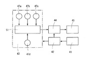
制御部43は、図8に示すように、例えば、軸受温度センサー47a、軸受回転センサー47b、潤滑油残量センサー47c、潤滑油温度センサー47d等のセンサーを備える。これらのセンサーから信号がCPU51に入力され、転がり軸受11の温度及びその回転状況に応じてポンプ45を自動制御し、潤滑油の供給量を調整する。
As shown in FIG. 8, the
通信装置49は、図1のように外輪側間座12bに取付けられる。また通信手段として振動波を用いることができる。振動波を用いることでワイヤレス化と組込み性の向上が図られる。
The
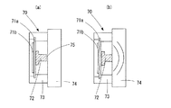
図9に振動波発生装置70を示す。図9(a)(b)において金属板71aに圧電体71bが貼りつけてあり、金属板71aを挟む圧電体71bの対向面側に打付け部72を取り付けてある。固定ケース73はこれらを支持し、更に振動波伝達媒体74に固定される。この時、打付け部72と振動波伝達媒体74の間に微小隙間75を設けてある。この装置の圧電体71bに電圧を印加すると圧電効果(逆圧電効果)により圧電体71bが、図9(b)のように機械的変形を起こす。それに伴い金属板71aも変形を起こし、打付け部72が振動波伝達媒体74に打付けられ、起震源となり振動波伝達媒体74の内部に振動波を生じさせる。この振動波は、振動波伝達媒体74の内部を伝搬する。なお実際の機器において振動波伝達媒体74は、図1における外輪側間座12b及び給油ユニット13を格納するハウジング24類に相当する。
FIG. 9 shows a
上記の方法によって得られる振動波による通信方法は、以下のようになる。
振動波は、図10のように、振動波伝達媒体74を挟み、振動波発生装置70と対向する位置に設けられた振動波検出器77により検出される。
A communication method using vibration waves obtained by the above method is as follows.
The vibration wave is detected by a
図10では波形発生装置76が発生した周波数に従い振動波発生装置70を駆動させ、任意の周波数を持つ振動波Aを発生させている。この振動波Aは、振動波伝達媒体74を通じて振動波検出器77まで伝搬される。振動波検出器77は、振動波Aを電気信号に変換する。Bは検出波形を示している。
In FIG. 10, the
以上の通信手段を使用すれば機器内部に組み込まれた給油ユニット13の動作状態をワイヤレスによって知ることができる。図10において、符号76は振動波Aをを発生させる波形発生装置、符号78は増幅器、符号74は振動波伝達媒体、符号77は検出器を示している。
If the above communication means is used, the operation state of the
その給油ユニット13の動作状態を具体的に把握する方法として以下の手段がある。ポンプ動作毎に振動波Aを発生させる。そして振動波Aを検出した回数を計数すれば潤滑剤の残り残量が把握可能になる。同時に給油ユニット13が正常に動作を行なっていることも確認できる。
As a method for specifically grasping the operation state of the
複数の給油ユニット13を同時に組み込んだ場合の通信手段は、図11のようになる。
The communication means when a plurality of
基本構成要素は図10と変わりないが、各装置に異なる周波数の信号を発生させる発振器76a,76bを持たせている。また検出側にフィルター79を設け、特定周波数の信号を抽出させている。この手段を用いることにより、特定の給油ユニットの状態を知ることが可能になる。
Although the basic components are the same as in FIG. 10, each device has oscillators 76a and 76b that generate signals of different frequencies. A
以上の機能を持たせた給油ユニット13を機器に組み込んだ転がり軸受装置10を図12に示す。図12は、給油ユニット13を使用したスピンドル(回転軸14)の一部を示している。振動波Aは、外輪側間座12b及びハウジング15を伝搬する。そして振動波Aは、ハウジング15に取付けられた振動波検出器77により検出させる。なお振動波Aの周波数は、転がり軸受11が発生する振動周波数及びスピンドルが14持つ固有振動数(共振周波数)とは異なる周波数とする。このような周波数にすることにより振動波発生装置が生じた振動の検出を容易とし、機器の不要な共振を防止する効果がある。
FIG. 12 shows a rolling
以上のように、給油ユニット13の内部に振動波による通信装置を設けることにより、電気的機能が正常に動作していることを組み込み状態で把握することが可能となる。また振動波で検出することにより、ワイヤレスで情報の伝達が可能になる、組込み性の向上が可能になる、複数の給油ユニット13を同時に使用することが可能になるといった利点がある
As described above, by providing the communication device using the vibration wave inside the
10 軸受装置
11 転がり軸受
12 間座
12a 内輪側間座
12b 外輪側間座
13 給油ユニット
14 回転軸
15 ハウジング
16 間座
17 内輪
18 外輪
19 転動体
21 保持器
22 シール板
24 ハウジング
24a ハウジング本体
24b 蓋体
24c ネジ
41 発電部
42 充電部
43 制御部
44 駆動部
45 ポンプ
45a 吸込みチューブ
45b 吐出チューブ
45c 吐出ノズル
46 潤滑油タンク
46a 袋体
46b 熱溶着部分
47a〜47d センサー
48 開閉弁
49 通信装置
51 CPU
52、53 熱伝導体
54 ゼーベック素子
55 鉄心
56 コイル
57 絶縁性基台
58 固定側絶縁基板
59 可動側絶縁基板
60 電極
61 エレクトレット
62 摺動装置
63 重り
64 圧電体
70 振動波発生装置
71a 金属板
71b 圧電体
72 打付け部
73 固定ケース
74 振動波伝達媒体
75 微小隙間
76a,76b 発振器
77 振動波検出器
79 フィルター
DESCRIPTION OF
52, 53
Claims (2)
The rolling bearing device according to claim 1 , which is used for a machine tool, a windmill, and a railway.
Priority Applications (5)
| Application Number | Priority Date | Filing Date | Title |
|---|---|---|---|
| JP2013100068A JP6215569B2 (en) | 2013-05-10 | 2013-05-10 | Rolling bearing device |
| PCT/JP2014/062348 WO2014181823A1 (en) | 2013-05-10 | 2014-05-08 | Rolling bearing device |
| CN201480026223.3A CN105190066A (en) | 2013-05-10 | 2014-05-08 | Rolling bearing device |
| EP14794949.9A EP2995828A4 (en) | 2013-05-10 | 2014-05-08 | Rolling bearing device |
| US14/889,631 US9581198B2 (en) | 2013-05-10 | 2014-05-08 | Rolling bearing device |
Applications Claiming Priority (1)
| Application Number | Priority Date | Filing Date | Title |
|---|---|---|---|
| JP2013100068A JP6215569B2 (en) | 2013-05-10 | 2013-05-10 | Rolling bearing device |
Publications (3)
| Publication Number | Publication Date |
|---|---|
| JP2014219078A JP2014219078A (en) | 2014-11-20 |
| JP2014219078A5 JP2014219078A5 (en) | 2016-06-16 |
| JP6215569B2 true JP6215569B2 (en) | 2017-10-18 |
Family
ID=51867300
Family Applications (1)
| Application Number | Title | Priority Date | Filing Date |
|---|---|---|---|
| JP2013100068A Expired - Fee Related JP6215569B2 (en) | 2013-05-10 | 2013-05-10 | Rolling bearing device |
Country Status (5)
| Country | Link |
|---|---|
| US (1) | US9581198B2 (en) |
| EP (1) | EP2995828A4 (en) |
| JP (1) | JP6215569B2 (en) |
| CN (1) | CN105190066A (en) |
| WO (1) | WO2014181823A1 (en) |
Cited By (1)
| Publication number | Priority date | Publication date | Assignee | Title |
|---|---|---|---|---|
| US11105376B2 (en) * | 2017-09-11 | 2021-08-31 | Nec Corporation | Bearing with measurement function |
Families Citing this family (15)
| Publication number | Priority date | Publication date | Assignee | Title |
|---|---|---|---|---|
| JP2015137668A (en) * | 2014-01-21 | 2015-07-30 | Ntn株式会社 | rolling bearing device |
| DE102014213256B3 (en) | 2014-07-08 | 2015-11-19 | Schaeffler Technologies AG & Co. KG | Ball bearing for a turbocharger |
| US9695979B2 (en) * | 2014-12-23 | 2017-07-04 | Lincoln Industrial Corporation | Method of controlling bearing lubrication system |
| US9551460B2 (en) * | 2014-12-23 | 2017-01-24 | Lincoln Industrial Corporation | Bearing system with lubrication controller |
| JP6599626B2 (en) * | 2015-03-23 | 2019-10-30 | Ntn株式会社 | Bearing device and mechanical device |
| JP6523728B2 (en) * | 2015-03-24 | 2019-06-05 | Ntn株式会社 | Bearing device |
| JP2017002942A (en) * | 2015-06-05 | 2017-01-05 | 株式会社ジェイテクト | Rolling bearing device |
| JP6601034B2 (en) * | 2015-07-24 | 2019-11-06 | 株式会社ジェイテクト | Bearing device |
| JP2017106564A (en) * | 2015-12-10 | 2017-06-15 | Ntn株式会社 | Lubricating oil supply unit and bearing device |
| JP6686473B2 (en) * | 2016-01-29 | 2020-04-22 | 株式会社ジェイテクト | Bearing device and method of supplying lubricating oil to bearing |
| US10197099B2 (en) | 2016-03-25 | 2019-02-05 | Jtekt Corporation | Bearing device |
| KR102018324B1 (en) * | 2016-04-26 | 2019-09-04 | (주)대한엔지니어링 | Rotating type beacon |
| DE102017125950A1 (en) * | 2016-11-11 | 2018-05-17 | Jtekt Corporation | Rolling device |
| JP7087335B2 (en) * | 2017-10-13 | 2022-06-21 | 株式会社ジェイテクト | Anomaly detection method for rolling bearing devices and bearings |
| JP7074500B2 (en) | 2018-02-23 | 2022-05-24 | Ntn株式会社 | bearing |
Family Cites Families (40)
| Publication number | Priority date | Publication date | Assignee | Title |
|---|---|---|---|---|
| US3951476A (en) * | 1974-09-27 | 1976-04-20 | The Bendix Corporation | Centrifugally flow controlled lubricated bearing |
| DE2808698A1 (en) * | 1978-03-01 | 1979-09-06 | Bosch Gmbh Robert | DEVICE FOR LONG-TERM BEARING LUBRICATION |
| DE3823497A1 (en) * | 1988-07-11 | 1990-01-18 | Siemens Ag | PIEZOELECTRIC LUBRICATION DEVICE FOR A BEARING |
| JP3924980B2 (en) * | 1999-03-24 | 2007-06-06 | いすゞ自動車株式会社 | Bearing lubrication and cooling system |
| US6623251B2 (en) * | 1999-06-21 | 2003-09-23 | Nsk Ltd. | Spindle apparatus |
| JP2007323665A (en) | 2001-06-04 | 2007-12-13 | Nsk Ltd | Bearing apparatus |
| JP2003058976A (en) | 2001-06-04 | 2003-02-28 | Nsk Ltd | Wireless sensor, rolling bearing, management apparatus and monitoring system |
| JP2003049859A (en) | 2001-08-07 | 2003-02-21 | Nsk Ltd | Bearing device with sensor |
| US7034711B2 (en) | 2001-08-07 | 2006-04-25 | Nsk Ltd. | Wireless sensor, rolling bearing with sensor, management apparatus and monitoring system |
| JP4032703B2 (en) | 2001-11-01 | 2008-01-16 | 日本精工株式会社 | Bearing device with sensor |
| JP2003065328A (en) * | 2001-08-27 | 2003-03-05 | Nsk Ltd | Bearing apparatus having sensor |
| JP2003065835A (en) | 2001-08-21 | 2003-03-05 | Nsk Ltd | Bearing unit with sensor |
| JP4089363B2 (en) | 2002-09-13 | 2008-05-28 | 株式会社ジェイテクト | Rolling bearing device |
| JP4296392B2 (en) | 2003-04-14 | 2009-07-15 | 株式会社ジェイテクト | Bearing device |
| EP1538357B1 (en) | 2002-09-13 | 2009-03-11 | JTEKT Corporation | Bearing device |
| JP4151472B2 (en) * | 2003-04-25 | 2008-09-17 | 株式会社ジェイテクト | Roller bearing device and lubrication method for roller bearing |
| JP3929440B2 (en) * | 2003-12-25 | 2007-06-13 | ファナック株式会社 | Electric motor |
| KR20070083655A (en) * | 2004-10-08 | 2007-08-24 | 엔티엔 가부시키가이샤 | Rolling bearing |
| JP2006118526A (en) * | 2004-10-19 | 2006-05-11 | Ntn Corp | Lubrication device of rolling bearing |
| JP2006125540A (en) * | 2004-10-29 | 2006-05-18 | Jtekt Corp | Rolling bearing device and spindle |
| JP4525911B2 (en) * | 2005-01-17 | 2010-08-18 | 株式会社ジェイテクト | Rolling bearing device |
| JP2006258192A (en) * | 2005-03-17 | 2006-09-28 | Jtekt Corp | Rolling bearing device and rotary device |
| JP2006194402A (en) | 2005-01-17 | 2006-07-27 | Jtekt Corp | Rolling bearing device |
| US7883271B2 (en) | 2005-01-17 | 2011-02-08 | Jtekt Corporation | Rolling bearing device and rotary apparatus |
| JP2006226311A (en) * | 2005-02-15 | 2006-08-31 | Jtekt Corp | Rolling bearing device |
| JP4424293B2 (en) * | 2005-09-29 | 2010-03-03 | 株式会社ジェイテクト | Rolling bearing device |
| JP5607285B2 (en) | 2006-06-23 | 2014-10-15 | 日本精工株式会社 | Bearing device |
| JP5053719B2 (en) * | 2007-06-07 | 2012-10-17 | オークマ株式会社 | Bearing lubrication equipment |
| JP2009063034A (en) * | 2007-09-05 | 2009-03-26 | Jtekt Corp | Rolling bearing |
| JP5045409B2 (en) | 2007-12-10 | 2012-10-10 | 株式会社ジェイテクト | Rolling bearing |
| JP2009144781A (en) * | 2007-12-12 | 2009-07-02 | Jtekt Corp | Rolling bearing and rolling bearing device |
| EP2071203B1 (en) | 2007-12-10 | 2015-02-25 | JTEKT Corporation | Rolling bearing and rolling bearing assembly |
| EP2306037B1 (en) * | 2008-07-25 | 2018-05-16 | JTEKT Corporation | Roller bearing device, and method for forming lubrication means for the device |
| DE102008052490A1 (en) * | 2008-10-21 | 2010-04-22 | Metso Lindemann Gmbh | Arrangement for the axial support of a shaft of a working machine |
| JP2013083335A (en) * | 2011-10-12 | 2013-05-09 | Ntn Corp | Bearing device |
| JP2014031810A (en) | 2012-08-01 | 2014-02-20 | Ntn Corp | Rolling bearing device |
| JP6054095B2 (en) | 2012-08-20 | 2016-12-27 | Ntn株式会社 | Rolling bearing device |
| JP2013060999A (en) | 2011-09-13 | 2013-04-04 | Ntn Corp | Rolling bearing device |
| CN103797259B (en) | 2011-09-13 | 2018-03-02 | Ntn株式会社 | Bearing arrangement |
| JP2013076428A (en) * | 2011-09-29 | 2013-04-25 | Ntn Corp | Bearing device |
-
2013
- 2013-05-10 JP JP2013100068A patent/JP6215569B2/en not_active Expired - Fee Related
-
2014
- 2014-05-08 WO PCT/JP2014/062348 patent/WO2014181823A1/en active Application Filing
- 2014-05-08 EP EP14794949.9A patent/EP2995828A4/en not_active Withdrawn
- 2014-05-08 US US14/889,631 patent/US9581198B2/en not_active Expired - Fee Related
- 2014-05-08 CN CN201480026223.3A patent/CN105190066A/en active Pending
Cited By (1)
| Publication number | Priority date | Publication date | Assignee | Title |
|---|---|---|---|---|
| US11105376B2 (en) * | 2017-09-11 | 2021-08-31 | Nec Corporation | Bearing with measurement function |
Also Published As
| Publication number | Publication date |
|---|---|
| US20160084313A1 (en) | 2016-03-24 |
| WO2014181823A1 (en) | 2014-11-13 |
| JP2014219078A (en) | 2014-11-20 |
| US9581198B2 (en) | 2017-02-28 |
| EP2995828A4 (en) | 2017-01-04 |
| EP2995828A1 (en) | 2016-03-16 |
| CN105190066A (en) | 2015-12-23 |
Similar Documents
| Publication | Publication Date | Title |
|---|---|---|
| JP6215569B2 (en) | Rolling bearing device | |
| TWI631291B (en) | Bearing device | |
| EP3098467A1 (en) | Roller bearing device | |
| WO2009136022A3 (en) | Thermal flux generating device with magnetocaloric material | |
| JP2014031810A (en) | Rolling bearing device | |
| CN104185736A (en) | Vacuum pump | |
| EP2057375A1 (en) | Vibration power generation | |
| JP6054095B2 (en) | Rolling bearing device | |
| JP7074500B2 (en) | bearing | |
| JP2013060999A (en) | Rolling bearing device | |
| JP2024054428A (en) | Detection Device | |
| JP2013076428A (en) | Bearing device | |
| WO2016152555A1 (en) | Bearing device | |
| GB2535160A (en) | Power generator assembly for rotating applications | |
| WO2016152797A1 (en) | Bearing device and machinery | |
| JP2019007580A (en) | Bearing with wireless sensor | |
| JP6862014B2 (en) | Power transmission system and manufacturing method of power transmission system | |
| JP5772393B2 (en) | Rotating electrical machine cooling structure and manufacturing method thereof | |
| JP2019074040A (en) | Trochoid pump, lubricating oil supply unit, and bearing device | |
| JP2009281415A (en) | Power transmitting device | |
| GB2578321A (en) | Apparatus for connection to a load |
Legal Events
| Date | Code | Title | Description |
|---|---|---|---|
| A521 | Written amendment |
Free format text: JAPANESE INTERMEDIATE CODE: A523 Effective date: 20160426 |
|
| A621 | Written request for application examination |
Free format text: JAPANESE INTERMEDIATE CODE: A621 Effective date: 20160426 |
|
| A131 | Notification of reasons for refusal |
Free format text: JAPANESE INTERMEDIATE CODE: A131 Effective date: 20170221 |
|
| A521 | Written amendment |
Free format text: JAPANESE INTERMEDIATE CODE: A523 Effective date: 20170412 |
|
| TRDD | Decision of grant or rejection written | ||
| A01 | Written decision to grant a patent or to grant a registration (utility model) |
Free format text: JAPANESE INTERMEDIATE CODE: A01 Effective date: 20170905 |
|
| A61 | First payment of annual fees (during grant procedure) |
Free format text: JAPANESE INTERMEDIATE CODE: A61 Effective date: 20170921 |
|
| R150 | Certificate of patent or registration of utility model |
Ref document number: 6215569 Country of ref document: JP Free format text: JAPANESE INTERMEDIATE CODE: R150 |
|
| LAPS | Cancellation because of no payment of annual fees |