JP6213334B2 - Hybrid vehicle - Google Patents
Hybrid vehicle Download PDFInfo
- Publication number
- JP6213334B2 JP6213334B2 JP2014063660A JP2014063660A JP6213334B2 JP 6213334 B2 JP6213334 B2 JP 6213334B2 JP 2014063660 A JP2014063660 A JP 2014063660A JP 2014063660 A JP2014063660 A JP 2014063660A JP 6213334 B2 JP6213334 B2 JP 6213334B2
- Authority
- JP
- Japan
- Prior art keywords
- characteristic
- control
- warm
- operating
- internal combustion
- Prior art date
- Legal status (The legal status is an assumption and is not a legal conclusion. Google has not performed a legal analysis and makes no representation as to the accuracy of the status listed.)
- Active
Links
Images


Classifications
-
- B—PERFORMING OPERATIONS; TRANSPORTING
- B60—VEHICLES IN GENERAL
- B60W—CONJOINT CONTROL OF VEHICLE SUB-UNITS OF DIFFERENT TYPE OR DIFFERENT FUNCTION; CONTROL SYSTEMS SPECIALLY ADAPTED FOR HYBRID VEHICLES; ROAD VEHICLE DRIVE CONTROL SYSTEMS FOR PURPOSES NOT RELATED TO THE CONTROL OF A PARTICULAR SUB-UNIT
- B60W20/00—Control systems specially adapted for hybrid vehicles
- B60W20/10—Controlling the power contribution of each of the prime movers to meet required power demand
- B60W20/15—Control strategies specially adapted for achieving a particular effect
- B60W20/16—Control strategies specially adapted for achieving a particular effect for reducing engine exhaust emissions
-
- B—PERFORMING OPERATIONS; TRANSPORTING
- B60—VEHICLES IN GENERAL
- B60W—CONJOINT CONTROL OF VEHICLE SUB-UNITS OF DIFFERENT TYPE OR DIFFERENT FUNCTION; CONTROL SYSTEMS SPECIALLY ADAPTED FOR HYBRID VEHICLES; ROAD VEHICLE DRIVE CONTROL SYSTEMS FOR PURPOSES NOT RELATED TO THE CONTROL OF A PARTICULAR SUB-UNIT
- B60W10/00—Conjoint control of vehicle sub-units of different type or different function
- B60W10/04—Conjoint control of vehicle sub-units of different type or different function including control of propulsion units
- B60W10/06—Conjoint control of vehicle sub-units of different type or different function including control of propulsion units including control of combustion engines
-
- B—PERFORMING OPERATIONS; TRANSPORTING
- B60—VEHICLES IN GENERAL
- B60W—CONJOINT CONTROL OF VEHICLE SUB-UNITS OF DIFFERENT TYPE OR DIFFERENT FUNCTION; CONTROL SYSTEMS SPECIALLY ADAPTED FOR HYBRID VEHICLES; ROAD VEHICLE DRIVE CONTROL SYSTEMS FOR PURPOSES NOT RELATED TO THE CONTROL OF A PARTICULAR SUB-UNIT
- B60W10/00—Conjoint control of vehicle sub-units of different type or different function
- B60W10/04—Conjoint control of vehicle sub-units of different type or different function including control of propulsion units
- B60W10/08—Conjoint control of vehicle sub-units of different type or different function including control of propulsion units including control of electric propulsion units, e.g. motors or generators
-
- B—PERFORMING OPERATIONS; TRANSPORTING
- B60—VEHICLES IN GENERAL
- B60W—CONJOINT CONTROL OF VEHICLE SUB-UNITS OF DIFFERENT TYPE OR DIFFERENT FUNCTION; CONTROL SYSTEMS SPECIALLY ADAPTED FOR HYBRID VEHICLES; ROAD VEHICLE DRIVE CONTROL SYSTEMS FOR PURPOSES NOT RELATED TO THE CONTROL OF A PARTICULAR SUB-UNIT
- B60W30/00—Purposes of road vehicle drive control systems not related to the control of a particular sub-unit, e.g. of systems using conjoint control of vehicle sub-units, or advanced driver assistance systems for ensuring comfort, stability and safety or drive control systems for propelling or retarding the vehicle
- B60W30/18—Propelling the vehicle
- B60W30/192—Mitigating problems related to power-up or power-down of the driveline, e.g. start-up of a cold engine
-
- F—MECHANICAL ENGINEERING; LIGHTING; HEATING; WEAPONS; BLASTING
- F02—COMBUSTION ENGINES; HOT-GAS OR COMBUSTION-PRODUCT ENGINE PLANTS
- F02D—CONTROLLING COMBUSTION ENGINES
- F02D13/00—Controlling the engine output power by varying inlet or exhaust valve operating characteristics, e.g. timing
- F02D13/02—Controlling the engine output power by varying inlet or exhaust valve operating characteristics, e.g. timing during engine operation
- F02D13/0223—Variable control of the intake valves only
- F02D13/0226—Variable control of the intake valves only changing valve lift or valve lift and timing
- F02D13/023—Variable control of the intake valves only changing valve lift or valve lift and timing the change of valve timing is caused by the change in valve lift, i.e. both valve lift and timing are functionally related
-
- F—MECHANICAL ENGINEERING; LIGHTING; HEATING; WEAPONS; BLASTING
- F02—COMBUSTION ENGINES; HOT-GAS OR COMBUSTION-PRODUCT ENGINE PLANTS
- F02D—CONTROLLING COMBUSTION ENGINES
- F02D13/00—Controlling the engine output power by varying inlet or exhaust valve operating characteristics, e.g. timing
- F02D13/02—Controlling the engine output power by varying inlet or exhaust valve operating characteristics, e.g. timing during engine operation
- F02D13/0269—Controlling the valves to perform a Miller-Atkinson cycle
-
- F—MECHANICAL ENGINEERING; LIGHTING; HEATING; WEAPONS; BLASTING
- F02—COMBUSTION ENGINES; HOT-GAS OR COMBUSTION-PRODUCT ENGINE PLANTS
- F02D—CONTROLLING COMBUSTION ENGINES
- F02D29/00—Controlling engines, such controlling being peculiar to the devices driven thereby, the devices being other than parts or accessories essential to engine operation, e.g. controlling of engines by signals external thereto
- F02D29/02—Controlling engines, such controlling being peculiar to the devices driven thereby, the devices being other than parts or accessories essential to engine operation, e.g. controlling of engines by signals external thereto peculiar to engines driving vehicles; peculiar to engines driving variable pitch propellers
-
- F—MECHANICAL ENGINEERING; LIGHTING; HEATING; WEAPONS; BLASTING
- F02—COMBUSTION ENGINES; HOT-GAS OR COMBUSTION-PRODUCT ENGINE PLANTS
- F02D—CONTROLLING COMBUSTION ENGINES
- F02D41/00—Electrical control of supply of combustible mixture or its constituents
- F02D41/02—Circuit arrangements for generating control signals
- F02D41/021—Introducing corrections for particular conditions exterior to the engine
- F02D41/0235—Introducing corrections for particular conditions exterior to the engine in relation with the state of the exhaust gas treating apparatus
- F02D41/024—Introducing corrections for particular conditions exterior to the engine in relation with the state of the exhaust gas treating apparatus to increase temperature of the exhaust gas treating apparatus
- F02D41/0245—Introducing corrections for particular conditions exterior to the engine in relation with the state of the exhaust gas treating apparatus to increase temperature of the exhaust gas treating apparatus by increasing temperature of the exhaust gas leaving the engine
-
- B—PERFORMING OPERATIONS; TRANSPORTING
- B60—VEHICLES IN GENERAL
- B60K—ARRANGEMENT OR MOUNTING OF PROPULSION UNITS OR OF TRANSMISSIONS IN VEHICLES; ARRANGEMENT OR MOUNTING OF PLURAL DIVERSE PRIME-MOVERS IN VEHICLES; AUXILIARY DRIVES FOR VEHICLES; INSTRUMENTATION OR DASHBOARDS FOR VEHICLES; ARRANGEMENTS IN CONNECTION WITH COOLING, AIR INTAKE, GAS EXHAUST OR FUEL SUPPLY OF PROPULSION UNITS IN VEHICLES
- B60K6/00—Arrangement or mounting of plural diverse prime-movers for mutual or common propulsion, e.g. hybrid propulsion systems comprising electric motors and internal combustion engines ; Control systems therefor, i.e. systems controlling two or more prime movers, or controlling one of these prime movers and any of the transmission, drive or drive units Informative references: mechanical gearings with secondary electric drive F16H3/72; arrangements for handling mechanical energy structurally associated with the dynamo-electric machine H02K7/00; machines comprising structurally interrelated motor and generator parts H02K51/00; dynamo-electric machines not otherwise provided for in H02K see H02K99/00
- B60K6/20—Arrangement or mounting of plural diverse prime-movers for mutual or common propulsion, e.g. hybrid propulsion systems comprising electric motors and internal combustion engines ; Control systems therefor, i.e. systems controlling two or more prime movers, or controlling one of these prime movers and any of the transmission, drive or drive units Informative references: mechanical gearings with secondary electric drive F16H3/72; arrangements for handling mechanical energy structurally associated with the dynamo-electric machine H02K7/00; machines comprising structurally interrelated motor and generator parts H02K51/00; dynamo-electric machines not otherwise provided for in H02K see H02K99/00 the prime-movers consisting of electric motors and internal combustion engines, e.g. HEVs
- B60K6/42—Arrangement or mounting of plural diverse prime-movers for mutual or common propulsion, e.g. hybrid propulsion systems comprising electric motors and internal combustion engines ; Control systems therefor, i.e. systems controlling two or more prime movers, or controlling one of these prime movers and any of the transmission, drive or drive units Informative references: mechanical gearings with secondary electric drive F16H3/72; arrangements for handling mechanical energy structurally associated with the dynamo-electric machine H02K7/00; machines comprising structurally interrelated motor and generator parts H02K51/00; dynamo-electric machines not otherwise provided for in H02K see H02K99/00 the prime-movers consisting of electric motors and internal combustion engines, e.g. HEVs characterised by the architecture of the hybrid electric vehicle
- B60K6/44—Series-parallel type
-
- B—PERFORMING OPERATIONS; TRANSPORTING
- B60—VEHICLES IN GENERAL
- B60K—ARRANGEMENT OR MOUNTING OF PROPULSION UNITS OR OF TRANSMISSIONS IN VEHICLES; ARRANGEMENT OR MOUNTING OF PLURAL DIVERSE PRIME-MOVERS IN VEHICLES; AUXILIARY DRIVES FOR VEHICLES; INSTRUMENTATION OR DASHBOARDS FOR VEHICLES; ARRANGEMENTS IN CONNECTION WITH COOLING, AIR INTAKE, GAS EXHAUST OR FUEL SUPPLY OF PROPULSION UNITS IN VEHICLES
- B60K6/00—Arrangement or mounting of plural diverse prime-movers for mutual or common propulsion, e.g. hybrid propulsion systems comprising electric motors and internal combustion engines ; Control systems therefor, i.e. systems controlling two or more prime movers, or controlling one of these prime movers and any of the transmission, drive or drive units Informative references: mechanical gearings with secondary electric drive F16H3/72; arrangements for handling mechanical energy structurally associated with the dynamo-electric machine H02K7/00; machines comprising structurally interrelated motor and generator parts H02K51/00; dynamo-electric machines not otherwise provided for in H02K see H02K99/00
- B60K6/20—Arrangement or mounting of plural diverse prime-movers for mutual or common propulsion, e.g. hybrid propulsion systems comprising electric motors and internal combustion engines ; Control systems therefor, i.e. systems controlling two or more prime movers, or controlling one of these prime movers and any of the transmission, drive or drive units Informative references: mechanical gearings with secondary electric drive F16H3/72; arrangements for handling mechanical energy structurally associated with the dynamo-electric machine H02K7/00; machines comprising structurally interrelated motor and generator parts H02K51/00; dynamo-electric machines not otherwise provided for in H02K see H02K99/00 the prime-movers consisting of electric motors and internal combustion engines, e.g. HEVs
- B60K6/42—Arrangement or mounting of plural diverse prime-movers for mutual or common propulsion, e.g. hybrid propulsion systems comprising electric motors and internal combustion engines ; Control systems therefor, i.e. systems controlling two or more prime movers, or controlling one of these prime movers and any of the transmission, drive or drive units Informative references: mechanical gearings with secondary electric drive F16H3/72; arrangements for handling mechanical energy structurally associated with the dynamo-electric machine H02K7/00; machines comprising structurally interrelated motor and generator parts H02K51/00; dynamo-electric machines not otherwise provided for in H02K see H02K99/00 the prime-movers consisting of electric motors and internal combustion engines, e.g. HEVs characterised by the architecture of the hybrid electric vehicle
- B60K6/46—Series type
-
- B—PERFORMING OPERATIONS; TRANSPORTING
- B60—VEHICLES IN GENERAL
- B60W—CONJOINT CONTROL OF VEHICLE SUB-UNITS OF DIFFERENT TYPE OR DIFFERENT FUNCTION; CONTROL SYSTEMS SPECIALLY ADAPTED FOR HYBRID VEHICLES; ROAD VEHICLE DRIVE CONTROL SYSTEMS FOR PURPOSES NOT RELATED TO THE CONTROL OF A PARTICULAR SUB-UNIT
- B60W2510/00—Input parameters relating to a particular sub-units
- B60W2510/06—Combustion engines, Gas turbines
- B60W2510/0676—Engine temperature
-
- B—PERFORMING OPERATIONS; TRANSPORTING
- B60—VEHICLES IN GENERAL
- B60W—CONJOINT CONTROL OF VEHICLE SUB-UNITS OF DIFFERENT TYPE OR DIFFERENT FUNCTION; CONTROL SYSTEMS SPECIALLY ADAPTED FOR HYBRID VEHICLES; ROAD VEHICLE DRIVE CONTROL SYSTEMS FOR PURPOSES NOT RELATED TO THE CONTROL OF A PARTICULAR SUB-UNIT
- B60W2510/00—Input parameters relating to a particular sub-units
- B60W2510/06—Combustion engines, Gas turbines
- B60W2510/068—Engine exhaust temperature
-
- B—PERFORMING OPERATIONS; TRANSPORTING
- B60—VEHICLES IN GENERAL
- B60W—CONJOINT CONTROL OF VEHICLE SUB-UNITS OF DIFFERENT TYPE OR DIFFERENT FUNCTION; CONTROL SYSTEMS SPECIALLY ADAPTED FOR HYBRID VEHICLES; ROAD VEHICLE DRIVE CONTROL SYSTEMS FOR PURPOSES NOT RELATED TO THE CONTROL OF A PARTICULAR SUB-UNIT
- B60W2530/00—Input parameters relating to vehicle conditions or values, not covered by groups B60W2510/00 or B60W2520/00
- B60W2530/12—Catalyst or filter state
-
- B—PERFORMING OPERATIONS; TRANSPORTING
- B60—VEHICLES IN GENERAL
- B60W—CONJOINT CONTROL OF VEHICLE SUB-UNITS OF DIFFERENT TYPE OR DIFFERENT FUNCTION; CONTROL SYSTEMS SPECIALLY ADAPTED FOR HYBRID VEHICLES; ROAD VEHICLE DRIVE CONTROL SYSTEMS FOR PURPOSES NOT RELATED TO THE CONTROL OF A PARTICULAR SUB-UNIT
- B60W2540/00—Input parameters relating to occupants
- B60W2540/10—Accelerator pedal position
-
- B—PERFORMING OPERATIONS; TRANSPORTING
- B60—VEHICLES IN GENERAL
- B60W—CONJOINT CONTROL OF VEHICLE SUB-UNITS OF DIFFERENT TYPE OR DIFFERENT FUNCTION; CONTROL SYSTEMS SPECIALLY ADAPTED FOR HYBRID VEHICLES; ROAD VEHICLE DRIVE CONTROL SYSTEMS FOR PURPOSES NOT RELATED TO THE CONTROL OF A PARTICULAR SUB-UNIT
- B60W2710/00—Output or target parameters relating to a particular sub-units
- B60W2710/06—Combustion engines, Gas turbines
- B60W2710/0677—Engine power
-
- B—PERFORMING OPERATIONS; TRANSPORTING
- B60—VEHICLES IN GENERAL
- B60W—CONJOINT CONTROL OF VEHICLE SUB-UNITS OF DIFFERENT TYPE OR DIFFERENT FUNCTION; CONTROL SYSTEMS SPECIALLY ADAPTED FOR HYBRID VEHICLES; ROAD VEHICLE DRIVE CONTROL SYSTEMS FOR PURPOSES NOT RELATED TO THE CONTROL OF A PARTICULAR SUB-UNIT
- B60W2710/00—Output or target parameters relating to a particular sub-units
- B60W2710/06—Combustion engines, Gas turbines
- B60W2710/0694—Engine exhaust temperature
-
- B—PERFORMING OPERATIONS; TRANSPORTING
- B60—VEHICLES IN GENERAL
- B60Y—INDEXING SCHEME RELATING TO ASPECTS CROSS-CUTTING VEHICLE TECHNOLOGY
- B60Y2200/00—Type of vehicle
- B60Y2200/90—Vehicles comprising electric prime movers
- B60Y2200/92—Hybrid vehicles
-
- B—PERFORMING OPERATIONS; TRANSPORTING
- B60—VEHICLES IN GENERAL
- B60Y—INDEXING SCHEME RELATING TO ASPECTS CROSS-CUTTING VEHICLE TECHNOLOGY
- B60Y2300/00—Purposes or special features of road vehicle drive control systems
- B60Y2300/43—Control of engines
- B60Y2300/436—Control of engine ignition
-
- B—PERFORMING OPERATIONS; TRANSPORTING
- B60—VEHICLES IN GENERAL
- B60Y—INDEXING SCHEME RELATING TO ASPECTS CROSS-CUTTING VEHICLE TECHNOLOGY
- B60Y2300/00—Purposes or special features of road vehicle drive control systems
- B60Y2300/43—Control of engines
- B60Y2300/437—Control of engine valves
-
- B—PERFORMING OPERATIONS; TRANSPORTING
- B60—VEHICLES IN GENERAL
- B60Y—INDEXING SCHEME RELATING TO ASPECTS CROSS-CUTTING VEHICLE TECHNOLOGY
- B60Y2300/00—Purposes or special features of road vehicle drive control systems
- B60Y2300/47—Engine emissions
- B60Y2300/474—Catalyst warm up
-
- B—PERFORMING OPERATIONS; TRANSPORTING
- B60—VEHICLES IN GENERAL
- B60Y—INDEXING SCHEME RELATING TO ASPECTS CROSS-CUTTING VEHICLE TECHNOLOGY
- B60Y2400/00—Special features of vehicle units
- B60Y2400/30—Sensors
- B60Y2400/302—Temperature sensors
-
- F—MECHANICAL ENGINEERING; LIGHTING; HEATING; WEAPONS; BLASTING
- F02—COMBUSTION ENGINES; HOT-GAS OR COMBUSTION-PRODUCT ENGINE PLANTS
- F02D—CONTROLLING COMBUSTION ENGINES
- F02D13/00—Controlling the engine output power by varying inlet or exhaust valve operating characteristics, e.g. timing
- F02D13/02—Controlling the engine output power by varying inlet or exhaust valve operating characteristics, e.g. timing during engine operation
- F02D2013/0292—Controlling the engine output power by varying inlet or exhaust valve operating characteristics, e.g. timing during engine operation in the start-up phase, e.g. for warming-up cold engine or catalyst
-
- F—MECHANICAL ENGINEERING; LIGHTING; HEATING; WEAPONS; BLASTING
- F02—COMBUSTION ENGINES; HOT-GAS OR COMBUSTION-PRODUCT ENGINE PLANTS
- F02D—CONTROLLING COMBUSTION ENGINES
- F02D41/00—Electrical control of supply of combustible mixture or its constituents
- F02D41/0002—Controlling intake air
- F02D2041/001—Controlling intake air for engines with variable valve actuation
-
- Y—GENERAL TAGGING OF NEW TECHNOLOGICAL DEVELOPMENTS; GENERAL TAGGING OF CROSS-SECTIONAL TECHNOLOGIES SPANNING OVER SEVERAL SECTIONS OF THE IPC; TECHNICAL SUBJECTS COVERED BY FORMER USPC CROSS-REFERENCE ART COLLECTIONS [XRACs] AND DIGESTS
- Y02—TECHNOLOGIES OR APPLICATIONS FOR MITIGATION OR ADAPTATION AGAINST CLIMATE CHANGE
- Y02T—CLIMATE CHANGE MITIGATION TECHNOLOGIES RELATED TO TRANSPORTATION
- Y02T10/00—Road transport of goods or passengers
- Y02T10/10—Internal combustion engine [ICE] based vehicles
- Y02T10/12—Improving ICE efficiencies
-
- Y—GENERAL TAGGING OF NEW TECHNOLOGICAL DEVELOPMENTS; GENERAL TAGGING OF CROSS-SECTIONAL TECHNOLOGIES SPANNING OVER SEVERAL SECTIONS OF THE IPC; TECHNICAL SUBJECTS COVERED BY FORMER USPC CROSS-REFERENCE ART COLLECTIONS [XRACs] AND DIGESTS
- Y02—TECHNOLOGIES OR APPLICATIONS FOR MITIGATION OR ADAPTATION AGAINST CLIMATE CHANGE
- Y02T—CLIMATE CHANGE MITIGATION TECHNOLOGIES RELATED TO TRANSPORTATION
- Y02T10/00—Road transport of goods or passengers
- Y02T10/10—Internal combustion engine [ICE] based vehicles
- Y02T10/40—Engine management systems
-
- Y—GENERAL TAGGING OF NEW TECHNOLOGICAL DEVELOPMENTS; GENERAL TAGGING OF CROSS-SECTIONAL TECHNOLOGIES SPANNING OVER SEVERAL SECTIONS OF THE IPC; TECHNICAL SUBJECTS COVERED BY FORMER USPC CROSS-REFERENCE ART COLLECTIONS [XRACs] AND DIGESTS
- Y02—TECHNOLOGIES OR APPLICATIONS FOR MITIGATION OR ADAPTATION AGAINST CLIMATE CHANGE
- Y02T—CLIMATE CHANGE MITIGATION TECHNOLOGIES RELATED TO TRANSPORTATION
- Y02T10/00—Road transport of goods or passengers
- Y02T10/60—Other road transportation technologies with climate change mitigation effect
- Y02T10/62—Hybrid vehicles
-
- Y—GENERAL TAGGING OF NEW TECHNOLOGICAL DEVELOPMENTS; GENERAL TAGGING OF CROSS-SECTIONAL TECHNOLOGIES SPANNING OVER SEVERAL SECTIONS OF THE IPC; TECHNICAL SUBJECTS COVERED BY FORMER USPC CROSS-REFERENCE ART COLLECTIONS [XRACs] AND DIGESTS
- Y10—TECHNICAL SUBJECTS COVERED BY FORMER USPC
- Y10S—TECHNICAL SUBJECTS COVERED BY FORMER USPC CROSS-REFERENCE ART COLLECTIONS [XRACs] AND DIGESTS
- Y10S903/00—Hybrid electric vehicles, HEVS
- Y10S903/902—Prime movers comprising electrical and internal combustion motors
- Y10S903/903—Prime movers comprising electrical and internal combustion motors having energy storing means, e.g. battery, capacitor
- Y10S903/904—Component specially adapted for hev
- Y10S903/905—Combustion engine
-
- Y—GENERAL TAGGING OF NEW TECHNOLOGICAL DEVELOPMENTS; GENERAL TAGGING OF CROSS-SECTIONAL TECHNOLOGIES SPANNING OVER SEVERAL SECTIONS OF THE IPC; TECHNICAL SUBJECTS COVERED BY FORMER USPC CROSS-REFERENCE ART COLLECTIONS [XRACs] AND DIGESTS
- Y10—TECHNICAL SUBJECTS COVERED BY FORMER USPC
- Y10S—TECHNICAL SUBJECTS COVERED BY FORMER USPC CROSS-REFERENCE ART COLLECTIONS [XRACs] AND DIGESTS
- Y10S903/00—Hybrid electric vehicles, HEVS
- Y10S903/902—Prime movers comprising electrical and internal combustion motors
- Y10S903/903—Prime movers comprising electrical and internal combustion motors having energy storing means, e.g. battery, capacitor
- Y10S903/93—Conjoint control of different elements
Description
この発明は、ハイブリッド車両に関し、特に、吸気バルブの作動特性を変更するための可変動弁装置を含む内燃機関を備えるハイブリッド車両における触媒暖機制御に関する。 The present invention relates to a hybrid vehicle, and more particularly to catalyst warm-up control in a hybrid vehicle including an internal combustion engine including a variable valve operating device for changing the operating characteristics of an intake valve.
内燃機関の排気を浄化するために、触媒を含む排気浄化装置が用いられる。触媒に浄化機能を十分に発揮させるためには、触媒の温度を上昇させることが必要である。 In order to purify the exhaust gas of the internal combustion engine, an exhaust gas purification device including a catalyst is used. In order for the catalyst to fully exhibit the purification function, it is necessary to raise the temperature of the catalyst.
たとえば、特開2012−40915号公報(特許文献1)は、排気浄化装置の触媒の暖機を行なう触媒暖機制御が実行されるハイブリッド車両を開示する。このハイブリッド車両においては、触媒の暖機が要求されると、まず、内燃機関の点火時期を遅角側にした第1運転ポイントで内燃機関を運転させ、触媒端部の温度が上昇したら点火時期を戻し、内燃機関に対する要求出力を固定した第2運転ポイントで内燃機関を運転させる。そして、触媒の暖機が完了したら、内燃機関に対する要求出力を車両全体に対する要求出力に基づいて変化させる通常運転に移行させる(特許文献1参照)。 For example, Japanese Patent Application Laid-Open No. 2012-40915 (Patent Document 1) discloses a hybrid vehicle in which catalyst warm-up control is performed to warm up a catalyst of an exhaust purification device. In this hybrid vehicle, when warming-up of the catalyst is required, first, the internal combustion engine is operated at the first operating point where the ignition timing of the internal combustion engine is retarded, and when the temperature at the catalyst end rises, the ignition timing And the internal combustion engine is operated at the second operation point where the required output for the internal combustion engine is fixed. When the warm-up of the catalyst is completed, the operation is shifted to a normal operation in which the required output for the internal combustion engine is changed based on the required output for the entire vehicle (see Patent Document 1).
また、吸気バルブの作動特性を変更可能な可変動弁装置を有する内燃機関が公知である。さらに、そのような可変動弁装置として、吸気バルブのリフト量および作用角の少なくとも一方を変更可能な可変動弁装置が知られている(特許文献2〜7等参照)。 In addition, an internal combustion engine having a variable valve gear that can change the operating characteristics of an intake valve is known. Further, as such a variable valve operating device, a variable valve operating device capable of changing at least one of a lift amount and an operating angle of an intake valve is known (see Patent Documents 2 to 7, etc.).
特許文献1に記載のハイブリッド車両においては、第1運転ポイント、および点火時期の復帰後に内燃機関の出力(Pe)を固定した第2運転ポイントでは、暖機中の触媒の浄化能力を超えないように、走行に要求される走行パワーにかかわらずPeは設定される。しかしながら、特許文献1には、触媒暖機制御中の吸気バルブの作動特性については特に記載されていない。
In the hybrid vehicle described in
したがって、ハイブリッド車両において、特許文献1のような触媒暖機制御を実行したときに、内燃機関の出力(Pe)と吸気バルブの作動特性(リフト量および/または作用角)とが調和していないと、エミッションないし燃費が悪化する虞がある。
Therefore, in the hybrid vehicle, when the catalyst warm-up control as in
この発明は、かかる課題を解決するためになされたものであり、その目的は、吸気バルブの作動特性を変更するための可変動弁装置を有する内燃機関を備えたハイブリッド車両の触媒暖機制御中における燃費およびエミッションを改善することである。 The present invention has been made to solve such a problem, and an object thereof is during catalyst warm-up control of a hybrid vehicle including an internal combustion engine having a variable valve operating device for changing the operation characteristics of the intake valve. To improve fuel economy and emissions.
この発明によれば、ハイブリッド車両は、車両駆動力を発生する電動機と、内燃機関と、触媒を用いて内燃機関の排気を浄化する排気浄化装置と、制御装置とを備える。内燃機関は、吸気バルブの作動特性としてリフト量および作用角の少なくとも一方を制御するための可変動弁装置を有する。制御装置は、排気浄化装置の触媒を暖機するための触媒暖機制御を実行するように構成される。触媒暖機制御は、第1および第2の暖機制御を含む。第1の暖機制御では、内燃機関が第1の運転ポイントで運転されるとともに、第2の暖機制御よりも内燃機関の点火時期を遅角側にして内燃機関が運転される。第1の暖機制御の実行後、第2の暖機制御では、走行に要求される駆動力にかかわらず、第1の運転ポイントよりも内燃機関の出力が大きい第2の運転ポイントで内燃機関が運転される。さらに、第2の暖機制御の実行中において、内燃機関の出力および吸気バルブの作動特性は、内燃機関の出力および作動特性を対応付ける所定の特性関係に従って設定される。 According to the present invention, a hybrid vehicle includes an electric motor that generates vehicle driving force, an internal combustion engine, an exhaust purification device that purifies exhaust gas from the internal combustion engine using a catalyst, and a control device. The internal combustion engine has a variable valve operating device for controlling at least one of a lift amount and a working angle as an operation characteristic of the intake valve. The control device is configured to execute catalyst warm-up control for warming up the catalyst of the exhaust purification device. The catalyst warm-up control includes first and second warm-up controls. In the first warm-up control, the internal combustion engine is operated at the first operating point, and the internal combustion engine is operated with the ignition timing of the internal combustion engine retarded relative to the second warm-up control. After execution of the first warm-up control, in the second warm-up control, the internal combustion engine is output at the second operation point where the output of the internal combustion engine is larger than the first operation point regardless of the driving force required for traveling. Is driven. Further, during the execution of the second warm-up control, the output of the internal combustion engine and the operating characteristic of the intake valve are set according to a predetermined characteristic relationship that associates the output and the operating characteristic of the internal combustion engine.
このようなハイブリッド車両では、点火時期が遅角される第1暖機制御後における、点火時期が戻された第2暖機制御中の内燃機関の出力を、吸気バルブの作動特性と対応付けて適切に設定することができる。これにより、触媒暖機制御(特に、第2の暖機制御中)において、内燃機関の出力と吸気バルブの作動特性との不調和によるエミッションまたは燃費の悪化を防止できるので、触媒暖機制御におけるエミッションおよび燃費を改善することできる。 In such a hybrid vehicle, the output of the internal combustion engine in the second warm-up control in which the ignition timing is returned after the first warm-up control in which the ignition timing is retarded is associated with the operation characteristics of the intake valve. It can be set appropriately. Thereby, in the catalyst warm-up control (particularly during the second warm-up control), it is possible to prevent the emission or the deterioration of fuel consumption due to the mismatch between the output of the internal combustion engine and the operating characteristics of the intake valve. Emissions and fuel economy can be improved.
好ましくは、特性関係は、リフト量および作用角の少なくとも一方が大きいほど内燃機関の出力が低くなるように定められる。 Preferably, the characteristic relationship is determined such that the output of the internal combustion engine decreases as at least one of the lift amount and the operating angle increases.
このように構成すると、第2の暖機制御中において、リフト量および/または作用角が大きいときに内燃機関の出力が高過ぎることによる排出エミッションの増大、および、リフト量および/または作用角が小さいときに内燃機関の出力が低過ぎることによる燃費の悪化を防止することができる。 With this configuration, during the second warm-up control, when the lift amount and / or the working angle is large, an increase in exhaust emission due to the output of the internal combustion engine being too high, and the lift amount and / or the working angle are When it is small, deterioration of fuel consumption due to the output of the internal combustion engine being too low can be prevented.
さらに好ましくは、ハイブリッド車両は、可変動弁装置によって変更される作動特性を検出するための検出器をさらに備える。第2の暖機制御の実行中において、吸気バルブの作動特性が変化すると、内燃機関の出力は、特性関係に従って、検出器によって検出された現在の作動特性に応じて変更される。 More preferably, the hybrid vehicle further includes a detector for detecting an operation characteristic changed by the variable valve gear. If the operating characteristic of the intake valve changes during execution of the second warm-up control, the output of the internal combustion engine is changed according to the current operating characteristic detected by the detector according to the characteristic relationship.
このように構成すると、可変動弁装置の制御遅れ等によって、第2の暖機制御中に吸気バルブの作動特性が制御指令とは無関係に変化した場合にも、内燃機関の出力と吸気バルブの作動特性とが調和しないことによるエミッションまたは燃費の悪化を防止できる。 With this configuration, even when the operating characteristic of the intake valve changes during the second warm-up control due to the control delay of the variable valve device, the output of the internal combustion engine and the intake valve It is possible to prevent the emission or fuel consumption from deteriorating due to inconsistency with the operating characteristics.
好ましくは、制御装置は、第2の暖機制御の実行中において、可変動弁装置による作動特性の変化が制限されている状態である場合には、吸気バルブの現在の作動特性に応じて、特性関係に従って内燃機関の出力を設定する。一方、可変動弁装置は、第2の暖機制御の実行中において、可変動弁装置による作動特性の変化が制限されていない場合には、触媒暖機制御のために設定された内燃機関の出力に応じて、特性関係に従って作動特性を変更する。 Preferably, when the change of the operation characteristic by the variable valve apparatus is restricted during the execution of the second warm-up control, the control device, depending on the current operation characteristic of the intake valve, The output of the internal combustion engine is set according to the characteristic relationship. On the other hand, in the variable valve operating apparatus, when the change in the operation characteristic by the variable valve operating apparatus is not limited during the execution of the second warm-up control, the variable valve operating apparatus sets the internal combustion engine set for the catalyst warm-up control. Depending on the output, the operating characteristics are changed according to the characteristic relationship.
このように構成すると、吸気バルブの作動特性の変化が制限されている状態では、吸気バルブの現在の作動特性に応じて内燃機関の出力を設定することによって、内燃機関の出力と吸気バルブの作動特性とが調和しないことによるエミッションまたは燃費の悪化を防止できる。一方で、吸気バルブの作動特性の制御が正常である場合には、第2の暖機制御における内燃機関の出力を触媒暖機に適したように設定することができるので、触媒暖機の所要時間を短縮することができる。 With this configuration, in a state where the change in the operation characteristic of the intake valve is limited, the output of the internal combustion engine and the operation of the intake valve are set by setting the output of the internal combustion engine according to the current operation characteristic of the intake valve. It is possible to prevent the emission or fuel consumption from deteriorating due to the inconsistency with the characteristics. On the other hand, when the control of the operation characteristic of the intake valve is normal, the output of the internal combustion engine in the second warm-up control can be set so as to be suitable for the catalyst warm-up. Time can be shortened.
さらに好ましくは、制御装置は、第2の暖機制御の実行中において可変動弁装置による作動特性の変化が制限されていない場合には、触媒の温度上昇に応じて内燃機関の出力を上昇させる。 More preferably, the control device increases the output of the internal combustion engine according to the temperature rise of the catalyst when the change in the operation characteristic by the variable valve operating device is not restricted during the execution of the second warm-up control. .
このように構成すると、第2の暖機制御中に、触媒の浄化能力の上昇に応じて内燃機関の出力を増加できる。したがって、内燃機関の出力を触媒の浄化能力を超えない範囲内で増加させることによって、触媒暖機の所要時間を短縮することができる。 If comprised in this way, the output of an internal combustion engine can be increased according to the raise of the purification capacity of a catalyst during 2nd warm-up control. Therefore, the time required for catalyst warm-up can be shortened by increasing the output of the internal combustion engine within a range not exceeding the purification capacity of the catalyst.
好ましくは、可変動弁装置は、作動特性を、第1の特性と、作動特性が第1の特性であるときよりもリフト量および作用角の少なくとも一方が大きい第2の特性とに変更可能に構成される。そして、上記特性関係は、作動特性が第2の特性であるときの内燃機関の出力が、作動特性が第1の特性であるときの内燃機関の出力よりも低くなるように定められる。 Preferably, the variable valve apparatus can change the operating characteristic into a first characteristic and a second characteristic having at least one of a lift amount and an operating angle larger than that when the operating characteristic is the first characteristic. Composed. The characteristic relationship is determined such that the output of the internal combustion engine when the operating characteristic is the second characteristic is lower than the output of the internal combustion engine when the operating characteristic is the first characteristic.
このような構成とすると、吸気バルブの作動特性(リフト量および作用角の少なくとも一方)が2段階に制御される可変動弁装置が搭載されたハイブリッド車両において、触媒暖機制御時の燃費およびエミッションを改善することができる。なお、吸気バルブの作動特性の切替を2段階とすることにより、内燃機関の運転状態を制御するための制御パラメータの適合に要する時間を低減することができる。また、吸気バルブの作動特性を変更するためのアクチュエータに必要とされるトルクを低減することができ、アクチュエータを小型化して軽量化することができる。さらに、アクチュエータの製造コストも低減し得る。 With such a configuration, in a hybrid vehicle equipped with a variable valve system in which the operating characteristics (at least one of the lift amount and the working angle) of the intake valve are controlled in two stages, the fuel consumption and emission during catalyst warm-up control are achieved. Can be improved. Note that the time required for adapting the control parameters for controlling the operating state of the internal combustion engine can be reduced by switching the operation characteristics of the intake valve in two stages. Further, the torque required for the actuator for changing the operating characteristics of the intake valve can be reduced, and the actuator can be reduced in size and weight. Furthermore, the manufacturing cost of the actuator can be reduced.
あるいは好ましくは、可変動弁装置は、吸気バルブの作動特性を、第1の特性と、作動特性が第1の特性であるときよりもリフト量および作用角の少なくとも一方が大きい第2の特性と、作動特性が第2の特性であるときよりもリフト量および作用角の少なくとも一方が大きい第3の特性とのうちのいずれかに切替可能に構成される。そして、上記特性関係は、作動特性が第2の特性であるときの内燃機関の出力が、作動特性が第1の特性であるときの内燃機関の出力よりも低くなり、かつ、作動特性が第3の特性であるときの内燃機関の出力が、作動特性が第2の特性であるときの内燃機関の出力よりも低くなるように定められる。 Alternatively, preferably, the variable valve operating apparatus has an operating characteristic of the intake valve as a first characteristic and a second characteristic having at least one of a lift amount and an operating angle larger than that when the operating characteristic is the first characteristic. Further, it is configured to be switchable to any one of the third characteristics in which at least one of the lift amount and the working angle is larger than when the operation characteristics are the second characteristics. The characteristic relationship is that the output of the internal combustion engine when the operation characteristic is the second characteristic is lower than the output of the internal combustion engine when the operation characteristic is the first characteristic, and the operation characteristic is the first. The output of the internal combustion engine when the characteristic is No. 3 is determined to be lower than the output of the internal combustion engine when the operation characteristic is the second characteristic.
このような構成とすると、吸気バルブの作動特性(リフト量および作用角の少なくとも一方)が3段階に制御される可変動弁装置において、触媒暖機制御時の燃費およびエミッションを改善することができる。なお、吸気バルブの作動特性の切替を3段階とすることにより、吸気バルブの作動特性の切替を2段階としたときの効果を享受しつつ、作動特性の設定をさらに細分化することができる。この結果、吸気バルブの作動特性の切替を2段階としたときと比較して、より適切に燃費およびエミッションを改善することができる。 With such a configuration, in the variable valve operating apparatus in which the operating characteristics (at least one of the lift amount and the operating angle) of the intake valve are controlled in three stages, the fuel consumption and emission during catalyst warm-up control can be improved. . Note that setting the operating characteristics of the intake valve in three stages makes it possible to further subdivide the setting of the operating characteristics while enjoying the effect of switching the operating characteristics of the intake valve in two stages. As a result, fuel consumption and emissions can be improved more appropriately than when the switching of the operation characteristics of the intake valve is performed in two stages.
好ましくは、第1の暖機制御は、触媒の排気上流側の暖機を行なうものであり、第2の暖機制御は、触媒全体の暖機を行なうものである。 Preferably, the first warm-up control is to warm up the exhaust upstream side of the catalyst, and the second warm-up control is to warm up the entire catalyst.
このような構成とすると、点火時期の遅角化を伴う第1の暖機制御によって排気上流側を活性化した後に、内燃機関の出力を大きくして第2の暖機制御を実行するので、触媒暖機制御を通じた排出エミッションを抑制することができる。 With such a configuration, after activating the exhaust upstream side by the first warm-up control with retarded ignition timing, the output of the internal combustion engine is increased and the second warm-up control is executed. Emission emissions through catalyst warm-up control can be suppressed.
あるいは好ましくは、制御装置は、第1および第2の暖機制御の実行中、走行に要求される駆動力を電動機が出力するように電動機を制御する。 Alternatively, preferably, the control device controls the electric motor so that the electric motor outputs a driving force required for traveling during the execution of the first and second warm-up controls.
このハイブリッド車両においては、触媒暖機制御の実行中は電動機によって走行するので、走行駆動力に応答することなく、第1の暖機制御および第2の暖機制御によって浄化装置の触媒の暖機が適切に行なうことができる。さらに、第2の暖機制御における内燃機関の出力および吸気バルブの作動特性を連動させて設定することにより、触媒暖機制御中の燃費およびエミッションを改善することができる。 In this hybrid vehicle, while the catalyst warm-up control is being performed, the vehicle travels by the electric motor. Therefore, the first warm-up control and the second warm-up control are used to warm up the catalyst of the purifier without responding to the travel driving force. Can be done appropriately. Furthermore, by setting the output of the internal combustion engine and the operation characteristic of the intake valve in the second warm-up control in conjunction with each other, the fuel consumption and emission during the catalyst warm-up control can be improved.
この発明によれば、吸気バルブの作動特性を変更するための可変動弁装置を有する内燃機関を備えたハイブリッド車両の触媒暖機制御中における燃費およびエミッションを改善することができる。 According to the present invention, it is possible to improve fuel consumption and emission during catalyst warm-up control of a hybrid vehicle including an internal combustion engine having a variable valve operating device for changing the operation characteristics of the intake valve.
以下、本発明の実施の形態について図面を参照しながら詳細に説明する。なお、以下では複数の実施の形態について説明するが、各実施の形態で説明された構成を適宜組合せることは出願当初から予定されている。なお、図中の同一または相当部分には同一符号を付してその説明は原則的に繰返さないものとする。 Hereinafter, embodiments of the present invention will be described in detail with reference to the drawings. A plurality of embodiments will be described below, but it is planned from the beginning of the application to appropriately combine the configurations described in the embodiments. In addition, the same code | symbol is attached | subjected to the same or an equivalent part in a figure, and the description shall not be repeated in principle.
[実施の形態1]
(ハイブリッド車両の全体構成)
図1は、本発明の実施の形態1に従うハイブリッド車両の全体構成を説明するためのブロック図である。
[Embodiment 1]
(Overall configuration of hybrid vehicle)
FIG. 1 is a block diagram for illustrating the overall configuration of the hybrid vehicle according to the first embodiment of the present invention.
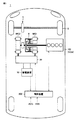
図1を参照して、ハイブリッド車両1は、エンジン100と、モータジェネレータMG1,MG2と、動力分割装置4と、減速機5と、駆動輪6とを備える。また、ハイブリッド車両1は、蓄電装置10と、PCU(Power Control Unit)20と、制御装置200とをさらに備える。
Referring to FIG. 1,
ハイブリッド車両1は、エンジン100およびモータジェネレータMG2の少なくとも一方から出力される駆動力によって走行可能である。エンジン100は、たとえば、ガソリンエンジンやディーゼルエンジン等の内燃機関により構成され、車両の駆動力を発生する。また、エンジン100は、発電機として作動可能なモータジェネレータMG1を駆動するための駆動力を発生する。
エンジン100は、モータジェネレータMG1によりクランキングされて始動し得る。このエンジン100は、吸気バルブの作動特性を変更するための可変動弁装置を有する。車両の走行状況やエンジン100の始動性に応じて、制御装置200により可変動弁装置が制御される。エンジン100の排気通路には、触媒を用いてエンジン100の排気を浄化する排気浄化装置が設けられている。エンジン100、可変動弁装置、および排気浄化装置については、後ほど詳しく説明する。
動力分割装置4は、エンジン100が発生する駆動力を、減速機5を介して駆動輪6を駆動するための駆動力と、モータジェネレータMG1を駆動するための駆動力とに分割可能に構成される。動力分割装置4は、たとえば遊星歯車によって構成される。
Power split
モータジェネレータMG1,MG2は、交流回転電機であり、たとえば、三相交流同期電動発電機である。モータジェネレータMG1は、動力分割装置4を介して受けるエンジン100の駆動力を用いて発電し得る。たとえば、蓄電装置10のSOCが所定の下限に達すると、エンジン100が始動してモータジェネレータMG1により発電が行なわれる。モータジェネレータMG1によって発電された電力は、PCU20により電圧変換され、蓄電装置10に一時的に蓄えられたり、モータジェネレータMG2に直接供給されたりする。
Motor generators MG1 and MG2 are AC rotating electric machines, for example, three-phase AC synchronous motor generators. Motor generator MG <b> 1 can generate electric power using the driving force of
モータジェネレータMG2は、蓄電装置10に蓄えられた電力、およびモータジェネレータMG1によって発電された電力の少なくとも一方を用いて駆動力を発生する。モータジェネレータMG2の駆動力は、減速機5を介して駆動輪6に伝達される。なお、図1では、駆動輪6は前輪として示されているが、前輪に代えて、または前輪とともに、モータジェネレータMG2によって後輪を駆動してもよい。
Motor generator MG2 generates a driving force using at least one of the electric power stored in
なお、車両の制動時には、減速機5を介して駆動輪6によりモータジェネレータMG2が駆動され、モータジェネレータMG2が発電機として作動する。これにより、モータジェネレータMG2は、制動エネルギーを電力に変換する回生ブレーキとして作動する。モータジェネレータMG2により発電された電力は、蓄電装置10に蓄えられる。
During braking of the vehicle, motor generator MG2 is driven by
PCU20は、モータジェネレータMG1,MG2を駆動するための駆動装置である。PCU20は、モータジェネレータMG1,MG2を駆動するためのインバータを含み、さらに、インバータと蓄電装置10との間で電圧変換するためのコンバータを含んでもよい。
蓄電装置10は、再充電可能な直流電源であり、たとえば、ニッケル水素やリチウムイオン等の二次電池を含んで構成される。蓄電装置10の電圧は、たとえば200V程度である。蓄電装置10は、モータジェネレータMG1,MG2によって発電された電力を蓄える。なお、蓄電装置10として、大容量のキャパシタも採用可能であり、蓄電装置10は、モータジェネレータMG1,MG2による発電電力を一時的に蓄え、その蓄えた電力をモータジェネレータMG2へ供給可能な電力バッファであれば如何なるものでもよい。また、蓄電装置10には、蓄電装置10の温度、電圧および電流を検出するためのセンサが設けられ、センサによる検出値が制御装置200へ出力される。
The
制御装置200は、CPU(Central Processing Unit)や、記憶装置、入出力バッ
ファ等(いずれも図示せず)を含むECU(Electronic Control Unit)を含んで構成
される。制御装置200は、各種センサからの信号(アクセル開度ACCや車速VSS等)の入力や各機器への制御信号の出力を行なうとともに、ハイブリッド車両1における各機器の制御を行なう。主要なものとして、制御装置200は、ハイブリッド車両1の走行制御や、排気浄化装置の触媒の暖機を行なうための触媒暖機制御、走行制御および触媒暖機制御に応じた可変動弁装置の制御等を実行する。制御装置200の動作については、後ほど説明する。
The
(エンジンの構成)
次に、可変動弁機構を有するエンジンの構成について説明する。
(Engine configuration)
Next, the configuration of an engine having a variable valve mechanism will be described.
図2は、図1に示されたエンジン100の構成を示す図である。
図2を参照して、エンジン100への吸入空気量は、スロットルモータ312により駆動されるスロットルバルブ104により調整される。インジェクタ108は、吸気ポートに燃料を噴射する。吸気ポートにおいて、燃料と空気とが混合される。混合気は、吸気バルブ118が開くことによって、シリンダ106内へ導入される。なお、インジェクタ108は、シリンダ106内に直接燃料を噴射する直噴インジェクタとして設けられてもよい。あるいは、インジェクタ108は、ポート噴射用と直噴用との両方が設けられてもよい。
FIG. 2 is a diagram showing a configuration of
Referring to FIG. 2, the intake air amount to
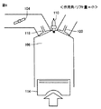
シリンダ106内の混合気は、点火プラグ110により着火されて燃焼する。燃焼後の混合気すなわち排気ガスは、排気通路に排出される。排気通路には、触媒を用いて排気ガスを浄化する排気浄化装置が設けられる。排気浄化装置は、触媒112S(以下「S/C(スタートキャット)触媒」とも称する。)と、S/C触媒112Sよりも下流側に配置される触媒112U(以下「U/F(アンダーフロア)触媒」とも称する。)とを含んで構成される。排気ガスは、S/C触媒112SおよびU/F触媒112Uにより浄化された後、車外に排出される。混合気の燃焼によりピストン114が押し下げられ、クランクシャフト116が回転する。
The air-fuel mixture in the
シリンダ106の頭頂部には、吸気バルブ118および排気バルブ120が設けられる。シリンダ106に導入される空気の量および時期は、吸気バルブ118により制御される。シリンダ106から排出される排気ガスの量および時期は、排気バルブ120により制御される。吸気バルブ118はカム122により駆動され、排気バルブ120はカム1
24により駆動される。
An
24.
吸気バルブ118は、後に詳細に説明するように、VVL(Variable Valve Lift)装置400によって、吸気バルブ118の作動特性が制御される。以下では、吸気バルブ118の作動特性として、リフト量および作用角が制御される例について説明する。なお、排気バルブ120についても、リフト量および/または作用角を制御するようにしてもよい。また、開閉タイミングを制御するVVT(Variable Valve Timing)装置をVVL装置400に組み合わせもよい。
As will be described in detail later, the operating characteristics of the
エンジン100は、EGR(Exhaust Gas Recirculation)装置をさらに含む。EGR装置は、EGR通路140およびEGRバルブ142を含む。EGR通路140は、エンジン100Aの排気を吸気側へ還流するための管路である。EGRバルブ142は、EGR通路140に設けられ、制御装置200によって開閉が制御される。
EGRバルブ142が開かれると、EGR通路140によって排気路と吸気路とが連通され、EGRバルブ142が閉じられると、EGR通路140は遮断される。EGRバルブ142を開いて排気を吸気路に還流することによって、スロットル損失を低減させ、ポンピングロスを低減することができる。すなわち、EGR装置によって燃費を向上させることができる。
When the
制御装置200には、アクセル開度ACCや車速VSSを示す信号のほか、カム角センサ300、クランク角センサ302、ノックセンサ304、スロットル開度センサ306、水温センサ309および、VVL位置センサ311の各センサから信号が入力される。
In addition to signals indicating the accelerator opening ACC and the vehicle speed VSS, the
カム角センサ300は、カムの位置を表す信号を出力する。クランク角センサ302は、クランクシャフト116の回転数(エンジン回転数)およびクランクシャフト116の回転角度を表す信号を出力する。ノックセンサ304は、エンジン100の振動の強度を表す信号を出力する。スロットル開度センサ306は、スロットル開度θthを表す信号を出力する。水温センサ309は、エンジン100の冷却水温度Twを表す信号を出力する。
The
VVL位置センサ311は、VVL装置400によって制御される吸気バルブ118の現時点の作動特性を示すデータを検出するように構成される。VVL位置センサ311による検出値Lvは、制御装置200へ入力される。すなわち、制御装置200は、VVL位置センサ311の検出値Lvに基づいて、リフト量および作用角の現在の値を検知することができる。
The
さらに、制御装置200は、これらの各センサからの信号に基づいてエンジン100を制御する。具体的には、制御装置200は、車両の走行状況や排気浄化装置の暖機状況に応じてエンジン100が所望の運転ポイントで運転されるように、スロットル開度θth、点火時期、燃料噴射時期、燃料噴射量、EGR装置の動作(EGRバルブ142の開度)、吸気バルブの作動状態(開閉タイミング、リフト量、作用角等)を制御する。なお、運転ポイントとは、エンジン100のパワー、トルクおよび回転数が決定されるエンジン100の動作点であり、エンジン100が所望のパワーやトルクを出力するようにエンジン100の運転ポイントが決定される。
Further,
なお、本実施の形態では、エンジン出力がパワーベースで制御される例を説明する。したがって、制御装置200は、ハイブリッド車両1の走行制御において、エンジン100への要求出力としてエンジン要求パワーを設定する。さらに、制御装置200は、エンジン100がエンジン要求パワーに従って出力を発生するための動作点(エンジン回転数およびエンジントルクの組み合わせ)で動作するように、上記のパラメータ群を制御する。
In the present embodiment, an example in which engine output is controlled on a power basis will be described. Therefore,
図3は、VVL装置400において実現されるバルブ変位量とクランク角の関係を示す図である。図3を参照して、排気行程において排気バルブ120が開いて閉じ、吸気行程において吸気バルブ118が開いて閉じる。排気バルブ120のバルブ変位量が波形EXに示されており、これに対して吸気バルブ118のバルブ変位量が波形IN1,IN2に示されている。
FIG. 3 is a diagram showing the relationship between the valve displacement amount and the crank angle realized in the
なお、バルブ変位量とは、吸気バルブ118が閉じた状態からの吸気バルブ118の変位量である。リフト量とは、吸気バルブ118の開度がピークに達したときのバルブ変位量である。作用角とは、吸気バルブ118が開いてから閉じるまでのクランク角度である。
The valve displacement is the displacement of the
吸気バルブ118の作動特性は、VVL装置400によって波形IN1,IN2の間で変化する。波形IN1は、リフト量および作用角が最小の場合を示す。波形IN2は、リフト量および作用角が最大の場合を示す。VVL装置400においては、リフト量が増大するにつれて、作用角も増大する。すなわち、本実施の形態で例示されるVVL装置400では、吸気バルブ118の作動特性として、リフト量および作用角が変更される。
The operating characteristic of the
図4は、吸気バルブ118のリフト量と作用角とを制御する装置の一例であるVVL装置400の正面図である。
FIG. 4 is a front view of a
図4を参照して、VVL装置400は、一方向に延びる駆動軸410と、駆動軸410の外周面を覆う支持パイプ420と、支持パイプ420の外周面上で駆動軸410の軸方向に並んで配置された入力アーム430および揺動カム440とを備える。駆動軸410の先端には、駆動軸410を直線運動させるアクチュエータ(図示せず)が接続される。
Referring to FIG. 4,
VVL装置400には、各気筒に設けられた1つのカム122に対応して、1つの入力アーム430が設けられる。入力アーム430の両側には、各気筒に設けられた一対の吸気バルブ118のそれぞれに対応して、2つの揺動カム440が設けられる。
The
支持パイプ420は、中空円筒状に形成されており、カムシャフト130に対して平行に配置される。支持パイプ420は、軸方向へ移動したり、回転したりしないようにシリンダヘッドに固定される。
The
支持パイプ420の内部には、その軸方向に摺動可能なように駆動軸410が挿入される。支持パイプ420の外周面上には、駆動軸410の軸芯を中心として揺動可能で、かつ、その軸方向には移動しないように、入力アーム430および2つの揺動カム440が設けられる。
A
入力アーム430は、支持パイプ420の外周面から離れる方向に突出するアーム部432と、アーム部432の先端に回転可能に接続されたローラ部434とを有する。入力アーム430は、ローラ部434がカム122に当接可能な位置に配置されるように設けられる。
The
揺動カム440は、支持パイプ420の外周面から離れる方向に突出する略三角形状のノーズ部442を有する。ノーズ部442の一辺には、凹状に湾曲したカム面444が形成される。吸気バルブ118に設けられたバルブスプリングの付勢力により、ロッカアーム128に回転可能に取り付けられたローラがカム面444に押し付けられる。
The
入力アーム430および揺動カム440は、一体となって駆動軸410の軸芯を中心として揺動する。このため、カムシャフト130が回転すると、カム122に当接された入力アーム430が揺動し、この入力アーム430の動きに連動して揺動カム440も揺動する。この揺動カム440の動きが、ロッカアーム128を経由して吸気バルブ118に伝わり、吸気バルブ118が開閉される。
The
VVL装置400は、さらに、支持パイプ420の軸芯周りにおいて、入力アーム430と揺動カム440との相対位相差を変更する装置を備える。相対位相差を変更する装置によって、吸気バルブ118のリフト量および作用角が適宜変更される。
The
つまり、両者の相対位相差を拡大すれば、入力アーム430および揺動カム440の揺動角に対するロッカアーム128の揺動角が拡大され、吸気バルブ118のリフト量および作用角が増大される。
That is, if the relative phase difference between the two is increased, the swing angle of the
また、両者の相対位相差を縮小すれば、入力アーム430および揺動カム440の揺動角に対するロッカアーム128の揺動角が縮小され、吸気バルブ118のリフト量および作用角が小さくされる。
If the relative phase difference between the two is reduced, the swing angle of the
図5は、VVL装置400を部分的に示した斜視図である。図5中では、内部構造が明確に把握できるように一部が破断されて表わされる。
FIG. 5 is a perspective view partially showing the
図5を参照して、入力アーム430および2つの揺動カム440と、支持パイプ420の外周面との間に規定された空間には、支持パイプ420に対して、回転可能で、かつ軸方向に摺動可能に支持されたスライダギヤ450が収容される。スライダギヤ450は、支持パイプ420上を軸方向に摺動可能に設けられる。
Referring to FIG. 5, a space defined between
スライダギヤ450には、その軸方向の中央部に位置して、右ねじ螺旋状のヘリカルスプラインが形成されたヘリカルギヤ452が設けられる。また、スライダギヤ450には、ヘリカルギヤ452の両側に位置し、ヘリカルギヤ452とは逆に左ねじ螺旋状のヘリカルスプラインが形成されたヘリカルギヤ454が各々に設けられる。
The
一方、スライダギヤ450を収容する空間を規定する入力アーム430および2つの揺動カム440の内周面には、ヘリカルギヤ452および454に対応したヘリカルスプラインがそれぞれ形成される。つまり、入力アーム430には、右ねじ螺旋状のヘリカルスプラインが形成されており、そのヘリカルスプラインがヘリカルギヤ452に噛み合っている。また、揺動カム440には、左ねじ螺旋状のヘリカルスプラインが形成されており、そのヘリカルスプラインがヘリカルギヤ454に噛み合っている。
On the other hand, helical splines corresponding to the
スライダギヤ450には、一方のヘリカルギヤ454とヘリカルギヤ452との間に位置して、周方向に延びる長穴456が形成される。また、図示しないが、支持パイプ420には、長穴456の一部と重なるように、軸方向に延びる長穴が形成される。支持パイプ420の内部に挿通された駆動軸410には、これら長穴456および図示しない長穴の重なった部分を通じて突出する係止ピン412が一体に設けられる。
The
駆動軸410に連結されるアクチュエータ(図示せず)によって、駆動軸410がその軸方向に移動すると、スライダギヤ450が係止ピン412により押され、ヘリカルギヤ452および454が同時に駆動軸410の軸方向に移動する。このようなヘリカルギヤ452および454の移動に対して、これらにスプライン係合された入力アーム430および揺動カム440は、軸方向に移動しない。そのため、入力アーム430と揺動カム440は、ヘリカルスプラインの噛み合いを通じて駆動軸410の軸芯周りに回動する。
When the
このとき、入力アーム430と揺動カム440とでは、形成されたヘリカルスプラインの向きが逆である。そのため、入力アーム430と揺動カム440の回動方向は互いに逆方向となる。これにより、入力アーム430と揺動カム440との相対位相差が変化し、既に説明したように吸気バルブ118のリフト量および作用角が変更される。
At this time, the
たとえば、図2に示したVVL位置センサ311は、入力アーム430および揺動カム440の間の機械的な位相差を検出可能な機構を有するように構成される。あるいは、図示しないアクチュエータによって移動される駆動軸410の軸方向の位置を検出可能な機構を有するように、VVL位置センサ311を構成することも可能である。なお、VVL位置センサ311は、その検出値から直接あるいは間接的に吸気バルブ118の作動特性であるリフト量および作用角を求めることが可能であれば、任意の構成とすることができる。
For example, the
制御装置200は、駆動軸410を直線運動させるアクチュエータの操作量を調整することによって吸気バルブ118のリフト量および作用角を制御する。このアクチュエータは、たとえば、電動モータによって構成することができる。この場合には、アクチュエータを構成する電動モータは、蓄電装置10とは別個のバッテリ(補機バッテリ)から電力供給を受けることが一般的である。あるいは、上記アクチュエータは、エンジン100によって駆動されるオイルポンプから発生する油圧によって作動するように構成することも可能である。
The
なお、VVL装置は、図4および図5に例示した形式のものに限られない。たとえば、電気的にあるいは油圧を用いてバルブを駆動するVVL装置などを用いてもよい。すなわち、本実施の形態において、吸気バルブ118の作動特性(リフト量および作用角)を変更するための機構は特に限定されるものではなく、公知の機構を適宜適用することができる。
Note that the VVL device is not limited to the type illustrated in FIGS. 4 and 5. For example, a VVL device that drives a valve electrically or using hydraulic pressure may be used. That is, in the present embodiment, the mechanism for changing the operating characteristics (lift amount and operating angle) of
図6は、吸気バルブ118の作動特性を3段階に切替可能なVVL装置400において実現されるバルブ変位量とクランク角の関係を示す図である。
FIG. 6 is a diagram showing the relationship between the valve displacement amount and the crank angle realized in the
図6を参照して、VVL装置400は、吸気バルブ118の作動特性を第1から第3の特性のいずれかに切替可能である。第1の特性は、波形IN1aで示される。第2の特性は、波形IN2aで示され、作動特性が第1の特性であるときよりもリフト量および作用角が大きい。第3の特性は、波形IN3aで示され、作動特性が第2の特性であるときよりもリフト量および作用角がさらに大きい。
Referring to FIG. 6,
なお、以下では、3つの作動特性のうちリフト量および作用角が相対的に小さい第1の特性(波形IN1a)を「小カム特性」とも称し、3つの作動特性のうちリフト量および作用角が相対的に大きい第3の特性(波形IN3a)を「大カム特性」とも称する。また、リフト量および作用角が小カム特性のときよりも大きく、かつ、大カム特性のときよりも小さい第2の特性(波形IN2a)を「中カム特性」とも称する。 Hereinafter, the first characteristic (waveform IN1a) having a relatively small lift amount and working angle among the three operating characteristics is also referred to as a “small cam characteristic”, and the lift amount and working angle of the three operating characteristics are The relatively large third characteristic (waveform IN3a) is also referred to as a “large cam characteristic”. Further, the second characteristic (waveform IN2a) in which the lift amount and the operating angle are larger than those in the small cam characteristic and smaller than in the large cam characteristic is also referred to as “medium cam characteristic”.
図7は、吸気バルブ118の作動特性が大カム特性であるときのピストン上昇時の動作を説明する図である。
FIG. 7 is a diagram for explaining the operation when the piston is raised when the operation characteristic of the
図7を参照して、吸気バルブ118の作動特性が大カム特性である場合には、ピストン114の上昇時に吸気バルブ118の閉じるタイミングが遅くなる。これにより、エンジン100は、アトキンソンサイクルで運転され、燃費の向上が図られる。一方で、吸気行程にてシリンダ106内に吸入された空気の一部がシリンダ106外へ戻されるため、シリンダ106内における混合気の圧縮比が低減するので混合気の着火性は悪化する。これにより、混合気の燃焼状態は悪化傾向となり、排気ガス中のエミッションは悪化する。なお、圧縮行程における圧縮反力が低減するので、エンジン始動時に適用すると、エンジン始動に伴う振動を低減することができる。
Referring to FIG. 7, when the operation characteristic of
図8は、吸気バルブ118の作動特性が小カム特性であるときのピストン上昇時の動作を説明する図である。また、図9は、吸気バルブ118の作動特性が小カム特性であるときのピストン下降時の動作を説明する図である。
FIG. 8 is a diagram for explaining the operation when the piston is raised when the operation characteristic of the
図8および図9を参照して、吸気バルブ118の作動特性が小カム特性である場合には、ピストン114の下降時に吸気バルブ118の開くタイミングが遅くなるので、シリンダ106内に負圧が発生した状態で吸気ポートから混合気が吸気されることとなり、シリンダ106内の燃料の混合が促進される。さらに、ピストン114の上昇時に吸気バルブ118の閉じるタイミングは早くなるので、シリンダ106内における混合気の圧縮比が上昇し、混合気の着火性が向上する。これらによって、混合気の燃焼状態は良好となり、排気ガス中のエミッションが改善される。一方、ポンピングロスが大きくなるので、燃費は相対的に悪化する。
Referring to FIGS. 8 and 9, when the operation characteristic of
なお、エンジン始動時に小カム特性を適用すると、大カム特性の場合と比較して、振動は大きくなるが、着火性が高いためエンジン冷間時の始動性を高めることができる。一方で、エンジン始動時に大カム特性を適用すると、小カム特性の場合と比較して、エンジン始動時の振動を抑制できる一方で、エンジン冷間時には始動性の低下が懸念される。 When the small cam characteristic is applied at the time of starting the engine, the vibration is increased as compared with the case of the large cam characteristic. However, since the ignitability is high, the startability when the engine is cold can be improved. On the other hand, when the large cam characteristic is applied at the time of starting the engine, the vibration at the time of starting the engine can be suppressed as compared with the case of the small cam characteristic.
図10には、吸気バルブ118の作動特性(リフト量および作用角)を変更したときのエンジン出力特性を説明するための概念図が示される。
FIG. 10 is a conceptual diagram for explaining the engine output characteristics when the operating characteristics (lift amount and operating angle) of the
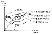
図10を参照して、横軸にはエンジン回転数が示され、縦軸にはエンジントルクが示される。一点鎖線で示されるラインは、第1〜第3の特性(IN1a〜IN3a)に対応するトルク特性を示す。実線で示される円は等燃費ラインを示し、円の中心に近づくほど燃費が向上する。 Referring to FIG. 10, the horizontal axis represents the engine speed, and the vertical axis represents the engine torque. A line indicated by an alternate long and short dash line indicates torque characteristics corresponding to the first to third characteristics (IN1a to IN3a). A circle indicated by a solid line indicates an equal fuel consumption line.
概略的には、エンジン100の低回転域では、リフト量および作用角が小さいほど、大きなエンジントルクを出力することができる。一方で、エンジン100の高回転域では、リフト量および作用角が大きいほど、大きなエンジントルクを出力することができる。また、中回転域で中カム特性を適用したときに、エンジン100の燃費が最良となる。触媒暖機制御の完了後における通常制御では、エンジン100は、基本的には、上記特性に照らして予め定められたエンジン動作線上で運転される。このエンジン動作線は、図10中に実線で表記される。
Schematically, in the low rotation range of the
エンジン動作線に従えば、領域R1で示される低回転域では、エンジンの振動を抑制することが重要となる。この低回転域では、EGRバルブ142(図2)の閉によってEGRガスの導入が停止され、アトキンソンサイクルによる燃費の向上が図られる。このため、領域R1では、リフト量および作用角が大きくなるように吸気バルブ118の作動特性として第3の特性(IN3a:大カム特性)が選択される。
According to the engine operating line, it is important to suppress the vibration of the engine in the low rotation range indicated by the region R1. In this low rotation range, the introduction of EGR gas is stopped by closing the EGR valve 142 (FIG. 2), and fuel efficiency is improved by the Atkinson cycle. For this reason, in the region R1, the third characteristic (IN3a: large cam characteristic) is selected as the operation characteristic of the
領域R2で示される中回転域では、EGRバルブ142(図2)の開によるEGRガスの導入量の増加によって、燃費の向上が図られる。よって、領域R2では、リフト量および作用角が中間となるように吸気バルブ118の作動特性として第2の特性(中カム特性)が選択される。
In the middle rotation range indicated by the region R2, fuel efficiency is improved by increasing the amount of EGR gas introduced by opening the EGR valve 142 (FIG. 2). Therefore, in the region R2, the second characteristic (medium cam characteristic) is selected as the operation characteristic of the
すなわち、吸気バルブ118のリフト量および作用角が大きい場合(大カム特性)は、EGRガスの導入による燃費向上よりもアトキンソンサイクルによる燃費向上が優先される。一方、中間のリフト量および作用角が選択された場合(中カム特性)は、アトキンソンサイクルによる燃費向上よりもEGRガスの導入による燃費向上が優先される。
That is, when the lift amount and the operating angle of the
領域R3で示される高回転域では、吸気慣性によって多量の空気をシリンダ内へ導入し、実圧縮比の上昇による出力性能の向上が図られる。よって、領域R3では、リフト量および作用角が大きくなるように吸気バルブ118の作動特性として第3の特性(大カム)が選択される。このように、走行中の通常制御では、エンジン100の運転状態(動作点)に応じてリフト量および作用角が決定される。
In the high rotation range indicated by the region R3, a large amount of air is introduced into the cylinder by the intake inertia, and the output performance is improved by increasing the actual compression ratio. Therefore, in the region R3, the third characteristic (large cam) is selected as the operation characteristic of the
(触媒暖機制御)
再び図1および図2を参照して、このハイブリッド車両1は、エンジン100を停止してモータジェネレータMGによる走行(EV走行)が可能である。すなわち、ハイブリッド車両1では、エンジン100は間欠運転される。たとえば、エンジン停止状態で所定のエンジン始動条件が成立すると、エンジン始動処理が実行される。代表的には、エンジン始動条件は、ハイブリッド車両1に要求される出力が所定のしきい値を超えたときに成立する。反対に、エンジン100の作動時に、ハイブリッド車両1に要求される出力が低下すると、エンジン停止条件が成立して、エンジン停止処理が実行される。
(Catalyst warm-up control)
Referring to FIGS. 1 and 2 again, this
エンジン始動条件は、排気通路に設けられるS/C触媒112S(図2)の暖機を要求する所定の触媒暖機実施条件が成立した場合にも成立する。制御装置200は、触媒暖機実施条件の成立時には、エンジン100を通常制御とは異なる状態で動作させる触媒暖機制御を実行する。触媒暖機実施条件は、たとえば、S/C触媒112Sの温度(以下、触媒温度)に基づいて実行される。触媒温度は、後述するように、エンジン100の動作に基づいて推定することが可能である。
The engine start condition is also satisfied when a predetermined catalyst warm-up execution condition that requires warm-up of the S / C catalyst 112S (FIG. 2) provided in the exhaust passage is satisfied. When the catalyst warm-up execution condition is satisfied,
触媒温度はエンジン停止時に低下するため、触媒暖機実施条件は、エンジン停止状態中に成立する。ただし、触媒暖機実施条件の成立時において、エンジン100は冷間状態であるとは限らず、エンジン100が温間状態のときに触媒暖機実施条件が成立するケースも存在する。これは、S/C触媒112Sと、エンジン100の本体部分との配置個所および熱容量が異なることに起因する。通常、S/C触媒112Sは、外気に晒される状況で配置され、かつ、熱容量も比較的小さいため、エンジン停止中における触媒温度の低下は、エンジン100の冷却水温度Twの低下よりも大きい。この結果、外気条件等によっては、エンジン100の冷却水温度Twがそれ程低下していないのに、触媒温度の低下によって触媒暖機実施条件が成立することがある。
Since the catalyst temperature decreases when the engine is stopped, the catalyst warm-up execution condition is satisfied while the engine is stopped. However, when the catalyst warm-up execution condition is satisfied, the
図11には、触媒暖機制御におけるエンジン制御を説明するための動作波形図が示される。 FIG. 11 is an operation waveform diagram for explaining engine control in catalyst warm-up control.
図11を参照して、横軸は時間を示し、縦軸の上から順に、エンジン回転数Ne、エンジンパワーPe、エンジン100の点火時期aop、S/C触媒112Sの排気上流側端部(たとえば端面10mm位置)の浄化率、S/C触媒112Sの中央での浄化率、エンジン100の燃焼温度、吸気バルブ118の作動特性の設定状態を示す波形が示されている。
Referring to FIG. 11, the horizontal axis indicates time, and engine speed Ne, engine power Pe, ignition timing aop of
なお、浄化率は、入力される排気ガスのエミッション濃度(代表的にはHC濃度)に対する、出力される排気ガスのエミッション濃度の比で定義され、実際には、予め準備されたマップや関係式等を用いて、触媒温度に基づいて推定される。触媒温度は、予め準備されたマップや関係式等を用いて、エンジン100の吸入空気量と点火遅角量とから推定される。
The purification rate is defined by the ratio of the emission concentration of the exhaust gas to be output with respect to the emission concentration (typically, the HC concentration) of the input exhaust gas. Is estimated based on the catalyst temperature. The catalyst temperature is estimated from the intake air amount of the
なお、触媒浄化率(端面10mm)は、S/C触媒112Sの排気上流側端部の浄化率であって、一例としての排気上流側端面10mmでの浄化率を示し、以下では「端面浄化率」とも称する。また、触媒浄化率(中央)は、S/C触媒112S全体での浄化率を示し、以下では「中央浄化率」とも称する。
The catalyst purification rate (end
時刻t1において、S/C触媒112Sの暖機実施条件が成立すると、S/C触媒112Sの暖機のためにエンジン100が始動されるとともに、触媒暖機制御が開始される。
When the S / C catalyst 112S warm-up execution condition is satisfied at time t1, the
制御装置200は、S/C触媒112Sの排気上流側を先行して暖機するための第1暖機制御と、第2暖機制御との2段階に分けて触媒暖機制御を実行する。第1暖機制御は、エンジン100の始動直後に実行される。すなわち、時刻t1からは、第1暖機制御が実行される。
The
第1暖機制御では、制御装置200は、エンジン回転数Neをアイドリング回転数相当の一定値とした上で、エンジン出力(エンジンパワーPe)が第1運転パワーP1(たとえば0〜3kW程度の低パワー)となるように、エンジン100を運転する。なお、第1運転パワーP1は、走行パワーに応答するものではなく、ハイブリッド車両1の走行パワーは、モータジェネレータMG2から出力される。
In the first warm-up control, the
さらに、制御装置200は、第1暖機制御では、燃焼ガス(排気ガス)の温度を高めために、エンジン100の点火時期aopを遅角側に制御する。エンジン100のパワーを抑えて排気ガス量を抑えつつ、点火時期を遅角側にすることにより排気ガスの温度を高めてS/C触媒112Sを早期に暖機するためである。
Further, in the first warm-up control,
第1暖機制御により、触媒温度が上昇することに応じて、S/C触媒112Sの端面浄化率および中央浄化率が上昇する。第1暖機制御は、S/C触媒112Sの端面浄化率が100%に達するまで継続される。 With the first warm-up control, the end face purification rate and the central purification rate of the S / C catalyst 112S increase as the catalyst temperature increases. The first warm-up control is continued until the end face purification rate of the S / C catalyst 112S reaches 100%.
制御装置200は、第1暖機制御によってS/C触媒112Sの排気上流側が暖機されることにより、最低限の排気浄化能力が確保されると、第2暖機制御を実行する。したがって、時刻t2において、S/C触媒112Sの端面浄化率が100%に達すると、第1暖機制御が終了するともに、第2暖機制御が開始される。
When the exhaust gas upstream side of the S / C catalyst 112S is warmed up by the first warm-up control, the
第2暖機制御では、制御装置200は、遅角側に制御されていたエンジン100の点火時期aopを通常状態に復帰させるとともに、エンジン出力が、第1暖機制御時よりも大きくなるようにエンジン100を運転する。たとえば、第2暖機制御では、エンジンパワーPeが、第1暖機制御での第1運転パワーP1よりも大きい第2運転パワーP2(Pe=P2)とされる。この第2運転パワーP2は、走行パワーに応答するものではなく、S/C触媒112Sの排気浄化能力を超えないように設定される。第2暖機制御中においても、ハイブリッド車両1の走行パワーは、モータジェネレータMG2から出力される。走行パワーにかかわらずエンジンパワーPeが安定的に制御されることにより、エンジン100の運転が安定した状態でS/C触媒112Sの暖機が継続される。
In the second warm-up control, the
そして、時刻t3において、S/C触媒112Sの排気浄化能力が100%に達すると、第2暖機制御が終了される。これに伴い、触媒暖機制御も終了されて、エンジン100に対しては、走行パワーに基づく出力を発生するようにエンジン100を運転する通常制御が適用される。通常制御では、走行パワーに基づいてモータジェネレータMG2およびエンジン100を駆動する走行(HV走行)が行なわれるとともに、エンジン100への要求パワーが設定されて、エンジンパワーPeが当該エンジン要求パワーに従って制御されるように、エンジン出力が制御される。たとえば、図10に示したエンジン動作線に従って、吸気バルブ118の作動特性を含むエンジン100の運転が制御される。
When the exhaust purification capacity of the S / C catalyst 112S reaches 100% at time t3, the second warm-up control is terminated. Accordingly, the catalyst warm-up control is also terminated, and normal control for operating the
次に、触媒暖機制御における吸気バルブ118の作動特性について説明する。上述のように、触媒暖機制御の開始時において、エンジン100は冷間状態および温間状態のいずれともなり得る。なお、一般的には、エンジン100が冷間状態および温間状態のいずれであるかは、冷却水温度Tw(図2)に基づいて判別される。
Next, the operation characteristic of the
図11中には、エンジン冷間状態での触媒暖機制御における吸気バルブ118の制御が実線で表記される一方で、エンジン温間状態での触媒暖機制御における吸気バルブ118の制御が点線で表記される。
In FIG. 11, the control of the
エンジン冷間状態では、エンジン始動直後の第1暖機制御中には、点火時期aopが遅角側に制御されることも加わって、エンジン100の燃焼状態が不安定である。したがって、時刻t1〜t2では、図9で説明したように、混合気の燃焼状態を良好にすることを優先して、吸気バルブ118の作動特性が小カム特性(図6のIN1a)に設定される。これにより、第1暖機制御における排気ガス中のエミッションも抑制することができる。一方で、エンジン100での燃焼状態が安定すると、吸気バルブ118の作動特性を大カム特性(図6のIN3a)に設定することが好ましい。エンジン100をアトキンソンサイクルで運転することによって、燃費の向上を図るためである。
In the engine cold state, during the first warm-up control immediately after the engine is started, the ignition timing aop is controlled to the retard side, and the combustion state of the
したがって、エンジン冷間状態での触媒暖機制御には、吸気バルブ118の作動特性は第1暖機制御(時刻t1〜t2)では小カム特性(図6のIN1a)に設定され、第2暖機制御(時刻t2〜t3)では大カム特性(図6のIN3a)に設定される。なお、第2暖機制御において、吸気バルブ118の作動特性が中カム特性(図6のIN2a)に設定される期間を設けた後に、吸気バルブ118の作動特性を大カム特性(図6のIN3a)へ変化させてもよい。
Therefore, in the catalyst warm-up control in the engine cold state, the operating characteristic of the
一方で、エンジン温間状態では、点火時期aopが遅角側に制御されても、エンジン100の燃焼状態は比較的良好である。したがって、第1暖機制御では、図7で説明したように、エンジン始動による振動を抑制することを優先して、吸気バルブ118の作動特性が大カム特性(IN3a)に設定される。
On the other hand, in the engine warm state, even when the ignition timing aop is controlled to the retard side, the combustion state of the
一方で、吸気バルブ118の作動特性が大カム特性(IN3a)のときには、図7で説明したように、排気ガス中のエミッションは悪化する。したがって、触媒暖機制御中を通じて、吸気バルブ118の作動特性を大カム特性(IN3a)に維持することは好ましくないため、第2暖機制御(時刻t2〜t3)では、エミッションが抑制される方向に吸気バルブ118の作動特性を変更することが好ましい。
On the other hand, when the operation characteristic of the
この結果、エンジン温間状態での触媒暖機制御には、吸気バルブ118の作動特性は第1暖機制御(時刻t1〜t2)では大カム特性(図6のIN3a)に設定され、第2暖機制御(時刻t2〜t3)では小カム特性(図6のIN1a)に設定される。なお、第2暖機制御において、吸気バルブ118の作動特性が中カム特性(図6のIN2a)に設定される期間を設けた後に、吸気バルブ118の作動特性を小カム特性(図6のIN1a)へ変化させることも可能である。
As a result, in the catalyst warm-up control in the engine warm state, the operating characteristic of the
第2暖機制御におけるエンジン出力(エンジンパワーPe)は、上述のように、走行パワーに応答するものではなく、S/C触媒112Sの排気浄化能力を超えない値に設定される。しかしながら、第2運転パワーP2が吸気バルブ118の作動特性と調和していないと、第2暖機制御中にエンジン100のエミッションまたは燃費が悪化することが懸念される。
The engine output (engine power Pe) in the second warm-up control does not respond to the traveling power as described above, and is set to a value that does not exceed the exhaust purification capacity of the S / C catalyst 112S. However, if the second operating power P2 is not in harmony with the operating characteristics of the
再び、図10を参照して、触媒暖機制御中におけるエンジン回転数は、アイドル回転数相当であり、領域R1に相当する。したがって、触媒暖機制御中の回転数域(低回転数域)では、リフト量および作用角を小さくした方がエンジン出力を高めることができる。したがって、リフト量および作用角が小さい領域では、第2運転パワーP2を大きく設定する方が、エンジン100の燃費を高めることができる。逆に言うと、吸気バルブ118の作動特性が小カム特性であるときに、第2運転パワーP2が低過ぎると、燃費の悪化が懸念される。
Referring to FIG. 10 again, the engine speed during the catalyst warm-up control is equivalent to the idle speed, and corresponds to region R1. Therefore, in the engine speed range (low engine speed range) during catalyst warm-up control, the engine output can be increased by reducing the lift amount and the operating angle. Therefore, in a region where the lift amount and the operating angle are small, the fuel consumption of
一方で、図12には、吸気バルブ118の作動特性に応じた排出ガス量および積算HC排出量およびの間の特性関係が示される。
On the other hand, FIG. 12 shows a characteristic relationship between the exhaust gas amount and the integrated HC exhaust amount according to the operation characteristic of the
図12を参照して、横軸に示されるエンジン100からの排出ガス量は、エンジンパワーPeに比例する。また、縦軸には積算HC排出量が示される。吸気バルブ118が小カム特性(IN1a)であるときの排出ガス量および積算HC排出量の間の関係は特性線510で示される。同様に、吸気バルブ118が大カム特性(IN3a)であるときの排出ガス量および積算HC排出量の間の関係は特性線520で示される。
Referring to FIG. 12, the amount of exhaust gas from
特性線510および520から理解されるように、積算HC排出量は排出ガス量に比例する。そして、吸気バルブ118のリフト量および作用角が大きいほど、比例係数は大きくなる。
As understood from the
したがって、第2暖機制御中における積算HC排出量を、吸気バルブ118の作動特性が大カム特性(IN3a)のとき、および、小カム特性(IN1a)の間で同等とするためには、大カム特性(IN3a)のときの排出ガス量(G1)は、小カム特性(IN1a)のときの排出ガス量(G2)よりも小さくする必要がある。
Therefore, in order to make the accumulated HC discharge amount during the second warm-up control equal when the operation characteristic of the
逆に言うと、吸気バルブ118が大カム特性(IN3a)であるときに、エンジンパワーPe(第2運転パワーP2)が高過ぎると、第2暖機制御中における積算HC排出量が増大する。
Conversely, when the
したがって、本実施の形態に従うハイブリッド車両では、図13に示されるように、触媒暖機制御における第2暖機制御時のエンジン出力(第2運転パワーP2)を吸気バルブ118の作動特性と連動させて設定する。
Therefore, in the hybrid vehicle according to the present embodiment, as shown in FIG. 13, the engine output (second operating power P2) at the time of the second warm-up control in the catalyst warm-up control is linked with the operation characteristic of
図13を参照して、第2暖機制御における第2運転パワーP2および吸気バルブ118の作動特性(リフト量および作用角)の間の対応関係が設定される。たとえば、吸気バルブ118の作動特性を三段階に設定することが可能なVVL装置400では、小カム特性(IN1a)、中カム特性(IN2a)および大カム特性(IN3a)のそれぞれに対応させてエンジン出力(第2運転パワーP2)を対応付けるための特性点501〜503が定められる。
Referring to FIG. 13, a correspondence relationship between the second operating power P2 and the operating characteristics (lift amount and operating angle) of
たとえば、特性点501に従えば、吸気バルブ118の作動特性が小カム特性(IN1a)であるときにはP2=Pe1に設定される。一方で、特性点502に従えば、吸気バルブ118の作動特性が中カム特性(IN2a)であるときにはP2=Pe2に設定され、特性点503に従えば、吸気バルブ118の作動特性が大カム特性(IN3a)であるときにはP2=Pe3に設定される。
For example, according to the
Pe1〜Pe3の間には、Pe1>Pe2>Pe3の関係が成立する。すなわち、第2暖機制御時の吸気バルブ118のリフト量および作用角が大きいほど、エンジン出力(エンジンパワ−Pe)が小さくなるように、第2暖機制御中の第2運転パワーP2が設定される。
The relationship Pe1> Pe2> Pe3 is established between Pe1 and Pe3. That is, the second operating power P2 during the second warm-up control is set so that the engine output (engine power-Pe) decreases as the lift amount and the operating angle of the
なお、エンジン100では、吸気バルブ118の各作動特性での実機実験等によって、特性点501〜503を予め定めることができる。また、特性点501〜503を内挿および外挿することによって、吸気バルブ118のリフト量および作用角の連続的な変化に対してエンジン出力(第2運転パワーP2)を対応付けるための特性線500を求めることも可能である。
In
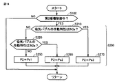
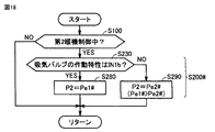
図14は、本発明の実施の形態1に従うハイブリッド車両における触媒暖機制御での第2暖機制御時のエンジン出力の設定を説明するフローチャートである。図14に示した制御処理は、触媒暖機制御の実行中に、制御装置200によって所定の制御周期毎に繰返し実行される。
FIG. 14 is a flowchart illustrating setting of the engine output during the second warm-up control in the catalyst warm-up control in the hybrid vehicle according to the first embodiment of the present invention. The control process shown in FIG. 14 is repeatedly executed at predetermined control cycles by the
図14を参照して、制御装置200は、ステップS100により、第2暖機制御中であるかどうかを判定する。図11の例では、ステップS100は、時刻t1〜t2の間YES判定とされる。
Referring to FIG. 14,
制御装置200は、第2暖機制御の実行中(S100のYES判定時)には、ステップS200により、吸気バルブの作動特性に応じて第2運転パワーP2を設定する。ステップS200は、以下のステップS210、S220およびS250〜S270を有する。
During execution of the second warm-up control (when YES is determined in S100),
制御装置200は、ステップS210およびS220により、吸気バルブ118の現在の作動特性が小カム特性(IN1a)、中カム特性(IN2a)および大カム特性(IN3a)のいずれであるかを峻別する。具体的には、ステップS210では、吸気バルブ118の作動特性が大カム特性(IN3a)であるかどうかが判定され、ステップS220では、吸気バルブ118の作動特性が中カム特性(IN2a)であるかどうかが判定される。ステップS210およびS220の判定は、VVL位置センサ311(図2)からの検出値Lvに基づいて実行することができる。
The
吸気バルブ118の作動特性が大カム特性(IN3a)であるときには(S210のYES判定時)、制御装置200は、ステップS270に処理を進める。また、制御装置200は、吸気バルブ118の作動特性が中カム特性(IN2a)であるときには(S210のNO判定時かつ、S220のYES判定時)、ステップS260に処理を進める。また、吸気バルブ118の作動特性が小カム特性(IN1a)であるとき(S210のNO判定時かつ、S220のNO判定時)には、制御装置200は、ステップS250に処理を進める。
When the operation characteristic of
制御装置200は、ステップS250では、図13中の特性点501に従って、P2=Pe1に設定する。同様に、制御装置200は、ステップS260では、図13中の特性点502に従ってP2=Pe2に設定する。また、制御装置200は、ステップS270では、図13中の特性点503に従って、P2=Pe3に設定する。
In step S250,
一方で、制御装置200は、第2暖機制御の非実行中(S100のNO判定値)には、S200の処理を非実行とする。
On the other hand, the
再び図11を参照して、第2暖機制御中(時刻t2〜t3)のエンジン出力(第2運転パワーP2)は、図13に示された特性関係に従って、吸気バルブ118の現在の作動特性と連動させて設定される。この結果、第2暖機制御中における吸気バルブ118の作動特性をエンジン100の状況に応じて適切化した下で、エンジン出力(第2運転パワーP2)を吸気バルブ118の作動特性と対応させて適切に設定することができる。この結果、第2暖機制御中において、エンジン出力および吸気バルブ118の作動特性が調和しないことによるエミッションおよび燃費の悪化を防止することができる。
Referring to FIG. 11 again, the engine output (second operating power P2) during the second warm-up control (time t2 to t3) is the current operating characteristic of
なお、図14に示した制御処理によれば、第2暖機制御中においてVVL装置400による吸気バルブ118の作動特性の変化が制限されている場合にも、エンジン出力(第2運転パワーP2)を適切に設定することができる。たとえば、異物の一時的な存在や極低温時の固着等によって、VVL装置400が吸気バルブの作動特性(リフト量および作用角)を変更する際の応答速度が低下したとき、あるいは、VVL装置400が故障したときに、吸気バルブ118の作動特性の変化は制限される。
Note that, according to the control process shown in FIG. 14, the engine output (second operating power P2) is also applied when the change in the operating characteristic of the
図15および図16は、吸気バルブの作動特性の変化が制限されたときの触媒暖機制御の動作波形図である。図15には、図11中に実線で示された吸気バルブ118の作動特性の制御において吸気バルブの作動特性が制限されたときの動作波形図が示される。
FIGS. 15 and 16 are operation waveform diagrams of the catalyst warm-up control when the change in the operation characteristic of the intake valve is restricted. FIG. 15 shows an operation waveform diagram when the operation characteristic of the intake valve is limited in the control of the operation characteristic of the
図15を参照して、図11で説明したように、エンジン冷間状態では、VVL装置400は、吸気バルブ118の作動特性を、第1暖機制御(時刻t1〜t2)では小カム特性(IN1a)に制御する一方で、第2暖機制御(時刻t2〜t3)では大カム特性(IN3a)に制御する。
Referring to FIG. 15, as described in FIG. 11, in the engine cold state, the
VVL装置400による制御が正常であるときには、図15中に点線で示したように、第2暖機制御が開始される時刻t2において、吸気バルブ118の作動特性は、大カム特性(IN3a)に制御される。これに応じて、第2暖機制御中におけるエンジン出力(第2運転パワーP2)は、特性点503に従うPe3へ向けて変化する。
When the control by the
一方、図15中には、VVL装置400による吸気バルブ118の作動特性の制御が制限されている場合の動作が実線で示される。たとえば、VVL装置400での固着等によって、時刻t2から遅れた時刻txにおいて、吸気バルブ118の作動特性が、小カム特性(IN1a)から大カム特性(IN3a)に変更されたものとする。
On the other hand, in FIG. 15, the operation when the control of the operation characteristic of the
この場合に、第2暖機制御中におけるエンジン出力(第2運転パワーP2)は、VVL位置センサ311の出力に基づいて、吸気バルブ118の作動特性の現在値に対応して設定される。したがって、時刻txまでの期間におけるP2は、Pe3ではなくPe1(Pe1>Pe3)に設定される。
In this case, the engine output (second operating power P2) during the second warm-up control is set corresponding to the current value of the operating characteristic of the
これにより、吸気バルブ118の実際の作動特性が小カム特性(IN1a)であるのに、制御上の目標である大カム特性(IN3a)に応じてP2=Pe3に設定されことにより、図10で説明した低回転域での燃費悪化を防止することができる。逆に言うと、時刻txまでのエンジン出力(第2運転パワーP2)を、実際の作動特性である小カム特性(IN1a)と対応させてP2=Pe1に設定することにより、燃費を改善することができる。
As a result, although the actual operating characteristic of the
一方で、図16には、図11中に点線で示された吸気バルブ118の作動特性の制御(エンジン温間状態)において吸気バルブの作動特性が制限されたときの動作波形図が示される。 On the other hand, FIG. 16 shows an operation waveform diagram when the operation characteristic of the intake valve is limited in the control of the operation characteristic of the intake valve 118 (engine warm state) indicated by the dotted line in FIG.
図16を参照して、図11で説明したように、たとえばエンジン温間状態では、VVL装置400は、吸気バルブ118の作動特性を、第1暖機制御(時刻t1〜t2)では大カム特性(IN3a)に制御する一方で、第2暖機制御(時刻t2〜t3)では小カム特性(IN1a)に制御する。
Referring to FIG. 16, as described with reference to FIG. 11, for example, in the engine warm state,
VVL装置400による制御が正常であるときには、図16中に点線で示したように、第2暖機制御が開始される時刻t2において、吸気バルブ118の作動特性は、小カム特性(IN3a)に制御される。これに応じて、第2暖機制御中におけるエンジン出力(第2運転パワーP2)は、特性点501に従うPe1へ向けて変化する。
When the control by the
一方、図16中には、VVL装置400による吸気バルブ118の作動特性の制御が制限されている場合の動作が実線で示される。たとえば、VVL装置400での一時的な異物の存在等によって、時刻t2から遅れた時刻txにおいて、吸気バルブ118の作動特性が、大カム特性(IN3a)から小カム特性(IN1a)に変更されたものとする。
On the other hand, in FIG. 16, the operation when the control of the operation characteristic of the
この場合に、第2暖機制御中におけるエンジン出力(第2運転パワーP2)は、吸気バルブ118の作動特性の現在値に基づいて、時刻txまでの期間において、Pe1ではなくPe3(Pe3<Pe1)に設定される。
In this case, the engine output (second operating power P2) during the second warm-up control is not Pe1 but Pe3 (Pe3 <Pe1) in the period up to time tx based on the current value of the operating characteristic of the
この際に、吸気バルブ118の実際の作動特性が大カム特性(IN3a)であるのに、エンジン出力(第2運転パワーP2)が、制御上の目標である小カム特性(IN1a)に応じてP2=Pe1に設定されると、図12で説明したように、積算HC排出量の増加によって、エミッションが悪化してしまう。
At this time, the actual operating characteristic of the
逆に言うと、時刻txまでのエンジン出力(第2運転パワーP2)を、実際の作動特性である大カム特性(IN3a)と対応させてP2=Pe3に設定することにより、エミッションの悪化を防止することができる。 In other words, the engine output (second operating power P2) up to time tx is set to P2 = Pe3 in correspondence with the actual cam characteristics (IN3a), thereby preventing emission deterioration. can do.
このように、本実施の形態1に従うハイブリッド車両による触媒暖機制御によれば、点火時期が遅角される第1暖機制御後における、点火時期が戻された第2暖機制御中におけるエンジン出力を、吸気バルブ118の作動特性と対応付けて適切に設定することができる。これにより、触媒暖機制御(特に、第2暖機制御中)において、エンジン出力および吸気バルブの作動特性が調和していないことによって、エミッションまたは燃費が悪化することを防止することができる。これにより、触媒暖機制御におけるエミッションおよび燃費を改善することができる。
Thus, according to the catalyst warm-up control by the hybrid vehicle according to the first embodiment, the engine in the second warm-up control in which the ignition timing is returned after the first warm-up control in which the ignition timing is retarded. The output can be appropriately set in association with the operation characteristic of the
また、図15および図16に示したように、吸気バルブ118の作動特性の現在の検出値と対応させて、第2暖機制御中における作動特性の変化に応じてエンジン出力(第2運転パワーP2)を変更することにより、VVL装置400による吸気バルブ118の作動特性の変化が制限されている場合にも、第2暖機制御中におけるエミッションまたは燃費の悪化を防止できる。
Further, as shown in FIGS. 15 and 16, the engine output (second operating power) is set in accordance with the change in the operating characteristic during the second warm-up control in association with the current detected value of the operating characteristic of the
[VVL装置の変形例]
上記の実施の形態1では、VVL装置400は、吸気バルブ118の作動特性を3段階に切替可能としたが、吸気バルブ118の作動特性は、2段階に切替可能とされてもよい。
[Modification of VVL device]
In
図17は、吸気バルブ118の作動特性を2段階に切替可能なVVL装置400Aにおいて実現されるバルブ変位量とクランク角の関係を示す図である。
FIG. 17 is a diagram showing the relationship between the valve displacement amount and the crank angle realized in the VVL device 400A capable of switching the operation characteristic of the
図17を参照して、VVL装置400Aは、吸気バルブ118の作動特性を、波形IN1bで示される第1の特性(小カム特性)と、波形IN2bで示される第2の特性(大カム特性)とのいずれかに切替可能である。
Referring to FIG. 17, in VVL device 400A, the operating characteristic of
吸気バルブ118の作動特性が2段階に変更されるエンジンにおいても、実施の形態1と同様の触媒暖機制御を適用することができる。ただし、触媒暖機制御での第2暖機制御時のエンジン出力の設定は、図14に示したフロ−チャートに代えて、図18に示されたフローチャートに従って実行される。図18に示された制御処理は、触媒暖機制御の実行中に、制御装置200によって所定の制御周期毎に繰返し実行される。
The same catalyst warm-up control as in the first embodiment can also be applied to an engine in which the operating characteristic of
図18は、VVL装置400Aを適用して実施の形態1に従う触媒暖機制御を行なう場合の第2暖機制御時のエンジン出力の設定を説明するフローチャートである。 FIG. 18 is a flowchart illustrating the setting of the engine output during the second warm-up control in the case where the catalyst warm-up control according to the first embodiment is performed by applying VVL device 400A.
図18を参照して、制御装置200は、図14と同様のステップS100により、第2暖機制御中であるかどうかを判定する。制御装置200は、第2暖機制御の実行中(S100のYES判定時)には、ステップS200♯により、吸気バルブの作動特性に応じて第2運転パワーP2を設定する。ステップS200♯は、以下のステップS230、S280およびS290を有する。
Referring to FIG. 18,
制御装置200は、ステップS230により、吸気バルブ118の現在の作動特性が小カム特性(IN1b)および大カム特性(IN2b)のいずれであるかを峻別する。ステップS230の判定は、ステップS210,S220(図14)と同様に、VVL位置センサ311(図2)の検出値Lvに基づいて実行することができる。
In step S230,
吸気バルブ118の作動特性が小カム特性(IN1b)であるときには(S230のYES判定時)、制御装置200は、ステップS280に処理を進める。一方、制御装置200は、吸気バルブ118の作動特性が大カム特性(IN2b)であるときには(S230のNO判定時)、ステップS290に処理を進める。
When the operation characteristic of
制御装置200は、ステップS280では、P2=Pe1♯に設定する。同様に、制御装置200は、ステップS290では、P2=Pe2♯に設定する。Pe1♯およびPe2♯は、図13に示された特性線500に従って設定することができる。すなわち、小カム時に設定されるPe1♯の方が、大カム時に設定されるPe2♯よりも高く設定される(Pe1♯>Pe2♯)。
In step S280,
一方で、制御装置200は、第2暖機制御の非実行中(S100のNO判定値)には、S200♯の処理を非実行とする。
On the other hand,
このように、吸気バルブ118の作動特性を2段階に切り替えるVVL装置が適用された場合にも、ステップS200♯の処理により、第2暖機制御中のエンジン出力(第2運転パワーP2)を、図13に示された特性関係(特性線500)に従って、吸気バルブ118の現在の作動特性と連動させて設定することができる。
As described above, even when the VVL device that switches the operation characteristic of the
このような構成においては、吸気バルブ118のリフト量および作用角の作動特性が2つに限られるため、エンジン100の運転状態を制御するための制御パラメータの適合に要する時間をさらに低減できる。また、アクチュエータの構成もより簡素化可能である。
In such a configuration, since the operation characteristics of the lift amount and the working angle of the
なお、吸気バルブ118のリフト量および作用角の作動特性は、2段階または3段階に変更される場合に限られず、4段階以上の任意の段階に変更可能としてもよい。
Note that the operating characteristics of the lift amount and the working angle of the
あるいは、特に図示しないが、吸気バルブ118の作動特性を連続的に(無段階に)変更可能とし、たとえば、第2暖機制御中の吸気バルブ118の作動特性を、小カム特性から大カム特性へ連続的に変更するようにしてもよい。この場合には、第2暖機制御中において、図13に示された特性線500に従って、吸気バルブ118の作動特性の検出値(現在値)に応じて、エンジン出力(第2運転パワーP2)を設定することができる。
Alternatively, although not particularly illustrated, the operation characteristic of the
このように、本実施の形態1に従うハイブリッド車両における触媒暖機制御は、吸気バルブ118の作動特性(リフト量および作用角)が変更される態様(連続的/段階的、および、段階的に変更する際の段階数)を限定することなく適用することができる。
Thus, in the catalyst warm-up control in the hybrid vehicle according to the first embodiment, the operation characteristics (lift amount and operating angle) of
[実施の形態2]
実施の形態1では、第2暖機制御中におけるエンジン出力(第2運転パワーP2)を、吸気バルブの作動特性に応じて変化させる態様で設定した。このようにすると、図15および図16で説明したように、第2暖機制御中に吸気バルブ118の作動特性が変化した場合にも、エミッションおよび燃費の悪化を防止することができる。
[Embodiment 2]
In the first embodiment, the engine output (second operating power P2) during the second warm-up control is set in such a manner that it is changed according to the operating characteristics of the intake valve. In this way, as described with reference to FIGS. 15 and 16, even when the operating characteristic of the
一方で、VVL装置による制御が正常である場合には、エンジン出力(第2運転パワーP2)を触媒暖機制御に適した値に設定しても、吸気バルブ118の作動特性を適切に変化させることができる。この場合にも、第2暖機制御中において、エンジン出力(第2運転パワーP2)および吸気バルブ118の作動特性を連動させて設定することができる。
On the other hand, when the control by the VVL device is normal, the operating characteristic of the
実施の形態2では、第2暖機制御において両者を使い分けるハイブリッド車両の触媒暖機制御を説明する。 In the second embodiment, catalyst warm-up control for a hybrid vehicle that uses both in the second warm-up control will be described.
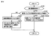
図19は、本発明の実施の形態2に従うハイブリッド車両における触媒暖機制御での第2暖機制御における制御処理を説明するフローチャートである。図19に示した制御処理は、たとえば、触媒暖機制御の実行中に、制御装置200によって所定の制御周期毎に繰返し実行される。
FIG. 19 is a flowchart illustrating a control process in the second warm-up control in the catalyst warm-up control in the hybrid vehicle according to the second embodiment of the present invention. For example, the control process shown in FIG. 19 is repeatedly executed by the
図19を参照して、制御装置200は、図14と同様のステップS100により、第2暖機制御を実施中であるかどうかを判定する。制御装置200は、第2暖機制御中(S100のYES判定時)には、ステップS150に処理を進めて、吸気バルブ118の作動特性の変化が制限されている状態であるかどうかを判定する。
Referring to FIG. 19,
たとえば、ステップS150は、VVL装置400(400A)に対する吸気バルブのリフト量および作用角の指令値に対して、VVL位置センサ311による検出値Lvが追従しない場合にYES判定とされる。ステップS150は、VVL装置400(400A)の故障による作動特性が完全に固定される場合に加えて、上述のように、低温時の固着ないし摩擦抵抗の増大、あるいは、異物の一時的な存在等によって、作動特性が一時的に固定された状況においても、YES判定とされ得る。
For example, step S150 is determined to be YES when the detected value Lv by the
制御装置200は、吸気バルブ118の作動特性の変化が制限された状態である場合(S150のYES判定時)は、ステップS200(図14)またはS200♯(図17)により、実施の形態1で説明したように、第2暖機制御中における吸気バルブ118の作動特性(現在値)に応じて、エンジン出力(第2運転パワーP2)を決定する。
When the change in the operating characteristic of
これに対して、制御装置200は、吸気バルブ118の作動特性の制御が正常である場合(S250のNO判定時)には、ステップS300に処理を進めて、触媒暖機条件から、第2暖機制御中におけるエンジン出力(第2運転パワーP2)を設定する。
On the other hand, when the control of the operation characteristic of
実施の形態1でも説明したように、第2暖機制御中におけるエンジン出力は、S/C触媒112Sの排気浄化能力を超えない範囲に設定する必要がある。一方で、S/C触媒112Sの排気浄化能力は、触媒温度の上昇に応じて高まる。したがって、触媒温度の温度による触媒浄化率の上昇に応じて、エンジン出力(第2運転パワーP2)を上昇させる態様とすれば、触媒暖機制御の所要時間の短縮が期待できる。 As described in the first embodiment, the engine output during the second warm-up control needs to be set in a range that does not exceed the exhaust purification capacity of the S / C catalyst 112S. On the other hand, the exhaust purification capacity of the S / C catalyst 112S increases as the catalyst temperature increases. Therefore, shortening the time required for catalyst warm-up control can be expected if the engine output (second operating power P2) is increased in accordance with the increase in the catalyst purification rate due to the catalyst temperature.
したがって、ステップS300では、たとえば、図20に示されるように触媒温度に応じて、第2運転パワーP2を可変に設定することができる。 Therefore, in step S300, for example, as shown in FIG. 20, the second operating power P2 can be variably set according to the catalyst temperature.
図20を参照して、触媒暖機条件から第2暖機制御時のエンジン出力を設定する場合には、触媒温度が高いほど、第2運転パワーP2は高く設定される。あるいは、触媒温度を直接用いるのではなく、触媒温度に基づいて推定される図11等に示された触媒浄化率(中央浄化率)に対応させて第2運転パワーP2を設定してもよい。 Referring to FIG. 20, when setting the engine output during the second warm-up control from the catalyst warm-up condition, the second operating power P2 is set higher as the catalyst temperature is higher. Alternatively, instead of directly using the catalyst temperature, the second operating power P2 may be set in correspondence with the catalyst purification rate (central purification rate) shown in FIG. 11 and the like estimated based on the catalyst temperature.
再び図19を参照して、制御装置200は、ステップS310では、ステップS300で設定された第2運転パワーP2に応じた吸気バルブ118の作動特性を、VVL装置400(400A)の指令値に設定する。たとえば、図13に示された特性線500に従って逆算することによって、第2運転パワーP2に対する吸気バルブ118の作動特性を選択するような指令値を設定することができる。
Referring to FIG. 19 again, in step S310,
これにより、VVL装置400(400A)が、当該指令値に従って動作することにより、吸気バルブの作動特性(リフト量および作用角)は、ステップS300で設定されたエンジン出力(第2運転パワーP2)に対して、エミッションまたは燃費の悪化を招かないような適正値に制御することができる。 As a result, when the VVL device 400 (400A) operates according to the command value, the operating characteristics (lift amount and operating angle) of the intake valve are set to the engine output (second operating power P2) set in step S300. On the other hand, it can be controlled to an appropriate value that does not cause a deterioration in emission or fuel consumption.
このように、実施の形態2に従うハイブリッド車両では、吸気バルブ118の作動特性の制御が正常である場合には、触媒暖機条件の面から第2暖機制御におけるエンジン出力(第2運転パワーP2)を設定することができる。これにより、実施の形態1での効果に加えて、触媒暖機制御の所要時間の短縮を図ることができる。
As described above, in the hybrid vehicle according to the second embodiment, when the control of the operation characteristic of
なお、本実施の形態2に従うハイブリッド車両における触媒暖機制御についても、実施の形態1と同様に、吸気バルブ118の作動特性(リフト量および作用角)が変更される態様(連続的/段階的、および、段階的に変更する際の段階数)を限定することなく適用することができる。
As for the catalyst warm-up control in the hybrid vehicle according to the second embodiment, as in the first embodiment, the operation characteristics (lift amount and working angle) of the
[その他の変形例]
上記の実施の形態1,2においては、排気浄化装置を、前段のS/C触媒112Sと、後段のU/F触媒112Uとによって構成し(図2)、S/C触媒112Sについて、S/C触媒112Sの端面浄化率が100%に達すると、第1暖機制御から第2暖機制御に切替わるものとし、S/C触媒112Sの中央浄化率が100%に達すると、触媒暖機制御(第2暖機制御)から通常制御に切替わるものとした。
[Other variations]
In the first and second embodiments, the exhaust purification device is configured by the front stage S / C catalyst 112S and the rear stage U /
このような構成に代えて、前段のS/C触媒112Sの浄化率(中央浄化率)が100%に達すると、第1暖機制御から第2暖機制御に切替わるものとし、後段のU/F触媒112Uの浄化率(中央浄化率)が100%に達すると、触媒暖機制御(第2暖機制御)から通常制御に切替わるようにしてもよい。
Instead of such a configuration, when the purification rate (central purification rate) of the S / C catalyst 112S in the front stage reaches 100%, the first warm-up control is switched to the second warm-up control, and the U When the purification rate (central purification rate) of the /
あるいは、図21に示すように、排気浄化装置をS/C触媒112SとU/F触媒112Uとに分けることなく1つの触媒112Vによって構成し、触媒112Vの端面浄化率が100%に達すると、第1暖機制御から第2暖機制御に切替わるものとし、触媒112Vの中央浄化率が100%に達すると、触媒暖機制御(第2暖機制御)から通常制御に切替わるようにしてもよい。
Alternatively, as shown in FIG. 21, when the exhaust purification device is configured by one
なお、上記の実施の形態1,2においては、吸気バルブ118の作動特性としてリフト量とともに作用角が制御される場合を説明したが、この発明は、吸気バルブ118の作動特性としてリフト量のみが制御可能(変更可能)な構成にも適用可能であり、吸気バルブ118の作動特性として作用角のみが制御可能(変更可能)な構成にも適用可能である。吸気バルブ118の作動特性としてリフト量および作用角のいずれかが制御可能(変更可能)な構成においても、吸気バルブ118のリフト量および作用角の双方が変更可能である場合と同様な効果を得ることができる。なお、吸気バルブ118のリフト量および作用角のいずれかのみが制御可能(変更可能)な構成は、周知の技術を利用して実現することができる。
In the first and second embodiments, the case where the operating angle is controlled together with the lift amount as the operating characteristic of the
吸気バルブ118のリフト量および作用角のいずれか一方のみが制御可能(変更可能)な構成に対しては、当該一方を検出するようにVVL位置センサ311が配置されるとともに、本実施の形態においてリフト量および作用角の両方について判定したものを当該一方についてのみ判定することで、同様の触媒暖機制御を適用することができる。このように、吸気バルブ118の作動特性としてリフト量および作用角の少なくとも一方を、連続的(無段階)ないし離散的(段階的)に変更可能な可変動弁機構を具備するハイブリッド車両に対して、本発明の適用が可能である。
For a configuration in which only one of the lift amount and working angle of
また、上記においては、動力分割装置4によりエンジン100の動力を駆動輪6とモータジェネレータMG1,MG2とに分割して伝達可能なシリーズ/パラレル型のハイブリッド車両について説明したが、この発明は、その他の形式のハイブリッド車両にも適用可能である。すなわち、たとえば、モータジェネレータMG1を駆動するためにのみエンジン100を用い、モータジェネレータMG2でのみ車両の駆動力を発生する、いわゆるシリーズ型のハイブリッド車両や、エンジン100が生成した運動エネルギーのうち回生エネルギーのみが電気エネルギーとして回収されるハイブリッド車両、エンジンを主動力として必要に応じてモータがアシストするモータアシスト型のハイブリッド車両などにもこの発明は適用可能である。また、モータを切り離してエンジンのみの動力によって走行するハイブリッド車両にもこの発明は適用可能である。
In the above description, the series / parallel type hybrid vehicle in which the power of the
また、上記の各実施の形態においては、制御装置200は、エンジン100の出力について、エンジン100のパワーを制御(第1または第2の運転パワーに制御)するものとしたが、エンジン100のトルクを制御してもよい(トルクデマンド制御)。すなわち、制御装置200は、第1暖機制御では、エンジン100が第1のトルクを出力するようにエンジン100を運転し、第2暖機制御では、エンジン100が第2のトルク(第2のトルク>第1のトルク)を出力するようにエンジン100を運転するようにしてもよい。こ
の場合、第1暖機制御では、エンジン100のトルクが第1のトルクとなるように第1運転ポイントが設定され、第2暖機制御では、エンジン100のトルクが第2のトルクとなるように第2運転ポイントが設定されるように、触媒暖機制御におけるエンジン出力が制御される。
Further, in each of the above embodiments, the
なお、上記において、モータジェネレータMG2は、この発明における「電動機」の一実施例に対応し、エンジン100,100♯は、この発明における「内燃機関」の一実施例に対応する。また、VVL装置400,400Aは、この発明における「可変動弁装置」の一実施例に対応する。さらに、図13に示された特性点501〜503および特性線500は、この発明における「所定の特性関係」の一実施例に対応する。
In the above, motor generator MG2 corresponds to an embodiment of “electric motor” in the present invention, and
今回開示された各実施の形態は、適宜組合わせて実施することも予定されている。そして、今回開示された実施の形態は、すべての点で例示であって制限的なものではないと考えられるべきである。本発明の範囲は、上記した実施の形態の説明ではなくて特許請求の範囲によって示され、特許請求の範囲と均等の意味および範囲内でのすべての変更が含まれることが意図される。 The embodiments disclosed this time are also scheduled to be implemented in appropriate combinations. The embodiment disclosed this time should be considered as illustrative in all points and not restrictive. The scope of the present invention is shown not by the above description of the embodiments but by the scope of claims for patent, and is intended to include meanings equivalent to the scope of claims for patent and all modifications within the scope.
1 ハイブリッド車両、4 動力分割装置、5 減速機、6 駆動輪、10 蓄電装置、100,100A エンジン、104 スロットルバルブ、106 シリンダ、108 インジェクタ、110 点火プラグ、112 三元触媒、112S,112U,112V 触媒、114 ピストン、116 クランクシャフト、118 吸気バルブ、120 排気バルブ、122,124 カム、128 ロッカアーム、130 カムシャフト、140 通路、142 バルブ、200 制御装置、300 カム角センサ、302 クランク角センサ、304 ノックセンサ、306 スロットル開度センサ、309 水温センサ、311 VVL位置センサ、312 スロットルモータ、400,400A VVL装置、410 駆動軸(VVL装置)、412 係止ピン、420 支持パイプ、430 入力アーム、432 アーム部、434 ローラ部、440 揺動カム、442 ノーズ部、444 カム面、450 スライダギヤ、452,454 ヘリカルギヤ、500,510,520 特性線、501,502,503 特性点、Lv 検出値(VVL位置センサ)、MG1,MG2 モータジェネレータ、Ne エンジン回転数、P1 第1運転パワー、P2 第2運転パワー、Pe エンジンパワー、R1,R2,R3 領域、Tw 冷却水温度、VSS 車速。
DESCRIPTION OF
Claims (7)
吸気バルブの作動特性としてリフト量および作用角の少なくとも一方を制御するための可変動弁装置を有する内燃機関と、
触媒を用いて前記内燃機関の排気を浄化する排気浄化装置と、
前記排気浄化装置の触媒の暖機を行なう触媒暖機制御を実行する制御装置とを備え、
前記触媒暖機制御は、
前記内燃機関を第1の運転ポイントで運転する第1の暖機制御と、
前記第1の暖機制御の実行後、走行に要求される駆動力に拘わらず、前記第1の運転ポイントよりも前記内燃機関の出力が大きい第2の運転ポイントで前記内燃機関を運転する第2の暖機制御とを含み、
前記制御装置は、前記第1の暖機制御の実行中は、前記第2の暖機制御の実行中よりも前記内燃機関の点火時期を遅角側にして前記内燃機関を運転し、
前記第2の暖機制御の実行中において、前記内燃機関の出力および前記吸気バルブの作動特性は、前記内燃機関の出力および前記作動特性を対応付ける所定の特性関係に従って設定され、
前記可変動弁装置は、前記作動特性を、第1の特性と、前記作動特性が前記第1の特性であるときよりも前記リフト量および前記作用角の少なくとも一方が大きい第2の特性とに変更可能に構成され、
前記特性関係は、前記作動特性が前記第2の特性であるときの前記内燃機関の出力が、前記作動特性が前記第1の特性であるときの前記内燃機関の出力よりも低くなるように定められる、ハイブリッド車両。 An electric motor for generating vehicle driving force;
An internal combustion engine having a variable valve system for controlling at least one of a lift amount and a working angle as an operation characteristic of the intake valve;
An exhaust emission control device for purifying exhaust gas of the internal combustion engine using a catalyst;
A control device for performing catalyst warm-up control for warming up the catalyst of the exhaust purification device,
The catalyst warm-up control is
First warm-up control for operating the internal combustion engine at a first operating point;
After the first warm-up control is executed, the internal combustion engine is operated at a second operating point where the output of the internal combustion engine is larger than the first operating point, regardless of the driving force required for traveling. 2 warm-up control,
The control device operates the internal combustion engine during the execution of the first warm-up control with the ignition timing of the internal combustion engine retarded as compared with the execution of the second warm-up control,
During the execution of the second warm-up control, the output of the internal combustion engine and the operating characteristic of the intake valve are set according to a predetermined characteristic relationship that associates the output of the internal combustion engine and the operating characteristic,
In the variable valve operating apparatus, the operating characteristic is a first characteristic and a second characteristic in which at least one of the lift amount and the operating angle is larger than when the operating characteristic is the first characteristic. Configured to be modifiable,
The characteristic relationship is determined such that the output of the internal combustion engine when the operating characteristic is the second characteristic is lower than the output of the internal combustion engine when the operating characteristic is the first characteristic. A hybrid vehicle.
吸気バルブの作動特性としてリフト量および作用角の少なくとも一方を制御するための可変動弁装置を有する内燃機関と、
触媒を用いて前記内燃機関の排気を浄化する排気浄化装置と、
前記排気浄化装置の触媒の暖機を行なう触媒暖機制御を実行する制御装置とを備え、
前記触媒暖機制御は、
前記内燃機関を第1の運転ポイントで運転する第1の暖機制御と、
前記第1の暖機制御の実行後、走行に要求される駆動力に拘わらず、前記第1の運転ポイントよりも前記内燃機関の出力が大きい第2の運転ポイントで前記内燃機関を運転する第2の暖機制御とを含み、
前記制御装置は、前記第1の暖機制御の実行中は、前記第2の暖機制御の実行中よりも前記内燃機関の点火時期を遅角側にして前記内燃機関を運転し、
前記第2の暖機制御の実行中において、前記内燃機関の出力および前記吸気バルブの作動特性は、前記内燃機関の出力および前記作動特性を対応付ける所定の特性関係に従って設定され、
前記可変動弁装置は、前記吸気バルブの作動特性を、第1の特性と、前記作動特性が前記第1の特性であるときよりも前記リフト量および前記作用角の少なくとも一方が大きい第2の特性と、前記作動特性が前記第2の特性であるときよりも前記リフト量および前記作用角の少なくとも一方が大きい第3の特性とのうちのいずれかに切替可能に構成され、 前記特性関係は、前記作動特性が前記第2の特性であるときの前記内燃機関の出力が、前記作動特性が前記第1の特性であるときの前記内燃機関の出力よりも低くなり、かつ、前記作動特性が前記第3の特性であるときの前記内燃機関の出力が、前記作動特性が前記第2の特性であるときの前記内燃機関の出力よりも低くなるように定められる、ハイブリッド車両。 An electric motor for generating vehicle driving force;
An internal combustion engine having a variable valve system for controlling at least one of a lift amount and a working angle as an operation characteristic of the intake valve;
An exhaust emission control device for purifying exhaust gas of the internal combustion engine using a catalyst;
A control device for performing catalyst warm-up control for warming up the catalyst of the exhaust purification device,
The catalyst warm-up control is
First warm-up control for operating the internal combustion engine at a first operating point;
After the first warm-up control is executed, the internal combustion engine is operated at a second operating point where the output of the internal combustion engine is larger than the first operating point, regardless of the driving force required for traveling. 2 warm-up control,
The control device operates the internal combustion engine during the execution of the first warm-up control with the ignition timing of the internal combustion engine retarded as compared with the execution of the second warm-up control,
During the execution of the second warm-up control, the output of the internal combustion engine and the operating characteristic of the intake valve are set according to a predetermined characteristic relationship that associates the output of the internal combustion engine and the operating characteristic,
The variable valve device has a first characteristic and a second characteristic in which at least one of the lift amount and the working angle is larger than that when the first characteristic and the first characteristic are the first characteristic. Switching between the first characteristic and the third characteristic in which at least one of the lift amount and the working angle is larger than when the operating characteristic is the second characteristic. The output of the internal combustion engine when the operating characteristic is the second characteristic is lower than the output of the internal combustion engine when the operating characteristic is the first characteristic, and the operating characteristic is The hybrid vehicle, wherein the output of the internal combustion engine when the third characteristic is set is determined to be lower than the output of the internal combustion engine when the operating characteristic is the second characteristic.
前記第2の暖機制御の実行中において、前記吸気バルブの作動特性が変化すると、前記内燃機関の出力は、前記特性関係に従って、前記検出器によって検出された現在の前記作動特性に応じて変更される、請求項1または2に記載のハイブリッド車両。 A detector for detecting the operating characteristic changed by the variable valve gear;
When the operation characteristic of the intake valve changes during the execution of the second warm-up control, the output of the internal combustion engine is changed according to the current operation characteristic detected by the detector according to the characteristic relationship. The hybrid vehicle according to claim 1 or 2 , wherein:
前記可変動弁装置は、前記第2の暖機制御の実行中において、前記可変動弁装置による前記作動特性の変化が制限されていない場合には、前記触媒暖機制御のために設定された前記内燃機関の出力に応じて、前記特性関係に従って前記作動特性を変更する、請求項1〜3のいずれか1項に記載のハイブリッド車両。 When the change of the operation characteristic by the variable valve apparatus is restricted during execution of the second warm-up control, the control device responds to the current operation characteristic of the intake valve. And setting the output of the internal combustion engine according to the characteristic relationship,
The variable valve operating device is set for the catalyst warm-up control when the change of the operation characteristic by the variable valve operating device is not restricted during the execution of the second warm-up control. in response to said output of the internal combustion engine, changing the operating characteristics in accordance with the characteristic relation, the hybrid vehicle according to any one of claims 1-3.
前記第2の暖機制御は、前記触媒全体の暖機を行なうものである、請求項1〜5のいずれか1項に記載のハイブリッド車両。 The first warm-up control is to perform warm-up on the exhaust upstream side of the catalyst,
The hybrid vehicle according to any one of claims 1 to 5 , wherein the second warm-up control warms up the entire catalyst.
Priority Applications (5)
| Application Number | Priority Date | Filing Date | Title |
|---|---|---|---|
| JP2014063660A JP6213334B2 (en) | 2014-03-26 | 2014-03-26 | Hybrid vehicle |
| EP15717614.0A EP3122606B1 (en) | 2014-03-26 | 2015-03-25 | Hybrid vehicle, controller for hybrid vehicle, and control method for hybrid vehicle |
| US15/128,584 US9889842B2 (en) | 2014-03-26 | 2015-03-25 | Hybrid vehicle, controller for hybrid vehicle, and control method for hybrid vehicle |
| CN201580016342.5A CN106132798B (en) | 2014-03-26 | 2015-03-25 | Hybrid vehicle, the controller for hybrid vehicle and the control method for hybrid vehicle |
| PCT/IB2015/000391 WO2015145242A2 (en) | 2014-03-26 | 2015-03-25 | Hybrid vehicle, controller for hybrid vehicle, and control method for hybrid vehicle |
Applications Claiming Priority (1)
| Application Number | Priority Date | Filing Date | Title |
|---|---|---|---|
| JP2014063660A JP6213334B2 (en) | 2014-03-26 | 2014-03-26 | Hybrid vehicle |
Publications (2)
| Publication Number | Publication Date |
|---|---|
| JP2015182735A JP2015182735A (en) | 2015-10-22 |
| JP6213334B2 true JP6213334B2 (en) | 2017-10-18 |
Family
ID=52991887
Family Applications (1)
| Application Number | Title | Priority Date | Filing Date |
|---|---|---|---|
| JP2014063660A Active JP6213334B2 (en) | 2014-03-26 | 2014-03-26 | Hybrid vehicle |
Country Status (5)
| Country | Link |
|---|---|
| US (1) | US9889842B2 (en) |
| EP (1) | EP3122606B1 (en) |
| JP (1) | JP6213334B2 (en) |
| CN (1) | CN106132798B (en) |
| WO (1) | WO2015145242A2 (en) |
Families Citing this family (2)
| Publication number | Priority date | Publication date | Assignee | Title |
|---|---|---|---|---|
| FR3049249B1 (en) * | 2016-03-23 | 2019-06-14 | Renault S.A.S | METHOD OF CONTROLLING A TORQUE OF ELECTRICAL ASSISTANCE |
| JP6423026B2 (en) * | 2017-02-09 | 2018-11-14 | 本田技研工業株式会社 | Hybrid car |
Family Cites Families (21)
| Publication number | Priority date | Publication date | Assignee | Title |
|---|---|---|---|---|
| JP3622322B2 (en) | 1996-03-11 | 2005-02-23 | 株式会社日立製作所 | Valve drive device and engine |
| JP2003286869A (en) * | 2002-03-27 | 2003-10-10 | Toyota Motor Corp | Cylinder injection spark ignition internal combustion engine |
| JP4158507B2 (en) | 2002-12-05 | 2008-10-01 | トヨタ自動車株式会社 | Valve drive system for internal combustion engine |
| US6810844B2 (en) * | 2002-12-10 | 2004-11-02 | Delphi Technologies, Inc. | Method for 3-step variable valve actuation |
| JP2005009474A (en) * | 2003-05-26 | 2005-01-13 | Toyota Motor Corp | Power output apparatus and its control method |
| JP2005320911A (en) * | 2004-05-10 | 2005-11-17 | Toyota Motor Corp | Power output device, automobile having the power output device, and method of controlling the power output device |
| JP2008025550A (en) | 2006-07-25 | 2008-02-07 | Toyota Motor Corp | Controller of adjustable valve mechanism |
| JP4197038B2 (en) * | 2007-03-27 | 2008-12-17 | トヨタ自動車株式会社 | Hybrid vehicle and control method thereof |
| JP4183013B1 (en) * | 2007-05-15 | 2008-11-19 | トヨタ自動車株式会社 | Vehicle and control method thereof |
| JP5029288B2 (en) | 2007-10-29 | 2012-09-19 | 日産自動車株式会社 | Exhaust purification catalyst warm-up control device and warm-up control method |
| JP5003511B2 (en) * | 2008-01-25 | 2012-08-15 | トヨタ自動車株式会社 | Control device for internal combustion engine |
| JP5476748B2 (en) | 2009-03-09 | 2014-04-23 | 日産自動車株式会社 | Hybrid vehicle |
| JP5163811B2 (en) * | 2009-05-19 | 2013-03-13 | トヨタ自動車株式会社 | Hybrid vehicle and control method thereof |
| JP2011047296A (en) * | 2009-08-26 | 2011-03-10 | Honda Motor Co Ltd | Control device of internal combustion engine |
| JP5459144B2 (en) * | 2010-08-17 | 2014-04-02 | トヨタ自動車株式会社 | Hybrid car |
| JP2012117376A (en) | 2010-11-29 | 2012-06-21 | Hitachi Automotive Systems Ltd | Valve actuation apparatus of internal combustion engine and rockable cam to be used in the same |
| JP2013053610A (en) | 2011-09-06 | 2013-03-21 | Toyota Motor Corp | Variable valve device |
| JP5632882B2 (en) | 2012-07-09 | 2014-11-26 | 本田技研工業株式会社 | Catalyst warm-up control device for hybrid vehicle |
| JP2015116959A (en) * | 2013-12-19 | 2015-06-25 | トヨタ自動車株式会社 | Hybrid vehicle |
| JP5929884B2 (en) | 2013-12-19 | 2016-06-08 | トヨタ自動車株式会社 | Hybrid vehicle |
| JP5949806B2 (en) * | 2014-02-25 | 2016-07-13 | トヨタ自動車株式会社 | Hybrid vehicle |
-
2014
- 2014-03-26 JP JP2014063660A patent/JP6213334B2/en active Active
-
2015
- 2015-03-25 WO PCT/IB2015/000391 patent/WO2015145242A2/en active Application Filing
- 2015-03-25 EP EP15717614.0A patent/EP3122606B1/en not_active Not-in-force
- 2015-03-25 US US15/128,584 patent/US9889842B2/en active Active
- 2015-03-25 CN CN201580016342.5A patent/CN106132798B/en not_active Expired - Fee Related
Also Published As
| Publication number | Publication date |
|---|---|
| CN106132798A (en) | 2016-11-16 |
| JP2015182735A (en) | 2015-10-22 |
| WO2015145242A2 (en) | 2015-10-01 |
| EP3122606A2 (en) | 2017-02-01 |
| WO2015145242A3 (en) | 2016-03-17 |
| US9889842B2 (en) | 2018-02-13 |
| US20170120894A1 (en) | 2017-05-04 |
| EP3122606B1 (en) | 2018-07-04 |
| CN106132798B (en) | 2019-03-19 |
Similar Documents
| Publication | Publication Date | Title |
|---|---|---|
| JP5949806B2 (en) | Hybrid vehicle | |
| JP4315229B2 (en) | Hybrid vehicle | |
| JP5929884B2 (en) | Hybrid vehicle | |
| JP6004106B2 (en) | Control device for internal combustion engine | |
| JP6040913B2 (en) | Hybrid vehicle | |
| US20160288784A1 (en) | Hybrid vehicle, control device for hybrid vehicle, and control method for hybrid vehicle with controller for managing the output of a battery in case of engine decompression situation | |
| JP2015067265A (en) | Hybrid vehicle | |
| JP2015077867A (en) | Hybrid vehicle | |
| KR20160067745A (en) | Automobile | |
| JP5939221B2 (en) | Hybrid vehicle control device and hybrid vehicle control method | |
| JP2015116967A (en) | Hybrid vehicle | |
| JP5962640B2 (en) | Hybrid vehicle | |
| JP2015116959A (en) | Hybrid vehicle | |
| JP6213334B2 (en) | Hybrid vehicle | |
| JP6194906B2 (en) | Vehicle control device | |
| JP2014077363A (en) | Control device of hybrid vehicle | |
| JP2015058827A (en) | Hybrid vehicle and control method for hybrid vehicle | |
| JP2015150947A (en) | hybrid vehicle | |
| JP2015128934A (en) | Hybrid electric vehicle |
Legal Events
| Date | Code | Title | Description |
|---|---|---|---|
| A977 | Report on retrieval |
Free format text: JAPANESE INTERMEDIATE CODE: A971007 Effective date: 20160204 |
|
| A131 | Notification of reasons for refusal |
Free format text: JAPANESE INTERMEDIATE CODE: A131 Effective date: 20160209 |
|
| A521 | Written amendment |
Free format text: JAPANESE INTERMEDIATE CODE: A523 Effective date: 20160331 |
|
| A131 | Notification of reasons for refusal |
Free format text: JAPANESE INTERMEDIATE CODE: A131 Effective date: 20160913 |
|
| A521 | Written amendment |
Free format text: JAPANESE INTERMEDIATE CODE: A523 Effective date: 20161109 |
|
| A02 | Decision of refusal |
Free format text: JAPANESE INTERMEDIATE CODE: A02 Effective date: 20170418 |
|
| A521 | Written amendment |
Free format text: JAPANESE INTERMEDIATE CODE: A523 Effective date: 20170711 |
|
| A911 | Transfer of reconsideration by examiner before appeal (zenchi) |
Free format text: JAPANESE INTERMEDIATE CODE: A911 Effective date: 20170720 |
|
| TRDD | Decision of grant or rejection written | ||
| A01 | Written decision to grant a patent or to grant a registration (utility model) |
Free format text: JAPANESE INTERMEDIATE CODE: A01 Effective date: 20170822 |
|
| A61 | First payment of annual fees (during grant procedure) |
Free format text: JAPANESE INTERMEDIATE CODE: A61 Effective date: 20170904 |
|
| R151 | Written notification of patent or utility model registration |
Ref document number: 6213334 Country of ref document: JP Free format text: JAPANESE INTERMEDIATE CODE: R151 |