JP2012117376A - Valve actuation apparatus of internal combustion engine and rockable cam to be used in the same - Google Patents
Valve actuation apparatus of internal combustion engine and rockable cam to be used in the same Download PDFInfo
- Publication number
- JP2012117376A JP2012117376A JP2010264898A JP2010264898A JP2012117376A JP 2012117376 A JP2012117376 A JP 2012117376A JP 2010264898 A JP2010264898 A JP 2010264898A JP 2010264898 A JP2010264898 A JP 2010264898A JP 2012117376 A JP2012117376 A JP 2012117376A
- Authority
- JP
- Japan
- Prior art keywords
- valve
- lift
- cam
- valve opening
- region
- Prior art date
- Legal status (The legal status is an assumption and is not a legal conclusion. Google has not performed a legal analysis and makes no representation as to the accuracy of the status listed.)
- Pending
Links
Images


Classifications
-
- F—MECHANICAL ENGINEERING; LIGHTING; HEATING; WEAPONS; BLASTING
- F01—MACHINES OR ENGINES IN GENERAL; ENGINE PLANTS IN GENERAL; STEAM ENGINES
- F01L—CYCLICALLY OPERATING VALVES FOR MACHINES OR ENGINES
- F01L13/00—Modifications of valve-gear to facilitate reversing, braking, starting, changing compression ratio, or other specific operations
- F01L13/0015—Modifications of valve-gear to facilitate reversing, braking, starting, changing compression ratio, or other specific operations for optimising engine performances by modifying valve lift according to various working parameters, e.g. rotational speed, load, torque
- F01L13/0021—Modifications of valve-gear to facilitate reversing, braking, starting, changing compression ratio, or other specific operations for optimising engine performances by modifying valve lift according to various working parameters, e.g. rotational speed, load, torque by modification of rocker arm ratio
- F01L13/0026—Modifications of valve-gear to facilitate reversing, braking, starting, changing compression ratio, or other specific operations for optimising engine performances by modifying valve lift according to various working parameters, e.g. rotational speed, load, torque by modification of rocker arm ratio by means of an eccentric
Abstract
Description
本発明は、例えば内燃機関の動弁装置及び該動弁装置に用いられる揺動カムの改良技術に関する。 The present invention relates to a valve operating apparatus for an internal combustion engine, for example, and a technique for improving a swing cam used in the valve operating apparatus.
この種の従来の内燃機関の動弁装置としては種々提供されており、その1つとして本出願人が先に出願した以下の特許文献1に記載されているものが知られている。 Various types of conventional valve operating devices for internal combustion engines are provided, and one of them is described in the following Patent Document 1 filed earlier by the present applicant.
この動弁装置は、機関運転状態に応じて可変機構により吸気弁のバルブリフト量と作動角を可変にできるものであって、クランクシャフトから伝達された回転力を揺動運動に変換して揺動カムを揺動させることによって吸気弁を開閉作動させるようになっている。前記揺動カムのカム面のプロフィールは、ベースサークル領域では曲率半径が小さく、ランプ領域からカムノーズ側のリフト領域に向かって曲率半径が大きくなるように設定されている。 This valve operating device can change the valve lift amount and the operating angle of the intake valve by a variable mechanism according to the engine operating state, and converts the rotational force transmitted from the crankshaft into a swinging motion to swing. The intake valve is opened and closed by swinging the moving cam. The profile of the cam surface of the swing cam is set so that the radius of curvature is small in the base circle region and the radius of curvature increases from the ramp region toward the lift region on the cam nose side.
そして、前記可変機構によって前記揺動カムのカム面のバルブリフタに対する摺動位置を変化させて、バルブリフト量と作動角を同時に変化させるようになっている。 The variable mechanism changes the sliding position of the cam surface of the swing cam with respect to the valve lifter to change the valve lift and the operating angle simultaneously.
しかしながら、前記従来の動弁装置にあっては、吸気弁の作動角の増加に比例してバルブリフト量も大きくなってしまうため、バルブリフト量を小さくした状態で大きな作動角を得ることができなかった。 However, in the conventional valve operating apparatus, the valve lift amount increases in proportion to the increase in the operation angle of the intake valve, so that a large operating angle can be obtained with the valve lift amount reduced. There wasn't.
本発明は、前記従来の技術的課題に鑑みて案出されたもので、機関弁のバルブリフト量を小さく抑えた状態で作動角を大きくすることのできる内燃機関の動弁装置を提供することを目的としている。 The present invention has been devised in view of the above-described conventional technical problems, and provides a valve operating apparatus for an internal combustion engine capable of increasing the operating angle while keeping the valve lift amount of the engine valve small. It is an object.
請求項1に記載の発明は、クランクシャフトから回転力が伝達される駆動カムと、該駆動カムの回転運動を揺動運動に変換する伝達機構と、該伝達機構の揺動運動によって揺動して機関弁を開閉作動させる曲面状のカム面を有する揺動カムと、を備え、前記揺動カムのカム面は、前記機関弁を閉弁状態にするベースサークル領域から開弁リフト状態にするカムノーズ側の開弁小リフト領域と、該開弁小リフト領域からノーズトップ側に連続して延びる開弁中リフト領域及び開弁大リフト領域と、を有し、前記開弁中リフト領域における前記開弁小リフト領域との境界付近の部位の曲率半径を、前記開弁大リフト領域の曲率半径よりも小さく設定したことを特徴としている。 According to the first aspect of the present invention, there is provided a drive cam to which a rotational force is transmitted from the crankshaft, a transmission mechanism for converting the rotational motion of the drive cam into a rocking motion, and rocking by the rocking motion of the transmission mechanism. A swing cam having a curved cam surface for opening and closing the engine valve, and the cam surface of the swing cam is brought into a valve-opening lift state from a base circle region in which the engine valve is closed. A valve opening small lift region on the cam nose side, a valve opening middle lift region and a valve opening large lift region continuously extending from the valve opening small lift region to the nose top side, and the valve opening lift region in the valve opening middle lift region The radius of curvature of the portion near the boundary with the valve opening small lift region is set to be smaller than the radius of curvature of the large valve opening lift region.
本発明によれば、機関弁のバルブリフト量を小さく抑制した状態で大きな作動角を得ることが可能になる。 According to the present invention, it is possible to obtain a large operating angle in a state where the valve lift amount of the engine valve is suppressed to be small.
以下、本発明に係る内燃機関の動弁装置及びこの動弁装置に用いられる揺動カムの実施形態を図面に基づいて詳述する。この実施形態では、例えばV型6気筒の内燃機関の吸気側の動弁装置に適用したものを示している。 Embodiments of a valve operating apparatus for an internal combustion engine and a swing cam used in the valve operating apparatus according to the present invention will be described below in detail with reference to the drawings. In this embodiment, the present invention is applied to a valve operating device on the intake side of a V-type 6-cylinder internal combustion engine, for example.
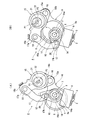
この動弁装置は、図1に示すように、シリンダヘッド1にバルブガイドを介して摺動自在に設けられて、バルブスプリング3,3によって閉方向に付勢された機関弁である一対の吸気弁2,2と、該各吸気弁2,2の作動特性であるバルブリフト量と作動角を同時に可変制御する可変機構4と、該可変機構4の作動位置を制御する制御機構5と、該制御機構5を回転駆動する駆動機構6と、を備えている。
As shown in FIG. 1, this valve operating apparatus is provided with a pair of intake valves that are slidably provided on a cylinder head 1 via a valve guide and are urged in a closing direction by
前記可変機構4は、シリンダヘッド1の上部に有する図外の軸受に回転自在に支持された中空状の駆動軸7と、該駆動軸7に圧入等により固設された偏心回転カムである駆動カム8と、駆動軸7の外周面に揺動自在に支持されて、各吸気弁2,2の上端部に配設されたバルブリフタ9、9の上面に摺接して各吸気弁2,2を開作動させる一気筒当たり2つの揺動カム10,10と、前記駆動カム8と揺動カム10,10との間に連係されて、駆動カム8の回転力を揺動運動に変換して揺動カム10,10に伝達する伝達機構と、を備えている。
The
前記駆動軸7は、機関前後方向に沿って配置されていると共に、一端部に設けられた図外の従動スプロケットや、該従動スプロケットに巻装されたタイミングチェーン等を介して機関のクランク軸から回転力が伝達されており、この回転方向は図1中、時計方向(矢印方向)に設定されている。
The
前記駆動カム8は、ほぼリング状を呈し、円環状のカム本体と、該カム本体の外端面に一体に設けられた筒状部とからなり、内部軸方向に駆動軸挿通孔が貫通形成されていると共に、カム本体の軸心Yが駆動軸7の軸心Xから径方向へ所定量だけオフセットしている。
The
前記両揺動カム10は、同一形状のほぼ雨滴状を呈し、円筒状のカムシャフト11の両端部に一体に設けられていると共に、該カムシャフト11を介して駆動軸7に揺動自在に支持されている。また、先端部のカムノーズ12側にピン孔13が貫通形成されていると共に、下面全体にはカム面14が形成されている。
The two
このカム面14は、図2及び図3に示すように、全体が曲率半径の異なる曲面状に形成されており、前記カムシャフト11側の基円面であるほぼ円弧状のベースサークル面14a(ベースサークル領域)と、該ベースサークル面14aからカムノーズ12側に連続して延びる緩衝部であるランプ面14b(ランプ領域)と、該ランプ面14bからカムノーズ12側に延びる正加速度領域である開弁小リフト面14cと、該開弁小リフト面14cからノーズトップ側に延びる負加速度領域である開弁中リフト面14d及び開弁大リフト面14eと、から主として構成されている。このカム面14のさらに具体的な構成は後述する。
As shown in FIGS. 2 and 3, the
前記ベースサークル面14aとランプ面14b、開弁小リフト面14c、開弁中リフト面14d及び開弁大リフト面14eが、揺動カム10の揺動位置に応じて各バルブリフタ9の冠面9aの所定位置に当接するようになっている。
The
前記伝達機構は、図6〜図8にも示すように、前記駆動軸7の上方に配置されたロッカアーム15と、該ロッカアーム15の一端部15aと駆動カム8とを連係するリンクアーム16と、ロッカアーム15の他端部15bと揺動カム10とを連係するリンクロッド17と、を備えている。
As shown in FIGS. 6 to 8, the transmission mechanism includes a
前記ロッカアーム15は、中央に有する筒状の基部が支持孔を介して後述する制御カム22に回転自在に支持されている。また、前記筒状基部の外端から突設された前記一端部15aには、ピン18が嵌入するピン孔が貫通形成されている一方、筒状基部の内端から突設された前記他端部15bには、リンクロッド17の上端部と連結するピン19が嵌入するピン孔が形成されている。
The
前記リンクアーム16は、比較的大径な円環状の基部16aと、該基部16aの外周面所定位置に突設された突出端16bと、を備え、基部16aの中央位置には、前記駆動カム8のカム本体が回転自在に嵌合する嵌合孔16cが形成されている一方、突出端16bには、前記ピン18が回転自在に挿通するピン孔が貫通形成されている。
The
前記リンクロッド17は、ロッカアーム15側が凹状のほぼく字形状に形成され、両端部17a,17bには前記ロッカアーム15の他端部15bと揺動カム10のカムノーズ12の各ピン孔に挿入した各ピン19,20の端部が回転自在に挿通するピン挿通孔が貫通形成されている。
The
なお、各ピン18〜20の一端部には、リンクアーム16やリンクロッド17の軸方向の移動を規制する図外のスナップリングがそれぞれ設けられている。
A snap ring (not shown) that restricts the movement of the
前記制御機構5は、駆動軸7の上方位置に同じ軸受に回転自在に支持された制御軸21と、該制御軸21の外周に固定されてロッカアーム15の支持孔に摺動自在に嵌入されて、ロッカアーム15の揺動支点となる制御カム22と、を備えている。
The
前記制御軸21は、駆動軸7と並行に機関前後方向に配設されていると共に、所定位置のジャーナル部21aが前記軸受のメインブラケットとサブブラケットとの間に回転自在に軸受されていると共に、前記駆動機構6によって正転あるいは逆転方向へ回転制御されるようになっている。
The
前記制御カム22は、円筒状を呈し、軸心P2位置が制御軸21の軸心P1から所定分だけ偏倚している。
The
また、前記制御軸21は、図1に示すように、一方側の最大回転位置と他方側の最大回転位置がストッパ機構によって規制されるようになっている。このストッパ機構は、シリンダヘッド1の上端部に突設された図外のストッパ壁と、制御軸21の外周面に一体的に固定された扇状のストッパ部材23とから構成され、前記ストッパ壁は、上端部のほぼ中央に半円形状の凹溝が形成されていると共に、該凹溝の両側上面に一対の第1、第2ストッパ部が形成されている。
Further, as shown in FIG. 1, the
前記駆動機構6は、図1に示すように、シリンダヘッド1の後端部に固定された図外のハウジングと、該ハウジングの一端部に固定された電動モータ24と、ハウジングの内部に収容されて、電動モータ24の回転力を前記制御軸21に伝達する減速機であるボール螺子機構25と、前記ハウジングの前記電動モータ24と反対側の位置に収容されて、前記ボール螺子機構25を介して前記制御軸21により吸気弁2,2を最小リフト量に制御する方向へ付勢する付勢手段であるコイルスプリング26と、から構成されている。
As shown in FIG. 1, the drive mechanism 6 is housed inside the housing, a housing (not shown) fixed to the rear end of the cylinder head 1, an
前記電動モ−タ24は、比例型のDCモータによって構成され、機関の運転状態を検出するコントロールユニット27から出力された制御電流によって正逆回転駆動するようになっている。
The
このコントロールユニット27は、クランク角センサやエアーフローメータ、水温センサや、制御軸21の回転位置を検出するポテンショメータ34等の各種のセンサからの検出信号をフィードバックして現在の機関運転状態を演算などにより検出して、前記電動モータ24に制御電流を出力している。
The
前記ボール螺子機構25は、前記ハウジング内に電動モータ24のモータ軸とほぼ同軸上に配置された出力軸であるボール螺子軸28と、該ボール螺子軸28の外周に螺合する移動部材であるボールナット29と、前記制御軸21の一端部に軸方向から連結された連係アーム30と、該連係アーム30と前記ボールナット29とを連係するリンク部材31と、から主として構成されている。
The
前記ボール螺子軸28は、両端部を除く外周面全体に所定幅のねじ部であるボール循環溝が螺旋状に連続して形成されていると共に、両端部がボールベアリング32によって回転自在に軸受けされている。
In the
ボール螺子軸28は、一端部の先端部と電動モータ24のモータ軸の先端部が図外の連結部材によって同軸上で軸方向移動可能にセレーション結合され、かかる結合によって電動モータ24の回転力を前記ボール螺子軸28に伝達すると共に、ボール螺子軸28の軸方向の僅かな移動を許容している。
In the
前記ボールナット29は、ほぼ円筒状に形成され、内周面に前記ボール循環溝と共同して複数のボールを転動自在に保持するガイド溝が螺旋状に連続して形成されている。また、このボールナット29は、各ボールを介してボール螺子軸28の回転運動を直線運動に変換しつつ軸方向の移動力が付与されるようになっていると共に、軸方向のほぼ中央位置に設けられた枢支ピン33によって前記リンク部材31が回動自在に連結されている。なお、このボールナット29は、例えば機関の停止時などでは、前記コイルスプリング26のばね力によって図1中、右側つまり電動モータ24側に付勢されて、制御軸21を介して吸気弁2,2を最小リフト、作動角に制御するようになっている。
The
前記リンク部材28は、板材をプレス成形によってほぼH字形状に形成され、平行な一対の細長い平板状のリンク部の一端部が前記ボールナット29の両側に跨がって配置されて前記枢支ピン31を介してボールナット29に回転自在に連結されている一方、他端部側が図外の前記枢支ピンを介して連係アーム30に回転自在に連結されている。
The
また、前記ボール螺子機構25は、図1に示すように、前記ボール螺子軸28の一方向の回転に伴ってボールナット29が図中、最大右方向へ移動した位置で、前述したように、前記制御軸21を介して吸気弁2,2のバルブリフト量を最小リフト量及び作動角を最小作動角に制御し、また、前記ボール螺子軸28の他方向の回転に伴ってボールナット29が図中、コイルスプリング26のばね力に抗して所定量だけ左方向へ移動した位置で、前記制御軸21を介して吸気弁2,2のバルブリフト量を中間リフト量及び作動角を中作動角に制御するようになっている。さらに、前記ボール螺子軸28の他方向の回転に伴ってボールナット29が、コイルスプリング26のばね力にさらに抗して図中、最大左方向へ移動した位置で、前記制御軸21を介して吸気弁2,2のバルブリフト量を最大リフト量及び作動角を最大作動角に制御するようになっている。
Further, as shown in FIG. 1, the
そして、前記各揺動カム10のカム面14は、前述したように、前記ベースサークル面14a(ベースサークル領域)と、ランプ面14b(ランプ領域)と、正加速度領域である開弁小リフト面14cと、負加速度領域である開弁中リフト面14d及び開弁大リフト面14eと、から主として構成されている。
As described above, the
前記ベースサークル面14aとランプ面14b及び開弁小リフト面14cとは、図2及び図3に示すように、それぞれ曲率半径が前記公報記載の従来のものと同じに設定されているが、前記開弁中リフト面14dと開弁大リフト面14eの曲率半径ρ2,ρ3が従来のもの(図3の一点鎖線)と異なっている。
As shown in FIGS. 2 and 3, the
すなわち、前記開弁小リフト面14cの曲率半径ρ1は、従来と同じくほぼ直線状に近い大きく形成されて、前記ベースサークル面14aやランプ面14bよりも大きく設定されている一方、前記開弁中リフト面14dと開弁大リフト面14eの各曲率半径ρ2,ρ3は従来のものよりも小さく設定されている。
That is, the radius of curvature ρ1 of the valve opening
すなわち、本実施形態の揺動カム10は、図3に示すように、従来の揺動カムに対して本実施形態の揺動カム10のカムプロフィール(曲率半径ρ)は、ベースサークル領域、ランプ領域、開弁小リフト面14cの正加速度領域の各領域では一致するが、負加速度領域における正加速度領域との境界付近の部位である負加速度領域の開始直後の開弁中リフト面14dは、その曲率半径ρ2が従来のものよりも小さく設定されている。また、前記開弁中リフト面14dからノーズトップ側へ連続して延びた開弁大リフト面14eの曲率半径ρ3は、前記開弁中リフト面14dよりも大きく設定されているが、全体として前記従来のものよりも小さく設定されている。
That is, as shown in FIG. 3, the
また、図3に示すカム面14中の角度a、b、cは、図4、図5の角度a、b、cとそれぞれ対応しており、これらは、図2に示す角度範囲θの範囲内と一致する。
Also, the angles a, b, and c in the
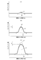
つまり、本実施形態の揺動カム10と従来の揺動カムとを比較した場合、前記正加速度領域である開弁小リフト面14cの角度aの最小作動角D1では、両者とも同じ特性になり、開弁中リフト面14dの角度bの中作動角D2では、後述する図9Bに示すように、ピークリフトL2が従来のものL2’よりα分だけ低下してリフト差が発生する。また、開弁大リフト面14eの角度cの最大作動角D3では、図9Cに示すように、ピークリフトL3が従来のものL3’よりβ分だけ低下して大きなリフト差が発生する。
That is, when the
以下、従来の揺動カムと本実施形態の揺動カム10におけるカム面14のプロフィール、特に開弁中リフト面14dと開弁大リフト面14eの設定を、揺動カム10の正、負の加速度や、図6〜図9に示す後述の可変機構4の作動中における揺動カム10の挙動などの関係から説明する。
Hereinafter, the profile of the
前記図2に示す揺動カム10の角度θは、揺動カム10の揺動中心点Oを通り、揺動カム10と共に回転する基準線Qとバルブリフタ9の冠面9aに対する垂線Rとの間に成す角度である。リフトyは、前記ベースサークル面14aと冠面9aとの間の距離である。また、図4に示す揺動カム10の加速度y’’は、バルブリフトyを角度θで2回微分したものである。
The angle θ of the
前記カム面14のプロフィールは、開弁リフトyと加速度y’’の特性をもって領域を区分される。つまり、開弁リフトyが0になるように設計されたベースサークル面14aと、該ベースサークル面14aから小さい加速度y’’を与えた後に、再び加速度y’’をほぼ0に戻して開弁リフトyを安定的に増加させるランプ面14bと、開弁リフトyを作動させるためのイベント領域であって加速度y’’が正となる正加速度領域である開弁小リフト面14cと、加速度y’’が負になる負加速度領域である開弁中、大リフト面14d、14eに区分される。
The profile of the
前記揺動カム10のカム面14の曲率半径と機関低回転時の揺動カム10とバルブリフタ9間の荷重F及び面圧Pは以下の式で表すことができる。
The radius of curvature of the

ここで、F0はバルブスプリング3のばね荷重、kはバルブスプリング3のばね定数、wは揺動カム10の巾長さ、Eは揺動カム10とバルブリフタ9の等価ヤング率である。
Here, F0 is the spring load of the
図4で示すように、負加速度領域の開始直後、つまり、開弁中リフト面14dの角度bにおいて曲率半径ρ2を最も小さくする。この角度bの領域では、曲率半径ρ2が小さくバルブリフト量L2が小さくなるため、バルブリフタ9の冠面9aに対する荷重Fが小さい。これによって、バルブリフタ9の冠面9aとの間の面圧Pが小さくなる。
As shown in FIG. 4, immediately after the start of the negative acceleration region, that is, at the angle b of the
開弁大リフト面14eの最大作動角D3での角度cでは、バルブリフト量L3を低下させるために、図4に示すように、角度aから角度bにおいて加速度y’’をより小さくする。すなわち、曲率半径を、最小の状態を維持するように加速度y’’を設定する。
At the angle c at the maximum operating angle D3 of the large valve
しかし、この場合、バルブリフト量が増加することによって、前記荷重Fが大きくなり面圧Pが増加する。この結果、カム面14とバルブリフタ9の冠面9aとの間の摩耗が発生し易くなる。このため、前記角度aから角度bとの間は、面圧Pが極度に増加しないように、加速度y’’を調整して曲率半径ρ3を曲率半径ρ2より大きく設定した。
However, in this case, as the valve lift increases, the load F increases and the surface pressure P increases. As a result, wear between the
以下、本実施形態に係る動弁装置の作動を説明する。まず、機関停止時には、前記コイルスプリング26のばね力でボールナット29が電動モータ24側に押圧付勢されて、自動的に前記制御軸21を前記ストッパ機構に規制される最大一方向に回転させて、吸気弁2,2のバルブリフト量を最小リフト量にすると共に、最小作動角側に制御する。
Hereinafter, the operation of the valve gear according to the present embodiment will be described. First, when the engine is stopped, the
機関始動後の機関運転状態の変化に応じて、前記コントロールユニット2727から出力された制御電流に応じて前記電動モータ24が正回転あるいは逆回転してボール螺子軸28を同方向に回転させて、前記ボールナット29を図1の左右いずれかの方向へ移動させる。これによって、前記制御軸21が制御カム22を正転あるいは逆転させる。
In response to a change in the engine operating state after the engine is started, the
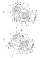
例えば、制御カム22が、最大一方向の回転によって軸心P2が図6A、Bに示すように、制御軸21の軸心P1の回りを同一半径で回転して、肉厚部が駆動軸7から右上方向に離間移動する。これにより、ロッカアーム15の他端部15bとリンクロッド17の枢支点は、駆動軸7に対して上方向へ移動し、このため、各揺動カム10は、リンクロッド17を介してカムノーズ12側が強制的に引き上げられて全体が時計方向へ回動する。
For example, when the
よって、駆動カム8が回転してリンクアーム16を介してロッカアーム15の一端部15aを押し上げると、その開弁リフトがリンクロッド17を介して各揺動カム10及び各バルブリフタ16に伝達されるが、その開度量は十分に小さくなる。これによって、吸気弁2,2は、バルブリフト量L1と作動角D1が図9Aに示すように最も小さくなる。この結果、各吸気弁2の開時期が遅くなると共に、閉時期が早くなる。
Therefore, when the
また、機関運転状態がさらに変化すると、制御カム22が、他方向の中間位置まで回転して軸心P2が図7A、Bに示すように、制御軸21の軸心P1の回りを同一半径で回転して、肉厚部が右回転して駆動軸7に僅かに近づく。これにより、ロッカアーム15の他端部15bとリンクロッド17の枢支点は、駆動軸7に対して僅かに下方向へ移動することから、各揺動カム10は、リンクロッド17を介してカムノーズ12側が強制的に引き下げられて全体が反時計方向へ回動する。
Further, when the engine operating state further changes, the
よって、駆動カム8が回転してリンクアーム16を介してロッカアーム15の一端部15aを押し上げると、その開弁リフトがリンクロッド17を介して各揺動カム10及び各バルブリフタ16に伝達され、その開弁リフトはやや大きくなる。これによって、吸気弁2,2は、図9Bに示すように、バルブリフト量がL2まで大きくなると共に、作動角もD2まで大きくなる。この結果、最小バルブリフト量L1のときよりも各吸気弁2の開時期が早くなると共に、閉時期が遅くなる。
Therefore, when the
このとき、前記作動角D2は、図9Bに示すように、従来の揺動カムを用いた場合と同じ大きさになるが、バルブリフト量L2(実線)は、従来の揺動カムによるバルブリフト量L2’(一点鎖線)よりもα分だけ低くなる。 At this time, as shown in FIG. 9B, the operating angle D2 is the same as that in the case of using the conventional swing cam, but the valve lift amount L2 (solid line) is the valve lift by the conventional swing cam. It is lower than the amount L2 ′ (dashed line) by α.
機関運転状態がさらに変化すると、制御カム22が、他方向の最大位置まで回転して軸心P2が図8A、Bに示すように、制御軸21の軸心P1の回りをさらに回転して、肉厚部がさらに右回転して駆動軸7に近づく。これにより、ロッカアーム15の他端部15bとリンクロッド17の枢支点は、駆動軸7に対してさらに下方向へ移動することから、各揺動カム10は、リンクロッド17を介してカムノーズ12側が強制的にさらに引き下げられて全体が反時計方向へ回動する。
When the engine operating state further changes, the
よって、駆動カム8が回転してリンクアーム16を介してロッカアーム15の一端部15aを押し上げると、その開弁リフトがリンクロッド17を介して各揺動カム10及び各バルブリフタ16に伝達され、その開弁リフトは十分に大きくなる。これによって、吸気弁2,2は、図9Cに示すように、バルブリフト量がL3まで最大に大きくなると共に、作動角もD3まで最大に大きくなる。この結果、中バルブリフト量L2、中作動角D2のときよりも各吸気弁2の開時期が最も早くなると共に、閉時期も最も遅くなる。
Therefore, when the
このとき、前記作動角D3は、図9Cに示すように、従来の揺動カムを用いた場合とほぼ同じ大きさになるが、最大バルブリフト量L3(実線)は、従来の揺動カムによるバルブリフト量L3’(一点鎖線)よりもβ分だけ低くなる。 At this time, as shown in FIG. 9C, the operating angle D3 is substantially the same as that in the case of using the conventional swing cam, but the maximum valve lift amount L3 (solid line) is determined by the conventional swing cam. It is lower than the valve lift amount L3 ′ (dashed line) by β.
つまり、バルブリフト量yと作動角との関係を示す図5の特性図からも明らかなように、バルブリフト量yは、最小作動角(角度a)から中間作動角(角度b)までは従来の揺動カムと同じ傾きγで推移するが、前記中間作動角(角度b)以降の最大作動角まではバルブリフト量が変化して、従来のもの(図中細線)よりも本実施形態の揺動カム(太い実線)の方が低いバルブリフト量になる。 In other words, as is clear from the characteristic diagram of FIG. 5 showing the relationship between the valve lift amount y and the operating angle, the valve lift amount y is conventionally from the minimum operating angle (angle a) to the intermediate operating angle (angle b). However, the amount of valve lift changes up to the maximum operating angle after the intermediate operating angle (angle b), and the present embodiment (thin line in the figure) is more than the conventional operating angle (thin line in the figure). The swing cam (thick solid line) has a lower valve lift.
このように、本実施形態では、図9B,Cに示すように、吸気弁2,2の中バルブリフト量L2と最大バルブリフト量L3(図4及び図5の太い実線)を、従来の各バルブリフト量(図4及び図5の細線)よりも低く抑えることができるのは、前述したように、前記各揺動カム10のカム面14中、従来のものに対して同じ正加速度領域を維持しながら負加速度領域の開始点直後である前記角度bの曲率半径ρ2を小さくしたことによるためであり、また、その後の角度cの曲率半径ρ3も従来のものよりは小さくしたことによるためである。
Thus, in this embodiment, as shown in FIGS. 9B and 9C, the intermediate valve lift amount L2 and the maximum valve lift amount L3 (thick solid lines in FIGS. As described above, the valve lift amount (thin line in FIGS. 4 and 5) can be kept lower than the conventional one in the
そして、機関始動後の機関のアイドリング運転時を含む低回転運転領域では、前述のように、コントロールユニット2727から出力された制御電流によって電動モータ24の回転に伴って各ボールがボール循環溝とガイド溝との間を転動しながらボールナット29を、図1中、最大左方向へ直線状に移動させる。これによって制御軸21が、制御カム22を他方向の最大位置まで回転させて軸心P2が図8A、Bに示すように、制御軸21の軸心P1の回りをさらに回転して、ロッカアーム15とリンクロッド17を介して各揺動カム10が、リンクロッド17を介してカムノーズ12側が強制的に引き下げられて全体が反時計方向へ回動する。
Then, in the low rotation operation region including the idling operation of the engine after the engine is started, as described above, each ball is guided to the ball circulation groove and the guide along with the rotation of the
よって、駆動カム8が回転してリンクアーム16を介してロッカアーム15の一端部15aを押し上げると、その開弁リフトがリンクロッド17を介して各揺動カム10及び各バルブリフタ16に伝達され、その開弁リフトは十分に大きくなる。これによって、吸気弁2,2は、図9Cに示すように、バルブリフト量がL3まで最大に大きくなると共に、作動角もD3まで最大に大きくなる。この結果、中バルブリフト量L2、中作動角D2のときよりも各吸気弁2の開時期が最も早くなると共に、閉時期も最も遅くなる。
Therefore, when the
このとき、前述したように、前記作動角D2、D3は、図9B、Cに示すように、従来の揺動カムを用いた場合とほぼ同じ大きさになるが、バルブリフト量は、中バルブリフト量L2と最大バルブリフト量L3で、従来の揺動カムによるバルブリフト量L2’、L3’(一点鎖線)よりもα、β分だけ低くなる。 At this time, as described above, the operating angles D2 and D3 are almost the same as those in the case of using the conventional swing cam as shown in FIGS. 9B and 9C. The lift amount L2 and the maximum valve lift amount L3 are lower by α and β than the valve lift amounts L2 ′ and L3 ′ (one-dot chain lines) by the conventional swing cam.
このように、機関低回転域では、吸気弁2,2の最大バルブリフト量L3を従来に比較して低く抑えつつ作動角を従来と同じく大きさの最大作動角D3を確保することができるので、揺動カム10のカム面14とバルブリフタ9の冠面9aとの間の面圧を低減できると共に、安定した燃焼状態が得られる。この結果、前記カム面14と冠面9aとの間のフリクションが十分に低減されて摩耗の発生を抑制できると共に、機関回転の安定化と燃費の向上が図れる。
Thus, in the low engine speed range, the maximum valve lift amount L3 of the
すなわち、いわゆるアトキンソンサイクルを実現するには、ピストンが吸気上死点を閉じる方法と、ピストンが吸気下死点を通過した後に吸気弁を閉じる方法があるが、前記ピストンが吸気下死点になる前に吸気弁を閉じると、異常燃焼が発生するおそれがある。そこで、低回転時に、吸気弁を、ピストンの吸気下死点よりも遅く閉じた場合には、バルブリフト量が大きくなりすぎてフリクションが増大してしまうおそれがある。 That is, in order to realize the so-called Atkinson cycle, there are a method in which the piston closes the intake top dead center and a method in which the piston closes the intake valve after passing through the intake bottom dead center, but the piston becomes the intake bottom dead center. If the intake valve is closed before, abnormal combustion may occur. Therefore, when the intake valve is closed later than the intake bottom dead center of the piston during low rotation, the valve lift amount may be too large and friction may increase.
そこで、本実施形態では、大きな作動角D3を確保することによって、吸気弁2,2の閉弁時期(IVC)を、ピストン下死点を通過した後とすることができるので、異常燃焼を抑制できる。また、このとき、吸気弁2,2の最大バルブリフト量L3における揺動カム10とバルブリフタ9との間の面圧Pを十分に低減できることから、前記両者9,10間のフリクションの増加を抑制できるのである。
Therefore, in this embodiment, by ensuring a large operating angle D3, the valve closing timing (IVC) of the
また、前記各揺動カム10のカムノーズ12側の曲率半径を、従来の揺動カムよりも小さく形成したことによって、各揺動カム10の軽量化が図れる慣性質量が小さくなるので、作動応答性の向上と振動の低減化が図れる。
Further, since the radius of curvature of each rocking
また、本実施形態では、前述のように、揺動カム10の最大バルブリフト量L3が、従来の揺動カムの最大バルブリフト量よりもβ分だけ小さくなるが、これは、例えば機関高回転高負荷時における高出力を得るために必要なバルブリフト量であって、機関性能の低下をもたらすものではなく、却って過度なバルブリフト量が抑制されることによるフリクションの低減や燃費の向上、さらには振動抑制効果が大きい。
In the present embodiment, as described above, the maximum valve lift amount L3 of the
本発明は、前記実施形態の構成に限定されるものではなく、前記揺動カム10のカム面14の開弁中、大リフト面14d、14eの曲率半径ρ2,ρ3を、機関に仕様や大きさなどに応じて任意に変更することも可能である。
The present invention is not limited to the configuration of the above embodiment, and the curvature radii ρ2 and ρ3 of the
また、前記吸気弁2,2の他に、排気弁に適用することも可能である。
In addition to the
また、前記可変機構4を備えない通常の動弁装置に適用することも可能であり、また、さらに異なる可変動弁装置に適用することも可能である。
Further, the present invention can be applied to a normal valve operating apparatus that does not include the
前記実施形態から把握される前記請求項以外の発明の技術的思想について以下に説明する。
〔請求項a〕請求項1に記載の内燃機関の動弁装置において、
前記開弁大リフト領域の曲率半径を、前記開弁中リフト領域の境界付近の部位よりも大きく設定したことを特徴とする内燃機関の動弁装置。
〔請求項b〕請求項1に記載の内燃機関の動弁装置において、
前記揺動カムの揺動加速度が正加速度領域から負加速度領域に変化したカム面の部位の曲率半径が、前記ベースサークル領域の曲率半径よりも小さく設定されていることを特徴とする内燃機関の動弁装置。
〔請求項c〕請求項2に記載の内燃機関の動弁装置において、
前記低回転低負荷時とは、アイドリング運転時であることを特徴とする内燃機関の動弁装置。
The technical ideas of the invention other than the claims ascertained from the embodiment will be described below.
[Claim a] The valve operating apparatus for an internal combustion engine according to claim 1,
A valve operating apparatus for an internal combustion engine, wherein a radius of curvature of the large valve opening lift region is set to be larger than a portion near a boundary of the lift region during valve opening.
[Claim b] In the valve operating apparatus for an internal combustion engine according to claim 1,
An internal combustion engine characterized in that a curvature radius of a portion of a cam surface where a swing acceleration of the swing cam has changed from a positive acceleration region to a negative acceleration region is set to be smaller than a curvature radius of the base circle region. Valve operating device.
[Claim c] In the valve operating apparatus for an internal combustion engine according to
The valve operating apparatus for an internal combustion engine, characterized in that the low rotation and low load is an idling operation.
この発明によれば、かかる低回転域で、吸気弁の閉時期をピストン下死点よりも遅く位置にできると共に、揺動カムとバルブリフタとの面圧を十分に小さくすることが可能になる。
〔請求項d〕請求項1に記載の内燃機関の動弁装置において、
前記カムノーズ側の開弁小リフト領域は、前記カム面のベースサークル領域と隣接するランプ領域から延びた正加速度領域であり、前記開弁中、大リフト領域は、前記正加速度領域を経た負加速度領域であることを特徴とする内燃機関の動弁装置。
〔請求項e〕請求項2に記載の内燃機関の動弁装置において、
前記カムノーズ側の開弁小リフト面は、前記カム面のベースサークル面と隣接するランプ面から延びた正加速度領域であり、前記開弁中、大リフト面は、前記正加速度領域を経た負加速度領域であることを特徴とする内燃機関の動弁装置。
〔請求項f〕請求項3に記載の内燃機関の動弁装置に用いられる揺動カムにおいて、
前記開弁中リフト領域の境界付近の部位からさらにノーズトップ側に延びた開弁大リフト領域の曲率半径を、前記境界付近の部位よりも大きく設定したことを特徴とする内燃機関の動弁装置に用いられる揺動カム。
〔請求項g〕請求項3に記載の内燃機関の動弁装置に用いられる揺動カムにおいて、
前記カムノーズ側の開弁小リフト領域は、前記カム面のベースサークル領域と隣接するランプ領域から延びた正加速度領域であると共に、前記開弁中、大リフト領域は、前記正加速度領域を経た負加速度領域であり、前記負加速度領域の開弁大リフト領域の曲率半径を、前記ベースサークル領域の曲率半径よりも小さく設定したことを特徴とする内燃機関の動弁装置に用いられる揺動カム。
According to the present invention, in such a low rotation range, the closing timing of the intake valve can be set later than the bottom dead center of the piston, and the surface pressure between the swing cam and the valve lifter can be sufficiently reduced.
[Claim d] In the valve operating apparatus for an internal combustion engine according to claim 1,
The cam nose side valve opening small lift region is a positive acceleration region extending from a ramp region adjacent to the base circle region of the cam surface, and during the valve opening, the large lift region is a negative acceleration through the positive acceleration region. A valve operating apparatus for an internal combustion engine characterized by being in a region.
[Claim e] In the valve operating apparatus for an internal combustion engine according to
The valve opening small lift surface on the cam nose side is a positive acceleration region extending from a ramp surface adjacent to the base circle surface of the cam surface, and during the valve opening, the large lift surface is a negative acceleration passing through the positive acceleration region. A valve operating apparatus for an internal combustion engine characterized by being in a region.
[Claim f] In the swing cam used in the valve operating apparatus for an internal combustion engine according to
A valve operating apparatus for an internal combustion engine, characterized in that a radius of curvature of a large valve opening lift region extending further toward the nose top side from a portion near the boundary of the lift region during valve opening is set larger than a portion near the boundary. Oscillating cam used for
[Claim g] In the swing cam used in the valve operating apparatus for an internal combustion engine according to
The cam nose side valve opening small lift region is a positive acceleration region extending from a ramp region adjacent to the base circle region of the cam surface, and during the valve opening, the large lift region is a negative acceleration region passing through the positive acceleration region. An oscillating cam used in a valve gear for an internal combustion engine, characterized in that the radius of curvature of a large lift region of the valve opening in the negative acceleration region is set to be smaller than the radius of curvature of the base circle region.
2…吸気弁(機関弁)
4…可変機構
5…制御機構
6…駆動機構
7…駆動軸
8…駆動カム
9…バルブリフタ
10…揺動カム
12…カムノーズ
14…カム面
14a…ベースサークル面(ベースサークル領域)
14b…ランプ面
14c…開弁小リフト面(正加速度領域)
14d…開弁中リフト面(負加速度領域)
14e…開弁大リフト面(負加速度領域)
15…ロッカアーム
16…リンクアーム
17…リンクロッド
21…制御軸
22…制御カム
24…電動モータ
25…ボール螺子機構(減速機)
26…コイルスプリング
2 ... Intake valve (engine valve)
DESCRIPTION OF
14b ...
14d ... Lifting surface during valve opening (negative acceleration range)
14e ... Valve opening large lift surface (negative acceleration range)
DESCRIPTION OF
26 ... Coil spring
Claims (3)
該駆動カムの回転運動を揺動運動に変換する伝達機構と、
該伝達機構の揺動運動によって揺動して機関弁を開閉作動させる曲面状のカム面を有する揺動カムと、を備え、
前記揺動カムのカム面は、前記機関弁を閉弁状態にするベースサークル領域から開弁リフト状態にするカムノーズ側の開弁小リフト領域と、該開弁小リフト領域からノーズトップ側に連続して延びる開弁中リフト領域及び開弁大リフト領域と、を有し、
前記開弁中リフト領域における前記開弁小リフト領域との境界付近の部位の曲率半径を、前記開弁大リフト領域の曲率半径よりも小さく設定したことを特徴とする内燃機関の動弁装置。 A drive cam to which rotational force is transmitted from the crankshaft;
A transmission mechanism for converting the rotational motion of the drive cam into a swing motion;
A swing cam having a curved cam surface that swings by the swing motion of the transmission mechanism to open and close the engine valve;
The cam surface of the swing cam is continuous from the base circle region for closing the engine valve to the valve opening lift state from the base circle region, and from the valve opening small lift region to the nose top side. A lift area during valve opening and a large lift area that opens,
A valve operating apparatus for an internal combustion engine, wherein a radius of curvature of a portion in the vicinity of a boundary between the lift region during valve opening and the small valve lift region is set smaller than a radius of curvature of the large valve lift region.
該駆動カムの回転運動を揺動運動に変換する伝達機構と、
該伝達機構の揺動運動によって揺動することによって機関弁を開閉作動させるカム面を有する揺動カムと、
前記伝達機構の姿勢を変化させることによって前記揺動カムの揺動状態を変化させて前記機関弁のバルブリフト量を可変にする可変機構と、
前記可変機構を駆動するアクチュエータと、
機関の作動状態に応じて前記アクチュエータを制御するコントローラと、
を備え、
前記コントローラは、機関の低回転低負荷時に、前記可変機構を介して機関弁が最大バルブリフト量及び最大作動角となるように前記アクチュエータに制御信号を出力し、
前記揺動カムのカム面は、前記機関弁を閉弁状態にするベースサークル面からランプ面を経てカムノーズ側に延びる開弁小リフト面と、該開弁小リフト面からノーズトップ側に連続して延びる開弁中リフト面及び開弁大リフト面と、を有し、
前記開弁中リフト面における前記開弁小リフト面との境界付近の部位の曲率半径を、前記開弁大リフト面よりも小さく設定すると共に、前記開弁大リフト面の曲率半径を前記開弁小リフト面よりも小さくしたことを特徴とする内燃機関の動弁装置。 A drive cam to which rotational force is transmitted from the crankshaft;
A transmission mechanism for converting the rotational motion of the drive cam into a swing motion;
A swing cam having a cam surface that opens and closes the engine valve by swinging by the swing motion of the transmission mechanism;
A variable mechanism for changing a valve lift amount of the engine valve by changing a swing state of the swing cam by changing a posture of the transmission mechanism;
An actuator for driving the variable mechanism;
A controller for controlling the actuator according to an operating state of the engine;
With
The controller outputs a control signal to the actuator so that the engine valve has a maximum valve lift amount and a maximum operating angle via the variable mechanism when the engine rotates at low speed and low load.
The cam surface of the oscillating cam continues from the base circle surface that closes the engine valve to the cam nose side through the ramp surface from the base circle surface, and continues from the valve opening small lift surface to the nose top side. A valve-opening lift surface and a valve-opening large lift surface,
The radius of curvature of a portion of the lift surface during valve opening near the boundary with the small valve opening surface is set to be smaller than that of the large valve opening surface, and the radius of curvature of the large valve opening surface is set to the valve opening surface. A valve operating apparatus for an internal combustion engine, characterized by being smaller than a small lift surface.
前記カム面は、前記機関弁を閉弁状態にするベースサークル領域から開弁リフト状態にするカムノーズ側の開弁小リフト領域と、該開弁小リフト領域からノーズトップ側に連続して延びる開弁中リフト領域及び開弁大リフト領域と、を有し、
前記開弁中リフト領域における前記開弁小リフト領域との境界付近の部位の曲率半径を、前記開弁大リフト領域の曲率半径よりも小さく設定したことを特徴とする内燃機関の動弁装置に用いられる揺動カム。 A swing cam used for a valve operating device of an internal combustion engine that opens and closes an engine valve by a cam surface by swinging,
The cam surface includes a valve opening small lift region on the cam nose side from the base circle region for closing the engine valve to a valve opening lift state, and an opening extending continuously from the valve opening small lift region to the nose top side. A valve lift area and a valve-open large lift area,
A valve operating apparatus for an internal combustion engine, characterized in that a radius of curvature of a portion in the vicinity of a boundary between the lift region during valve opening and the small valve lift region is set smaller than a radius of curvature of the large valve lift region. The swing cam used.
Priority Applications (2)
| Application Number | Priority Date | Filing Date | Title |
|---|---|---|---|
| JP2010264898A JP2012117376A (en) | 2010-11-29 | 2010-11-29 | Valve actuation apparatus of internal combustion engine and rockable cam to be used in the same |
| US13/290,588 US20120132163A1 (en) | 2010-11-29 | 2011-11-07 | Valve Actuation Apparatus of Internal Combustion Engine and Rockable Cam for Use with the Same |
Applications Claiming Priority (1)
| Application Number | Priority Date | Filing Date | Title |
|---|---|---|---|
| JP2010264898A JP2012117376A (en) | 2010-11-29 | 2010-11-29 | Valve actuation apparatus of internal combustion engine and rockable cam to be used in the same |
Publications (1)
| Publication Number | Publication Date |
|---|---|
| JP2012117376A true JP2012117376A (en) | 2012-06-21 |
Family
ID=46125789
Family Applications (1)
| Application Number | Title | Priority Date | Filing Date |
|---|---|---|---|
| JP2010264898A Pending JP2012117376A (en) | 2010-11-29 | 2010-11-29 | Valve actuation apparatus of internal combustion engine and rockable cam to be used in the same |
Country Status (2)
| Country | Link |
|---|---|
| US (1) | US20120132163A1 (en) |
| JP (1) | JP2012117376A (en) |
Cited By (13)
| Publication number | Priority date | Publication date | Assignee | Title |
|---|---|---|---|---|
| WO2015040474A1 (en) | 2013-09-19 | 2015-03-26 | Toyota Jidosha Kabushiki Kaisha | Hybrid vehicle, controller for hybrid vehicle and control method for hybrid vehicle for delivering power to an external device and optimizing startability and fuel consumption with a variable valve timing at the intake |
| WO2015049563A1 (en) | 2013-10-01 | 2015-04-09 | Toyota Jidosha Kabushiki Kaisha | Hybrid vehicle, controller for hybrid vehicle, and control method for hybrid vehicle for reducing the compression ration at start-up of the engine according a battery level |
| WO2015056064A1 (en) | 2013-10-16 | 2015-04-23 | Toyota Jidosha Kabushiki Kaisha | Hybrid vehicle, controller for a variable valve timing (lift and/or angle) device for the combustion engine of the hybrid vehicle, and control method for such hybrid vehicle |
| WO2015068012A1 (en) | 2013-11-08 | 2015-05-14 | Toyota Jidosha Kabushiki Kaisha | Hybrid vehicle, controller for hybrid vehicle, and control method for hybrid vehicle with a change of the switching conditions from a depleting mode to a sustaining mode |
| WO2015082967A1 (en) | 2013-12-03 | 2015-06-11 | Toyota Jidosha Kabushiki Kaisha | Hybrid vehicle, control device for hybrid vehicle, and control method for hybrid vehicle with controller for managing the output of a battery in case of engine decompression situation |
| WO2015082989A2 (en) | 2013-12-06 | 2015-06-11 | Toyota Jidosha Kabushiki Kaisha | Hybrid vehicle, control device for hybrid vehicle, and control method for hybrid vehicle |
| WO2015092510A2 (en) | 2013-12-19 | 2015-06-25 | Toyota Jidosha Kabushiki Kaisha | Hybrid vehicle, controller for hybrid vehicle, and control method for hybrid vehicle |
| WO2015121909A1 (en) | 2014-02-12 | 2015-08-20 | Toyota Jidosha Kabushiki Kaisha | Hybrid vehicle with variable valve timing failure detection with consequent reduction of engine output range range and increase of the state of charge |
| WO2015128721A2 (en) | 2014-02-25 | 2015-09-03 | Toyota Jidosha Kabushiki Kaisha | Hybrid vehicle and control method for hybrid vehicle |
| WO2015145242A2 (en) | 2014-03-26 | 2015-10-01 | Toyota Jidosha Kabushiki Kaisha | Hybrid vehicle, controller for hybrid vehicle, and control method for hybrid vehicle |
| US9487206B2 (en) | 2013-09-19 | 2016-11-08 | Toyota Jidosha Kabushiki Kaisha | Device and method for controlling a hybrid vehicle |
| US9527501B2 (en) | 2013-11-12 | 2016-12-27 | Toyoda Jidosha Kabushiki Kaisha | Hybrid vehicle |
| US9758162B2 (en) | 2013-09-20 | 2017-09-12 | Toyota Jidosha Kabushiki Kaisha | Hybrid vehicle, controller for hybrid vehicle, and control method for hybrid vehicle |
Families Citing this family (5)
| Publication number | Priority date | Publication date | Assignee | Title |
|---|---|---|---|---|
| JP5294156B2 (en) * | 2009-11-12 | 2013-09-18 | スズキ株式会社 | Variable valve operating device for internal combustion engine |
| WO2012105509A1 (en) * | 2011-01-31 | 2012-08-09 | 日産自動車株式会社 | Internal combustion engine |
| US9322352B2 (en) | 2012-05-14 | 2016-04-26 | GM Global Technology Operations LLC | System and method for preventing misfire during engine startup |
| US9249750B2 (en) * | 2012-11-08 | 2016-02-02 | GM Global Technology Operations LLC | System and method for controlling fuel injection when an engine is automatically started to decrease an engine startup period |
| US10099675B2 (en) | 2014-10-27 | 2018-10-16 | GM Global Technology Operations LLC | System and method for improving fuel economy and reducing emissions when a vehicle is decelerating |
Citations (10)
| Publication number | Priority date | Publication date | Assignee | Title |
|---|---|---|---|---|
| JPH07133708A (en) * | 1993-03-10 | 1995-05-23 | Toyota Motor Corp | Cam change-over mechanism in moving valve unit of internal combustion engine |
| JP2000213314A (en) * | 1999-01-20 | 2000-08-02 | Unisia Jecs Corp | Variable valve system for internal combustion engine |
| JP2000337114A (en) * | 1999-05-24 | 2000-12-05 | Unisia Jecs Corp | Valve system of internal combustion engine |
| JP2003041911A (en) * | 2001-07-27 | 2003-02-13 | Nissan Motor Co Ltd | Valve system for internal combustion engine |
| JP2005207261A (en) * | 2004-01-21 | 2005-08-04 | Green Hanto:Kk | Variable ivc output control valve mechanism |
| JP2007292051A (en) * | 2006-03-31 | 2007-11-08 | Mazda Motor Corp | Spark-ignition gasoline engine |
| JP2008101520A (en) * | 2006-10-18 | 2008-05-01 | Nissan Motor Co Ltd | Mirror cycle engine |
| JP2009085162A (en) * | 2007-10-02 | 2009-04-23 | Toyota Motor Corp | Control system for internal combustion engine |
| JP2009264272A (en) * | 2008-04-25 | 2009-11-12 | Nissan Motor Co Ltd | Torque discontinuity reducing device of engine |
| JP2010127249A (en) * | 2008-11-28 | 2010-06-10 | Toyota Motor Corp | Internal combustion engine |
Family Cites Families (5)
| Publication number | Priority date | Publication date | Assignee | Title |
|---|---|---|---|---|
| DE60004412T2 (en) * | 1999-02-05 | 2004-06-24 | Unisia Jecs Corp., Atsugi | Variable valve control device for an internal combustion engine |
| DE60110702T2 (en) * | 2000-08-22 | 2005-10-06 | Nissan Motor Co., Ltd., Yokohama | Engine with two rows of cylinders, each with a device for adjusting the valve timing and valve lift |
| JP3912147B2 (en) * | 2002-03-15 | 2007-05-09 | 日産自動車株式会社 | Variable valve operating device for internal combustion engine |
| JP4063026B2 (en) * | 2002-09-24 | 2008-03-19 | 日産自動車株式会社 | Control device for internal combustion engine |
| JP4827865B2 (en) * | 2008-01-30 | 2011-11-30 | 日立オートモティブシステムズ株式会社 | Variable valve operating device for internal combustion engine |
-
2010
- 2010-11-29 JP JP2010264898A patent/JP2012117376A/en active Pending
-
2011
- 2011-11-07 US US13/290,588 patent/US20120132163A1/en not_active Abandoned
Patent Citations (10)
| Publication number | Priority date | Publication date | Assignee | Title |
|---|---|---|---|---|
| JPH07133708A (en) * | 1993-03-10 | 1995-05-23 | Toyota Motor Corp | Cam change-over mechanism in moving valve unit of internal combustion engine |
| JP2000213314A (en) * | 1999-01-20 | 2000-08-02 | Unisia Jecs Corp | Variable valve system for internal combustion engine |
| JP2000337114A (en) * | 1999-05-24 | 2000-12-05 | Unisia Jecs Corp | Valve system of internal combustion engine |
| JP2003041911A (en) * | 2001-07-27 | 2003-02-13 | Nissan Motor Co Ltd | Valve system for internal combustion engine |
| JP2005207261A (en) * | 2004-01-21 | 2005-08-04 | Green Hanto:Kk | Variable ivc output control valve mechanism |
| JP2007292051A (en) * | 2006-03-31 | 2007-11-08 | Mazda Motor Corp | Spark-ignition gasoline engine |
| JP2008101520A (en) * | 2006-10-18 | 2008-05-01 | Nissan Motor Co Ltd | Mirror cycle engine |
| JP2009085162A (en) * | 2007-10-02 | 2009-04-23 | Toyota Motor Corp | Control system for internal combustion engine |
| JP2009264272A (en) * | 2008-04-25 | 2009-11-12 | Nissan Motor Co Ltd | Torque discontinuity reducing device of engine |
| JP2010127249A (en) * | 2008-11-28 | 2010-06-10 | Toyota Motor Corp | Internal combustion engine |
Cited By (20)
| Publication number | Priority date | Publication date | Assignee | Title |
|---|---|---|---|---|
| US9487206B2 (en) | 2013-09-19 | 2016-11-08 | Toyota Jidosha Kabushiki Kaisha | Device and method for controlling a hybrid vehicle |
| WO2015040474A1 (en) | 2013-09-19 | 2015-03-26 | Toyota Jidosha Kabushiki Kaisha | Hybrid vehicle, controller for hybrid vehicle and control method for hybrid vehicle for delivering power to an external device and optimizing startability and fuel consumption with a variable valve timing at the intake |
| US9758162B2 (en) | 2013-09-20 | 2017-09-12 | Toyota Jidosha Kabushiki Kaisha | Hybrid vehicle, controller for hybrid vehicle, and control method for hybrid vehicle |
| WO2015049563A1 (en) | 2013-10-01 | 2015-04-09 | Toyota Jidosha Kabushiki Kaisha | Hybrid vehicle, controller for hybrid vehicle, and control method for hybrid vehicle for reducing the compression ration at start-up of the engine according a battery level |
| WO2015056064A1 (en) | 2013-10-16 | 2015-04-23 | Toyota Jidosha Kabushiki Kaisha | Hybrid vehicle, controller for a variable valve timing (lift and/or angle) device for the combustion engine of the hybrid vehicle, and control method for such hybrid vehicle |
| WO2015068012A1 (en) | 2013-11-08 | 2015-05-14 | Toyota Jidosha Kabushiki Kaisha | Hybrid vehicle, controller for hybrid vehicle, and control method for hybrid vehicle with a change of the switching conditions from a depleting mode to a sustaining mode |
| US10065629B2 (en) | 2013-11-08 | 2018-09-04 | Toyota Jidosha Kabushiki Kaisha | Hybrid vehicle, controller for hybrid vehicle, and control method for hybrid vehicle with a change of the switching conditions from a depleting mode to a sustaining mode |
| US9527501B2 (en) | 2013-11-12 | 2016-12-27 | Toyoda Jidosha Kabushiki Kaisha | Hybrid vehicle |
| WO2015082967A1 (en) | 2013-12-03 | 2015-06-11 | Toyota Jidosha Kabushiki Kaisha | Hybrid vehicle, control device for hybrid vehicle, and control method for hybrid vehicle with controller for managing the output of a battery in case of engine decompression situation |
| WO2015082989A2 (en) | 2013-12-06 | 2015-06-11 | Toyota Jidosha Kabushiki Kaisha | Hybrid vehicle, control device for hybrid vehicle, and control method for hybrid vehicle |
| US9789865B2 (en) | 2013-12-06 | 2017-10-17 | Toyota Jidosha Kabushiki Kaisha | Hybrid vehicle, control device for hybrid vehicle, and control method for hybrid vehicle with throttle valve control according the temperature of the battery |
| DE112014005555B4 (en) * | 2013-12-06 | 2020-09-03 | Toyota Jidosha Kabushiki Kaisha | Hybrid vehicle, control unit for hybrid vehicle and control method for hybrid vehicle with throttle control according to the temperature of the battery |
| US9815452B2 (en) | 2013-12-19 | 2017-11-14 | Toyota Jidosha Kabushiki Kaisha | Hybrid vehicle, controller for hybrid vehicle, and control method for hybrid vehicle with two stages catalyst warm-up in relationship with variable intake valve timing |
| WO2015092510A2 (en) | 2013-12-19 | 2015-06-25 | Toyota Jidosha Kabushiki Kaisha | Hybrid vehicle, controller for hybrid vehicle, and control method for hybrid vehicle |
| US9725085B2 (en) | 2014-02-12 | 2017-08-08 | Toyota Jidosha Kabushiki Kaisha | Hybrid vehicle with variable valve timing failure detection with consequent reduction of engine output range range and increase of the state of charge |
| WO2015121909A1 (en) | 2014-02-12 | 2015-08-20 | Toyota Jidosha Kabushiki Kaisha | Hybrid vehicle with variable valve timing failure detection with consequent reduction of engine output range range and increase of the state of charge |
| WO2015128721A2 (en) | 2014-02-25 | 2015-09-03 | Toyota Jidosha Kabushiki Kaisha | Hybrid vehicle and control method for hybrid vehicle |
| US9909512B2 (en) | 2014-02-25 | 2018-03-06 | Toyota Jidosha Kabushiki Kaisha | Hybrid vehicle and control method for hybrid vehicle |
| WO2015145242A2 (en) | 2014-03-26 | 2015-10-01 | Toyota Jidosha Kabushiki Kaisha | Hybrid vehicle, controller for hybrid vehicle, and control method for hybrid vehicle |
| US9889842B2 (en) | 2014-03-26 | 2018-02-13 | Toyota Jidosha Kabushiki Kaisha | Hybrid vehicle, controller for hybrid vehicle, and control method for hybrid vehicle |
Also Published As
| Publication number | Publication date |
|---|---|
| US20120132163A1 (en) | 2012-05-31 |
Similar Documents
| Publication | Publication Date | Title |
|---|---|---|
| JP2012117376A (en) | Valve actuation apparatus of internal combustion engine and rockable cam to be used in the same | |
| JP4571161B2 (en) | Variable valve operating device for internal combustion engine | |
| JP2007040291A (en) | Variable valve gear for internal combustion engine | |
| JP2003172112A (en) | Variable valve system of internal combustion engine | |
| JP2007321653A (en) | Variable valve gear of internal combustion engine | |
| EP1911941A1 (en) | Variable Valve Timing Mechanism for Internal Combustion Engine | |
| JP4469341B2 (en) | Variable valve mechanism | |
| JP2017166365A (en) | Variable valve gear of internal combustion engine | |
| JP4878594B2 (en) | Variable valve operating device for internal combustion engine | |
| JP4027685B2 (en) | Variable valve operating apparatus for internal combustion engine and control mechanism used in the apparatus | |
| JP4109926B2 (en) | Variable valve operating device for internal combustion engine | |
| JP3880197B2 (en) | Valve operating device for internal combustion engine | |
| JP4933474B2 (en) | Valve operating device for internal combustion engine | |
| JP2007198387A (en) | Variable valve gear for internal combustion engine | |
| JP4860669B2 (en) | Variable valve operating device for internal combustion engine | |
| JP3699820B2 (en) | Valve operating device for internal combustion engine | |
| JP4142544B2 (en) | Valve operating device for internal combustion engine | |
| JP5533781B2 (en) | Variable valve operating device for internal combustion engine | |
| JP2008286145A (en) | Variable valve gear for internal combustion engine | |
| JP5189037B2 (en) | Valve device for internal combustion engine and cam used for the valve device | |
| JP4278607B2 (en) | Swing cam device | |
| JP2009281164A (en) | Variable valve gear of internal combustion engine | |
| JP4516453B2 (en) | Valve operating device for internal combustion engine | |
| JP2006233830A (en) | Valve gear of internal combustion engine | |
| JP4986900B2 (en) | Valve operating device for internal combustion engine |
Legal Events
| Date | Code | Title | Description |
|---|---|---|---|
| A521 | Request for written amendment filed |
Free format text: JAPANESE INTERMEDIATE CODE: A523 Effective date: 20120814 |
|
| A621 | Written request for application examination |
Free format text: JAPANESE INTERMEDIATE CODE: A621 Effective date: 20120814 |
|
| A977 | Report on retrieval |
Free format text: JAPANESE INTERMEDIATE CODE: A971007 Effective date: 20130130 |
|
| A131 | Notification of reasons for refusal |
Free format text: JAPANESE INTERMEDIATE CODE: A131 Effective date: 20130205 |
|
| A521 | Request for written amendment filed |
Free format text: JAPANESE INTERMEDIATE CODE: A523 Effective date: 20130405 |
|
| A02 | Decision of refusal |
Free format text: JAPANESE INTERMEDIATE CODE: A02 Effective date: 20130806 |