JP6208596B2 - Reaction cell and biochemical automatic analyzer - Google Patents
Reaction cell and biochemical automatic analyzer Download PDFInfo
- Publication number
- JP6208596B2 JP6208596B2 JP2014031886A JP2014031886A JP6208596B2 JP 6208596 B2 JP6208596 B2 JP 6208596B2 JP 2014031886 A JP2014031886 A JP 2014031886A JP 2014031886 A JP2014031886 A JP 2014031886A JP 6208596 B2 JP6208596 B2 JP 6208596B2
- Authority
- JP
- Japan
- Prior art keywords
- reaction cell
- thickness
- flat plates
- wall surfaces
- corner
- Prior art date
- Legal status (The legal status is an assumption and is not a legal conclusion. Google has not performed a legal analysis and makes no representation as to the accuracy of the status listed.)
- Active
Links
Images


Classifications
-
- G—PHYSICS
- G01—MEASURING; TESTING
- G01N—INVESTIGATING OR ANALYSING MATERIALS BY DETERMINING THEIR CHEMICAL OR PHYSICAL PROPERTIES
- G01N21/00—Investigating or analysing materials by the use of optical means, i.e. using sub-millimetre waves, infrared, visible or ultraviolet light
- G01N21/01—Arrangements or apparatus for facilitating the optical investigation
- G01N21/03—Cuvette constructions
-
- B—PERFORMING OPERATIONS; TRANSPORTING
- B01—PHYSICAL OR CHEMICAL PROCESSES OR APPARATUS IN GENERAL
- B01L—CHEMICAL OR PHYSICAL LABORATORY APPARATUS FOR GENERAL USE
- B01L3/00—Containers or dishes for laboratory use, e.g. laboratory glassware; Droppers
- B01L3/50—Containers for the purpose of retaining a material to be analysed, e.g. test tubes
- B01L3/508—Containers for the purpose of retaining a material to be analysed, e.g. test tubes rigid containers not provided for above
-
- G—PHYSICS
- G01—MEASURING; TESTING
- G01N—INVESTIGATING OR ANALYSING MATERIALS BY DETERMINING THEIR CHEMICAL OR PHYSICAL PROPERTIES
- G01N21/00—Investigating or analysing materials by the use of optical means, i.e. using sub-millimetre waves, infrared, visible or ultraviolet light
- G01N21/17—Systems in which incident light is modified in accordance with the properties of the material investigated
- G01N21/25—Colour; Spectral properties, i.e. comparison of effect of material on the light at two or more different wavelengths or wavelength bands
- G01N21/27—Colour; Spectral properties, i.e. comparison of effect of material on the light at two or more different wavelengths or wavelength bands using photo-electric detection ; circuits for computing concentration
-
- G—PHYSICS
- G01—MEASURING; TESTING
- G01N—INVESTIGATING OR ANALYSING MATERIALS BY DETERMINING THEIR CHEMICAL OR PHYSICAL PROPERTIES
- G01N35/00—Automatic analysis not limited to methods or materials provided for in any single one of groups G01N1/00 - G01N33/00; Handling materials therefor
-
- B—PERFORMING OPERATIONS; TRANSPORTING
- B01—PHYSICAL OR CHEMICAL PROCESSES OR APPARATUS IN GENERAL
- B01L—CHEMICAL OR PHYSICAL LABORATORY APPARATUS FOR GENERAL USE
- B01L2200/00—Solutions for specific problems relating to chemical or physical laboratory apparatus
- B01L2200/12—Specific details about manufacturing devices
-
- B—PERFORMING OPERATIONS; TRANSPORTING
- B01—PHYSICAL OR CHEMICAL PROCESSES OR APPARATUS IN GENERAL
- B01L—CHEMICAL OR PHYSICAL LABORATORY APPARATUS FOR GENERAL USE
- B01L2300/00—Additional constructional details
- B01L2300/08—Geometry, shape and general structure
- B01L2300/0848—Specific forms of parts of containers
- B01L2300/0858—Side walls
Description
本発明は、生化学自動分析装置に用いる反応セル、及びそれを用いた生化学自動分析装置に関する。 The present invention relates to a reaction cell used in a biochemical automatic analyzer and a biochemical automatic analyzer using the reaction cell.
生化学自動分析装置は血清成分の吸光分析を自動で行なう装置である。血清成分の吸光分析は、血清に試薬を混合・反応させたものに多様な波長の光を透過させ、各波長における吸光光度を測定することで、血清内に存在する糖質やタンパク質、ミネラル等の各成分の含有量を推定する手法であり、健康診断などに利用されている。血清成分の吸光分析の模式図を図9Aに示す。光源901から出た光をスリット902に通過させるなどして平行光(測光光線)903を抽出し、血清と試薬の混合物908に入射させる。透過光を回折格子905により分光してスペクトル906を得る。スペクトルから各波長の吸光度を検出部907で測定し、血清中の各成分の含有量を推定する。
The biochemical automatic analyzer is an apparatus that automatically performs absorption analysis of serum components. Absorption analysis of serum components is performed by transmitting light of various wavelengths to a mixture of reagents and reaction with serum, and measuring absorbance at each wavelength, such as carbohydrates, proteins, minerals, etc. present in serum This method is used to estimate the content of each component of the stool and is used for health checkups. A schematic diagram of absorption analysis of serum components is shown in FIG. 9A. Parallel light (photometric light beam) 903 is extracted by allowing light emitted from the
血清と試薬を混合させる容器を反応セル904と呼ぶ。光を透過させるために、反応セル904は可視光を含む100nm〜1000nmの帯域における透過率が高いことが望ましい。このため反応セル材料としては光学材料が用いられる。また、分析効率の観点から、透過光を分散させずに一箇所に集めて分析を行なうことを目的として、透過光には平行光が用いられ、反応セルは一般的に平板を組み合わせた箱型形状がとられる。信頼性の高い分析を行なうために必要な血清および試薬の量は数マイクロリットル〜数十マイクロリットルであり、一般的な反応セルの大きさは断面積が数十平方mm、高さが数十mm程度である。分析時に測光に用いる領域は、セル底より数mmの高さに限られる。
A container in which serum and a reagent are mixed is called a
生化学自動分析装置は、多数の血清の分析を高速かつ自動で行なう観点で、以下のように設計されることがある。ディスクなどにより反応セルを円周上に配置し、円の中心に光源を、動径方向に回折格子を設置して、ディスクを回転させて代わる代わる反応セルを測光する。 The biochemical automatic analyzer may be designed as follows from the viewpoint of performing analysis of a large number of sera at high speed and automatically. A reaction cell is arranged on the circumference by a disk or the like, a light source is installed at the center of the circle, and a diffraction grating is installed in the radial direction, and the disk is rotated to measure the alternative reaction cell.
ここで、反応セルは基本的に消耗品であり、日々の膨大な回数の生化学検査に対応するため、高い生産力が求められる。このため、反応セルは光学樹脂または光学ガラスの射出成形にて箱型に成形・製造される。また、生産力向上とコスト削減の観点から、数個〜数十個のセルを一体で成形した反応セル(以下、連セルと表記)を用いることがある。この連セル成形に関しては特許文献1に開示されている。
Here, the reaction cell is basically a consumable, and a high productivity is required in order to cope with an enormous number of daily biochemical tests. For this reason, the reaction cell is molded and manufactured into a box shape by injection molding of optical resin or optical glass. Further, from the viewpoint of improving productivity and reducing costs, a reaction cell (hereinafter referred to as a continuous cell) in which several to several tens of cells are integrally formed may be used. This continuous cell molding is disclosed in
反応セルの成形・製造においては成形不良がしばしば問題となる。成形不良としてはウェルドや異物が挙げられる。このうちウェルドは未充填部が固化したものであり、ミクロなノッチ形状を呈している。ウェルドが光透過部に存在すると、測光において光の散乱が起こって分析効率が落ち、場合によっては測定エラーを生じることがある。このため、成形後の検査において光透過部にウェルドが認められた場合は、不良品として出荷対象からは除外される。特に、上述の連セルはセルの中でひとつでも成形不良があった場合に、一体成形された他のセルごと不良品となる。このため、連セルでは光透過部におけるウェルド発生が歩留まりに与える影響が単一セル成形に比べて大きく、より重大な問題となる。 In molding and production of reaction cells, molding defects are often a problem. Molding defects include welds and foreign matter. Among these, the weld has solidified unfilled portions and has a micro notch shape. If the weld exists in the light transmitting portion, light scattering occurs in photometry, the analysis efficiency is lowered, and a measurement error may occur in some cases. For this reason, when a weld is recognized in the light transmission part in the inspection after molding, it is excluded from the shipment target as a defective product. In particular, when any one of the above-described continuous cells has a molding defect, the other continuous cells are defective. For this reason, in a continuous cell, the influence which the generation | occurrence | production of the weld in a light transmissive part has on a yield is large compared with single cell shaping | molding, and becomes a more serious problem.
また、ウェルドが存在すると、セルが衝撃を受けたとき、たとえば運搬時の不注意による落下時や、検体(血清)の分注におけるノズルとの接触時などに、ウェルドのノッチ先端における応力集中がセルの破壊を誘発する可能性がある。そのため、セル全面にわたってウェルドが存在しないことが望ましい。少なくとも光透過部にウェルドが無いことが望ましい。 Also, if there is a weld, stress concentration at the notch tip of the weld occurs when the cell is impacted, for example, when it is accidentally dropped during transportation, or when it contacts the nozzle during sample (serum) dispensing. May induce cell destruction. Therefore, it is desirable that no weld exists over the entire cell surface. It is desirable that at least the light transmission part has no weld.
そこで、本発明の目的は、光透過部でのウェルド発生を防止し、透過光の散乱を低減し安定した透過性を有する高分析効率の生化学自動分析装置用反応セルを提供することである。 Accordingly, an object of the present invention is to provide a reaction cell for a bioanalytical automatic analyzer with high analytical efficiency that prevents the occurrence of welds in a light transmission part, reduces the scattering of transmitted light, and has stable permeability. .
上記ウェルド発生は、成形における樹脂の合流部分の位置と合流角は樹脂充填パターンにより決まり、その樹脂充填パターンはキャビティ寸法形状によりほぼ決まることが判明した。このため、充填時に樹脂合流が生成されないようなキャビティ寸法形状設計が重要といえる。 It has been found that the occurrence of the weld is determined by the resin filling pattern in the position and angle of the joining portion of the resin in the molding, and the resin filling pattern is substantially determined by the cavity size and shape. For this reason, it can be said that it is important to design a cavity dimension and shape so that a resin merge is not generated during filling.
しかし、実際には樹脂合流が回避困難な場合が多く、この対策として、樹脂合流位置近傍にベント(金型キャビティの排気口)を設けたり、製品性能を損なわない位置にウェルドを生じさせるようにするなどの工夫が考えられるが、連セルの場合はセル間が数mmと近く、セルごとにベントを設けることが難しい。 In practice, however, it is often difficult to avoid resin merging, and as a countermeasure, a vent (exhaust port of the mold cavity) is provided near the resin merging position, or a weld is created at a position that does not impair product performance. However, in the case of continuous cells, the distance between the cells is as small as several millimeters, and it is difficult to provide a vent for each cell.
そこで、上記課題を解決するために、本発明の反応セルは以下の特徴を有する。
一端に開口部を形成した有底の反応セルであって、反応セルの管壁は、向かい合う一組の壁面と、一組の壁面のそれぞれと角部を介して連接する2つの側壁面とを有し、一組の壁面の壁厚は、連接する角部厚よりも厚く、壁面の全体に亘って一様な厚さ、もしくはそれぞれの壁厚の一部に最大値を有する場合は、該最大値を有する位置から角部に亘って該壁厚が単調減少することを特徴とする。
Therefore, in order to solve the above problems, the reaction cell of the present invention has the following characteristics.
A bottomed reaction cell having an opening at one end, the tube wall of the reaction cell comprising a pair of wall surfaces facing each other and two side wall surfaces connected to each of the pair of wall surfaces via a corner. And the wall thickness of the set of wall surfaces is thicker than the connecting corner thicknesses, is uniform over the entire wall surface, or has a maximum value in a part of each wall thickness, The wall thickness monotonously decreases from the position having the maximum value to the corner.
本発明によれば、光透過部でのウェルド発生を防止し、安定した透過性を得られる生化学自動分析装置用反応セルを提供することができる。 According to the present invention, it is possible to provide a reaction cell for a biochemical automatic analyzer that can prevent the occurrence of welds in the light transmitting portion and obtain stable permeability.
本発明の内容を、実施例を用いて以下に詳細に説明する。 The contents of the present invention will be described in detail below using examples.
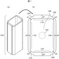
図1は、本発明の反応セルの模式図であり、(a)は俯瞰図を、(b)は反応セル形状の上面模式図を示す。反応セル100は、向かい合う2組の平板110と120、及び130と140、前記平板110と130をつなぐ角部150、前記平板110と140をつなぐ角部160、前記平板120と130をつなぐ角部170、前記平板120と140をつなぐ角部180、底面190とからなる。なお、本図では、平板110、120を短辺側とし、平板130、140を長辺側としている。反応セル100は、底面190の中央裏側にゲート191を有し、一組の平板110、120の肉厚をそれぞれa1、a2とし、平板110、120の両端の角部150〜180のそれぞれの最大肉厚をb1〜b4とした時、次の関係を満たすことを特徴としている。
1A and 1B are schematic views of a reaction cell of the present invention, where FIG. 1A is an overhead view and FIG. 1B is a schematic top view of a reaction cell shape. The
a1>b1、a1>b2、a2>b3、a2>b4
図1(a)に示す反応セル100の俯瞰図の上面開口部より、分析対象となる測定物(例えば、血清成分)を滴下し、反応セル100内に充填する。測定物が充填された反応セル100に光を照射し、図1(b)に示す平板120から110、または110から120へ光を透過させ、透過率を検出することで、測定物の吸光分析を行う。ここで、光が透過する面を光透過部と呼ぶことにする。この光透過部にウェルドが発生していると、透過光の一部に吸収や散乱が生じ、安定した透過性を確保できない。
a1> b1, a1> b2, a2> b3, a2> b4
A measurement object (for example, serum component) to be analyzed is dropped from the top opening of the overhead view of the
そこで、本発明に係る上記形状とすることにより、光透過部でのウェルド発生を防止し、安定した透過性を得ることができる。その理由を従来形状との比較で以下に説明する。 Therefore, by adopting the above-described shape according to the present invention, it is possible to prevent the occurrence of welds in the light transmission portion and to obtain stable transparency. The reason will be described below in comparison with the conventional shape.
ウェルドの発生メカニズム模式図を図2に示す。図2は、金型中に充填中の樹脂の流れ(図中の流れ1、2)を示す。(a)は樹脂の流れの様子を示す俯瞰図であり、(b)は(a)で示す断面1における樹脂が充填された金型の断面を示す。
A schematic diagram of the mechanism of weld generation is shown in FIG. FIG. 2 shows the flow of the resin being filled in the mold (flows 1 and 2 in the figure). (A) is a bird's-eye view which shows the mode of flow of resin, (b) shows the section of a metallic mold filled with resin in
図2(a)で示すように、成形時の樹脂充填において、流速分布は一様でなく、充填の早い部分と遅い部分があり、充填の遅い部分において樹脂の合流が起こる。この合流部においてキャビティ内にあらかじめ存在する空気等の気体が排出されきらないまま樹脂が固化すると、成形品表面にウェルドとなって残る。ここで、「合流角=空気が排出される樹脂未充填部への開口角」であり、合流角が小さいほど空気の逃げ場が少なくなって、排出されづらくなる。よって、合流角が小さいほど、ウェルドが生じる可能性が大きくなる。 As shown in FIG. 2 (a), in resin filling at the time of molding, the flow velocity distribution is not uniform, there are a fast filling portion and a slow filling portion, and the resin merging occurs in the slow filling portion. When the resin solidifies without exhausting gas such as air existing in the cavity in advance at the junction, it remains as a weld on the surface of the molded product. Here, “the merging angle = the opening angle to the resin unfilled portion where air is discharged”, and the smaller the merging angle, the smaller the air escape space becomes, and the more difficult it is to discharge. Therefore, the smaller the merging angle, the greater the possibility of welds.
図3に従来形状を示す。従来の反応セル300は、向かい合う2組の平板310と320、及び330と340、前記平板310と330をつなぐ角部350、前記平板310と340をつなぐ角部360、前記平板320と330をつなぐ角部370、前記平板320と340をつなぐ角部380、底面390とからなり、底面390の中央裏側にゲート391を有する。光透過部である一組の平板310、320のそれぞれの肉厚a1、a2に比べて、その両端の角部350〜380のそれぞれの最大肉厚b1、b2、b3、b4の方が大きかった。
FIG. 3 shows a conventional shape. The
この結果、成形時の樹脂充填においては光透過部よりも角部から先に充填される。その理由は、流動抵抗の小さい部分に優先的に樹脂が流入するためである。流動抵抗は肉厚の3乗に比例し、肉厚が薄いほど大きくなる。このため、角部に比べて肉厚の薄い光透過部の充填速度が遅くなり、光透過部にて樹脂の合流が起きる。 As a result, in the resin filling at the time of molding, the corner is filled before the light transmitting portion. The reason is that the resin preferentially flows into a portion having a small flow resistance. The flow resistance is proportional to the cube of the wall thickness, and increases as the wall thickness decreases. For this reason, the filling speed of the light transmitting portion having a small thickness compared to the corner portion is slowed down, and the resin merges at the light transmitting portion.
これを検証するため、成形シミュレーションソフトウェアを用いて樹脂充填過程を計算した結果を図4に示す。 In order to verify this, the result of calculating the resin filling process using molding simulation software is shown in FIG.
図4(a)は、図3に示す従来の反応セルにおいて、角部の肉厚が光透過部より厚い場合の計算例である。ゲートから流入した樹脂は、肉厚の大きい角部に優先的に流入し、平板部を挟んで2つの角部を進む流れがV字形状を呈しており、合流角は光透過部である短辺側平板部において110度と小さくなっている。また、このため、空気の排出が十分でなかった場合にウェルドとなる可能性が高いことがわかる。長辺側平板部においては、合流角は130度となっている。別途行なった実験との比較により、成形シミュレーションにおける合流角が130度を下回ると、ウェルドが生じることがわかった。 FIG. 4A shows an example of calculation in the case where the thickness of the corner portion is thicker than that of the light transmitting portion in the conventional reaction cell shown in FIG. The resin flowing in from the gate flows preferentially into the corner having a large thickness, and the flow proceeding through the two corners across the flat plate portion has a V shape, and the confluence angle is a short light transmission portion. It is as small as 110 degrees in the side plate portion. For this reason, it can be seen that there is a high possibility of welding when the air is not sufficiently discharged. In the long side flat plate portion, the merging angle is 130 degrees. By comparison with the experiment conducted separately, it was found that when the merging angle in the molding simulation was less than 130 degrees, a weld was generated.
これに対し、図1に示す本発明のセル形状は、角部の肉厚を光透過部よりも薄くしている。この形状により光透過部での流速を早め、同部における樹脂合流を回避することが期待できる。これを三次元のセル形状で検証するため、本発明のセル形状の樹脂充填過程を成形シミュレーションにて計算した結果の例を図4(b)に示す。 On the other hand, the cell shape of the present invention shown in FIG. 1 has a corner portion thinner than the light transmission portion. With this shape, it can be expected that the flow velocity in the light transmission part is increased and the resin confluence in the part is avoided. In order to verify this with a three-dimensional cell shape, FIG. 4B shows an example of a result obtained by calculating the resin filling process of the cell shape of the present invention by molding simulation.
光透過部である短辺側平板部の流速が角部に比べて速くなった結果、短辺側平板部において樹脂合流が見られず、ウェルド発生を防止できる。なお、短辺側角部の肉厚は同じである必要はない。この理由を、反応セルの角部の肉厚と樹脂充填分布の関係を示す図8を用いて説明する。(a)は、角部の肉厚がb1<b2の場合を示し、(b)はb1=b2の場合であり、(c)はb1>b2の場合である。仮に光透過部肉厚に対する2つの角部(例えば、150、160)の肉厚に差があった場合でも、図8(a)または(c)に示すように光透過部内での樹脂合流を回避できる。 As a result of the flow velocity of the short-side flat plate portion, which is the light transmitting portion, being higher than that of the corner portion, resin merging is not seen in the short-side flat plate portion, and the occurrence of welds can be prevented. Note that the thickness of the short side corners need not be the same. The reason for this will be described with reference to FIG. 8 showing the relationship between the thickness of the corner of the reaction cell and the resin filling distribution. (A) shows a case where the thickness of the corner portion is b1 <b2, (b) shows a case where b1 = b2, and (c) shows a case where b1> b2. Even if there is a difference in the thickness of two corners (for example, 150 and 160) with respect to the thickness of the light transmitting portion, the resin merging in the light transmitting portion is performed as shown in FIG. 8 (a) or (c). Can be avoided.
通常、反応セルは透過光の平行性を鑑みて、短辺側の側面は肉厚が一定な平板を用いるが、金型加工精度の限界等により厳密に肉厚一定な平板とすることは難しい。しかし、光透過部内位置による肉厚ばらつきが10μm以内で、かつ角部の肉厚がばらつきを含めた光透過部肉厚よりも薄ければ、本発明は効果がある。 Normally, the reaction cell uses a flat plate with a constant thickness on the side surface on the short side in consideration of the parallelism of the transmitted light, but it is difficult to make a flat plate with a strictly constant thickness due to limitations in mold processing accuracy and the like. . However, the present invention is effective as long as the variation in thickness depending on the position in the light transmitting portion is within 10 μm and the thickness of the corner portion is smaller than the thickness of the light transmitting portion including the variation.
また、透過光の平行性をある程度犠牲にする場合は、必ずしも一定の肉厚にする必要はない。その場合、上述したことから、反応セルの管壁の肉厚の一部に最大値を有し、該最大値を有する位置から短辺側角部に亘って該壁厚が単調減少する形状にすれば、樹脂を金型に流入させるときに合流が生じることはなく、ウェルド発生もない。 Further, when the parallelism of transmitted light is sacrificed to some extent, it is not always necessary to make the wall thickness constant. In that case, from the above, it has a shape that has a maximum value in a part of the wall thickness of the tube wall of the reaction cell, and the wall thickness monotonously decreases from the position having the maximum value to the corner on the short side. In this case, no confluence occurs when the resin flows into the mold, and no weld is generated.
図4(b)の場合、光透過部ではない長辺側における樹脂合流角は100度と小さくなり、ウェルドが発生する。これは角部の肉厚を光透過部平板部に比べて薄くしすぎたためと考えられる。ただし、長辺側は光透過部ではないので、ウェルド発生しても光の透過性に影響はでない。 In the case of FIG. 4B, the resin merging angle on the long side which is not the light transmitting portion is as small as 100 degrees, and a weld is generated. This is thought to be because the thickness of the corner portion was made too thin compared to the flat plate portion of the light transmitting portion. However, since the long side is not a light transmitting portion, the light transmission is not affected even if a weld occurs.
図4(c)について次段落で説明し、(d)に関しては実施例3で説明する。 FIG. 4C will be described in the next paragraph, and (d) will be described in the third embodiment.
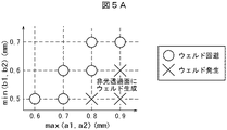
図4(b)の場合、短辺側と長辺側の肉厚差を適切に設定することで、長辺側でのウェルド発生も防止できると考えられる。そこで、セルの寸法形状と樹脂材料、成形条件を変えて計算を行ない、長辺側の樹脂合流角を調べた。その結果得られたウェルド回避可否範囲を図5Aに示す。また、図5Bには、図5Aに示す結果を計算する際の反応セルの形状およびそれに用いたパラメータ一覧を示す。(a)は、反応セルの平面図であり、(b)は計算に用いた形状に関するパラメータ範囲(最小、最大)を示し、(c)は計算における樹脂物性の特性範囲(最小、最大)を示し、(d)は成形条件の範囲(最小、最大)を示している。なお、樹脂の粘度等の物性は、同一樹脂であっても温度やせん断速度によって変化するが、ここでは計算中に取った値の範囲を示している。また、光透過部は必ずしも短辺側である必要はないが、ここでは短辺側を光透過部として扱っている。 In the case of FIG. 4B, it is considered that the occurrence of welds on the long side can be prevented by appropriately setting the thickness difference between the short side and the long side. Therefore, the calculation was performed by changing the dimensional shape of the cell, the resin material, and the molding conditions, and the resin merge angle on the long side was examined. The weld avoidance range obtained as a result is shown in FIG. 5A. FIG. 5B shows the shape of the reaction cell and the parameter list used for calculating the result shown in FIG. 5A. (A) is a plan view of a reaction cell, (b) shows a parameter range (minimum, maximum) regarding the shape used in the calculation, and (c) shows a characteristic range (minimum, maximum) of the resin physical properties in the calculation. (D) shows the range of molding conditions (minimum, maximum). In addition, although physical properties, such as the viscosity of resin, change with temperature and a shear rate, even if it is the same resin, the range of the value taken during calculation is shown here. In addition, the light transmission portion does not necessarily have to be on the short side, but here the short side is treated as the light transmission portion.
図5Aは、横軸に平板310、320の肉厚a1、a2のどちらか大きい値を取り、
縦軸に角部の肉厚b1、b2のどちらか小さい値を取った場合のウェルド発生の有無をプロトした図である。
図5Aより、横軸の値から縦軸の値を減算した値が0.2mm以下、すなわち、max(a1,a2)−min(b1,b2)<0.2の領域において長辺側平板部におけるウェルド発生も防止できることがわかった。ここで、max(a1,a2)は、括弧内の変数の中から最大値を抽出する関数であり、min(b1,b2)は、括弧内の変数の中から最小値を抽出する関数である。図4(c)は同領域での計算結果の例である。
5A, the horizontal axis takes the larger value of the thicknesses a1 and a2 of the
It is the figure which prototyped the presence or absence of the weld generation | occurrence | production when the vertical axis | shaft took the smaller value of the wall thickness b1 of a corner | angular part, or b2.
From FIG. 5A, the long side flat plate portion in the region where the value obtained by subtracting the value on the vertical axis from the value on the horizontal axis is 0.2 mm or less, that is, max (a1, a2) −min (b1, b2) <0.2. It has been found that the occurrence of welds in can also be prevented. Here, max (a1, a2) is a function for extracting the maximum value from the variables in parentheses, and min (b1, b2) is a function for extracting the minimum value from the variables in parentheses. . FIG. 4C shows an example of a calculation result in the same region.
よって、本実施例によれば、光透過部でのウェルド発生を防止し、透過光の散乱を低減し安定した透過性を有する高分析効率の生化学自動分析装置用反応セルを提供することができる。 Therefore, according to the present embodiment, it is possible to provide a reaction cell for an automatic biochemical analyzer with high analytical efficiency that prevents the occurrence of welds in the light transmission part, reduces the scattering of transmitted light, and has stable permeability. it can.
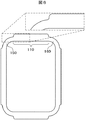
図1に示す反応セルの平板110、120におけるセル肉厚は一定の厚さを保持し、両端部で角ばった形状となっている。
本実施例では、図6のように、セル肉厚がなだらかに変化する形状とすることで、離型抵抗を下げることができ、分析時における気泡の付着・滞留を低減することができる。実験によれば、表面形状に内接する円の半径が0.1mmよりも大きくすることで効果が認められた。
The cell thickness in the
In the present embodiment, as shown in FIG. 6, by adopting a shape in which the cell thickness changes gently, the mold release resistance can be lowered, and the adhesion and retention of bubbles during analysis can be reduced. According to the experiment, the effect was recognized by making the radius of the circle inscribed in the surface shape larger than 0.1 mm.
分析時、血清の温度調節を目的として、セルは温度管理された液体中に浸されるが、測光面に気泡が付着していると測定エラーを誘発する。しかし、本実施例に示す形状とすることで、気泡の付着・滞留を低減できるので、測定エラーの誘発を防止できる効果がある。 At the time of analysis, the cell is immersed in a temperature-controlled liquid for the purpose of temperature control of serum, but if a bubble is attached to the photometric surface, a measurement error is induced. However, by adopting the shape shown in the present embodiment, it is possible to reduce the adhesion / retention of bubbles, and thus it is possible to prevent the measurement error from being induced.
本発明の他の反応セル形状を図7に示す。実施例1との違いは角部の肉厚は従来のままとし、セル底面の光透過部側にスロープを設けた点である。 Another reaction cell shape of the present invention is shown in FIG. The difference from Example 1 is that the thickness of the corners is kept as before, and a slope is provided on the light transmission part side of the cell bottom.
反応セル700は、向かい合う2組の平板710と720、及び730と740、前記平板710と730をつなぐ角部750、前記平板710と740をつなぐ角部760、前記平板720と730をつなぐ角部770、前記平板720と740をつなぐ角部780、底面790とからなり、底面790の中央裏側にゲート791を有する。
The
セル底面からある高さにおける短辺側の肉厚d1およびd2と、同じ高さhにおける長辺側の肉厚e1およびe2が次の関係を満たすセルである。 The thicknesses d1 and d2 on the short side at a certain height from the cell bottom surface and the thicknesses e1 and e2 on the long side at the same height h satisfy the following relationship.
d1>e1、d1>e2、d2>e1、d2>e2
本形状の成形シミュレーションによる樹脂充填過程の計算結果の例を図4(d)に示す。
図4(d)に示すように、短辺側には、合流部は発生していない。
d1> e1, d1> e2, d2> e1, d2> e2
An example of the calculation result of the resin filling process by the molding simulation of this shape is shown in FIG.
As shown in FIG. 4 (d), no joining portion is generated on the short side.
従って、本実施例で示す形状でも光透過部である短辺側平板部において樹脂合流が見られず、ウェルド発生を防止できる。本実施例は実施例1と異なり、ゲートのあるセル底から一定の高さに限って、光透過部における樹脂合流回避の効果があるが、分析時に測光に用いる領域は上記効果の及ぶ範囲内とすることができ、実用上での支障はない。 Therefore, even in the shape shown in the present embodiment, the resin merging is not seen in the short side flat plate portion which is the light transmitting portion, and the occurrence of welds can be prevented. Unlike the first embodiment, the present embodiment has an effect of avoiding the resin merging in the light transmitting portion only at a certain height from the cell bottom where the gate is located. There is no practical problem.
本実施例は、実施例1〜3に示すいずれかの反応セルを用いた吸光分析を自動で行なう生化学自動分析装置に関するものである。 This example relates to a biochemical automatic analyzer that automatically performs absorption analysis using any of the reaction cells shown in Examples 1 to 3.
生化学自動分析装置は、図9Bのように、回転可能なディスク910の周辺部沿って配列された反応セル904へ光を照射する光源901と、反応セルを通過した光を検出する検出部907と、検出部などを制御する制御部913筐(分析装置の筐体内に内蔵されている)と、制御部913へデータを入力する入力部912と、制御部からの出力を表示する表示部911などで構成される。本発明の反応セルを用いる点以外は、本生化学自動分析装置は通常のものと同様の構成である。
As shown in FIG. 9B, the biochemical automatic analyzer includes a
上記反応セルに血清に試薬を混合・反応させた検査液を充填し、その反応セルに可視光を含む100nm〜1000nmの帯域の各波長を有する光を照射し、該光を検査液中を透過させる。透過光の各波長における吸光光度を測定することで、血清内に存在する糖質やタンパク質、ミネラル等の各成分の含有量を推定する。 The reaction cell is filled with a test solution in which a reagent is mixed and reacted with serum, and the reaction cell is irradiated with light having each wavelength of 100 nm to 1000 nm including visible light, and the light is transmitted through the test solution. Let By measuring the absorbance at each wavelength of the transmitted light, the content of each component such as carbohydrate, protein, and mineral present in the serum is estimated.
上述した各実施例による反応セルは、少なくとも光透過部には、ウェルドの発生がない。 In the reaction cell according to each of the above-described embodiments, no weld is generated at least in the light transmission portion.
従って、測光において光の散乱が起こって分析効率が落ちることはなく、また測定エラーを生じることもないので、分析精度の高い、安定した透過性を有する反応セルを搭載した生化学自動分析装置を提供することができる。 Therefore, since light scattering does not occur in photometry and analysis efficiency does not decrease, and measurement errors do not occur, a biochemical automatic analyzer equipped with a reaction cell with high analytical accuracy and stable permeability is installed. Can be provided.
また本発明の構成は光透過部のみならず、光透過面の広域にわたって、そして光透過面全域にわたり実現されている。これがより好ましいことは言うまでもない。 Moreover, the structure of this invention is implement | achieved not only in the light transmissive part but in the wide area of a light transmissive surface, and the whole light transmissive surface. Needless to say, this is more preferable.
100,300,700…反応セル、
110,120,130,140,310,320,330,340,710,720,730,740…セル平板部、
150,160,170,180,350,360,370,380,750,760,770,780…セル角部、
190,390,790…セル底面
191,391,791…ゲート、
901…光源、902…スリット、903…平行光(測光光線)、904…反応セル、905…回折格子、906…分光スペクトル、907…検出部、
910…ディスク、911…表示部、912…入力部、913…制御部。
100, 300, 700 ... reaction cell,
110, 120, 130, 140, 310, 320, 330, 340, 710, 720, 730, 740 ... cell flat plate portion,
150,160,170,180,350,360,370,380,750,760,770,780 ... cell corner,
190, 390, 790 ... cell
901 ... Light source, 902 ... Slit, 903 ... Parallel light (photometric light beam), 904 ... Reaction cell, 905 ... Diffraction grating, 906 ... Spectral spectrum, 907 ... Detector,
910: Disc, 911 ... Display unit, 912 ... Input unit, 913 ... Control unit.
Claims (8)
前記反応セルの管壁は、向かい合う一組の壁面と、前記一組の壁面のそれぞれと角部を介して連接する2つの側壁面と、を有し、
前記一組の壁面の壁厚は、前記角部厚よりも厚く、前記壁面の全体に亘って一様な厚さ、もしくはそれぞれの壁厚の一部に最大値を有する場合は、該最大値を有する位置から前記角部に亘って該壁厚が単調減少することを特徴とする反応セル。 A bottomed reaction cell molded with optical resin or optical glass and having an opening at one end,
The tube wall of the reaction cell has a pair of wall surfaces facing each other, and two side wall surfaces connected to each of the pair of wall surfaces through corners,
The wall thickness of the set of wall surfaces is thicker than the corner thickness, and is uniform over the entire wall surface, or has a maximum value in a part of each wall thickness. A reaction cell characterized in that the wall thickness monotonously decreases from a position having a point to the corner.
一組の平板の肉厚をそれぞれa1、a2とし、前記肉厚a1を有する平板の両端につながる角部の最大肉厚をそれぞれb1、b2とし、前記肉厚a2を有する平板の両端につながる角部の最大肉厚をそれぞれb3、b4とした場合、次の関係を満たすことを特徴とする反応セル。
a1>b1、a1>b2、a2>b3、a2>b4 A reaction cell formed of an optical resin or optical glass and comprising two sets of flat plates facing each other, a corner portion connecting the flat plates, and a bottom portion,
The thicknesses of a pair of flat plates are a1 and a2, respectively, the maximum thicknesses of the corners connected to both ends of the flat plate having the thickness a1 are b1 and b2, respectively, and the corners connected to both ends of the flat plate having the thickness a2 A reaction cell characterized by satisfying the following relationship when the maximum thickness of the part is b3 and b4, respectively.
a1> b1, a1> b2, a2> b3, a2> b4
max(a1,a2)−min(b1,b2)<0.2mm The reaction cell according to claim 2, wherein the a1, a2, and the b1, b2, b3, b4 satisfy the following relationship.
max (a1, a2) -min (b1, b2) <0.2 mm
前記外周表面が、前記接続部において曲率半径rの形状を有し、r>0.1mmを満たしながら前記角部と接続されることを特徴とする請求項2に記載の反応セル。 There is a step on the outer peripheral surface of the connecting portion between the flat plate and the corner connecting the flat plate,
The reaction cell according to claim 2, wherein the outer peripheral surface has a shape with a radius of curvature r at the connection portion and is connected to the corner portion while satisfying r> 0.1 mm.
前記底面部と前記向かい合う2組の平板との接続部において、前記2組の平板は前記底面部から前記開口部に向けて肉厚が次第に変化するテーパ形状を有し、
前記底面部の上端面から高さhの仮想線と交差する前記平板の一組の肉厚をd1、d2とし、前記高さhにおけるもう一組の平板の肉厚をe1、e2とした時、次の関係を満たすことを特徴とする反応セル。
d1>e1、d1>e2、d2>e1、d2>e2 A reaction cell molded from an optical resin or optical glass, comprising a pair of flat plates facing each other, a corner portion connecting the flat plates, and a bottom portion, and having an opening at one end,
In connection portion between the two pairs of flat plate facing the said bottom portion, said two pairs of flat plates have a tapered wall thickness changes gradually toward the opening from the bottom surface portion,
When the thickness of one set of the flat plates intersecting the imaginary line of height h from the upper end surface of the bottom portion is d1, d2, and the thickness of another set of flat plates at the height h is e1, e2. A reaction cell characterized by satisfying the following relationship:
d1> e1, d1> e2, d2> e1, d2> e2
Priority Applications (5)
| Application Number | Priority Date | Filing Date | Title |
|---|---|---|---|
| JP2014031886A JP6208596B2 (en) | 2014-02-21 | 2014-02-21 | Reaction cell and biochemical automatic analyzer |
| CN201580005932.8A CN106062532A (en) | 2014-02-21 | 2015-02-10 | Reaction cell and biochemical automated analyzer |
| EP15752273.1A EP3109617B1 (en) | 2014-02-21 | 2015-02-10 | Reaction cell and biochemical automated analyzer |
| PCT/JP2015/053608 WO2015125663A1 (en) | 2014-02-21 | 2015-02-10 | Reaction cell and biochemical automated analyzer |
| US15/115,049 US20160354776A1 (en) | 2014-02-21 | 2015-02-10 | Reaction Cell and Automatic Biochemical Analyzer |
Applications Claiming Priority (1)
| Application Number | Priority Date | Filing Date | Title |
|---|---|---|---|
| JP2014031886A JP6208596B2 (en) | 2014-02-21 | 2014-02-21 | Reaction cell and biochemical automatic analyzer |
Publications (3)
| Publication Number | Publication Date |
|---|---|
| JP2015158374A JP2015158374A (en) | 2015-09-03 |
| JP2015158374A5 JP2015158374A5 (en) | 2016-12-01 |
| JP6208596B2 true JP6208596B2 (en) | 2017-10-04 |
Family
ID=53878169
Family Applications (1)
| Application Number | Title | Priority Date | Filing Date |
|---|---|---|---|
| JP2014031886A Active JP6208596B2 (en) | 2014-02-21 | 2014-02-21 | Reaction cell and biochemical automatic analyzer |
Country Status (5)
| Country | Link |
|---|---|
| US (1) | US20160354776A1 (en) |
| EP (1) | EP3109617B1 (en) |
| JP (1) | JP6208596B2 (en) |
| CN (1) | CN106062532A (en) |
| WO (1) | WO2015125663A1 (en) |
Families Citing this family (1)
| Publication number | Priority date | Publication date | Assignee | Title |
|---|---|---|---|---|
| JP6838612B2 (en) * | 2017-02-15 | 2021-03-03 | コニカミノルタ株式会社 | Inspection chip and inspection system |
Family Cites Families (23)
| Publication number | Priority date | Publication date | Assignee | Title |
|---|---|---|---|---|
| DE2702189C2 (en) * | 1977-01-20 | 1985-05-30 | Philips Patentverwaltung Gmbh, 2000 Hamburg | Cell for flameless atomic absorption spectroscopy |
| JPS53157787U (en) * | 1977-05-18 | 1978-12-11 | ||
| JPS60166843A (en) * | 1984-02-09 | 1985-08-30 | Optic:Kk | Glass cell for liquid analyzer and preparation thereof |
| JPS61247376A (en) * | 1985-04-26 | 1986-11-04 | Hitachi Ltd | Automated analyzer |
| DE69012887D1 (en) * | 1989-06-20 | 1994-11-03 | Claudio Bonini | Test tubes with a lenticular outer surface, especially for automatic clinical analyzes. |
| CA2067425C (en) * | 1991-05-07 | 1996-09-24 | Alfons Balmer | Cuvette for optical measurements |
| DE4223840C2 (en) * | 1992-07-20 | 1994-06-16 | Zeiss Carl Jena Gmbh | Refractometer |
| US6387030B1 (en) * | 2000-06-30 | 2002-05-14 | Beckman Coulter, Inc. | Internal adapter with a pellet well for a centrifuge container |
| JP4689907B2 (en) * | 2001-09-28 | 2011-06-01 | 富士フイルム株式会社 | Measuring chip and manufacturing method thereof |
| US7300055B2 (en) * | 2003-04-17 | 2007-11-27 | Kyocera Mita Corporation | Image forming apparatus |
| US7138091B2 (en) * | 2003-07-18 | 2006-11-21 | Dade Behring Inc. | Reaction cuvette having anti-wicking features for use in an automatic clinical analyzer |
| CA2603209A1 (en) * | 2005-04-01 | 2006-10-12 | Mitsubishi Kagaku Iatron, Inc. | Biosample multiple autoanalyzer, method of autoanalysis and reaction cuvette |
| JP2006349582A (en) * | 2005-06-17 | 2006-12-28 | Olympus Corp | Agitating container and chemical analysis apparatus using the same |
| ES2633619T3 (en) * | 2005-07-27 | 2017-09-22 | Sysmex Corporation | Bucket |
| JP2008096115A (en) * | 2006-10-05 | 2008-04-24 | Sysmex Corp | Cuvette |
| CN201156031Y (en) * | 2008-02-02 | 2008-11-26 | 施慧勇 | Cuvette of biochemical analyzer |
| WO2011125418A1 (en) * | 2010-04-09 | 2011-10-13 | 日本電気株式会社 | Web-content conversion device, web-content conversion method, and recording medium |
| EP2466291B1 (en) * | 2010-12-15 | 2013-09-11 | F. Hoffmann-La Roche AG | Cuvette for photometric measurement of small liquid volumes |
| US20120196271A1 (en) * | 2011-01-27 | 2012-08-02 | Pocared Diagnostics Ltd. | Iris Control System for Conducting the Identification of Bacteria in Biological Samples |
| JP2013076622A (en) * | 2011-09-30 | 2013-04-25 | Hitachi High-Tech Manufacturing & Service Corp | Cell series structure for analysis device |
| CN202994646U (en) * | 2012-12-27 | 2013-06-12 | 深圳雷杜生命科学股份有限公司 | Reaction cup conveniently clamped and transferred by mechanical arm |
| CN105593124B (en) * | 2013-09-30 | 2018-05-22 | 福莱克国际有限公司 | With the fluid container assembly for strengthening angle post |
| US10099822B2 (en) * | 2013-09-30 | 2018-10-16 | Flextank International Limited | Closure assembly |
-
2014
- 2014-02-21 JP JP2014031886A patent/JP6208596B2/en active Active
-
2015
- 2015-02-10 CN CN201580005932.8A patent/CN106062532A/en active Pending
- 2015-02-10 US US15/115,049 patent/US20160354776A1/en not_active Abandoned
- 2015-02-10 EP EP15752273.1A patent/EP3109617B1/en active Active
- 2015-02-10 WO PCT/JP2015/053608 patent/WO2015125663A1/en active Application Filing
Also Published As
| Publication number | Publication date |
|---|---|
| CN106062532A (en) | 2016-10-26 |
| EP3109617A1 (en) | 2016-12-28 |
| US20160354776A1 (en) | 2016-12-08 |
| EP3109617B1 (en) | 2022-10-19 |
| EP3109617A4 (en) | 2017-10-04 |
| JP2015158374A (en) | 2015-09-03 |
| WO2015125663A1 (en) | 2015-08-27 |
Similar Documents
| Publication | Publication Date | Title |
|---|---|---|
| JP5350810B2 (en) | Automatic analyzer and automatic analysis method | |
| US8994940B2 (en) | Fine particle measurement apparatus and optical axis calibration method | |
| CN103261876B (en) | Automatic analysing apparatus | |
| US8976353B2 (en) | Multiwell plate lid for improved optical measurements | |
| JP4895109B2 (en) | Shape inspection method and shape inspection apparatus | |
| ITUD20090047A1 (en) | EQUIPMENT FOR ANALYZING A BIOLOGICAL SAMPLE | |
| JP2011107032A (en) | Surface plasmon resonance chip | |
| JP4308231B2 (en) | In-plane detection by photometry | |
| JP7381561B2 (en) | Method for manufacturing microfluidic rotor devices | |
| US11628452B2 (en) | Microfluidic rotor device | |
| JP6208596B2 (en) | Reaction cell and biochemical automatic analyzer | |
| CN104833620A (en) | Atmospheric particulate matter concentration monitoring device | |
| JPWO2009057659A1 (en) | Sample analysis method and apparatus | |
| US7889337B2 (en) | Optical method for determination of the total suspended solids in jet fuel | |
| US3701620A (en) | Sample scattering cell for a photometer | |
| CN102128809B (en) | Surface plasma resonance sensor chip assembly and cylindrical prism chip | |
| CN105092426A (en) | Measuring method for nanoparticle 90-degree scattering spectrum | |
| TW202020429A (en) | Systems and methods for inspecting a microfluidic rotor device | |
| US20230010477A1 (en) | Cavity for gas measurements | |
| JP2008070245A (en) | Flow cell for fluid sample | |
| JP7097175B2 (en) | A cell for measuring particle physical properties and a particle physical property measuring device using the cell. | |
| WO2017221495A1 (en) | Liquid film forming nozzle | |
| EP3484686B1 (en) | Sample vessel having opaque and translucent portions, and sample analyzer system with such a sample vessel | |
| CN105327722A (en) | Container for liquid analysis | |
| CN109855726A (en) | A kind of calibrating installation and method of the light source power of Immune scatter turbidimetry |
Legal Events
| Date | Code | Title | Description |
|---|---|---|---|
| RD02 | Notification of acceptance of power of attorney |
Free format text: JAPANESE INTERMEDIATE CODE: A7422 Effective date: 20150803 |
|
| A521 | Request for written amendment filed |
Free format text: JAPANESE INTERMEDIATE CODE: A821 Effective date: 20150803 |
|
| A521 | Request for written amendment filed |
Free format text: JAPANESE INTERMEDIATE CODE: A523 Effective date: 20161013 |
|
| A621 | Written request for application examination |
Free format text: JAPANESE INTERMEDIATE CODE: A621 Effective date: 20161013 |
|
| A131 | Notification of reasons for refusal |
Free format text: JAPANESE INTERMEDIATE CODE: A131 Effective date: 20170606 |
|
| A521 | Request for written amendment filed |
Free format text: JAPANESE INTERMEDIATE CODE: A523 Effective date: 20170728 |
|
| TRDD | Decision of grant or rejection written | ||
| A01 | Written decision to grant a patent or to grant a registration (utility model) |
Free format text: JAPANESE INTERMEDIATE CODE: A01 Effective date: 20170822 |
|
| A61 | First payment of annual fees (during grant procedure) |
Free format text: JAPANESE INTERMEDIATE CODE: A61 Effective date: 20170907 |
|
| R150 | Certificate of patent or registration of utility model |
Ref document number: 6208596 Country of ref document: JP Free format text: JAPANESE INTERMEDIATE CODE: R150 |
|
| S531 | Written request for registration of change of domicile |
Free format text: JAPANESE INTERMEDIATE CODE: R313531 |
|
| S533 | Written request for registration of change of name |
Free format text: JAPANESE INTERMEDIATE CODE: R313533 |
|
| R350 | Written notification of registration of transfer |
Free format text: JAPANESE INTERMEDIATE CODE: R350 |
|
| S111 | Request for change of ownership or part of ownership |
Free format text: JAPANESE INTERMEDIATE CODE: R313117 |
|
| R350 | Written notification of registration of transfer |
Free format text: JAPANESE INTERMEDIATE CODE: R350 |