JP6208569B2 - Gas supply device and air or nitrogen supply device of nuclear power plant - Google Patents
Gas supply device and air or nitrogen supply device of nuclear power plant Download PDFInfo
- Publication number
- JP6208569B2 JP6208569B2 JP2013259680A JP2013259680A JP6208569B2 JP 6208569 B2 JP6208569 B2 JP 6208569B2 JP 2013259680 A JP2013259680 A JP 2013259680A JP 2013259680 A JP2013259680 A JP 2013259680A JP 6208569 B2 JP6208569 B2 JP 6208569B2
- Authority
- JP
- Japan
- Prior art keywords
- valve
- air
- gas
- nitrogen
- gas supply
- Prior art date
- Legal status (The legal status is an assumption and is not a legal conclusion. Google has not performed a legal analysis and makes no representation as to the accuracy of the status listed.)
- Active
Links
Images


Classifications
-
- Y—GENERAL TAGGING OF NEW TECHNOLOGICAL DEVELOPMENTS; GENERAL TAGGING OF CROSS-SECTIONAL TECHNOLOGIES SPANNING OVER SEVERAL SECTIONS OF THE IPC; TECHNICAL SUBJECTS COVERED BY FORMER USPC CROSS-REFERENCE ART COLLECTIONS [XRACs] AND DIGESTS
- Y02—TECHNOLOGIES OR APPLICATIONS FOR MITIGATION OR ADAPTATION AGAINST CLIMATE CHANGE
- Y02E—REDUCTION OF GREENHOUSE GAS [GHG] EMISSIONS, RELATED TO ENERGY GENERATION, TRANSMISSION OR DISTRIBUTION
- Y02E30/00—Energy generation of nuclear origin
Description
本発明は気体供給装置及び原子力プラントの空気又は窒素供給装置に係り、例えば、原子力プラントに設置されている空気作動弁の如く、弁の開閉動作を切替るために配管系の途中に電磁弁が設置されているものに好適な気体供給装置及び原子力プラントの空気又は窒素供給装置に関するものである。 The present invention relates to a gas supply device and an air or nitrogen supply device of a nuclear power plant. For example, an electromagnetic valve is provided in the middle of a piping system in order to switch the opening / closing operation of a valve, such as an air operated valve installed in a nuclear power plant. The present invention relates to a gas supply device suitable for an installed one and an air or nitrogen supply device of a nuclear power plant.
原子力発電所を含む各種プラントには、空気、窒素又は蒸気等の気体や、水等の液体を流すための配管が設置されており、この配管の途中には、配管内の流体を流すための開動作、遮断するための閉動作、或いは電気信号や空気圧信号によって、電気又は圧縮空気・窒素等を用いて作動することで、流量、圧力等を調整する電動弁、空気又は窒素作動弁が設置されている。 In various plants including nuclear power plants, pipes for flowing gases such as air, nitrogen or steam, and liquids such as water are installed. Electric valve or air or nitrogen operation valve is installed to adjust the flow rate, pressure, etc. by operating with electricity or compressed air / nitrogen etc. by open operation, closing operation to shut off, or electric signal or pneumatic signal Has been.
特に、原子力プラントに設置されている空気又は窒素作動弁においては、弁の開閉動作を切替るために空気配管系の途中に電磁弁が設けられているが、例えば、全電源喪失事故(SBO:Station Blackout)時には、電磁弁のコイル無励磁化、空気供給源からの空気圧の低下によってフェイル動作するものの、その後は、電源からの電気の供給不能、空気供給装置からの空気の供給不能により、空気作動弁の動作が不能になり、その後の空気又は窒素作動弁の運用に支障が生じる恐れがある。 In particular, in an air or nitrogen operating valve installed in a nuclear power plant, an electromagnetic valve is provided in the middle of an air piping system in order to switch the opening / closing operation of the valve. For example, a total power loss accident (SBO: At the time of Station Blackout), the solenoid valve's coil is de-excited and the air pressure decreases from the air supply source. However, after that, the air supply cannot be supplied and the air supply device cannot supply the air. There is a possibility that the operation of the operation valve becomes impossible, and the subsequent operation of the air or nitrogen operation valve may be hindered.
このように空気作動弁には、電源からの電気の供給不能、空気供給装置からの空気の供給不能による空気作動弁操作不能ポテンシャルがあるため、非常時(例えば、SBO時)においても、安全に遠隔操作できることは勿論、通常時(電源が確保されている正常運転時或いは正常待機時)には誤動作(意図しない動作)しない設備が求められている。 As described above, the air-operated valve has the potential of being unable to operate the air-operated valve due to the inability to supply electricity from the power source and the inability to supply air from the air supply device. Therefore, even in an emergency (for example, SBO) Needless to say that remote control is possible, there is a need for equipment that does not malfunction (unintentional operation) during normal operation (during normal operation or normal standby with a power supply secured).
一方、全電源喪失が生じ、原子炉圧力容器内で発生した水素が原子炉建屋内に漏洩した場合でも、水素を安全に処理して水素爆発を防ぎ、原子炉建屋の損壊を防止する技術が特許文献1に記載されている。
On the other hand, even if the total power loss occurs and hydrogen generated in the reactor pressure vessel leaks into the reactor building, there is a technology that safely treats hydrogen to prevent hydrogen explosion and damage the reactor building. It is described in
通常、空気又は窒素作動弁の開閉動作は、その弁の動力となる空気又は窒素を供給する空気配管系の途中に設置されている電磁弁の電源をオン、オフすることで切り替えられるが、電源喪失時には、電源喪失、動力用空気源の喪失により、空気又は窒素作動弁の開閉動作のための電磁弁の電源のオン、オフができなくなると共に、動力となる空気又は窒素の供給も不可能となり、外部からの遠隔操作が不可能になる。 Normally, the opening or closing operation of an air or nitrogen operating valve can be switched by turning on and off the power of an electromagnetic valve installed in the middle of an air piping system that supplies air or nitrogen to power the valve. At the time of loss, the power supply of the solenoid valve for the opening / closing operation of the air or nitrogen operating valve cannot be turned on / off due to the loss of the power supply or the power source, and the supply of power air or nitrogen becomes impossible. Remote operation from the outside becomes impossible.
しかし、設計基準となった不具合を上回るような事故事象においては、必要な空気又は窒素作動弁は、通常の電源・動力用空気源とは異なる電源・動力用空気源による外部からの遠隔操作を、空気又は窒素作動弁の通常の作動特性に影響を及ぼさずに、可能とすることが必要となる。 However, in the event of an accident that exceeds the design standard failure, the necessary air or nitrogen actuated valve must be remotely operated from the outside by a power source / power air source different from the normal power source / power air source. It is necessary to be able to do this without affecting the normal operating characteristics of the air or nitrogen operated valve.
特に、原子力発電所においては、SBOのような非常時に、原子炉格納容器内の空気又は窒素作動弁を開閉可能とするためには、原子炉格納容器の外部に操作用の電磁弁を設置し、通常電源とは別のバッテリーなどの電源を接続して、空気又は窒素作動弁の開閉動作を行うには、空気又は窒素作動弁に要求される作動時間等の作動特性に影響を及ぼさないようにすることや、操作用空気の原子炉格納容器外への排気などの考慮が必要であり、これらのことを考慮した電源喪失時に用いられる空気又は窒素供給装置の操作源の確保が必要となっている。 In particular, in a nuclear power plant, in order to be able to open and close the air or nitrogen operation valve in the reactor containment vessel in an emergency such as SBO, an operation electromagnetic valve is installed outside the reactor containment vessel. In order to open and close the air or nitrogen operating valve by connecting a power source such as a battery other than the normal power source, the operating characteristics such as the operating time required for the air or nitrogen operating valve will not be affected. In addition, it is necessary to consider the exhaust of the operating air to the outside of the containment vessel, and it is necessary to secure the operating source of the air or nitrogen supply device used at the time of power loss considering these things ing.
しかしながら、上述した特許文献1には、全電源喪失時に、原子炉圧力容器内で発生した水素が原子炉建屋内に漏洩した場合でも、原子炉建屋の損壊を防止する手段については記載されているが、電源喪失時に用いられる空気又は窒素供給装置の操作原確保については勿論、通常時における意図しない動作(誤動作)を防止することについては、全く記載されていない。
However,
本発明は上述の点に鑑みなされたもので、その目的とするところは、電源喪失時においても空気作動弁等の作動弁を遠隔操作できることは勿論、遠隔操作者が安全に操作できる気体供給装置及び原子力プラントの空気又は窒素供給装置を提供することにある。 The present invention has been made in view of the above points, and its object is to provide a gas supply device that can be operated safely by a remote operator as well as remotely operating valves such as an air operated valve even when power is lost. And providing an air or nitrogen supply device for a nuclear power plant.
本発明の気体供給装置は、上記目的を達成するために、プラントにおける少なくとも気体を流すための配管の途中に設置され、該配管内を流れる気体により弁本体を動作させる作動弁と、前記配管の途中に設置され、前記作動弁への気体の流れの開閉を行う第1の電磁弁と、該第1の電磁弁に気体を供給する第1及び第2の気体供給源と、前記第1の電磁弁の排気ラインに設置され、前記第1の電磁弁からの排気と該第1の電磁弁への給気を切替えると共に、電源喪失時には前記第1の電磁弁に気体を供給するために前記第2の気体供給源との接続に切替えられる第1の切替弁と、該第1の切替弁の前記第2の気体供給源側の配管の途中に設置され、前記第1の切替弁の給気側へのリークを防止する隔離弁とを備え、前記隔離弁は、前記第1の電磁弁が動作不能の際に、通常運転時の電源とは異なる第2の電源によって動作して開にされ、前記第1の切替弁に前記第2の気体供給源から気体を供給する第2の電磁弁を備えていることを特徴とする。 In order to achieve the above object, the gas supply device of the present invention is installed in the middle of a pipe for flowing gas at least in a plant, and operates a valve main body with the gas flowing in the pipe. A first solenoid valve installed on the way to open and close the flow of gas to the working valve; first and second gas supply sources for supplying gas to the first solenoid valve; and the first solenoid valve The exhaust valve is installed in an exhaust line of the solenoid valve to switch between exhaust from the first solenoid valve and supply air to the first solenoid valve, and to supply gas to the first solenoid valve when power is lost A first switching valve that is switched to a connection with the second gas supply source, and a pipe on the second gas supply source side of the first switching valve; An isolation valve for preventing leakage to the air side, and the isolation valve includes the first When the solenoid valve is inoperable, a second power source that is operated and opened by a second power source that is different from the power source during normal operation and supplies gas from the second gas supply source to the first switching valve The electromagnetic valve is provided.
また、本発明の原子力プラントの空気又は窒素供給装置は、上記目的を達成するために、原子炉格納容器に収納されている原子炉圧力容器からの蒸気をタービン建屋に供給する主蒸気配管から分岐した配管の途中に設けられ、原子炉の圧力が一定値以上になった際に開動作して前記主蒸気配管内の主蒸気を逃す主蒸気逃し安全弁若しくは原子炉圧力容器が収納されている原子炉格納容器からの気体を排気塔から放出する非常用ガス処理系に設置されている配管の途中に開閉弁が設けられ、前記原子炉格納容器の圧力が一定値以上になった際に前記開閉弁を開動作させて前記原子炉格納容器内の気体を前記非常用ガス処理系から排気する空気又は窒素作動弁と、前記主蒸気逃し安全弁を開動作させるためのシリンダ若しくは前記空気又は窒素作動弁を開動作させるために、前記開閉弁に駆動力を供給するシリンダと、該シリンダへの空気又は窒素の流れの開閉を行う第1の電磁弁と、該第1の電磁弁に空気又は窒素を供給する第1及び第2の空気又は窒素供給源と、前記第1の電磁弁の排気ラインに設置され、前記第1の電磁弁からの排気と該第1の電磁弁への給気を切替えると共に、電源喪失時には前記第1の電磁弁に空気又は窒素を供給するために前記第2の空気又は窒素供給源との接続に切替えられる第1の切替弁と、該第1の切替弁の前記第2の空気又は窒素供給源側の配管の途中に設置され、前記第1の切替弁の給気側へのリークを防止する隔離弁とを備え、前記隔離弁は、前記第1の電磁弁が動作不能の際に、通常運転時の電源とは異なる第2の電源によって動作して開にされ、前記第1の切替弁に前記第2の空気又は窒素供給源から空気又は窒素を供給する第2の電磁弁を備えていることを特徴とする。 In order to achieve the above object, the air or nitrogen supply device for a nuclear power plant according to the present invention branches from a main steam pipe for supplying steam from a reactor pressure vessel stored in a reactor containment vessel to a turbine building. The main steam escape safety valve or the reactor pressure vessel that stores the main steam in the main steam pipe and opens when the pressure of the reactor reaches a certain value or more is provided. An on-off valve is provided in the middle of a pipe installed in the emergency gas processing system that discharges gas from the reactor containment vessel from the exhaust tower, and the opening and closing is performed when the pressure in the reactor containment vessel exceeds a certain value. An air or nitrogen operating valve for opening the valve to exhaust the gas in the reactor containment vessel from the emergency gas processing system, and a cylinder for opening the main steam relief valve or the air or nitrogen operating valve In order to open the valve, a cylinder that supplies driving force to the on-off valve, a first electromagnetic valve that opens and closes a flow of air or nitrogen to the cylinder, and air or nitrogen in the first electromagnetic valve Are installed in the exhaust line of the first solenoid valve, and the exhaust from the first solenoid valve and the supply of air to the first solenoid valve. A first switching valve that is switched to connection with the second air or nitrogen supply source to supply air or nitrogen to the first solenoid valve when power is lost, and An isolation valve installed in the middle of the piping on the second air or nitrogen supply source side to prevent leakage of the first switching valve to the supply side, and the isolation valve includes the first electromagnetic valve When the valve is inoperable, it is operated and opened by a second power supply different from the power supply during normal operation. Is characterized in that it comprises a second electromagnetic valve for supplying air or nitrogen from the second air or nitrogen supply source to the first switching valve.
更に、本発明の原子力プラントの空気又は窒素供給装置は、上記目的を達成するために、原子炉圧力容器に配管によって接続され、前記原子炉圧力容器の圧力、水位を保持する加圧器に設置され、必要に応じて前記加圧器の圧力を強制的に減圧する加圧器逃し弁及び原子炉圧力容器に配管によって接続され、前記原子炉圧力容器に冷却水を供給する蒸気発生器内の蒸気を逃す主蒸気逃し弁と、前記加圧器逃し弁を開動作させるために、内部に蓄えられている空気又は窒素を前記加圧器逃し弁に供給するシリンダ及び前記主蒸気逃し弁を開動作させるために、内部に蓄えられている空気又は窒素を前記主蒸気逃し弁に供給するシリンダと、それぞれの前記配管の途中に設置され、前記加圧器逃し弁に供給するシリンダ及び前記主蒸気逃し弁に供給するシリンダへの空気又は窒素の流れの開閉を行うそれぞれの第1の電磁弁と、該それぞれの第1の電磁弁に空気又は窒素を供給するそれぞれの第1及び第2の空気又は窒素供給源と、前記それぞれの第1の電磁弁の排気ラインに設置され、前記それぞれの第1の電磁弁からの排気と該それぞれの第1の電磁弁への給気を切替えると共に、電源喪失時には前記それぞれの第1の電磁弁に空気又は窒素を供給するために前記それぞれの第2の空気又は窒素供給源との接続に切替えられるそれぞれの第1の切替弁と、該それぞれの第1の切替弁の前記それぞれの第2の空気又は窒素供給源側の配管の途中に設置され、前記それぞれの第1の切替弁の給気側へのリークを防止するそれぞれの隔離弁とを備え、前記それぞれの隔離弁は、前記それぞれの第1の電磁弁が動作不能の際に、通常運転時の電源とは異なるそれぞれの第2の電源によって動作して開にされ、前記それぞれの第1の切替弁に前記それぞれの第2の空気又は窒素供給源から空気又は窒素を供給するそれぞれの第2の電磁弁を備えていることを特徴とする。
Further, in order to achieve the above object, the air or nitrogen supply device of the nuclear power plant of the present invention is connected to a reactor pressure vessel by piping, and is installed in a pressurizer that holds the pressure and water level of the reactor pressure vessel. The steam in the steam generator for supplying cooling water to the reactor pressure vessel is released by connecting to the reactor pressure vessel and a pressurizer relief valve for forcibly reducing the pressure of the pressurizer as necessary. In order to open the main steam relief valve, the cylinder for supplying air or nitrogen stored therein to the pressurizer relief valve and the main steam relief valve to open the pressurizer relief valve, A cylinder that supplies air or nitrogen stored therein to the main steam relief valve, a cylinder that is installed in the middle of each of the pipes, and that supplies the pressurizer relief valve and the main steam relief valve Each first solenoid valve for opening and closing a flow of air or nitrogen to the cylinder to be operated, and each first and second air or nitrogen source for supplying air or nitrogen to each first solenoid valve And an exhaust line of each of the first solenoid valves for switching exhaust from the respective first solenoid valves and supply of air to the respective first solenoid valves, and at the time of power loss, A first switching valve that is switched to a connection with the respective second air or nitrogen source to supply air or nitrogen to the first solenoid valve, and Each isolation valve installed in the middle of the piping of each of the second air or nitrogen supply side and preventing leakage to the supply side of each of the first switching valves. The valve When the first solenoid valve is inoperable, the first solenoid valve is operated and opened by each second power source different from the power source during normal operation. Each of the second solenoid valves for supplying air or nitrogen from an air or nitrogen supply source is provided.
本発明によれば、電源喪失時においても空気作動弁等の作動弁を遠隔操作できることは勿論、遠隔操作者が安全に操作できる効果がある。 According to the present invention, an operation valve such as an air operation valve can be remotely operated even when the power supply is lost, and there is an effect that a remote operator can operate safely.
以下、図示した実施例に基づいて本発明の気体供給装置及び原子力プラントの空気又は窒素供給装置を説明する。なお、各図において、弁の黒表示は“閉”状態を、白表示は“開”状態をそれぞれ示すものである。また、符号は、同一構成部品には同符号を使用すると共に、既に説明した部品の説明は省略する。 Hereinafter, based on the illustrated embodiment, the gas supply device of the present invention and the air or nitrogen supply device of a nuclear power plant will be described. In each figure, the black display of the valve indicates the “closed” state, and the white display indicates the “open” state. Further, the same reference numerals are used for the same component parts, and the description of the parts already described is omitted.
図1乃至図5は、本発明の気体供給装置の実施例1を示し、例えば、弁本体(図示せず)を開閉する空気作動弁アクチュエータ1があり、この空気作動弁アクチュエータ1は、建屋21内の配管20A1の途中に設置された第1の電磁弁2Aにより動作されものである。即ち、第1の電磁弁2Aは、第1の電源のオン、オフにより、供給口であるIA系(第1の気体供給源である計装空気供給系統設備)から制御用空気又は窒素が供給されることで、空気作動弁アクチュエータ1が作動し、作動完了後、第1の電磁弁2Aの第1の電源のオフにより、空気作動弁アクチュエータ1の制御用空気又は窒素は、第1の電磁弁2Aの排気口から後述する第1の切替弁3AのA→Eの経路で排出され、空気作動弁アクチュエータ1は作動前の状態に復帰する。
FIGS. 1 to 5
また、本実施例では、建屋21内の第1の切替弁3Aと建屋21外に設置されている空気又は窒素を供給する空気又は窒素供給源(第2の気体供給源)であるボンベ4Aとの間の配管20B1には、後述する第3の電磁弁5A及び隔離弁6が配置されている。
In the present embodiment, the
また、本実施例では、第1の電磁弁2Aが動作不能の際に、通常運転時の第1の電源とは異なる第2の電源によって動作して隔離弁6を開にし、第1の切替弁3Aに第2の気体供給源であるボンベ4Aから気体を供給する第2の電磁弁2Bを備え、この第2の電磁弁2Bが設置されている配管20A2の延長線上には、第2の切替弁3B及び第3の気体供給源であるボンベ4Bからの気体の流れの開閉を行う第4の電磁弁5Bが設置され、第2の電源が喪失した際には、第4の電磁弁5Bを開にして第3の気体供給源であるボンベ4Bから気体を供給し、第2の切替弁3Bが排気から給気に切り替わることで、第2の電磁弁2Bを操作して隔離弁6を開操作するものである。
Further, in this embodiment, when the first
即ち、上述した隔離弁6は、第1の電磁弁2Aが電源喪失などにより動作不能の場合、第2の電源によって第2の電磁弁2Bの電源をオンに操作し、隔離弁6を開にすることで、第1の切替弁3Aに第2の気体供給源であるボンベ4Aから気体を供給することを可能とする(図2及び図3参照)。しかし、第2の電磁弁2Bを操作する第2の電源も喪失した場合には、第4の電磁弁5Bを開操作して気体を供給し、第2の切替弁3Bが排気側から給気に切り替わることで、第2の電磁弁2Bを経由して隔離弁6のエアシリンダに、第3の気体供給源であるボンベ4Bから空気を供給することが可能となる。これにより、隔離弁6が開操作され、建屋21外に設置されている空気又は窒素が貯蔵されている第2の気体供給源であるボンベ4Aから第3の電磁弁5Aを介して、制御用空気又は窒素が隔離弁6を経由して第1の切替弁3Aに給気できる(図4及び図5参照)。
That is, when the first
これにより、第1の切替弁3AにP⇔Aの流路が形成され(図3及び図5参照)、ボンベ4Aから第3の電磁弁5A、隔離弁6、第1の切替弁3A、第1の電磁弁2Aを経由して空気作動弁アクチュエータ1へ至る制御用空気又は窒素の流路が確保されて空気作動弁アクチュエータ1が作動する。空気作動弁アクチュエータ1の作動完了後は、第3の電磁弁5Aの電源がオフすると、第3の電磁弁5A、隔離弁6、第1の切替弁3A、第1の電磁弁2A、空気作動弁アクチュエータ1間の圧力が低下し、第1の切替弁3Aの流路がA→Eに切り替わる(図1参照)。更に、空気作動弁アクチュエータ1の制御用空気又は窒素は、第1の電磁弁2Aの排気口から第1の切替弁3AのA→Eの経路で排出され、空気作動弁アクチュエータ1は作動前の状態に復帰する。
Thereby, a flow path of P⇔A is formed in the
つまり、本実施例では、第1の電磁弁2Aには、気体(空気又は窒素)を供給する気体供給源として、第1の気体供給源であるIA系(計装空気供給系統設備)と第2の気体供給源であるボンベ4Aの2系列を備えている。
In other words, in the present embodiment, the first
本実施例では、このようにして、空気作動弁アクチュエータ1を動作し、弁本体を開閉させるようになっている。
In this embodiment, the air operated
なお、図1乃至図5では、第1の切替弁3Aの表記は、空気油圧回路図のJISシンボル表記を模したものとしている。
In FIG. 1 to FIG. 5, the notation of the
上述したように、本実施例では、第1の電磁弁2Aとボンベ4A間の建屋21内の配管20A1の途中に、第1の電磁弁2Aからの排気と、この第1の電磁弁2Aへの給気を切替える第1の切替弁3Aが設置されているが、この第1の切替弁3Aは、電源喪失時には、第1の電磁弁2Aに空気又は窒素を供給するためにボンベ4Aとの接続に切替えられるものである。
As described above, in this embodiment, the exhaust from the first
つまり、第1の電磁弁2Aの排気ライン11A側の建屋21内にある配管20A1の途中に第1の切替弁3Aを設置し、第1の切替弁3Aに作動用の空気又は窒素が、建屋21外に設けられたボンベ4Aから配管20B1を介して供給されると、通常時は、図1に示す如く、第1の電磁弁2Aの排気ライン11A側に接続されている第1の切替弁3Aが、図3に示すように、給気側に切り替わり、作動用空気又は窒素を第1の電磁弁2Aに供給することができ、電源喪失時においても、空気作動弁アクチュエータ1に空気の供給が可能となる。
That is, the
また、上述した隔離弁6は、第1の切替弁3Aのボンベ4A側の建屋21外の配管20B1の途中に設置され、通常時の建屋21内の雰囲気が、第1の切替弁3Aの給気側のリークによって建屋21外へ漏出するのを防止するものである。
Further, the
更に、上述した如く、第2の電磁弁2Bの排気ライン11B側にある配管20A2の途中には第2の切替弁3Bが設置され、この第2の切替弁3Bに作動用の空気又は窒素が、建屋21外に設けられたボンベ4Bから配管20B2を介して供給されると隔離弁6が開になり、通常時は、図1に示す如く、第1の電磁弁2Aの排気ライン11A側に接続されている第1の切替弁3Aが、図5に示すように、給気側に切り替わり、ボンベ4Aから作動用空気又は窒素を第1の電磁弁2Aに供給することができ、電源喪失時においても、空気作動弁アクチュエータ1に空気の供給が可能となる。
Further, as described above, the
なお、第1の切替弁3Aに空気又は窒素を供給する設備は、建屋21内の電源とは別の電源種別、例えばバッテリーを持つことで、安全性を高めることができるが、更なるバックアップとして、手動弁によって給気しても良い。
The facility for supplying air or nitrogen to the
即ち、本実施例では、ボンベ4Aから第1の切替弁3Aに供給する建屋21外の配管20B1に設置されている第3の電磁弁5A及びボンベ4Bから第2の切替弁3Bに供給する建屋21外の配管20B2に設置されている第4の電磁弁5Bは、交流電源又は直流電源、直流電源、手動のそれぞれを動力源とする3つの電磁弁から構成されている。つまり、図1乃至図5に示す如く、第3の電磁弁5A1及び第4の電磁弁5B1は、非常時(その1)の際に、交流電源又は直流電源を動力源とし、第3の電磁弁5A2及び第4の電磁弁5B2は、非常時(その2)の際に、直流電源(例えば、バッテリー)を動力源として動作するものであり、また、第3の電磁弁5A3及び第4の電磁弁5B3は、バックアップとして手動で動作するものである。
That is, in the present embodiment, the third
そして、電源喪失時には、直流電源(バッテリー)を駆動原とする第3の電磁弁5A2又は第4の電磁弁5B2を駆動し、ボンベ4A又は4Bから第1の電磁弁2A又は第2の電磁弁2Bに空気又は窒素を供給するものである。第1の切替弁3Aの給気側へのリークは、隔離弁6により防止されている。
When the power source is lost, the third solenoid valve 5A2 or the fourth solenoid valve 5B2 having a DC power source (battery) as a driving source is driven, and the
次に、上述した実施例1の気体供給装置における各状態の具体的な例を、図6乃至図15を用いて説明する。 Next, specific examples of each state in the gas supply device of the first embodiment will be described with reference to FIGS.
図6乃至図15には、弁本体7として、空気又は窒素を動力源とするリンクを伴う駆動装置であるシリンダ8を有するアングル弁(スプリング力により、空気又は窒素が供給されていない場合は、閉状態)を示し、第1の切替弁3Aの表記は、空気油圧回路図のJISシンボル表記ではなく、他の弁の表記同様に、白・黒で開閉状態を表記している。
6 to 15, an angle valve having a
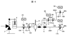
図6及び図9は、本実施例の気体供給装置の通常使用時の待機状態を示す。 6 and 9 show a standby state during normal use of the gas supply device of this embodiment.
該図に示す如く、通常使用時は、待機状態において、シリンダ(空気作動弁アクチュエータ)8に接続する第1の電磁弁2Aは、排気ライン11A側が開になっている。また、第1の切替弁3Aは排気ライン13A側が開になっている。
As shown in the figure, during normal use, the first
図7及び図16は、本実施例の気体供給装置の通常使用時の給気時の状態及びフローを示す。 FIG.7 and FIG.16 shows the state and flow at the time of the air supply at the time of normal use of the gas supply apparatus of a present Example.
該図に示す如く、弁作動の信号が第1の電磁弁2Aに入る(ステップ1)と、第1の電磁弁2Aは排気ライン11A側を閉にして給気ライン10A側を開にする(ステップ2)。すると、第1の電磁弁2Aの給気ライン10Aから圧縮空気や圧縮窒素などの気体がシリンダ8に供給され(ステップ3)、弁本体7が作動する(ステップ4)。
As shown in the figure, when a valve operation signal enters the first
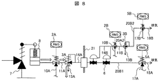
図8及び図17は、本実施例の気体供給装置の通常使用時の排気時の状態およびフローを示す。 8 and 17 show the state and flow during exhaust during normal use of the gas supply device of this embodiment.
該図に示す如く、待機状態に復帰するときは、第1の電磁弁2Aに信号を送り(ステップ5)、第1の電磁弁2Aの排気ライン11A側を開にし、給気ライン10A側を閉にする(ステップ6)。すると、シリンダ8に供給された気体は、第1の電磁弁2Aの排気ライン11A側から排気され(ステップ7)、第1の電磁弁2Aの排気ライン11A側から排気され気体は、第1の切替弁3Aの排気ライン13A(図1乃至図5の第1の切替弁3Aの接続口Eに接続)側から排気される(ステップ8)。シリンダ8を作動させるのに十分な気体がなくなると、弁本体7を作動させ(ステップ9)、待機状態に戻る。一例として、待機時を閉、作動時を開としたが、その逆の作動も可能である。
As shown in the figure, when returning to the standby state, a signal is sent to the
図9は、本実施例の第1の電磁弁2Aの電源喪失などの過酷事故時の待機状態を示す。
FIG. 9 shows a standby state at the time of a severe accident such as loss of power supply of the first
該図に示す如く、全電源喪失などの過酷事故時には、電源喪失により、第1の電磁弁2Aは排気ライン11A側を開にした状態になり、外部からの操作が不可能なまま待機する。
As shown in the figure, at the time of a severe accident such as the loss of all power, the first
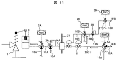
図10、図11及び図18は、本実施例の第1の電磁弁2Aの電源喪失などの過酷事故時の給気時の状態及びフローを示す。
10, FIG. 11 and FIG. 18 show the state and flow at the time of air supply during a severe accident such as loss of power supply of the first
該図に示す如く、電源喪失により第1の電磁弁2Aは、排気ライン11A(図1乃至図5の第1の切替弁3Aの接続口Aに接続)側を開にし、給気ライン10A側を閉の状況にする(ステップ10)。外部からシリンダ8を作動させるために、建屋21外にあるバッテリーなどを駆動原とする第3の電磁弁5Aの給気ライン17A側を開にし、排気ライン18A側を閉にする(ステップ11)。
As shown in the figure, due to the loss of power, the first
次に、同様に第2の電磁弁2Bに信号を送り、給気側ライン10B側を開の状況にし、排気ライン11B(図1乃至図5の第2の切替弁3Bの接続口Aに接続)側を閉にする(ステップ12)ことにより、供給された気体は、隔離弁6のシリンダを操作して開にする(ステップ13)。
Next, similarly, a signal is sent to the second
第1の切替弁3Aを作動させるに十分な気体を、第3の電磁弁5Aの給気ライン17A(図1乃至図5の第1の切替弁3Aの接続口Pに接続)側から供給する(ステップ14)。供給された気体によって、第1の切替弁3Aは排気ライン13A(図1乃至図5の第1の切替弁3の接続口E)側を閉にして給気ライン14A(図1乃至図5の第1の切替弁3Aの接続口P)を開とする。すると、建屋21外から給気された気体は、第1の切替弁3Aの給気ライン14A(図1乃至図5の第1の切替弁3Aの接続口Pに接続)から第1の電磁弁2Aの排気ライン11A(図1乃至図5の第1の切替弁3Aの接続口Aに接続)を通りシリンダ8へと到達し、シリンダ8に弁本体7を作動させるに十分な気圧が充填されることで、弁本体7が作動する(ステップ15)。
Gas sufficient to operate the
図12及び図19は、本実施例の第1の電磁弁2Aの電源喪失などの過酷事故時の排気時の状態及びフローを示す。
FIGS. 12 and 19 show the state and flow during exhaust during a severe accident such as a loss of power to the
該図に示す如く、建屋21外にあるバッテリーを駆動原とする第3の電磁弁5Aに弁作動の信号を送る(ステップ16)。弁本体7を待機状態に戻す場合は、建屋21外の第3の電磁弁5Aの排気ライン18A側を開にし、給気ライン17A側を閉にする(ステップ17)。すると、シリンダ8に供給された気体は、第1の電磁弁2Aの排気ライン11A側から排気され(ステップ18)、第1の電磁弁2Aの排気ライン11A(図1乃至図5の第1の切替弁3Aの接続口Aに接続)から排気された気体は、第1の切替弁3Aの給気ライン14A(図1乃至5の第1の切替弁3Aの接続口Pに接続)、建屋21外の第3の電磁弁5Aの排気ライン18Aを経由し、排気される(ステップ19)。第1の切替弁3Aを作動させるのに十分な気体がなくなると、第1の切替弁3Aは、給気ライン14A(図1乃至図5の第1の切替弁3Aの接続口Pに接続)側を閉にし、排気ライン13A(図1乃至図5の第1の切替弁3Aの接続口Eに接続)側を開にする(ステップ20)。すると、シリンダ8に残っている気体は、第1の電磁弁2Aの排気ライン11A側から排気され、第1の切替弁3Aの排気ライン13A(図1乃至図5の第1の切替弁3Aの接続口Eに接続)から建屋21内に排気される(ステップ21)。シリンダ8を作動させるのに十分な気体がなくなると、弁本体7を作動させ(ステップ22)待機状態に戻る。一例として、待機時を閉、作動時を開としたが、その逆の作動も可能となる。
As shown in the figure, a valve operation signal is sent to the third
図9は、本実施例の気体供給装置の全電源喪失などの過酷事故時の待機状態を示す。 FIG. 9 shows a standby state at the time of a severe accident such as loss of all power sources of the gas supply device of this embodiment.
該図に示す如く、全電源喪失などの過酷事故時には、電源喪失により、第1の電磁弁2Aは排気ライン11A側を開にした状態になり、外部からの操作が不可能なまま待機する。同様に、第2の電磁弁2Bは、排気ライン11B側を開にした状態になり、外部からの操作が不可能なまま待機する
図13、図14及び図20は、本実施例の気体供給装置の過酷事故時の給気時の状態及びフローを示す。
As shown in the figure, at the time of a severe accident such as the loss of all power, the first
該図に示す如く、電源喪失により第1の電磁弁2Aは、排気ライン11A(図1乃至図5の第1の切替弁3Aの接続口Aに接続)側を開にし、給気ライン10A側を閉の状況にする(ステップ23)。同様に、電源喪失により第2の電磁弁2Bは、給気ライン10B(図1乃至図5の第1の切替弁3Aの接続口Pに接続)側を閉にし、排気ライン11B側を開の状況にする(ステップ24)。外部から弁本体7を作動させるために、建屋21外にあるバッテリーなどを駆動原とする第3の電磁弁5Aの給気ライン17A側を開にし、排気ライン18A側を閉にする(ステップ25)。
As shown in the figure, due to the loss of power, the first
次に、バッテリーなどの第1の電磁弁1Aの電源とは別の電源を駆動原とする第4の電磁弁5Bの給気ライン17B側を開にし、排気ライン18B側を閉にすることで、第2の切替弁3Bを作動させるに十分な気体を第4の電磁弁5Bの給気ライン17B(図1乃至図5の第1の切替弁3Aの接続口Pに接続)側から供給する(ステップ26)。供給された気体によって、第2の切替弁3Bは、排気ライン13B(図1乃至図5の第1の切替弁3Aの接続口E)側を閉にして、給気ライン14B(図1乃至図5の第1の切替弁3Aの接続口P)を開とする(ステップ27)。すると、給気された気体は、第2の切替弁3Bの給気ライン14B(図1乃至図5の第1の切替弁3Aの接続口Pに接続)から第2の電磁弁2Bの排気ライン11B(図1乃至図5の第1の切替弁3Aの接続口Aに接続)を通り、隔離弁6のシリンダを操作して開にする(ステップ28)ことで、第1の切替弁3Aを作動させるに十分な気体を第3の電磁弁5Aの給気ライン17A(図1乃至図5の第1の切替弁3Aの接続口Pに接続)側から供給する(ステップ29)。供給された気体によって、第1の切替弁3Aは、排気ライン13A(図1乃至図5の第1の切替弁3Aの接続口E)側を閉にして、給気ライン14A(図1乃至図5の第1の切替弁3Aの接続口P)側を開とする。すると、建屋21外から給気された気体は、第1の切替弁3Aの給気ライン14A(図1乃至図5の第1の切替弁3Aの接続口Pに接続)側から第1の電磁弁2Aの排気ライン11A(図1乃至図5の第1の切替弁3Aの接続口Aに接続)を通りシリンダ8へと到達し、シリンダ8に弁本体7を作動させるに十分な気圧が充填されることで、弁本体7が作動する(ステップ30)。
Next, by opening the
図15及び図21は、本実施例の気体供給装置の過酷事故時の排気時の状態及びフローを示す。 FIG.15 and FIG.21 shows the state and flow at the time of exhaust at the time of a severe accident of the gas supply apparatus of a present Example.
該図に示す如く、建屋21外にあるバッテリーを駆動原とする第3の電磁弁5Aに弁作動の信号を送る(ステップ31)。弁本体7を待機状態に戻す場合は、建屋21外の第3の電磁弁5Aの排気ライン18A側を開にし、給気ライン17A側を閉にする(ステップ32)。すると、シリンダ8に供給された気体は、第1の電磁弁2Aの排気ライン11A側から排気され(ステップ33)、第1の電磁弁2Aの排気ライン11A(図1乃至図5の第1の切替弁3Aの接続口Aに接続)から排気された気体は、第1の切替弁3Aの給気ライン14A(図1乃至図5の第1の切替弁3Aの接続口Pに接続)側から、建屋21外の第3の電磁弁5Aの排気ライン18Aを経由し、排気される(ステップ34)。第1の切替弁3Aを作動させるのに十分な気体がなくなると、第1の切替弁3Aは、給気ライン14A(図1乃至図5の第1の切替弁3Aの接続口Pに接続)側を閉にし、排気ライン13A側(図1乃至図5の第1の切替弁3Aの接続口Eに接続)を開にする(ステップ35)。すると、シリンダ8に残っている気体は、第1の電磁弁2Aの排気ライン11A側から排気され、第1の切替弁3Aの排気ライン13A(図1乃至図5の第1の切替弁3Aの接続口Eに接続)から建屋21内に排気される(ステップ36)。シリンダ8を作動させるのに十分な気体がなくなると、弁本体7を作動させ(ステップ37)。
As shown in the figure, a valve operation signal is sent to the third
次に、バッテリーなどの第1の電磁弁2Aの電源とは別の電源を駆動原とする第4の電磁弁5Bの給気ライン17B側を閉にし、排気ライン18B側を開にする(ステップ38)ことで、第2の切替弁3Bを作動させるに十分な気体がなくなると、第2の切替弁3Bは給気ライン14B(図1乃至図5の第1の切替弁3Aの接続口E)側を閉にして、排気ライン13B(図1乃至図5の第1の切替弁3Aの接続口P)を開とする(ステップ39)。すると、隔離弁6のシリンダに給気された気体は、第2の電磁弁2Bの排気ライン11B(図1乃至図5の第1の切替弁3Aの接続口Aに接続)から第2の切替弁3Bの排気ライン11B(図1乃至図5の第1の切替弁3Aの接続口Pに接続)を通り排気され(ステップ40)、隔離弁6を作動させて閉にさせ(ステップ41)待機状態に戻る。一例として、待機時を閉、作動時を開としたが、その逆の作動も可能となる。
Next, the
このように本実施例では、第1の電磁弁2Aの排気ライン11A側の配管20A1の途中に第1の切替弁3Aを接続し、電源喪失時に建屋21外からボンベ4Aなどで空気又は窒素等の気体を供給していると共に、隔離弁6は、第1の電磁弁2Aが電源喪失などにより動作不能の場合、第2の電源によって第2の電磁弁2Bの電源をオンに操作し、隔離弁6を開にすることで、第1の切替弁3Aにボンベ4Aから気体を供給することが可能となる。
As described above, in the present embodiment, the
更に、第2の電磁弁2Bの第2の電源も喪失した場合には、第4の電磁弁5Bを開操作してボンベ4Bから気体を第2の切替弁3Bに供給し、第2の切替弁3Bが排気側から給気側に切り替わることで、第2の電磁弁2Bを経由して隔離弁6のエアシリンダに空気が供給され、隔離弁6を開操作することが可能とし、隔離弁6が開操作されると、建屋21外に設置されている空気又は窒素が貯蔵されている第2の気体供給源であるボンベ4Aから第3の電磁弁5Aを介して、制御用空気又は窒素を隔離弁6を経由して第1の切替弁3Aに給気できるため、第1の切替弁3Aに作動用の空気又は窒素が供給されると、通常時は排気側に接続されている第1の切替弁3Aが給気側に切り替わり、電源喪失時に空気又は窒素を第1の電磁弁2Aに供給することが可能となる。
Further, when the second power source of the second
また、第1の切替弁3Aが切り替わる圧力は、建屋21内の圧力よりも十分高くなっており、第1の切替弁3Aが作動中は、第3の電磁弁5Aを経由して、建屋21内の雰囲気が建屋21外に流出することはない。
Further, the pressure at which the
従って、電源喪失時においても空気作動弁等の作動弁を遠隔操作でき、かつ、隔離弁6の制御用の第2の電源の電源喪失時にも隔離弁6を操作でき、空気作動弁アクチュエータ1に気体を送ることができる効果がある。また、第2の電磁弁2B、第3の電磁弁5A又は第4の電磁弁5Bの電源種別(交流電源若しくは直流電源)を、常時使用する第1の電磁弁2Aと差別化することにより、駆動原を多様化できる効果もある。
Therefore, even when the power supply is lost, the operation valve such as the air operation valve can be remotely operated, and also when the power supply of the second power source for controlling the
なお、第1の切替弁3A又は第2の切替弁3Bに空気又は窒素を供給する設備は、建屋21内の電源とは別の電源(例えば、バッテリー)を持つことで安全性を高めることができるが、更なるバックアップとして、手動弁によって給気しても良い。
Note that the facility for supplying air or nitrogen to the
このような本実施例の構成とすることにより、電源喪失時においても空気作動弁等の作動弁を遠隔操作できることは勿論、遠隔操作者が安全に操作できる効果がある。 By adopting such a configuration of the present embodiment, it is possible to remotely operate an operation valve such as an air operation valve even when the power is lost, and an effect that a remote operator can operate safely.
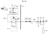
図22に、本発明の気体供給装置の実施例2を示す。該図に示す本実施例では、建屋21内の第1の切替弁3Aと建屋21外に設置されている隔離弁6との間の建屋21内の配管には、通常時には排気ライン10C側を開にし、第1の切替弁3A側を閉にすると共に、電源喪失時には第1の切替弁3A側を開にし、排気ライン10C側を閉にする第5の電磁弁2Cを設置したものである。他の構成は、実施例1と同様である。
FIG. 22 shows a second embodiment of the gas supply device of the present invention. In the present embodiment shown in the figure, the pipe in the
このような本実施例の構成とすることにより、実施例1と同様な効果が得られることは勿論、通常時における意図しない動作(誤動作)を防止できる効果がある。 By adopting such a configuration of the present embodiment, the same effects as in the first embodiment can be obtained, and there is an effect that an unintended operation (malfunction) can be prevented in a normal time.
図23に、本発明の実施例3である原子力プラントの空気又は窒素供給装置を示す。
FIG. 23 shows an air or nitrogen supply device of a nuclear power plant that is
該図に示す如く、本実施例の原子力プラントの空気又は窒素供給装置は、原子炉格納容器48に収納されている原子炉圧力容器40からの蒸気をタービン建屋(図示せず)に供給する主蒸気配管41から分岐した配管51に設けられ、原子炉の圧力が一定値以上になった際に開動作して主蒸気配管41内の主蒸気を逃す主蒸気逃し安全弁43と、この主蒸気逃し安全弁43を強制的に開動作させるために、空気又は窒素を主蒸気逃し安全弁43に駆動力を供給する強制作動用シリンダ47と、強制作動用シリンダ47への空気又は窒素の流れの開閉を行う第1の電磁弁2Aと、この第1の電磁弁2Aの給気口及び排気口に配管を介して独立に空気又は窒素を供給し、原子炉格納容器48外に設置されている第1及び第2の空気又は窒素供給源(特に図示しないが、高圧ガスアキュムレータや実施例1と同様なボンベ4Aや液体窒素を気化させて窒素ガスを供給する)とを備えて概略構成されている。
As shown in the figure, the air or nitrogen supply device of the nuclear power plant of the present embodiment mainly supplies steam from the
そして、本実施例では、原子炉格納容器48内の第1の電磁弁2Aの排気ライン11Aに、第1の電磁弁2Aからの排気と第1の電磁弁2Aへの給気を切替える第1の切替弁3Aが設置され、この第1の切替弁3Aは、電源喪失時には、第1の電磁弁2Aに空気又は窒素を供給するために、隔離弁6を介して原子炉格納容器48外に設置されている第2の空気又は窒素供給源(特に図示せず、ボンベ4Aなど)に、第3の電磁弁5Aの給気ライン17Aを介しての接続に切替えられるようにしたものである。
In the present embodiment, the first
更に、上述した隔離弁6は、第1の電磁弁2Aが動作不能の際に、通常運転時の電源とは異なる第2の電源によって動作して隔離弁6を開にし、第1の切替弁3Aに第2の空気又は窒素供給源(ボンベ4A)から空気又は窒素を供給する第2の電磁弁2Bを備えており、また、第2の空気又は窒素供給源(ボンベ4A)は、隔離弁6が設置されている配管20B1の延長線上に設置されている第3の電磁弁5Aで第2の空気又は窒素供給源(ボンベ4A)の流れの開閉が行われ、かつ、第2の電磁弁2Bが設置されている配管20A2、20B2の延長線上には、第2の切替弁3B及び第3の空気又は窒素供給源(ボンベ4B)からの気体の流れの開閉を行う第4の電磁弁5Bが設置され、第2の電源が喪失した際には、第4の電磁弁5Bを開にして第3の空気又は窒素供給源(ボンベ4B)から空気又は窒素を供給し、第2の切替弁3Bが排気から給気に切り替わることで、第2の電磁弁2Bを操作して隔離弁6が開操作される。
Furthermore, when the
即ち、通常時は第2の電源を用いて第2の気体供給源(ボンベ4A)からの給気で作動するが、第2の電源が喪失した時は、第2の切替弁3Bに、第3の気体供給源(ボンベ4B)の給気ライン17Bに繋がる第4の電磁弁5Bより気体を供給することで、第2の切替弁3Bを第2の電磁弁2Bの排気ライン11B側に切り替えて、隔離弁6に気体を供給することができ、隔離弁6を開閉することができるようになっている。隔離弁6が開操作されると、建屋21外に設置されている空気又は窒素が貯蔵されている第2の気体供給源(ボンベ4A)から第3の電磁弁5Aを介して、制御用空気又は窒素が隔離弁6を経由して第1の切替弁3Aに給気できる(図4及び図5参照)。
That is, normally, the second power source is used to operate by supplying air from the second gas supply source (
これにより、第1の切替弁3AにP⇔Aの流路が形成され(図3及び図5参照)、ボンベ4Aから第3の電磁弁5A、隔離弁6、第1の切替弁3A、第1の電磁弁2Aを経由して強制作動用シリンダ47へ至る制御用空気又は窒素の流路が確保されて主蒸気逃し安全弁43が作動する。
Thereby, a flow path of P⇔A is formed in the
上述した第2及び第3の空気又は窒素供給源(ボンベ4A及び4B)は、実施例1と同様に、原子炉格納容器48外の配管20B1及び20A2に設置されている第3の電磁弁5A及び第4の電磁弁5Bを介して接続され、第3の電磁弁5A及び第4の電磁弁5Bは、交流電源又は直流電源、直流電源(例えば、バッテリー)、手動のそれぞれを動力源とする3つの弁の内から、単独または複数で構成され、その動作は、実施例1と同様である。
The second and third air or nitrogen supply sources (
更に、上述した如く、第1の切替弁3Aの給気側へのリークを防止する隔離弁6は、第1の切替弁3Aのボンベ4A側の原子炉格納容器48外の配管20B1の途中に設置され、第1の切替弁3Aの給気側へのリークを防止する構成としている。
Further, as described above, the
本実施例において、通常、原子炉圧力容器40からは、蒸気が主蒸気配管41を通ってタービン建屋に供給されるが、原子力発電所は地震などの災害を検知すると、配管破断による冷却材喪失事象(LOCA:Loss Of Coolant Accident)を防ぐために、主蒸気配管41に設けられている主蒸気隔離弁42が閉止する。その際、原子炉内の温度は、核燃料の崩壊熱により上昇を続け、原子炉内の圧力も蒸気の発生に伴い上昇する。原子炉の圧力が一定値以上になった場合、主蒸気配管41から分岐した配管51に設けられた主蒸気逃し安全弁43が作動し、原子炉の圧力を低下させる。その際、第1の切替弁3Aは、主蒸気逃し安全弁43の作動に影響を及ぼすことはない。
In this embodiment, normally, steam is supplied from the
原子炉の冷却は、高圧炉心注水系44や低圧炉心注水系45で行われるが、全電源喪失(SBO)時には、外部注水ライン46から非常用ポンプ車などによる注水も可能としておくことが望まれる。
The reactor is cooled by the high-pressure core
この際、原子炉内の圧力が注水の圧力よりも高い場合、原子炉内の圧力を下げる必要があるが、前述の主蒸気逃し安全弁43の安全弁機能は、原子炉内が一定の圧力になるまで作動しないため、主蒸気逃し安全弁43の逃し弁機能を用いて強制的に主蒸気逃し安全弁43を開作動させる必要がある。
At this time, if the pressure in the reactor is higher than the water injection pressure, it is necessary to lower the pressure in the reactor. However, the safety valve function of the main steam
ここで、主蒸気逃し安全弁43の逃し弁機能とは、アキュムレータに蓄えられた窒素や圧縮空気などの気体を、主蒸気逃し安全弁43の強制作動用シリンダ47に供給し、主蒸気逃し安全弁43を開作動させる機能である。
Here, the relief valve function of the main steam
本実施例では、全電源喪失などの過酷事故時は、主蒸気逃し安全弁43に圧縮空気又は圧縮窒素を供給するための第1の電磁弁2Aも操作不能となり、排気側を開にした状態で待機し、その後、第1の電磁弁2Aの排気ライン11A側に第1の切替弁3Aを接続し、隔離弁6を介して作動用の空気又は窒素が、原子炉格納容器48外に設けられたボンベ4Aなどの空気又は窒素供給源から供給し、通常時は排気側に接続されている第1の切替弁3Aを給気側に切り替え、作動用の空気又は窒素を第1の電磁弁2Aに供給することで、電源喪失時においても主蒸気逃し安全弁43を作動させる強制作動用シリンダ47に空気又は窒素が供給されて作動させることが可能となっている。
In this embodiment, in the event of a severe accident such as the loss of all power, the
更に、上述した隔離弁6は、第1の電磁弁2Aが電源喪失などにより動作不能の場合、第2の電源によって第2の電磁弁2Bの電源をオンに操作し、隔離弁6を開にすることで、第1の切替弁3Aに第2の気体供給源であるボンベ4Aから気体を供給することを可能としている。しかし、第2の電源も喪失した場合には、第4の電磁弁5Bを開操作して気体を供給し、第2の切替弁3Bが排気側から給気に切り替わることで、第2の電磁弁2Bを経由して隔離弁6のエアシリンダに空気を供給することが可能となっている。
Further, when the
これにより、隔離弁6を開操作することが可能となり、建屋21外に設置されている空気又は窒素が貯蔵されている第2の気体供給源であるボンベ4Aから第3の電磁弁5Aを介して、制御用空気又は窒素が隔離弁6を経由して第1の切替弁3Aに給気でき、通常時は排気側に接続されている第1の切替弁3Aを給気側に切り替え、作動用の空気又は窒素を第1の電磁弁2Aに供給することで、第1及び第2の電源喪失時においても主蒸気逃し安全弁43を作動させる強制作動用シリンダ47に、空気又は窒素が供給されて作動させることが可能となる。
Thereby, it becomes possible to open the
このように、電源喪失時にも主蒸気逃し安全弁43を作動させることができ、原子炉圧力容器40の圧力は、サプレッションチェンバの接続ラインに逃されて減圧され、原子炉圧力容器40が減圧されることで、外部注水ライン46からの注水が可能となり、原子炉を冷温停止させることが可能となる。
Thus, the main steam
図24に、本発明の実施例4である原子力プラントの空気又は窒素供給装置を示す。
FIG. 24 shows an air or nitrogen supply device of a nuclear power plant that is
該図に示す如く、本実施例の原子力プラントの空気又は窒素供給装置は、原子炉圧力容器40が収納されている原子炉格納容器48からの気体を排気塔54から放出する非常用ガス処理系(非常用ガス処理設備やフィルタベント設備)53に設置されている開閉弁52を駆動する駆動部(シリンダ等)に駆動力を供給する空気又は窒素作動弁50に接続し、この空気又は窒素作動弁50の駆動部(シリンダ等)への空気又は窒素の流れの供給・停止のために開閉を行う第1の電磁弁2Aと、この第1の電磁弁2Aの給気口及び排気口に配管を介して独立に空気又は窒素を供給し、原子炉格納容器48外に設置されている第1及び第2の空気又は窒素供給源(特に図示しないが、実施例1と同様なボンベ4Aや液体窒素を気化させて窒素ガスを供給する)とを備えて概略構成されている。
As shown in the figure, the air or nitrogen supply device of the nuclear power plant of the present embodiment is an emergency gas processing system for releasing the gas from the
そして、本実施例では、第1の電磁弁2Aからの排気ライン11Aに第1の電磁弁2Aへの給気を切替える第1の切替弁3Aが設置され、この第1の切替弁3Aは、電源喪失時には、第1の電磁弁2Aに空気又は窒素を供給するために、隔離弁6を介して原子炉建屋58外に設置されている空気又は窒素供給源(ボンベ4A)に、第3の電磁弁5Aの給気ライン17Aを介しての接続に切替えられるようにしたものである。
In this embodiment, the
更に、上述した隔離弁6は、第1の電磁弁2Aが動作不能の際に、通常運転時の電源とは異なる第2の電源によって動作して隔離弁6を開にし、第1の切替弁3Aに第2の空気又は窒素供給源(ボンベ4A)から空気又は窒素を供給する第2の電磁弁2Bを備えており、また、第2の空気又は窒素供給源(ボンベ4A)は、隔離弁6が設置されている配管20B1の延長線上に設置されている第3の電磁弁5Aで第2の空気又は窒素供給源(ボンベ4A)の流れの開閉が行われ、かつ、第2の電磁弁2Bが設置されている配管20A2、20B2の延長線上には、第2の切替弁3B及び第3の空気又は窒素供給源(ボンベ4B)からの気体の流れの開閉を行う第4の電磁弁5Bが設置され、第2の電源が喪失した際には、第4の電磁弁5Bを開にして第3の空気又は窒素供給源(ボンベ4B)から空気又は窒素を供給し、第2の切替弁3Bが排気から給気に切り替わることで、第2の電磁弁2Bを操作して隔離弁6が開操作される。
Furthermore, when the
即ち、通常時は第2の電源を用いて第2の気体供給源(ボンベ4A)からの給気で作動するが、第2の電源が喪失した時は、第2の切替弁3Bに、第3の気体供給源(ボンベ4B)の給気ライン17Bに繋がる第4の電磁弁5Bより気体を供給することで、第2の切替弁3Bを第3の電磁弁2Bの排気ライン11B側に切り替えて、隔離弁6に気体を供給することができ、隔離弁6を開閉することができるようになっている。隔離弁6が開操作されると、建屋21外に設置されている空気又は窒素が貯蔵されている第2の気体供給源(ボンベ4A)から第3の電磁弁5Aを介して、制御用空気又は窒素が隔離弁6を経由して第1の切替弁3Aに給気できる(図4及び図5参照)。
That is, normally, the second power source is used to operate by supplying air from the second gas supply source (
これにより、第1の切替弁3AにP⇔Aの流路が形成され(図3及び図5参照)、ボンベ4Aから第3の電磁弁5A、隔離弁6、第1の切替弁3A、第1の電磁弁2Aを経由して空気又は窒素作動弁50へ至る制御用空気又は窒素の流路が確保されて開閉弁52が作動する。
Thereby, a flow path of P⇔A is formed in the
上述した空気又は窒素供給源(ボンベ4A、4B)は、実施例1と同様に、原子炉建屋58外の配管20B1及び20A2に設置されている第3の電磁弁5A及び第4の電磁弁5Bを介して接続され、第3の電磁弁5A及び第4の電磁弁5Bは、交流電源又は直流電源、直流電源(例えば、バッテリー)、手動のそれぞれを動力源とする3つの弁の内から、単独又は複数で構成され、その動作は、実施例1と同様である。
The air or nitrogen supply sources (
更に、上述した如く、第1の切替弁3Aの給気側へのリークを防止する隔離弁6は、第1の切替弁3Aのボンベ4A側の原子炉格納容器48外の配管20B1の途中に設置され、第1の切替弁3Aの給気側へのリークを防止する構成としている。
Further, as described above, the
本実施例においては、通常、全電源喪失などの過酷事故時は、空気又は窒素作動弁50に圧縮空気又は圧縮窒素を供給するための第1の電磁弁2Aも操作不能となり、排気側を開にした状態で待機する。
In this embodiment, normally, in the case of a severe accident such as loss of all power, the first
そして、本実施例では、第1の電磁弁2Aの排気ライン11A側に第1の切替弁3Aを接続し、隔離弁6を介して第1の切替弁3Aに作動用の空気又は窒素が、原子炉建屋58外に設けられたボンベ4Aなどの第2の空気又は窒素供給源から供給され、通常時は排気側に接続されている第1の切替弁3Aを給気側に切り替え、ボンベ4Aからの作動用の空気又は窒素を第1の電磁弁2Aに供給することで、電源喪失時においても空気又は窒素作動弁50に空気又は窒素を供給し、空気又は窒素作動弁50への空気又は窒素の流れを制御することで、開閉弁52の開閉操作を可能とすることができる。
In this embodiment, the
しかし、第2の電源も喪失した場合には、第4の電磁弁5Bを開操作して気体を供給し、第2の切替弁3Bが排気側から給気に切り替わることで、第2の電磁弁2Bを経由して隔離弁6のエアシリンダに空気を供給することが可能となっている。
However, when the second power source is also lost, the fourth
これにより、隔離弁6を開操作することが可能となり、建屋21外に設置されている空気又は窒素が貯蔵されている第2の気体供給源であるボンベ4Aから第3の電磁弁5Aを介して、制御用空気又は窒素が隔離弁6を経由して第1の切替弁3Aに給気でき、通常時は排気側に接続されている第1の切替弁3Aを給気側に切り替え、作動用の空気又は窒素を第1の電磁弁2Aに供給することで、第1及び第2の電源喪失時においても、開閉弁52を作動させる空気又は窒素作動弁50に、空気又は窒素が供給されて作動させることが可能となり、原子炉格納容器48内の圧力を非常用ガス処理系(非常用ガス処理設備やフィルタベント設備)53を通し、排気塔54から排気することで減圧することができる。
Thereby, it becomes possible to open the
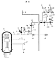
図25に、本発明の実施例5である気体供給装置を加圧水型原子炉における加圧器逃し弁57と主蒸気逃し弁61に適用した場合を示す。
FIG. 25 shows a case where the gas supply device according to the fifth embodiment of the present invention is applied to the
該図に示す如く、加圧水型原子炉は、原子炉格納容器48内に設置されている原子炉圧力容器59で発生した熱水を蒸気発生器60に送り、この蒸気発生器60で発生した蒸気により、原子炉建屋58外に設置されているタービン(図示せず)を回転させて電力を得ている。その際、原子炉圧力容器59で発生した熱水を加圧し、液体のままにするために、原子力圧力容器59の圧力、水位を保持する加圧器56が原子炉圧力容器59と蒸気発生器60の間に設けられている。また、タービンに蒸気を送る主蒸気配管41の途中には、主蒸気逃し弁61が元弁62Bを介して設けられており、主蒸気逃し弁61には、強制作動用シリンダ47Bが設けられている。なお、主蒸気配管41の主蒸気隔離弁42の手前側には、安全弁63Bが設置されている。
As shown in the figure, in the pressurized water reactor, the hot water generated in the
一方、加圧器56と、必要に応じて加圧器56の圧力を強制的に減圧する加圧器逃し弁57が元弁62Aを介して設けられており、加圧器逃し弁57には強制作動用シリンダ47Aが設けられている。また、加圧器56には安全弁63Aが設置されている。
On the other hand, a
この加圧器逃し弁57及び主蒸気逃し弁61もSBO時には操作が不能となるため、上述した第1及び第2の切替弁3A及び3B、第2の電磁弁2B、第3及び第4の電磁弁5A及び5Bを設けることで、原子炉圧力容器59の減圧又は蒸気発生器60の減圧を安全に実施できるようになる。
Since the
即ち、図25に示す加圧水型原子炉に適用される気体供給装置は、原子炉圧力容器59に配管によって接続され、原子力圧力容器59の圧力、水位を保持する加圧器56に設置され、必要に応じて加圧器56の圧力を強制的に減圧する加圧器逃し弁57及び原子炉圧力容器59に配管によって接続され、原子炉圧力容器59に冷却水を供給する蒸気発生器60内の蒸気を逃す主蒸気逃し弁61と、加圧器逃し弁57を開動作させるために、内部に蓄えられている空気又は窒素を加圧器逃し弁57に供給する強制作動用シリンダ47A及び主蒸気逃し弁61を開動作させるために、内部に蓄えられている空気又は窒素を主蒸気逃し弁61に供給する強制作動用シリンダ47Bと、それぞれの配管の途中に設置され、加圧器逃し弁57に供給する強制作動用シリンダ47A及び主蒸気逃し弁61に供給する強制作動用シリンダ47Bへの空気又は窒素の流れの開閉を行うそれぞれの第1の電磁弁2A1及び2A2と、それぞれの第1の電磁弁2A1及び2A2に空気又は窒素を供給するそれぞれの第1及び第2の空気又は窒素供給源(特に図示しないが、実施例1と同様なボンベ4Aや液体窒素を気化させて窒素ガスを供給する)と、それぞれの第1の電磁弁2A1及び2A2の排気ライン11A1及び11A2に設置され、それぞれの第1の電磁弁2A1及び2A2からの排気と、それぞれの第1の電磁弁2A1及び2A2への給気を切替えると共に、電源喪失時にはそれぞれの第1の電磁弁2A1及び2A2に空気又は窒素を供給するために、それぞれの第2の空気又は窒素供給源との接続に切替えられるそれぞれの第1の切替弁3A1及び3A2と、それぞれの第1の切替弁3A1及び3A2のそれぞれの第2の空気又は窒素供給源側の配管の途中に設置され、それぞれの第1の切替弁3A1及び3A2の給気側へのリークを防止するそれぞれの隔離弁6A及び6Bとを備えて構成されている。
That is, the gas supply apparatus applied to the pressurized water reactor shown in FIG. 25 is connected to the
また、それぞれの隔離弁6A及び6Bは、それぞれの第1の電磁弁2A1及び2A2が動作不能の際に、通常運転時の電源とは異なるそれぞれの第2の電源によって動作して、それぞれの隔離弁6A及び6Bを開にし、それぞれの第1の切替弁3A1及び3A2にそれぞれの第2の空気又は窒素供給源(ボンベ4A)から空気又は窒素を供給するそれぞれの第2の電磁弁2B1及び2B2を備えている。
In addition, the
更に、それぞれの第2の空気又は窒素供給源(ボンベ4A)は、それぞれの隔離弁6A及び6Bが設置されている配管の延長線上に設置されているそれぞれの第3の電磁弁5A1及び5A2でそれぞれの第2の空気又は窒素供給源(ボンベ4A)の流れの開閉が行われ、かつ、それぞれの第2の電磁弁2B1及び2B2が設置されている配管の延長線上には、それぞれの第2の切替弁3B1及び3B2及びそれぞれの第3の空気又は窒素供給源(ボンベ4B)からの気体の流れの開閉を行う第4の電磁弁5B1及び5B2がそれぞれ設置され、それぞれの第2の電源が喪失した際には、それぞれの第4の電磁弁5B1及び5B2を開にして、それぞれの第3の空気又は窒素供給源(ボンベ4B)から空気又は窒素を供給し、それぞれの第2の切替弁3B1及び3B2が排気から給気に切り替わることでそれぞれの第2の電磁弁2B1及び2B2を操作してそれぞれの隔離弁6A及び6Bを開操作するものである。
Further, each second air or nitrogen supply source (
つまり、本実施例では、第1の電磁弁2A2の排気ライン11A2に、第1の電磁弁2A2からの排気と、この第1の電磁弁2A2への給気を切替える第1の切替弁3A2が設置され、この第1の切替弁3A2は、電源喪失時には、第1の電磁弁2A2に空気又は窒素を供給するために、第3の電磁弁5A2を介して第2の空気又は窒素供給源であるボンベ4Aとの接続に切替えられるものである。
That is, in this embodiment, the first switching valve 3A2 for switching the exhaust from the first electromagnetic valve 2A2 and the supply of air to the first electromagnetic valve 2A2 is provided in the exhaust line 11A2 of the first electromagnetic valve 2A2. The first switching valve 3A2 is installed with a second air or nitrogen supply source via the third electromagnetic valve 5A2 in order to supply air or nitrogen to the first electromagnetic valve 2A2 when power is lost. It is switched to connection with a
更に、上述した隔離弁6Bは、通常時は第2の電源を用いて第2の気体供給源(ボンベ4A)からの給気で作動するが、第2の電源が喪失した時は,第2の切替弁3B2に第3の気体供給源(ボンベ4B)の給気ライン17B2に繋がる第4の電磁弁5B2より気体を供給することで、第2の切替弁3B2を第2の電磁弁2B2の排気ライン11B2側に切り替えることで、隔離弁6Bに気体を供給することができ、隔離弁6Bを開閉することができるようになっている。
Further, the isolation valve 6B described above is normally operated by supplying air from the second gas supply source (
これにより、隔離弁6Bを開操作することが可能となり、原子炉建屋58外に設置されている空気又は窒素が貯蔵されている第2の気体供給源であるボンベ4Aから第3の電磁弁5A2を介して、制御用空気又は窒素が隔離弁6Bを経由して第1の切替弁3A2に給気でき、通常時は排気側に接続されている第1の切替弁3A2を給気側に切り替え、作動用の空気又は窒素を第1の電磁弁2A2に供給することで、第1及び第2の電源喪失時においても、主蒸気逃し弁61を作動させる強制作動用シリンダ47Bに、空気又は窒素が供給されて作動させることが可能となる。
As a result, the isolation valve 6B can be opened, and the third electromagnetic valve 5A2 from the
また、原子炉圧力容器59と、原子力圧力容器59の圧力、水位を保持する加圧器56との配管の途中に設置され、必要に応じて加圧器56の圧力を強制的に減圧する加圧器逃し弁57は、この加圧器逃し弁57を開動作させるために、内部に蓄えられている空気又は窒素を加圧器逃し弁57に供給する強制作動用シリンダ47Aと、配管の途中に設置され、強制作動用シリンダ47Aへの空気又は窒素の流れの開閉を行う第1の電磁弁2A1を備えており、第1の電磁弁2A1には、ボンベ4等の第2の空気又は窒素供給源により空気又は窒素を供給するようになっている。
Further, a pressurizer escape is installed in the middle of the piping between the
そして、本実施例では、第1の電磁弁2A1の排気ライン11A1に、第1の電磁弁2A1からの排気と、この第1の電磁弁2A1への給気を切替える第1の切替弁3A1が設置され、この第1の切替弁3A1は、電源喪失時には、第1の電磁弁2A1に空気又は窒素を供給するために、隔離弁6Aを介して第2の空気又は窒素供給源であるボンベ4との接続に切替えられるものである。
In this embodiment, the first switching valve 3A1 for switching the exhaust from the first solenoid valve 2A1 and the supply of air to the first solenoid valve 2A1 is provided in the exhaust line 11A1 of the first solenoid valve 2A1. The first switching valve 3A1 is installed in a
更に、上述した隔離弁6Aは、通常時は第2の電源を用いて第2の気体供給源(ボンベ4A)からの給気で作動するが、第2の電源が喪失した時は、第2の切替弁3B1に第3の気体供給源(ボンベ4B)の給気ライン17B1に繋がる第4の電磁弁5B1より気体を供給することで、第2の切替弁3B1を第2の電磁弁2B1の排気ライン11B1側に切り替えることで、隔離弁6Aに気体を供給することができ、隔離弁6Aを開閉することができるようになっている。
Further, the
これにより、隔離弁6Aを開操作することが可能となり、原子炉建屋58外に設置されている空気又は窒素が貯蔵されている第2の気体供給源であるボンベ4Aから第3の電磁弁5A1を介して、制御用空気又は窒素が隔離弁6Aを経由して第1の切替弁3A1に給気でき、通常時は排気側に接続されている第1の切替弁3A1を給気側に切り替え、作動用の空気又は窒素を第1の電磁弁2A1に供給することで、第1及び第2の電源喪失時においても、加圧逃し弁57を作動させる強制作動用シリンダ47Aに、空気又は窒素が供給されて作動させることが可能となる。
Thereby, it becomes possible to open the
このような本実施例の構成とすることにより、SBO時に、加圧器逃し弁57や主蒸気逃し弁61の操作が不能となっても、第1の切替弁3A1及び3A2、第2の切替弁3B1及び3B2を切替えることにより、ボンベ4A、4Bなどの気体供給源から空気又は窒素等の気体を供給できるため、上述した実施例と同様な効果を得ることができる。
By adopting such a configuration of the present embodiment, even when the operation of the
なお、上述した実施例では、空気又は窒素作動弁について説明したが、安全弁、逃し弁又は安全逃し弁についても適用可能である。また、原子力プラント以外に化学プラント、石油プラント、発電設備等にも本発明は適用できる。また、供給する気体として、空気又は窒素以外に二酸化炭素が考えられる。 In the above-described embodiment, the air or nitrogen operating valve has been described. However, the present invention can also be applied to a safety valve, a relief valve, or a safety relief valve. Further, the present invention can be applied to chemical plants, petroleum plants, power generation facilities and the like in addition to nuclear plants. In addition to air or nitrogen, carbon dioxide can be considered as the gas to be supplied.
図26に、本発明の気体供給装置の実施例6を示す。該図に示す本実施例は、第1の切替弁3Aが第1の電磁弁2Aの排気側に接続されており、隔離弁6として電動弁を設けたものである。
FIG. 26 shows a sixth embodiment of the gas supply device of the present invention. In the present embodiment shown in the figure, the
これにより、第1の電磁弁2Aが電源喪失などにより動作不能の場合、電動弁から成る隔離弁6を開にすることで、第1の切替弁3Aに第3の気体供給源であるボンベ4Aから気体を供給することを可能となる。
As a result, when the first
なお、本実施例では、上述した第2の電源が喪失した時のバックアップである第3の気体供給源(ボンベ4B)及び第4の電磁弁5B等は備えていない。
In addition, in a present Example, the 3rd gas supply source (
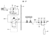
図27に、本発明の気体供給装置の実施例7を示す。該図に示す本実施例は、第1の切替弁3Aが第1の電磁弁2Aの排気側に接続されており、隔離弁6として電磁弁を設けたものである。
FIG. 27 shows a seventh embodiment of the gas supply device of the present invention. In the present embodiment shown in the figure, the
これにより、第1の電磁弁2Aが電源喪失などにより動作不能の場合、電磁弁から成る隔離弁6を開にすることで、第1の切替弁3Aに第3の気体供給源であるボンベ4Aから気体を供給することを可能となる。
Thus, when the first
なお、本実施例では、上述した第2の電源が喪失した時のバックアップである第3の気体供給源(ボンベ4B)及び第4の電磁弁5B等は備えていない。
In addition, in a present Example, the 3rd gas supply source (
図28に、本発明の気体供給装置の実施例8を示す。該図に示す本実施例は、第1の切替弁3Aが第1の電磁弁2Aの排気側に接続されており、隔離弁6として破列板を設けたものである。
FIG. 28 shows an eighth embodiment of the gas supply device of the present invention. In the present embodiment shown in the figure, the
これにより、第1の電磁弁2Aが電源喪失などにより動作不能の場合、破列板から成る隔離弁6を破って開にすることで、第1の切替弁3Aに第3の気体供給源であるボンベ4Aから気体を供給することを可能となる。
As a result, when the first
なお、本実施例では、上述した第2の電源が喪失した時のバックアップである第3の気体供給源(ボンベ4B)及び第4の電磁弁5B等は備えていない。
In addition, in a present Example, the 3rd gas supply source (
図29乃至図35に、本発明の気体供給装置の実施例9を示す。該図に示す本実施例は、第1の電磁弁2Aの給気ライン10Aの途中及び第1の切替弁3Aの第2の気体供給源(ボンベ4A)側の配管の途中に、上述した隔離弁6とは異なる隔離弁A(6C)及びB(6D)がそれぞれ設置されており、それぞれの隔離弁A(6C)及びB(6D)には、第1の気体供給源(IA系:計装空気供給系統設備)及び第2の気体供給源(ボンベ4A)からの気体が同一の供給用配管20Cを介して供給されるようになっている。
29 to 35 show a ninth embodiment of the gas supply device of the present invention. In this embodiment shown in the figure, the isolation described above is provided in the middle of the
そして、第1の電磁弁2Aの給気ライン10Aの途中に設置されている隔離弁A(6C)は、通常時の待機時には開状態で保持され第1の気体供給源からの気体が供給可能であり、通常時の給気時には、隔離弁A(6C)を介して第1の気体供給源からの気体が第1の電磁弁2Aに供給されると共に、通常時の排気時には第1の電磁弁2Aへの第1の気体供給源からの気体の供給を止め、空気作動弁アクチュエータ1に給気された気体を第1の電磁弁2A及び第1の切替弁3Aを介して該第1の切替弁3Aの排気ライン13Aから排出し、かつ、電源喪失時の給気時には第1の気体供給源又は第2の気体供給源(ボンベ4A)からの気体を、第1の切替弁3Aのボンベ4A側の配管の途中に設置された隔離弁B(6D)を開状態にし、第1の切替弁3Aを介して第1の電磁弁2Aに送るようにしたものである。なお、64はボンベ元弁、65は排気止め弁である。
The isolation valve A (6C) installed in the middle of the
以下、図面を用いて説明する。 Hereinafter, it demonstrates using drawing.
図29は、本実施例の通常時の待機状態を示す。通常時の待機状態では、隔離弁A(6C)は、通常待機時には開状態で保持されており、通常の気体供給源(第1の気体供給源)であるIA系などの気体供給を通すようになっている。その際には、第1の電磁弁2Aの給気ライン10A、隔離弁B(6D)及びボンベ元弁64は、いずれも閉状態である。
FIG. 29 shows a normal standby state of this embodiment. In the normal standby state, the isolation valve A (6C) is held in the open state during the normal standby state so as to pass a gas supply such as an IA system that is a normal gas supply source (first gas supply source). It has become. At that time, the
図30は、本実施例の通常時の給気状態を示す。通常時の給気状態では、隔離弁A(6C)を介して、通常の気体供給源(第1の気体供給源)であるIA系などの気体を開操作された第1の電磁弁2Aに送ることで、弁本体(図示せず)を開閉する空気作動弁アクチュエータ1に気体が供給されて該通常時の排気状態が動作し、弁本体が作動する(図30では、開作動であり逆の作動も可能である)。
FIG. 30 shows a normal supply state of the present embodiment. In the normal air supply state, the first
図31は、本実施例の通常時の排気状態を示す。通常時の排気状態では、通常の気体供給源(第1の気体供給源)であるIA系などの気体を閉操作された第1の電磁弁2Aに送り、空気作動弁アクチュエータ1に給気されていた気体が、第1の電磁弁2A及び第1の切替弁3Aを介して排気ライン13Aより排出されることで、弁本体(図示せず)を開閉する空気作動弁アクチュエータ1が動作し、弁本体が作動する(図31では、閉作動であり逆の作動も可能である)。
FIG. 31 shows the normal exhaust state of the present embodiment. In a normal exhaust state, a gas such as an IA system that is a normal gas supply source (first gas supply source) is sent to the closed first
図32は、本実施例の電源喪失時の待機状態を示す。電源喪失時の待機状態では、隔離弁A(6C)は、電源喪失により閉状態になり、待機している。その際には、第1の電磁弁2Aの給気ライン10A、隔離弁B(6D)及びボンベ元弁64は、いずれも閉状態である。
FIG. 32 shows a standby state when the power supply is lost in this embodiment. In the standby state when the power is lost, the isolation valve A (6C) is closed due to the loss of the power and is on standby. At that time, the
図33は、本実施例の電源喪失時の給気状態を示す。電源喪失時の給気状態では、隔離弁A(6C)を介して、通常の気体供給源(第1の気体供給源)であるIA系又は第2の気体供給源であるボンベ4などの気体を隔離弁B(6D)を開状態にして、第1の切替弁3Aを介して第1の電磁弁2Aに送ることで、弁本体(図示せず)を開閉する空気作動弁アクチュエータ1が動作し、弁本体が作動する(図33では、開作動であり逆の作動も可能である)。
FIG. 33 shows an air supply state when the power source is lost in this embodiment. In the supply state at the time of power loss, the gas such as the IA system that is a normal gas supply source (first gas supply source) or the
図34及び図35は、本実施例の電源喪失時の排気状態を示す。電源喪失時の排気状態では、通常の気体供給源(第1の気体供給源)であるIA系などの気体を排気止弁65を開にすることで、空気作動弁アクチュエータ1に給気し、この給気された気体を第1の電磁弁2A及び第1の切替弁3Aを介して排気ライン13Bより排出することで、弁本体(図示せず)を開閉る空気作動弁アクチュエータ1が動作し、弁本体が作動する(図34及び図35では、閉作動であり逆の作動も可能である)。
34 and 35 show the exhaust state when the power source is lost in this embodiment. In the exhaust state at the time of power loss, a gas such as an IA system that is a normal gas supply source (first gas supply source) is supplied to the air-operated
図36及び図37は、上述した実施例9の気体供給装置の変形例を示し、図36は、建屋21の内側に配置されている空気作動弁アクチュエータ1に給気された気体を、第1の電磁弁2A及び第1の切替弁3Aを介し、電磁弁B(6D)を閉にし排気止弁65を開にして排気ライン13Bより建屋21の内側に戻す(排出する)ようにしたものである。図37は、図36の隔離弁A(6C)、隔離弁B(6D)及び排気止弁65を空気作動弁としたものである。
FIGS. 36 and 37 show a modification of the gas supply device of the ninth embodiment described above, and FIG. 36 shows the gas supplied to the air operated
このような本実施例の構成としても、その効果は実施例1と同様である。 The effect of the configuration of this embodiment is the same as that of the first embodiment.
なお、本発明は上記した実施例に限定されるものではなく、様々な変形例が含まれる。例えば、上記した実施例は本発明を分かり易く説明するために詳細に説明したものであり、必ずしも説明した全ての構成を備えるものに限定されるものではない。また、ある実施例の構成の一部を他の実施例の構成に置き換えることが可能であり、また、ある実施例の構成に他の実施例の構成を加えることも可能である。また、各実施例の構成の一部について、他の構成の追加・削除・置換をすることが可能である。 In addition, this invention is not limited to an above-described Example, Various modifications are included. For example, the above-described embodiments have been described in detail for easy understanding of the present invention, and are not necessarily limited to those having all the configurations described. Further, a part of the configuration of one embodiment can be replaced with the configuration of another embodiment, and the configuration of another embodiment can be added to the configuration of one embodiment. Further, it is possible to add, delete, and replace other configurations for a part of the configuration of each embodiment.
1…空気作動弁アクチュエータ、2A、2A1、2A2…第1の電磁弁、2B、2B1、2B2…第2の電磁弁、2C…第5の電磁弁、3A、3A1、3A2…第1の切替弁、3B、3B1、3B2…第2の切替弁、4A、4B…ボンベ、5A、5A1、5A2、5A3…第3の電磁弁、5B、5B1、5B2、5B3…第4の電磁弁、6、6A、6B…隔離弁、6C…隔離弁A、6D…隔離弁B、7…弁本体、8…シリンダ、10A、10A1、10A2…第1の電磁弁の給気ライン、10B、10B1、10B2…第2の電磁弁の給気ライン、10C…第5の電磁弁の排気ライン、11A、11A1、11A2…第1の電磁弁の排気ライン、11B、11B1、11B2…第2の電磁弁の排気ライン、13A…第1の切替弁の排気ライン、13B…第2の切替弁の排気ライン、14A…第1の切替弁の給気ライン、14B…第2の切替弁の給気ライン、17A、17A1、17A2…第3の電磁弁の給気ライン、17B、17B1、17B2…第4の電磁弁の給気ライン、18A、18A1、18A2…第3の電磁弁の排気ライン、18B、18B1、18B2…第4の電磁弁の排気ライン、20A1、20A2、20B1、20B2、51…配管、20C…供給用配管、21…建屋、40、59…原子炉圧力容器、41…主蒸気配管、42…主蒸気隔離弁、43…主蒸気逃し安全弁、44…高圧炉心注水系、45…低圧炉心注水系、46…外部注水ライン、47、47A、47B…強制作動用シリンダ、48…原子炉格納容器、50…空気又は窒素作動弁、52…開閉弁、53…非常用ガス処理系、54…排気塔、56…加圧器、57…加圧器逃し弁、58…原子炉建屋、60…蒸気発生器、61…主蒸気逃し弁、62A、62B…元弁、63A、63B…安全弁、64…ボンベ元弁、65…排気止弁。
DESCRIPTION OF
Claims (20)
前記隔離弁は、前記第1の電磁弁が動作不能の際に、通常運転時の電源とは異なる第2の電源によって動作して開にされ、前記第1の切替弁に前記第2の気体供給源から気体を供給する第2の電磁弁を備えていることを特徴とする気体供給装置。 Installed in the middle of a pipe for flowing at least gas in the plant, an operating valve for operating the valve body by the gas flowing in the pipe, and installed in the middle of the pipe to open and close the flow of gas to the operating valve A first solenoid valve to be performed; first and second gas supply sources for supplying gas to the first solenoid valve; and an exhaust line of the first solenoid valve; The first switching is switched to the connection with the second gas supply source in order to supply gas to the first solenoid valve when power is lost. A valve, and an isolation valve that is installed in the middle of the pipe on the second gas supply source side of the first switching valve and prevents leakage to the air supply side of the first switching valve,
The isolation valve is operated and opened by a second power supply different from the power supply during normal operation when the first solenoid valve is inoperable, and the second gas is supplied to the first switching valve. A gas supply device comprising a second electromagnetic valve for supplying gas from a supply source.
前記第2の気体供給源は、前記隔離弁が設置されている配管の延長線上に設置されている第3の電磁弁で気体の流れの開閉が行われることを特徴とする気体供給装置。 The gas supply device according to claim 1,
The second gas supply source is a gas supply device in which a gas flow is opened and closed by a third electromagnetic valve installed on an extension line of a pipe in which the isolation valve is installed.
前記第2の電磁弁が設置されている配管の延長線上には、第2の切替弁及び第3の気体供給源からの気体の流れの開閉を行う第4の電磁弁が設置され、前記第2の電源が喪失した際には、前記第4の電磁弁を開にして前記第3の気体供給源から気体を供給し、前記第2の切替弁が排気から給気に切り替わることで前記第2の電磁弁を操作して前記隔離弁を開操作することを特徴とする気体供給装置。 The gas supply device according to claim 2 ,
A fourth solenoid valve for opening and closing a gas flow from the second switching valve and the third gas supply source is installed on an extension line of the pipe in which the second solenoid valve is installed, When the second power source is lost, the fourth electromagnetic valve is opened to supply gas from the third gas supply source, and the second switching valve is switched from exhaust to supply air, thereby A gas supply device, wherein the isolation valve is opened by operating the electromagnetic valve 2.
前記第1の切替弁と前記隔離弁との間に、通常時には排気ライン側を開にし、前記第1の切替弁を閉にすると共に、電源喪失時には前記第1の切替弁を開にし、排気ライン側を閉にする第5の電磁弁が設置されていることを特徴とする気体供給装置。 In the gas supply device according to any one of claims 1 to 3,
The exhaust line side is normally opened between the first switching valve and the isolation valve, the first switching valve is closed, and when the power is lost, the first switching valve is opened, and the exhaust is exhausted. A gas supply device comprising a fifth solenoid valve for closing the line side.
前記作動弁は、空気作動弁、安全弁、逃し弁或いは安全逃し弁のいずれかであることを特徴とする気体供給装置。 In the gas supply device according to any one of claims 1 to 4,
The gas supply device according to claim 1, wherein the operation valve is one of an air operation valve, a safety valve, a relief valve, and a safety relief valve.
前記隔離弁は、空気作動弁、電磁弁、逃し弁或いは安全逃し弁或いは破裂板のいずれかであることを特徴とする気体供給装置。 In the gas supply device according to claim 1 or 2,
The gas supply device according to claim 1, wherein the isolation valve is one of an air operated valve, a solenoid valve, a relief valve, a safety relief valve, and a rupture plate.
前記第2及び第3の気体供給源の気体の流れの開閉を行う第3及び第4の電磁弁は、前記第1の電磁弁とは異なる電源種類で駆動される電磁弁又は手動弁を介してそれぞれの前記配管に接続されていることを特徴とする気体供給装置。 The gas supply device according to claim 3 , wherein
The third and fourth electromagnetic valves for opening and closing the gas flow of the second and third gas supply sources are via an electromagnetic valve or a manual valve driven by a power source type different from that of the first electromagnetic valve. And a gas supply device connected to each of the pipes.
前記第3及び第4の電磁弁の前記第1の電磁弁とは異なる電源種類で駆動される電磁弁は、少なくとも直流電源を動力源とするものであり、電源喪失時には前記直流電源を駆動原として前記電磁弁を駆動し、前記第2の電磁弁により開にされた前記隔離弁を介して前記第1の切替弁に前記第2の気体供給源から気体を供給するか、若しくは前記第2の電源が喪失した際には前記直流電源を駆動原として前記電磁弁を駆動し、前記第4の電磁弁を開にして前記第3の気体供給源から気体を供給し、前記第2の切替弁が排気から給気に切り替わることで前記第2の電磁弁を操作して前記隔離弁を開にして前記第1の切替弁に前記第2の気体供給源から気体を供給することを特徴とする気体供給装置。 The gas supply device according to claim 7, wherein
The solenoid valve driven by a power source type different from the first solenoid valve of the third and fourth solenoid valves uses at least a DC power source as a power source. When the power source is lost, the DC power source is driven. The electromagnetic valve is driven as follows, and gas is supplied from the second gas supply source to the first switching valve via the isolation valve opened by the second electromagnetic valve, or the second When the power source is lost, the solenoid valve is driven using the DC power source as a driving source, the fourth solenoid valve is opened, gas is supplied from the third gas supply source, and the second switching is performed. When the valve is switched from exhaust to supply, the second solenoid valve is operated to open the isolation valve and supply gas from the second gas supply source to the first switching valve. Gas supply device.
前記第3及び第4の電磁弁の前記第1の電磁弁とは異なる電源種類で駆動される電磁弁は、交流電源又は直流電源、直流電源、手動のそれぞれを動力源とする単独又は複数の切替弁から構成され、電源喪失時には前記直流電源を駆動原とする電磁切替弁を駆動するか、或いは手動切替弁を操作し、前記第2の電磁弁により開にされた前記隔離弁を介して前記第1の切替弁に前記第2の気体供給源から気体を供給するか、若しくは前記第2の電源が喪失した際には前記直流電源を駆動原とする電磁切替弁を駆動するか、或いは手動切替弁を操作し、前記第4の電磁弁を開にして前記第3の気体供給源から気体を供給し、前記第2の切替弁が排気から給気に切り替わることで前記第2の電磁弁を操作して前記隔離弁を開にして前記第1の切替弁に前記第2の気体供給源から気体を供給することを特徴とする気体供給装置。 The gas supply device according to claim 7, wherein
The solenoid valve driven by a power source type different from the first solenoid valve of the third and fourth solenoid valves is an AC power source or a DC power source, a DC power source, and a manual power source. It is composed of a switching valve, and when power is lost, it drives an electromagnetic switching valve with the DC power source as a driving source, or operates a manual switching valve, via the isolation valve opened by the second electromagnetic valve Supplying gas from the second gas supply source to the first switching valve, or driving an electromagnetic switching valve using the DC power source as a driving source when the second power source is lost, or The second electromagnetic valve is operated by operating a manual switching valve, opening the fourth electromagnetic valve, supplying gas from the third gas supply source, and switching the second switching valve from exhaust to air supply. Operate the valve to open the isolation valve and switch to the first switching valve Serial gas supply device and supplying the gas from the second gas source.
前記直流電源は、バッテリーであることを特徴とする気体供給装置。 In the gas supply device according to claim 8 or 9,
The gas supply apparatus according to claim 1, wherein the DC power source is a battery.
前記第2及び第3の気体供給源は、空気、窒素、又は二酸化炭素のいずれかが貯蔵されたボンベであることを特徴とする気体供給装置。 The gas supply device according to claim 3 , wherein
The second and third gas supply source of air, nitrogen, or a gas supply device which is a cylinder in which one of the carbon dioxide stored.
前記第1の電磁弁の給気ラインの途中及び前記第1の切替弁の前記第2の気体供給源側の配管の途中に、前記隔離弁とは異なる隔離弁A及びBがそれぞれ設置されており、前記隔離弁とは異なるそれぞれの隔離弁A及びBには、前記第1の気体供給源及び前記第2の気体供給源からの気体が同一の供給用配管を介して供給されることを特徴とする気体供給装置。 The gas supply device according to any one of claims 1 to 11,
Isolation valves A and B different from the isolation valve are installed in the middle of the air supply line of the first solenoid valve and in the middle of the pipe on the second gas supply source side of the first switching valve, respectively. In addition, each of the isolation valves A and B different from the isolation valve is supplied with the gas from the first gas supply source and the second gas supply source through the same supply pipe. A gas supply device.
前記第1の電磁弁の給気ラインの途中に設置されている隔離弁Aは、通常時の待機時には開状態で保持され前記第1の気体供給源からの気体が供給可能であり、通常時の給気時には前記隔離弁Aを介して前記第1の気体供給源からの気体が前記第1の電磁弁に供給されると共に、通常時の排気時には前記第1の電磁弁への前記第1の気体供給源からの気体の供給を止め、前記作動弁に給気された気体を前記第1の電磁弁及び前記第1の切替弁を介して該第1の切替弁の排気ラインから排出し、かつ、電源喪失時の給気時には前記第1の気体供給源又は前記第2の気体供給源からの気体を、前記第1の切替弁の前記第2の気体供給源側の配管の途中に設置された隔離弁Bを開状態にして前記第1の切替弁を介して前記第1の電磁弁に送ることを特徴とする気体供給装置。 The gas supply device according to claim 12, wherein
The isolation valve A installed in the middle of the air supply line of the first solenoid valve is held in an open state during normal standby and can supply gas from the first gas supply source. When the air is supplied, the gas from the first gas supply source is supplied to the first electromagnetic valve via the isolation valve A, and the first electromagnetic valve is supplied to the first electromagnetic valve during normal exhaust. The gas supply from the gas supply source is stopped, and the gas supplied to the operation valve is discharged from the exhaust line of the first switching valve via the first solenoid valve and the first switching valve. And at the time of air supply at the time of power loss, the gas from the first gas supply source or the second gas supply source is placed in the middle of the pipe on the second gas supply source side of the first switching valve. The installed isolation valve B is opened and sent to the first solenoid valve via the first switching valve. Gas supply device according to symptoms.
前記第1の電磁弁及び前記第1の切替弁は建屋の内側に、前記第1及び第2の気体供給源と前記隔離弁A、Bは建屋の外側に配置され、前記第1の切替弁の排気ラインからの排気が前記建屋の内側に戻されることを特徴とする気体供給装置。 The gas supply device according to claim 13, wherein
The first solenoid valve and the first switching valve are arranged inside the building, the first and second gas supply sources and the isolation valves A and B are arranged outside the building, and the first switching valve The exhaust gas from the exhaust line is returned to the inside of the building.
前記隔離弁A、Bは、空気作動弁であることを特徴とする気体供給装置。 The gas supply device according to any one of claims 12 to 14,
The isolation valves A and B are air operated valves.
前記隔離弁は、前記第1の電磁弁が動作不能の際に、通常運転時の電源とは異なる第2の電源によって動作して開にされ、前記第1の切替弁に前記第2の空気又は窒素供給源から空気又は窒素を供給する第2の電磁弁を備えていることを特徴とする原子力プラントの空気又は窒素供給装置。 It is provided in the middle of a pipe branched from the main steam pipe that supplies steam from the reactor pressure vessel stored in the reactor containment vessel to the turbine building, and opens when the reactor pressure exceeds a certain value. And a pipe installed in an emergency gas processing system for releasing the gas from the main containment safety valve or the reactor containment vessel in which the reactor pressure vessel is housed from the exhaust tower. An on-off valve is provided in the middle of the reactor, and when the pressure in the reactor containment vessel reaches a certain value or more, the on-off valve is opened to exhaust the gas in the reactor containment vessel from the emergency gas processing system. An air or nitrogen actuating valve, a cylinder for opening the main steam relief valve or a cylinder for supplying driving force to the on-off valve to open the air or nitrogen actuating valve; A first solenoid valve for opening and closing a flow of air or nitrogen; first and second air or nitrogen supply sources for supplying air or nitrogen to the first solenoid valve; and exhaust of the first solenoid valve Installed in a line to switch between exhaust from the first solenoid valve and air supply to the first solenoid valve, and to supply air or nitrogen to the first solenoid valve when power is lost A first switching valve that is switched to a connection to the air or nitrogen supply source, and the first switching valve that is installed in the middle of the pipe on the second air or nitrogen supply source side of the first switching valve. And an isolation valve that prevents leakage to the air supply side
The isolation valve is operated and opened by a second power source different from the power source during normal operation when the first solenoid valve is inoperable, and the second air is supplied to the first switching valve. Or the 2nd solenoid valve which supplies air or nitrogen from a nitrogen supply source is provided, The air or nitrogen supply apparatus of the nuclear power plant characterized by the above-mentioned.
前記第2の空気又は窒素供給源は、前記隔離弁が設置されている配管の延長線上に設置されている第3の電磁弁で第2の空気又は窒素供給源の流れの開閉が行われ、かつ、前記第2の電磁弁が設置されている配管の延長線上には、第2の切替弁及び第3の空気又は窒素供給源からの気体の流れの開閉を行う第4の電磁弁が設置され、前記第2の電源が喪失した際には、前記第4の電磁弁を開にして前記第3の空気又は窒素供給源から空気又は窒素を供給し、前記第2の切替弁が排気から給気に切り替わることで前記第2の電磁弁を操作して前記隔離弁を開操作することを特徴とする原子力プラントの空気又は窒素供給装置。 The nuclear plant air or nitrogen supply device according to claim 16,
The second air or nitrogen supply source is a third electromagnetic valve installed on an extension line of a pipe in which the isolation valve is installed, and the flow of the second air or nitrogen supply source is opened and closed. In addition, on the extension line of the pipe where the second electromagnetic valve is installed, a second switching valve and a fourth electromagnetic valve for opening and closing the gas flow from the third air or nitrogen supply source are installed. When the second power source is lost, the fourth solenoid valve is opened to supply air or nitrogen from the third air or nitrogen supply source, and the second switching valve is exhausted from the exhaust. An air or nitrogen supply device for a nuclear power plant, wherein the isolation valve is opened by operating the second electromagnetic valve by switching to air supply.
前記それぞれの隔離弁は、前記それぞれの第1の電磁弁が動作不能の際に、通常運転時の電源とは異なるそれぞれの第2の電源によって動作して開にされ、前記それぞれの第1の切替弁に前記それぞれの第2の空気又は窒素供給源から空気又は窒素を供給するそれぞれの第2の電磁弁を備えていることを特徴とする原子力プラントの空気又は窒素供給装置。 A pressurizer relief valve and a reactor connected to a reactor pressure vessel by piping and installed in a pressurizer for maintaining the pressure and water level of the reactor pressure vessel and forcibly reducing the pressure of the pressurizer as necessary A main steam relief valve that is connected to the pressure vessel by piping and supplies steam to the reactor pressure vessel to escape the steam in the steam generator, and is stored inside to open the pressurizer relief valve. A cylinder for supplying air or nitrogen to the pressurizer relief valve and a cylinder for supplying air or nitrogen stored therein to the main steam relief valve to open the main steam relief valve; A first solenoid valve installed in the middle of the pipe for opening and closing a flow of air or nitrogen to a cylinder supplied to the pressurizer relief valve and a cylinder supplied to the main steam relief valve; A first and a second air or nitrogen supply source for supplying air or nitrogen to the first solenoid valve, and an exhaust line of the respective first solenoid valve; Switching between the exhaust from the solenoid valve and the air supply to the respective first solenoid valve, and when the power is lost, the respective second air or nitrogen for supplying air or nitrogen to the respective first solenoid valve Each of the first switching valves to be switched to the connection with the nitrogen supply source, and the respective second air or nitrogen supply source side piping of each of the first switching valves, Each isolation valve for preventing leakage to the supply side of the first switching valve,
The respective isolation valves are operated and opened by respective second power sources different from the power source during normal operation when the respective first solenoid valves are inoperable, and the respective first solenoid valves are opened. An air or nitrogen supply device for a nuclear power plant, comprising a second solenoid valve for supplying air or nitrogen from the second air or nitrogen supply source to the switching valve.
前記それぞれの第2の空気又は窒素供給源は、前記それぞれの隔離弁が設置されている配管の延長線上に設置されているそれぞれの第3の電磁弁でそれぞれの第2の空気又は窒素供給源の流れの開閉が行われ、かつ、前記それぞれの第2の電磁弁が設置されている配管の延長線上には、それぞれの第2の切替弁及びそれぞれの第3の空気又は窒素供給源からの気体の流れの開閉を行う第4の電磁弁がそれぞれ設置され、前記それぞれの第2の電源が喪失した際には、前記それぞれの第4の電磁弁を開にして前記それぞれの第3の空気又は窒素供給源から空気又は窒素を供給し、前記それぞれの第2の切替弁が排気から給気に切り替わることで前記それぞれの第2の電磁弁を操作して前記それぞれの隔離弁を開操作することを特徴とする原子力プラントの空気又は窒素供給装置。 The air or nitrogen supply device for a nuclear power plant according to claim 18,
The second air or nitrogen supply source is a third electromagnetic valve installed on an extension line of a pipe where the respective isolation valve is installed. On the extension line of the pipe in which the respective second solenoid valves are installed, the flow from each second switching valve and each third air or nitrogen source is provided. When the fourth solenoid valves for opening and closing the gas flow are respectively installed and the second power source is lost, the fourth solenoid valves are opened and the third air is opened. Alternatively, air or nitrogen is supplied from a nitrogen supply source, and each of the second switching valves is switched from exhaust to supply of air to operate each of the second solenoid valves to open the respective isolation valves. Nuclear power characterized by Runt of air or nitrogen supply device.
前記第2及び第3の空気又は窒素供給源の空気又は窒素の流れの開閉を行う第3及び第4の電磁弁は、前記第1の電磁弁とは異なる電源種類で駆動される電磁弁又は手動弁を介してそれぞれの前記配管に接続されていることを特徴とする原子力プラントの空気又は窒素供給装置。 In the nuclear plant air or nitrogen supply device according to claim 17 or 19 ,
The third and fourth solenoid valves for opening and closing the second and third air or the air or nitrogen flow of the nitrogen supply source are solenoid valves driven by a power source type different from the first solenoid valve, or An air or nitrogen supply device for a nuclear power plant, which is connected to each of the pipes via a manual valve.
Priority Applications (3)
| Application Number | Priority Date | Filing Date | Title |
|---|---|---|---|
| JP2013259680A JP6208569B2 (en) | 2013-12-17 | 2013-12-17 | Gas supply device and air or nitrogen supply device of nuclear power plant |
| EP14190949.9A EP2869307A3 (en) | 2013-10-30 | 2014-10-29 | Gas supply apparatus and air or nitrogen supply apparatus of nuclear plant |
| US14/528,522 US9916908B2 (en) | 2013-10-30 | 2014-10-30 | Gas supply apparatus and air or nitrogen supply apparatus of nuclear plant |
Applications Claiming Priority (1)
| Application Number | Priority Date | Filing Date | Title |
|---|---|---|---|
| JP2013259680A JP6208569B2 (en) | 2013-12-17 | 2013-12-17 | Gas supply device and air or nitrogen supply device of nuclear power plant |
Publications (3)
| Publication Number | Publication Date |
|---|---|
| JP2015117721A JP2015117721A (en) | 2015-06-25 |
| JP2015117721A5 JP2015117721A5 (en) | 2016-08-25 |
| JP6208569B2 true JP6208569B2 (en) | 2017-10-04 |
Family
ID=53530638
Family Applications (1)
| Application Number | Title | Priority Date | Filing Date |
|---|---|---|---|
| JP2013259680A Active JP6208569B2 (en) | 2013-10-30 | 2013-12-17 | Gas supply device and air or nitrogen supply device of nuclear power plant |
Country Status (1)
| Country | Link |
|---|---|
| JP (1) | JP6208569B2 (en) |
Families Citing this family (3)
| Publication number | Priority date | Publication date | Assignee | Title |
|---|---|---|---|---|
| CN112797316A (en) * | 2019-11-14 | 2021-05-14 | 中核核电运行管理有限公司 | Emergency air source box for water gate of nuclear power station refueling pool |
| JP7349375B2 (en) | 2020-01-22 | 2023-09-22 | 三菱重工業株式会社 | Blowout panel opening device and blowout panel operating method |
| JP7201630B2 (en) * | 2020-02-20 | 2023-01-10 | 日立Geニュークリア・エナジー株式会社 | Valve drive system and emergency condensate system |
Family Cites Families (8)
| Publication number | Priority date | Publication date | Assignee | Title |
|---|---|---|---|---|
| JPS59116098A (en) * | 1982-12-24 | 1984-07-04 | 株式会社日立製作所 | Main steam isolation valve |
| JP2502224B2 (en) * | 1991-09-19 | 1996-05-29 | 株式会社日立製作所 | Air operated valve |
| JPH0618695A (en) * | 1992-07-03 | 1994-01-28 | Toshiba Corp | Valve travel monitoring controller for main steam isolation valve |
| JP3408612B2 (en) * | 1994-03-16 | 2003-05-19 | 宇宙開発事業団 | Gas pressure valve drive |
| WO2008156086A1 (en) * | 2007-06-18 | 2008-12-24 | Kabushiki Kaisha Toshiba | Drive system for safety valve |
| DE102009006533B4 (en) * | 2009-01-28 | 2011-06-30 | Siemens Aktiengesellschaft, 80333 | Actuator with an open / close valve |
| JP5665644B2 (en) * | 2011-04-27 | 2015-02-04 | 株式会社東芝 | Reactor containment decompression device and decompression method |
| JP5373213B1 (en) * | 2013-03-06 | 2013-12-18 | 日立Geニュークリア・エナジー株式会社 | Gas supply device and air or nitrogen supply device of nuclear power plant |
-
2013
- 2013-12-17 JP JP2013259680A patent/JP6208569B2/en active Active
Also Published As
| Publication number | Publication date |
|---|---|
| JP2015117721A (en) | 2015-06-25 |
Similar Documents
| Publication | Publication Date | Title |
|---|---|---|
| JP5373213B1 (en) | Gas supply device and air or nitrogen supply device of nuclear power plant | |
| JP6208569B2 (en) | Gas supply device and air or nitrogen supply device of nuclear power plant | |
| JP5781575B2 (en) | Remote control device and remote control device of nuclear power plant | |
| JP4768855B2 (en) | Safety valve drive system | |
| JP6434992B2 (en) | Passive decompression system for pressurized containers in nuclear reactors. | |
| JP2013228281A (en) | Emergency reactor core cooling system and nuclear reactor facilities provided with the same | |
| TWI505292B (en) | Nuclear reactor pressure vessel pressure relief equipment and the main steam release safety valve drive device | |
| JP6118231B2 (en) | Gas supply device and air or nitrogen supply device of nuclear power plant | |
| JP2011220822A (en) | Driving system for escape safety valves | |
| EP2869307A2 (en) | Gas supply apparatus and air or nitrogen supply apparatus of nuclear plant | |
| JP5665644B2 (en) | Reactor containment decompression device and decompression method | |
| US11355255B2 (en) | System and method for reducing atmospheric release of radioactive materials caused by severe accident | |
| JP2013104867A (en) | Nuclear power plant | |
| KR101195935B1 (en) | Apparatus of Electrical trip solenoid valve isolation block | |
| JP2009053049A (en) | Safety system of nuclear power plant | |
| CN112576805A (en) | Air supply system and method for pneumatic valve actuating mechanism | |
| JP2000009873A (en) | Hydrogen treatment facility in reactor container | |
| JP6522563B2 (en) | Motorized valve | |
| US20210313082A1 (en) | Steam generator accident mitigation system | |
| JP2012233696A (en) | Nuclear power plant | |
| CN111524618A (en) | Nuclear power station atmospheric emission device and system | |
| WO2021166325A1 (en) | Valve drive system and emergency condensate system | |
| KR102414701B1 (en) | Apparatus for reducing the release of Iodine to the atmosphere under severe accident | |
| JP2021117008A (en) | Blowout panel opening device and method for operating blowout panel | |
| US10012188B2 (en) | Pneumatic emergency shut-off valve |
Legal Events
| Date | Code | Title | Description |
|---|---|---|---|
| A521 | Written amendment |
Free format text: JAPANESE INTERMEDIATE CODE: A523 Effective date: 20160711 |
|
| A621 | Written request for application examination |
Free format text: JAPANESE INTERMEDIATE CODE: A621 Effective date: 20160711 |
|
| A977 | Report on retrieval |
Free format text: JAPANESE INTERMEDIATE CODE: A971007 Effective date: 20170522 |
|
| A131 | Notification of reasons for refusal |
Free format text: JAPANESE INTERMEDIATE CODE: A131 Effective date: 20170530 |
|
| A521 | Written amendment |
Free format text: JAPANESE INTERMEDIATE CODE: A523 Effective date: 20170627 |
|
| TRDD | Decision of grant or rejection written | ||
| A01 | Written decision to grant a patent or to grant a registration (utility model) |
Free format text: JAPANESE INTERMEDIATE CODE: A01 Effective date: 20170829 |
|
| A61 | First payment of annual fees (during grant procedure) |
Free format text: JAPANESE INTERMEDIATE CODE: A61 Effective date: 20170907 |
|
| R150 | Certificate of patent or registration of utility model |
Ref document number: 6208569 Country of ref document: JP Free format text: JAPANESE INTERMEDIATE CODE: R150 |