JP6208065B2 - Opposite piston type disc brake device - Google Patents
Opposite piston type disc brake device Download PDFInfo
- Publication number
- JP6208065B2 JP6208065B2 JP2014070987A JP2014070987A JP6208065B2 JP 6208065 B2 JP6208065 B2 JP 6208065B2 JP 2014070987 A JP2014070987 A JP 2014070987A JP 2014070987 A JP2014070987 A JP 2014070987A JP 6208065 B2 JP6208065 B2 JP 6208065B2
- Authority
- JP
- Japan
- Prior art keywords
- piston
- rotor
- brake device
- outer side
- disc brake
- Prior art date
- Legal status (The legal status is an assumption and is not a legal conclusion. Google has not performed a legal analysis and makes no representation as to the accuracy of the status listed.)
- Active
Links
Images


Classifications
-
- F—MECHANICAL ENGINEERING; LIGHTING; HEATING; WEAPONS; BLASTING
- F16—ENGINEERING ELEMENTS AND UNITS; GENERAL MEASURES FOR PRODUCING AND MAINTAINING EFFECTIVE FUNCTIONING OF MACHINES OR INSTALLATIONS; THERMAL INSULATION IN GENERAL
- F16D—COUPLINGS FOR TRANSMITTING ROTATION; CLUTCHES; BRAKES
- F16D55/00—Brakes with substantially-radial braking surfaces pressed together in axial direction, e.g. disc brakes
- F16D55/02—Brakes with substantially-radial braking surfaces pressed together in axial direction, e.g. disc brakes with axially-movable discs or pads pressed against axially-located rotating members
- F16D55/22—Brakes with substantially-radial braking surfaces pressed together in axial direction, e.g. disc brakes with axially-movable discs or pads pressed against axially-located rotating members by clamping an axially-located rotating disc between movable braking members, e.g. movable brake discs or brake pads
- F16D55/228—Brakes with substantially-radial braking surfaces pressed together in axial direction, e.g. disc brakes with axially-movable discs or pads pressed against axially-located rotating members by clamping an axially-located rotating disc between movable braking members, e.g. movable brake discs or brake pads with a separate actuating member for each side
-
- F—MECHANICAL ENGINEERING; LIGHTING; HEATING; WEAPONS; BLASTING
- F16—ENGINEERING ELEMENTS AND UNITS; GENERAL MEASURES FOR PRODUCING AND MAINTAINING EFFECTIVE FUNCTIONING OF MACHINES OR INSTALLATIONS; THERMAL INSULATION IN GENERAL
- F16D—COUPLINGS FOR TRANSMITTING ROTATION; CLUTCHES; BRAKES
- F16D55/00—Brakes with substantially-radial braking surfaces pressed together in axial direction, e.g. disc brakes
- F16D55/02—Brakes with substantially-radial braking surfaces pressed together in axial direction, e.g. disc brakes with axially-movable discs or pads pressed against axially-located rotating members
- F16D55/22—Brakes with substantially-radial braking surfaces pressed together in axial direction, e.g. disc brakes with axially-movable discs or pads pressed against axially-located rotating members by clamping an axially-located rotating disc between movable braking members, e.g. movable brake discs or brake pads
- F16D55/224—Brakes with substantially-radial braking surfaces pressed together in axial direction, e.g. disc brakes with axially-movable discs or pads pressed against axially-located rotating members by clamping an axially-located rotating disc between movable braking members, e.g. movable brake discs or brake pads with a common actuating member for the braking members
- F16D55/225—Brakes with substantially-radial braking surfaces pressed together in axial direction, e.g. disc brakes with axially-movable discs or pads pressed against axially-located rotating members by clamping an axially-located rotating disc between movable braking members, e.g. movable brake discs or brake pads with a common actuating member for the braking members the braking members being brake pads
- F16D55/226—Brakes with substantially-radial braking surfaces pressed together in axial direction, e.g. disc brakes with axially-movable discs or pads pressed against axially-located rotating members by clamping an axially-located rotating disc between movable braking members, e.g. movable brake discs or brake pads with a common actuating member for the braking members the braking members being brake pads in which the common actuating member is moved axially, e.g. floating caliper disc brakes
-
- F—MECHANICAL ENGINEERING; LIGHTING; HEATING; WEAPONS; BLASTING
- F16—ENGINEERING ELEMENTS AND UNITS; GENERAL MEASURES FOR PRODUCING AND MAINTAINING EFFECTIVE FUNCTIONING OF MACHINES OR INSTALLATIONS; THERMAL INSULATION IN GENERAL
- F16D—COUPLINGS FOR TRANSMITTING ROTATION; CLUTCHES; BRAKES
- F16D2121/00—Type of actuator operation force
- F16D2121/02—Fluid pressure
- F16D2121/04—Fluid pressure acting on a piston-type actuator, e.g. for liquid pressure
-
- F—MECHANICAL ENGINEERING; LIGHTING; HEATING; WEAPONS; BLASTING
- F16—ENGINEERING ELEMENTS AND UNITS; GENERAL MEASURES FOR PRODUCING AND MAINTAINING EFFECTIVE FUNCTIONING OF MACHINES OR INSTALLATIONS; THERMAL INSULATION IN GENERAL
- F16D—COUPLINGS FOR TRANSMITTING ROTATION; CLUTCHES; BRAKES
- F16D2121/00—Type of actuator operation force
- F16D2121/14—Mechanical
-
- F—MECHANICAL ENGINEERING; LIGHTING; HEATING; WEAPONS; BLASTING
- F16—ENGINEERING ELEMENTS AND UNITS; GENERAL MEASURES FOR PRODUCING AND MAINTAINING EFFECTIVE FUNCTIONING OF MACHINES OR INSTALLATIONS; THERMAL INSULATION IN GENERAL
- F16D—COUPLINGS FOR TRANSMITTING ROTATION; CLUTCHES; BRAKES
- F16D2121/00—Type of actuator operation force
- F16D2121/18—Electric or magnetic
- F16D2121/24—Electric or magnetic using motors
-
- F—MECHANICAL ENGINEERING; LIGHTING; HEATING; WEAPONS; BLASTING
- F16—ENGINEERING ELEMENTS AND UNITS; GENERAL MEASURES FOR PRODUCING AND MAINTAINING EFFECTIVE FUNCTIONING OF MACHINES OR INSTALLATIONS; THERMAL INSULATION IN GENERAL
- F16D—COUPLINGS FOR TRANSMITTING ROTATION; CLUTCHES; BRAKES
- F16D2125/00—Components of actuators
- F16D2125/18—Mechanical mechanisms
- F16D2125/20—Mechanical mechanisms converting rotation to linear movement or vice versa
- F16D2125/34—Mechanical mechanisms converting rotation to linear movement or vice versa acting in the direction of the axis of rotation
- F16D2125/36—Helical cams, Ball-rotating ramps
-
- F—MECHANICAL ENGINEERING; LIGHTING; HEATING; WEAPONS; BLASTING
- F16—ENGINEERING ELEMENTS AND UNITS; GENERAL MEASURES FOR PRODUCING AND MAINTAINING EFFECTIVE FUNCTIONING OF MACHINES OR INSTALLATIONS; THERMAL INSULATION IN GENERAL
- F16D—COUPLINGS FOR TRANSMITTING ROTATION; CLUTCHES; BRAKES
- F16D2125/00—Components of actuators
- F16D2125/18—Mechanical mechanisms
- F16D2125/20—Mechanical mechanisms converting rotation to linear movement or vice versa
- F16D2125/34—Mechanical mechanisms converting rotation to linear movement or vice versa acting in the direction of the axis of rotation
- F16D2125/40—Screw-and-nut
-
- F—MECHANICAL ENGINEERING; LIGHTING; HEATING; WEAPONS; BLASTING
- F16—ENGINEERING ELEMENTS AND UNITS; GENERAL MEASURES FOR PRODUCING AND MAINTAINING EFFECTIVE FUNCTIONING OF MACHINES OR INSTALLATIONS; THERMAL INSULATION IN GENERAL
- F16D—COUPLINGS FOR TRANSMITTING ROTATION; CLUTCHES; BRAKES
- F16D2200/00—Materials; Production methods therefor
- F16D2200/0004—Materials; Production methods therefor metallic
- F16D2200/0026—Non-ferro
- F16D2200/003—Light metals, e.g. aluminium
Landscapes
- Engineering & Computer Science (AREA)
- General Engineering & Computer Science (AREA)
- Mechanical Engineering (AREA)
- Braking Arrangements (AREA)
Description
この発明は、車両の制動を行う為に使用する対向ピストン型ディスクブレーキ装置の改良に関する。 The present invention relates to an improvement of an opposed piston type disc brake device used for braking a vehicle.
放熱性に優れると共に、走行時に於ける制動力の細かな調節が可能である等の理由から、自動車の前輪だけではなく、後輪に関しても、サービスブレーキを行う為のブレーキ装置としてディスクブレーキ装置を採用する場合がある。又、この場合、パーキングブレーキを行う為のブレーキ装置を、サービスブレーキに用いるディスクブレーキ装置とは別に設ける事も行われている。具体的には、例えば特許文献1、2に記載されている様に、パーキングブレーキ専用のドラムブレーキ装置を、サービスブレーキ専用のディスクブレーキ装置の内側に配置した構造(ドラムインハット式構造)や、パーキングブレーキ専用のディスクブレーキ装置を、サービスブレーキ専用のディスクブレーキ装置とは別に設ける構造(ツインキャリパ式構造)が採用されている。 The disc brake device is used as a brake device for service braking not only for the front wheels of the car but also for the rear wheels because of its excellent heat dissipation and the ability to finely adjust the braking force during driving. May be adopted. In this case, a brake device for performing the parking brake is also provided separately from the disc brake device used for the service brake. Specifically, as described in, for example, Patent Documents 1 and 2, a structure (drum-in-hat structure) in which a drum brake device dedicated to a parking brake is disposed inside a disk brake device dedicated to a service brake, A structure (a twin caliper type structure) in which a disc brake device dedicated to a parking brake is provided separately from a disc brake device dedicated to a service brake is employed.
図15は、サービスブレーキ専用のディスクブレーキ装置と、パーキングブレーキ専用のディスクブレーキ装置とを、それぞれ別に設けた従来構造の模式図を示している。図示の構造の場合、車輪と共に回転するロータ1の周囲に、サービスブレーキに用いる対向ピストン型ディスクブレーキ装置2と、パーキングブレーキに用いるフローティング型ディスクブレーキ装置3とを、周方向に離隔した状態で設けている。そして、これら2つのブレーキ装置2、3をそれぞれ、懸架装置を構成するナックル4に支持固定している。具体的には、前記対向ピストン型ディスクブレーキ装置2を構成するキャリパ5を、前記ナックル4に設けられた取付部(ステー)6aに対し支持固定すると共に、前記フローティング型ディスクブレーキ装置3を構成するサポート7を、前記ナックル4に設けられた別の取付部6bに対し支持固定している。
尚、本明細書及び特許請求の範囲中で「軸方向」、「径方向」、「周方向」とは、それぞれロータに関する「軸方向」、「径方向」、「周方向」を言う。
FIG. 15 is a schematic diagram of a conventional structure in which a disc brake device dedicated to service brakes and a disc brake device dedicated to parking brakes are separately provided. In the case of the illustrated structure, an opposed piston type disc brake device 2 used for a service brake and a floating type
In the present specification and claims, “axial direction”, “radial direction”, and “circumferential direction” refer to “axial direction”, “radial direction”, and “circumferential direction”, respectively, related to the rotor.
上述の様な構成を有する従来構造の場合、サービスブレーキ専用の対向ピストン型ディスクブレーキ装置2と、パーキングブレーキ専用のフローティング型ディスクブレーキ装置3とを、それぞれ別々に設けている。この為、サービスブレーキとパーキングブレーキとの2つの機能を備える1つのブレーキ装置として見た場合、装置全体が大型化すると共に重量が嵩む事が避けられない。又、前記ナックル4には、前記各ブレーキ装置2、3を支持固定する為の取付部6a、6bをそれぞれ設ける必要がある為、前記ナックル4の形状に関する自由度が低くなる。ナックルには、ダンパーを固定する為の取付部や、ロアアームを固定する為の取付部等を別途設ける必要があり、このナックルの形状に関する自由度を確保する事は、ナックル周辺の部材の設計の自由度を確保する上で重要になる。
In the case of the conventional structure having the above-described configuration, the opposed piston type disc brake device 2 dedicated to service brakes and the floating type
本発明は、上述の様な事情に鑑み、サービスブレーキとパーキングブレーキとの2つの機能を1つのブレーキ装置により実現し、装置の小型化及び軽量化を図ると共に、懸架装置の形状の自由度を向上すべく発明したものである。 In view of the circumstances as described above, the present invention realizes two functions of a service brake and a parking brake with a single brake device, thereby reducing the size and weight of the device and increasing the degree of freedom of the shape of the suspension device. Invented to improve.
本発明の対向ピストン型ディスクブレーキ装置は、キャリパ(対向ピストン型キャリパ)と、複数個のピストンと、少なくとも1対のパッドと、パーキング機構部とを備える。
このうちのキャリパは、車輪と共に回転するロータを挟んで設けられるアウタ、インナ両ボディ部と、このロータの外周縁よりも径方向外方位置で、これら両ボディ部の周方向両端部同士を連結する1対の連結部と、これら両ボディ部に、互いに対向して設けられた1組(合計2個)以上のシリンダとを有しており、前記ロータを跨ぐ状態で懸架装置(例えばナックル)に固定される。
又、前記各ピストンは、前記各シリンダ内にそれぞれ、液密に且つ軸方向に関する変位を可能に嵌装されている。
又、前記少なくとも1対のパッドは、前記ロータの両側に配置された状態で、前記キャリパに対し軸方向に関する変位を可能に支持されている。
又、前記パーキング機構部は、クランプ部材、及び、推力発生機構を有する。
このうちのクランプ部材は、アウタ側端部に押圧部を、インナ側端部に基部をそれぞれ有し、周方向に関して前記両連結部同士の間部分に配置され、前記各パッドのうちで、軸方向に関して前記押圧部と前記基部との間部分に存在する1対のパッドと、前記インナボディ部とを径方向外方から跨ぐ状態で、前記キャリパに対し軸方向に変位可能に支持されている。
又、前記推力発生機構は、その構成部材のうち、制動作動時に前記キャリパに対しインナ側に変位する部材(例えばスピンドル)を、前記基部に支持すると共に、制動作動時にアウタ側に変位する部材(例えばナット)を、前記インナボディ部に設けられたシリンダ内に配置している。
特に本発明の対向ピストン型ディスクブレーキ装置の場合には、サービスブレーキによる制動力を、前記各シリンダ内に圧油を送り込み、前記各ピストンにより前記各パッドを前記ロータの両側面に押し付ける事により発生させる。
これに対し、パーキングブレーキによる制動力を、前記推力発生機構の作動に伴って、前記アウタ側に変位する部材により直接又は間接的に、前記クランプ部材により径方向外方から跨れる1対のパッドのうちのインナ側のパッドを前記ロータの側面に押し付けると共に、この押し付けに伴う反力により前記クランプ部材を前記キャリパに対しインナ側に変位させ、前記押圧部により前記1対のパッドのうちのアウタ側のパッドを前記ロータの側面に押し付ける事により発生させる。
The opposed piston type disc brake device of the present invention includes a caliper (opposed piston type caliper), a plurality of pistons, at least one pair of pads, and a parking mechanism.
Of these, the caliper connects the outer and inner body parts provided across the rotor that rotates together with the wheels, and both ends in the circumferential direction of these body parts at positions radially outward from the outer peripheral edge of the rotor. A pair of connecting portions and a pair (two in total) of cylinders provided opposite to each other on these body portions, and a suspension device (for example, a knuckle) straddling the rotor Fixed to.
The pistons are fitted in the cylinders so as to be liquid-tight and displaceable in the axial direction.
The at least one pair of pads are supported on the caliper so as to be capable of displacement in the axial direction in a state of being disposed on both sides of the rotor.
The parking mechanism has a clamp member and a thrust generating mechanism.
Among these members, the clamp member has a pressing portion at the outer side end portion and a base portion at the inner side end portion, and is disposed in a portion between the two connection portions in the circumferential direction. With respect to the direction, it is supported so as to be displaceable in the axial direction with respect to the caliper in a state straddling a pair of pads existing at a portion between the pressing portion and the base portion and the inner body portion from the outside in the radial direction. .
The thrust generating mechanism includes a member (for example, a spindle) that is displaced toward the inner side with respect to the caliper during braking operation, among the constituent members, and is a member that is displaced toward the outer side during braking operation (for example, a spindle). For example, a nut) is disposed in a cylinder provided in the inner body portion.
Particularly in the case of the opposed piston type disc brake device of the present invention, the braking force generated by the service brake is generated by sending pressure oil into the cylinders and pressing the pads against both side surfaces of the rotor by the pistons. Let
On the other hand, a pair of pads straddling the braking force from the parking brake directly or indirectly by the clamp member from the outside in the radial direction, in accordance with the operation of the thrust generating mechanism, directly or indirectly by the member. Of the inner side of the pair of pads are pressed against the side surface of the rotor, and the clamping member is displaced toward the inner side with respect to the caliper by a reaction force caused by the pressing. It is generated by pressing the side pad against the side surface of the rotor.
上述の様な本発明を実施する場合には、例えば請求項2に記載した発明の様に、前記アウタ側に変位する部材により、このアウタ側に変位する部材と同じシリンダ内に嵌装されたインナ側のピストンを押圧する。 In carrying out the present invention as described above, for example, as in the invention described in claim 2, the member displaced to the outer side is fitted in the same cylinder as the member displaced to the outer side. Press the inner piston.
又、本発明を実施する場合には、例えば請求項3に記載した発明の様に、前記アウタ側に変位する部材と同じシリンダ内に嵌装されたインナ側のピストンを、アウタ側の大径部と、インナ側の小径部と、これら大径部と小径部とを連続する段差面とを備えた段付形状とする。そして、この段差面の面積と、前記インナ側のピストンと軸方向に対向する状態で設けられたアウタ側のピストンの受圧面積とを等しくする。 When carrying out the present invention, for example, as in the third aspect of the present invention, an inner side piston fitted in the same cylinder as the member that is displaced toward the outer side is replaced with a large outer diameter. A stepped shape is provided with a portion, a small-diameter portion on the inner side, and a stepped surface that continues the large-diameter portion and the small-diameter portion. And the area of this level | step difference surface and the pressure receiving area of the outer side piston provided in the state which opposes the said inner side piston in an axial direction are made equal.
又、本発明を実施する場合には、例えば請求項4に記載した発明の様に、前記押圧部を、アウタ側のピストンを跨ぐ様に配置する。
Moreover, when implementing this invention, the said press part is arrange | positioned so that the piston of an outer side may be straddled like the invention described in
又、本発明を実施する場合には、例えば請求項5に記載した発明の様に、前記推力発生機構を、外周面に雄ねじ部を有するスピンドルと、内周面に雌ねじ部を有し、このスピンドルに螺合したナットとを備えたものとする。 In carrying out the present invention, as in the invention described in claim 5, for example, the thrust generating mechanism includes a spindle having a male screw portion on the outer peripheral surface and a female screw portion on the inner peripheral surface. A nut screwed to the spindle is provided.
又、本発明を実施する場合には、例えば請求項6に記載した発明の様に、前記推力発生機構を、電動モータにより作動させる。 In carrying out the present invention, the thrust generating mechanism is operated by an electric motor, for example, as in the sixth aspect of the present invention.
上述の様な構成を有する本発明の対向ピストン型ディスクブレーキ装置によれば、それ単体で、サービスブレーキとパーキングブレーキとの2つの機能を発揮する事ができる為、それぞれ専用の装置を設ける場合に比べて、装置全体としての小型化及び軽量化を図れると共に、懸架装置の形状の自由度を向上できる。
即ち、本発明の場合には、油圧式のサービスブレーキとして機能する対向ピストン型ディスクブレーキ装置に、パーキングブレーキとして機能するパーキング機構部を一体的に設けて、1つの対向ピストン型ディスクブレーキ装置を構成している。しかも、本発明の場合には、前記パーキング機構部を構成する部材のうち、クランプ部材を、キャリパに対して、径方向に重畳(マウント)する状態で支持すると共に、推力発生機構の一部の部材(制動作動時にアウタ側に変位する部材)を、インナボディ部のシリンダ内に配置している。
この為、例えば前記図15に示した従来構造の場合の様に、サービスブレーキとパーキングブレーキの専用の2つの装置を周方向に離隔した状態で設ける構造や、単に周方向に連続させた構造と比べて、装置全体としての小型化(周方向に連続させた構造に対しては特に、周方向に関する全長の短縮化)及び軽量化を図れる。
更に、懸架装置に必要な取付部が、前記キャリパを支持固定するだけの1つで済む為、この懸架装置の形状に関する自由度を向上できる。
According to the opposed piston type disc brake device of the present invention having the above-described configuration, the two functions of the service brake and the parking brake can be exerted by itself, so that when each dedicated device is provided, In comparison, the overall size and weight of the device can be reduced, and the degree of freedom of the shape of the suspension device can be improved.
In other words, in the case of the present invention, a counter piston type disc brake device that functions as a parking brake is integrally provided on a counter piston type disc brake device that functions as a hydraulic service brake to constitute one counter piston type disc brake device. doing. In addition, in the case of the present invention, among the members constituting the parking mechanism, the clamp member is supported in a state of being superimposed (mounted) in the radial direction with respect to the caliper, and a part of the thrust generating mechanism is supported. A member (a member that is displaced toward the outer side during braking operation) is disposed in the cylinder of the inner body portion.
For this reason, for example, as in the case of the conventional structure shown in FIG. 15, a structure in which two dedicated devices for the service brake and the parking brake are separated in the circumferential direction, or a structure in which the devices are simply continuous in the circumferential direction. In comparison, the overall size of the apparatus can be reduced (especially for the structure continuous in the circumferential direction, the overall length in the circumferential direction can be shortened) and the weight can be reduced.
Furthermore, since only one mounting portion necessary for the suspension device is required to support and fix the caliper, the degree of freedom regarding the shape of the suspension device can be improved.
又、請求項2に記載した発明の場合には、サービスブレーキとパーキングブレーキとで、共通のピストン(アウタ側に変位する部材と同じシリンダ内に嵌装されたインナ側のピストン)を使用して制動力を得る事が可能になる。又、このインナ側のピストンに、前記アウタ側に変位する部材を通過させる為の加工を省略できる。
又、請求項3に記載した発明によれば、前記アウタ側に変位する部材と同じシリンダ内に嵌装されたインナ側のピストンと、このインナ側のピストンと軸方向に対向するアウタ側のピストンとの、サービスブレーキ時に於ける押圧力を互いに等しくできる。
更に、請求項4に記載した発明によれば、対向ピストン型ディスクブレーキ装置の周方向に関する更なる小型化を図れる。
In the case of the invention described in claim 2, the service brake and the parking brake use a common piston (an inner side piston fitted in the same cylinder as the member displaced to the outer side). A braking force can be obtained. Further, it is possible to omit processing for passing the member displaced toward the outer side through the inner piston.
According to a third aspect of the present invention, the inner piston fitted in the same cylinder as the outer displacement member, and the outer piston facing the inner piston in the axial direction. The pressing force during service braking can be made equal to each other.
Furthermore, according to the invention described in
[実施の形態の第1例]
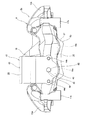
本発明の実施の形態の第1例に就いて、図1〜12により説明する。本例の対向ピストン型ディスクブレーキ装置2aは、サービスブレーキとパーキングブレーキとの2つの機能を合せ持つもので、キャリパ8と、1対のパッド9a、9b(アウタパッド9a、インナパッド9b)と、合計4個のピストン10、11(1個の兼用ピストン10と、3個のサービス専用ピストン11)と、パーキング機構部12とを備える。
[First example of embodiment]
A first example of the embodiment of the present invention will be described with reference to FIGS. The opposed piston type
このうちのキャリパ8は、前記アウタ、インナ両パッド9a、9bを、軸方向(図1、2の表裏方向、図3、4の左右方向、図5、6の上下方向)に移動可能に支持する。この様なキャリパ8は、アルミニウム合金等の軽合金を鋳造(ダイキャスト成形を含む)等により形成したもので、ロータ1(図15参照)を挟む状態で設けられたアウタボディ部13及びインナボディ部14と、これらアウタ、インナ両ボディ部13、14の周方向片側(図1、5の右側、図2、6の左側で、車両前進時に於ける回入側)端部と周方向他側(図1、5の左側、図2、6の右側で、車両前進時に於ける回出側)端部とをそれぞれ連結する連結部15a、15bとを備える。又、前記アウタ、インナ両ボディ部13、14の周方向中間部同士を中間連結部16により連結している。又、前記キャリパ8は、前記インナボディ部14に設けた1対の取付座17a、17bにより、ナックル4(図15参照)を構成する取付部に支持固定される。
Of these, the
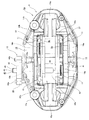
前記アウタ、インナ両ボディ部13、14のうち、周方向片側部分の内側には、回入側アウタシリンダ18a及び回入側インナシリンダ18bを互いに対向する状態で形成すると共に、周方向他側部分の内側には、回出側アウタシリンダ19a及び回出側インナシリンダ19bを互いに対向する状態で形成している。別な言い方をすれば、前記アウタボディ部13に、周方向に離隔する状態で、前記回入側アウタシリンダ18a及び前記回出側アウタシリンダ19aを形成すると共に、前記インナボディ部14に、周方向に離隔する状態で、前記回入側インナシリンダ18b及び前記回出側インナシリンダ19bを形成している。又、前記インナボディ部14のうち、軸方向に関して前記回入側インナシリンダ18bと整合する部分に、この回入側インナシリンダ18bに連通する(底面26に開口する)連通孔20を形成している。そして、合計4個のシリンダ18a、18b、19a、19bのうち、前記回入側インナシリンダ18b内に、サービスブレーキとパーキングブレーキとの両方で使用される兼用ピストン10を、残り3個のシリンダ18a、19a、19b内に、サービスブレーキにのみ使用されるサービス専用ピストン11を、油密に且つ軸方向に関する変位を可能に嵌装している。
Of the outer and
前記回入側インナシリンダ18bに嵌装された前記兼用ピストン10は、アルミニウム合金製で、アウタ側の大径部21と、インナ側の小径部22と、これら大径部21と小径部22とを連続する円輪状の段差面23とを備え、外周面を段付形状とした有底円筒状に構成している。又、前記兼用ピストン10の内側には、後述する推力発生機構40の構成部材の一部を配置する為の、インナ側にのみ開口した収納孔24を形成している。又、この収納孔24のアウタ側半部には、雌スプライン部25を形成している。
The dual-
この様な構成を有する前記兼用ピストン10は、前記大径部21を前記回入側インナシリンダ18b内に嵌装した状態で、前記小径部22を前記連通孔20内にがたつきなく挿入すると共に、前記段差面23を前記回入側インナシリンダ18bの底面26に対して軸方向に対向させている。そして、これら段差面23と、底面26と、前記回入側インナシリンダ18bの内周面と、前記小径部22の外周面との間に、圧油を導入する為の円環状の液圧室27aを形成している。又、前記回入側インナシリンダ18bの軸方向中間部内周面、及び、前記連通孔20の軸方向中間部内周面には、それぞれ断面矩形状のシール溝28a、28bを形成している。そして、これら各シール溝28a、28b内に、環状のピストンシール29a、29bをそれぞれ装着している。又、前記回入側インナシリンダ18bの内周面のうち、アウタ側開口部(アウタ側端部)には、内径寸法の大きくなった大径溝30aを形成している。そして、この大径溝30a内に、図示しないダストカバーを装着している。
The dual-
これに対し、前記残り3個のシリンダ18a、19a、19bに嵌装された前記サービス専用ピストン11は、アルミニウム合金製で、有底円筒状のピストン本体31と、このピストン本体31の先端部に固定された押圧部32とから構成している。又、このピストン本体31の底面33と、前記各シリンダ18a、19a、19bの奥部(内周面及び底面)との間に、圧油を導入する為の液圧室27bを形成している。又、前記各シリンダ18a、19a、19bの軸方向中間部内周面には、それぞれ断面矩形状のシール溝28cを形成している。そして、これら各シール溝28c内に、環状のピストンシール29cを装着している。又、前記各シリンダ18a、19a、19bの内周面のうちの開口部には、内径寸法の大きくなった大径溝30bを形成している。そして、この大径溝30b内に、図示しないダストカバーを装着している。
On the other hand, the service-
又、前記インナボディ部14に設けた導入口により、前記各液圧室27a、27bに、それぞれ圧油を送り込み可能としている。特に本例の場合には、前記兼用ピストン10を構成する円輪状の段差面23の面積(受圧面積)と、前記サービス専用ピストン11の底面33の面積(受圧面積)とを互いに等しくする事により、サービスブレーキ時に、前記兼用ピストン10と、この兼用ピストン10と軸方向に対向するサービス専用ピストン11とが、前記ロータ1の側面を互いに等しい押圧力で押圧できる様にしている。
Further, pressure oil can be fed into each of the
又、前記アウタボディ部13及び前記インナボディ部14の互いに対向する側面(アウタボディ部13のインナ側面、インナボディ部14のアウタ側面)のうち、周方向両端部には、軸方向に張り出した1対のガイド壁部34a、34bをそれぞれ設けている。又、これら両ガイド壁部34a、34bの周方向に互いに対向する側面のうち、径方向中間部に、これら両側面に対してほぼ直交する方向にガイド凹溝35a、35bをそれぞれ形成している。
Further, of the side surfaces of the
前記両パッド9a、9bは、ライニング(摩擦材)36と、このライニング36の裏面を支持した金属製の裏板(プレッシャプレート)37とから構成されている。又、この裏板37の周方向両側の側縁部の径方向中間部に、周方向両側にそれぞれ突出した1対の凸状の耳部38a、38bを設けている。つまり、これら両耳部38a、38bのうち、回入側の耳部38aは、前記裏板37の回入側側縁部の径方向中間部に、回入側に突出する状態で設けられており、回出側の耳部38bは、前記裏板37の回出側側縁部の径方向中間部に、回出側に突出する状態で設けられている。そして、これら両耳部38a、38bを、前記各ガイド凹溝35a、35bに、それぞれ緩く係合させている。これにより、前記各パッド9a、9bが、前記キャリパ8に対して、軸方向に関する変位を可能に、且つ、周方向及び径方向に関する変位を不能に支持されている。
Both the
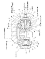
前記パーキング機構部12は、クランプ部材39と、推力発生機構40とを備えている。このうちのクランプ部材39は、周方向片端側の連結部15aと中間連結部16との周方向間部分に、前記両パッド9a、9b及び前記インナボディ部14を径方向外方から跨ぐ状態で設けられている。又、前記クランプ部材39は、アルミニウム系合金又は鉄系合金から造られており、全体形状が略コ字形で、アウタ側端部に設けられた二股状の押圧部41と、インナ側端部に設けられた基部42と、これら押圧部41と基部42とを連結するブリッジ部43とを有する。
The
又、本例の場合には、上述の様な構成を有するクランプ部材39を、前記押圧部41のインナ側面を前記アウタパッド9aの周方向片側半部のアウタ側面に、前記基部42のアウタ側面を前記インナボディ部14の周方向片側半部のインナ側面に、それぞれ対向させた状態で、前記キャリパ8に対して軸方向の変位を可能に支持している。
In the case of this example, the
この為に、本例の場合には、前記キャリパ8を構成するインナボディ部14の周方向片側部分に、1対のガイドピン(リバースピン)44a、44bのアウタ側端部をねじ止め固定している。そして、これら両ガイドピン44a、44bのうちで、前記インナボディ部14よりもインナ側に突出した部分の中間部を摺動部として、前記基部42に形成した1対のガイド孔内に、軸方向に関する変位を可能に緩く挿通している。尚、前記両ガイドピン44a、44bの周囲を、図示しない弾性材製の防塵ブーツにより覆う事もできる。
For this reason, in the case of this example, the outer side end portions of a pair of guide pins (reverse pins) 44a and 44b are screwed and fixed to one circumferential side portion of the
前記推力発生機構40は、回転運動を直線運動に変換し、作動時に軸方向に関する全長を変化させる送りねじ機構であり、スピンドル45と、ナット46とを備える。このうちのスピンドル45は、特許請求の範囲に記載したインナ側に変位する部材に相当し、先端部外周面に雄ねじ部を有しており、基端寄り部分に他の部分よりも大径のフランジ部47を有している。又、前記スピンドル45は、その基端部48を、前記クランプ部材39を構成する基部42に形成された支持孔49内に回転可能に支持しており、その先端部乃至中間部を、前記回入側インナシリンダ18bに嵌装された前記兼用ピストン10の収納孔24の内側にインナ側から挿入している。又、前記フランジ部47のインナ側面は、前記基部42のアウタ側面に形成された円形状の収納凹部50のアウタ側面に当接している。
The
一方、前記ナット46は、特許請求の範囲に記載したアウタ側に変位する部材に相当し、内周面に雌ねじ部を有しており、前記スピンドル45の先端部に螺合している。又、このナット46の外周面には、雄スプライン部51が形成されている。そして、この雄スプライン部51を、前記収納孔24のアウタ側半部内周面に形成された前記雌スプライン部25にスプライン係合させている。この為、前記ナット46は、前記兼用ピストン10の内側に、軸方向変位を可能に且つ相対回転を不能に配置されている。
On the other hand, the
又、本例の場合には、前記基部42のインナ側面に、図示しない電動駆動装置(MGU)を支持固定している。この電動駆動装置は、ケーシングと、このケーシング内にそれぞれ収納された電動モータ及び歯車式減速機等の減速機構とを備えている。又、この減速機構を構成する最終歯車を、前記スピンドル45を構成する基端部48に固定している。これにより、前記電動モータへの通電に基づいて、前記スピンドル45を回転させる事で、前記ナット46を前記キャリパ8(インナボディ部14)に対して軸方向に変位させる様にしている。
In this example, an electric drive unit (MGU) (not shown) is supported and fixed on the inner side surface of the
以上の様な構成を有する本例の対向ピストン型ディスクブレーキ装置2aにより、サービスブレーキを作動させる際には、前記各シリンダ18a、18b、19a、19bの液圧室27a、27bに、それぞれ圧油を送り込む。これにより、前記各ピストン10、11(1個の兼用ピストン10と3個のサービス専用ピストン11)を、それぞれ前記各シリンダ18a、18b、19a、19bから押し出し、前記両パッド9a、9bを前記ロータ1の両側面に押し付ける。この結果、このロータ1が、軸方向両側から強く押し付けられて、制動が行われる。この様に、本例の場合には、サービスブレーキによる制動力を、油圧の導入により、全てのピストン10、11を押し出す事により得る。
When the service brake is operated by the opposed piston type
これに対し、パーキングブレーキを作動させる際には、前記電動駆動装置を構成する電動モータに通電し、前記推力発生機構40を構成するスピンドル45を回転させて、前記ナット46を前記インナボディ部14に対してアウタ側に変位させる。そして、このナット46の先端部(アウタ側端部)を、前記兼用ピストン10の先端部のインナ側面に形成された受面52に押し付け、この兼用ピストン10により、前記インナパッド9bを前記ロータ1のインナ側面に押し付ける。又、この押し付けに伴う反力を、前記フランジ部47と前記収納凹部50との当接部を介して前記クランプ部材39に伝達し、このクランプ部材39を前記キャリパ8に対しインナ側に変位させ、前記押圧部41により、前記アウタパッド9aを前記ロータ1のアウタ側面に押し付ける。この結果、このロータ1が、軸方向両側から強く押し付けられて制動が行われる。この様に、本例の場合には、パーキングブレーキによる制動力を、フローティング型ブレーキの如き動作を行う、前記パーキング機構部12を駆動する事のみにより得る。
On the other hand, when operating the parking brake, the electric motor constituting the electric drive device is energized, the
又、パーキングブレーキを解除するには、前記電動モータにより、前記スピンドル45を制動作動時とは逆回転させる。これにより、前記ナット46を前記インナボディ部14に対してインナ側に変位させる。又、前記スピンドル45をこのインナボディ部14に対してアウタ側に変位させる事で、前記クランプ部材39をこのインナボディ部14に対してアウタ側に変位させる。又、前記兼用ピストン10を、前記両ピストンシール29a、29bの弾性復元力により、インナ側(ロータ1から離れる方向)に変位させる。この結果、前記アウタ、インナ両パッド9a、9bと前記ロータ1の両側面との間に、クリアランスが確保される。
In order to release the parking brake, the
以上の様な構成を有する本例の対向ピストン型ディスクブレーキ装置2aによれば、それ単体で、サービスブレーキとパーキングブレーキとの2つの機能を発揮する事ができる為、それぞれ専用の装置を設ける場合に比べて、装置全体としての小型化及び軽量化を図れると共に、ナックル4の形状の自由度を向上できる。
即ち、本例の場合には、油圧式のサービスブレーキとして機能する対向ピストン型ディスクブレーキ装置2aに、パーキングブレーキとして機能するパーキング機構部12を一体的に設けて、1つの対向ピストン型ディスクブレーキ装置2aを構成している。しかも、本例の場合には、前記パーキング機構部12を構成するクランプ部材39を、前記キャリパ8に対して、径方向に重畳(マウント)する状態で支持すると共に、前記パーキング機構部12を構成する推力発生機構40の一部の部材(ナット46及びスピンドル45の先端部乃至中間部)を、前記回入側インナシリンダ18b内に配置している。
According to the opposed piston type
That is, in the case of this example, the opposed piston type
この為、例えば前記図15に示した従来構造の場合の様に、サービスブレーキとパーキングブレーキの専用の2つの装置を周方向に離隔した状態で設ける構造や、単に周方向に連続させた構造と比べて、装置全体としての小型化(周方向に連続させた構造に対しては特に、周方向に関する全長の短縮化)及び軽量化を図れる。更に、本例の場合には、前記押圧部41を前記回入側アウタシリンダ18aに嵌装されたサービス専用ピストン11を跨ぐ形状(二股形状)としている為、周方向に隣接して設ける場合に比べて、周方向に関する全長を効果的に小さくできる。又、本例の構造によれば、前記ナックル4に必要な取付部が、前記キャリパ8を支持固定する為の1つで済む為、このナックル4の形状に関する自由度を向上できる。更に、サービスブレーキとパーキングブレーキとで、1対のパッド9a、9bを共通に使用する為、パッド数を低減する(図15の構造と比較して、2枚のパッドを減らす)事ができて、この面からも軽量化及び低コスト化を図れる。
For this reason, for example, as in the case of the conventional structure shown in FIG. 15, a structure in which two dedicated devices for the service brake and the parking brake are separated in the circumferential direction, or a structure in which the devices are simply continuous in the circumferential direction. In comparison, the overall size of the apparatus can be reduced (especially for the structure continuous in the circumferential direction, the overall length in the circumferential direction can be shortened) and the weight can be reduced. Furthermore, in the case of this example, since the
[実施の形態の第2例]
本発明の実施の形態の第2例に就いて、図13により説明する。本例の特徴は、回入側インナシリンダ18bに嵌装するピストンとして、前記実施の形態の第1例の様な、サービスブレーキとパーキングブレーキとの両方で使用される兼用ピストン10(図7、8等参照)ではなく、サービスブレーキにのみ使用するサービス専用ピストン52を採用している。このサービス専用ピストン52は、前記兼用ピストン10と同様に、その内側にインナ側に開口した収納孔24aを形成しているが、このサービス専用ピストン52の場合には、この収納孔24aがこのサービス専用ピストン52の先端部を貫通する状態で形成されている。又、この様な収納孔24aのうち、このサービス専用ピストン52の先端部を貫通した部分の内径は、推力発生機構40を構成するナット46を挿通可能な大きさとしている。尚、前記収納孔24aの貫通の有無以外の構成は、本例のサービス専用ピストン52と、前記兼用ピストン10とは同じである。
[Second Example of Embodiment]
A second example of the embodiment of the present invention will be described with reference to FIG. The feature of this example is that the
以上の様な構成を有する本例の場合にも、サービスブレーキを作動させる際には、各シリンダ18b(18a、19a、19b)の液圧室27a(27b)に、それぞれ圧油を送り込む。これにより、合計4個のサービス専用ピストン52、(11)を、それぞれ前記各シリンダ18b(18a、19a、19b)から押し出し、1対のパッド9a、9b(図6、9等参照)をロータ1(図15参照)の両側面に押し付ける。
Also in the case of this example having the above-described configuration, when operating the service brake, the pressure oil is fed into the
これに対し、パーキングブレーキを作動させる際には、前記推力発生機構40を構成するスピンドル45を回転させて、前記ナット46を前記インナボディ部14に対してアウタ側に変位させる。そして、このナット46の先端部(アウタ側端部)を、前記サービス専用ピストン52の先端部のアウタ側面から突出させて、前記ナット46により直接、前記インナパッド9bを前記ロータ1のインナ側面に押し付ける。又、この押し付けに伴う反力を、フランジ部47と収納凹部50との当接部を介してクランプ部材39に伝達し、このクランプ部材39をキャリパ8に対しインナ側に変位させ、押圧部41(図7等参照)により、アウタパッド9aを前記ロータ1のアウタ側面に押し付ける。
On the other hand, when operating the parking brake, the
以上の様な構成を有する本例の場合には、前記収納孔24aの軸方向両端部が開口している為、この収納孔24aの加工作業性を向上する事ができる。又、この収納孔24a内に、前記推力発生機構40の構成部材の一部(例えばナット46)を組み込む為の組立作業性を向上する事もできる。
その他の構成及び作用効果に就いては、前述した実施の形態の第1例の場合と同様である。
In the case of this example having the above-described configuration, since both end portions in the axial direction of the
About another structure and an effect, it is the same as that of the case of the 1st example of embodiment mentioned above.
[実施の形態の第3例]
本発明の実施の形態の第3例に就いて、図14を参照しつつ説明する。本例の場合には、前記実施の形態の第1例の場合と同様、回入側インナシリンダ18b内に、兼用ピストン10aを嵌装している。この兼用ピストン10aは、円筒部52と、この円筒部52のアウタ側端部を塞ぐ底部53とを備えた、有底円筒状に構成されており、前記実施の形態の第1例の場合の様に外周面形状を段付き形状とはしていない。又、本例の場合、前記インナシリンダ18bの内周面の1箇所にのみシール溝28dを形成しており、このシール溝28dに、ピストンシール29dを装着している。又、前記回入側インナシリンダ18bの底面26と前記兼用ピストン10aとの間部分に、液圧室27cを形成している。
[Third example of embodiment]
A third example of the embodiment of the present invention will be described with reference to FIG. In the case of this example, as in the case of the first example of the above embodiment, the dual-
又、本例の場合、推力発生機構40aとして、送りねじ機構54と、ボールランプ機構55とを組み合わせたものを使用している。このうちの送りねじ機構54は、スピンドル45aと、前記ボールランプ機構55の駆動側ロータとして機能するナット46aとを備える。このボールランプ機構55は、このナット46aと、被駆動側ロータ56と、複数個のボール57とを備える。これらナット46a及び被駆動側ロータ56の互いに対向する面の円周方向複数箇所には、それぞれ複数箇所(例えば3〜4箇所)に、それぞれが軸方向に見た形状が円弧形である、駆動側ランプ部58と被駆動側ランプ部59とを設けている。これら各ランプ部58、59の、軸方向に関する深さは、円周方向に関して漸次変化しているが、変化の方向は前記各駆動側ランプ部58と前記各被駆動側ランプ部59とで、互いに逆方向としている。従って、前記ナット46aと前記被駆動側ロータ56とを相対回転させ、前記各ボール57を前記各ランプ部58、59に沿って転動させると、前記ナット46aと前記被駆動側ロータ56同士の間隔が大きな力で拡張できる(拡げられる)。
In the case of this example, a combination of the
この様なボールランプ機構55は、前記兼用ピストン10aの内径側に緩く内嵌したケース60の内側に配置している。この状態で、このケース60の一端部(図14の左端部)を径方向内方に折り曲げた折り曲げ部61を、前記被駆動側ロータ56の外周縁のアウタ側端部に形成した係止段部62に係合させている。又、前記ナット46aの先端部(図14の左側端部)のインナ側面と、前記ケース60の内周面のインナ側寄りに固定した円輪部材63との間に、付勢ばね64を設けている。この付勢ばね64は、前記ナット46aに対して、このナット46aの作動時(制動力発生時)の回転方向と反対方向の弾性力、及び、アウタ側への弾性力を付与している。
Such a ball ramp mechanism 55 is arranged inside a
又、前記ケース60の中間部の円周方向の一部(例えば120〜180度の範囲)に、このケース60の外周面から内周面に掛けて貫通する切り欠き65を形成している。そして、前記ナット46aの先端部外周面の一部に設けた係止部(図示省略)を、この切り欠き65に係合させている。この様な構造により、このナット46aが過度(120〜180度以上)に回転する事を防止している。
Further, a
又、前記被駆動側ロータ56の先端部の外周面のうち、前記ケース60からアウタ側に突出しており、アウタ側に向かうに従って外径が小さくなる方向に傾斜したロータ側傾斜面66を、前記ピストン19aの底部53のインナ側面に形成され、このロータ側傾斜面66と同方向に同角度で傾斜した、部分円すい凹面状の受面67に対向させている。そして、これら両面66、67同士の当接に基づく、くさび効果により、前記被駆動側ロータ56の回転を阻止している。
Further, of the outer peripheral surface of the tip end portion of the driven
以上の様な構成を有する本例の場合にも、サービスブレーキを作動させる際には、各シリンダ18b(18a、19a、19b)の液圧室27c、(27b)に、それぞれ圧油を送り込む。これにより、合計4個のピストン10a(1個の兼用ピストン10a及び3個のサービス専用ピストン11)を、それぞれ前記各シリンダ18b(18a、19a、19b)から押し出し、1対のパッド9a、9b(図6、9等参照)をロータ1(図15参照)の両側面に押し付ける。
Also in the case of this example having the above-described configuration, when operating the service brake, the pressure oil is fed into the
これに対し、パーキングブレーキを作動させる際には、前記送りねじ機構54を構成するスピンドル45aを回転させる。この回転駆動の初期段階では前記ナット46aが、前記両面66、67同士の摩擦抵抗と、前記付勢ばね64等の抵抗とにより回転しない。そして、前記ナット46aが、前記スピンドル45aの雄ねじ部と、このナット46aの雌ねじ部との螺合に基づいて、前記被駆動側ロータ56と共に、前記スピンドル45aの先端側に平行移動(ロータ1に向けて、回転せずに移動)する。この平行移動により、前記兼用ピストン10aがアウタ側に押し出され、前記インナパッド9bを前記ロータ1のインナ側面に押し付ける。又、この押し付けに伴う反力によりクランプ部材39をキャリパ8に対しインナ側に変位させ、押圧部41(図7等参照)により、前記アウタパッド9aを前記ロータ1のアウタ側面に押し付ける。この結果、前記各部の隙間が喪失し、前記ナット46aと前記被駆動側ロータ56とがそれ以上前記ロータ1に向けて移動する事に対する抵抗が大きくなると、このうちのナット46aが前記スピンドル45aと共に回転し、このナット46aと前記被駆動側ロータ56とが相対回転する。すると、前記各ボール57が、転動しながら、前記各ランプ部58、59のうちで浅い側に移動し、前記ナット46aと前記被駆動側ロータ56同士の間隔が拡がる。これら各ランプ部58、59の傾斜角度は緩いので、これらナット46aと被駆動側ロータ56同士の間隔を拡げる力は大きくなり、前記インナ、アウタ両パッド9a、9bを前記ロータ1の両側面に、前記兼用ピストン10a及び前記押圧部41により、大きな力で押し付けて、制動を行える。
On the other hand, when operating the parking brake, the
尚、上述した様な送りねじ機構54とボールランプ機構55とを組み合わせて構成される推力発生機構40aの構造及び作用に就いては、例えば特許文献3に記載される等、従来から広く知られている為、これ以上の詳しい説明は省略する。又、本発明を実施する場合に、推力発生機構は、送りねじ機構のみから成る構造や、これにボールランプ機構を組み合わせた構造以外にも、例えばカムローラ機構等を組み合わせた構造を採用できる。
その他の構成及び作用効果に就いては、前記実施の形態の第1例の場合と同様である。
The structure and operation of the
About another structure and an effect, it is the same as that of the case of the 1st example of the said embodiment.
上述した実施の形態では、パーキングブレーキによる制動力を、電動駆動装置を利用して得る構造に就いてのみ説明したが、本発明はこの様な構造に限定されない。即ち、パーキングブレーキによる制動力を、パーキング機構部の駆動により発生させる事ができれば、例えば特許文献4等に開示された構造の様な、パーキングレバーによる駆動構造を採用する事もできる。又、使用するパッド数に就いても、2枚に限定されず、例えば4枚や6枚設ける事もできる。
In the above-described embodiment, only the structure in which the braking force by the parking brake is obtained using the electric drive device has been described, but the present invention is not limited to such a structure. That is, if the braking force generated by the parking brake can be generated by driving the parking mechanism, a driving structure using a parking lever such as the structure disclosed in
1 ロータ
2、2a 対向ピストン型ディスクブレーキ装置
3 フローティング型ディスクブレーキ装置
4 ナックル
5 キャリパ
6a、6b 取付部
7 サポート
8 キャリパ
9a アウタパッド
9b インナパッド
10、10a 兼用ピストン
11 サービス専用ピストン
12 パーキング機構部
13 アウタボディ部
14 インナボディ部
15a、15b 連結部
16 中間連結部
17a、17b 取付座
18a 回入側アウタシリンダ
18b 回入側インナシリンダ
19a 回出側アウタシリンダ
19b 回出側インナシリンダ
20 連通孔
21 大径部
22 小径部
23 段差面
24 収納孔
25 雌スプライン部
26 底面
27a、27b、27c 液圧室
28a、28b、28c、28d シール溝
29a、29b、29c、29d ピストンシール
30a、30b 大径溝
31 ピストン本体
32 押圧部
33 底面
34a、34b ガイド壁部
35a、35b ガイド凹溝
36 ライニング
37 裏板
38a、38b 耳部
39 クランプ部材
40、40a 推力発生機構
41 押圧部
42 基部
43 ブリッジ部
44a、44b ガイドピン
45、45a スピンドル
46、46a ナット
47 フランジ部
48 基端部
49 支持孔
50 収納凹部
51 雄スプライン部
52 円筒部
53 底部
54 送りねじ機構
55 ボールランプ機構
56 被駆動側ロータ
57 ボール
58 駆動側ランプ部
59 被駆動側ランプ部
60 ケース
61 折り曲げ部
62 係止段部
63 円輪部材
64 付勢ばね
65 切り欠き
66 ロータ傾斜面
67 受面
DESCRIPTION OF SYMBOLS 1 Rotor 2, 2a Opposite piston type disc brake device 3 Floating type disc brake device 4 Knuckle 5 Caliper 6a, 6b Mounting part 7 Support 8 Caliper 9a Outer pad 9b Inner pad 10, 10a Combined piston 11 Piston for service 12 Parking mechanism part 13 Outer body Part 14 Inner body part 15a, 15b Connecting part 16 Intermediate connecting part 17a, 17b Mounting seat 18a Rotating side outer cylinder 18b Rotating side inner cylinder 19a Rotating side outer cylinder 19b Rotating side inner cylinder 20 Communication hole 21 Large diameter part 22 Small-diameter portion 23 Stepped surface 24 Storage hole 25 Female spline portion 26 Bottom surface 27a, 27b, 27c Hydraulic chamber 28a, 28b, 28c, 28d Seal groove 29a, 29b, 29c, 29d Piston seal 30a, 30b Large-diameter groove 31 Piston body 32 Press part 33 Bottom surface 34a, 34b Guide wall part 35a, 35b Guide concave groove 36 Lining 37 Back plate 38a, 38b Ear part 39 Clamp member 40, 40a Thrust generating mechanism 41 Press part 42 Base 43 Bridge portion 44a, 44b Guide pin 45, 45a Spindle 46, 46a Nut 47 Flange portion 48 Base end portion 49 Support hole 50 Storage recess 51 Male spline portion 52 Cylindrical portion 53 Bottom portion 54 Feed screw mechanism 55 Ball ramp mechanism 56 Driven side Rotor 57 Ball 58 Drive side lamp part 59 Driven side lamp part 60 Case 61 Bending part 62 Locking step part 63 Ring member 64 Energizing spring 65 Notch 66 Rotor inclined surface 67 Receiving surface
Claims (6)
前記各シリンダ内にそれぞれ、液密に且つ軸方向に関する変位を可能に嵌装されたピストンと、
前記ロータの両側に配置された状態で、前記キャリパに対し軸方向に関する変位を可能に支持された少なくとも1対のパッドと、
アウタ側端部に押圧部を、インナ側端部に基部をそれぞれ有し、周方向に関して前記両連結部同士の間部分に配置され、前記各パッドのうちで軸方向に関して前記押圧部と前記基部との間部分に存在する1対のパッドと前記インナボディ部とを径方向外方から跨ぐ状態で、前記キャリパに対し軸方向に変位可能に支持されたクランプ部材、及び、その構成部材のうち制動作動時に前記キャリパに対しインナ側に変位する部材を前記基部に支持すると共に、制動作動時にアウタ側に変位する部材を前記インナボディ部に設けられたシリンダ内に配置した推力発生機構を有する、パーキング機構部と、を備え、
サービスブレーキによる制動力を、前記各シリンダ内に圧油を送り込み、前記各ピストンにより前記各パッドを前記ロータの両側面に押し付ける事により発生させ、
パーキングブレーキによる制動力を、前記推力発生機構の作動に伴って、前記アウタ側に変位する部材により直接又は間接的に、前記クランプ部材により径方向外方から跨れる1対のパッドのうちのインナ側のパッドを前記ロータの側面に押し付けると共に、この押し付けに伴う反力により前記クランプ部材を前記キャリパに対しインナ側に変位させ、前記押圧部により前記1対のパッドのうちのアウタ側のパッドを前記ロータの側面に押し付ける事により発生させる、
事を特徴とする対向ピストン型ディスクブレーキ装置。 An outer and inner body parts provided across a rotor that rotates together with the wheels, and a pair of connecting parts that connect both ends in the circumferential direction of the both body parts at a radially outer position than the outer peripheral edge of the rotor. And a caliper that is fixed to the suspension device in a state of straddling the rotor, and having one or more sets of cylinders provided opposite to each other on both the body parts,
A piston fitted in each cylinder so as to be liquid-tight and capable of displacement in the axial direction;
At least one pair of pads supported on the caliper so as to be axially displaceable in a state of being disposed on both sides of the rotor;
The outer side end portion has a pressing portion, the inner side end portion has a base portion, and is disposed at a portion between the two connection portions in the circumferential direction, and the pressing portion and the base portion in the axial direction among the pads. A clamp member supported so as to be displaceable in the axial direction with respect to the caliper in a state straddling a pair of pads existing in a portion between the inner body part and the inner body part, and a component member thereof A member that is displaced toward the inner side with respect to the caliper during braking operation is supported by the base, and a member that is displaced toward the outer side during braking operation is disposed in a cylinder provided in the inner body portion. A parking mechanism,
A braking force by a service brake is generated by sending pressure oil into each cylinder and pressing each pad against both side surfaces of the rotor by each piston,
The inner brake of the pair of pads straddling from the outside in the radial direction by the clamp member, directly or indirectly by the member that displaces the braking force by the parking brake to the outer side in accordance with the operation of the thrust generating mechanism. The pad on the side is pressed against the side surface of the rotor, and the clamping member is displaced toward the inner side with respect to the caliper by a reaction force caused by the pressing, and the pad on the outer side of the pair of pads is moved by the pressing portion. Generated by pressing against the side of the rotor,
The opposed piston type disc brake device.
Priority Applications (5)
| Application Number | Priority Date | Filing Date | Title |
|---|---|---|---|
| JP2014070987A JP6208065B2 (en) | 2014-03-31 | 2014-03-31 | Opposite piston type disc brake device |
| EP15773913.7A EP3128199B1 (en) | 2014-03-31 | 2015-03-27 | Opposed piston-type disc brake device |
| PCT/JP2015/059723 WO2015152074A1 (en) | 2014-03-31 | 2015-03-27 | Opposed piston-type disc brake device |
| CN201580018192.1A CN106164527B (en) | 2014-03-31 | 2015-03-27 | Opposed pistons type disc brake assembly |
| US15/129,952 US10119582B2 (en) | 2014-03-31 | 2015-03-27 | Opposed-piston type disk brake device |
Applications Claiming Priority (1)
| Application Number | Priority Date | Filing Date | Title |
|---|---|---|---|
| JP2014070987A JP6208065B2 (en) | 2014-03-31 | 2014-03-31 | Opposite piston type disc brake device |
Publications (3)
| Publication Number | Publication Date |
|---|---|
| JP2015194165A JP2015194165A (en) | 2015-11-05 |
| JP2015194165A5 JP2015194165A5 (en) | 2016-11-24 |
| JP6208065B2 true JP6208065B2 (en) | 2017-10-04 |
Family
ID=54240398
Family Applications (1)
| Application Number | Title | Priority Date | Filing Date |
|---|---|---|---|
| JP2014070987A Active JP6208065B2 (en) | 2014-03-31 | 2014-03-31 | Opposite piston type disc brake device |
Country Status (5)
| Country | Link |
|---|---|
| US (1) | US10119582B2 (en) |
| EP (1) | EP3128199B1 (en) |
| JP (1) | JP6208065B2 (en) |
| CN (1) | CN106164527B (en) |
| WO (1) | WO2015152074A1 (en) |
Families Citing this family (22)
| Publication number | Priority date | Publication date | Assignee | Title |
|---|---|---|---|---|
| GB201514925D0 (en) * | 2015-08-21 | 2015-10-07 | Caparo Vehicle Products Ltd | A brake caliper,a braking apparatus and a vehicle |
| TWI616603B (en) * | 2016-05-20 | 2018-03-01 | Tw Racing Parts Inc | Electronic parking calipers |
| US9989115B2 (en) * | 2016-08-26 | 2018-06-05 | Akebono Brake Industry Co., Ltd | Disc brake system |
| US10184536B2 (en) | 2016-09-23 | 2019-01-22 | Akebono Brake Industry Co., Ltd. | Brake piston |
| JP6624094B2 (en) | 2017-01-27 | 2019-12-25 | トヨタ自動車株式会社 | Braking device |
| DE102018100072B4 (en) | 2017-01-27 | 2020-06-18 | Toyota Jidosha Kabushiki Kaisha | Brake unit |
| DE102017116323A1 (en) * | 2017-07-19 | 2019-01-24 | Lucas Automotive Gmbh | Disc brake, disc brake system and parking brake system |
| JP6871829B2 (en) * | 2017-09-06 | 2021-05-12 | 曙ブレーキ工業株式会社 | Caliper for opposed piston type disc brake |
| DE102018102511A1 (en) * | 2018-02-05 | 2019-08-08 | Lucas Automotive Gmbh | Disc brake with floating caliper and fixed caliper |
| US10487896B2 (en) * | 2018-04-14 | 2019-11-26 | Mando Corporation | Piston brake caliper and brake system |
| CN109690118B (en) * | 2018-05-30 | 2020-06-19 | 吴茂庭 | Disc type hydraulic anti-lock brake and brake system |
| JP7043353B2 (en) | 2018-06-14 | 2022-03-29 | 曙ブレーキ工業株式会社 | Opposed piston type disc brake device |
| US11125288B2 (en) | 2018-08-21 | 2021-09-21 | Akebono Brake Industry Co., Ltd | Disc brake system |
| US11655867B2 (en) | 2018-08-21 | 2023-05-23 | Akebono Brake Industry Co., Ltd | Disc brake system |
| JP7124686B2 (en) * | 2018-12-17 | 2022-08-24 | トヨタ自動車株式会社 | disc brake device |
| US11105385B2 (en) * | 2019-02-11 | 2021-08-31 | ZF Active Safety US Inc. | Twin piston caliper with electric parking brake and method of operating such a twin piston caliper with electric parking brake |
| CN110219910B (en) * | 2019-05-08 | 2021-04-16 | 浙江吉利控股集团有限公司 | Brake caliper |
| US20210348663A1 (en) * | 2020-05-08 | 2021-11-11 | Akebono Brake Industry Co., Ltd. | Opposed brake caliper with park brake function |
| US11313425B2 (en) * | 2020-07-13 | 2022-04-26 | Kema Enterprise Co., Ltd. | Motor transmission unit for electronic parking brake device |
| US11542994B2 (en) * | 2020-09-23 | 2023-01-03 | Akebono Brake Industry Co., Ltd | Brake system with support structure for moving body |
| US11554766B2 (en) | 2021-03-17 | 2023-01-17 | ZF Active Safety US Inc. | Hydraulically assisted electric parking brake |
| KR102588379B1 (en) * | 2021-09-27 | 2023-10-12 | 현대모비스 주식회사 | Brake apparatus for vehicle |
Family Cites Families (16)
| Publication number | Priority date | Publication date | Assignee | Title |
|---|---|---|---|---|
| US3321049A (en) * | 1965-05-12 | 1967-05-23 | Kelsey Hayes Co | Mechanical floating head brake |
| US5769189A (en) * | 1995-03-03 | 1998-06-23 | Lucas Industries Public Limited Company | Automotive parking brake and parking brake system for motor vehicles |
| JPH0960667A (en) * | 1995-08-22 | 1997-03-04 | Akebono Brake Ind Co Ltd | Drum-in disk brake |
| JP3901329B2 (en) * | 1998-02-10 | 2007-04-04 | 日清紡績株式会社 | Disc brake device |
| JP2002021892A (en) | 2000-07-04 | 2002-01-23 | Akebono Brake Ind Co Ltd | Drum-in-disc brake device |
| CN2690660Y (en) | 2003-12-09 | 2005-04-06 | 刘连忠 | Disc type braker pull out and compensation mechanism with parking braking |
| DE102005055085B4 (en) * | 2005-09-29 | 2020-09-24 | Robert Bosch Gmbh | Combined service and parking brake device as well as a method for performing emergency braking |
| EP1924782B1 (en) | 2005-10-05 | 2009-04-15 | Freni Brembo S.P.A. | Disc braking system for a vehicle combining service and parking brake |
| DE102006037660A1 (en) * | 2005-11-04 | 2007-07-19 | Continental Teves Ag & Co. Ohg | Hydraulic vehicle brake with integrated electric motor-operated parking brake |
| JP2007177995A (en) * | 2005-11-29 | 2007-07-12 | Akebono Brake Ind Co Ltd | Disc brake actuator provided with parking operation mechanism |
| JP5513914B2 (en) * | 2010-02-03 | 2014-06-04 | 曙ブレーキ工業株式会社 | Disc brake device with electric parking mechanism |
| JP2012246988A (en) * | 2011-05-26 | 2012-12-13 | Toyota Motor Corp | Disc brake device |
| ITMI20120232A1 (en) * | 2012-02-16 | 2013-08-17 | Freni Brembo Spa | ASSEMBLY OF SERVICE CLAMP AND STATION |
| CN107795611B (en) | 2012-08-10 | 2019-08-20 | 日本轻金属株式会社 | Disk type brake device clamp |
| JP2015124812A (en) * | 2013-12-26 | 2015-07-06 | 曙ブレーキ工業株式会社 | Disc brake device |
| JP2015215074A (en) * | 2014-05-13 | 2015-12-03 | 曙ブレーキ工業株式会社 | Disc brake device |
-
2014
- 2014-03-31 JP JP2014070987A patent/JP6208065B2/en active Active
-
2015
- 2015-03-27 CN CN201580018192.1A patent/CN106164527B/en active Active
- 2015-03-27 WO PCT/JP2015/059723 patent/WO2015152074A1/en active Application Filing
- 2015-03-27 US US15/129,952 patent/US10119582B2/en active Active
- 2015-03-27 EP EP15773913.7A patent/EP3128199B1/en active Active
Also Published As
| Publication number | Publication date |
|---|---|
| US10119582B2 (en) | 2018-11-06 |
| CN106164527B (en) | 2019-08-02 |
| US20170130788A1 (en) | 2017-05-11 |
| EP3128199A4 (en) | 2017-11-22 |
| EP3128199A1 (en) | 2017-02-08 |
| CN106164527A (en) | 2016-11-23 |
| WO2015152074A1 (en) | 2015-10-08 |
| EP3128199B1 (en) | 2020-11-04 |
| JP2015194165A (en) | 2015-11-05 |
Similar Documents
| Publication | Publication Date | Title |
|---|---|---|
| JP6208065B2 (en) | Opposite piston type disc brake device | |
| WO2015174434A1 (en) | Disk brake device | |
| WO2015098780A1 (en) | Disc-brake device | |
| EP3591250B1 (en) | Opposed-piston type disc brake device | |
| WO2015098781A1 (en) | Disc brake device | |
| US20150323026A1 (en) | Ball ramp mechanism, linear motion actuator, and electric disc brake device | |
| JP2013113378A (en) | Disk brake | |
| WO2015137359A1 (en) | Floating-type disc brake | |
| JP7063195B2 (en) | Friction brake, in-vehicle device | |
| JP2018179116A (en) | Wet brake | |
| JP2014122648A (en) | Ball ramp mechanism, linear motion actuator and electrically-driven disc brake device | |
| WO2016006581A1 (en) | Disc brake device | |
| JP2016028215A (en) | Disc brake | |
| JP5879032B2 (en) | Disc brake | |
| US20230286480A1 (en) | Disc brake device | |
| JP2014134215A (en) | Ball lamp mechanism, linear motion actuator, and electric disc brake device | |
| WO2017138415A1 (en) | Electric brake device and method for manufacturing electric brake device | |
| JP4155869B2 (en) | Disc brake with parking mechanism | |
| JP7419175B2 (en) | disc brake | |
| JP2009058102A (en) | Pad clip and multiple disc brake | |
| JP2017089871A (en) | Disc brake device | |
| JP2019116945A (en) | Disc brake device | |
| JP4798147B2 (en) | Brake structure | |
| JP4719577B2 (en) | Wet disc brake assembly jig and wet disc brake assembly method | |
| JP2009191867A (en) | Return spring holding structure for disc brake |
Legal Events
| Date | Code | Title | Description |
|---|---|---|---|
| A521 | Written amendment |
Free format text: JAPANESE INTERMEDIATE CODE: A523 Effective date: 20161005 |
|
| A621 | Written request for application examination |
Free format text: JAPANESE INTERMEDIATE CODE: A621 Effective date: 20161005 |
|
| TRDD | Decision of grant or rejection written | ||
| A01 | Written decision to grant a patent or to grant a registration (utility model) |
Free format text: JAPANESE INTERMEDIATE CODE: A01 Effective date: 20170905 |
|
| A61 | First payment of annual fees (during grant procedure) |
Free format text: JAPANESE INTERMEDIATE CODE: A61 Effective date: 20170906 |
|
| R150 | Certificate of patent or registration of utility model |
Ref document number: 6208065 Country of ref document: JP Free format text: JAPANESE INTERMEDIATE CODE: R150 |