JP5879032B2 - Disc brake - Google Patents
Disc brake Download PDFInfo
- Publication number
- JP5879032B2 JP5879032B2 JP2010276191A JP2010276191A JP5879032B2 JP 5879032 B2 JP5879032 B2 JP 5879032B2 JP 2010276191 A JP2010276191 A JP 2010276191A JP 2010276191 A JP2010276191 A JP 2010276191A JP 5879032 B2 JP5879032 B2 JP 5879032B2
- Authority
- JP
- Japan
- Prior art keywords
- disk
- pin
- torque receiving
- pad
- pair
- Prior art date
- Legal status (The legal status is an assumption and is not a legal conclusion. Google has not performed a legal analysis and makes no representation as to the accuracy of the status listed.)
- Expired - Fee Related
Links
Images


Classifications
-
- F—MECHANICAL ENGINEERING; LIGHTING; HEATING; WEAPONS; BLASTING
- F16—ENGINEERING ELEMENTS AND UNITS; GENERAL MEASURES FOR PRODUCING AND MAINTAINING EFFECTIVE FUNCTIONING OF MACHINES OR INSTALLATIONS; THERMAL INSULATION IN GENERAL
- F16D—COUPLINGS FOR TRANSMITTING ROTATION; CLUTCHES; BRAKES
- F16D55/00—Brakes with substantially-radial braking surfaces pressed together in axial direction, e.g. disc brakes
- F16D55/02—Brakes with substantially-radial braking surfaces pressed together in axial direction, e.g. disc brakes with axially-movable discs or pads pressed against axially-located rotating members
- F16D55/22—Brakes with substantially-radial braking surfaces pressed together in axial direction, e.g. disc brakes with axially-movable discs or pads pressed against axially-located rotating members by clamping an axially-located rotating disc between movable braking members, e.g. movable brake discs or brake pads
- F16D55/224—Brakes with substantially-radial braking surfaces pressed together in axial direction, e.g. disc brakes with axially-movable discs or pads pressed against axially-located rotating members by clamping an axially-located rotating disc between movable braking members, e.g. movable brake discs or brake pads with a common actuating member for the braking members
- F16D55/225—Brakes with substantially-radial braking surfaces pressed together in axial direction, e.g. disc brakes with axially-movable discs or pads pressed against axially-located rotating members by clamping an axially-located rotating disc between movable braking members, e.g. movable brake discs or brake pads with a common actuating member for the braking members the braking members being brake pads
- F16D55/226—Brakes with substantially-radial braking surfaces pressed together in axial direction, e.g. disc brakes with axially-movable discs or pads pressed against axially-located rotating members by clamping an axially-located rotating disc between movable braking members, e.g. movable brake discs or brake pads with a common actuating member for the braking members the braking members being brake pads in which the common actuating member is moved axially, e.g. floating caliper disc brakes
- F16D55/2265—Brakes with substantially-radial braking surfaces pressed together in axial direction, e.g. disc brakes with axially-movable discs or pads pressed against axially-located rotating members by clamping an axially-located rotating disc between movable braking members, e.g. movable brake discs or brake pads with a common actuating member for the braking members the braking members being brake pads in which the common actuating member is moved axially, e.g. floating caliper disc brakes the axial movement being guided by one or more pins engaging bores in the brake support or the brake housing
- F16D55/227—Brakes with substantially-radial braking surfaces pressed together in axial direction, e.g. disc brakes with axially-movable discs or pads pressed against axially-located rotating members by clamping an axially-located rotating disc between movable braking members, e.g. movable brake discs or brake pads with a common actuating member for the braking members the braking members being brake pads in which the common actuating member is moved axially, e.g. floating caliper disc brakes the axial movement being guided by one or more pins engaging bores in the brake support or the brake housing by two or more pins
-
- F—MECHANICAL ENGINEERING; LIGHTING; HEATING; WEAPONS; BLASTING
- F16—ENGINEERING ELEMENTS AND UNITS; GENERAL MEASURES FOR PRODUCING AND MAINTAINING EFFECTIVE FUNCTIONING OF MACHINES OR INSTALLATIONS; THERMAL INSULATION IN GENERAL
- F16D—COUPLINGS FOR TRANSMITTING ROTATION; CLUTCHES; BRAKES
- F16D65/00—Parts or details
- F16D65/02—Braking members; Mounting thereof
- F16D65/04—Bands, shoes or pads; Pivots or supporting members therefor
- F16D65/092—Bands, shoes or pads; Pivots or supporting members therefor for axially-engaging brakes, e.g. disc brakes
-
- F—MECHANICAL ENGINEERING; LIGHTING; HEATING; WEAPONS; BLASTING
- F16—ENGINEERING ELEMENTS AND UNITS; GENERAL MEASURES FOR PRODUCING AND MAINTAINING EFFECTIVE FUNCTIONING OF MACHINES OR INSTALLATIONS; THERMAL INSULATION IN GENERAL
- F16D—COUPLINGS FOR TRANSMITTING ROTATION; CLUTCHES; BRAKES
- F16D55/00—Brakes with substantially-radial braking surfaces pressed together in axial direction, e.g. disc brakes
- F16D2055/0004—Parts or details of disc brakes
- F16D2055/0008—Brake supports
-
- F—MECHANICAL ENGINEERING; LIGHTING; HEATING; WEAPONS; BLASTING
- F16—ENGINEERING ELEMENTS AND UNITS; GENERAL MEASURES FOR PRODUCING AND MAINTAINING EFFECTIVE FUNCTIONING OF MACHINES OR INSTALLATIONS; THERMAL INSULATION IN GENERAL
- F16D—COUPLINGS FOR TRANSMITTING ROTATION; CLUTCHES; BRAKES
- F16D55/00—Brakes with substantially-radial braking surfaces pressed together in axial direction, e.g. disc brakes
- F16D2055/0075—Constructional features of axially engaged brakes
- F16D2055/0091—Plural actuators arranged side by side on the same side of the rotor
-
- F—MECHANICAL ENGINEERING; LIGHTING; HEATING; WEAPONS; BLASTING
- F16—ENGINEERING ELEMENTS AND UNITS; GENERAL MEASURES FOR PRODUCING AND MAINTAINING EFFECTIVE FUNCTIONING OF MACHINES OR INSTALLATIONS; THERMAL INSULATION IN GENERAL
- F16D—COUPLINGS FOR TRANSMITTING ROTATION; CLUTCHES; BRAKES
- F16D2121/00—Type of actuator operation force
- F16D2121/02—Fluid pressure
- F16D2121/04—Fluid pressure acting on a piston-type actuator, e.g. for liquid pressure
Description
本発明は、車両の制動を行なうためのディスクブレーキに関する。 The present invention relates to a disc brake for braking a vehicle.
車両の制動を行なうためのディスクブレーキは、車輪とともに回転するディスクへキャリパにより摩擦パッドを接触させ、その摩擦抵抗により制動を行うようになっている。このようなディスクブレーキにおいて、キャリパを支持するキャリアで、制動時に摩擦パッドに生じるトルクを受ける構造のものがある(例えば、特許文献1参照)。 A disc brake for braking a vehicle is configured to bring a friction pad into contact with a disc rotating with a wheel by a caliper and perform braking by the frictional resistance. Among such disc brakes, there is a carrier that supports a caliper and receives torque generated in a friction pad during braking (see, for example, Patent Document 1).
ディスクブレーキにおいては、加工等が面倒であり、生産性の向上が求められている。 In the disc brake, processing and the like are troublesome, and improvement in productivity is demanded.
本発明は、生産性を向上させることができるディスクブレーキの提供を目的とする。 An object of this invention is to provide the disc brake which can improve productivity.
上記目的を達成するために、本発明は、キャリアに、車両前進時のディスク回入側に配置され、ディスクを跨いでディスク軸方向に延出し、一対の摩擦パッドが摺動するトルク受けピンが一本のみ設けられ、一対の摩擦パッドは、それぞれのディスク回入側に前記トルク受けピンが挿通する挿通孔が形成され、前記挿通孔以外の部位にキャリパの被係合部に係合する係合部が形成され、前記一つのトルク受けピンは、前記車両前進時の制動中に前記一対の摩擦パッドに発生するそれぞれのディスク回転方向の制動トルクを受けるものであり、前記被係合部は、前記車両前進時の制動中に前記一対の摩擦パッドに発生するそれぞれのディスク径方向内側にかかる制動トルクを受けるものであり、前記一対の摩擦パッドは、前記トルク受けピンと前記被係合部のみに支持されている構成とした。 In order to achieve the above object, the present invention provides a torque receiving pin that is disposed on a carrier on a disk insertion side when the vehicle moves forward, extends in the disk axial direction across the disk, and a pair of friction pads slide. Only one is provided, and the pair of friction pads are formed with insertion holes through which the torque receiving pins are inserted on the respective disk insertion sides, and engaged with the engaged portions of the calipers at portions other than the insertion holes. A joint portion is formed, and the one torque receiving pin receives a braking torque in each disk rotation direction generated in the pair of friction pads during braking when the vehicle moves forward , and the engaged portion is Receiving a braking torque applied to each of the pair of friction pads generated in the pair of friction pads during braking when the vehicle moves forward, the pair of friction pads being connected to the torque receiving pins. Serial has a configuration which is supported only on the engaged portion.
本発明によれば、生産性を向上させることができることができる。 According to the present invention, productivity can be improved.
「第1実施形態」
本発明に係る第1実施形態を図1〜図9を参照して以下に説明する。
“First Embodiment”
A first embodiment according to the present invention will be described below with reference to FIGS.
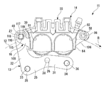
第1実施形態のディスクブレーキは、車両用、具体的には自動二輪車用のディスクブレーキである。図1〜図4に示すように、このディスクブレーキ11は、車体に固定されるキャリア13と、車輪に固定されたディスク12を跨ぐキャリパ14と、一対の摩擦パッド15,16と、パッドスプリング17と、図1〜図3に示すブーツ18と、図1に示すブーツ19とを有している。なお、各図に示す矢印Rは、車両の前進時のディスク12の回転方向を示しており、この回転方向における入口側をディスク回入側、出口側をディスク回出側として以下説明を行う。また、ディスク12の軸線方向をディスク軸方向、ディスク12の径方向をディスク径方向、ディスク12の回転方向をディスク回転方向またはディスク周方向とする。
The disc brake of the first embodiment is a disc brake for vehicles, specifically for motorcycles. As shown in FIGS. 1 to 4, the
ディスク12は円板状をなしており、ディスクブレーキ11の制動対象である車両の図示略の車輪に設けられて車輪とともに回転する。
The
キャリア13は、図1〜図4に示すマウンティングブラケット25と、マウンティングブラケット25に一体に固定される図3に示すガイドピン26と、マウンティングブラケット25に一体に固定される図1および図4に示すトルク受けピン27とを有している。
The
図1に示すように、マウンティングブラケット25は、ディスク12の一面側であるアウタ側(車輪とは反対側)に配置されて車両の非回転部に固定されるものである。マウンティングブラケット25は、図2および図4に示すように、ディスク回転方向に延在するベース部31と、ベース部31のディスク回入側の端部からディスク径方向外方に延出する径方向延出部32とを有している。ベース部31には、ディスク回入側の端部に取付穴33が、ディスク回出側に取付穴34が、それぞれディスク軸方向に貫通して形成されている。キャリア13は、マウンティングブラケット25において、取付穴33の周囲の固定部35と取付穴34の周囲の固定部36とが、取付穴33,34にそれぞれ螺合される図示略の取付ボルトで車両の非回転部に固定される。
As shown in FIG. 1, the
マウンティングブラケット25には、ベース部31のディスク回転方向の中間位置、言い換えれば取付穴33と取付穴34との間位置に、ガイドピン取付穴38が、ディスク軸方向に貫通して一カ所形成されている。また、マウンティングブラケット25には、径方向延出部32のディスク径方向外側の端部に図4に示すトルク受けピン取付穴39が、ディスク軸方向に貫通して一カ所形成されている。トルク受けピン取付穴39は、その中心がディスク12よりもディスク径方向外側に配置されている。また、トルク受けピン取付穴39はガイドピン取付穴38よりもディスク径方向外側かつディスク回入側に配置されている。
In the
マウンティングブラケット25は、例えば、金属製の板材からプレス成形で打ち抜かれることでその外形が形成され、これに、取付穴33,34、ガイドピン取付穴38およびトルク受けピン取付穴39が、切削加工等により形成されるものである。マウンティングブラケット25は、上記板材に対し、折り曲げ加工が行われることはなく、板厚方向に突起のない、厚さ一定のものとなっている。
The
ガイドピン26は、図3および図5に示すように、軸方向一端から順に、小径の固定軸部42と、固定軸部42より大径の中間軸部43と、中間軸部43より大径のフランジ部44と、中間軸部43よりも小径のガイド軸部45とを有している。ガイドピン26は、金属製であって、キャリア13において一本のみ設けられている。
As shown in FIGS. 3 and 5, the
ガイドピン26は、全体的にディスク12とは反対側(アウタ側)に突出するようにして、その固定軸部42がマウンティングブラケット25のガイドピン取付穴38に嵌合固定されている。このようにマウンティングブラケット25に取り付けられた状態で、ガイドピン26は、ディスク軸方向に沿って、マウンティングブラケット25からディスク12とは反対側に突出する。
The
トルク受けピン27は、図5に示すように、軸方向一端から順に、一定径の断面円形状のトルク受け軸部48と、トルク受け軸部48より大径の固定軸部(固定部)49と、固定軸部49より大径の中間軸部50と、中間軸部50より大径のフランジ部51と、固定軸部49よりも小径のガイド軸部52とを有している。トルク受けピン27は、金属製であって、キャリア13において一本のみ設けられている。
As shown in FIG. 5, the
トルク受けピン27は、固定軸部49がマウンティングブラケット25のトルク受けピン取付穴39に嵌合固定されている。このようにマウンティングブラケット25に取り付けられた状態で、トルク受けピン27は、その中心が、ディスク12よりも径方向外側に配置されており、ディスク軸方向に沿う状態で、一方のトルク受け軸部48側がディスク12側にディスク12を跨いで延出し、他方のガイド軸部52側がディスク12とは反対側に延出する。言い換えれば、トルク受けピン27は、マウンティングブラケット25からディスク12側およびディスク12とは反対側の両側に延出し、ディスク12の一面側であるアウタ側から、ディスク12の他面側であるインナ側までディスク12を越えて延出している。トルク受けピン取付穴39の形成位置によって、トルク受けピン27は、図6に示すように、キャリア13におけるディスク回入側に配置され、ガイドピン26よりもディスク回入側かつディスク径方向外側に配置されている。
The torque receiving
キャリパ14は、図1に示すように、トルク受けピン27のガイド軸部52と、図3に示すようにガイドピン26のガイド軸部45とで、キャリア13に対しディスク軸方向に摺動可能に支持されるものであり、いわゆるピンスライド型のキャリパとなっている。キャリパ14は、図2に示すように、キャリパボディ55と、二つのピストン56,57と、パッドピン58とを有している。
As shown in FIG. 1, the
キャリパボディ55は、アルミニウム合金等から鋳造により一体成形された後、切削加工されることで形成されるもので、図1〜図4に示すようにディスク12を跨いだ状態で、キャリア13の図1に示すトルク受けピン27および図3に示すガイドピン26に摺動可能に取り付けられている。キャリパボディ55は、キャリア13のアウタ側に配置されるシリンダ部62と、シリンダ部62のディスク径方向外側からディスク12の径方向外側を超えるようにインナ側に延出するブリッジ部63と、ブリッジ部63のインナ側の端部からシリンダ部62に対向するようにディスク12の径方向内側に延出する爪部64とを有している。
The
図2に示すように、シリンダ部62には、ディスク周方向の中間位置からディスク径方向内方に突出するようにして摺動案内部66が形成されており、また、ディスク径方向外側からディスク回入側に突出するようにして摺動案内部67が形成されている。摺動案内部66には、図3に示すガイドピン支持穴68がディスク軸方向に貫通して形成されており、摺動案内部67には、図1に示すトルク受けピン支持穴69がディスク12側からディスク軸方向の途中位置まで形成されている。
As shown in FIG. 2, a sliding
図3に示すように、シリンダ部62のガイドピン支持穴68には、上記したブーツ18が嵌合されており、摺動案内部66は、このブーツ18を介してガイドピン26のガイド軸部45に摺動可能に支持される。また、図1に示すように、シリンダ部62のトルク受けピン支持穴69には、トルク受けピン27のガイド軸部52が嵌合されており、摺動案内部67は、このトルク受けピン27のガイド軸部52に摺動可能に支持される。
なお、摺動案内部66及び摺動案内部67には、ガイド軸部45及びトルク受けピン27が内部に挿入されることで摺動案内するものであるが、これに限らず、摺動案内部66及び摺動案内部67をピン形状としてガイド軸部45及びトルク受けピン27の中心部に孔を設けて挿入するようにしてもよい。
As shown in FIG. 3, the above-described
Note that the sliding
ここで、図3に示すように、ブーツ18は、ゴム製であり、ガイドピン26の中間軸部43およびフランジ部44に係止される係止部72と、伸縮自在の蛇腹部73と、ガイドピン支持穴68に嵌合されるとともに内側に摺動穴74を有する筒状部75と、ガイド軸部45のフランジ部44とは反対側を覆う蓋部76とを有している。ブーツ18は、筒状部75でキャリパ14のガイドピン支持穴68に保持されるとともに、筒状部75の内側の摺動穴74にキャリア13のガイドピン26のガイド軸部45を摺動可能に嵌合させる。
Here, as shown in FIG. 3, the
図1に示すブーツ19も、ゴム製であり、トルク受けピン27の図5に示す中間軸部50およびフランジ部51に係止される図1に示す係止部80と、トルク受けピン支持穴69から突出するガイド軸部52を覆う伸縮自在の蛇腹部81とを有している。
The
以上により、キャリパボディ55は、キャリア13に設けられたガイドピン26およびトルク受けピン27によってディスク軸方向に沿う方向に摺動可能に支持されることになる。言い換えれば、トルク受けピン27は、キャリア16への固定部である固定軸部49からディスク軸方向でディスク12から離間する方向に延出してキャリパ14を摺動可能に支持する部位であるガイド軸部52を有する。
As described above, the
シリンダ部62には、爪部64側に向かって開口するようにディスク軸方向に沿って、図2に示すように二つの有底のボア87,88がディスク回転方向に並んで形成されている。ディスク回入側のボア87およびディスク回出側のボア88の間には、これらに連通する配管接続穴89がディスク径方向に沿って形成されており、この配管接続穴89に図示略のブレーキ配管が接続される。また、シリンダ部62のディスク回出側には、ボア88に連通するエア抜き用のブリーダプラグ90が取り付けられている。なお、図4に示すように、爪部64には、ボア87,88を加工する際に切削工具を通過させるためのリセス91,92がディスク径方向外方に凹む形状をなして、ディスク回入側とディスク回出側とに形成されている。
In the
図1に示すように、シリンダ部62のディスク軸方向のブリッジ部63側には、ディスク径方向外側においてディスク回出側にブリッジ部63よりも突出する回出側突出部95が形成されており、爪部64のディスク軸方向のブリッジ部63側にも、ディスク径方向外側においてディスク回出側にブリッジ部63よりも突出する回出側突出部96が形成されている。
As shown in FIG. 1, on the
ピストン56,57は、図2に示すように、シリンダ部62のボア87,88に摺動可能に嵌合される。この嵌合状態で、ピストン56,57は、キャリパボディ55に対しディスク回転方向に並んで配置される。ピストン56,57は、金属製となっている。
The
パッドピン58は、図1に示すように、キャリパボディ55の回出側突出部95および回出側突出部96に設けられたディスク軸方向に延びる貫通孔に嵌合されるものであり、この嵌合状態で回出側突出部95および回出側突出部96の間に配置される一定径の断面円形状のガイド軸部101を有している。パッドピン58は、金属製で、ディスク軸方向に沿っており、ガイド軸部101が、ディスク12よりもディスク径方向外側かつブリッジ部63よりもディスク回出側において、ディスク12を跨ぐように配置されている。ここで、キャリパボディ55が、ディスク軸方向に沿う方向に摺動可能となるようにキャリア13に支持された状態で、図7に示すパッドピン58の中心とトルク受けピン27の中心とを結ぶ線と、この線の中央位置とディスク12の中心(以下、ディスク中心と称す)とを結ぶ線とは、直交する。
As shown in FIG. 1, the
図1に示すように、一対の摩擦パッド15,16は、ディスク12の両面に配置されて、トルク受けピン27のトルク受け軸部48とパッドピン58のガイド軸部101とに支持されるものである。具体的には、摩擦パッド15が、ディスク12の一面側であるアウタ側に配置され、摩擦パッド16が、ディスク12の他面側であるインナ側に配置される。
As shown in FIG. 1, the pair of
図3に示すように、アウタ側の摩擦パッド15は、ディスク12に接触して摩擦抵抗を発生させる摩擦材106と、この摩擦材106を保持する金属製の板状の裏金107とを有している。
As shown in FIG. 3, the
摩擦パッド15の裏金107は、図5に示すように、摩擦材106がディスク12側の面に固着される主板部108と、図6に示すように、この主板部108のディスク径方向外側のディスク回入側から、ディスク回入側且つディスク径方向外側に斜めに突出する端部突出部109と、主板部108のディスク径方向外側のディスク回出側から、ディスク回出側且つディスク径方向外側に斜めに突出する端部突出部110とを有している。また、摩擦パッド15の裏金107は、主板部108のディスク径方向外縁の端部突出部109側から径方向外側に突出する突起部111と、主板部108のディスク径方向外縁の端部突出部110側から径方向外側に突出する突起部112とを有している。
As shown in FIG. 5, the
ディスク回入側の端部突出部109には、正方形状に近似する角が丸い多角形状の挿通孔115がディスク軸方向に貫通して形成されている。つまり、摩擦パッド15においては、ディスク回入側に挿通孔115が形成されている。挿通孔115は、ディスク径方向内側のディスク周方向中央(図中左右方向の中央部)にあってディスク軸方向に沿い且つ摩擦材106の中心(以下、パッド中心と称す)とディスク中心とを結ぶ線に直交する方向に沿う平面部116(図6中下側の平面部)と、ディスク径方向外側のディスク周方向中央にあってディスク軸方向に沿い且つパッド中心とディスク中心とを結ぶ線に直交する方向に沿う平面部117(図6中上側の平面部)と、ディスク回入側のディスク径方向中央にあってディスク軸方向に沿い且つパッド中心とディスク中心とを結ぶ線に沿う平面部118(図6中右側の平面部)と、ディスク回出側のディスク径方向中央にあってディスク軸方向に沿い且つパッド中心とディスク中心とを結ぶ線に沿う平面部119(図6中左側の平面部)とを有している。そして、この挿通孔115に、トルク受けピン27のトルク受け軸部48が挿通されることになるが、その際に、挿通孔115は、四カ所の平面部116〜119において円形状のトルク受け軸部48に当接可能となっている。
A
端部突出部110には、ディスク周方向に沿って長い係合孔(係合部)122がディスク軸方向に貫通して形成されている。つまり、摩擦パッド15において、挿通孔115以外の部位であるディスク回出側に係合孔122が形成されている。係合孔122は、ディスク径方向内側にあってディスク軸方向に沿い且つパッド中心とディスク中心とを結ぶ線に直交する方向に沿う平面部123(図6中下側の平面部)と、ディスク径方向外側にあってディスク軸方向に沿い且つパッド中心とディスク中心とを結ぶ線に直交する方向に沿う平面部124(図6中上側の平面部)と、ディスク回入側にあってディスク軸方向に沿う半円状をなす湾曲面部125(図6中右側の曲面部)と、ディスク回出側にあってディスク軸方向に沿う半円状をなす湾曲面部126(図6中左側の曲面部)とを有している。そして、この係合孔122に、パッドピン58のガイド軸部101が挿通されることになり、その際に、平面部123と、これに平行をなす面部124とが、円形状のパッドピン58の円形状のガイド軸部101に対し当接可能となっている。また、係合孔122は、湾曲面部125,126が、パッドピン58に当接しないように、係合孔122とパッドピン58とには、ディスク回転方向両側に所定の隙間が設けられている。なお、この隙間は、少なくともディスク回入側のみ設けられていれば良い。トルク受けピン27およびパッドピン58に支持された状態で、一対の摩擦パッド15,16は、係合孔122の中心と挿通孔115の中心とを結ぶ線が、パッド中心とディスク中心とを結ぶ線に直交する方向に沿っている。
The
ここで、図7に示すように、係合孔122は、摩擦パッド15において、トルク受けピン27の中心と、摩擦パッド15の周方向長さの中心との距離のほぼ2倍の距離だけトルク受けピン27の中心から離れた位置に形成されている。具体的に、摩擦パッド15は、そのディスク周方向の長さの中心が、挿通孔115と係合孔122とを結ぶ線分の中心と、ディスク周方向の位置が一致している。
Here, as shown in FIG. 7, the
以上により、アウタ側の摩擦パッド15は、ディスク回入側に形成された挿通孔115が、キャリア13のトルク受けピン27のトルク受け軸部48に摺動可能に支持されるとともに、ディスク回出側に形成された係合孔122が、パッドピン58のガイド軸部101に支持され、これらトルク受け軸部48およびガイド軸部101でディスク軸方向の摺動が案内される。なお、摩擦パッド15は、突起部111,112にて図3に示すパッドスプリング17に当接することになり、パッドスプリング17でディスク径方向内側かつディスク回出側に斜めに付勢される。
As described above, the
インナ側の摩擦パッド16は、アウタ側の摩擦パッド15に対し、ディスク12を介して鏡面対象をなしている。
The
つまり、インナ側の摩擦パッド16には、アウタ側の摩擦パッド15と共通の裏金107が用いられ、この裏金107に対し、アウタ側の摩擦パッド15と共通の摩擦材106を、表裏逆向側に固着して構成されている。つまり、裏金107は、アウタ側の摩擦パッド15とインナ側の摩擦パッド16とで共通化された共用部品となっている。
That is, the inner
これにより、インナ側の摩擦パッド16の裏金107も、主板部108のディスク12側の面に摩擦材106が固着されることになり、図6に示すように、この主板部108からディスク回入側に突出する端部突出部109に挿通孔115が形成され、主板部108からディスク回出側に突出する端部突出部110に係合孔122が形成され、主板部108から径方向外側にそれぞれ突出する突起部111,112が形成された形状をなしている。
As a result, the
インナ側の摩擦パッド16も、ディスク回入側に形成された挿通孔115に、平面部116〜119に当接可能となるように、アウタ側の摩擦パッド15を支持するものと同一のトルク受けピン27の円形状のトルク受け軸部48が挿通されることになり、挿通孔115以外の部位であるディスク回出側に形成された係合孔122に、平面部123,124に当接可能となるように、アウタ側の摩擦パッド15を支持するものと同一のパッドピン58の円形状のガイド軸部101がディスク回転方向両側に所定の隙間を形成しつつ挿通されることになる。一つのトルク受けピン27は、一対の摩擦パッド15,16が摺動する部位であるトルク受け軸部48が、円形状となっている。
The
摩擦パッド16においても、図7に示すように、係合孔122は、トルク受けピン27の中心と、摩擦パッド16の周方向長さの中心との距離のほぼ2倍の距離だけトルク受けピン27の中心から離れた位置に形成されている。具体的に、摩擦パッド16は、そのディスク周方向の長さの中心が、挿通孔115と係合孔122とを結ぶ線分の中心と、ディスク周方向の位置が一致している。
Also in the
以上により、このインナ側の摩擦パッド16も、ディスク回入側に形成された挿通孔115が、キャリア13のトルク受けピン27のトルク受け軸部48に摺動可能に支持されるとともに、ディスク回出側の係合孔122が、パッドピン58のガイド軸部101に支持され、これらトルク受けピン27およびパッドピン58でディスク軸方向の摺動が案内される。また、インナ側の摩擦パッド16の裏金107も、突起部111,112がパッドスプリング17でディスク径方向内側かつディスク回出側に斜めに付勢される。
As described above, the
また、キャリア13には、ディスク回入側に、一対の摩擦パッド15,16が摺動する一つのトルク受けピン27が設けられており、一対の摩擦パッド15,16には、それぞれのディスク回入側にトルク受けピン27が挿通する挿通孔115が形成され、また、挿通孔115以外の部位にキャリパ14に係合する係合部である係合孔122が形成されている。なお、アウタ側の摩擦パッド15およびインナ側の摩擦パッド16は、両方とも、マウンティングブラケット25には支持されておらず、マウンティングブラケット25に取り付けられたトルク受けピン27およびキャリパ14に取り付けられたパッドピン58のみに支持されている。そして、インナ側の摩擦パッド16のディスク12とは反対側に、キャリパ14の爪部64が配置され、アウタ側の摩擦パッド15のディスク12とは反対側に、キャリパ14のシリンダ部62が配置されることになる。
Further, the
以上の構成のディスクブレーキ11においては、車両前進時に、図示せぬブレーキ配管からキャリパ14のシリンダ部62の配管接続穴89を介してボア87,88内にブレーキ液が導入されると、このブレーキ液圧によってピストン56,57が爪部64側に前進する。すると、ピストン56,57がディスク軸方向でディスク12側に突出して、一対の摩擦パッド15,16のうち一方であるアウタ側の摩擦パッド15を押圧する。これにより、アウタ側の摩擦パッド15が、トルク受けピン27のガイド軸部101およびパッドピン58のトルク受け軸部48を摺動してディスク12に接触することになる。一方、その反力で、キャリパボディ55が、爪部64をディスク12側に移動させるようにガイドピン26のガイド軸部45およびトルク受けピン27のガイド軸部52を摺動してインナ側の摩擦パッド16を押圧する。これにより、インナ側の摩擦パッド16が、トルク受けピン27のガイド軸部101およびパッドピン58のトルク受け軸部48を摺動してディスク12に接触することになる。このようにして、ディスク12の両面に設けられた一対の摩擦パッド15,16をディスク12に接触させ、その摩擦抵抗により、ディスク12つまり車輪を制動する。
In the
そして、上記車両前進時の制動中に、一対の摩擦パッド15,16にはディスク回入側からディスク回出側に制動トルクが発生することになり、このディスク回転方向の制動トルクをディスク回入側の一つのトルク受けピン27が、これに当接する挿通孔115の平面部117,118から受けることになる。これに対し、キャリパ14のパッドピン58は、一対の摩擦パッド15,16を、共にディスク回転方向に長い係合孔122で支持しており、係合孔122とパッドピン58とには、ディスク回転方向に所定の隙間が設けられていて、一対の摩擦パッド15,16から制動トルクを受けないようになっている。つまり、このディスクブレーキ11は、制動中の制動トルクをディスク回入側で受けるプル式のディスクブレーキとなっており、車両前進時の制動中に一対の摩擦パッド15,16に生じた制動トルクを、ディスク回入側の一つのトルク受けピン27のみが受けることになる。
During braking when the vehicle is moving forward, braking torque is generated from the disk entry side to the disk delivery side on the pair of
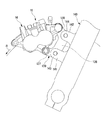
ここで、ディスクブレーキ11は、図8に示すように、二輪車の後上がりに傾斜するフロントフォーク130の後部の下側および上側の二カ所のキャリパサポート131,132の後端の取付部133,134に上記したキャリア13の固定部35,36においてボルト止めされ、フロントフォーク130の後方に配置されることになる。取付部133,134を含むキャリパサポート131,132は、車輪のように回転しない車両の非回転部となっている。
Here, as shown in FIG. 8, the
なお、図9に示すように、ベース部136と、ベース部136の両端から同方向に延出する延出部137,138とを有するコ字状のキャリア139を用いて、このキャリア139の延出部137,138のそれぞれの先端にガイドピン26およびトルク受けピン27を設け、ベース部136の両端を、フロントフォーク140の前部の二カ所のキャリパサポート141,142の先端の取付部143,144にボルト止めするようにしても良い。この場合、小型のキャリア139とすることができる。
As shown in FIG. 9, a
ここで、上記した特許文献1記載のディスクブレーキにおいては、キャリパを支持するキャリアの車両前進時のディスク回入側にT字状の溝を形成し、この溝に摩擦パッドのT字状の突起を係合させて、制動時に摩擦パッドに生じるトルクをキャリアのT字状の溝で受ける構造となっている。このように制動トルクをディスク回入側で受けるものにおいては、ディスク回入側の面圧低下により制動中の面圧を均一化でき、これにより、ブレーキ鳴きの抑制性能が向上する。しかしながら、キャリアのT字状の溝で制動トルクを受ける構造であると、溝の形状および摩擦パッドの突起の形状が複雑であり、生産性が良くないという問題があった。また、制動時の摩擦パッドの面圧が安定しないため、摩擦パッドが偏摩耗したり、ブレーキ鳴きを生じたりするという問題もあった。 Here, in the above-described disc brake described in Patent Document 1, a T-shaped groove is formed on the disk insertion side of the carrier supporting the caliper when the vehicle advances, and the T-shaped protrusion of the friction pad is formed in this groove. And the torque generated in the friction pad during braking is received by the T-shaped groove of the carrier. In this way, in the case where the braking torque is received on the disk insertion side, the surface pressure during braking can be made uniform due to the decrease in the surface pressure on the disk insertion side, thereby improving the brake noise suppression performance. However, the structure that receives the braking torque by the T-shaped groove of the carrier has a problem that the shape of the groove and the shape of the protrusion of the friction pad are complicated, and the productivity is not good. Further, since the surface pressure of the friction pad during braking is not stable, there is a problem that the friction pad wears unevenly or brake noise is generated.
第1実施形態のディスクブレーキ11によれば、キャリア13のディスク回入側に配置された一つのトルク受けピン27で、一対の摩擦パッド15,16を摺動させることになり、この一つのトルク受けピン27が、車両前進時の制動中に一対の摩擦パッド15,16に発生するディスク回転方向の制動トルクを受けることになる。よって、制動トルクをディスク回入側で受けることから、セルフサーボ効果が発生しないため、制動中の摩擦パッド15,16のディスク回入側の面圧を低下でき、面圧の均一化が図れる。これにより、摩擦パッド15,16の偏摩耗を低減できるため、摩擦パッド15,16の長寿命化、ブレーキ操作量の低減およびブレーキ操作フィーリングの向上を図ることができる。また、ブレーキ鳴きを抑制できる。
According to the
また、一つのトルク受けピン27が、車両前進時の制動中に一対の摩擦パッド15,16に発生するディスク回転方向の制動トルクを受けることになるため、構造が簡素となり、生産性を向上させることができる。特に、キャリア13のマウンティングブラケット25にトルク受け部を形成する必要がなくなるため、マウンティングブラケット25の形状を簡素化でき、生産性を向上させることができる。
Further, since one
また、両摩擦パッド15,16で裏金107を共通化できるため、部品の種類を削減することができ、製造コストおよび管理コストを低減できる。
In addition, since the
また、キャリパ14に支持されるパッドピン58と、一対の摩擦パッド15,16のそれぞれのディスク回出側に形成された係合孔122とに、車両前進時の制動トルクを受けないようにディスク回転方向に所定の隙間が設けられているため、パッドピン58は摩擦パッド15,16を支持するものとなってその役割が明確化されるため、パッドピン58を含むキャリパ14を小型化および簡素化することができる。
Further, the disc rotation is performed so that the
また、係合孔122が、一対の摩擦パッド15,16のそれぞれに、トルク受けピン27の中心と摩擦パッド15,16の周方向の中心との距離のほぼ2倍の距離だけトルク受けピン27の中心から離れた位置に形成されているため、摩擦パッド15,16の全体を小型化しつつパッドピン58への負荷を軽減し、パッドピン58の小型化を図ることができる。
Further, the
また、一つのトルク受けピン27は、円形状の部位であるトルク受け軸部48で一対の摩擦パッド15,16の制動トルクを受けるため、上記のように摩擦パッド15,16の全体を小型化しつつパッドピン58への負荷を軽減しパッドピン58の小型化を図ることが、容易にできる。
Since one
つまり、上記ディスクブレーキ11は、図7に示すように、トルク受けピン27がディスク回入側に配置されたプル式であり、トルク受けピン27のトルク受け軸部48が丸断面であり、摩擦パッド15,16に加わる力Fの方向とトルク受けピン27に加わる力Ftの方向とのなす角αと、力Fの方向と力Ftと直交する方向の分力Fdの方向とのなす角βとの関係がα<βであり、トルク受けピン27の中心とパッド中心Oとの距離Ldと、トルク受けピン27の中心とパッドピン58の中心との距離Lpとの関係がLd<Lpであり、パッドスプリング17による突起部111,112の押圧による力Fsの方向が同方向である、という条件を満たすことになる。
That is, as shown in FIG. 7, the
これらの条件を満たす場合に、トルク受けピン27には、上記力Ftがかかるのみであり、モーメントは作用しないため、トルク受けピン27および挿通孔115への負荷が少ない。また、パッドピン58には、ディスク径方向内側に力Fpがかかることになり、幾何学的な条件から、力Ftと力Fpとの関係は、Ft>>Fpである。これにより、パッドピン58を小型化および簡素化することができる。また、パッドスプリング17による突起部111,112を押圧する力Fsは、パッドピン58による力Fpとほぼ同方向であるため、トルク受けピン27回りのモーメントM2を発生するために必要な力Fpはさらに小さくて良い。これにより、さらにパッドピン58を小型化および簡素化することができる。そして、摩擦パッド15,16の全体を小型化しつつパッドピン58への負荷軽減(小型化)を図るためには、Lp:Ld=2:1が望ましい。つまり、係合孔122が、一対の摩擦パッド15,16のそれぞれに、トルク受けピン27の中心と摩擦パッド15,16の周方向の中心との距離のほぼ2倍の距離だけトルク受けピン27の中心から離れた位置に形成されているのが良い。
When these conditions are satisfied, only the force Ft is applied to the
一対の摩擦パッド15,16は、ディスク周方向の中心が、トルク受けピン27が挿通する挿通孔115と、パッドピン58が挿通する係合孔122とを結ぶ線分の中心と、ディスク周方向の位置が一致しているため、摩擦パッド15,16の全体を小型化しつつパッドピン58への負荷を軽減し、パッドピン58の小型化を図ることができる。
The pair of
また、一つのトルク受けピン27は、キャリア13への固定部である固定軸部49から、ディスク12を跨いでディスク軸方向に延出して一対の摩擦パッド15,16の制動トルクを受けるトルク受け軸部48とは反対に、ディスク軸方向でディスク12から離間する方向に延出する部位であるガイド軸部52で、キャリパ14を摺動可能に支持するため、制動トルクの影響を抑制しつつトルク受けピン27でキャリパ14を摺動可能に支持することができる。したがって、構造がさらに簡素となり、生産性をさらに向上させることができる。
Further, one
「第2実施形態」
次に、第2実施形態を主に図10および図11に基づいて第1実施形態との相違部分を中心に説明する。なお、第1実施形態と共通する部位については、同一称呼、同一の符号で表す。
“Second Embodiment”
Next, the second embodiment will be described mainly on the difference from the first embodiment based on FIGS. In addition, about the site | part which is common in 1st Embodiment, it represents with the same name and the same code | symbol.
第2実施形態においては、キャリパ14に、第1実施形態のパッドピン58は設けられておらず、回出側突出部95にディスク軸方向に沿ってディスク12側に突出する摺動台部150が形成され、回出側突出部96にディスク軸方向に沿ってディスク12側に突出する摺動台部151が形成されている。
In the second embodiment, the
また、摩擦パッド15,16の共通の裏金107の端部突出部110に、キャリパ14の摺動台部150,151に係合する係合部152が形成されている。そして、この係合部152が摺動台部150,151上をそのディスク径方向外側に沿って摺動することになり、その結果、摩擦パッド15,16が回り止めされて摺動するようになっている。つまり、一対の摩擦パッド15,16は、それぞれのディスク回入側にトルク受けピン27が挿通する挿通孔115が形成され、挿通孔115以外の部位にキャリパ14に係合する係合部152が形成されている。
Further, an engaging
このような第2実施形態によれば、パッドピンが不要となるため部品点数および製造コストを低減できる。 According to such 2nd Embodiment, since a pad pin becomes unnecessary, a number of parts and manufacturing cost can be reduced.
上記実施の形態のディスクブレーキによれば、車両の非回転部に固定されるキャリアと、該キャリアに摺動可能に支持されディスクの両面に配置される一対の摩擦パッドと、該一対の摩擦パッドのうち一方の摩擦パッドを押圧するピストンを有し前記キャリアに摺動可能に支持されるキャリパとを有するディスクブレーキにおいて、前記キャリアには、車両前進時のディスク回入側に配置され、前記ディスクを跨いでディスク軸方向に延出し、前記一対の摩擦パッドが摺動する一つのトルク受けピンが設けられ、前記一対の摩擦パッドは、それぞれの前記ディスク回入側に前記トルク受けピンが挿通する挿通孔が形成され、また、前記挿通孔以外の部位に前記キャリパに係合する係合部が形成され、前記ディスク回入側の一つのトルク受けピンは、前記車両前進時の制動中に前記一対の摩擦パッドに発生するディスク回転方向の制動トルクを受けることを特徴とする。このように、キャリアのディスク回入側に配置された一つのトルク受けピンで、一対の摩擦パッドを摺動させることになり、この一つのトルク受けピンが、車両前進時の制動中に一対の摩擦パッドに発生するディスク回転方向の制動トルクを受けることになる。よって、制動時のトルクをディスク回入側で受けることから、セルフサーボ効果が発生しないため、制動中の摩擦パッドのディスク回入側の面圧を低下でき面圧の均一化が図れる。これにより、摩擦パッドの偏摩耗を低減できるため、摩擦パッドの長寿命化、ブレーキ操作量の低減およびブレーキ操作フィーリングの向上を図ることができる。また、ブレーキ鳴きを抑制できる。加えて、一つのトルク受けピンが、車両前進時の制動中に一対の摩擦パッドに発生するディスク回転方向の制動トルクを受けることになるため、構造が簡素となり、生産性を向上させることができる。特に、キャリアのマウンティングブラケットにトルク受け部を形成する必要がなくなるため、マウンティングブラケットの形状を簡素化でき、生産性を向上させることができる。両摩擦パッドで裏金を共通化できるため、部品の種類を削減することができ、製造コストおよび管理コストを低減できる。 According to the disc brake of the above embodiment, the carrier fixed to the non-rotating part of the vehicle, the pair of friction pads slidably supported by the carrier and disposed on both sides of the disc, and the pair of friction pads A disc brake having a piston that presses one of the friction pads and a caliper that is slidably supported by the carrier, wherein the carrier is disposed on a disc entry side when the vehicle moves forward, and the disc across extend the disk axis direction, the pair of friction pads one torque receiving pin is provided with a slide, said pair of friction pads are left said torque receiving pin on each of the disk rotation entrance side An insertion hole for insertion is formed, and an engaging portion for engaging with the caliper is formed at a portion other than the insertion hole, and one torque receiving pin on the disk insertion side is formed. It is characterized by receiving the braking torque of the disk rotational direction generated in the pair of friction pad during braking when the vehicle travels forward. In this way, a pair of friction pads are slid with a single torque receiving pin arranged on the disk insertion side of the carrier, and this single torque receiving pin is used as a pair during braking when the vehicle moves forward. The braking torque generated in the friction pad in the disk rotation direction is received. Therefore, since the torque at the time of braking is received on the disk feed-in side, the self-servo effect does not occur, so the surface pressure on the disk feed-in side of the friction pad during braking can be reduced and the surface pressure can be made uniform. Accordingly, uneven wear of the friction pad can be reduced, so that the life of the friction pad can be extended, the amount of brake operation can be reduced, and the brake operation feeling can be improved. Moreover, brake squeal can be suppressed. In addition, since one torque receiving pin receives a braking torque in the disk rotation direction generated in the pair of friction pads during braking when the vehicle moves forward, the structure is simplified and productivity can be improved. . In particular, since it is not necessary to form a torque receiving portion on the mounting bracket of the carrier, the shape of the mounting bracket can be simplified and productivity can be improved. Since the back metal can be shared by both friction pads, the types of parts can be reduced, and the manufacturing cost and the management cost can be reduced.
また、前記係合部は、前記一対の摩擦パッドのそれぞれの車両前進時のディスク回出側に形成され、前記キャリパに支持されるパッドピンが挿通する係合孔であり、該係合孔と前記パッドピンとは、車両前進時の制動トルクを受けないようにディスク回転方向に所定の隙間が設けられていることを特徴とする。このように、キャリパに支持されるパッドピンと、一対の摩擦パッドのそれぞれのディスク回出側に形成された係合孔とに、車両前進時の制動トルクを受けないようにディスク回転方向に所定の隙間が設けられているため、パッドピンは摩擦パッドを支持するものとなってその役割が明確化されるため、パッドピンを含むキャリパを小型化および簡素化することができる。 The engagement portion is an engagement hole formed on the disk delivery side of each of the pair of friction pads when the vehicle advances, and through which a pad pin supported by the caliper is inserted. The pad pin is characterized in that a predetermined gap is provided in the disk rotation direction so as not to receive a braking torque when the vehicle moves forward. In this way, the pad pin supported by the caliper and the engagement holes formed on the respective disk delivery sides of the pair of friction pads have a predetermined disc rotation direction so as not to receive braking torque when the vehicle moves forward. Since the gap is provided, the pad pin supports the friction pad and its role is clarified. Therefore, the caliper including the pad pin can be reduced in size and simplified.
また、前記係合部は、前記一対の摩擦パッドのそれぞれに、前記トルク受けピンの中心と前記摩擦パッドの周方向の中心との距離のほぼ2倍の距離だけ前記トルク受けピンの中心から離れた位置に形成され、前記キャリパに支持されるパッドピンが挿通する係合孔であることを特徴とする。このように、係合部が、一対の摩擦パッドのそれぞれに、トルク受けピンの中心と摩擦パッドの周方向の中心との距離のほぼ2倍の距離だけトルク受けピンの中心から離れた位置に形成されているため、摩擦パッドの全体を小型化しつつパッドピンへの負荷を軽減し、パッドピンの小型化を図ることができる。 Further, the engaging portion is separated from the center of the torque receiving pin by a distance of approximately twice the distance between the center of the torque receiving pin and the circumferential center of the friction pad. The engagement hole is formed in a position where the pad pin supported by the caliper is inserted. In this way, the engaging portion is located at a position away from the center of the torque receiving pin by a distance that is approximately twice the distance between the center of the torque receiving pin and the center of the friction pad in the circumferential direction. Since it is formed, it is possible to reduce the load on the pad pin while reducing the size of the entire friction pad, and to reduce the size of the pad pin.
また、前記一対の摩擦パッドは、ディスク周方向の中心が、前記挿通孔と前記係合孔とを結ぶ線分の中心と、ディスク周方向の位置が一致していることを特徴とする。このように、一対の摩擦パッドは、ディスク周方向の中心が、トルク受けピンが挿通する挿通孔と、パッドピンが挿通する係合孔とを結ぶ線分の中心と、ディスク周方向の位置が一致しているため、摩擦パッドの全体を小型化しつつパッドピンへの負荷を軽減し、パッドピンの小型化を図ることができる。 Further, the pair of friction pads is characterized in that the center in the disk circumferential direction coincides with the center of a line segment connecting the insertion hole and the engagement hole in the disk circumferential direction. As described above, the pair of friction pads has a center in the disk circumferential direction, and the center of the line segment connecting the insertion hole through which the torque receiving pin is inserted and the engagement hole through which the pad pin is inserted, and the position in the disk circumferential direction are the same. Therefore, it is possible to reduce the load on the pad pin while reducing the size of the entire friction pad and to reduce the size of the pad pin.
また、前記一つのトルク受けピンは、前記一対の摩擦パッドが摺動する部位が、円形状となっていることを特徴とする。このように、一つのトルク受けピンは、円形状の部位で一対の摩擦パッドの制動トルクを受けるため、上記のように摩擦パッドの全体を小型化しつつパッドピンへの負荷を軽減しパッドピンの小型化を図ることが、容易にできる。 The one torque receiving pin is characterized in that a portion where the pair of friction pads slide is circular. Thus, since one torque receiving pin receives the braking torque of a pair of friction pads at a circular portion, the load on the pad pin is reduced and the pad pin is reduced in size while reducing the size of the entire friction pad as described above. Can be easily achieved.
また、前記トルク受けピンは、前記キャリアへの固定部からディスク軸方向で前記ディスクから離間する方向に延出して前記キャリパを摺動可能に支持する部位を有することを特徴とする。このように、トルク受けピンは、キャリアへの固定部から、ディスクを跨いでディスク軸方向に延出して一対の摩擦パッドの制動トルクを受ける部位とは反対に、ディスク軸方向でディスクから離間する方向に延出する部位で、キャリパを摺動可能に支持するため、制動トルクの影響を抑制しつつトルク受けピンでキャリパを摺動可能に支持することができる。したがって、構造がさらに簡素となり、生産性をさらに向上させることができる。 Further, the torque receiving pin has a portion that extends in a direction away from the disk in a disk axial direction from a fixing portion to the carrier and slidably supports the caliper. In this manner, the torque receiving pin is separated from the disk in the disk axial direction, as opposed to the portion receiving the braking torque of the pair of friction pads extending from the fixing portion to the carrier across the disk in the disk axial direction. Since the caliper is slidably supported at the portion extending in the direction, the caliper can be slidably supported by the torque receiving pin while suppressing the influence of the braking torque. Therefore, the structure is further simplified and the productivity can be further improved.
11 ディスクブレーキ
12 ディスク
13 キャリア
14 キャリパ
15,16 摩擦パッド
27 トルク受けピン
48 トルク受け軸部(摩擦パッドが摺動する部位)
49 固定軸部(固定部)
52 ガイド軸部(キャリパを摺動可能に支持する部位)
56,57 ピストン
58 パッドピン
115 挿通孔
122 係合孔(係合部)
131,132,141,142 キャリパサポート(非回転部)
152 係合部
DESCRIPTION OF
49 Fixed shaft (fixed part)
52 Guide shaft (site that supports caliper slidably)
56, 57
131, 132, 141, 142 Caliper support (non-rotating part)
152 engaging part
Claims (7)
前記キャリアには、車両前進時のディスク回入側に配置され、前記ディスクを跨いでディスク軸方向に延出し、前記一対の摩擦パッドが摺動するトルク受けピンが一本のみ設けられ、
前記一対の摩擦パッドは、それぞれの前記ディスク回入側に前記トルク受けピンが挿通する挿通孔が形成され、
前記挿通孔以外の部位に前記キャリパの被係合部に係合する係合部が形成され、
前記一つのトルク受けピンは、前記車両前進時の制動中に前記一対の摩擦パッドに発生するそれぞれのディスク回転方向の制動トルクを受けるものであり、
前記被係合部は、前記車両前進時の制動中に前記一対の摩擦パッドに発生するそれぞれのディスク径方向内側にかかる制動トルクを受けるものであり、
前記一対の摩擦パッドは、前記トルク受けピンと前記被係合部のみに支持されていることを特徴とするディスクブレーキ。 A carrier fixed to a non-rotating portion of the vehicle; a pair of friction pads supported on the carrier so as to be slidable; and a piston that presses one of the friction pads; In a disc brake having a caliper that is slidably supported by the carrier,
The carrier is disposed on the disk entrance side when the vehicle moves forward, extends in the disk axial direction across the disk, and is provided with only one torque receiving pin on which the pair of friction pads slide,
The pair of friction pads are formed with insertion holes through which the torque receiving pins are inserted on the respective disk insertion sides,
Engaging portion engaged with the engaged portion of said caliper is formed at a portion other than the previous SL insertion hole,
The one torque receiving pin receives a braking torque in each disk rotation direction generated in the pair of friction pads during braking when the vehicle moves forward ,
The engaged portion receives a braking torque applied to each inner side in the disk radial direction generated in the pair of friction pads during braking when the vehicle moves forward.
The pair of friction pads are supported by only the torque receiving pin and the engaged portion .
Priority Applications (3)
| Application Number | Priority Date | Filing Date | Title |
|---|---|---|---|
| JP2010276191A JP5879032B2 (en) | 2010-12-10 | 2010-12-10 | Disc brake |
| PCT/JP2011/078434 WO2012077754A1 (en) | 2010-12-10 | 2011-12-08 | Disc brake |
| CN201180047646.XA CN103249959B (en) | 2010-12-10 | 2011-12-08 | Disc-brake |
Applications Claiming Priority (1)
| Application Number | Priority Date | Filing Date | Title |
|---|---|---|---|
| JP2010276191A JP5879032B2 (en) | 2010-12-10 | 2010-12-10 | Disc brake |
Publications (3)
| Publication Number | Publication Date |
|---|---|
| JP2012122598A JP2012122598A (en) | 2012-06-28 |
| JP2012122598A5 JP2012122598A5 (en) | 2014-01-16 |
| JP5879032B2 true JP5879032B2 (en) | 2016-03-08 |
Family
ID=46207237
Family Applications (1)
| Application Number | Title | Priority Date | Filing Date |
|---|---|---|---|
| JP2010276191A Expired - Fee Related JP5879032B2 (en) | 2010-12-10 | 2010-12-10 | Disc brake |
Country Status (3)
| Country | Link |
|---|---|
| JP (1) | JP5879032B2 (en) |
| CN (1) | CN103249959B (en) |
| WO (1) | WO2012077754A1 (en) |
Families Citing this family (3)
| Publication number | Priority date | Publication date | Assignee | Title |
|---|---|---|---|---|
| ITUA20162181A1 (en) * | 2016-03-31 | 2017-10-01 | Freni Brembo Spa | TABLETS, SETS, CALIPER AND METHOD FOR DISC BRAKE |
| JP6493309B2 (en) * | 2016-05-31 | 2019-04-03 | 株式会社アドヴィックス | Brake caliper |
| TWI715264B (en) * | 2018-12-26 | 2021-01-01 | 日商本田技研工業股份有限公司 | Disc brake and its manufacturing method |
Family Cites Families (8)
| Publication number | Priority date | Publication date | Assignee | Title |
|---|---|---|---|---|
| JPS589005Y2 (en) * | 1977-03-03 | 1983-02-18 | 日信工業株式会社 | motorcycle disc brake device |
| JPS5732231A (en) * | 1980-08-01 | 1982-02-20 | Baruresutora Chiimika Spa | Membrane type sulfonation and improved process for multi stage nutralization of sulfonic acid and device therefor |
| JPS6314029U (en) * | 1986-07-11 | 1988-01-29 | ||
| US5499696A (en) * | 1993-07-27 | 1996-03-19 | Tokico Ltd. | Disk brake |
| JPH07127674A (en) * | 1993-11-05 | 1995-05-16 | Nissin Kogyo Kk | Vehicle disc brake |
| JPH07208514A (en) * | 1994-01-19 | 1995-08-11 | Tokico Ltd | Disc brake |
| JP2008196683A (en) * | 2006-06-29 | 2008-08-28 | Akebono Brake Ind Co Ltd | Disc brake |
| WO2010010583A1 (en) * | 2008-07-22 | 2010-01-28 | Freni Brembo S.P.A. | Pad for a brake caliper and brake caliper for a disc brake |
-
2010
- 2010-12-10 JP JP2010276191A patent/JP5879032B2/en not_active Expired - Fee Related
-
2011
- 2011-12-08 WO PCT/JP2011/078434 patent/WO2012077754A1/en active Application Filing
- 2011-12-08 CN CN201180047646.XA patent/CN103249959B/en not_active Expired - Fee Related
Also Published As
| Publication number | Publication date |
|---|---|
| CN103249959B (en) | 2017-03-08 |
| JP2012122598A (en) | 2012-06-28 |
| WO2012077754A1 (en) | 2012-06-14 |
| CN103249959A (en) | 2013-08-14 |
Similar Documents
| Publication | Publication Date | Title |
|---|---|---|
| JP6208065B2 (en) | Opposite piston type disc brake device | |
| JP5847561B2 (en) | Disc brake | |
| JP5368528B2 (en) | Mechanical disc brake for stationary | |
| CN101852256B (en) | Disc brake apparatus | |
| JP2006057718A (en) | Floating calliper type disk brake | |
| US20180106310A1 (en) | Disc brake device | |
| JP5879032B2 (en) | Disc brake | |
| US8708111B2 (en) | Disk brake equipped reduced-size yoke | |
| JP3939304B2 (en) | Floating caliper type disc brake | |
| JP2014101998A (en) | Disc brake device | |
| JP2016028215A (en) | Disc brake | |
| JP5826091B2 (en) | Disc brake | |
| JP5587876B2 (en) | Caliper body support structure for vehicle disc brakes | |
| JP2009133356A (en) | Floating caliper type disc brake | |
| WO2010137715A1 (en) | Disc brake for vehicles | |
| JP4857203B2 (en) | Disc brake | |
| TWI703281B (en) | Disc brake | |
| JP4802172B2 (en) | Disc brake | |
| JP5677581B2 (en) | Disc brake | |
| JP4249065B2 (en) | Disc brake | |
| JP2012167739A (en) | Disk brake | |
| JP6134613B2 (en) | Disc brake | |
| JP4955095B2 (en) | Vehicle disc brake | |
| JP2010112424A (en) | Opposed piston type disk brake | |
| JP2009180265A (en) | Disc brake |
Legal Events
| Date | Code | Title | Description |
|---|---|---|---|
| A521 | Request for written amendment filed |
Free format text: JAPANESE INTERMEDIATE CODE: A523 Effective date: 20131125 |
|
| A621 | Written request for application examination |
Free format text: JAPANESE INTERMEDIATE CODE: A621 Effective date: 20131125 |
|
| A131 | Notification of reasons for refusal |
Free format text: JAPANESE INTERMEDIATE CODE: A131 Effective date: 20141104 |
|
| A521 | Request for written amendment filed |
Free format text: JAPANESE INTERMEDIATE CODE: A523 Effective date: 20141224 |
|
| A131 | Notification of reasons for refusal |
Free format text: JAPANESE INTERMEDIATE CODE: A131 Effective date: 20150529 |
|
| A521 | Request for written amendment filed |
Free format text: JAPANESE INTERMEDIATE CODE: A523 Effective date: 20150728 |
|
| TRDD | Decision of grant or rejection written | ||
| A01 | Written decision to grant a patent or to grant a registration (utility model) |
Free format text: JAPANESE INTERMEDIATE CODE: A01 Effective date: 20160105 |
|
| A61 | First payment of annual fees (during grant procedure) |
Free format text: JAPANESE INTERMEDIATE CODE: A61 Effective date: 20160201 |
|
| R150 | Certificate of patent or registration of utility model |
Ref document number: 5879032 Country of ref document: JP Free format text: JAPANESE INTERMEDIATE CODE: R150 |
|
| R250 | Receipt of annual fees |
Free format text: JAPANESE INTERMEDIATE CODE: R250 |
|
| LAPS | Cancellation because of no payment of annual fees |