JP6203935B2 - Addition comparison selection instruction - Google Patents
Addition comparison selection instruction Download PDFInfo
- Publication number
- JP6203935B2 JP6203935B2 JP2016501437A JP2016501437A JP6203935B2 JP 6203935 B2 JP6203935 B2 JP 6203935B2 JP 2016501437 A JP2016501437 A JP 2016501437A JP 2016501437 A JP2016501437 A JP 2016501437A JP 6203935 B2 JP6203935 B2 JP 6203935B2
- Authority
- JP
- Japan
- Prior art keywords
- result
- register
- value
- instruction
- vector
- Prior art date
- Legal status (The legal status is an assumption and is not a legal conclusion. Google has not performed a legal analysis and makes no representation as to the accuracy of the status listed.)
- Expired - Fee Related
Links
- 238000000034 method Methods 0.000 claims description 25
- 230000007704 transition Effects 0.000 claims description 6
- 238000012545 processing Methods 0.000 description 7
- 230000008569 process Effects 0.000 description 6
- 238000010586 diagram Methods 0.000 description 4
- 230000006870 function Effects 0.000 description 4
- 230000008901 benefit Effects 0.000 description 3
- 241000255777 Lepidoptera Species 0.000 description 2
- 238000004364 calculation method Methods 0.000 description 2
- 230000004044 response Effects 0.000 description 2
- 230000004083 survival effect Effects 0.000 description 2
- 230000001413 cellular effect Effects 0.000 description 1
- 230000008859 change Effects 0.000 description 1
- 238000004891 communication Methods 0.000 description 1
- 230000000295 complement effect Effects 0.000 description 1
- 238000013461 design Methods 0.000 description 1
- 238000012986 modification Methods 0.000 description 1
- 230000004048 modification Effects 0.000 description 1
- 230000009467 reduction Effects 0.000 description 1
Images


Classifications
-
- G—PHYSICS
- G06—COMPUTING; CALCULATING OR COUNTING
- G06F—ELECTRIC DIGITAL DATA PROCESSING
- G06F9/00—Arrangements for program control, e.g. control units
- G06F9/06—Arrangements for program control, e.g. control units using stored programs, i.e. using an internal store of processing equipment to receive or retain programs
- G06F9/30—Arrangements for executing machine instructions, e.g. instruction decode
- G06F9/30003—Arrangements for executing specific machine instructions
- G06F9/30007—Arrangements for executing specific machine instructions to perform operations on data operands
- G06F9/3001—Arithmetic instructions
-
- G—PHYSICS
- G06—COMPUTING; CALCULATING OR COUNTING
- G06F—ELECTRIC DIGITAL DATA PROCESSING
- G06F9/00—Arrangements for program control, e.g. control units
- G06F9/06—Arrangements for program control, e.g. control units using stored programs, i.e. using an internal store of processing equipment to receive or retain programs
- G06F9/30—Arrangements for executing machine instructions, e.g. instruction decode
- G06F9/30003—Arrangements for executing specific machine instructions
- G06F9/30007—Arrangements for executing specific machine instructions to perform operations on data operands
- G06F9/30021—Compare instructions, e.g. Greater-Than, Equal-To, MINMAX
-
- G—PHYSICS
- G06—COMPUTING; CALCULATING OR COUNTING
- G06F—ELECTRIC DIGITAL DATA PROCESSING
- G06F9/00—Arrangements for program control, e.g. control units
- G06F9/06—Arrangements for program control, e.g. control units using stored programs, i.e. using an internal store of processing equipment to receive or retain programs
- G06F9/30—Arrangements for executing machine instructions, e.g. instruction decode
- G06F9/30003—Arrangements for executing specific machine instructions
- G06F9/30007—Arrangements for executing specific machine instructions to perform operations on data operands
- G06F9/30036—Instructions to perform operations on packed data, e.g. vector, tile or matrix operations
- G06F9/30038—Instructions to perform operations on packed data, e.g. vector, tile or matrix operations using a mask
-
- G—PHYSICS
- G06—COMPUTING; CALCULATING OR COUNTING
- G06F—ELECTRIC DIGITAL DATA PROCESSING
- G06F9/00—Arrangements for program control, e.g. control units
- G06F9/06—Arrangements for program control, e.g. control units using stored programs, i.e. using an internal store of processing equipment to receive or retain programs
- G06F9/30—Arrangements for executing machine instructions, e.g. instruction decode
- G06F9/38—Concurrent instruction execution, e.g. pipeline or look ahead
- G06F9/3885—Concurrent instruction execution, e.g. pipeline or look ahead using a plurality of independent parallel functional units
- G06F9/3893—Concurrent instruction execution, e.g. pipeline or look ahead using a plurality of independent parallel functional units controlled in tandem, e.g. multiplier-accumulator
-
- H—ELECTRICITY
- H03—ELECTRONIC CIRCUITRY
- H03M—CODING; DECODING; CODE CONVERSION IN GENERAL
- H03M13/00—Coding, decoding or code conversion, for error detection or error correction; Coding theory basic assumptions; Coding bounds; Error probability evaluation methods; Channel models; Simulation or testing of codes
- H03M13/37—Decoding methods or techniques, not specific to the particular type of coding provided for in groups H03M13/03 - H03M13/35
- H03M13/39—Sequence estimation, i.e. using statistical methods for the reconstruction of the original codes
- H03M13/41—Sequence estimation, i.e. using statistical methods for the reconstruction of the original codes using the Viterbi algorithm or Viterbi processors
- H03M13/4107—Sequence estimation, i.e. using statistical methods for the reconstruction of the original codes using the Viterbi algorithm or Viterbi processors implementing add, compare, select [ACS] operations
Landscapes
- Engineering & Computer Science (AREA)
- Theoretical Computer Science (AREA)
- Physics & Mathematics (AREA)
- Software Systems (AREA)
- General Physics & Mathematics (AREA)
- General Engineering & Computer Science (AREA)
- Probability & Statistics with Applications (AREA)
- Mathematical Physics (AREA)
- Computational Mathematics (AREA)
- Mathematical Analysis (AREA)
- Mathematical Optimization (AREA)
- Pure & Applied Mathematics (AREA)
- Error Detection And Correction (AREA)
- Advance Control (AREA)
- Complex Calculations (AREA)
- Executing Machine-Instructions (AREA)
Description
関連出願の相互参照
本出願は、参照によりその全体が本明細書に明白に組み込まれている、本出願の譲受人が所有する2013年3月15日に出願した米国仮出願第13/841,878号の優先権を主張するものである。
CROSS REFERENCE TO RELATED APPLICATIONS This application is a US Provisional Application No. 13 / 841,878 filed March 15, 2013, owned by the assignee of the present application, which is expressly incorporated herein by reference in its entirety. Claiming priority.
本開示は、一般に加算比較選択命令に関する。 The present disclosure relates generally to addition comparison selection instructions.
技術の進歩は、結果としてより小さく、より強力なコンピューティングデバイスをもたらしている。たとえば現在は、小型、軽量でユーザによって容易に持ち運ばれる、ポータブルワイヤレス電話、携帯情報端末(PDA)、およびページングデバイスなどのワイヤレスコンピューティングデバイスを含む、多様なポータブルパーソナルコンピューティングデバイスが存在する。より具体的には、セルラー電話およびインターネットプロトコル(IP)電話などのポータブルワイヤレス電話は、音声およびデータパケットを、ワイヤレスネットワークを通して通信することができる。さらに、多くのこのようなワイヤレス電話は、それらに組み込まれた他のタイプのデバイスを含む。たとえばワイヤレス電話はまた、デジタルスチルカメラ、デジタルビデオカメラ、デジタルレコーダ、およびオーディオファイルプレーヤを含むことができる。またこのようなワイヤレス電話は、インターネットにアクセスするために用いることができるウェブブラウザアプリケーションなどの、ソフトウェアアプリケーションを含む実行可能命令を処理することができる。したがってこれらのワイヤレス電話は、かなりのコンピューティング能力を含むことができる。 Technological advances have resulted in smaller and more powerful computing devices. For example, there currently exists a variety of portable personal computing devices, including wireless computing devices such as portable wireless telephones, personal digital assistants (PDAs), and paging devices that are small, lightweight and easily carried by users. More specifically, portable wireless telephones such as cellular telephones and Internet Protocol (IP) telephones can communicate voice and data packets through a wireless network. In addition, many such wireless telephones include other types of devices incorporated into them. For example, a wireless phone can also include a digital still camera, a digital video camera, a digital recorder, and an audio file player. Such wireless telephones can also process executable instructions, including software applications, such as web browser applications that can be used to access the Internet. Accordingly, these wireless phones can include significant computing capabilities.
オーディオまたはビデオ復号などのマルチメディア処理を行うワイヤレス電話は、符号化された信号を復号するために、しばしばビタビアルゴリズムなどのアルゴリズムを用いることができる。たとえば、符号化された2値信号を生成するために、2値信号は、複数の符号化段階(たとえば畳み込み符号化)において符号化され得る。各符号化段階において符号化演算は、2値信号の状態(S)を変化させ得る。2値信号の状態は、特定の時点(k)における(たとえば特定の符号化段階における)、ワイヤレス電話内のエンコーダの状態に対応し得る。たとえば、第1の符号化段階の間に第1の状態を生成するように、2値信号に対して第1の符号化演算を行ってもよいし、第2の符号化段階の間に第2の状態を生成するように、第1の状態に対して第2の符号化演算を行ってもよい。符号化された2値信号は、符号化演算が完了した後に生成される。連続する状態の順序は、符号化された2値信号に対応する独特なパス(すなわちビタビパス)を生成することができる。 Wireless phones that perform multimedia processing such as audio or video decoding often can use algorithms such as the Viterbi algorithm to decode the encoded signal. For example, to generate an encoded binary signal, the binary signal may be encoded in multiple encoding stages (eg, convolutional encoding). At each encoding stage, the encoding operation can change the state (S) of the binary signal. The state of the binary signal may correspond to the state of the encoder in the wireless telephone at a particular time (k) (eg, at a particular encoding stage). For example, the first encoding operation may be performed on the binary signal so as to generate the first state during the first encoding stage, or the first encoding stage may be performed during the second encoding stage. The second encoding operation may be performed on the first state so as to generate the second state. The encoded binary signal is generated after the encoding operation is completed. The sequence of consecutive states can generate a unique path (ie, a Viterbi path) corresponding to the encoded binary signal.
ワイヤレス電話は、連続する状態を2値信号まで辿ることによって、パスを回復して符号化された2値信号を復号することができる。たとえばワイヤレス電話は、符号化された2値信号(たとえば符号化された2値信号に関連する状態)から、符号化時に生成された先行状態(たとえば前の状態)を2値信号まで遡って、パスを復元することができる。パスの先行状態は、各到着状態(arrival state)(すなわち「現在の」状態)において決定することができ、プロセスは2値信号が回復される(たとえば2値信号までパスを遡る)まで繰り返すことができる。このプロセスは畳み込み復号と呼ぶことができる。符号化された2値信号を復号するために、ビタビアルゴリズムを用いることができる。たとえばワイヤレス電話はデコーダにおいて、ビタビアルゴリズムを用いて、パスの到着状態からパスの先行状態を決定し、2値信号が回復されるまでプロセスを繰り返すことができる。先行状態は、到着状態を回復するために用いられるパスメトリックに基づいて決定することができる。しかし復号段階において先行状態を決定することは、複数の命令を利用し得る。復号段階の間に複数の命令を用いて先行状態を決定することは、処理時間を増加させ得る。 The wireless telephone can recover the path and decode the encoded binary signal by following the continuous state up to the binary signal. For example, a wireless telephone can go back from an encoded binary signal (e.g., a state associated with the encoded binary signal) to a binary signal that precedes the preceding state (e.g., the previous state) generated during encoding, The path can be restored. The leading state of the path can be determined in each arrival state (i.e. the `` current '' state) and the process is repeated until the binary signal is restored (e.g., tracing the path back to the binary signal) Can do. This process can be referred to as convolutional decoding. A Viterbi algorithm can be used to decode the encoded binary signal. For example, a wireless telephone can use a Viterbi algorithm at the decoder to determine the path's predecessor state from the path's arrival state and repeat the process until the binary signal is recovered. The predecessor state can be determined based on the path metric used to recover the arrival state. However, determining the predecessor state in the decoding stage may utilize multiple instructions. Determining the predecessor state using multiple instructions during the decoding phase may increase processing time.
ビタビアルゴリズムを用いた復号段階の間に、先行状態を決定する単一命令を開示している。たとえば最も可能性の高い状態のシーケンス(すなわちビタビパス)は、ビタビアルゴリズムを用いて見出すことができる。ビタビパスは、各状態に至る複数のパスを有する複数の状態が存在する、状態のトレリスとすることができる。状態間のどの遷移が最も可能性が高いかを判断する(たとえば「生き残り」パスを決定する)ために、状態間の異なる遷移の尤度が決定される。命令は、電子デバイス(たとえばモバイルデバイス)において畳み込み復号を行うために、他の実行可能命令に関連して、加算、比較、および選択演算を行うために用いることができる。たとえば命令は、第1の状態(2S)(たとえば偶数状態)から到着状態(S)に達するために用いられるメトリックの和、および第2の状態(2S+1)(たとえば奇数状態)から同じ到着状態(S)に達するために用いられるメトリックの差を決定することができる。命令はまた、和を差と比較して、どちらの計算がより大きい値に対応するかを判定することができる。より大きな値に対応する計算は、先行状態を予測(たとえば生き残りパスを予測)するために選択することができる。命令がプロセッサによって実行されるときは、選択されたメトリックの計算はレジスタにロードされ、次の復号段階の間に用いることができる。加算演算、比較演算、および選択演算は、命令の同じ実行サイクルにおいて行われ得る。さらに命令は、超長命令語(VLIW)アーキテクチャの命令レベル並列処理をうまく利用することができる。たとえば単一のVLIWパケットは、このような並列に実行可能な命令を複数含むことができる。 A single instruction is disclosed that determines the predecessor state during the decoding stage using the Viterbi algorithm. For example, the most likely sequence of states (ie, Viterbi path) can be found using the Viterbi algorithm. The Viterbi path can be a state trellis where there are multiple states with multiple paths leading to each state. In order to determine which transitions between states are most likely (eg, to determine a “survival” path), the likelihood of different transitions between states is determined. The instructions can be used to perform addition, comparison, and selection operations in conjunction with other executable instructions to perform convolutional decoding in an electronic device (eg, mobile device). For example, the instruction is the sum of the metrics used to reach the arrival state (S) from the first state (2S) (e.g. even state) and the same arrival from the second state (2S + 1) (e.g. odd state) The difference in metrics used to reach state (S) can be determined. The instruction can also compare the sum with the difference to determine which computation corresponds to a larger value. A calculation corresponding to a larger value can be selected to predict a predecessor state (eg, predict a survivor path). When the instruction is executed by the processor, the selected metric calculation is loaded into a register and can be used during the next decoding stage. Addition operations, comparison operations, and selection operations can be performed in the same execution cycle of the instruction. In addition, instructions can take advantage of the instruction level parallelism of the very long instruction word (VLIW) architecture. For example, a single VLIW packet can include a plurality of such instructions that can be executed in parallel.
特定の実施形態では、装置は、第1のレジスタ、第2のレジスタ、および第3のレジスタを特定する命令を記憶するメモリを含む。プロセッサによって命令が実行されると、プロセッサによって、第1のレジスタからの第1の値を、第2のレジスタからの第2の値に加算するように、ベクトル加算演算が行われる。また命令が実行されると、第3のレジスタからの第3の値から、第2の値を減算するように、ベクトル減算演算が行われる。また、命令が実行されると、ベクトル加算演算の結果を、ベクトル減算演算の結果と比較するように、ベクトル比較演算が行われる。 In certain embodiments, the apparatus includes a memory that stores instructions identifying the first register, the second register, and the third register. When the instruction is executed by the processor, a vector addition operation is performed by the processor to add the first value from the first register to the second value from the second register. When the instruction is executed, a vector subtraction operation is performed so as to subtract the second value from the third value from the third register. When the instruction is executed, a vector comparison operation is performed so that the result of the vector addition operation is compared with the result of the vector subtraction operation.
他の特定の実施形態では、方法は、第1のレジスタ、第2のレジスタ、および第3のレジスタを特定する命令を受け取るステップを含む。方法はまた、プロセッサによって命令を実行するステップを含む。命令を実行するステップは、第1のレジスタからの第1の値を、第2のレジスタからの第2の値に加算して、第1の結果を生成するステップを含む。命令を実行するステップはまた、第3のレジスタからの第3の値から、第2の値を減算して、第2の結果を生成するステップを含む。命令を実行するステップはまた、第1の結果を、第2の結果と比較するステップを含む。 In another particular embodiment, the method includes receiving an instruction that identifies the first register, the second register, and the third register. The method also includes executing instructions by the processor. Executing the instruction includes adding a first value from the first register to a second value from the second register to generate a first result. Executing the instruction also includes subtracting the second value from the third value from the third register to produce a second result. Executing the instructions also includes comparing the first result to the second result.
他の特定の実施形態では、装置は、第1のレジスタ、第2のレジスタ、および第3のレジスタを特定する命令を記憶するための手段を含む。装置はまた、命令を実行するための手段を含む。命令を実行するための手段は、第1のレジスタからの第1の値を、第2のレジスタからの第2の値に加算して、第1の結果を生成するための手段を含む。命令を実行するための手段はさらに、第3のレジスタからの第3の値から、第2の値を減算して、第2の結果を生成するための手段を含む。実行するための手段はさらに、第1の結果を、第2の結果と比較するための手段を含む。 In another particular embodiment, the apparatus includes means for storing instructions identifying the first register, the second register, and the third register. The apparatus also includes means for executing the instructions. The means for executing the instructions includes means for adding the first value from the first register to the second value from the second register to produce a first result. The means for executing the instruction further includes means for subtracting the second value from the third value from the third register to produce a second result. The means for performing further includes means for comparing the first result with the second result.
他の特定の実施形態では、非一時的コンピュータ可読媒体は、プロセッサによって実行されたときに、プロセッサに、第1のレジスタ、第2のレジスタ、および第3のレジスタを特定する単一命令を受け取らせる、プログラムコードを含む。プログラムコードはまた、プロセッサに単一命令を実行させる。単一命令を実行することは、第1のレジスタからの第1の値を、第2のレジスタからの第2の値に加算して、第1の結果を生成することを含む。単一命令を実行することはまた、第3のレジスタからの第3の値から、第2の値を減算して、第2の結果を生成することを含む。単一命令を実行することはさらに、第1の結果を、第2の結果と比較することを含む。 In other particular embodiments, the non-transitory computer readable medium receives a single instruction that identifies the first register, the second register, and the third register when executed by the processor. Program code. The program code also causes the processor to execute a single instruction. Executing the single instruction includes adding the first value from the first register to the second value from the second register to produce a first result. Executing the single instruction also includes subtracting the second value from the third value from the third register to produce a second result. Executing the single instruction further includes comparing the first result to the second result.
開示した実施形態の少なくとも1つによってもたらされる、1つの特定の利点は、加算、比較、および選択機能を行うための単一命令の使用により、復号段階のためのコードサイズが縮小され、実行サイクルが減少されることである。本開示の他の態様、利点、および特徴は、以下の「図面の簡単な説明」、「発明を実施するための形態」、および「特許請求の範囲」のセクションを含む明細書全体を読んだ後に明らかになるであろう。 One particular advantage provided by at least one of the disclosed embodiments is that the use of a single instruction to perform add, compare, and select functions reduces the code size for the decoding stage and the execution cycle Is to be reduced. Other aspects, advantages, and features of the present disclosure have been read through the entire specification, including the following “Brief Description of the Drawings”, “Modes for Carrying Out the Invention”, and “Claims” section. It will become clear later.
復号演算を行うための命令は、第1の値(たとえばデコーダのパスメトリック値の第1の組)、第2の値(たとえばブランチメトリック値)、および第3の値(たとえばデコーダのパスメトリック値の第2の組)を含むことができる。デコーダは、復号演算の間に第1、第2、および第3の値を用いて、先行状態を決定する(たとえば生き残りパスを決定する)ことができる。たとえば第1の値は、到着状態(S)に達するために用いられる偶数状態(2S)のパスメトリックに対応することができ、第3の値は、到着状態(S)に達するために用いられる奇数状態(2S+1)のパスメトリックに対応することができる。第2の値は、復調されたシンボルから取得されるブランチメトリックに対応することができ、符号多項式の関数とすることができる。オプションとして命令は、宛先レジスタを特定することができる。命令が実行されたときは、第1の結果および第2の結果が生成され得る。第1の結果は、ベクトル加算演算に応答して生成され得る。たとえばプロセッサは、第1の値を第2の値に加算して、第1の結果を生成することができる。第2の結果は、ベクトル減算演算に応答して生成され得る。たとえばプロセッサは、第3の値から第2の値を減算して、第2の結果を生成することができる。特定の実施形態では、第1の値および第3の値は、補数ビットを含むことができる。 The instructions for performing the decoding operation include a first value (e.g., a first set of decoder path metric values), a second value (e.g., branch metric value), and a third value (e.g., decoder path metric value). A second set of). The decoder can use the first, second, and third values during a decoding operation to determine a predecessor state (eg, determine a survivor path). For example, the first value can correspond to the even state (2S) path metric used to reach the arrival state (S), and the third value is used to reach the arrival state (S). The path metric in the odd state (2S + 1) can be handled. The second value can correspond to a branch metric obtained from the demodulated symbols and can be a function of a code polynomial. Optionally, the instruction can specify a destination register. When the instruction is executed, a first result and a second result may be generated. The first result may be generated in response to a vector addition operation. For example, the processor can add a first value to a second value to generate a first result. A second result may be generated in response to the vector subtraction operation. For example, the processor can subtract the second value from the third value to generate a second result. In certain embodiments, the first value and the third value can include complement bits.
ベクトル比較演算は、第1の結果(たとえば偶数状態(2S)に関連する結果)を、第2の結果(たとえば奇数状態(2S+1)に関連する結果)と比較するために行われる。第1の結果が第2の結果より大きいときは、偶数状態(2S)に対応する先行状態を選択することができる。第2の結果が第1の結果より大きいときは、奇数状態(2S+1)に対応する先行状態を選択することができる。 A vector comparison operation is performed to compare a first result (eg, a result associated with an even state (2S)) with a second result (eg, a result associated with an odd state (2S + 1)). When the first result is greater than the second result, the preceding state corresponding to the even state (2S) can be selected. When the second result is greater than the first result, the preceding state corresponding to the odd state (2S + 1) can be selected.
図1を参照すると、第1のレジスタ、第2のレジスタ、および第3のレジスタを特定する命令100の実行の、第1の例示的な例を示している。特定の実施形態では命令100は、第1のレジスタ102、第2のレジスタ104、第3のレジスタ106、およびプリディケートレジスタ110を特定することができる。第1のレジスタ102は第1の値112を記憶することができ、第2のレジスタ104は第2の値114を記憶することができ、第3のレジスタ106は第3の値116を記憶することができる。命令100は「Pu, Rxx=vacsh(Rss, Rtt)」とすることができ、「vacsh」は命令100の演算コード、「Rxx」は第1のレジスタ102、「Rtt」は第2のレジスタ104、「Rss」は第3のレジスタ106、および「Pu」は、回復された遷移(たとえば符号化された遷移)が、偶数状態(2S)に対応するか、奇数状態(2S+1)に対応するかに基づいて、生き残り状態(すなわち先行状態)を予測するプリディケートレジスタ110である。
Referring to FIG. 1, a first illustrative example of execution of an
ベクトル比較演算の結果は、先行状態(たとえば生き残りパス)が、偶数状態(2S)に対応するか、奇数状態(2S+1)に対応するかを予測するために、プリディケートレジスタ110に記憶され得る。生き残り状態は、到着状態(S)に達するために用いられるメトリックの関数とすることができる。たとえば第1の値112は、偶数状態(2S)から到着状態(S)に達するために用いられるパスメトリック値の第1の組に対応することができる。パスメトリック値は、到着状態(S)に達するために最も可能性が高いパスにわたる距離に関連する値に対応することができる。第2の値114は、ブランチメトリック値に対応することができる。ブランチメトリック値は、状態間の正規化距離を測る値に対応することができる。第3の値116は、奇数状態(2S+1)から到着状態(S)に達するために用いられるパスメトリック値の第2の組に対応することができる。到着状態(S)において、ビタビデコーダなどのデコーダは、到着状態(S)に達するために用いられるパスメトリック値112、116に基づいて、偶数先行状態(2S)と奇数先行状態(2S+1)から選択することができる。
The result of the vector comparison operation is stored in the
演算時には、プロセッサ内のベクトル加算器は、ベクトル加算演算を行って、第1のレジスタ102からの第1の値112を、第2のレジスタ104からの第2の値114に加算することができる。たとえばパスメトリック値の第1の組を、ブランチメトリック値に加算して、第1の結果122を生成することができる。プロセッサ内のベクトル減算器は、ベクトル減算演算を行って、第3のレジスタ106の第3の値116から、第2の値114を減算することができる。たとえばパスメトリック値の第2の組を、ブランチメトリック値から減算して、第2の結果124を生成することができる。プロセッサ内の比較器は、ベクトル比較演算を行って、第1の結果122を第2の結果124と比較して、結果122、124のどちらがより大きな値に対応するかを判定することができる。
During operation, the vector adder in the processor can perform a vector addition operation to add the
プロセッサは、ベクトル選択演算を行って、より大きな値に対応する結果122または124を選択することができ、第1のレジスタ102は、選択結果126を用いて更新され得る。たとえば第1の結果122が第2の結果124より大きいときは、第1の結果122が、選択結果126として第1のレジスタ102に記憶され、先行状態は偶数状態(2S)に対応すると予測される。第2の結果124が第1の結果122より大きいときは、第2の結果124が、選択結果126として第1のレジスタ102に記憶され、先行状態は奇数状態(2S+1)に対応すると予測される。
The processor can perform a vector selection operation to select the
述べられた単一命令100は、同じ実行サイクルの間に、ベクトル加算演算、ベクトル減算演算、ベクトル比較演算、およびベクトル選択演算が行われることを可能にし得ることが理解されるであろう。ベクトル加算演算、ベクトル減算演算、ベクトル比較演算、およびベクトル選択演算を、4つの個別の命令ではなく、1つの命令(たとえば「vacsh」命令)として実装することにより、およそ40パーセントの処理速度の増加を生じることができる。たとえば単一命令は、5パイプラインサイクル(4つの命令に対して)と比べて、3パイプラインサイクルを用いて実行することができる。また命令100が発行されたときは、スループットは、およそサイクル当たり2バタフライに等しくなり得ることが理解されるであろう。たとえば各バタフライは、状態から状態への可能な遷移の数に対応することができる。特定の実施形態では、命令100が単一サイクルの間に2回発行されたときは、スループットはおよそサイクル当たり4バタフライに等しくなり得る。
It will be appreciated that the
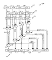
図2を参照すると、第1のレジスタ、第2のレジスタ、および第3のレジスタを特定する命令の実行の、第2の例示的な例を示しており、全体的に200として示している。 Referring to FIG. 2, a second illustrative example of execution of an instruction specifying a first register, a second register, and a third register is shown, generally designated as 200.
特定の実施形態では、第1のレジスタ102は、4つの部分を含む64ビットレジスタとすることができる。たとえば第1のレジスタ102は、第1の部分(Rxx.H3)212、第2の部分(Rxx.H2)214、第3の部分(Rxx.H1)216、および第4の部分(Rxx.H0)218を含むことができる。各部分212〜218は、第1のパスメトリック値に対応する16ビット値を記憶することができる。たとえば第1の部分212は第1の16ビット値(x1)を記憶することができ、第2の部分214は第2の16ビット値(x2)を記憶することができ、第3の部分216は第3の16ビット値(x3)を記憶することができ、第4の部分218は第4の16ビット値(x4)を記憶することができる。第1のパスメトリック値は、図1の第1の値112に対応することができる。たとえば第1のパスメトリック値は、偶数状態(2S)から到着状態(S)に達するために用いられるパスメトリック値の第1の組に対応することができる。
In certain embodiments, the
特定の実施形態では、第2のレジスタ104は、4つの部分を含む64ビットレジスタとすることができる。たとえば第2のレジスタ104は、第1の部分(Rtt.H3)222、第2の部分(Rtt.H2)224、第3の部分(Rtt.H1)226、および第4の部分(Rtt.H0)228を含むことができる。各部分222〜228は、ブランチメトリック値に対応する16ビット値を記憶することができる。たとえば第1の部分222は第1の16ビット値(y1)を記憶することができ、第2の部分224は第2の16ビット値(y2)を記憶することができ、第3の部分226は第3の16ビット値(y3)を記憶することができ、第4の部分228は第4の16ビット値(y4)を記憶することができる。
In certain embodiments, the
特定の実施形態では、第3のレジスタ106は、4つの部分を含む64ビットレジスタとすることができる。たとえば第3のレジスタ106は、第1の部分(Rss.H3)232、第2の部分(Rss.H2)234、第3の部分(Rss.H1)236、および第4の部分(Rss.H0)238を含むことができる。各部分232〜238は、第2のパスメトリック値に対応する16ビット値を記憶することができる。たとえば第1の部分232は第1の16ビット値(z1)を記憶することができ、第2の部分234は第2の16ビット値(z2)を記憶することができ、第3の部分236は第3の16ビット値(z3)を記憶することができ、第4の部分238は第4の16ビット値(z4)を記憶することができる。第2のパスメトリック値は、図1の第3の値116に対応することができる。たとえば第2のパスメトリック値は、偶数状態(2S)から到着状態(S)に達するために用いられるパスメトリック値の第2の組に対応することができる。
In certain embodiments, the
第1のベクトル加算器202は、第1のレジスタ102の第1の部分212からの第1の16ビット値(x1)を、第2のレジスタ104の第1の部分222からの第1の16ビット値(y1)に加算して、第1の16ビット結果を生成するように構成される。第1のベクトル減算器204は、第3のレジスタ106の第1の部分232からの第1の16ビット値(z1)から、第1の16ビット値(y1)を減算して、第2の16ビット結果を生成するように構成される。第1の比較器206は、第1の16ビット結果を第2の16ビット結果と比較するように構成される。比較に基づいて第1の比較器206は、第1の16ビット結果が第2の16ビット結果より大きいかどうか、または第2の16ビット結果が第1の16ビット結果より大きいかどうかを特定する、第1のフラグビット(たとえば1ビット信号)を生成することができる。第1のフラグビットは、プリディケートレジスタ(Pu)210の第1の部分に供給することができ、先行状態が偶数状態(2S)である、または奇数状態(2S+1)である可能性が最も高いかどうかを予測するために用いられる。
The
第1のフラグビットはまた、選択デバイス208に供給され得る。特定の実施形態では、選択デバイス208はマルチプレクサとすることができる。選択デバイス208は、第1のフラグビットに基づいて第1の16ビット結果または第2の16ビット結果のいずれかを選択し、選択結果を第1のレジスタ102の第1の部分212に供給するように構成される。たとえば選択デバイス208は、第1の16ビット結果が第2の16ビット結果より大きいことを第1のフラグビットが示すときは、第1の16ビット結果を第1のレジスタ102の第1の部分212に供給することができる。あるいは選択デバイス208は、第2の16ビット結果が第1の16ビット結果より大きいことを第1のフラグビットが示すときは、第2の16ビット結果を第1のレジスタ102の第1の部分212に供給することができる。
The first flag bit may also be provided to the
さらなるベクトル加算器、ベクトル減算器、および比較器は並列に、かつ第1のベクトル加算器202、第1のベクトル減算器204、および第1の比較器206と実質的に同様に動作することができる。たとえばさらなるベクトル加算器、ベクトル減算器、および比較器は、第1のレジスタ102、第2のレジスタ104、および第3のレジスタ106の対応する部分における16ビット値に基づいて、第2のフラグビット、第3のフラグビット、および第4のフラグビットを生成することができる。第1のレジスタ102の第2、第3、および第4の部分214〜218は、それぞれ第2、第3、および第4のフラグビットに基づいて、16ビット結果を用いて更新することができる。したがって単一実行サイクルの間に、4つの状態を処理することができる。
The further vector adder, vector subtractor, and comparator may operate in parallel and substantially similar to the
図3を参照すると、命令100(たとえば「VACSH」命令)を記憶し処理するように動作可能なシステムの特定の例示的実施形態を開示しており、全体的に300として示している。システム300は、バスインターフェース308を通じて命令キャッシュ310に結合された、メモリ302を含むことができる。特定の実施形態では、システム300のすべてまたは一部分は、プロセッサ内に一体化され得る。
With reference to FIG. 3, a particular exemplary embodiment of a system operable to store and process instructions 100 (eg, “VACSH” instructions) is disclosed and generally designated 300.
命令100(たとえば加算比較選択命令)、および第2の命令352(たとえば第2の加算比較選択命令)は、超長命令語(VLIW)パケット350内に含まれ得る。命令100は、図1〜図2に示されるような第1のレジスタ102、第2のレジスタ104、および第3のレジスタ106を特定することができる。第1のレジスタ102、第2のレジスタ104、および第3のレジスタ106は、汎用レジスタファイル326内に含まれ得る。第1のレジスタ102は、偶数状態(2S)から到着状態(S)に達するために用いられるパスメトリック値の第1の組を記憶することができ、第2のレジスタ104は、ブランチメトリック値を記憶することができ、第3のレジスタ106は、奇数状態(2S+1)から到着状態(S)に達するために用いられるパスメトリック値の第2の組を記憶することができる。命令100はまた、プリディケートレジスタ210を特定することができる。図1〜図2に関連して述べられたように、ベクトル比較演算の結果は、先行状態(たとえば生き残りパス)が、偶数状態(2S)に対応するか、奇数状態(2S+1)に対応するかを予測するために、プリディケートレジスタ210に記憶することができる。プリディケートレジスタ210はまた、汎用レジスタファイル326内に含まれ得る。
An instruction 100 (eg, an add comparison select instruction) and a second instruction 352 (eg, a second add comparison select instruction) may be included in a very long instruction word (VLIW)
メモリ302は、命令100を、バスインターフェース308を通じて命令キャッシュ310に送信することができる。データキャッシュ312はまた、バスインターフェース308を通じてメモリ302に結合され得る。特定の実施形態ではメモリ302は、図1〜図2に関連して述べられたように、命令100を用いてベクトル加算演算、ベクトル減算演算、ベクトル比較演算、ベクトル選択演算、またはそれらの任意の組合せを行うデコーダによってアクセス可能とすることができる。たとえばデコーダは、図5を参照してさらに述べられるように、コーダ/デコーダ(CODEC)の一部とすることができる。
The
命令キャッシュ310は、バス311を通じてシーケンサ314に結合され得る。シーケンサ314は、割り込みレジスタ(図示せず)から取り出すことができる汎用割り込み316を受け取ることができる。特定の実施形態では、命令キャッシュ310は、複数の現行命令レジスタ(図示せず)を通じて、シーケンサ314に結合することができ、これらはバス311に結合され、システム300の特定のスレッド(たとえばハードウェアスレッド)に関連付けられ得る。特定の実施形態では、プロセッサ300は、6つのスレッドを含むインターリーブされたマルチスレッドプロセッサとすることができる。他の特定の実施形態では、プロセッサ300は、3つまたは4つのスレッドを含むことができる。
特定の実施形態ではバス311は、128ビットバスとすることができ、シーケンサ314は、命令パケット(たとえば命令100および第2の命令352を含む、超長命令語(VLIW)命令パケット350)を通じて、メモリ302から命令を取り出すように構成することができる。シーケンサ314は、第1の命令実行ユニット318、第2の命令実行ユニット320、第3の命令実行ユニット322、および第4の命令実行ユニット324に結合され得る。より少ないまたはより多い命令実行ユニットが存在し得ることに留意されるべきである。各命令実行ユニット318〜324は、第1のバス328を通じて汎用レジスタファイル326に結合され得る。汎用レジスタファイル326はまた、第2のバス330を通じて、シーケンサ314、データキャッシュ312、およびメモリ302に結合され得る。
In certain embodiments, the
システム300はまた、割り込み(たとえば汎用割り込み316)を受け入れるかどうかを判断するため、および命令の実行を制御するために、シーケンサ314内の制御ロジックによってアクセスされ得る、ビットを記憶するためのスーパバイザ制御レジスタ332、およびグローバル制御レジスタ334を含むことができる。
特定の実施形態では、実行ユニット318〜324のいずれも、図1の命令100を実行して第1の結果122および第2の結果124を生成することができる。別の実施形態では、実行ユニット318〜324のすべてではないがいくつかは、命令100を実行することができる。たとえば実行ユニット318〜324は、図2に関連して述べられたようなベクトル加算器、ベクトル減算器、比較器、および選択デバイスを含む演算論理ユニット(ALU)を含むことができる。実行ユニット318〜324は、図2に関連して述べられたベクトル加算器202などのベクトル加算器を用いて、第1のレジスタ102に記憶されたパスメトリック値の第1の組を、第2のレジスタ104に記憶されたブランチメトリック値に加算することによって、第1の結果を生成することができる。実行ユニット318〜324は、図2に関連して述べられたベクトル減算器204などのベクトル減算器を用いて、第3のレジスタ106に記憶されたパスメトリック値の第2の組から、第2のレジスタ104に記憶されたブランチメトリック値を減算することによって、第2の結果を生成することができる。実行ユニット318〜324は、第1の結果を第2の結果と比較して、どちらの結果が大きいかを判定し、比較の結果を知らせる信号をプリディケートレジスタ210に供給することができる。プリディケートレジスタ210に記憶された情報は、先行状態が偶数状態(2S)に対応するか、奇数状態(2S+1)に対応するかを予測するために用いることができる。
In certain embodiments, any of the execution units 318-324 can execute the
したがって、符号化されたデータストリームの復号時に、符号化されたデータ信号の先行状態は、単一命令を用いて、到着状態を回復するために用いられたパスメトリックから予測することができる。さらに比較に応じて、第1の結果または第2の結果のいずれかを、後続の状態プレディケーションにおいて用いられるように第1のレジスタに記憶することができる。命令100は、コードサイズの全体的な低減を達成し、先行状態を予測するために単一命令を使用することにより、プロセッサが行う実行サイクルをより少なくすることができる。命令100および第2の命令352を同時に実行することは、システム300が複数のビタビパスに対応する複数の先行状態を同時に予測することを可能にすることによって、効率を向上し得ることが理解されるであろう。
Thus, upon decoding of the encoded data stream, the preceding state of the encoded data signal can be predicted from the path metric used to recover the arrival state using a single instruction. Further, depending on the comparison, either the first result or the second result can be stored in the first register for use in subsequent state predication. The
図3に示されるシステム300は、例示のみであることが留意されるべきである。開示した命令および技法は、他のアーキテクチャ(たとえばマイクロアーキテクチャ、およびデジタル信号プロセッサ(DSP)アーキテクチャ)によってサポートされ、その中で実行され得る。たとえば代替のDSPアーキテクチャは、図3のシステム300より多い、少ない、および/または異なる構成要素を含むことができる。例示として、代替のDSPアーキテクチャは、図3に示されるような4つの実行ユニットの代わりに、2つの実行ユニット、および2つのロード/記憶ユニットを含むことができる。
It should be noted that the
図4を参照すると、第1のレジスタ、第2のレジスタ、および第3のレジスタを特定する命令を処理する方法の特定の例示的実施形態のフローチャートを示しており、全体的に400として示している。例示的実施形態では方法400は、図3のシステム300において行うことができ、図1〜図2を参照して示され得る。
Referring to FIG. 4, there is shown a flowchart of a particular exemplary embodiment of a method for processing an instruction specifying a first register, a second register, and a third register, indicated generally as 400. Yes. In the exemplary embodiment,
方法400は、410で、第1のレジスタ、第2のレジスタ、および第3のレジスタを特定する命令を受け取るステップを含むことができる。たとえば図3において、命令100は、実行ユニット318〜324の1つによって受け取られ得る。命令100は、第1のレジスタ102、第2のレジスタ104、および第3のレジスタ106を特定することができる。
The
方法400はまた、420で、命令を実行するステップを含むことができる。たとえば図3において命令100は、実行ユニット318〜324の1つによって実行され得る。命令を実行するステップ420は、422で、第1のレジスタからの第1の値を、第2のレジスタからの第2の値に加算して、第1の結果を生成するステップを含むことができる。たとえば図3において、実行ユニット318〜324の1つのALU内のベクトル加算器は、第1のレジスタ102に記憶されたパスメトリック値の第1の組を、第2のレジスタ104に記憶されたブランチメトリック値に加算することによって、第1の結果を生成することができる。命令を実行するステップ420はまた、424で、第3のレジスタからの第3の値から、第2の値を減算して、第2の結果を生成するステップを含むことができる。たとえば図3において、実行ユニット318〜324の1つのALU内のベクトル減算器は、第3のレジスタ106に記憶されたパスメトリック値の第2の組から、第2のレジスタ104に記憶されたブランチメトリック値を減算することによって、第2の結果を生成することができる。命令を実行するステップ420はまた、426で、第1の結果を第2の結果と比較して、比較結果を生成するステップを含むことができる。たとえば図3において、実行ユニット318〜324の1つのALU内の比較器は、第1の結果を第2の結果と比較して、結果のどちらが大きいかを判定し、大きい方の結果を知らせる信号を、プリディケートレジスタ210に供給することができる。プリディケートレジスタ210に記憶された情報は、先行状態が偶数状態(2S)に対応するか、奇数状態(2S+1)に対応するかを予測するために用いることができる。
The
図4の方法400は、フィールドプログラマブルゲートアレイ(FPGA)デバイス、特定用途向け集積回路(ASIC)、中央処理装置(CPU)などの処理装置、デジタル信号プロセッサ(DSP)、コントローラ、他のハードウェアデバイス、ファームウェア、またはそれらの任意の組合せによって実施してもよい。例として、図4の方法400は、図3および図5に関連して述べたように、プログラムコードまたは命令を実行するプロセッサ、またはその構成要素によって行われ得る。
The
図5を参照すると、第1のレジスタ102、第2のレジスタ104、および第3のレジスタ106を特定する命令100(たとえば加算比較選択命令)を記憶するメモリ532を含む、ワイヤレスデバイスの特定の例示的実施形態のブロック図を示しており、全体的に500として示している。デバイス500は、メモリ532に結合された、デジタル信号プロセッサ(DSP)などのプロセッサ564を含む。命令キャッシュ(たとえば例示の命令キャッシュ310)はまた、メモリ532およびプロセッサ564に結合され得る。特定の実施形態ではメモリ532は、命令100などのプロセッサ564によって実行可能な命令を記憶し、命令キャッシュ310に送信する。
Referring to FIG. 5, a particular illustration of a wireless device including a
図5はまた、プロセッサ564およびディスプレイ528に結合された、ディスプレイコントローラ526を示す。コーダ/デコーダ(CODEC)534はまた、プロセッサ564に結合され得る。スピーカ536およびマイク538は、CODEC534に結合され得る。図5はまたワイヤレスコントローラ540は、プロセッサ564およびワイヤレスアンテナ542に結合され得ることを示す。特定の実施形態では、プロセッサ564、ディスプレイコントローラ526、メモリ532、CODEC534、およびワイヤレスコントローラ540は、システムインパッケージまたはシステムオンチップデバイス522に含まれる。特定の実施形態では、命令100を含んだメモリ532または命令キャッシュ310は、電子デバイス(たとえばワイヤレスデバイス500)におけるオーディオまたはビデオ復号時に、命令100を用いて畳み込み復号を行う、CODEC534によってアクセス可能とすることができる。特定の実施形態では、CODEC534はビタビデコーダを含む。
FIG. 5 also shows a
処理されると、命令100は、プロセッサ564に、第1のレジスタ102に記憶されたパスメトリック値の第1の組を、第2のレジスタ104に記憶されたブランチメトリック値に加算することによって、第1の結果を生成させる。命令100はまた、プロセッサ564に、第3のレジスタ106に記憶されたパスメトリック値の第2の組から、第2のレジスタ104に記憶されたブランチメトリック値を減算することによって、第2の結果を生成させる。第1および第2の結果を生成すると、命令100はプロセッサ564に、どちらの結果が大きいかを判定するために、第1の結果を第2の結果と比較させ、大きい方の結果を知らせる信号を、プリディケートレジスタ210に供給させることができる。比較に基づいて第1のレジスタ102は、第1の結果または第2の結果のいずれかを用いて更新することができる。たとえば第1の結果が第2の結果より大きかった場合は、第1の結果を第1のレジスタ102に記憶することができる。あるいは第2の結果が第1の結果より大きかった場合は、第2の結果を第1のレジスタ102に記憶することができる。
Once processed,
特定の実施形態では、入力デバイス530および電源544は、システムオンチップデバイス522に結合される。さらに特定の実施形態では、図5に示されるように、ディスプレイ528、入力デバイス530、スピーカ536、マイク538、ワイヤレスアンテナ542、および電源544は、システムオンチップデバイス522の外部となる。しかしディスプレイ528、入力デバイス530、スピーカ536、マイク538、ワイヤレスアンテナ542、および電源544のそれぞれは、インターフェースまたはコントローラなどの、システムオンチップデバイス522の構成要素に結合され得る。
In certain embodiments,
図5は、ワイヤレス通信デバイスを示すが、プロセッサ564などの加算比較選択命令を実行するためのプロセッサ、メモリ532、および加算比較選択命令を記憶する命令キャッシュ310は、代替としてセットトップボックス、音楽プレーヤ、ビデオプレーヤ、娯楽ユニット、ナビゲーションデバイス、携帯情報端末(PDA)、固定ロケーションデータユニット、またはコンピュータ内に一体化され得ることが留意されるべきである。
FIG. 5 shows a wireless communication device, but a processor such as a
述べられた実施形態に関連して、第1のレジスタ、第2のレジスタ、および第3のレジスタを特定する命令を記憶するための手段を含む、装置を開示している。たとえば記憶するための手段は、図3のメモリ302、図5のメモリ532、図3および図5の命令キャッシュ310、命令を記憶するように構成された1つまたは複数の他のデバイス、またはそれらの任意の組合せとすることができる。
In connection with the described embodiments, an apparatus is disclosed that includes means for storing instructions identifying a first register, a second register, and a third register. For example, the means for storing includes the
装置はまた、命令を実行するための手段を含むことができる。たとえば命令を実行するための手段は、図2のベクトル加算器、図2のベクトル減算器、図2の比較器、図2の選択デバイス、図3の実行ユニット318、320、322、および324の1つまたは複数、図5のプロセッサ564、命令を実行するように構成された1つまたは複数の他のデバイス、またはそれらの任意の組合せを含むことができる。
The apparatus can also include means for executing the instructions. For example, the means for executing the instructions include the vector adder of FIG. 2, the vector subtractor of FIG. 2, the comparator of FIG. 2, the selection device of FIG. 2, the
装置はまた、第1のレジスタからの第1の値を、第2のレジスタからの第2の値に加算して、第1の結果を生成するための手段を含むことができる。たとえば加算するための手段は、図2のベクトル加算器、図3の実行ユニット318、320、322、および324の1つまたは複数、図5のプロセッサ564、値を加算するように構成された1つまたは複数の他のデバイス、またはそれらの任意の組合せを含むことができる。
The apparatus can also include means for adding the first value from the first register to the second value from the second register to produce a first result. For example, the means for adding is the vector adder of FIG. 2, one or more of the
装置はまた、第3のレジスタからの第3の値から、第2の値を減算して、第2の結果を生成するための手段を含むことができる。たとえば減算するための手段は、図2のベクトル減算器、図3の実行ユニット318、320、322、および324の1つまたは複数、図5のプロセッサ564、値を減算するように構成された1つまたは複数の他のデバイス、またはそれらの任意の組合せを含むことができる。
The apparatus can also include means for subtracting the second value from the third value from the third register to produce a second result. For example, the means for subtracting is the vector subtractor of FIG. 2, one or more of the
装置はまた、第1の結果を第2の結果と比較するための手段を含むことができる。たとえば比較するための手段は、図2の比較器、図3の実行ユニット318、320、322、および324の1つまたは複数、図5のプロセッサ564、結果を比較するように構成された1つまたは複数の他のデバイス、またはそれらの任意の組合せを含むことができる。
The apparatus can also include means for comparing the first result with the second result. For example, the means for comparing is a comparator in FIG. 2, one or more of the
当業者ならさらに、様々な例示の論理ブロック、構成、モジュール、回路、および本明細書で開示した実施形態に関連して述べられたアルゴリズムステップは、電子ハードウェア、コンピュータソフトウェア、またはそれらの両方の組合せとして実施できることが理解されよう。様々な例示の構成要素、ブロック、構成、モジュール、回路、およびステップについて、一般にそれらの機能の観点から述べてきた。このような機能がハードウェアとして実施されるか、ソフトウェアとして実施されるかは、特定の用途、および全体のシステムに課される設計上の制約による。当業者は、述べられた機能を、それぞれの特定の用途に対して様々な方法において実施することができるが、このような実施の決定は、本開示の範囲からの逸脱を生じるものと解釈されるべきではない。 Those skilled in the art further understand that various exemplary logic blocks, configurations, modules, circuits, and algorithm steps described in connection with the embodiments disclosed herein may be implemented in electronic hardware, computer software, or both. It will be understood that it can be implemented as a combination. Various illustrative components, blocks, configurations, modules, circuits, and steps have been described generally in terms of their functionality. Whether such functionality is implemented as hardware or software depends upon the particular application and design constraints imposed on the overall system. Those skilled in the art can implement the described functions in a variety of ways for each particular application, but such implementation decisions are to be construed as departing from the scope of the present disclosure. Should not.
本明細書で開示した実施形態に関連して述べられた方法またはアルゴリズムのステップは、直接ハードウェアにおいて、プロセッサによって実行されるソフトウェアモジュールにおいて、または両者の組合せにおいて具体化され得る。ソフトウェアモジュールは、ランダムアクセスメモリ(RAM)、フラッシュメモリ、リードオンリメモリ(ROM)、プログラマブルリードオンリメモリ(PROM)、消去可能プログラマブルリードオンリメモリ(EPROM)、電気的消去可能プログラマブルリードオンリメモリ(EEPROM)、レジスタ、ハードディスク、リムーバブルディスク、コンパクトディスクリードオンリメモリ(CD-ROM)、または当技術分野で知られている任意の他の形の記憶媒体内に存在することができる。例示の非一時的(たとえば有形の)記憶媒体は、プロセッサが記憶媒体から情報を読み出し、それに情報を書き込むことができるように、プロセッサに結合される。代替として記憶媒体は、プロセッサと一体とすることができる。プロセッサおよび記憶媒体は、特定用途向け集積回路(ASIC)内に存在することができる。ASICは、コンピューティングデバイスまたはユーザ端末内に存在することができる。代替としてプロセッサおよび記憶媒体は、コンピューティングデバイスまたはユーザ端末内に個別構成要素として存在することができる。 The method or algorithm steps described in connection with the embodiments disclosed herein may be embodied directly in hardware, in software modules executed by a processor, or in a combination of both. Software modules include random access memory (RAM), flash memory, read only memory (ROM), programmable read only memory (PROM), erasable programmable read only memory (EPROM), electrically erasable programmable read only memory (EEPROM) , A register, a hard disk, a removable disk, a compact disk read only memory (CD-ROM), or any other form of storage medium known in the art. An exemplary non-transitory (eg, tangible) storage medium is coupled to the processor such that the processor can read information from, and write information to, the storage medium. In the alternative, the storage medium may be integral to the processor. The processor and the storage medium can reside in an application specific integrated circuit (ASIC). The ASIC can reside in a computing device or user terminal. In the alternative, the processor and the storage medium may reside as discrete components in a computing device or user terminal.
開示した実施形態の上記の説明は、当業者が開示した実施形態を作製または使用することを可能にするように示された。これらの実施形態に対する様々な変更は当業者には容易に明らかとなり、本明細書で定義される原理は、本開示の範囲から逸脱せずに他の実施形態に応用され得る。したがって本開示は、本明細書に示される実施形態に限定されるものではなく、添付の「特許請求の範囲」によって定義される原理および新規な特徴と一貫したできる限り広い範囲が与えられるべきである。 The above description of the disclosed embodiments has been presented to enable any person skilled in the art to make or use the disclosed embodiments. Various modifications to these embodiments will be readily apparent to those skilled in the art, and the principles defined herein may be applied to other embodiments without departing from the scope of the disclosure. Accordingly, the present disclosure is not intended to be limited to the embodiments shown herein, but is to be accorded the widest possible scope consistent with the principles and novel features defined by the appended claims. is there.
100 命令
102 第1のレジスタ
104 第2のレジスタ
106 第3のレジスタ
110 プリディケートレジスタ
112 第1の値
114 第2の値
116 第3の値
122 第1の結果
124 第2の結果
126 選択結果
210 プリディケートレジスタ
302 メモリ
308 バスインターフェース
310 命令キャッシュ
311 バス
312 データキャッシュ
314 シーケンサ
316 汎用割り込み
318 命令実行ユニット
320 命令実行ユニット
322 命令実行ユニット
324 命令実行ユニット
326 汎用レジスタファイル
330 バス
332 スーパバイザ制御レジスタ
334 グローバル制御レジスタ
350 超長命令語(VLIW)パケット
352 第2の命令
528 ディスプレイ
530 入力デバイス
526 ディスプレイコントローラ
532 メモリ
536 スピーカ
538 マイク
540 ワイヤレスコントローラ
544 電源
100 instructions
102 First register
104 Second register
106 Third register
110 Predicate register
112 First value
114 Second value
116 Third value
122 First result
124 Second result
126 selection results
210 Predicate register
302 memory
308 Bus interface
310 instruction cache
311 bus
312 Data cache
314 PLC
316 General interrupt
318 Instruction execution unit
320 instruction execution unit
322 instruction execution unit
324 instruction execution unit
326 General-purpose register file
330 bus
332 Supervisor Control Register
334 Global Control Register
350 Very Long Instruction Word (VLIW) packet
352 Second instruction
528 display
530 input device
526 display controller
532 memory
536 speaker
538 microphone
540 wireless controller
544 power supply
Claims (25)
前記プロセッサによって、前記第1のレジスタからの第1の値を、前記第2のレジスタからの第2の値に加算するようにベクトル加算演算が行われ、
前記第3のレジスタからの第3の値から、前記第2の値を減算するようにベクトル減算演算が行われ、
前記ベクトル加算演算の結果を、前記ベクトル減算演算の結果と比較するようにベクトル比較演算が行われる、
装置。 An apparatus comprising a memory for storing an instruction specifying a first register, a second register, and a third register, wherein when the instruction is executed by a processor,
The processor performs a vector addition operation to add the first value from the first register to the second value from the second register,
A vector subtraction operation is performed to subtract the second value from the third value from the third register;
A vector comparison operation is performed to compare the result of the vector addition operation with the result of the vector subtraction operation;
apparatus.
前記ベクトル比較演算に基づいて、前記ベクトル加算演算の前記結果、または前記ベクトル減算演算の前記結果を選択し、
前記選択結果を用いて前記第1のレジスタを更新する、
請求項1に記載の装置。 When the instruction is executed by the processor, a vector selection operation is performed,
Based on the vector comparison operation, select the result of the vector addition operation or the result of the vector subtraction operation;
Updating the first register with the selection result;
The apparatus according to claim 1.
第1のレジスタ、第2のレジスタ、および第3のレジスタを特定する前記命令を受け取るステップと、
プロセッサによって前記命令を実行するステップであって、
前記第1のレジスタからの第1の値を、前記第2のレジスタからの第2の値に加算して、第1の結果を生成するステップと、
前記第3のレジスタからの第3の値から、第2の値を減算して、第2の結果を生成するステップと、
前記第1の結果を前記第2の結果と比較するステップと
を含む、前記命令を実行するステップと
を含む命令を実行する方法。 A method of executing an instruction, the method receiving the instruction identifying a first register, a second register, and a third register;
Executing the instructions by a processor, comprising:
Adding a first value from the first register to a second value from the second register to generate a first result;
Subtracting a second value from a third value from the third register to generate a second result;
Comparing the first result with the second result, and executing the instruction.
前記第1の結果を前記第2の結果と比較するステップに基づいて、前記第1の結果または前記第2の結果を選択するステップと、
前記選択結果を用いて前記第1のレジスタを更新するステップと
をさらに含む、請求項11に記載の命令を実行する方法。 Executing the instructions comprises:
Selecting the first result or the second result based on comparing the first result to the second result; and
12. The method of executing an instruction according to claim 11, further comprising: updating the first register using the selection result.
前記命令を実行するための手段であって、
前記第1のレジスタからの第1の値を、前記第2のレジスタからの第2の値に加算して、第1の結果を生成するための手段と、
前記第3のレジスタからの第3の値から、第2の値を減算して、第2の結果を生成するための手段と、
前記第1の結果を、前記第2の結果と比較するための手段と
を備える、前記命令を実行するための手段と
を備える装置。 Means for storing instructions identifying the first register, the second register, and the third register;
Means for executing the instructions, comprising:
Means for adding the first value from the first register to the second value from the second register to produce a first result;
Means for subtracting a second value from a third value from the third register to produce a second result;
Means for comparing the first result with means for comparing the second result with means for executing the instruction.
第1のレジスタ、第2のレジスタ、および第3のレジスタを特定する単一命令を受け取らせ、
前記単一命令を実行させる、
プログラムコードを含む、コンピュータ可読記憶媒体であって、
前記単一命令を実行することは、
前記第1のレジスタからの第1の値を、前記第2のレジスタからの第2の値に加算して、第1の結果を生成し、
前記第3のレジスタからの第3の値から、第2の値を減算して、第2の結果を生成し、
前記第1の結果を前記第2の結果と比較すること
を含む、コンピュータ可読記憶媒体。 When executed by a processor, the processor
Receive a single instruction identifying the first register, the second register, and the third register;
Causing the single instruction to be executed;
A computer readable storage medium containing program code,
Executing the single instruction is
Adding a first value from the first register to a second value from the second register to produce a first result;
Subtracting a second value from a third value from the third register to produce a second result;
Comparing the first result with the second result. A computer readable storage medium.
前記第1の結果を前記第2の結果と比較することに基づいて、前記第1の結果または前記第2の結果の1つを選択すること、および
前記選択結果を用いて前記第1のレジスタを更新すること
をさらに含む、請求項22に記載のコンピュータ可読記憶媒体。 Executing the single instruction;
Selecting one of the first result or the second result based on comparing the first result with the second result, and using the selection result, the first register 23. The computer readable storage medium of claim 22, further comprising: updating.
Applications Claiming Priority (3)
| Application Number | Priority Date | Filing Date | Title |
|---|---|---|---|
| US13/841,878 | 2013-03-15 | ||
| US13/841,878 US9389854B2 (en) | 2013-03-15 | 2013-03-15 | Add-compare-select instruction |
| PCT/US2014/024203 WO2014150778A1 (en) | 2013-03-15 | 2014-03-12 | Add-compare-select instruction |
Publications (3)
| Publication Number | Publication Date |
|---|---|
| JP2016517577A JP2016517577A (en) | 2016-06-16 |
| JP2016517577A5 JP2016517577A5 (en) | 2017-01-05 |
| JP6203935B2 true JP6203935B2 (en) | 2017-09-27 |
Family
ID=50483523
Family Applications (1)
| Application Number | Title | Priority Date | Filing Date |
|---|---|---|---|
| JP2016501437A Expired - Fee Related JP6203935B2 (en) | 2013-03-15 | 2014-03-12 | Addition comparison selection instruction |
Country Status (6)
| Country | Link |
|---|---|
| US (1) | US9389854B2 (en) |
| EP (1) | EP2972786B1 (en) |
| JP (1) | JP6203935B2 (en) |
| KR (1) | KR101746681B1 (en) |
| CN (1) | CN105027076B (en) |
| WO (1) | WO2014150778A1 (en) |
Families Citing this family (3)
| Publication number | Priority date | Publication date | Assignee | Title |
|---|---|---|---|---|
| CN107315715B (en) * | 2016-04-26 | 2020-11-03 | 中科寒武纪科技股份有限公司 | Apparatus and method for performing matrix addition/subtraction operation |
| CN107315717B (en) * | 2016-04-26 | 2020-11-03 | 中科寒武纪科技股份有限公司 | Device and method for executing vector four-rule operation |
| CN110275693B (en) * | 2018-03-15 | 2023-08-22 | 华为技术有限公司 | Multi-addend adder circuit for random calculation |
Family Cites Families (18)
| Publication number | Priority date | Publication date | Assignee | Title |
|---|---|---|---|---|
| US5151904A (en) * | 1990-09-27 | 1992-09-29 | The Titan Corporation | Reconfigurable, multi-user viterbi decoder |
| JPH05206873A (en) * | 1992-01-29 | 1993-08-13 | Sony Corp | Reproducing device |
| JP3198607B2 (en) * | 1992-03-31 | 2001-08-13 | ソニー株式会社 | Magnetic recording / reproducing method |
| JP3241210B2 (en) | 1994-06-23 | 2001-12-25 | 沖電気工業株式会社 | Viterbi decoding method and Viterbi decoding circuit |
| US6163581A (en) * | 1997-05-05 | 2000-12-19 | The Regents Of The University Of California | Low-power state-sequential viterbi decoder for CDMA digital cellular applications |
| US5987490A (en) * | 1997-11-14 | 1999-11-16 | Lucent Technologies Inc. | Mac processor with efficient Viterbi ACS operation and automatic traceback store |
| US20020031195A1 (en) * | 2000-09-08 | 2002-03-14 | Hooman Honary | Method and apparatus for constellation decoder |
| US6848074B2 (en) | 2001-06-21 | 2005-01-25 | Arc International | Method and apparatus for implementing a single cycle operation in a data processing system |
| US7661059B2 (en) * | 2001-08-06 | 2010-02-09 | Analog Devices, Inc. | High performance turbo and Viterbi channel decoding in digital signal processors |
| US7043682B1 (en) | 2002-02-05 | 2006-05-09 | Arc International | Method and apparatus for implementing decode operations in a data processor |
| US8140947B2 (en) | 2005-09-30 | 2012-03-20 | Agere Systems Inc. | Method and apparatus for storing survivor paths in a Viterbi detector using systematic pointer exchange |
| US7725516B2 (en) | 2005-10-05 | 2010-05-25 | Qualcomm Incorporated | Fast DCT algorithm for DSP with VLIW architecture |
| US8356160B2 (en) * | 2008-01-15 | 2013-01-15 | International Business Machines Corporation | Pipelined multiple operand minimum and maximum function |
| US8255780B2 (en) * | 2009-02-18 | 2012-08-28 | Saankhya Labs Pvt Ltd. | Scalable VLIW processor for high-speed viterbi and trellis coded modulation decoding |
| CN102122275A (en) * | 2010-01-08 | 2011-07-13 | 上海芯豪微电子有限公司 | Configurable processor |
| JP4856288B1 (en) * | 2010-08-10 | 2012-01-18 | パイオニア株式会社 | Impedance matching device and control method |
| US8694878B2 (en) | 2011-06-15 | 2014-04-08 | Texas Instruments Incorporated | Processor instructions to accelerate Viterbi decoding |
| US10120692B2 (en) | 2011-07-28 | 2018-11-06 | Qualcomm Incorporated | Methods and apparatus for storage and translation of an entropy encoded instruction sequence to executable form |
-
2013
- 2013-03-15 US US13/841,878 patent/US9389854B2/en active Active
-
2014
- 2014-03-12 KR KR1020157029138A patent/KR101746681B1/en active IP Right Grant
- 2014-03-12 JP JP2016501437A patent/JP6203935B2/en not_active Expired - Fee Related
- 2014-03-12 WO PCT/US2014/024203 patent/WO2014150778A1/en active Application Filing
- 2014-03-12 EP EP14717293.6A patent/EP2972786B1/en active Active
- 2014-03-12 CN CN201480012927.5A patent/CN105027076B/en active Active
Also Published As
| Publication number | Publication date |
|---|---|
| WO2014150778A1 (en) | 2014-09-25 |
| KR20150132387A (en) | 2015-11-25 |
| US9389854B2 (en) | 2016-07-12 |
| EP2972786A1 (en) | 2016-01-20 |
| JP2016517577A (en) | 2016-06-16 |
| KR101746681B1 (en) | 2017-06-13 |
| CN105027076A (en) | 2015-11-04 |
| EP2972786B1 (en) | 2021-12-01 |
| CN105027076B (en) | 2018-07-20 |
| US20140281420A1 (en) | 2014-09-18 |
Similar Documents
| Publication | Publication Date | Title |
|---|---|---|
| JP6022581B2 (en) | FIFO load instruction | |
| US8868888B2 (en) | System and method of executing instructions in a multi-stage data processing pipeline | |
| JP6203935B2 (en) | Addition comparison selection instruction | |
| JP2009514097A (en) | Improved pipelined digital signal processor | |
| JP5341194B2 (en) | System and method for executing a linear feedback shift instruction | |
| JP6313204B2 (en) | Table call instructions for frequently called functions | |
| US20050157823A1 (en) | Technique for improving viterbi decoder performance | |
| WO2013036950A1 (en) | Instruction packet including multiple instructions having a common destination | |
| KR20140078764A (en) | Determining top n or bottom n data values | |
| CN109313594B (en) | Parity checking for instruction packets | |
| US9678754B2 (en) | System and method of processing hierarchical very long instruction packets | |
| JP4383496B1 (en) | Microcomputer and instruction execution method thereof | |
| JP2019523503A (en) | System and method for piecewise linear approximation | |
| WO2013025641A1 (en) | Bit splitting instruction | |
| WO2013069551A1 (en) | Digital signal processor, program control method, and control program | |
| US20120117360A1 (en) | Dedicated instructions for variable length code insertion by a digital signal processor (dsp) | |
| JP2014045480A (en) | High speed add-compare-select circuit | |
| JP5794172B2 (en) | Processor, system and method of operating processor | |
| JP2002217747A (en) | Viterbi decoding processing unit |
Legal Events
| Date | Code | Title | Description |
|---|---|---|---|
| A521 | Request for written amendment filed |
Free format text: JAPANESE INTERMEDIATE CODE: A523 Effective date: 20161116 |
|
| A621 | Written request for application examination |
Free format text: JAPANESE INTERMEDIATE CODE: A621 Effective date: 20161116 |
|
| A871 | Explanation of circumstances concerning accelerated examination |
Free format text: JAPANESE INTERMEDIATE CODE: A871 Effective date: 20161116 |
|
| A975 | Report on accelerated examination |
Free format text: JAPANESE INTERMEDIATE CODE: A971005 Effective date: 20170118 |
|
| A131 | Notification of reasons for refusal |
Free format text: JAPANESE INTERMEDIATE CODE: A131 Effective date: 20170306 |
|
| A521 | Request for written amendment filed |
Free format text: JAPANESE INTERMEDIATE CODE: A523 Effective date: 20170602 |
|
| TRDD | Decision of grant or rejection written | ||
| A01 | Written decision to grant a patent or to grant a registration (utility model) |
Free format text: JAPANESE INTERMEDIATE CODE: A01 Effective date: 20170807 |
|
| A61 | First payment of annual fees (during grant procedure) |
Free format text: JAPANESE INTERMEDIATE CODE: A61 Effective date: 20170830 |
|
| R150 | Certificate of patent or registration of utility model |
Ref document number: 6203935 Country of ref document: JP Free format text: JAPANESE INTERMEDIATE CODE: R150 |
|
| LAPS | Cancellation because of no payment of annual fees |