JP6203376B2 - Method for melting metal material in melting plant and melting plant - Google Patents
Method for melting metal material in melting plant and melting plant Download PDFInfo
- Publication number
- JP6203376B2 JP6203376B2 JP2016509586A JP2016509586A JP6203376B2 JP 6203376 B2 JP6203376 B2 JP 6203376B2 JP 2016509586 A JP2016509586 A JP 2016509586A JP 2016509586 A JP2016509586 A JP 2016509586A JP 6203376 B2 JP6203376 B2 JP 6203376B2
- Authority
- JP
- Japan
- Prior art keywords
- shell
- melting
- loading
- metal material
- supply means
- Prior art date
- Legal status (The legal status is an assumption and is not a legal conclusion. Google has not performed a legal analysis and makes no representation as to the accuracy of the status listed.)
- Active
Links
Images


Classifications
-
- C—CHEMISTRY; METALLURGY
- C21—METALLURGY OF IRON
- C21C—PROCESSING OF PIG-IRON, e.g. REFINING, MANUFACTURE OF WROUGHT-IRON OR STEEL; TREATMENT IN MOLTEN STATE OF FERROUS ALLOYS
- C21C5/00—Manufacture of carbon-steel, e.g. plain mild steel, medium carbon steel or cast steel or stainless steel
- C21C5/52—Manufacture of steel in electric furnaces
- C21C5/527—Charging of the electric furnace
-
- C—CHEMISTRY; METALLURGY
- C21—METALLURGY OF IRON
- C21C—PROCESSING OF PIG-IRON, e.g. REFINING, MANUFACTURE OF WROUGHT-IRON OR STEEL; TREATMENT IN MOLTEN STATE OF FERROUS ALLOYS
- C21C5/00—Manufacture of carbon-steel, e.g. plain mild steel, medium carbon steel or cast steel or stainless steel
- C21C5/56—Manufacture of steel by other methods
- C21C5/562—Manufacture of steel by other methods starting from scrap
- C21C5/565—Preheating of scrap
-
- F—MECHANICAL ENGINEERING; LIGHTING; HEATING; WEAPONS; BLASTING
- F27—FURNACES; KILNS; OVENS; RETORTS
- F27B—FURNACES, KILNS, OVENS, OR RETORTS IN GENERAL; OPEN SINTERING OR LIKE APPARATUS
- F27B3/00—Hearth-type furnaces, e.g. of reverberatory type; Tank furnaces
- F27B3/08—Hearth-type furnaces, e.g. of reverberatory type; Tank furnaces heated electrically, with or without any other source of heat
- F27B3/085—Arc furnaces
-
- F—MECHANICAL ENGINEERING; LIGHTING; HEATING; WEAPONS; BLASTING
- F27—FURNACES; KILNS; OVENS; RETORTS
- F27B—FURNACES, KILNS, OVENS, OR RETORTS IN GENERAL; OPEN SINTERING OR LIKE APPARATUS
- F27B3/00—Hearth-type furnaces, e.g. of reverberatory type; Tank furnaces
- F27B3/10—Details, accessories, or equipment peculiar to hearth-type furnaces
- F27B3/18—Arrangements of devices for charging
- F27B3/183—Charging of arc furnaces vertically through the roof, e.g. in three points
- F27B3/186—Charging in a vertical chamber adjacent to the melting chamber
-
- F—MECHANICAL ENGINEERING; LIGHTING; HEATING; WEAPONS; BLASTING
- F27—FURNACES; KILNS; OVENS; RETORTS
- F27B—FURNACES, KILNS, OVENS, OR RETORTS IN GENERAL; OPEN SINTERING OR LIKE APPARATUS
- F27B3/00—Hearth-type furnaces, e.g. of reverberatory type; Tank furnaces
- F27B3/10—Details, accessories, or equipment peculiar to hearth-type furnaces
- F27B3/20—Arrangements of heating devices
- F27B3/205—Burners
-
- F—MECHANICAL ENGINEERING; LIGHTING; HEATING; WEAPONS; BLASTING
- F27—FURNACES; KILNS; OVENS; RETORTS
- F27D—DETAILS OR ACCESSORIES OF FURNACES, KILNS, OVENS, OR RETORTS, IN SO FAR AS THEY ARE OF KINDS OCCURRING IN MORE THAN ONE KIND OF FURNACE
- F27D11/00—Arrangement of elements for electric heating in or on furnaces
- F27D11/08—Heating by electric discharge, e.g. arc discharge
- F27D11/10—Disposition of electrodes
-
- F—MECHANICAL ENGINEERING; LIGHTING; HEATING; WEAPONS; BLASTING
- F27—FURNACES; KILNS; OVENS; RETORTS
- F27D—DETAILS OR ACCESSORIES OF FURNACES, KILNS, OVENS, OR RETORTS, IN SO FAR AS THEY ARE OF KINDS OCCURRING IN MORE THAN ONE KIND OF FURNACE
- F27D13/00—Apparatus for preheating charges; Arrangements for preheating charges
- F27D13/002—Preheating scrap
-
- F—MECHANICAL ENGINEERING; LIGHTING; HEATING; WEAPONS; BLASTING
- F27—FURNACES; KILNS; OVENS; RETORTS
- F27D—DETAILS OR ACCESSORIES OF FURNACES, KILNS, OVENS, OR RETORTS, IN SO FAR AS THEY ARE OF KINDS OCCURRING IN MORE THAN ONE KIND OF FURNACE
- F27D3/00—Charging; Discharging; Manipulation of charge
- F27D3/0024—Charging; Discharging; Manipulation of charge of metallic workpieces
-
- F—MECHANICAL ENGINEERING; LIGHTING; HEATING; WEAPONS; BLASTING
- F27—FURNACES; KILNS; OVENS; RETORTS
- F27D—DETAILS OR ACCESSORIES OF FURNACES, KILNS, OVENS, OR RETORTS, IN SO FAR AS THEY ARE OF KINDS OCCURRING IN MORE THAN ONE KIND OF FURNACE
- F27D3/00—Charging; Discharging; Manipulation of charge
- F27D3/0025—Charging or loading melting furnaces with material in the solid state
-
- F—MECHANICAL ENGINEERING; LIGHTING; HEATING; WEAPONS; BLASTING
- F27—FURNACES; KILNS; OVENS; RETORTS
- F27D—DETAILS OR ACCESSORIES OF FURNACES, KILNS, OVENS, OR RETORTS, IN SO FAR AS THEY ARE OF KINDS OCCURRING IN MORE THAN ONE KIND OF FURNACE
- F27D3/00—Charging; Discharging; Manipulation of charge
- F27D2003/0034—Means for moving, conveying, transporting the charge in the furnace or in the charging facilities
- F27D2003/0038—Means for moving, conveying, transporting the charge in the furnace or in the charging facilities comprising shakers
-
- F—MECHANICAL ENGINEERING; LIGHTING; HEATING; WEAPONS; BLASTING
- F27—FURNACES; KILNS; OVENS; RETORTS
- F27M—INDEXING SCHEME RELATING TO ASPECTS OF THE CHARGES OR FURNACES, KILNS, OVENS OR RETORTS
- F27M2002/00—Disposition of the charge
- F27M2002/11—Continuous charging
-
- Y—GENERAL TAGGING OF NEW TECHNOLOGICAL DEVELOPMENTS; GENERAL TAGGING OF CROSS-SECTIONAL TECHNOLOGIES SPANNING OVER SEVERAL SECTIONS OF THE IPC; TECHNICAL SUBJECTS COVERED BY FORMER USPC CROSS-REFERENCE ART COLLECTIONS [XRACs] AND DIGESTS
- Y02—TECHNOLOGIES OR APPLICATIONS FOR MITIGATION OR ADAPTATION AGAINST CLIMATE CHANGE
- Y02P—CLIMATE CHANGE MITIGATION TECHNOLOGIES IN THE PRODUCTION OR PROCESSING OF GOODS
- Y02P10/00—Technologies related to metal processing
- Y02P10/20—Recycling
Description
本発明は、アーク溶融炉に対して、スクラップ等の金属装入物および非鉄材料を供給する手段を備える溶融プラントの金属材料を溶融させる方法に関する。本発明はまた、この方法を採用する溶融プラントにも関する。 The present invention relates to a method for melting a metal material of a melting plant provided with means for supplying a metal charge such as scrap and a non-ferrous material to an arc melting furnace. The present invention also relates to a melting plant employing this method.
本発明は、実質的に連続して装荷を行い、金属装入物を溶融させる方法に適用される。 The present invention is applied to a method of substantially continuously loading and melting a metal charge.
金属装入物を供給する手段に連動するアーク炉を備え、連続装荷するタイプの金属材料の溶融のためのプラントは既知であり、それは、電気炉の壁またはケーシングに作られた側面の開口部を介して金属装入物が供給される。 Plants for melting metal materials of the type that are continuously loaded are equipped with an arc furnace that is linked to the means for supplying the metal charge, which is a side opening made in the wall or casing of the electric furnace The metal charge is supplied via
電気炉は、少なくとも容器またはシェル(側面に開口部が通常作られる)と、上を覆う天井を備える。電極は、天井の孔を介して配置されおよび/または導かれる。 The electric furnace comprises at least a container or shell (openings are usually made on the side) and a ceiling over it. The electrodes are placed and / or guided through the ceiling holes.
連続供給手段は、装入物を前方に進める振動タイプであり、そして一方の電気炉と、もう一方のスクラップ装荷システムとを連動させるものである。 The continuous supply means is a vibration type that advances the charge forward, and interlocks one electric furnace with the other scrap loading system.
上記供給手段は、例えば炉内部の金属装入物の分布が、等しく、規則的に、そして均一になるように上記供給手段を炉内の異なる場所に移動させる移動手段と連動することも可能である。
特に、供給手段の端部は、例えばスクラップの連続装荷の際には炉の内壁と面一に配置され、そして、例えば出湯ステップの際には、液体金属を出湯するように炉が傾けられるが、相互の干渉問題を防ぐためにそこから遠ざけるという解決策が公知である。
The supply means can also be linked to moving means for moving the supply means to different locations in the furnace, for example so that the distribution of metal charges inside the furnace is equal, regular and uniform. is there.
In particular, the end of the supply means is arranged flush with the inner wall of the furnace, for example during continuous loading of scrap, and the furnace is tilted to discharge liquid metal, for example during the pouring step. Known solutions are to keep them away to prevent mutual interference problems.
炉へ、稼働開始時の最初の装荷を行うために、連続装荷タイプでは、サイクルの開始時に炉の底部に多くの金属材料を溶融させるために、バスケットを使用して装荷するシステムが通常用いられることが知られている。この固体塊が完全に溶融すると、供給手段が配置され、そして、スクラップを炉に装荷する連続工程が開始される。通常、バスケットを用いた材料の導入量に関しては、いわゆる「ホットヒール(hot heel)」(すなわち、出湯の後も、常に容器またはシェルに保たれる液体金属の量)を定める必要がある。 To load the furnace for the first time at the start of operation, the continuous loading type usually uses a basket loading system to melt a lot of metal material at the bottom of the furnace at the start of the cycle It is known. When this solid mass is completely melted, the feeding means are arranged and a continuous process of loading the scrap into the furnace is started. In general, with respect to the amount of material introduced using a basket, it is necessary to define a so-called “hot heel” (that is, the amount of liquid metal that is always kept in the container or shell even after tapping).
連続して装荷を行う従来の方法では、ホットヒール(hot heel)の材料の量は、出湯の前に炉に含まれる液体金属の約50%とすることが知られている。これにより、出湯後に溶融ステップを素早く開始させることが可能となるが、炉の内壁に内張した耐火材に、広範囲にわたって磨耗が生じるのが難点である。 In conventional methods of continuous loading, it is known that the amount of hot heel material is about 50% of the liquid metal contained in the furnace prior to tapping. This makes it possible to quickly start the melting step after tapping, but it is difficult to wear the refractory material lined on the inner wall of the furnace over a wide range.
鋳造から次の鋳造までの間の時間は、タップツータップ「tap−to−tap」と呼ばれることが知られている。タップツータップ時間において、電力が供給されるステップ(以降「電源オン」状態とする)、および、電力が供給されない非運転ステップ(「電源オフ」状態とする)が設けられている。これらのステップは、炉に材料を積み降ろすモードと相関している。 It is known that the time between castings is called the tap-to-tap “tap-to-tap”. In the tap-to-tap time, a step in which power is supplied (hereinafter referred to as “power-on” state) and a non-operation step in which power is not supplied (referred to as “power-off” state) are provided. These steps correlate with the mode of loading and unloading material into the furnace.
内部の金属装入物の量は、通常、電気炉内部のスクラップの溶融の程度と相関している。 The amount of internal metal charge usually correlates with the degree of melting of the scrap inside the electric furnace.
特に、従来より用いられている既存技術について、図1のグラフに示すように、装荷される固体塊の量は、溶融する固体材料の量に実質的に等しくなる。このように、液体内には、各状態において、溶融する固体塊が少量存在する。 In particular, for existing technologies that have been used in the past, the amount of solid mass loaded is substantially equal to the amount of solid material to be melted, as shown in the graph of FIG. Thus, a small amount of solid mass that melts in each state exists in the liquid.
溶鋼のバスは、1560℃以上の温度に保たれる。 The molten steel bath is maintained at a temperature of 1560 ° C. or higher.
出湯ステップの前に、溶鋼のバスは、次の出湯作業を可能にするために1600℃〜1650℃の温度に設定される。このような温度では、溶鋼は、内在する高濃度酸素による高い反応性、および内部で起こる大きな対流による激しい乱流を有する。 Prior to the pouring step, the molten steel bath is set to a temperature between 1600 ° C. and 1650 ° C. to allow the next pouring operation. At such temperatures, the molten steel has high reactivity due to the high concentration of oxygen present and intense turbulence due to the large convection occurring internally.
これら2つのパラメータにより、電気炉の耐火性の壁に大きな摩耗が生じ、結果として頻繁な保守の介入が必要とされ、そしてライニング(内張)の耐久期間を縮める。 These two parameters cause significant wear on the refractory walls of the electric furnace, resulting in frequent maintenance interventions and shortening the lining life.
鋼のバス内部に酸素と反応する反応物質を加える「キリング」方法(すなわち脱酸)により、溶鋼の反応性は低くなる。 The “killing” method (ie, deoxidation), which adds reactants that react with oxygen inside the steel bath, reduces the reactivity of the molten steel.
化学反応を完了させるために、鋼のバス内部の反応物質の導入には、一定の反応時間が必要となる。この時間間隔の間に、炉の耐火壁の浸食および腐食が進む。 In order to complete the chemical reaction, the introduction of the reactants inside the steel bath requires a certain reaction time. During this time interval, erosion and corrosion of the furnace fire wall proceeds.
溶鋼を維持する高温は、指数的に化学反応を進行させるが、炉を覆う耐火物が大幅に劣化するという難点がある。 The high temperature at which the molten steel is maintained exponentially advances the chemical reaction, but there is a problem that the refractory covering the furnace is greatly deteriorated.
また、炉の壁に配置され、そして、炉に導入されるスクラップの装入物を加熱する、補助エネルギー供給手段(例えば可燃性のガスバーナ等)を使用することも知られている。 It is also known to use auxiliary energy supply means (such as a combustible gas burner) that are placed on the furnace wall and heat the scrap charge introduced into the furnace.
高速で酸素を注入し、スラグ層を貫通し、溶融金属まで入り込み、そして、鉄の合金の酸化発熱反応により、バスへの熱エネルギー供給を増加させるため、エネルギー供給手段を適切に配置することも可能である。 In order to inject oxygen at high speed, penetrate the slag layer, get into the molten metal, and increase the heat energy supply to the bath by the oxidative exothermic reaction of the iron alloy, the energy supply means may be appropriately arranged Is possible.
しかしながら、エネルギー供給手段は、例えば非常に高い温度、スラグおよび/または溶融金属のはねといった、悪化を招く要因に対して、エネルギー供給手段の損傷を防止するために、メタルバス(金属槽)から一定の距離をおいて配置されなければならない。これは、効率が損なわれることを意味する。 However, the energy supply means may be removed from the metal bath (metal bath) in order to prevent damage to the energy supply means for factors that cause deterioration, for example very high temperatures, slag and / or splashing of molten metal. Must be placed at a certain distance. This means that efficiency is compromised.
さらにまた、エネルギー供給手段の炎は、平坦なバスで機能するプロセスと連動するとき、非常に収率が低くなる。さらに、大きな乱流を伴う炎の作用により、スラグで保護されるバスの表面で、溶融の間の正しい冶金の実行を変えることがある。 Furthermore, the flame of the energy supply means has a very low yield when working with a process that functions in a flat bath. In addition, the action of a flame with large turbulence may alter the correct metallurgical performance during melting on the surface of the bath protected by slag.
サブマージドアーク炉の鉄のくず鉄を溶融させる方法を開示する。サブマージドアークを伴う技術において、アークは、電極とバスとの間で起こるが、電極と金属装入物間では起こらない(上述の炉において起こる)。
さらに、サブマージドアークを有する炉は、酸化物または鉄合金(鋼以外)を得るためにのみ用いられる(特許文献1)。
さらに、米国特許第5654976号は、耐火物の摩耗を減らすためのいかなる手段も提供せず、いずれにせよ、全く異なったアプローチが必要になる。なぜなら、上述のとおり、サブマージドアークを使用する技術は、「覆いのない」アークの技術と全く異なる要件が必要となるからである。
A method of melting iron scrap iron in a submerged arc furnace is disclosed. In techniques involving submerged arcs, arcing occurs between the electrode and the bus, but not between the electrode and the metal charge (which occurs in the furnace described above).
Furthermore, a furnace having a submerged arc is used only for obtaining an oxide or an iron alloy (other than steel) (Patent Document 1).
Furthermore, US Pat. No. 5,654,976 does not provide any means for reducing refractory wear, and in any case requires a completely different approach. This is because, as described above, the technique using the submerged arc requires completely different requirements from the technique of the “uncovered” arc.
米国特許第6693948号は、溶融する鋼を出湯した後でさえ、炉および予熱シャフトに、ある量の装入物を保持するような、冷鉄源をアーク溶融するための装置および方法を開示する特許文献2。しかしながら、この特許で開示される解決策には、スクラップからなる低温の装入物が、溶鋼の出湯の間も保持されるという難点がある。このことは、スクラップを伴う溶鋼を汚染するという欠点を有し、溶融物の慎重な冶金の制御が実効できない。 U.S. Pat. No. 6,693,948 discloses an apparatus and method for arc melting of a cold iron source so that a furnace and preheat shaft retain a quantity of charge even after the molten steel has been tapped. Patent Document 2. However, the solution disclosed in this patent has the disadvantage that the low temperature charge of scrap is retained during the molten steel tapping. This has the disadvantage of contaminating the molten steel with scrap, making careful metallurgical control of the melt ineffective.
本発明の1つの目的は、効率的であり、そして溶融に必要な電力の最適化および低減を可能にする、金属材料を溶融する手段およびその設備を完成させることである。 One object of the present invention is to complete a means and equipment for melting metal materials that is efficient and allows optimization and reduction of the power required for melting.
本発明の別の目的は、溶融金属のバスからの熱エネルギーの損失を減少させることである。 Another object of the present invention is to reduce the loss of thermal energy from the molten metal bath.
本発明の別の目的は、プラント全体の生産性を改善するという利点を生かしながら、電気炉の壁の摩耗の影響、それ故その先にある保守介入を減少させることである。 Another object of the present invention is to reduce the effects of electric furnace wall wear and hence further maintenance interventions while taking advantage of improving overall plant productivity.
本発明の別の目的は、効率の良い、電気以外の代替および補助的パワーの使用を可能にすることである。 Another object of the present invention is to enable efficient, non-electrical alternatives and the use of auxiliary power.
出願人は、従来技術の欠点を克服し、これらおよび他の目的ならびに利点を得るために、本発明を考案、検証および実施した。 Applicants have devised, validated, and implemented the present invention to overcome the shortcomings of the prior art and to obtain these and other objects and advantages.
本発明は独立クレームにおいて記載され、そして特徴づけられ、その一方で従属クレームは他の本発明の特性、または主要な発明の着想に対する変形例を記載する。 The present invention is described and characterized in the independent claims, while the dependent claims describe other variants of the invention or variations on the main inventive idea.
上記の目的に従い、本発明による金属材料を溶融させる方法は、金属材料(例えば様々なサイズのスクラップ)が導入される容器またはシェルを有する電気炉、および、場合により連続的に金属材料をシェルに装荷する供給手段を備える溶融プラントにおいて、実行される。 In accordance with the above objectives, the method of melting a metal material according to the present invention comprises an electric furnace having a container or shell into which a metal material (for example scraps of various sizes) is introduced, and optionally continuously into the shell. It is carried out in a melting plant with supply means for loading.
その方法は、供給手段によってシェルに少なくとも金属材料を、場合により連続して装荷するステップと、金属材料が溶融する溶融ステップと、金属材料が出湯される次の出湯ステップとを含む。 The method includes a step of optionally loading at least a metal material to the shell by a supply means, a melting step in which the metal material melts, and a next tapping step in which the metal material is tapped.
本発明の特徴によれば、溶融ステップにおいて、
金属材料が、単位時間当たりの質量換算で、高い供給量で装入物がシェル内部へ導入され、それに応じた多くの固体の金属蓄積物がシェル内に生成される、第1のサブステップと、
徐々に形成される液状のバス内部で、固体塊の量は、実質的に上記蓄積物を構成する金属材料の量と同じに維持されるように、シェル内に降ろされる金属材料の量が調整される、第2のサブステップと、が設けられている。
According to a feature of the invention, in the melting step,
A first sub-step in which the metal material is introduced into the shell at a high feed rate in terms of mass per unit time and a correspondingly large amount of solid metal deposit is generated in the shell; ,
Within the gradually formed liquid bath, the amount of metal material lowered into the shell is adjusted so that the amount of solid mass is maintained substantially the same as the amount of metal material comprising the deposit. A second sub-step is provided.
特に、供給手段は、装荷される金属材料の量を調整するのに適した制御デバイスによって制御される。 In particular, the supply means are controlled by a control device suitable for adjusting the amount of loaded metal material.
このように、各時点で溶融した金属材料の金属材料の内部および/またはそれに融合して、従来の方法よりも、液温を低温に保つ、所定のおよび所望の量の固体材料が存在し、対流による溶融金属の不安定現象を制限する。
これにより、シェルの壁の摩耗を大幅に減少させ、それに伴い、状態を元に戻すための保守作業の頻度も減少させる。
In this way, there is a predetermined and desired amount of solid material that fuses into and / or into the metal material of the molten metal material at each time point, keeping the liquid temperature cooler than conventional methods, Limits the instability of molten metal due to convection.
This greatly reduces the wear on the shell wall and, accordingly, the frequency of maintenance work to restore the condition.
さらにまた、溶融金属の温度を抑えることにより、反応度を減少させるキリング処理が鋼に対して実行可能である。このようにして、更にシェルの壁の摩耗を減少させ、得られる鋼の質を改善することが可能である。 Furthermore, by suppressing the temperature of the molten metal, a killing process that reduces the reactivity can be performed on the steel. In this way it is possible to further reduce the wear of the shell wall and improve the quality of the steel obtained.
他の特徴によれば、蓄積物を決定する固体金属材料の量は、出湯される溶融材料の全体量の25%〜45%である。 According to another feature, the amount of solid metallic material that determines the deposit is between 25% and 45% of the total amount of molten material to be tapped.
有利な変形例において、蓄積物を決定する固体金属材料の量は、30%〜40%、好ましくは32%〜38%である。 In an advantageous variant, the amount of solid metallic material that determines the deposit is between 30% and 40%, preferably between 32% and 38%.
他の特徴によれば、供給手段は、シェルの側部かつ、上方に配置され、そして、蓄積物を決定する金属材料は、供給手段の供給が行われる高さに近い高さに配置される。特に、供給手段は、金属装入物を供給するために、位置決め手段によって、シェルの一端に近接して設置された振動手段と連動するコンベア(搬送装置)を備えても良い。 According to another feature, the supply means are arranged on the side and above the shell, and the metal material that determines the deposit is arranged at a height close to the height at which the supply of the supply means takes place. . In particular, the supply means may be provided with a conveyor (conveying device) that interlocks with the vibration means installed close to one end of the shell by the positioning means in order to supply the metal charge.
シェルにおいて、蓄積物は、各時点において溶融する材料のレベル(液面レベル)から突出するものである。 In the shell, the deposits protrude from the level of material that melts at each point in time (liquid level).
他の特徴によると、溶融シェルが最大装荷状態に達するとき、第3のサブステップが設けられる。そのステップでは、止まるまで、供給量を減少する。すなわち、炉に存在するすべての金属材料が完全に溶融するように装入プロセスを停止する。 According to another feature, a third sub-step is provided when the molten shell reaches maximum loading. In that step, the supply is reduced until it stops. That is, the charging process is stopped so that all the metal material present in the furnace is completely melted.
全部の固体塊が溶融した場合にだけ、出湯の処理が実行され、固体スクラップによるコンタミネーション(混入)を確実に防ぎ、鋼の優れた治金の制御を確実にする。 Only when all of the solid mass has melted, the hot water treatment is performed to ensure that contamination by solid scrap is reliably prevented and excellent steel control of steel is ensured.
またこの方法により、シェルからの溶融材料の出湯ステップの際には、一定のレベルの溶融材料が残され(別名ホットヒール(hot heel))、素早く次の溶融ステップを再開できるようにする。 This method also leaves a certain level of molten material (also called hot heel) during the molten material discharge step from the shell so that the next melting step can be resumed quickly.
従来技術における通常のホットヒール(hot heel)のレベルとは異なり、それは実質的に半分となり、特に、出湯ステップの前にシェルに存在する溶融材料の10%〜25%となる。これにより、プラントの全体の生産性を向上させる。 Unlike the normal hot heel level in the prior art, it is substantially halved, in particular 10-25% of the molten material present in the shell prior to the pouring step. This improves the overall productivity of the plant.
変形実施例によれば、少なくとも第1のサブステップと第2のサブステップとの間および/またはこれらのサブステップの際に、例えばガスバーナーのような、燃焼型加熱手段による、補助熱エネルギーが設けられている。このようにして、更に金属材料を溶融させるための熱エネルギーを増加させることができる。 According to a variant embodiment, the auxiliary thermal energy by at least the first sub-step and the second sub-step and / or during these sub-steps, for example by a combustion-type heating means, such as a gas burner, is provided. Is provided. In this way, it is possible to further increase the heat energy for melting the metal material.
他の変形実施例によれば、エネルギー供給手段は、ちょうど炉に降ろされる金属材料の温度を上昇させるために、固体材料の蓄積物付近に配置される。この特定の配置により、エネルギー供給手段の炎を導いて、その効率的な加熱を提供するように、金属材料の蓄積物に直接接触させる。さらにまた、金属材料の蓄積物は、生じ得る跳ね上げ(スプラッシュ)や、エネルギー供給手段に悪影響を与えかねない溶融材料の高温に対するバリア(保護壁)として機能する。これにより、実用寿命を延ばし、エネルギー供給手段の保守介入を減少させる。 According to another variant embodiment, the energy supply means is arranged in the vicinity of the solid material accumulation just to raise the temperature of the metallic material that is lowered into the furnace. With this particular arrangement, direct contact is made with the metal material accumulation to direct the flame of the energy supply means and provide its efficient heating. Furthermore, the metal material accumulation serves as a barrier to the splashing that can occur and the high temperature of the molten material that can adversely affect the energy supply means. This extends the service life and reduces maintenance interventions in the energy supply means.
本発明は、また、上記のように金属材料を溶融させる方法を実行するプラントにも関する。 The invention also relates to a plant for carrying out the method for melting a metal material as described above.
本発明のこれら及び他の特徴は、添付の図面を参照して非限定的な実施例として与えられ、実施例の優先される形の以下の説明より明らかになる。
理解を容易にするために、可能なかぎり、図面中の同一の共通の要素を識別するために、同じ参照番号が使用されている。 To facilitate understanding, wherever possible, the same reference numbers are used to identify the same common elements in the drawings.
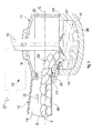
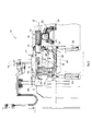
図3〜図5において、金属材料の溶融プラントは、参照番号10として全体が表示され、そして、少なくとも、例えば、スクラップS(図3)といった金属装入物を供給し、一定の移送軸Zに従って移動するのに適している供給手段12を有するアーク炉11を含む。
3 to 5, the metal material melting plant is indicated in its entirety as
スクラップSは、供給手段12上に既知の方法で装荷され、大きく変更も可能であるが一定のサイズを有する。 The scrap S is loaded on the supply means 12 by a known method and can be largely changed, but has a certain size.
炉11は、その主要部分において、容器またはシェル13、およびシェル13の上部にかつ覆うように配置された天井15を備える。
3つの孔が天井15に形成されており、3つの電極16を収納および/または配置し、それらはシェル13に存在する金属装入物にアークを生成するのに適したものである。
The
Three holes are formed in the
天井15および電極16(図5)は、互いに独立して、天井15および電極16を持上げるのに適した、持上げおよび回転デバイス24と連動する。
The
溶融ステップの際に達する高温と、反応性の高い環境に耐えるため、シェル13(図5)は、それぞれが耐火材でできている、底部またはソール36、および外側壁37(直立壁(upright)とも呼ばれる)を備えている。 In order to withstand the high temperatures reached during the melting step and the reactive environment, the shell 13 (FIG. 5) consists of a bottom or sole 36 and an outer wall 37 (upright), each made of refractory material. Also called).
シェル13は、そこに収容可能な、液体金属および場合によってはスラグの最大量を決定する深さD(図5)を有する。
The
シェル13(図5)は、支持体(図示されない)に取付けられ、そして、駆動手段28が、一定の回転軸Cを中心にしてシェル13を回転させるために設けられている。
The shell 13 (FIG. 5) is attached to a support (not shown), and drive means 28 are provided for rotating the
回転軸Cは、実質的に、供給手段12の移送軸Zと整列するか、またはすぐ近くに配置される。 The rotation axis C is substantially aligned with or immediately adjacent to the transfer axis Z of the supply means 12.
また、上記炉11はパネル22を備え、パネル22の下端部は、シェル13の上端部の上に載っている。パネル22は、実質的にシェル13の壁に沿って延伸し、そして、その上に、シェル13を閉じるために、天井15が配置されている。
The
シェル13およびパネル22は、共通の接続端部に近接して、熱分散および/またはガス漏れを防止するのに適した密封手段(図示されない)を備える。
The
スクラップSを供給するために、パネル22は、供給手段12が配置される開口部17を備えている。
In order to supply the scrap S, the
炉11が通常動作している際には、供給手段12は、パネル22およびシェル13の壁と実質的に面一にそれらの搬出端部が配置されている。
When the
パネル22の高さは開口部17自体と相関しており、そして、それは、供給手段12または供給手段12によって供給されるスクラップSの供給量によって、大きさが設定される。また、パネル22の開口部17の構造および配置は、鋳造プロセスの間にシェル13が受ける動きに関連して、決定される。
The height of the
より詳しくは、シェル13の回転軸Cと供給手段12の移送軸Zとが、整列または実質的に整列する条件を考慮して、開口部17の配置が定められる。
More specifically, the arrangement of the
この条件により、供給手段12を後退させる必要なく、溶融金属の出湯またはスラッギングの実行が可能となる。そうすると、出湯が終わるとすぐに、アークのスイッチが入るのを待つ必要なく装荷作業を開始できるので、処理時間を短縮できる。 Under this condition, it is possible to perform molten metal pouring or slugging without the need to retract the supply means 12. Then, as soon as the hot water is finished, the loading operation can be started without waiting for the arc to be switched on, so that the processing time can be shortened.
特に開口部17は、パネル22の下端部28から距離をおかれ、いくつかの実施例においては、その距離は、シェル13の深さDの0.3〜3倍、好ましくは0.5〜1.5倍、より好ましくは0.5〜2.5倍の一定の高さFである。
In particular, the
高さFに含まれるパネル22の部分は、供給手段12(今後更に詳細に記載)によって装荷されるスクラップSを収容する機能を有する。
The portion of the
熱交換手段(この場合は、冷却パネルなどのチューブの束を有する交換器)は、高温であってもそれらの機械抵抗を保証するために、パネル22および天井15に連結している。
The heat exchanging means (in this case, an exchanger having a bundle of tubes such as cooling panels) is connected to the
シェル13の回転軸Cと供給手段12の移送軸Zとが前記整列条件となるように、供給手段12は、出湯およびスラッギングの際に、干渉することなく、シェル13を回転させるのに適した構造となっている。
The supply means 12 is suitable for rotating the
特に、供給手段12(図3〜5)は、後述の処理パラメータに従って選択的に変わる、一定の供給量Qで、シェル13に向かって前方にスクラップSを移動させる振動タイプのコンベヤ14を備える。
In particular, the supply means 12 (FIGS. 3 to 5) includes a
コンベヤ14は、平坦な底部40を有する実質的に台形の移送部を有し、そして、スクラップSが積み降ろされる端部は、開口部17(図5)の下端部から、一定の距離Eをおいて配置される。
The
実施例の他の形において、上記底部40は、スクラップSを収容する表面に向かって凹面でもよい。 In another form of embodiment, the bottom 40 may be concave toward the surface that houses the scrap S.
さらに、コンベヤ14の末端部は、振動デバイス23(図5)および位置決めデバイス25(部分的に図面に示される)によって操作されるトロリーに取付けられる。
Furthermore, the distal end of the
位置決めデバイス25(この場合油圧アクチュエータ)は、シェル13にスクラップSを積み降ろすためにパネル22の開口部17へ、そして開口部17から、トロリー、およびそれとともにコンベヤ14を移動させるのに適している。
The positioning device 25 (in this case a hydraulic actuator) is suitable for moving the trolley and with it the
コンベヤ14を、炉11へ、そして炉11から水平方向に移動させることが可能であり、コンベヤ14は常にシェル13に対して同じ高さに位置する。
The
コンベヤ14、もしくは振動デバイス23は、運転制御デバイス27(図3)により制御されており、シェル13へ運搬され、その中に導入されるスクラップSの供給量Qを調整するのに適する。
The
実施例の他の形において、例えばベルトコンベヤといった他の種類の供給手段を設けても良い。 In other forms of embodiments, other types of feeding means may be provided, for example a belt conveyor.
補助エネルギー供給手段20(この場合バーナー)は、更なる熱エネルギーを供給する機能を備え、下部端28と開口部17の下部端との間で、パネル22に取付けられる。
The auxiliary energy supply means 20 (in this case, the burner) has a function of supplying further heat energy, and is attached to the
特に、バーナー20(図4)(この場合4個)は、スクラップSが降ろされる側付近のパネル22に結合されて、実質的に高さFの中心線の近くに配置される。
In particular, the burners 20 (FIG. 4) (four in this case) are coupled to the
また、酸素吹込手段21あるいはランスが、既知の方法で設けられ、液体の組成物から不要な元素を除去するために、鋼のバスに酸素を注入することができる。 Also, oxygen blowing means 21 or lances are provided in a known manner, and oxygen can be injected into the steel bath to remove unwanted elements from the liquid composition.
本発明による溶融法は、プラント10を開始させるステップを有し、そのステップでは、供給手段12が炉11に装荷し、シェル13の底部またはソール上に均等にスクラップSを配置する。
The melting method according to the invention has a step of starting the
上記開始ステップは、従来技術で説明したバスケットを使用して実行することも可能である。この場合、天井15および電極16は、シェル13に対して上昇し、横方向にずれて、バスケットが到達できるようにする。
The starting step can also be performed using the basket described in the prior art. In this case, the
その後、(図3および4)、天井15がシェル13を閉じるために用いられ、電極16が位置決めされて、天井15に作られた孔を介して挿入され、そして、金属装入物の溶融が開始し、溶融金属のホットヒールの一定の液面レベルH(図3)を形成する。この場合、そのレベルは、タップツータップ間で連続的に維持されるホット−ヒールの液面レベルHに、実質的に等しい。
Thereafter (FIGS. 3 and 4), the
プラント10が通常の作動状態に達するとき、出湯と次の出湯との間の、シェル13内のホットヒール(hot heel)Hのレベルは、出湯前の液体金属の総量の約10%〜25%の範囲に維持される。
When the
プラント10を同じ生産能力(この場合約130t/h)とし、従来技術を示すグラフ(図1)と本発明により得られたグラフ(図2)とを比較すると分かるように、ホットヒール(hot heel)Hのレベルは実質的に半分となり、その結果、生産性を向上する。
As the
溶融金属の出湯ステップの後(すなわち出湯ステップの直後に)、本発明の方法は、スクラップSの連続装荷のステップ、電極16に電力を供給(電源オン状態)する、同時または少なくとも一部同時のステップ、それゆえ結果的に金属装入物を溶融させるステップを提供する。 After the molten metal pouring step (ie, immediately after the pouring step), the method of the present invention includes a step of continuously loading scrap S, supplying power to the electrode 16 (powered on), simultaneously or at least partially simultaneously. Providing a step, and consequently a step of melting the metal charge.
供給手段12が、出湯またはスラッギングステップの間も、作動位置にそのまま維持される実施例の形において、そして、これらのステップの1つが終わるとすぐに、供給手段12は炉11への供給を直ちに再開することができ、故に、電源オン状態に先行する。
In the form of an embodiment in which the supply means 12 remains in the operating position during the tapping or slugging step, and as soon as one of these steps is over, the supply means 12 immediately supplies the
金属装入物の溶融を完了するために、電力の供給は中断され、電源オフ状態となり、そして、出湯または鋳造ステップが設けられる。 To complete the melting of the metal charge, the power supply is interrupted, the power is turned off, and a tapping or casting step is provided.
これらのステップの際、まず初めに第1のサブステップ31が設けられ(図2)、そして、少なくとも開口部17付近に、スクラップSの固体塊の蓄積物30を作り出すよう、スクラップS(図3および4)が、シェル13内部に高い供給量で装荷される。
During these steps, a first sub-step 31 is first provided (FIG. 2), and the scrap S (FIG. 3) is created so as to create a solid
蓄積物30は、開口部17に近い高さになる固体材料の塊であり、ほぼコンベヤ14の底部40と同一平面になる。
The
第1のサブステップ31においては、供給手段12は、具体的なスクラップの供給量、約50(kg/min)/MW〜約150(kg/min)/MW、好ましくは約100(kg/min)/MW)で、炉11に供給する。 In the first sub-step 31, the supplying means 12 supplies a specific scrap supply amount of about 50 (kg / min) / MW to about 150 (kg / min) / MW, preferably about 100 (kg / min). ) / MW).
ほんの一例として、約60MWの公称電力を有する炉11において、スクラップSの供給量Qは、約3000kg/min〜約9000kg/min、好ましくは6000kg/min〜約7000kg/min、である。
By way of example only, in a
スクラップSの供給量Qは、電源オンとオフの間(この場合約6分)は、約10%〜20%(好ましくは約13%〜17%)に維持される。 The supply amount Q of the scrap S is maintained at about 10% to 20% (preferably about 13% to 17%) during power on and off (in this case, about 6 minutes).
スクラップSの供給量Qは、コンベヤ14と連動する運転制御デバイス27によって調整される。
The supply amount Q of the scrap S is adjusted by an
この第1のサブステップ31と同時、その間、若しくはその後に、金属の溶融が始まる(電源オン状態)。図2に示す実施例では、金属の溶融は、第1のサブステップ31から約2分遅れて始まる。
At the same time, during or after the first sub-step 31, melting of the metal starts (power-on state). In the embodiment shown in FIG. 2, the melting of the metal begins approximately 2 minutes after the
第1のサブステップ31の後、第2のサブステップ32が設けられており、そして、その間、コンベヤ14によって導入されるスクラップSの量に実質的に応じて、電極16に金属を溶融させるために、スクラップの供給量Qが減少する。
After the first sub-step 31, a second sub-step 32 is provided, during which time the metal is melted at the
第2のサブステップ32の間、スクラップSの供給量Qは、後に出湯される液体金属の全量の25%〜45%(好ましくは30%〜40%、さらにより好ましくは約32%〜約38%)のスクラップの固体塊の量が、鋼の液体バス内で維持されるように、調整される。 During the second sub-step 32, the supply rate Q of the scrap S is 25% to 45% (preferably 30% to 40%, even more preferably about 32% to about 38%) of the total amount of liquid metal to be discharged later. %) Of the solid mass of scrap is adjusted to be maintained in the steel liquid bath.
スクラップSの具体的な供給量は、約75(kg/min)/MW〜約85(kg/min)/MWで、実質的に一定に保たれる。ほんの一例として、約60MWの公称電力を有する炉11で、スクラップSの供給量Qは、約4500kg/min〜5000kg/minである。
A specific supply amount of the scrap S is approximately 75 (kg / min) / MW to approximately 85 (kg / min) / MW, and is kept substantially constant. As just an example, in a
供給されるスクラップの量と溶融する固体塊の量とが平衡する状態が、電源オンとオフとの間(この場合約13分)の、約10%〜20%、好適には約13%〜17%、の間、維持される。 The balance between the amount of scrap fed and the amount of solid mass to melt is about 10% to 20%, preferably about 13%, between power on and off (in this case about 13 minutes) Maintained for 17%.
溶鋼に含まれる固体塊は、畜熱器(「熱はずみ車」とも呼ばれる)として機能し、そして、すでに溶融している鋼を、従来技術で達成している温度より低い温度で保つことができる。 The solid mass contained in the molten steel functions as a livestock heater (also called a “heat flywheel”) and can keep the already molten steel at a temperature lower than that achieved in the prior art.
溶融した鋼を低い温度で保つと、シェルの壁の摩耗現象を低減するようバスを安定した状態に保ち、それ故、回復させるための保守作業の頻度を減少する。 Keeping the molten steel at a low temperature keeps the bath stable so as to reduce the wear phenomenon of the shell wall and therefore reduces the frequency of maintenance work to recover.
その後、炉の装荷が最大値近くに達するとき、第3のサブステップ33(図2)において、スクラップの供給量Qを減少させ、この場合最初に半分に、その後、実質的に中断されるか、そうでなくても最小値に保たれる。このようにして、液体に存在する全ての固体塊は、溶融される。 Thereafter, when the furnace load reaches near the maximum value, in the third sub-step 33 (FIG. 2), the scrap supply Q is reduced, in this case first half and then substantially interrupted. Otherwise, it is kept at the minimum value. In this way, all the solid mass present in the liquid is melted.
第3のサブステップ33終了後、装荷は完全に停止され、そして、固体金属全てが液状となる。 After completion of the third sub-step 33, the loading is completely stopped and all the solid metal becomes liquid.
既知の方法では、第3のサブステップ33の間、もしくはその後に、溶融金属のバスの所望の熱的、および化学的特性を確定するために、溶鋼を過熱するステップも設けられている。 In the known method, a step of superheating the molten steel is also provided during or after the third sub-step 33 in order to determine the desired thermal and chemical properties of the molten metal bath.
第1のサブステップ31と第3のサブステップ33との間、もしくはこれらのサブステップ中に、バーナー20を使用した、補助熱エネルギーの供給も設けられている。
A supplementary heat energy supply using a
バーナー20はパネル22と結合しているので、スクラップSの蓄積物30から近い位置で、直射的な炎で直接スクラップSを加熱する。
Since the
さらにまた、スクラップSの蓄積物30は、少なくとも第2のサブステップ32間、実質的に一定の高さであり、これにより、もしものハネ、または、高温の液体金属に対するバリアとして機能し、結果として実用寿命を延ばし、更に固体の蓄積物30にバーナー20を近づけることを可能にする。この全ては、それぞれ、必要とされるバーナー20のメンテナンス回数を減少させ、バーナー20の効率を上げるという利点がある。
Furthermore, the
第2および第3のステップの間、上記機能を備えた酸素注入作業、酸化鉄の産出を抑えるために炭素を供給する作業、および、スラグの組成物を改質して、脱燐プロセスを可能にするためにライムおよびマグネサイトを供給する作業が行われる。 During the second and third steps, the oxygen injection operation with the above functions, the operation of supplying carbon to suppress the production of iron oxide, and the slag composition can be modified to enable the dephosphorization process The work to supply lime and magnesite is performed.
さらにまた、少なくとも第2および第3のステップ間、スラグの量を増加させるために添加物が加えられる(別名スラグフォーミング)。それにより、金属バスが酸化するのを保護し、更に溶融バスや電極16の、アークによって発生する輻射エネルギーを遮断する効果が得られる。
Furthermore, additives are added to increase the amount of slag (also known as slag forming) at least during the second and third steps. Thereby, it is possible to protect the metal bath from being oxidized, and to obtain an effect of blocking the radiation energy generated by the arc of the melting bath and the
第3のステップ終了後、電力の供給は、中断され(電源オフ状態)、シェル13の傾斜(別名チルティング)によって溶融した鋼を出湯するステップがある。 After the third step, the supply of electric power is interrupted (power is turned off), and there is a step of pouring molten steel by the inclination of the shell 13 (aka tilting).
そこに残されるホットヒール(hot heel)Hが、上で特定された一定のレベルとなるまで、出湯ステップはシェル13を回転させる。
The hot water step rotates the
実行するプロセスに応じて、出湯ステップと反対方向にシェル13を回転させ、出湯ステップ中かその前に、スラグ除去(別名スラッギング)を実行することも可能である。これに対して、シェル13がスラッギングのために回転するのではなく、スラグをシェル13に保持するために反対側に傾けられる場合、本発明の炉11は、スクラップSを装荷するために使用する開口部17からあふれ出ないので、より多くの容量のスラグを保持するのを可能にする。
Depending on the process to be performed, it is also possible to rotate the
一旦出湯作業が終了すると、出湯口は閉じられ、そして、シェル13は回転により平常位置に戻される。
Once the pouring operation is completed, the pouring gate is closed, and the
この最後の作業の間、コンベヤ14がシェル13内部でその位置のままであるならば、スクラップSの装荷をすぐに、従って出湯動作の直後に、開始することが可能である。これにより休止時間を大幅に減少し、ホットヒール(hot heel)の鋼にキリングアクションを実施するのを可能にする。
During this last operation, if the
本発明の分野および範囲を逸脱しない範囲で、これまで記載されているような、金属材料を溶融させる方法に対して、部品を変更および/または追加することが可能であるのは明白である。 Obviously, it is possible to modify and / or add parts to the method of melting a metallic material as described so far without departing from the field and scope of the present invention.
本発明について、いくつかの具体例に関して記載したが、当業者ならば、請求項にて説明するような特性を有する、金属材料を溶融させる方法の、他の多くの同等な形態に確実に到達することが可能であることは明白であり、それ故、すべてがここに定義される保護範囲となることも明白である。 Although the present invention has been described in terms of several embodiments, those skilled in the art will certainly reach many other equivalent forms of a method of melting a metal material having the characteristics as set forth in the claims. It is clear that it is possible to do so, and therefore it is also clear that everything is within the scope of protection defined herein.
Claims (12)
前記装荷および溶融する方法は、
前記供給手段(12)によって前記金属材料(S)を前記シェル(13)に装荷するステップと、
前記金属材料(S)を溶融させる装荷および溶融する溶融ステップと、
溶融金属材料が出湯される出湯ステップとを、少なくとも含み、
前記装荷ステップの間、少なくとも、出湯の前に前記炉に含まれており、溶融サイクルの終わりに出湯される溶融した材料の全体量の25%〜45%の固体材料の最初の蓄積物(30)を前記シェル(13)内部で生成するように、前記金属材料(S)を、前記シェル(13)内部に装荷する第1の装荷サブステップ(31)と、
少なくとも、次の第2の装荷および溶融サブステップ(32)であって、徐々に形成されるメタルバス内部で、前記最初の蓄積物(30)を定める前記金属材料(S)の量と実質的に等しい、前記金属材料(S)の固体の量を保持するために、
前記第2の装荷および溶融サブステップにおいて電気炉(11)に装入される金属材料の供給量(Q)が、溶融される金属材料の量に実質的に対応するよう、制御デバイス(27)によって、シェル(13)におろされる前記金属材料(S)の供給量(Q)を減少させる、第2の装荷および溶融サブステップ(32)と、
炉に存在する全ての金属材料を完全に溶融させ、全ての固体塊が溶融すると出湯ステップを実行するために、装荷プロセスが止まるまで、供給量を更に減少させる第3のサブステップ(33)と、が設けられていることを特徴とする方法。 A melting plant comprising at least one electric furnace (11) having a shell (13) into which a metal material is introduced, and supply means (12) for loading the metal material (S) onto the shell (13) A method for loading and melting a metallic material (S) of
The method of loading and melting includes:
Loading the metal material (S) onto the shell (13) by the supply means (12);
Loading for melting the metal material (S) and melting step for melting;
At least a hot water step in which the molten metal material is poured,
During the loading step, at least an initial accumulation of solid material (30% to 45% of the total amount of molten material contained in the furnace prior to tapping and tapped at the end of the melting cycle (30 ) In the shell (13), the first loading sub-step (31) loading the metal material (S) into the shell (13);
At least a second loading and melting sub-step (32), substantially within the gradually formed metal bath, substantially equal to the amount of the metallic material (S) defining the first deposit (30) To maintain a solid amount of the metal material (S) equal to
The control device (27) so that the supply amount (Q) of the metal material charged into the electric furnace (11) in the second loading and melting substep substantially corresponds to the amount of metal material to be melted. A second loading and melting substep (32), which reduces the supply (Q) of the metal material (S) that is put into the shell (13) by:
A third sub-step (33) that further reduces the feed rate until the loading process stops to completely melt all metal material present in the furnace and perform the tapping step when all solid mass has melted; A method characterized in that is provided.
燃焼型補助加熱エネルギー供給手段(20)によって、補助熱エネルギーが供給されることを特徴とする、請求項1に記載の方法。 At least between the first loading sub-step (31) and the second loading and melting sub-step (32) and / or during these sub-steps,
2. A method according to claim 1, characterized in that auxiliary heat energy is supplied by the combustion type auxiliary heating energy supply means (20).
前記プラントは、
前記シェル(13)内部の固体材料の最初の蓄積物(30)をまず決定し、その後、徐々に形成されるメタルバス内部で、前記最初の蓄積物(30)を定める金属材料(S)の量に実質的に等しい前記金属材料(S)の固体塊の量を維持するために、
前記供給手段(12)の供給量Qを調整する制御デバイス(27)をさらに備え、
前記炉はまた、前記シェル(13)を覆うための前記炉とは分離する被覆要素(15)と、前記シェル(13)と前記被覆要素(15)との間に配置されるパネル(22)とを備え、
前記パネル(22)には前記供給手段(12)が配置可能な開口(17)が設けられており、
前記シェル(13)は深さ(D)を有し、
前記開口(17)は、前記シェル(13)の深さ(D)の0.3〜3倍の所定の高さ(F)だけ、パネル(22)の下部端(28)から距離をおいて作られる、プラント。 The method according to claim 1, comprising an electric furnace (11) having a shell (13) into which a metallic material is introduced, and a supply means (12) for loading said metallic material (S) onto said shell (13). A plant for melting the metal material (S),
The plant is
The first accumulation (30) of solid material inside the shell (13) is first determined, and then the metal material (S) defining the first accumulation (30) within the gradually formed metal bath. In order to maintain a solid mass quantity of the metal material (S) substantially equal to the quantity,
A control device (27) for adjusting the supply amount Q of the supply means (12);
The furnace also includes a covering element (15) separate from the furnace for covering the shell (13), and a panel (22) disposed between the shell (13) and the covering element (15). And
The panel (22) is provided with an opening (17) in which the supply means (12) can be arranged,
The shell (13) has a depth (D);
The opening (17) is spaced from the lower end (28) of the panel (22) by a predetermined height (F) of 0.3 to 3 times the depth (D) of the shell (13). A plant that is made.
Applications Claiming Priority (3)
| Application Number | Priority Date | Filing Date | Title |
|---|---|---|---|
| ITUD2013A000052 | 2013-04-23 | ||
| IT000052A ITUD20130052A1 (en) | 2013-04-23 | 2013-04-23 | PROCEDURE FOR THE FUSION OF METAL MATERIAL IN A MERGER PLANT AND ITS RELATION MERGER PLANT |
| PCT/IB2014/060942 WO2014174463A2 (en) | 2013-04-23 | 2014-04-23 | Method for melting metal material in a melting plant and relative melting plant |
Publications (2)
| Publication Number | Publication Date |
|---|---|
| JP2016521317A JP2016521317A (en) | 2016-07-21 |
| JP6203376B2 true JP6203376B2 (en) | 2017-09-27 |
Family
ID=48485380
Family Applications (1)
| Application Number | Title | Priority Date | Filing Date |
|---|---|---|---|
| JP2016509586A Active JP6203376B2 (en) | 2013-04-23 | 2014-04-23 | Method for melting metal material in melting plant and melting plant |
Country Status (9)
| Country | Link |
|---|---|
| US (1) | US10801083B2 (en) |
| EP (1) | EP2989402B1 (en) |
| JP (1) | JP6203376B2 (en) |
| KR (1) | KR20160003757A (en) |
| CN (1) | CN105612398B (en) |
| IT (1) | ITUD20130052A1 (en) |
| MX (1) | MX366349B (en) |
| RU (1) | RU2639078C2 (en) |
| WO (1) | WO2014174463A2 (en) |
Families Citing this family (2)
| Publication number | Priority date | Publication date | Assignee | Title |
|---|---|---|---|---|
| IT201700109681A1 (en) * | 2017-09-29 | 2019-03-29 | Danieli Off Mecc | APPARATUS AND METHOD OF MELTING METAL MATERIAL |
| IT201800004846A1 (en) * | 2018-04-24 | 2019-10-24 | METHOD OF ELECTRIC POWER SUPPLY OF AN ELECTRIC ARC OVEN AND RELATED APPARATUS |
Family Cites Families (17)
| Publication number | Priority date | Publication date | Assignee | Title |
|---|---|---|---|---|
| FR2236942A1 (en) * | 1973-07-13 | 1975-02-07 | Siderurgie Fse Inst Rech | Continuous melting of iron-bearing matls. in an arc furnace - using controlled height of slag and charge for low power consumption |
| JP2500746Y2 (en) * | 1991-09-12 | 1996-06-12 | 新日本製鐵株式会社 | Continuous charging equipment for electric furnace |
| JPH07190629A (en) * | 1993-04-15 | 1995-07-28 | Ishikawajima Harima Heavy Ind Co Ltd | Scrap material preheating and charging device |
| JPH07286208A (en) * | 1994-04-15 | 1995-10-31 | Nippon Steel Corp | Operating method of continuous scrap charging type arc furnace |
| IT1280115B1 (en) * | 1995-01-17 | 1998-01-05 | Danieli Off Mecc | MELTING PROCEDURE FOR ELECTRIC ARC OVEN WITH ALTERNATIVE SOURCES OF ENERGY AND RELATED ELECTRIC ARC OVEN |
| US5654976A (en) * | 1995-04-18 | 1997-08-05 | Elkem Technology A/S | Method for melting ferrous scrap metal and chromite in a submerged arc furnace to produce a chromium containing iron |
| AT404942B (en) * | 1997-06-27 | 1999-03-25 | Voest Alpine Ind Anlagen | PLANT AND METHOD FOR PRODUCING METAL MELT |
| US6024912A (en) * | 1997-11-27 | 2000-02-15 | Empco (Canada) Ltd. | Apparatus and process system for preheating of steel scrap for melting metallurgical furnaces with concurrent flow of scrap and heating gases |
| US6155333A (en) * | 1999-02-23 | 2000-12-05 | Techint Compagnia Tecnica Internazionale | Continuous electric steelmaking with charge preheating, melting, refining and casting |
| CN1264996C (en) * | 1999-06-25 | 2006-07-19 | 泰斯特·卡姆帕尼亚国际技术公开有限公司 | Method and apparatus for electric steel production having continuously preheating, smelting, refining and casting processes |
| EP1114973A4 (en) * | 1999-07-08 | 2004-12-29 | Jp Steel Plantech Co | Equipment and method for arc melting of cold pig iron source |
| WO2003095685A1 (en) * | 2002-05-10 | 2003-11-20 | Sms Demag Ag | Scrap charger |
| ITMI20050626A1 (en) * | 2005-04-13 | 2006-10-14 | Technit Compagnia Tecnica Inte | APPARATUS FOR MEASURING AND MONITORING THE FEEDING OF CHARGING OR SCRAPPING MATERIAL AT A OVEN AND ITS PROCEDURE |
| CN102031328B (en) * | 2009-09-30 | 2012-06-13 | 鞍钢股份有限公司 | Loading method of converter |
| JP5909957B2 (en) * | 2010-09-29 | 2016-04-27 | Jfeスチール株式会社 | Steel making method using steel scrap |
| US9294717B2 (en) * | 2010-10-13 | 2016-03-22 | At&T Intellectual Property I, L.P. | System and method to enable layered video messaging |
| CN102003876B (en) * | 2010-11-16 | 2012-12-05 | 中冶赛迪工程技术股份有限公司 | Culvert raw material delivery and smoke dust recovery device |
-
2013
- 2013-04-23 IT IT000052A patent/ITUD20130052A1/en unknown
-
2014
- 2014-04-23 JP JP2016509586A patent/JP6203376B2/en active Active
- 2014-04-23 EP EP14728322.0A patent/EP2989402B1/en active Active
- 2014-04-23 RU RU2015149935A patent/RU2639078C2/en active
- 2014-04-23 US US14/786,152 patent/US10801083B2/en active Active
- 2014-04-23 MX MX2015014824A patent/MX366349B/en active IP Right Grant
- 2014-04-23 WO PCT/IB2014/060942 patent/WO2014174463A2/en active Application Filing
- 2014-04-23 CN CN201480035671.XA patent/CN105612398B/en active Active
- 2014-04-23 KR KR1020157033375A patent/KR20160003757A/en active Search and Examination
Also Published As
| Publication number | Publication date |
|---|---|
| EP2989402A2 (en) | 2016-03-02 |
| RU2015149935A (en) | 2017-05-26 |
| CN105612398B (en) | 2018-01-19 |
| MX366349B (en) | 2019-07-05 |
| ITUD20130052A1 (en) | 2014-10-24 |
| US10801083B2 (en) | 2020-10-13 |
| EP2989402B1 (en) | 2019-02-20 |
| KR20160003757A (en) | 2016-01-11 |
| JP2016521317A (en) | 2016-07-21 |
| WO2014174463A3 (en) | 2015-02-26 |
| RU2639078C2 (en) | 2017-12-19 |
| WO2014174463A2 (en) | 2014-10-30 |
| MX2015014824A (en) | 2016-06-21 |
| CN105612398A (en) | 2016-05-25 |
| US20160076114A1 (en) | 2016-03-17 |
Similar Documents
| Publication | Publication Date | Title |
|---|---|---|
| CA2449774C (en) | Method for melting and decarburization of iron carbon melts | |
| US20070267787A1 (en) | Methods of implementing a water-cooling system into a burner panel and related apparatuses | |
| JP6203376B2 (en) | Method for melting metal material in melting plant and melting plant | |
| US5117438A (en) | Method of operating a smelting unit and smelting unit for that method | |
| JP3721154B2 (en) | Method for refining molten metal containing chromium | |
| JP3204202B2 (en) | Melting method and melting equipment for cold iron source | |
| JP3699586B2 (en) | Method and apparatus for melting iron scrap | |
| JPH11257859A (en) | Method for melting cold iron source and melting facility | |
| JP5411466B2 (en) | Iron bath melting furnace and method for producing molten iron using the same | |
| JP2000017319A (en) | Operation of arc furnace | |
| JP2001074377A (en) | Method and facility for melting cold iron source | |
| JP3521277B2 (en) | Cold iron source melting method and melting equipment | |
| RU2420597C1 (en) | Procedure for melting steel in arc steel melting furnace of three phase current | |
| JPH11344287A (en) | Operation of arc furnace | |
| JP3546843B2 (en) | Arc electric furnace for steelmaking | |
| JPH10310814A (en) | Method for melting cold iron source and melting equipment thereof | |
| KR100945140B1 (en) | Sub-material supply apparatus merely operation of minimizing cold spot of minimil electric furnace | |
| JP2002206859A (en) | Melting equipment of cold iron | |
| JP2002121611A (en) | Method and apparatus for melting cold iron | |
| JP3114713B2 (en) | Arc melting equipment and melting method for cold iron source | |
| JP2000111270A (en) | Method for melting cold iron source | |
| JPH02238290A (en) | Arc electric furnace | |
| JP2002053908A (en) | Facility and method for melting cold iron source | |
| JP2004251531A (en) | Arc melting furnace of cold iron source | |
| JPH0593219A (en) | Method and device for heating vacuum degassing treatment vessel |
Legal Events
| Date | Code | Title | Description |
|---|---|---|---|
| A977 | Report on retrieval |
Free format text: JAPANESE INTERMEDIATE CODE: A971007 Effective date: 20161221 |
|
| A131 | Notification of reasons for refusal |
Free format text: JAPANESE INTERMEDIATE CODE: A131 Effective date: 20170131 |
|
| A601 | Written request for extension of time |
Free format text: JAPANESE INTERMEDIATE CODE: A601 Effective date: 20170428 |
|
| A521 | Request for written amendment filed |
Free format text: JAPANESE INTERMEDIATE CODE: A523 Effective date: 20170629 |
|
| TRDD | Decision of grant or rejection written | ||
| A01 | Written decision to grant a patent or to grant a registration (utility model) |
Free format text: JAPANESE INTERMEDIATE CODE: A01 Effective date: 20170808 |
|
| A61 | First payment of annual fees (during grant procedure) |
Free format text: JAPANESE INTERMEDIATE CODE: A61 Effective date: 20170829 |
|
| R150 | Certificate of patent or registration of utility model |
Ref document number: 6203376 Country of ref document: JP Free format text: JAPANESE INTERMEDIATE CODE: R150 |
|
| R250 | Receipt of annual fees |
Free format text: JAPANESE INTERMEDIATE CODE: R250 |
|
| R250 | Receipt of annual fees |
Free format text: JAPANESE INTERMEDIATE CODE: R250 |
|
| R250 | Receipt of annual fees |
Free format text: JAPANESE INTERMEDIATE CODE: R250 |
|
| R250 | Receipt of annual fees |
Free format text: JAPANESE INTERMEDIATE CODE: R250 |