JP6202856B2 - Image processing apparatus, image processing method, and program - Google Patents
Image processing apparatus, image processing method, and program Download PDFInfo
- Publication number
- JP6202856B2 JP6202856B2 JP2013076145A JP2013076145A JP6202856B2 JP 6202856 B2 JP6202856 B2 JP 6202856B2 JP 2013076145 A JP2013076145 A JP 2013076145A JP 2013076145 A JP2013076145 A JP 2013076145A JP 6202856 B2 JP6202856 B2 JP 6202856B2
- Authority
- JP
- Japan
- Prior art keywords
- image
- color correction
- color
- glasses
- crosstalk
- Prior art date
- Legal status (The legal status is an assumption and is not a legal conclusion. Google has not performed a legal analysis and makes no representation as to the accuracy of the status listed.)
- Active
Links
Images


Classifications
-
- H—ELECTRICITY
- H04—ELECTRIC COMMUNICATION TECHNIQUE
- H04N—PICTORIAL COMMUNICATION, e.g. TELEVISION
- H04N13/00—Stereoscopic video systems; Multi-view video systems; Details thereof
- H04N13/30—Image reproducers
- H04N13/324—Colour aspects
-
- H—ELECTRICITY
- H04—ELECTRIC COMMUNICATION TECHNIQUE
- H04N—PICTORIAL COMMUNICATION, e.g. TELEVISION
- H04N13/00—Stereoscopic video systems; Multi-view video systems; Details thereof
- H04N13/10—Processing, recording or transmission of stereoscopic or multi-view image signals
- H04N13/106—Processing image signals
- H04N13/15—Processing image signals for colour aspects of image signals
-
- H—ELECTRICITY
- H04—ELECTRIC COMMUNICATION TECHNIQUE
- H04N—PICTORIAL COMMUNICATION, e.g. TELEVISION
- H04N13/00—Stereoscopic video systems; Multi-view video systems; Details thereof
- H04N13/30—Image reproducers
- H04N13/332—Displays for viewing with the aid of special glasses or head-mounted displays [HMD]
- H04N13/337—Displays for viewing with the aid of special glasses or head-mounted displays [HMD] using polarisation multiplexing
Landscapes
- Engineering & Computer Science (AREA)
- Multimedia (AREA)
- Signal Processing (AREA)
- Controls And Circuits For Display Device (AREA)
- Testing, Inspecting, Measuring Of Stereoscopic Televisions And Televisions (AREA)
Description
本発明は、画像表示技術における色補正処理に関する。 The present invention relates to color correction processing in image display technology.
現在、両眼視差を利用して観賞者に立体像を知覚させる3D画像表示技術が普及している。この技術は、同一物体に関して両眼の視差の分だけ見え方の異なる画像(視差画像)を左右それぞれの眼に別個に提示することにより立体像を知覚させる技術である。中でも専用のメガネを併用する方式(以下、「メガネ方式」と呼ぶ。)は、映画館の3D上映や家庭用3Dテレビで採用され広く知られている。このようなメガネ方式の3D画像表示技術のうち例えば偏光メガネ方式では、LCDパネルなどの画像出力装置により視差画像を偏光で出力し、この出力光を、偏光板を取り付けたメガネを用いて左右の眼に振り分けることで、それぞれの眼に視差画像が提示される。 Currently, 3D image display technology that allows viewers to perceive a stereoscopic image using binocular parallax is widespread. This technique is a technique for perceiving a stereoscopic image by separately presenting to the left and right eyes images (parallax images) that differ in appearance by the amount of parallax between both eyes with respect to the same object. Among them, a method of using dedicated glasses (hereinafter referred to as “glasses method”) is widely known and adopted for 3D screening in movie theaters and 3D televisions for home use. Among such glasses-type 3D image display technologies, for example, in the polarized glasses method, a parallax image is output as polarized light by an image output device such as an LCD panel, and this output light is output to the left and right using glasses equipped with polarizing plates. By distributing to the eyes, a parallax image is presented to each eye.
また、偏光メガネは、複数人の観賞者に対して同一画面を用いて同時に異なる画像を提示する同時マルチ画像表示技術においても用いられる。この場合は、メガネごとに特性の異なる偏光板を取り付け、偏光で出力した画像をそれぞれのメガネをかけた観賞者に振り分けることで、各観賞者に異なる画像が提示される。 Polarized glasses are also used in a simultaneous multi-image display technique in which different images are simultaneously presented to a plurality of viewers using the same screen. In this case, a polarizing plate having different characteristics is attached to each pair of glasses, and an image output by polarized light is distributed to each viewer wearing the respective glasses, whereby a different image is presented to each viewer.
一般にこのようなメガネ方式の画像表示方式の場合、画像出力装置の視野角特性とメガネの光学特性により、観賞位置に依存して色の見え方に変化が生じてしまう。例えば、液晶テレビ等の画像が表示される面(画像表示面)を正面から見た場合と斜めから見た場合とでは、同じ出力画像であってもその色が異なって見えてしまう。このような鑑賞位置に依存した色の変化を抑制する方法としては、視線方向に応じて画像出力装置の色再現を補正する技術が知られている。例えば、特許文献1には、画像表示面に対する観賞者の視線方向を推定し、その視線方向に応じて表示する画像の彩度や明度を補正することにより、視野角特性による色の変化を抑制する技術が開示されている。
In general, in the case of such an eyeglass-type image display method, the color appearance changes depending on the viewing position due to the viewing angle characteristics of the image output device and the optical characteristics of the glasses. For example, when the surface (image display surface) on which an image is displayed, such as a liquid crystal television, is viewed from the front and when viewed from an oblique direction, the same output image appears differently. As a method for suppressing such a color change depending on the viewing position, a technique for correcting the color reproduction of the image output apparatus in accordance with the line-of-sight direction is known. For example,
しかしながら、メガネ方式の画像表示技術における色の見え方の変化は、鑑賞位置だけに依存するものではなく、鑑賞時の姿勢にも依存することが分かっている。例えば、背筋を伸ばして見た場合と首を傾げて見た場合とでは色が異なって見えてしまう。上述の特許文献1の技術は視線方向と画像表示面の法線方向とのなす角度に応じて色補正を行うものであるため、このような鑑賞者の姿勢に依存した色の見え方の変化(視線方向を回転中心としたメガネの傾きによる色の変化)には対応することができなかった。
However, it has been found that the change in the color appearance in the glasses-type image display technology does not depend only on the viewing position but also on the posture during viewing. For example, the colors appear different when viewed with the back straight and when tilted. Since the technique disclosed in
本発明に係る画像処理装置は、偏光素子を有するメガネと画像表示装置とを含む画像表示システムのための画像処理装置であって、前記画像表示装置の表示面に対する前記メガネの傾き情報に基づき、表示される画像を示す画像データに対する色補正処理を行う色補正手段と、を備え、前記色補正手段は、複数の回転角度に対応付けられた複数の色補正パラメータの中から、前記メガネの傾き情報に基づいて、前記色補正処理に用いる色補正パラメータを取得することを特徴とする。 An image processing apparatus according to the present invention is an image processing apparatus for an image display system including glasses having polarizing elements and an image display apparatus, and is based on tilt information of the glasses with respect to a display surface of the image display apparatus. Color correction means for performing color correction processing on image data indicating an image to be displayed , wherein the color correction means is configured to determine the inclination of the glasses from among a plurality of color correction parameters associated with a plurality of rotation angles. Based on the information, a color correction parameter used in the color correction process is acquired .
本発明によれば、メガネ方式の画像表示技術において、メガネの傾きに応じて適切に色再現がなされた画像の表示が可能となる。 According to the present invention, it is possible to display an image in which color reproduction is appropriately performed according to the inclination of the glasses in the glasses-type image display technology.
[実施例1]
本実施例では、画像出力装置の画像表示面上に表示される画像データに対し、メガネの傾きに応じた色補正パラメータを用いて色補正(色変換)処理を施すことにより、適切に色再現がなされた補正画像データを生成する。
[Example 1]
In this embodiment, image data displayed on the image display surface of the image output apparatus is subjected to color correction (color conversion) processing using color correction parameters corresponding to the inclination of the glasses, thereby appropriately reproducing colors. The corrected image data subjected to is generated.
図1は、本実施例に係るメガネ方式の3D画像表示技術を採用したシステム構成例を示す図である。 FIG. 1 is a diagram illustrating a system configuration example that employs the glasses-type 3D image display technology according to the present embodiment.
3D画像表示システム100は、入力された画像データに色補正処理を行って補正画像データを生成する画像処理装置110、円偏光板をレンズに用いた専用メガネ120、画像出力装置としての液晶ディスプレイ130で構成される。
The 3D
デジタルカメラ等から入力された3D表示用の画像データが、専用メガネ120に設けられた傾きセンサ121からの情報に応じて画像処理装置110で色補正処理され、それが液晶ディスプレイ130に出力されて表示される。以下、詳しく説明する。
Image data for 3D display input from a digital camera or the like is subjected to color correction processing by the
図2は、画像処理装置110の内部構成を示す図である。
FIG. 2 is a diagram illustrating an internal configuration of the
画像処理装置110は、CPU201、RAM202、ROM203、ハードディスクドライブ(HDD)204、HDD I/F205、入力I/F206、出力I/F207、システムバス208で構成される。
The
CPU201は、RAM202をワークメモリとして、ROM203及びHDD204に格納されたプログラムを実行し、システムバス208を介して後述する各構成を統括的に制御する。これにより、後述する様々な処理が実行される。
The
HDDインタフェイス(I/F)205は、例えばシリアルATA(SATA)等のインタフェイスであり、二次記憶装置としてのHDD204を接続する。CPU201は、HDDI/F205を介して、HDD204からのデータ読み出し、およびHDD204へのデータ書き込みが可能である。さらにCPU201は、HDD204に格納されたデータをRAM202に展開し、同様に、RAM202に展開されたデータをHDD204に保存することが可能である。そしてCPU201は、RAM202に展開したデータをプログラムとみなし、実行することができる。なお、二次記憶装置は、HDDのほか、光ディスクドライブなどの他の記憶デバイスでもよい。
The HDD interface (I / F) 205 is an interface such as serial ATA (SATA), for example, and connects the
入力インタフェイス(I/F)206は、例えばUSBやIEEE1394等のシリアルバスインタフェイスである。入力I/F206は、視差画像を撮像するデジタルカメラ209や、ユーザが各種操作指示を行うためのキーボード・マウス210などの各種入力デバイス、および、加速度センサや角速度センサで構成される傾きセンサ121を接続する。CPU201は、入力I/F206を介して各種入力デバイスや傾きセンサ121から様々なデータを取得することが可能である。なお、デジタルカメラ209は視差画像を撮像可能なデバイスの一例であって、ビデオカメラ等の他のデバイスでもよいことはいうまでもない。
The input interface (I / F) 206 is a serial bus interface such as USB or IEEE1394. The input I /
出力インタフェイス(I/F)207は、例えばDVIやHDMI(登録商標)等の画像出力インタフェイスであり、画像出力装置としての液晶ディスプレイ130を接続する。この出力I/F207を介して液晶ディスプレイ130に画像データが送られ、視差画像が画面上に表示される。なお、図1に示すシステムでは、画像出力装置として液晶ディスプレイ130を用いているが、これに限られない。例えば、液晶ディスプレイに代えてプラズマディスプレイや有機ELディスプレイを用いてもよいし、さらにプロジェクタを用いて視差画像をスクリーンに映し出すタイプのシステムであってもよい。メガネ方式の3D画像表示技術において、本発明は幅広く適用可能である。
An output interface (I / F) 207 is an image output interface such as DVI or HDMI (registered trademark), and connects a
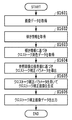
図3は、本実施例に係る画像処理装置110における一連の処理の流れを示すフローチャートである。本実施例では、傾きセンサ121によって、専用メガネ120が基準からどれぐらい傾いているのかを示す情報(以下、「傾き情報」と呼ぶ。)を取得し、専用メガネ120の傾きに応じた色補正を、入力された画像データに対し行う。以下、観賞者が液晶ディスプレイ130に正対しているものと仮定して説明する。なお、この一連の処理は、以下に示す手順を記述したコンピュータ実行可能なプログラムを、ROM203あるいはHDD204からRAM202上に読み込んだ後、該プログラムがCPU201で実行されることによって実現される。
FIG. 3 is a flowchart illustrating a flow of a series of processes in the
ステップ301において、CPU201は、液晶ディスプレイ130に表示する画像データを取得する。例えば、入力I/F206を介してデジタルカメラ209から取得してもよいし、HDDI/F205を介してHDD204などの二次記憶装置に保存されている画像データを取得してもよい。取得(入力)される画像データは、前述のとおり左眼画像と右眼画像の2種類の画像からなる視差画像データである。
In
ステップ302において、CPU201は、傾きセンサ121から専用メガネ120の傾き情報を取得する。この傾き情報は、画像出力装置の画像表示面に平行な平面内における、水平軸に対する専用メガネ120の回転角度である。CPU201は、画像表示面の水平方向、鉛直方向、法線方向をそれぞれx軸、y軸、z軸とし、x軸(水平軸)を基準としたz軸周りの回転角度(傾きセンサ121から得た鑑賞時の角度)θを傾き情報として取得する(図1を参照)。図4は、傾き情報の具体例を示す図であり、図4の(a)は回転角度θが0度の場合、図4の(b)は回転角度θが45度の場合をそれぞれ示している。
In step 302, the
なお、図4の例では、専用メガネ120に傾きセンサ121を直接取り付けているが、傾き情報の取得方法はこれに限られない。例えば、専用メガネ120の傾きが観賞者の頭部の傾きと一致すると見做して、鑑賞者の頭部に固定するアクセサリ(ヘッドセットやイヤフォン等)に傾きセンサ121を取り付けて傾き情報を取得するようにしてもよい。あるいは、観賞者の頭部そのものに傾きセンサ121を固定してもよい。また、傾きセンサ121の代わりに観賞者の顔を撮像するカメラを別途用意し、得られた顔画像に対し公知の顔認識技術を用いて顔の傾きを推定し、推定された傾きを基に傾き情報を求めてもよい。
In the example of FIG. 4, the
図3のフローチャートの説明に戻る。 Returning to the flowchart of FIG.
ステップ303において、CPU201は、取得した傾き情報に基づき、左眼画像用と右眼画像用のそれぞれの色補正に用いる色補正パラメータを取得する。具体的には、取得した傾き情報が示す角度θに対応する左眼画像用色補正パラメータと右眼画像用色補正パラメータを、HDD204から取得する。ここで、HDD204には、専用メガネ120の左右それぞれのレンズについて、複数の角度に対応付けられた色補正パラメータが予め作成され保持されているものとする。例えば、−70度から+70度までの各角度(5度刻み)に対応付けられた色補正パラメータが左右それぞれのレンズについて作成・保持されていたとする。このとき、専用メガネ120の傾き(=鑑賞角度θ)が+20度であれば、左眼レンズのθ=+20度に対応する左眼画像用色補正パラメータと、右眼レンズのθ=+20度に対応する右眼画像用色補正パラメータを、それぞれ選択する。色補正パラメータ作成方法の詳細については後述する。
In
なお、色補正パラメータが上述のように5度刻みで作成されていた場合には、取得した傾き情報(角度θ)に対応する色補正パラメータが存在しないということも十分考えられる。この場合は、θ0<θ<θ1を満たすような2つの角度(θ0とθ1)に対応する2つの色補正パラメータを用いて補間処理を行い、取得された傾き情報に対応する色補正パラメータを導出する。例えば、上述の例において、取得された傾き情報が示す角度θが+22度であった場合は、θ0=+20度、θ1=+25度として、角度θ0とθ1に対応付けられた2つの色補正パラメータを用いて補間処理を行う。こうして、傾き+22度に相当する色補正パラメータを導出し、これを使用する色補正パラメータに決定する。また、角度θ0とθ1に対応する色補正パラメータが存在しない場合は、取得された傾き情報(角度θ)に最も近い角度の色補正パラメータを選択して、使用する色補正パラメータとして決定する。例えば、傾き情報が示す角度θが+80度の場合は、存在する中で最も近い角度である+70度に対応する色補正パラメータを使用する色補正パラメータとして選択する。なお、色補正パラメータを予め用意する際、角度の範囲や間隔は上述した例に限定されるものではなく、より広くても(例えば、−90度〜+90度)、逆に狭くても(例えば、−50度〜+50度)よい。また、角度の範囲は上限と下限が0度を中心に対称でなくても(例えば、−70度〜+60度)よいし、角度の間隔は非均等(例えば、−20度〜+20度の間は2度刻み、残りの上限/下限までの範囲は5度刻み等)であってもよい。 It should be noted that when the color correction parameter is created in increments of 5 degrees as described above, it is sufficiently conceivable that there is no color correction parameter corresponding to the acquired inclination information (angle θ). In this case, interpolation processing is performed using two color correction parameters corresponding to two angles (θ0 and θ1) satisfying θ0 <θ <θ1, and a color correction parameter corresponding to the obtained inclination information is derived. To do. For example, in the above example, when the angle θ indicated by the acquired tilt information is +22 degrees, θ0 = + 20 degrees and θ1 = + 25 degrees, and two color correction parameters associated with the angles θ0 and θ1 are used. Interpolation processing is performed using. In this way, a color correction parameter corresponding to an inclination of +22 degrees is derived and determined as a color correction parameter to be used. If there is no color correction parameter corresponding to the angles θ0 and θ1, the color correction parameter with the angle closest to the obtained inclination information (angle θ) is selected and determined as the color correction parameter to be used. For example, when the angle θ indicated by the tilt information is +80 degrees, the color correction parameter corresponding to +70 degrees that is the closest angle among the existing angles is selected as a color correction parameter. When the color correction parameters are prepared in advance, the angle range and interval are not limited to the above-described example, and may be wider (for example, −90 degrees to +90 degrees) or conversely narrow (for example, -50 degrees to +50 degrees). Further, the upper and lower limits of the angle range may not be symmetric about 0 degrees (for example, −70 degrees to +60 degrees), and the angle intervals are not uniform (for example, between −20 degrees to +20 degrees). May be in increments of 2 degrees, and the remaining range up to the upper limit / lower limit may be in increments of 5 degrees).
図3のフローチャートの説明に戻る。 Returning to the flowchart of FIG.
ステップ304において、CPU201は、取得した色補正パラメータを用いて入力された視差画像データの画素値を変換(色補正)し、補正画像データを生成する。なお、入力される視差画像データと同様、補正画像データも左眼補正画像と右眼補正画像とで構成される。この場合において、入力された視差画像データ内に色補正パラメータに対応していない(すなわち、格子点と一致しない)RGB値がある場合には、その近傍格子点から四面体補間等の補間処理を行って、各補正画像の画素値を求めればよい。
In step 304, the
ステップ305において、CPU201は、生成された補正画像データを液晶ディスプレイ130へ送る。そして、液晶ディスプレイ130において、補正画像データが表示される。
In
なお、ステップ301で取得した入力画像データが動画データであった場合には、当該動画データの表示開始から終了までの間、専用メガネ120の傾きをリアルタイムで検出して傾き情報を随時更新し、常に鑑賞者の姿勢に応じた色補正を行うようにすればよい。
If the input image data acquired in
<色補正パラメータの作成>
HDD204等に保持される色補正パラメータは、予め定めた目標色群が再現されるような色補正パラメータである。本実施例では、リファレンス角度θrefで液晶ディスプレイ130の画像表示面を見た場合の表示色が、他の観賞角度θで見た場合にも再現されるような色補正パラメータを、専用メガネ120のレンズ毎に作成する。ここで、リファレンス角度θrefは、例えば専用メガネ120が地面と水平になる角度である0度(図4の(a)参照)とする。あるいは、レンズ越しに画像表示面を見た際の表示色の輝度レンジや色域といった再現可能域が最も狭くなる角度をリファレンス角度θrefとしてもよい。この場合には、リファレンス角度θrefでの表示色が他の観賞角度θにおける色域内に含まれる可能性が高くなり、忠実な色再現が容易となる。
<Create color correction parameters>
The color correction parameter stored in the
図5は、本実施例における、専用メガネ120の傾きに応じた色補正パラメータの作成の流れを示すフローチャートである。本実施例では、入力画像のRGB値を補正画像のRGB値へ変換する際の対応関係が記述された3次元色変換ルックアップテーブル(以下、単に「LUT」と呼ぶ。)を、色補正パラメータとして求めるものとする。
FIG. 5 is a flowchart showing a flow of creating a color correction parameter according to the inclination of the
まずステップ501において、RGB色空間を格子状に分割して生成した各格子点に相当するRGB値を、画像出力装置である液晶ディスプレイ130に入力して表示し、その画像表示面を測色する。測色には例えば分光放射輝度計を用い、専用メガネ120をリファレンス角度θrefおよび所定の観賞角度θに設定して、レンズ越しにそれぞれ測色する。図6は、測色の様子を示す図であり、液晶ディスプレイ130の画像表示面が、所定の観賞角度θに傾けられた専用メガネ120の左眼用のレンズL越しに分光放射輝度計601で測色されている。そして、このような測色を任意の間隔・範囲の鑑賞角度θについて繰り返し行い、得られたXYZ値をL*a*b*値に変換して、変換後のL*a*b*値と格子点のRGB値とを対応付けた測色データF(L,θref)及びF(L,θ)を得る。図7の(a)及び(b)は、このようにして得られた測色データF(L,θref)及びF(L,θ)の具体例をそれぞれ示している。
First, in step 501, RGB values corresponding to grid points generated by dividing the RGB color space into grids are input and displayed on the
ステップ502では、リファレンス角度θrefに関する測色データF(L,θref)に対して、色域圧縮処理を行う。具体的には、リファレンス角度θrefにおける測色データF(L,θref)を、各観賞角度θにおける測色データF(L,θ)で示される色域内に収まるように色域圧縮する。これは、観賞角度θの色域には含まれないがリファレンス角度θrefの色域には含まれるL*a*b*値の全てを、当該観賞角度θの色域で再現可能なL*a*b*値に変換するためである。この色域圧縮処理により、格子点のRGB値と色域圧縮後のL*a*b*値との対応データF'(L,θ)を得る。図8は、本実施例における色域圧縮を説明する図であり、(a)はL*a*b*色空間における各色域をL*とa*の二次元の座標位置で表した図である。図8の(a)において、破線は図7で示したリファレンス角度θrefにおける測色データF(L,θref)に対応し、一点鎖線は特定の観賞角度θにおける測色データF(L,θ)に対応している。リファレンス角度θrefの測色データF(L,θref)が特定の観賞角度θの測色データF(L,θ)に含まれるように色域圧縮され、実線で示す対応データF'(L,θ)が得られている。図8の(b)は、この色域圧縮によって得られた対応データF'(L,θ)の具体例を示している。色域圧縮には種々の方法があるが、例えば視覚的な一致を図る方法として、色域内の色はできる限り圧縮せずに忠実に再現し、色域外の色は色域内の高彩度部へ圧縮して階調性を保持する方法が広く知られている。 In step 502, color gamut compression processing is performed on the colorimetric data F (L, θref) relating to the reference angle θref. Specifically, the color gamut compression is performed so that the colorimetric data F (L, θref) at the reference angle θref falls within the color gamut indicated by the colorimetric data F (L, θ) at each viewing angle θ. This is because L * a * b * values that are not included in the color gamut of the viewing angle θ but are included in the color gamut of the reference angle θref can be reproduced in the color gamut of the viewing angle θ. This is to convert to * b * values. By this color gamut compression processing, correspondence data F ′ (L, θ) between the RGB values of the grid points and the L * a * b * values after color gamut compression is obtained. FIG. 8 is a diagram for explaining color gamut compression in this embodiment. FIG. 8A is a diagram showing each color gamut in the L * a * b * color space by two-dimensional coordinate positions of L * and a *. is there. In FIG. 8A, the broken line corresponds to the colorimetric data F (L, θref) at the reference angle θref shown in FIG. 7, and the alternate long and short dash line represents the colorimetric data F (L, θ) at a specific viewing angle θ. It corresponds to. The color measurement data F (L, θref) at the reference angle θref is color gamut compressed so as to be included in the color measurement data F (L, θ) at a specific viewing angle θ, and the corresponding data F ′ (L, θ shown by a solid line) ) Is obtained. FIG. 8B shows a specific example of the corresponding data F ′ (L, θ) obtained by this color gamut compression. There are various methods for color gamut compression. For example, as a method of visual matching, colors in the color gamut are reproduced faithfully without being compressed as much as possible, and colors outside the color gamut are compressed to the high saturation part in the color gamut. Therefore, a method for maintaining the gradation is widely known.
ステップ503では、ステップ501で得た測色データF(L,θ)を用いて、ステップ502で得た対応データF'(L,θ)中のL*a*b*値をRGB値に変換する。すなわち、格子点のRGB値と特定の観賞角度θのメガネレンズ越しに測色したL*a*b*値との対応関係に基づき、色域圧縮後のL*a*b*値をRGB値に変換する。具体的には、格子点のRGB値をF'(L,θ)に入力して色域圧縮後のL*a*b*値pに変換し、さらに、pを以下の式(1)を用いてRGB値へ逆変換する。 In step 503, the L * a * b * values in the corresponding data F ′ (L, θ) obtained in step 502 are converted into RGB values using the colorimetric data F (L, θ) obtained in step 501. To do. In other words, based on the correspondence between the RGB values of the grid points and the L * a * b * values measured through a spectacle lens with a specific viewing angle θ, the L * a * b * values after color gamut compression are converted into RGB values. Convert to Specifically, the RGB value of the grid point is input to F ′ (L, θ) and converted to an L * a * b * value p after color gamut compression, and p is expressed by the following equation (1). Use to convert back to RGB values.

ここで、pi(i=0,1,2,3)は、F(L,θ)上に存在するL*a*b*値のうちL*a*b*色空間においてpを取り囲む四面体をなす4つの近傍色であり、F-1L,θ(pi)はF(L,θ)上においてpiに対応するRGB値である。また、wi(i=0,1,2,3)は、L*a*b*色空間において四面体p0-p1-p2-p3がpにより分割されてできる小四面体p-pj0-pj1-pj2 (i≠j0≠j1≠j2)の体積比である。 Here, pi (i = 0,1,2,3) is a tetrahedron surrounding p in the L * a * b * color space among the L * a * b * values existing on F (L, θ). F −1 L, θ (pi) is an RGB value corresponding to pi on F (L, θ). Wi (i = 0,1,2,3) is a small tetrahedron p-pj0-pj1- formed by dividing the tetrahedron p0-p1-p2-p3 by p in the L * a * b * color space. The volume ratio is pj2 (i ≠ j0 ≠ j1 ≠ j2).
このような処理を経て得られたRGB値が、格子点のRGB値に対する色補正後のRGB値となる。 The RGB value obtained through such processing becomes the RGB value after color correction with respect to the RGB value of the grid point.
ステップ504では、格子点のRGB値とステップ503で得た変換後のRGB値とを対応付けた、特定の観賞角度θにおけるLUTを作成する。図9は、図8の(a)及び(b)で示した対応データF'(L,θ)を実現するLUTの具体例である。このLUTの場合、例えば、入力画像データにおけるある画素の値が(R,G,B)=(64,0,0)であった場合、補正画像データにおける当該画素の値は(R,G,B)=(59,3,1)に補正されることになる。
In
そして、上記ステップ501からステップ504の処理を様々な観賞角度θについて行い、さらにこれら一連の処理を左右それぞれのレンズについて行って、所定の範囲の鑑賞角度θを網羅する複数のLUTを作成する。 Then, the processing from step 501 to step 504 is performed for various viewing angles θ, and the series of processing is performed for each of the left and right lenses to create a plurality of LUTs covering a predetermined range of viewing angles θ.
なお、本実施例では、色補正パラメータとして、RGB値を基準とした3次元色変換LUTを用いて説明したが、画像を表す色空間はRGBに限らない。例えば、CMYKやその他のデバイス依存色空間などを用いてもよいし、LUTの入力−出力間で異なる色空間を用いてもよい。また、3次元色変換LUT以外にも、入力画像の信号値に対する補正画像の信号値を関連付ける変換マトリクスや変換関数などを用いてもよく、そのような方法によっても同様の効果を得ることができる。 In this embodiment, the three-dimensional color conversion LUT based on the RGB value is used as the color correction parameter, but the color space representing the image is not limited to RGB. For example, CMYK or other device-dependent color space may be used, or a different color space may be used between the input and output of the LUT. In addition to the three-dimensional color conversion LUT, a conversion matrix or a conversion function that associates the signal value of the corrected image with the signal value of the input image may be used, and the same effect can be obtained by such a method. .
本実施例によれば、メガネの傾きに応じて色補正がなされるので、観賞姿勢に依存した色の変化を抑制することが可能となる。 According to the present embodiment, since color correction is performed according to the inclination of the glasses, it is possible to suppress a change in color depending on the viewing posture.
[実施例2]
実施例1では、入力された画像データをメガネの傾きに応じて色補正して出力する態様について説明した。
[Example 2]
In the first embodiment, a mode has been described in which input image data is color-corrected according to the inclination of the glasses and output.
ところで、一般にメガネ方式の3D画像表示システムで用いる専用メガネは、特性の異なる光で出力された視差画像を左右の眼に振り分けるため、左右のレンズの光学特性が異なっている。そのため、レンズ越しに再現可能な色域や鑑賞角度に依存した色の変化の仕方も左右で異なり、左右それぞれの視差画像に対して専用メガネの傾きに応じた色補正パラメータを用いて色補正を行っても、色域形状によっては左右で色が異なって見える可能性がある。そして、左右で色の見え方が大きく異なると、視野闘争と呼ばれる現象が生じて立体像を知覚することが困難となる場合がある。 By the way, dedicated glasses generally used in a glasses-type 3D image display system distribute parallax images output with light having different characteristics to the left and right eyes, and therefore the optical characteristics of the left and right lenses are different. Therefore, the color change method depending on the color gamut that can be reproduced through the lens and the viewing angle is also different on the left and right, and color correction is performed on the left and right parallax images using color correction parameters according to the inclination of the dedicated glasses. Even if it is done, depending on the color gamut shape, the left and right colors may look different. If the color appearances on the left and right are greatly different, a phenomenon called “field-of-view struggle” may occur, making it difficult to perceive a stereoscopic image.
そこで、実施例1で説明したメガネの傾きによる色の見え方の差だけでなく、左眼−右眼間(両眼間)における色の見え方の差も小さくなるような色補正パラメータを用いて補正を行う態様について、実施例2として説明する。 Therefore, not only the difference in the color appearance due to the inclination of the glasses described in the first embodiment, but also the color correction parameter that reduces the difference in the color appearance between the left eye and the right eye (between eyes) is used. A mode in which correction is performed will be described as a second embodiment.
なお、実施例1と共通する画像処理装置110における一連の処理については説明を省略し、ここでは差異点である色補正パラメータの作成方法を中心に説明することとする。
Note that a description of a series of processes in the
図10は、本実施例における色補正パラメータの作成の流れを示すフローチャートである。 FIG. 10 is a flowchart showing a flow of creating a color correction parameter in the present embodiment.
ステップ1001では、左右のレンズのうち基準とするレンズ(以下、「基準レンズ」と呼ぶ。)L0について、実施例1で説明した方法で色補正パラメータを作成する。具体的には、図5のフローチャートで示した手順で、リファレンス角度θrefのメガネ越しに画像表示面を見た場合の表示色を再現する3次元色変換LUTを作成する。このときのステップ502で得られるRGB値と色域圧縮後のL*a*b*値との対応データを、F'(L0,θ)とする。図11は、本実施例に係る色域圧縮の説明図であり、(a)は本ステップにおける色域圧縮によって得られた、基準レンズL0の対応データF'(L0,θ)の具体例を示している(便宜的に、実施例1に係る図8の(b)と同内容となっている。)。
In
ここで、基準レンズL0は、例えば観賞者の利き眼側のレンズとする。利き眼情報は、画像出力装置である液晶ディスプレイ等に表示したUIを介して観賞者が指定するように構成してもよいし、利き眼判定用の視差画像データを表示して自動判定(例えば、特許文献2の第2の実施形態を参照。)してもよい。さらに、レンズ越しに画像表示面を見た際の表示色の再現可能域に基づいて、例えば、輝度レンジや色域が平均して狭い方や、観賞角度θ毎に表示色の輝度レンジや色域が狭い方を基準レンズL0に選択するようにしてもよい。 Here, the reference lens L0 is, for example, a lens on the side of the viewer's dominant eye. The dominant eye information may be specified by a viewer via a UI displayed on a liquid crystal display or the like as an image output device, or automatically determined by displaying parallax image data for dominant eye determination (for example, (Refer to the second embodiment of Patent Document 2). Furthermore, based on the reproducible range of the display color when the image display surface is viewed through the lens, for example, the luminance range or color range is narrower on average, or the display color luminance range or color for each viewing angle θ The narrower area may be selected as the reference lens L0.
ステップ1002では、基準としなかったもう一方のレンズ(以下、「非基準レンズ」と呼ぶ。)L1について、様々な鑑賞角度θで基準レンズL0越しに色補正後の画像表示面を見た場合の表示色を再現する色補正パラメータを作成する。具体的には、以下のとおりである。
In
まず、所定の観察角度θにおける非基準レンズL1越しの測色データF(L1,θ)を得る(図5のフローチャートのステップ501)。図11の(b)に、非基準レンズL1の測色データF(L1,θ)の具体例が示されている。 First, colorimetric data F (L1, θ) through the non-reference lens L1 at a predetermined observation angle θ is obtained (step 501 in the flowchart of FIG. 5). FIG. 11B shows a specific example of the color measurement data F (L1, θ) of the non-reference lens L1.
次に、ステップ1001で得た基準レンズL0に関する色域圧縮後の対応データF'(L0,θ)に対して、非基準レンズL1の測色データF(L1, θ)で示される色域内に収まるように色域圧縮処理を行う(図5のフローチャートのステップ502)。つまり、実施例1では測色データF(L,θref)を用いた部分を、基準レンズL0の対応データF'(L0,θ)に置き換えて、前述のステップ502の処理を適用する。これにより、非基準レンズL1についての、格子点のRGB値に対する新たなL*a*b*値の対応データF"(L1,θ)を得る。図11の(c)は、L*a*b*色空間における各色域を、L*とa*の二次元の座標位置で表した図である。図11の(c)において、実線は基準レンズL0の対応データF'(L0,θ)を示し、一点鎖線は非基準レンズL1の観賞角度θにおける測色データF(L1,θ)を示している。基準レンズL0の対応データF'(L0,θ)が、非基準レンズL1の測色データF(L1,θ)に含まれるように色域圧縮され、斜線で示す領域の対応データF''(L1,θ)が得られている。なお、破線は、非基準レンズL1についてのリファレンス角度θで測色した場合の測色データF(L1,θref)を示している。仮に、これを用いて実施例1を適用した場合には、非基準レンズL1の測色データF(L1,θ)はこのF(L1,θref)を目指して色域圧縮されるので、その結果得られる対応データは、上記対応データF''(L1, θ)とは一致しないことが分かる。もちろん、実施例1を適用して得られる対応データ(測色データF(L1,θref)を目指して色域圧縮された対応データ)を実現するLUTでも、そのLUTを用いた補正の結果、左眼と右眼との間で再現される色に大きな差がなければ視野闘争の問題は生じない。本実施例は、その差が大きくなって視野闘争が起こり得るようなケースを想定し、そのようなケースでも視野闘争が生じないよう、両眼間におけるメガネ越しに再現される色の差にも配慮したものである。
Next, the corresponding data F ′ (L0, θ) after color gamut compression related to the reference lens L0 obtained in
最後に、測色データF(L1,θ)を用いて、対応データF''(L1,θ)中のL*a*b*値をRGB値に変換し、これを格子点のRGB値に対応付けて、非基準レンズL1についてのLUTとする(図5のステップ503〜504)。図12は、図11の(c)及び(d)で示した対応データF''(L1, θ)を実現するLUTの具体例である。このLUTの場合、例えば、入力された画像データにおけるある画素の値が(R,G,B)=(64,0,0)であった場合、補正画像データにおける当該画素の値は(R,G,B)=(100,4,9)に補正されることになる。 Finally, using the colorimetric data F (L1, θ), the L * a * b * values in the corresponding data F '' (L1, θ) are converted into RGB values, which are converted into RGB values at the grid points. Correspondingly, the LUT is set for the non-reference lens L1 (steps 503 to 504 in FIG. 5). FIG. 12 is a specific example of an LUT that realizes the corresponding data F ″ (L1, θ) shown in (c) and (d) of FIG. In the case of this LUT, for example, when the value of a certain pixel in the input image data is (R, G, B) = (64, 0, 0), the value of the pixel in the corrected image data is (R, G, B). G, B) = (100,4,9).
以上のようにして予め作成した様々な観察角度θについての色補正パラメータを用いて実施例1で説明した図3のフローチャートによる処理を行うことで、観賞姿勢に依存した色の変化だけでなく視野闘争も抑制することが可能となる。 By performing the processing according to the flowchart of FIG. 3 described in the first embodiment using the color correction parameters for various observation angles θ created in advance as described above, not only the color change depending on the viewing posture but also the field of view. The struggle can be suppressed.
なお、上述の例では基準とする片方のレンズ越しの色に、他方のレンズ越しの色を合わせたが、両眼間における色の見え方の差を縮める方法はこれに限らない。例えば、格子点のRGB値に対する目標色群(例えば、目標L*a*b*値)を定めた共通ターゲットデータF(Lt)を設定する。そして、この共通ターゲットデータF(Lt)に基づき、左右のレンズについてそれぞれ目標L*a*b*値を再現する色補正パラメータを作成して色補正するようにしてもよい。この場合、共通ターゲットデータF(Lt)は、例えばリファレンス角度θrefや任意の観賞角度θで左右それぞれのレンズ越しに画像表示面を見た際の共通色域内に目標L*a*b*値が収まるように設計する。つまり、左右それぞれのレンズ越しに再現される色の再現可能域の共通領域に含まれる共通の目標色群F(Lt)を設定する。そして、実施例1で説明したリファレンス角度θrefに関する測色データF(L,θref)を共通ターゲットデータF(Lt)に置き換えて、図5のフローチャートで示した手順で、各レンズについてのLUTを作成すればよい。 In the above-described example, the color from the other lens is combined with the color from the other lens as a reference, but the method of reducing the difference in color appearance between both eyes is not limited to this. For example, common target data F (Lt) that defines a target color group (for example, a target L * a * b * value) for the RGB values of the grid points is set. Then, based on the common target data F (Lt), color correction parameters for reproducing the target L * a * b * values for the left and right lenses may be created and color correction may be performed. In this case, the common target data F (Lt) includes, for example, a target L * a * b * value in a common color gamut when the image display surface is viewed through the left and right lenses at a reference angle θref or an arbitrary viewing angle θ. Design to fit. That is, the common target color group F (Lt) included in the common area of the color reproducible areas reproduced through the left and right lenses is set. Then, the color measurement data F (L, θref) related to the reference angle θref described in the first embodiment is replaced with the common target data F (Lt), and the LUT for each lens is created by the procedure shown in the flowchart of FIG. do it.
[実施例3]
実施例1及び2では、専用メガネとして円偏光メガネを用いる3D画像表示システムにおいて、メガネの傾きに応じた色補正を行う例を説明した。本発明は、その他の3D画像表示システムに対しても適用可能である。
[Example 3]
In the first and second embodiments, the example in which the color correction according to the inclination of the glasses is performed in the 3D image display system using the circularly polarized glasses as the dedicated glasses. The present invention is also applicable to other 3D image display systems.
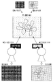
例えば、偏光素子を利用したシャッター方式の専用メガネを用いる3D画像表示システムや、偏光で出力した画像を偏光特性の異なる専用メガネを用いて複数の観賞者に振り分けて提示する同時マルチ画像表示システム(図14を参照。)に対しても有効である。 For example, a 3D image display system using shutter-type dedicated glasses using polarizing elements, or a simultaneous multi-image display system that distributes and presents images output by polarized light to a plurality of viewers using dedicated glasses with different polarization characteristics ( (See FIG. 14).
さらには、図13に示したような、ライドアトラクション等において、観賞者と連動して動く偏光板1301を広義のメガネとみなして本発明を適用することも可能である。
Furthermore, in the ride attraction as shown in FIG. 13, the present invention can be applied by regarding the
[実施例4]
実施例1及び2では、入力された画像データをメガネの傾きに応じた色補正を行う態様について説明した。次に、色補正の中でも、3D映像視聴の際の妨害要因となるクロストークを画像処理にて打ち消す態様について、実施例4として説明する。なお、実施例1及び2と共通する点については説明を省略し、ここでは差異点を中心に説明することとする。
[Example 4]
In the first and second embodiments, the aspect in which the input image data is subjected to color correction according to the inclination of the glasses has been described. Next, an aspect of canceling crosstalk, which is a disturbing factor when viewing 3D video, by image processing during color correction will be described as a fourth embodiment. In addition, description is abbreviate | omitted about the point which is common in Example 1 and 2, and suppose that it demonstrates centering on a difference point here.
まず、3D映像のクロストークについて説明する。 First, 3D video crosstalk will be described.
3D映像のクロストークとは、左眼に見せたい映像が右眼に漏れて見え、右眼に見せたい映像が左眼に漏れて見えてしまう現象である。そして、クロストークの色は、例えば偏光フィルムを用いた専用メガネ120の光学特性により変動し、さらに、鑑賞者の姿勢(視線方向を回転中心としたメガネの傾き)によっても変動する。
Crosstalk of 3D video is a phenomenon in which video that the user wants to show to the left eye appears to leak to the right eye, and video that the user wants to show to the right eye appears to leak to the left eye. The color of the crosstalk varies depending on the optical characteristics of the
図15は、クロストークを説明する図である。まず、左眼画像と右眼画像の2種類の画像からなる視差画像データを入力として、左眼画像には偏光A、右眼画像には偏光Bをかけて出力し、これらを同一画面上に表示する。鑑賞者は、左眼に偏光A、右眼に偏光Bの偏光フィルムの貼られた専用メガネ120を通してこの映像を鑑賞する。この結果、左眼には左眼画像のみが入り、右眼には右眼画像のみが入るのが理想であるが、実際には、反対側の眼に見せたい画像が互いにクロストークとして混入してしまう。図15には、このクロストークによって映像が2重像として見えてしまっている様子が示されている。
FIG. 15 is a diagram for explaining crosstalk. First, parallax image data consisting of two types of images, a left-eye image and a right-eye image, is input and output with polarization A applied to the left-eye image and polarization B applied to the right-eye image, and these are output on the same screen. indicate. The viewer views this image through the
次に、本実施例における色補正処理について説明する。本実施例における色補正処理では、クロストーク補正処理を行い、この結果色補正画像としてクロストーク補正画像を得る。なお、本実施例では、専用メガネ120越しに測定した表示デバイスの測色データに加えて、専用メガネ120越しに測定したクロストークの測色データをあらかじめ用意しておき、これらを用いてクロストーク補正処理を行う。
Next, color correction processing in the present embodiment will be described. In the color correction processing in this embodiment, crosstalk correction processing is performed, and as a result, a crosstalk correction image is obtained as a color correction image. In this embodiment, in addition to the color measurement data of the display device measured through the
(表示デバイスの測色について)
表示デバイスの測色データは、実施例1に係る図5のフローチャートのステップ501で説明した方法で得ることができる。具体的には、RGB色空間を格子状に分割して生成した各格子点に相当するRGB値を、画像出力装置である液晶ディスプレイ130に入力して表示し、その画像表示面を測色する。測色には例えば分光放射輝度計を用い、専用メガネ120を所定の観賞角度θに設定して、レンズ越しに測色する。そして、このような測色を実施例1と同様に任意の間隔・範囲の鑑賞角度θについて繰り返し行い、得られたXYZ値をL*a*b*値に変換して、変換後のL*a*b*値と格子点のRGB値とを対応付けた測色データF(L,θ)及びF(R,θ)を得る。F(L,θ)は左眼用のレンズL越しに測定された表示デバイスの測色データ、F(R,θ)は右眼用のレンズR越しに測定された表示デバイスの測色データである。ここで、F(L,θ)の測色は、左眼画像として格子点のRGB値を表示し、右眼画像は非表示とした状態で行う。逆に、F(R,θ)の測色は、右眼画像として格子点のRGB値を表示し、左眼画像は非表示とした状態で行う。図16の(a)及び(b)は、このようにして得られた表示デバイスの測色データF(L,θ)及びF(R,θ)の具体例をそれぞれ示している。得られた測色データは、HDD204に記憶される。
(About display device colorimetry)
The color measurement data of the display device can be obtained by the method described in step 501 of the flowchart of FIG. 5 according to the first embodiment. Specifically, an RGB value corresponding to each grid point generated by dividing the RGB color space into a grid is input and displayed on the
(クロストークの測色について)
基本的な測色の流れは、表示デバイスの測色と同様であるため詳細な説明は省略するが、クロストークの測色では、測色するレンズと表示する画像との対応関係が前述の表示デバイスの測色の時とは異なる。具体的には、左眼用のレンズL越しに測色を行う場合は、右眼用画像として格子点のRGB値を表示し、左眼画像は非表示とした状態で行う。逆に、右目用のレンズR越しに測色を行う場合は、左眼用画像として格子点のRGB値を表示し、右眼画像は非表示とした状態で行う。このようにすることで左右それぞれのクロストークを測色することができる。図17の(a)及び(b)は、左眼のクロストーク測色データG(L,θ)及び右眼のクロストーク測色データG(R,θ)の具体例をそれぞれ示している。得られた測色データは、HDD204に記憶される。
(About crosstalk colorimetry)
The basic colorimetric flow is the same as that for display devices, so a detailed description is omitted. However, in crosstalk colorimetry, the correspondence between the colorimetric lens and the displayed image is displayed as described above. It is different from the device colorimetry. Specifically, when performing color measurement through the lens L for the left eye, the RGB values of the grid points are displayed as the right eye image, and the left eye image is not displayed. Conversely, when color measurement is performed through the right-eye lens R, the RGB values of the grid points are displayed as the left-eye image, and the right-eye image is not displayed. By doing so, it is possible to measure the color of the left and right crosstalk. FIGS. 17A and 17B show specific examples of left-eye crosstalk colorimetric data G (L, θ) and right-eye crosstalk colorimetric data G (R, θ), respectively. The obtained color measurement data is stored in the
図18は、本実施例におけるクロストーク補正処理の流れを示すフローチャートである。なお、一部のステップは実施例1に係る図3のフローチャートにおける処理と同様であるため、これらについては詳細な説明は省略する。 FIG. 18 is a flowchart showing the flow of crosstalk correction processing in this embodiment. Since some steps are the same as the processing in the flowchart of FIG. 3 according to the first embodiment, detailed description thereof is omitted.
ステップ1601において、CPU201は、液晶ディスプレイ130に表示する画像データを取得する。例えば、入力I/F206を介してデジタルカメラ209から取得してもよいし、HDDI/F205を介してHDD204などの二次記憶装置に保存されている画像データを取得してもよい。取得(入力)される画像データは、左眼画像と右眼画像の2種類の画像からなる視差画像データである。
In step 1601, the
ステップ1602において、CPU201は、傾きセンサ121から専用メガネ120の傾き情報を取得する。処理の詳細は、図3のフローチャートにおけるステップ302と同様であるため説明を省略する。
In step 1602, the
ステップ1603において、CPU201は、ステップ1602で取得した傾き情報に基づき、左右それぞれの眼に対応するクロストーク測色データを取得する。具体的には、取得した傾き情報が示す角度θに対応する左眼のクロストーク測色データG(L,θ)と右眼のクロストーク測色データG(R,θ)を、HDD204から取得する。なお、クロストーク測色データが、例えば5度刻みで作成されていた場合には、取得した傾き情報(角度θ)に対応するクロストーク測色データが存在しないということも十分考えられる。この場合は、θ0<θ<θ1を満たすような2つの角度(θ0とθ1)に対応する2つのクロストーク測色データを用いて補間処理を行い、取得された傾き情報に対応するクロストーク測色データを導出する。また、角度θ0とθ1に対応するクロストーク測色データが存在しない場合は、取得された傾き情報(角度θ)に最も近い角度のクロストーク測色データを選択して、使用するクロストーク測色データとして決定する。なお、クロストーク測色データを予め用意する際、角度の範囲や間隔は特定の条件に限定されるものではなく、実施例1の色補正パラメータと同様の方法で設定すればよい。
In
ステップ1604において、CPU201は、参照画像の画素値とクロストーク測色データから、左右それぞれの眼に対応するクロストーク補正パラメータを導出する。ここで、参照画像とは、処理対象の眼とは反対の眼に表示したい画像をいう。具体的には、左目用のクロストーク補正パラメータを導出する際は右眼画像を参照画像とし、右目用のクロストーク補正パラメータを導出する際は左眼画像を参照画像とする。本ステップで得られるクロストーク補正パラメータは、参照画像の各画素のRGB値に対応するクロストークのL*a*b*値となる。具体的には、左眼用のクロストーク補正パラメータH(L)を導出する場合は、右眼画像を参照画像とし、参照画像の各画素のRGB値でクロストーク測色データG(L,θ)を参照することにより求めることができる。右眼用のクロストーク補正パラメータH(R)はこの逆の方法、すなわち、左眼画像を参照画像とし、参照画像の各画素のRGB値でクロストーク測色データG(R,θ)を参照することにより求めることができる。なお、参照画像内にクロストーク測色データに対応していない(すなわち、格子点と一致しない)RGB値がある場合には、その近傍格子点から四面体補間等の補間処理を行って、クロストーク補正パラメータを求めればよい。
In step 1604, the
ステップ1605において、CPU201は、ステップ1604で導出されたクロストーク補正パラメータを用いて、ステップ1601で入力された視差画像データの画素値を補正し、クロストーク補正画像データ(色補正画像データ)を生成する。入力される視差画像データと同様、クロストーク補正画像データも左眼クロストーク補正画像と右眼クロストーク補正画像とで構成される。以下、左眼クロストーク補正画像の生成を例に、視差画像データの画素値をどのように補正するのかを具体的に説明する。
In
まず、ステップ1601で取得した入力画像である左眼画像のRGB値で左眼用のレンズL越しに測定された表示デバイスの測色データF(L,θ)を参照して、左眼画像のL*a*b*値を求める。なお、左眼画像内に測色データに対応していない(すなわち、格子点と一致しない)RGB値がある場合には、その近傍格子点から四面体補間等の補間処理を行って、対象となっているRGB値に対応したL*a*b*値を求めればよい。 First, referring to the colorimetric data F (L, θ) of the display device measured through the left-eye lens L with the RGB value of the left-eye image that is the input image acquired in step 1601, the left-eye image Find the L * a * b * value. If there is an RGB value in the left eye image that does not correspond to the colorimetric data (that is, does not match the grid point), an interpolation process such as tetrahedral interpolation is performed from the neighboring grid point, and the target What is necessary is just to obtain the L * a * b * value corresponding to the RGB value.
次に、得られた左眼画像のL*a*b*値から、ステップ1604で導出したクロストーク補正パラメータH(L)を減算し、左眼クロストーク補正画像のL*a*b*値を求める。 Next, the L * a * b * value of the left eye crosstalk correction image is subtracted from the L * a * b * value of the obtained left eye image by subtracting the crosstalk correction parameter H (L) derived in step 1604. Ask for.
最後に、左眼用のレンズL越しに測定された表示デバイスの測色データF(L,θ)に基づき、左眼クロストーク補正画像のL*a*b*値をRGB値へ逆変換して、左眼クロストーク補正画像のRGB値を求める。なお、変換後のRGB値がマイナスの値や256以上の値をとる場合は、適切にクリッピング処理を行えばよい。同様の方法で、右眼クロストーク補正画像も生成される。 Finally, based on the colorimetric data F (L, θ) of the display device measured through the lens L for the left eye, the L * a * b * value of the left eye crosstalk correction image is converted back to an RGB value. Thus, the RGB value of the left-eye crosstalk correction image is obtained. When the converted RGB value takes a negative value or a value of 256 or more, the clipping process may be performed appropriately. A right eye crosstalk correction image is also generated in the same manner.
ステップ1606において、CPU201は、生成されたクロストーク補正画像データを液晶ディスプレイ130へ送る。そして、液晶ディスプレイ130において、クロストーク補正画像データが表示される。
In
以上のような色補正処理により、メガネの傾きに応じてクロストークの補正がなされるので、観賞姿勢に依存したクロストークの発生を抑制することが可能となる。 By the color correction process as described above, the crosstalk is corrected according to the inclination of the glasses, so that the occurrence of crosstalk depending on the viewing posture can be suppressed.
本実施例では、クロストーク補正画像のRGB値がマイナスの値をとる場合にクリッピング処理をすればよいとしたが、この処理により色転び等の弊害が生じる可能性がある。そこで、予め、例えばクロストークの値に応じて導出したオフセット量で入力画像の画素値をオフセットしておくことが考えられる。これにより、補正後にRGB値がマイナスの値となるのを防ぐことができ、色転びを生じさせることなくクロストークをより抑制することができる。この場合のオフセット量は、メガネの傾きに応じて適宜変更すればよい。さらに、オフセット量を導出する際のクロストークの値は、例えばクロストーク測色データ内の最大値とする。もちろん、このオフセット量を入力画像ごとに適宜変更するようにしてもよいことは言うまでもない。 In this embodiment, the clipping process may be performed when the RGB value of the crosstalk correction image takes a negative value. However, this process may cause a problem such as a color shift. Thus, it is conceivable to offset the pixel value of the input image in advance with an offset amount derived according to the value of crosstalk, for example. As a result, the RGB value can be prevented from becoming a negative value after correction, and crosstalk can be further suppressed without causing color shift. The offset amount in this case may be appropriately changed according to the inclination of the glasses. Furthermore, the value of crosstalk when deriving the offset amount is, for example, the maximum value in the crosstalk colorimetric data. Of course, it goes without saying that this offset amount may be appropriately changed for each input image.
また、本実施例で説明したクロストーク補正処理によって生成されたクロストーク補正画像データが、新たなクロストークを発生してしまうことが考えられる。これに対しては、生成されたクロストーク補正画像データを新たに入力画像データとして、左右の眼に対応するクロストーク補正画像データを順次更新していくことで抑制することができる。なお、クロストーク補正画像データの更新の繰り返し回数は、例えばクロストークの許容値をあらかじめ定めておき、クロストーク補正パラメータがこれを下回るまで行うといった具合に設定すればよい。 Further, it is conceivable that the crosstalk correction image data generated by the crosstalk correction processing described in the present embodiment generates new crosstalk. This can be suppressed by sequentially updating the crosstalk correction image data corresponding to the left and right eyes using the generated crosstalk correction image data as new input image data. Note that the number of repetitions of updating the crosstalk correction image data may be set such that, for example, an allowable value of crosstalk is determined in advance and the crosstalk correction parameter is lowered below this value.
さらに、実施例1や2で説明した色補正処理と本実施例で説明したクロストーク補正処理とを同時に実施するようにしてもよい。すなわち、F(L,θ)の代わりにF'(L,θ)やF''(L,θ)を用いて本実施例で説明したクロストーク補正処理を行うようにしてもよい。 Furthermore, the color correction processing described in the first and second embodiments and the crosstalk correction processing described in the present embodiment may be performed simultaneously. That is, the crosstalk correction processing described in the present embodiment may be performed using F ′ (L, θ) or F ″ (L, θ) instead of F (L, θ).
[実施例5]
実施例4では、あらかじめ様々な回転角度に対してクロストークを測色しておき、得られた測色データを用いてメガネの傾きに応じてクロストークの補正を行う態様について説明した。次に、例えば最もクロストークの強く発生する回転角度のみクロストークを測色しておき、これ以外の角度に対しては、補間計算にてクロストークの色を導出する態様について実施例5として説明する。なお、実施例4と共通する点については説明を省略し、ここでは差異点を中心に説明することとする。
[Example 5]
In the fourth embodiment, a mode has been described in which crosstalk is measured in advance for various rotation angles, and crosstalk correction is performed according to the inclination of the glasses using the obtained colorimetric data. Next, for example, an embodiment in which the crosstalk color is measured only at the rotation angle at which the strongest crosstalk occurs and the crosstalk color is derived by interpolation calculation for other angles will be described as a fifth embodiment. To do. In addition, description is abbreviate | omitted about the point which is common in Example 4, and suppose that it demonstrates centering on a difference point here.
まず、本実施例におけるクロストークの測色について説明する。 First, crosstalk colorimetry in the present embodiment will be described.
本実施例では、クロストークが最も強く発生する専用メガネ120の回転角度に対してのみクロストークの測色を行う。クロストークが最も強く発生する回転角度は専用メガネ120の偏光フィルムの光学特性等により異なるが、ここでは、回転角度が90度の場合にクロストークが最も強く発生するものとする。この場合、専用メガネ120を90度まわした状態に固定して、実施例4と同様の方法でクロストークの測色を行うことになる。これにより、左眼のクロストーク測色データG(L,90度)及び右眼のクロストーク測色データG(R,90度)を得る。
In the present embodiment, the color measurement of the crosstalk is performed only for the rotation angle of the
次に、専用メガネ120の傾き情報に応じたクロストーク測色データの導出方法について説明する。本実施例では、専用メガネ120の光学特性を基に、クロストークの輝度の変化量をSinの絶対値に近似し、これを回転角度に応じたクロストーク補正係数W(θ)とする。図19は、クロストーク補正係数のグラフを示している。なお、本実施例では、クロストークの輝度の変化量をSinの絶対値に近似しているが、専用メガネの光学特性に応じてこの近似関数は適切に定義する必要がある。そして、このクロストーク補正係数W(θ)をクロストーク測色データG(L,90度)、G(R,90度)に掛けることにより、目的の回転角度に対応するクロストーク測色データを導出することができる。
Next, a method for deriving crosstalk colorimetric data corresponding to the tilt information of the
このようにして求めたクロストーク測色データを用いて、実施例4で説明したクロストーク補正処理を行うことにより、クロストーク測色にかかる工数を削減しつつ観賞姿勢に依存したクロストークの発生を抑制することが可能となる。 By performing the crosstalk correction processing described in the fourth embodiment using the crosstalk colorimetric data thus obtained, the occurrence of crosstalk depending on the viewing posture while reducing the man-hours required for crosstalk colorimetry. Can be suppressed.
(その他の実施形態)
また、本発明の目的は、以下の処理を実行することによっても達成される。即ち、上述した実施形態の機能を実現するソフトウェアのプログラムコードを記録した記憶媒体を、システム或いは装置に供給し、そのシステム或いは装置のコンピュータ(またはCPUやMPU等)が記憶媒体に格納されたプログラムコードを読み出す処理である。この場合、記憶媒体から読み出されたプログラムコード自体が前述した実施の形態の機能を実現することになり、そのプログラムコード及び該プログラムコードを記憶した記憶媒体は本発明を構成することになる。
(Other embodiments)
The object of the present invention can also be achieved by executing the following processing. That is, a storage medium that records a program code of software that realizes the functions of the above-described embodiments is supplied to a system or apparatus, and a computer (or CPU, MPU, etc.) of the system or apparatus is stored in the storage medium. This is the process of reading the code. In this case, the program code itself read from the storage medium realizes the functions of the above-described embodiments, and the program code and the storage medium storing the program code constitute the present invention.
Claims (24)
前記画像表示装置の表示面に対する前記メガネの傾き情報に基づき、表示される画像を示す画像データに対する色補正処理を行う色補正手段と、
を備え、
前記色補正手段は、複数の回転角度に対応付けられた複数の色補正パラメータの中から、前記メガネの傾き情報に基づいて、前記色補正処理に用いる色補正パラメータを取得する
ことを特徴とする画像処理装置。 An image processing apparatus for an image display system including glasses having a polarizing element and an image display apparatus,
Color correction means for performing color correction processing on image data indicating an image to be displayed based on inclination information of the glasses with respect to the display surface of the image display device ;
With
The color correction unit acquires a color correction parameter used for the color correction process based on tilt information of the glasses from a plurality of color correction parameters associated with a plurality of rotation angles. Image processing device.
前記画像表示装置の表示面に対する前記メガネの傾き情報に基づき、表示される画像を示す画像データに対する色補正処理を行う色補正ステップと、
を含み、
前記色補正ステップでは、複数の回転角度に対応付けられた複数の色補正パラメータの中から、前記メガネの傾き情報に基づいて、前記色補正処理に用いる色補正パラメータを取得する
ことを特徴とする画像処理方法。 An image processing method for an image display system including glasses having a polarizing element and an image display device,
A color correction step for performing color correction processing on image data indicating an image to be displayed based on tilt information of the glasses with respect to the display surface of the image display device ;
Including
In the color correction step, from among a plurality of color correction parameters associated with a plurality of rotation angles, a color correction parameter used for the color correction process is acquired based on tilt information of the glasses. Image processing method.
前記画像表示装置の表示面に対する前記メガネの傾き情報および参照画像の画素値に基づき、表示される画像を示す画像データに対する色補正処理を行う色補正手段を備える
ことを特徴とする画像処理装置。 An image processing apparatus for an image display system including glasses having a polarizing element and an image display apparatus,
An image processing apparatus comprising color correction means for performing color correction processing on image data indicating an image to be displayed based on tilt information of the glasses with respect to a display surface of the image display apparatus and a pixel value of a reference image.
前記メガネを回転した際の輝度の変化量からクロストークの補正係数を導出する手段と、
前記クロストーク測色手段により得られるクロストーク測色データと前記クロストークの補正係数から、特定の回転角度に対応するクロストークの測色データを導出する手段と
をさらに備えることを特徴とする請求項13に記載の画像処理装置。 Crosstalk colorimetry means for measuring crosstalk only for the inclination of the glasses where crosstalk occurs most,
Means for deriving a correction coefficient for crosstalk from the amount of change in luminance when the glasses are rotated;
A means for deriving crosstalk colorimetric data corresponding to a specific rotation angle from the crosstalk colorimetric data obtained by the crosstalk colorimetric means and the crosstalk correction coefficient. Item 14. The image processing apparatus according to Item 13 .
前記画像表示装置の表示面に対する前記メガネの傾き情報および参照画像の画素値に基づき、表示される画像を示す画像データに対する色補正処理を行う色補正ステップを含む ことを特徴とする画像処理方法。 An image processing method for an image display system including glasses having a polarizing element and an image display device,
An image processing method comprising: a color correction step of performing color correction processing on image data indicating an image to be displayed based on tilt information of the glasses with respect to a display surface of the image display device and a pixel value of a reference image.
Priority Applications (2)
| Application Number | Priority Date | Filing Date | Title |
|---|---|---|---|
| JP2013076145A JP6202856B2 (en) | 2012-06-21 | 2013-04-01 | Image processing apparatus, image processing method, and program |
| US13/918,474 US20130342662A1 (en) | 2012-06-21 | 2013-06-14 | Image processing device, image processing method, and program |
Applications Claiming Priority (3)
| Application Number | Priority Date | Filing Date | Title |
|---|---|---|---|
| JP2012139989 | 2012-06-21 | ||
| JP2012139989 | 2012-06-21 | ||
| JP2013076145A JP6202856B2 (en) | 2012-06-21 | 2013-04-01 | Image processing apparatus, image processing method, and program |
Publications (3)
| Publication Number | Publication Date |
|---|---|
| JP2014027647A JP2014027647A (en) | 2014-02-06 |
| JP2014027647A5 JP2014027647A5 (en) | 2016-04-07 |
| JP6202856B2 true JP6202856B2 (en) | 2017-09-27 |
Family
ID=49774117
Family Applications (1)
| Application Number | Title | Priority Date | Filing Date |
|---|---|---|---|
| JP2013076145A Active JP6202856B2 (en) | 2012-06-21 | 2013-04-01 | Image processing apparatus, image processing method, and program |
Country Status (2)
| Country | Link |
|---|---|
| US (1) | US20130342662A1 (en) |
| JP (1) | JP6202856B2 (en) |
Families Citing this family (3)
| Publication number | Priority date | Publication date | Assignee | Title |
|---|---|---|---|---|
| EP3185550A1 (en) * | 2015-12-23 | 2017-06-28 | Thomson Licensing | Tridimensional rendering with adjustable disparity direction |
| JP2017127396A (en) * | 2016-01-18 | 2017-07-27 | キヤノン株式会社 | Display system, eye-mounting fixture and method for controlling display system |
| CN112598594A (en) * | 2020-12-24 | 2021-04-02 | Oppo(重庆)智能科技有限公司 | Color consistency correction method and related device |
Family Cites Families (18)
| Publication number | Priority date | Publication date | Assignee | Title |
|---|---|---|---|---|
| JP3614126B2 (en) * | 2001-10-18 | 2005-01-26 | ミノルタ株式会社 | Digital camera |
| GB2390948A (en) * | 2002-07-17 | 2004-01-21 | Sharp Kk | Autostereoscopic display |
| JP2006113088A (en) * | 2004-10-12 | 2006-04-27 | Matsushita Electric Ind Co Ltd | Crosstalk dissolving polarizing 3d system |
| EP2501139A3 (en) * | 2005-05-26 | 2014-01-08 | RealD Inc. | Ghost-compensation for improved stereoscopic projection |
| JP2009128381A (en) * | 2007-11-19 | 2009-06-11 | Sharp Corp | Liquid crystal display, display system, color correction method, program and recording medium thereof |
| US20100110069A1 (en) * | 2008-10-31 | 2010-05-06 | Sharp Laboratories Of America, Inc. | System for rendering virtual see-through scenes |
| US8436918B2 (en) * | 2009-02-27 | 2013-05-07 | Deluxe Laboratories, Inc. | Systems, apparatus and methods for subtitling for stereoscopic content |
| JP5266126B2 (en) * | 2009-03-31 | 2013-08-21 | 富士フイルム株式会社 | Image display apparatus and method, and program |
| KR101636537B1 (en) * | 2009-11-12 | 2016-07-06 | 삼성전자주식회사 | Image processing apparatus and method for enhancing of depth perception |
| JP5641318B2 (en) * | 2009-11-18 | 2014-12-17 | パナソニックIpマネジメント株式会社 | Video signal processing device, video display device, video signal processing method, and integrated circuit |
| US8399267B2 (en) * | 2009-12-26 | 2013-03-19 | Achrolux Inc | Methods for packaging light emitting devices and related microelectronic devices |
| US8384774B2 (en) * | 2010-02-15 | 2013-02-26 | Eastman Kodak Company | Glasses for viewing stereo images |
| WO2012023922A1 (en) * | 2010-08-19 | 2012-02-23 | Thomson Licensing | Color calibration and compensation for 3d display systems |
| JP2012042883A (en) * | 2010-08-23 | 2012-03-01 | Canon Inc | Image processing system and method |
| JP4804586B1 (en) * | 2010-09-21 | 2011-11-02 | 稔 稲葉 | 3D image display device and 3D image viewing glasses |
| JP5612424B2 (en) * | 2010-10-01 | 2014-10-22 | 株式会社ジャパンディスプレイ | Stereoscopic image display device |
| TWI441093B (en) * | 2010-10-29 | 2014-06-11 | Altek Corp | Method for generating three dimensional image and three dimensional imaging system |
| US20120113235A1 (en) * | 2010-11-08 | 2012-05-10 | Sony Corporation | 3d glasses, systems, and methods for optimized viewing of 3d video content |
-
2013
- 2013-04-01 JP JP2013076145A patent/JP6202856B2/en active Active
- 2013-06-14 US US13/918,474 patent/US20130342662A1/en not_active Abandoned
Also Published As
| Publication number | Publication date |
|---|---|
| JP2014027647A (en) | 2014-02-06 |
| US20130342662A1 (en) | 2013-12-26 |
Similar Documents
| Publication | Publication Date | Title |
|---|---|---|
| KR101870865B1 (en) | Apparatus and method for 3d augmented information video see-through display, rectification apparatus | |
| US9021399B2 (en) | Stereoscopic image reproduction device and method for providing 3D user interface | |
| TWI598846B (en) | Image data processing method and stereoscopic image display using the same | |
| US8208048B2 (en) | Method for high dynamic range imaging | |
| US8514219B2 (en) | 3D image special effects apparatus and a method for creating 3D image special effects | |
| US20130241947A1 (en) | Display device, image processing device, image processing method, and computer program | |
| JP5831024B2 (en) | Image processing apparatus, image processing method, and program | |
| JP6114742B2 (en) | Position indicator for 3D display | |
| WO2012037685A1 (en) | Generating 3d stereoscopic content from monoscopic video content | |
| KR20060063575A (en) | Apparatus and method for correction of the image distortion of stereo-camera | |
| US20120044241A1 (en) | Three-dimensional on-screen display imaging system and method | |
| US9307227B2 (en) | Stereoscopic image registration and color balance evaluation display | |
| JP6202856B2 (en) | Image processing apparatus, image processing method, and program | |
| KR101548236B1 (en) | Color compansation method for 3D Image | |
| JP2004336781A (en) | Color gamut indication | |
| KR20200051731A (en) | Lighting methods and systems that enhance perspective color perception of images observed by users | |
| US20180268751A1 (en) | Head-mounted display and chroma aberration compensation method using sub-pixel shifting | |
| JP2013104937A (en) | Display processing device and display processing method | |
| KR20140029123A (en) | 3 dimension image diisplay apparatus having a color compensation function and color compensation method using the same | |
| JP5928280B2 (en) | Multi-viewpoint image generation apparatus and method | |
| TWI547142B (en) | Guided 3d display adaptation | |
| JP2015125493A (en) | Image generation method, image generation device, and image generation program | |
| Gunnewiek et al. | How to display 3D content realistically | |
| WO2012063540A1 (en) | Virtual viewpoint image generating device | |
| JP2012042883A (en) | Image processing system and method |
Legal Events
| Date | Code | Title | Description |
|---|---|---|---|
| A521 | Request for written amendment filed |
Free format text: JAPANESE INTERMEDIATE CODE: A523 Effective date: 20160223 |
|
| A621 | Written request for application examination |
Free format text: JAPANESE INTERMEDIATE CODE: A621 Effective date: 20160223 |
|
| A977 | Report on retrieval |
Free format text: JAPANESE INTERMEDIATE CODE: A971007 Effective date: 20161226 |
|
| A131 | Notification of reasons for refusal |
Free format text: JAPANESE INTERMEDIATE CODE: A131 Effective date: 20170110 |
|
| A521 | Request for written amendment filed |
Free format text: JAPANESE INTERMEDIATE CODE: A523 Effective date: 20170224 |
|
| TRDD | Decision of grant or rejection written | ||
| A01 | Written decision to grant a patent or to grant a registration (utility model) |
Free format text: JAPANESE INTERMEDIATE CODE: A01 Effective date: 20170801 |
|
| A61 | First payment of annual fees (during grant procedure) |
Free format text: JAPANESE INTERMEDIATE CODE: A61 Effective date: 20170829 |
|
| R151 | Written notification of patent or utility model registration |
Ref document number: 6202856 Country of ref document: JP Free format text: JAPANESE INTERMEDIATE CODE: R151 |