JP6202497B2 - Radiation sterilization of implantable medical devices - Google Patents
Radiation sterilization of implantable medical devices Download PDFInfo
- Publication number
- JP6202497B2 JP6202497B2 JP2013502660A JP2013502660A JP6202497B2 JP 6202497 B2 JP6202497 B2 JP 6202497B2 JP 2013502660 A JP2013502660 A JP 2013502660A JP 2013502660 A JP2013502660 A JP 2013502660A JP 6202497 B2 JP6202497 B2 JP 6202497B2
- Authority
- JP
- Japan
- Prior art keywords
- dose
- medical device
- dose level
- level
- radiation
- Prior art date
- Legal status (The legal status is an assumption and is not a legal conclusion. Google has not performed a legal analysis and makes no representation as to the accuracy of the status listed.)
- Expired - Fee Related
Links
Images


Classifications
-
- A—HUMAN NECESSITIES
- A61—MEDICAL OR VETERINARY SCIENCE; HYGIENE
- A61L—METHODS OR APPARATUS FOR STERILISING MATERIALS OR OBJECTS IN GENERAL; DISINFECTION, STERILISATION OR DEODORISATION OF AIR; CHEMICAL ASPECTS OF BANDAGES, DRESSINGS, ABSORBENT PADS OR SURGICAL ARTICLES; MATERIALS FOR BANDAGES, DRESSINGS, ABSORBENT PADS OR SURGICAL ARTICLES
- A61L2/00—Methods or apparatus for disinfecting or sterilising materials or objects other than foodstuffs or contact lenses; Accessories therefor
- A61L2/02—Methods or apparatus for disinfecting or sterilising materials or objects other than foodstuffs or contact lenses; Accessories therefor using physical phenomena
- A61L2/08—Radiation
- A61L2/087—Particle radiation, e.g. electron-beam, alpha or beta radiation
-
- A—HUMAN NECESSITIES
- A61—MEDICAL OR VETERINARY SCIENCE; HYGIENE
- A61L—METHODS OR APPARATUS FOR STERILISING MATERIALS OR OBJECTS IN GENERAL; DISINFECTION, STERILISATION OR DEODORISATION OF AIR; CHEMICAL ASPECTS OF BANDAGES, DRESSINGS, ABSORBENT PADS OR SURGICAL ARTICLES; MATERIALS FOR BANDAGES, DRESSINGS, ABSORBENT PADS OR SURGICAL ARTICLES
- A61L2/00—Methods or apparatus for disinfecting or sterilising materials or objects other than foodstuffs or contact lenses; Accessories therefor
- A61L2/02—Methods or apparatus for disinfecting or sterilising materials or objects other than foodstuffs or contact lenses; Accessories therefor using physical phenomena
- A61L2/08—Radiation
-
- A—HUMAN NECESSITIES
- A61—MEDICAL OR VETERINARY SCIENCE; HYGIENE
- A61L—METHODS OR APPARATUS FOR STERILISING MATERIALS OR OBJECTS IN GENERAL; DISINFECTION, STERILISATION OR DEODORISATION OF AIR; CHEMICAL ASPECTS OF BANDAGES, DRESSINGS, ABSORBENT PADS OR SURGICAL ARTICLES; MATERIALS FOR BANDAGES, DRESSINGS, ABSORBENT PADS OR SURGICAL ARTICLES
- A61L2/00—Methods or apparatus for disinfecting or sterilising materials or objects other than foodstuffs or contact lenses; Accessories therefor
- A61L2/24—Apparatus using programmed or automatic operation
Description
[0001]本発明は医療デバイスに関する。より詳細には、本発明は、医療デバイスの照射によって医療デバイスを滅菌する方法に関する。 [0001] The present invention relates to medical devices. More particularly, the present invention relates to a method for sterilizing a medical device by irradiation of the medical device.
[0002]有害な微生物を除去するために、食品又は郵便物などの製品を滅菌するためのシステムが、当技術分野で知られている。そのようなシステムは、製品があらかじめ定められたレベル又は強度で、例えばX線、ガンマ又は電子放射線などのあらかじめ定められた線量の放射線にさらされる放射線源を通って運ばれるコンベヤとして動作することができる。製品に照射される線量を注意深く継続的に制御することが重要である。製品が受け取る放射線が少なすぎると、所望される滅菌、殺菌及び化学修飾のうち1つ以上は得られない。製品が受け取る放射線が多すぎると、処理によって製品が損傷する。 [0002] Systems for sterilizing products such as food or mail to remove harmful microorganisms are known in the art. Such a system may operate as a conveyor where products are carried at a predetermined level or intensity through a radiation source exposed to a predetermined dose of radiation, such as X-rays, gamma or electronic radiation. it can. It is important to carefully and continuously control the dose delivered to the product. If the product receives too little radiation, one or more of the desired sterilization, sterilization and chemical modification cannot be obtained. If the product receives too much radiation, the product will be damaged by the process.
[0003]十分な滅菌を確実にするために、製品を放射線源の前の2つのパスに曝露し、又は放射線場の中で製品を回転させることが知られている。米国特許第6806476号は、コンベヤの上の製品を放射線源の前の2つのパス、例えば電子ビームに通すように操作される放射線コンベヤシステムを開示している。製品は第1のパスと第2のパスとの間で180度反転される。システムは製品を、特に、線量レベル、ビーム幅、選択されたコンベヤの速度及び電子エネルギー拡散スペクトルによって定義された、あらかじめ定められたレベルの放射線に曝露する。 [0003] It is known to expose the product to two passes in front of the radiation source or to rotate the product in a radiation field to ensure sufficient sterilization. U.S. Pat. No. 6,806,476 discloses a radiation conveyor system that is operated to pass the product on the conveyor through two passes in front of the radiation source, e.g. an electron beam. The product is inverted 180 degrees between the first pass and the second pass. The system exposes the product to a predetermined level of radiation, defined in particular by dose level, beam width, selected conveyor speed and electron energy diffusion spectrum.
[0004]特に密度の高い製品では、当技術分野では、米国特許第6806476号に説明されているように、放射線源の前の2つのパスを実施するように、システムが構成される。第1のパスは、製品を放射線源の前の幅広い辺に配置することができる。次いで、製品は180度反転され、再度放射線源の前の幅広い辺を通過する。これにより、最小限の線量レベルを製品に照射して、確実な滅菌を行う。両方のパスには、同じ線量レベルが使用される。 [0004] For particularly dense products, the art is configured in the art to perform the two previous passes of the radiation source, as described in US Pat. No. 6,806,476. The first pass can place the product on a wide side in front of the radiation source. The product is then inverted 180 degrees and again passes through the wide side in front of the radiation source. This ensures that the product is exposed to a minimum dose level and is sterilized reliably. The same dose level is used for both passes.
[0005]放射線への曝露による埋め込み式医療デバイスの滅菌は既知である。滅菌は一般に、デバイスのバイオバーデンを減らすように、ステント及びカテーテルなどの埋め込み式医療デバイスに実施される。バイオバーデンとは、一般に対象物に混入している微生物の数のことをいう。滅菌の程度は、一般に、滅菌後に生存する微生物が存在する確率をデバイス単位で示す無菌性保証レベル(「SAL」)によって測定される。滅菌線量は、必要な「SAL」をもたらす線量を選択することによって、決定することができる。デバイスに必要なSALは、デバイスの使用目的によって決まる。例えば、体内の流路で使用されるデバイスは、クラスIIIデバイスとみなされる。様々な医療デバイスのためのSALは、バージニア州アーリントンの医療器具開発協会(Association for the Advancement of Medical Instrumentation(AAMI))による資料で確認することができる。例えば、生分解性ステントのためのSALは、約20kGy〜約30kGyの放射線線量である。必要な線量は、医療デバイスが作製されるときに維持される滅菌の程度によって異なり得る、医療デバイスにおける最初のバイオバーデンに依存する。 [0005] Sterilization of implantable medical devices by exposure to radiation is known. Sterilization is typically performed on implantable medical devices such as stents and catheters to reduce the bioburden of the device. Bioburden generally refers to the number of microorganisms mixed in an object. The degree of sterilization is generally measured by the level of sterility assurance (“SAL”), which indicates the probability of the presence of microorganisms that survive after sterilization on a device-by-device basis. The sterilization dose can be determined by selecting the dose that results in the required “SAL”. The SAL required for the device depends on the purpose of use of the device. For example, a device used in a body flow path is considered a class III device. SALs for various medical devices can be found in materials from the Association for the Advancement of Medical Instrumentation (AAMI), Arlington, Virginia. For example, a SAL for a biodegradable stent is a radiation dose of about 20 kGy to about 30 kGy. The required dose depends on the initial bioburden in the medical device, which can vary depending on the degree of sterilization maintained when the medical device is made.
[0006]全体又は一部がポリマーで構成された医療デバイスは、電子ビーム(e−ビーム)、ガンマ線、紫外線、赤外線、イオンビーム、及びX線滅菌を含むがこれに限定されない、様々な種類の放射線で滅菌することができる。滅菌線量は、必要なSALをもたらす線量を選択することによって決定することができる。当技術分野で有する1つの問題は、生体吸収性ポリマーとポリマーコーティング内に含まれる治療薬の両方又は一方に、劣化を生じることなくSALを達成するために十分な放射線を照射する方法である。高エネルギー放射線は、ポリマー分子のイオン化及び励起、並びにフリーラジカルを生じる傾向がある。これらのエネルギーの高い種は、電離、抽出、鎖切断及び架橋結合を順に経験し、化学安定性をもたらす。安定化のプロセスは、照射中、照射直後、若しくは照射の数日後、数週間後、又は数ヵ月後にさえ起きることがあり、結果として物理的及び化学的な架橋結合又は鎖切断を起こすことが多い。結果としての物理的変化には、とりわけ、苦味、変色、臭いの発生、硬化、及び軟化を含むことがある。特に、e−ビーム放射線滅菌による高分子材料及び薬剤の性能の低下は、放射線曝露中、及びポリマー鎖の他の部分との反応による、デバイスにおけるフリーラジカルの形成と関連付けられてきた。反応は、例えばe−ビーム線量及び温度レベルに依存する。 [0006] Medical devices composed entirely or in part of polymers are of various types, including but not limited to electron beams (e-beams), gamma rays, ultraviolet rays, infrared rays, ion beams, and x-ray sterilization. Sterilize with radiation. The sterilization dose can be determined by selecting the dose that results in the required SAL. One problem with the art is how to irradiate bioabsorbable polymers and / or therapeutic agents contained within the polymer coating with sufficient radiation to achieve SAL without causing degradation. High energy radiation tends to produce ionization and excitation of polymer molecules and free radicals. These high energy species in turn undergo ionization, extraction, chain scission and cross-linking, resulting in chemical stability. The stabilization process can occur during irradiation, immediately after irradiation, or days, weeks, or even months after irradiation, often resulting in physical and chemical cross-linking or strand breaks. . The resulting physical changes may include, among other things, bitterness, discoloration, odor development, curing, and softening. In particular, the loss of performance of polymeric materials and drugs due to e-beam radiation sterilization has been associated with the formation of free radicals in the device during radiation exposure and by reaction with other parts of the polymer chain. The response depends, for example, on the e-beam dose and the temperature level.
[0007]これらの理由により、ポリマーと放射線感受性の薬剤の両方又は一方を含む医療デバイスの滅菌手順は、医療デバイスが製品の性能を低下させることなく許容可能な線量レベルの上限を指定している。医療デバイスが劣化しないことを確実にする実際の上限として、又は滅菌が近似であることを確実にする実際の下限として、下限の線量範囲及び上限の線量範囲は安全因子を含む場合が多く、滅菌のための動作範囲を狭くしている。これにより、滅菌プロセスが複雑化し、医療デバイスに利用可能な設計又は材料の範囲が制限されている。 [0007] For these reasons, medical device sterilization procedures that include polymers and / or radiation sensitive agents specify an upper limit on the dose level that the medical device can tolerate without degrading product performance. . As the actual upper limit to ensure that the medical device does not degrade, or as the actual lower limit to ensure that sterilization is approximate, the lower dose range and the upper dose range often include safety factors and are sterilized. The operating range for is narrow. This complicates the sterilization process and limits the range of designs or materials available for medical devices.
[0008]したがって、放射線の過剰曝露によって悪影響を受けるポリマーと治療薬の両方又は一方を含む医療デバイスの滅菌のプロセスを、依然として改善する必要がある。 [0008] Accordingly, there remains a need to improve the process of sterilization of medical devices containing polymers and / or therapeutic agents that are adversely affected by overexposure to radiation.
[0009]本発明は、全体又は一部がポリマー材料で構成された医療デバイス及び放射線感受性の治療薬を含む医療デバイスの放射線滅菌のための方法及びシステムを提供する。好ましくは、e−ビーム滅菌が使用されるが、本発明の範囲から逸脱することなく、他の放射線滅菌源を使用することもできる。 [0009] The present invention provides a method and system for radiation sterilization of a medical device comprising a medical device composed entirely or in part of a polymeric material and a radiation sensitive therapeutic agent. Preferably, e-beam sterilization is used, but other radiation sterilization sources can be used without departing from the scope of the present invention.
[0010]本明細書で説明される方法及びシステムは特に、埋め込み式医療デバイスの滅菌プロセスを改善するように構成される。方法及びシステムは、特に、ポリマー基材、ポリマー性コーティング及び薬物送達コーティングの少なくとも1つを有する埋め込み式医療デバイスに関する。ポリマー性コーティングは、例えば、疾患部位に局所的に投与するための活性剤又は薬物を含むことができる。埋め込み式医療デバイスは、ポリマー性コーティングを有するポリマー又は非ポリマー基材を含むことができる。 [0010] The methods and systems described herein are specifically configured to improve the sterilization process of implantable medical devices. The methods and systems relate specifically to implantable medical devices having at least one of a polymer substrate, a polymeric coating, and a drug delivery coating. The polymeric coating can include, for example, an active agent or drug for local administration to the disease site. The implantable medical device can include a polymer or non-polymer substrate having a polymeric coating.
[0011]本発明による放射線滅菌に特に適した埋め込み式医療デバイスの1つの例は、薬剤溶出性ポリマーステントである。ポリマーステントへのe−ビーム放射線は、脆弱性が現れることにより展開中にストラットの亀裂を招くことがあることが観察されている。亀裂は、分子量の低下によって起きることがある。さらに、温度の上昇によって、ポリマー鎖が弛緩するために、誘導された配向及び強度の一部又は全部の損失につながることがある。さらに、ステントの温度を上昇させる放射線は、薬剤の放出速度を増加させることがあり、その結果、ステントに充填する薬剤が減少する。したがって、放射線によるポリマー特性の変化は一般に、本質的に化学的である反応及び試料の温度上昇による。したがって、医療デバイスのいずれかの位置で線量レベルを下げることによって、分子量の低下率が減少し、分子量の損失とポリマーコーティング内に含まれる薬剤の放出速度の変化の両方又は一方がより制御されるようになる。したがって、本発明の方法を実施するとき、体内に埋め込まれるポリマーステントのより高い制御及び性能の予測が可能になる。 [0011] One example of an implantable medical device that is particularly suitable for radiation sterilization according to the present invention is a drug-eluting polymer stent. It has been observed that e-beam radiation to polymer stents can lead to strut cracking during deployment due to the appearance of fragility. Cracking can occur due to a decrease in molecular weight. In addition, increasing the temperature can lead to a loss of some or all of the induced orientation and strength due to relaxation of the polymer chains. In addition, radiation that raises the temperature of the stent can increase the rate of drug release, resulting in a decrease in the drug filling the stent. Therefore, changes in polymer properties due to radiation are generally due to reactions that are chemical in nature and the temperature increase of the sample. Thus, by lowering the dose level at any location on the medical device, the rate of decrease in molecular weight is reduced, and both the loss of molecular weight and / or changes in the release rate of the drug contained within the polymer coating are more controlled. It becomes like this. Thus, when performing the method of the present invention, higher control and performance prediction of polymer stents implanted in the body is possible.
[0012]本発明が解決しようとする当技術分野の問題には、2つの面があるが関連している。埋め込み式医療デバイスの典型的なバイオバーデンレベルでは、デバイス上のバイオバーデンを10−6という必要なSALに低減するために、少なくとも25kGyが必要である。これまで、放射線線量の上限は100kGy程度であった。これは、ビームパラメータ、コンベヤ速度等の精密な制御を必要とせずに、例えば電子ビームなどの放射線源の調整又は操作を行うための幅広い動作範囲が可能であった。しかし、医療デバイス、特に薬剤溶出生体吸収性ポリマーステント(上記参照)の開発における最近の傾向では、デバイスへの損傷を避けるために線量の上限を大幅に下げることが必要とされている。薬剤溶出生体吸収性ポリマーステントの典型的な範囲上限は現在30kGy以下である。これにより、利用可能な動作範囲は著しく減少し、放射線源を通るときのデバイスの速度及びビームパラメータに対するより高い制御が必要となるため、滅菌手順がより複雑になる。同様に、現在必要とされているより狭い範囲では、十分な処理能力レベル、すなわち、それぞれのデバイスを滅菌するのに必要な時間を維持することがより困難になっている。さらに、より狭い範囲で作業するとき、より精密な制御が実行可能であると仮定しても、以前とくらべて線量レベルが上限に近くなることがより多くなるので、最大許容線量を超えてしまうリスクがより高くなる。 [0012] There are two aspects related to the problem in the art that the present invention seeks to solve. At the typical bioburden level of an implantable medical device, at least 25 kGy is required to reduce the bioburden on the device to the required SAL of 10 −6 . So far, the upper limit of radiation dose has been about 100 kGy. This allowed a wide operating range for adjusting or operating a radiation source such as an electron beam without requiring precise control of beam parameters, conveyor speed, and the like. However, recent trends in the development of medical devices, particularly drug-eluting bioabsorbable polymer stents (see above), require that the upper dose limit be significantly reduced to avoid damage to the device. The typical upper range limit for drug-eluting bioabsorbable polymer stents is currently below 30 kGy. This significantly reduces the available operating range and complicates the sterilization procedure because it requires higher control over the speed and beam parameters of the device as it passes through the radiation source. Similarly, in the narrower range currently required, it has become more difficult to maintain sufficient throughput levels, i.e., the time required to sterilize each device. Furthermore, when working in a narrower range, even if it is assumed that more precise control is feasible, the dose level will be closer to the upper limit than before, and the maximum allowable dose will be exceeded. Risk is higher.
[0013]上記に鑑みて、線量レベルを放射線源に合わせて医療デバイスの向きで調整することによって、医療デバイスが受ける放射線線量の分散を低減する方法が提供される。例えば、第1のパスでは、医療デバイスは、例えば前面が放射線源に面する第1の向きで配置され、次いで、第1の線量レベルで放射線に曝露される。第2のパスでは、医療デバイスは、例えば後面が放射線源に面する第2の向きで配置され、次いで、第1の線量レベルと異なる第2の線量レベルで放射線に曝露される。線量レベルは、放射線の総計になるように、つまり、医療デバイスの異なる位置で受ける線量の差異を最も最小限化する医療デバイスが、第1の線量が投与されるときに受ける放射線と、第1の線量が施されるときに受ける放射線との総曝露量になるように、選択される。デバイスに対する線量の分散が最小限化されると、より多くの動作範囲が利用可能になり、滅菌プロセスが簡略化され、線量レベルがデバイスの最大許容限度に近付く機会が減少する。 [0013] In view of the above, there is provided a method for reducing the dispersion of the radiation dose received by a medical device by adjusting the dose level in accordance with the orientation of the medical device in accordance with the radiation source. For example, in a first pass, the medical device is placed in a first orientation, for example, with the front side facing the radiation source, and then exposed to radiation at a first dose level. In the second pass, the medical device is placed, for example, in a second orientation with the back side facing the radiation source and then exposed to radiation at a second dose level that is different from the first dose level. The dose level is such that the medical device that minimizes the difference in dose received at different locations of the medical device is the sum of the radiation received when the first dose is administered, Selected to be the total exposure to radiation received when a dose of When dose distribution to the device is minimized, more operating range is available, the sterilization process is simplified, and the chance that the dose level approaches the maximum allowable limit of the device is reduced.
[0014]さらに、より広い動作範囲が利用可能であると、放射線滅菌のプロセスは、放射線の損傷を減らすために行う必要のある特別な方策を省略し、又は低減することによって、より高い処理能力を達成することができる。放射線線量の範囲上限が医療デバイスの上限に近いと、上限に達していない場合であっても、損傷が起きないことを確実にするために、より多くの制御が必要になり、それぞれの医療デバイスの滅菌プロセスにより多くの時間がかかる。例えば、放射線によってポリマー材料内部がガラス転移温度に到達することを避ける方策として、温度制御が提案されている(例えば、米国特許出願公開第2008/0010947号を参照)。 [0014] Furthermore, when a wider operating range is available, the process of radiation sterilization increases the throughput by omitting or reducing special measures that need to be taken to reduce radiation damage. Can be achieved. If the upper limit of the radiation dose range is close to the upper limit of the medical device, more control will be needed to ensure that no damage will occur, even if the upper limit is not reached. The sterilization process takes more time. For example, temperature control has been proposed as a measure to prevent the inside of the polymer material from reaching the glass transition temperature due to radiation (see, for example, US Patent Application Publication No. 2008/0010947).
[0015]本発明の1つの態様によると、照射によって医療デバイスを滅菌する方法は、医療デバイスの公称線量レベルへの曝露に基づいて、医療デバイスの第1の線量マップ及び第2の線量マップを取得するステップを含む。線量マップはそれぞれ、第1の線量マップを取得するために医療デバイスを放射線源に対して第1の向きで配置し、第2の線量マップを取得するために医療デバイスを放射線源に対して第2の向きで配置することによって取得する。次いで、方法は、第1の線量マップ及び第2の線量マップのそれぞれによって説明される線量レベルの分布に基づいて、第1の線量レベル及び第2の線量レベルを選択するステップと、医療デバイスを第1の向きで配置するサブステップと、次いで医療デバイスを第1の線量レベルに曝露するサブステップと、医療デバイスを第2の向きで配置するサブステップと、次いで医療デバイスを第2の線量レベルに曝露するサブステップとを含む、医療デバイスを滅菌するステップとを含み、医療デバイス上の位置で受ける総放射線量は、第1の線量及び第2の線量への曝露後にその位置で受ける放射線の総計である。 [0015] According to one aspect of the present invention, a method of sterilizing a medical device by irradiation includes a first dose map and a second dose map of the medical device based on exposure of the medical device to a nominal dose level. Including the step of obtaining. Each dose map places the medical device in a first orientation relative to the radiation source to obtain a first dose map, and the medical device relative to the radiation source to obtain a second dose map. Acquired by placing them in two orientations. The method then selects a first dose level and a second dose level based on the distribution of dose levels described by each of the first dose map and the second dose map; and A sub-step of placing in a first orientation; a sub-step of exposing the medical device to a first dose level; a sub-step of placing the medical device in a second orientation; and then a medical device in a second dose level. Sterilizing the medical device, wherein the total radiation dose received at the location on the medical device is the amount of radiation received at the location after exposure to the first dose and the second dose. It is a grand total.
[0016]第1の線量レベル及び第2の線量レベルは、製品全体に対する総放射線量の差異が最小限化されるように選択される。方法は、別の線量マップを取得するために、医療デバイスを放射線源に対して別の向きで配置するサブステップと、医療デバイスを異なる線量レベルに曝露するサブステップとをさらに含むことができ、滅菌するステップは、医療デバイスを別の向きで配置するサブステップと、次いで医療デバイスを対応する線量レベルに曝露するサブステップとをさらに含む。例えば、2つではなく、3つの向き及び3つのパスを使用することもできる。また、第1の向きで高線量域にある材料の第1の密度が、第2の向きで高線量域にある材料の第2の密度より高いとき、第1の線量レベルを第2の線量レベルに対して下げることができる。 [0016] The first dose level and the second dose level are selected such that the difference in total radiation dose for the entire product is minimized. The method can further include a sub-step of placing the medical device in a different orientation relative to the radiation source and a sub-step of exposing the medical device to different dose levels to obtain another dose map, The sterilizing step further includes a sub-step of placing the medical device in another orientation and then a sub-step of exposing the medical device to a corresponding dose level. For example, instead of two, three orientations and three paths can be used. Also, when the first density of the material in the high dose range in the first orientation is higher than the second density of the material in the high dose range in the second orientation, the first dose level is set to the second dose. Can be lowered against the level.
[0017]本発明の別の態様によると、照射によって医療デバイスを滅菌するためのシステムは、放射線源と、デバイスごとに所望される放射線の線量レベルと関連させて放射線源の前で複数のデバイスを動かすためのコンベヤシステムと、デバイスがそれぞれ、放射線源の前のコンベヤ上で第1及び第2の向きに向けられるときに、第1及び第2の互いに異なる線量レベルを使用するように設定するステップと、医療デバイスを第1の向きでコンベヤ上に配置するサブステップと、次いで医療デバイスを第1の線量レベルに曝露するサブステップと、次いで医療デバイスを第2の向きでコンベヤ上に配置するサブステップと、次いで医療デバイスを第2の線量レベルに曝露するサブステップを含む、複数のそのような医療デバイスを滅菌するステップとを含む。 [0017] According to another aspect of the invention, a system for sterilizing a medical device by irradiation includes a plurality of devices in front of the radiation source in relation to the radiation source and the dose level of radiation desired for each device. A conveyor system for moving the device and a device, respectively, set to use first and second different dose levels when directed in a first and second orientation on the conveyor in front of the radiation source A sub-step of placing the medical device on the conveyor in a first orientation; then, a sub-step of exposing the medical device to the first dose level; and then placing the medical device on the conveyor in a second orientation A step of sterilizing a plurality of such medical devices, comprising a substep and then a substep of exposing the medical device to a second dose level. And a flop.
[0018]本発明の別の態様によると、照射によって医療デバイスを滅菌するための方法は、医療デバイスの公称線量レベルへの曝露に基づいて、医療デバイスの第1の線量マップ、第2の線量マップ及び第3の線量マップを取得するサブステップと、医療デバイスを第1の向きで配置するサブステップと、次いで医療デバイスを第1の線量レベルに曝露するサブステップと、医療デバイスを第2の向きで配置するサブステップと、次いで医療デバイスを第2の線量レベルに曝露するサブステップと、医療デバイスを第3の向きで配置するサブステップと、次いで医療デバイスを第3の線量レベルに曝露するサブステップとを含む、医療デバイスを滅菌するステップとを含む。方法は、第1の線量マップ、第2の線量マップ及び第3の線量マップのそれぞれによって説明される線量レベルの分布に基づいて、第1の線量レベル、第2の線量レベル及び第3の線量レベルを選択するステップを含むことができる。第1、第2及び第3の線量レベルは、同じとすることもできる。 [0018] According to another aspect of the present invention, a method for sterilizing a medical device by irradiation is based on exposure of the medical device to a nominal dose level, the first dose map of the medical device, the second dose A sub-step of obtaining a map and a third dose map; a sub-step of positioning the medical device in a first orientation; a sub-step of exposing the medical device to a first dose level; An orientation sub-step, then a medical device is exposed to a second dose level, a medical device is placed in a third orientation sub-step, and then the medical device is exposed to a third dose level Sterilizing the medical device including substeps. The method determines a first dose level, a second dose level, and a third dose based on a distribution of dose levels described by each of the first dose map, the second dose map, and the third dose map. A step of selecting a level can be included. The first, second and third dose levels may be the same.
[0019]本発明の別の態様によると、照射によって医療デバイスを滅菌するための方法は、
[0020](1)デバイスが放射線源に対して、N個の各々異なる方向に向けられるとき、医療デバイスの公称線量レベルへの曝露に基づいて、医療デバイスのN個の線量マップを取得するステップと、
[0021](2)医療デバイスをN個の異なる方向に配置するサブステップと、次いで医療デバイスをN個の方向のそれぞれで、N個の各々の線量レベルに曝露するサブステップとを含む、医療デバイスを滅菌するステップとを含む。
[0019] According to another aspect of the invention, a method for sterilizing a medical device by irradiation comprises:
[0020] (1) Obtaining N dose maps of a medical device based on exposure of the medical device to a nominal dose level when the device is oriented in N different directions relative to the radiation source. When,
[0021] (2) a medical device comprising: a sub-step of placing the medical device in N different directions; and then a sub-step of exposing the medical device to each of the N dose levels in each of the N directions Sterilizing the device.
[0022]N個の線量レベルとN個の方向の両方又は一方は、医療デバイス全体に対する総放射線量の差異が最小限化されるように選択される。或いは、N個の線量レベルとN個の方向の両方又は一方は、差異の全体的な最小限化ではなく、例えば2つの線量計読取り値の差異など、最小線量と最大線量との差異が最小限化されるように選択することができる。いくつかの実施形態では、N個の線量レベルは同一である。他の実施形態では、分散を最小限にするために、線量レベル及び向きの両方を調整する。整数値Nは、10未満、若しくは2、3、4又は6とすることができる。N個の向きの1つ又は複数の線量レベルを、他の向きに対する各向きの高線量領域での材料の密度にしたがって調整することができる。 [0022] N dose levels and / or N directions are selected such that the difference in total radiation dose for the entire medical device is minimized. Alternatively, N dose levels and / or N directions are not an overall minimization of the difference, but the difference between the minimum and maximum dose is minimal, for example, the difference between two dosimeter readings. You can choose to be limited. In some embodiments, the N dose levels are the same. In other embodiments, both dose level and orientation are adjusted to minimize dispersion. The integer value N can be less than 10, or 2, 3, 4 or 6. One or more dose levels for the N orientations can be adjusted according to the density of the material in the high dose region of each orientation relative to the other orientations.
[参照による引用]
[0023]本明細書で述べられるすべての公報及び特許出願は、個々の公報又は特許出願がそれぞれ参照によって引用されることが特に個別に示され、前記個々の公報又は特許出願がそれぞれ図を含めて本明細書に完全に記載されているのと同程度に、参照によって本明細書に引用される。
[Citation by reference]
[0023] All publications and patent applications mentioned in this specification are specifically referred to individually as individual publications or patent applications each cited by reference, and each such publication or patent application includes a figure respectively. Are hereby incorporated by reference to the same extent as if fully set forth herein.
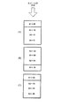
[0028]図1は、2つの密度を有する材料について、放射線曝露と放射線ビームの透過深度との関係を示す深度線量分布曲線である。曲線は、電子が2つの異なる密度、すなわち、より高い密度D1及びより低い密度D2を通って進む、材料の深度に対する線量を示す。図示するように、いずれの場合も、線量は最初に上昇し、次いで低下する。例えばD1のように材料の密度が高いほど、より急激に増加し、深度に対する線量レベルはより急激に減少する。例えば、密度D1を有することを特徴とするデバイスが40kGyで照射される場合、ピーク線量は44kGyであり、その後、例えば25kGyまで、最終的には、材料をさらに透過する0kGyまで低下する。より高い密度を有する材料の前面付近での急激な増加は、少なくとも一部には、入射電子と前面付近のより高密度の材料との衝突頻度の増加によって説明することができる。これにより、線量はピーク(44kGy)に達するまで急激に増加し、次いで、より深い深度を通って透過する電子の数が急激に減少するにつれて低下する。材料がより低い密度、すなわちD2であるとき、材料との最初の衝突がより少ないため、より多くの電子がより深く材料へと透過するように、よりゆっくりとピークに達し、線量の分布がより均一になる。 [0028] FIG. 1 is a depth dose distribution curve showing the relationship between radiation exposure and penetration depth of a radiation beam for a material having two densities. The curve shows the dose with respect to the depth of the material that the electrons travel through two different densities, namely a higher density D1 and a lower density D2. As shown, in either case, the dose first increases and then decreases. For example, the higher the material density, such as D1, increases more rapidly and the dose level with respect to depth decreases more rapidly. For example, when a device characterized by having a density D1 is irradiated at 40 kGy, the peak dose is 44 kGy and then drops to, for example, 25 kGy and eventually to 0 kGy, which further penetrates the material. The rapid increase near the front surface of the higher density material can be explained, at least in part, by the increased collision frequency between the incident electrons and the higher density material near the front surface. This causes the dose to increase rapidly until it reaches its peak (44 kGy) and then decreases as the number of electrons that penetrate through deeper depths decreases rapidly. When the material is at a lower density, ie D2, there will be less initial collisions with the material, so the peak will be reached more slowly so that more electrons will penetrate deeper into the material and the dose distribution will be more It becomes uniform.
[0029]本開示によると、線量レベルを放射線源に合わせて医療デバイスの向きで調整することによって、医療デバイスが受ける放射線線量の分散を低減する方法が提供される。本発明による方法は、以下のステップを含むことができる。最初に、デバイスは、質量の分布、すなわちデバイスの密度を説明する密度プロファイルによって特徴付けられる。密度プロファイルは、例えば、2、3又はそれ以上など、放射線源の前のパスの数、及びそれぞれのパスでの放射線源に対するデバイスの向きを示す。次いで、それぞれのパスの個々の線量マップが形成される。次いで、線量マップを取得した後、それぞれのパスの線量レベルが導き出される。線量レベルは、放射線源の前のすべてのパスの後、医療デバイスの異なる位置で受ける放射線レベルの総量の差異、すなわち分散を最小限化するように選択される。いくつかの実施形態では、密度プロファイルを決定するステップ又は線量レベルを決定するステップは必要ではなく、又は容易に明らかとなる。 [0029] According to the present disclosure, a method is provided for reducing the dispersion of the radiation dose received by a medical device by adjusting the dose level to the radiation source and the orientation of the medical device. The method according to the invention may comprise the following steps. Initially, the device is characterized by a mass profile that describes the distribution of mass, ie the density of the device. The density profile indicates the number of passes before the radiation source, eg, 2, 3 or more, and the orientation of the device relative to the radiation source in each pass. An individual dose map for each pass is then formed. Then, after obtaining a dose map, the dose level for each pass is derived. The dose level is selected to minimize the difference, i.e. dispersion, of the total amount of radiation received at different locations of the medical device after all passes before the radiation source. In some embodiments, determining the density profile or determining the dose level is not necessary or will be readily apparent.
[0030]図1に関して説明したように、デバイスに対する放射線線量の分散は、材料の質量がより大きい、すなわち、より高密度の部分に、より過剰になると予想される。したがって、材料が最も高密度である部分に、線量レベルの最大の分散が起きると予想される。より低密度の材料は、より均一の線量を受ける。したがって、低密度領域での線量レベルの差異についての懸念はより少なくなる。本発明者らは、デバイスを線量の分散を低減するように放射線に曝露する最良の方法を決定するとき、デバイスのより高密度な構成部品の分布を最も良く説明し、放射線源に対するデバイスの向きを最も良く示しもする多角形としてデバイスの形状を特徴付けることが、デバイスに対する線量レベルの分散を低減するためにしばしば有用であることを発見した。この「形状」は、先のパラグラフで述べた密度プロファイルと同じである。 [0030] As described with respect to FIG. 1, the distribution of radiation dose to the device is expected to be more excessive in higher mass portions, ie, higher density portions. Therefore, it is expected that the maximum dose level dispersion will occur in the densest part of the material. Lower density materials receive a more uniform dose. Therefore, there is less concern about the difference in dose level in the low density region. When we determine the best way to expose a device to radiation so as to reduce dose dispersion, we best describe the distribution of the denser components of the device and the orientation of the device relative to the radiation source. It has been found that characterizing the shape of the device as a polygon that also best represents is often useful to reduce the dispersion of dose levels for the device. This “shape” is the same as the density profile described in the previous paragraph.
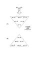
[0031]デバイスの密度プロファイルを図2に示す。密度プロファイルは全体的に多角形であり、それぞれの辺は、質量分布を説明するために、物体を放射線源に向けるべき方向を示す。比較的単純又は均一な密度を有する物体では、密度プロファイルは長方形であり、180度ずつの向きの2つのパスが、デバイスに対する線量の分散を適切に低減することが最もよくおこりやすいことを示している。より一般的な例では、密度プロファイルは、デバイスの放射線源の前のパスの数及びこれらのパスのそれぞれでのデバイスの向きとして理解し、又は表すことができる。 [0031] The density profile of the device is shown in FIG. The density profile is generally polygonal, with each side indicating the direction in which the object should be directed to the radiation source to account for the mass distribution. For objects with relatively simple or uniform density, the density profile is rectangular, indicating that two passes oriented 180 degrees each are most likely to adequately reduce dose distribution to the device. Yes. In a more general example, the density profile can be understood or represented as the number of passes before the radiation source of the device and the orientation of the device in each of these passes.
[0032]密度プロファイルの概念は、カテーテル製品の例を使用して説明することができる。このタイプの医療デバイスには、ポリマーバルーン、バルーンに取り付けられる生体吸収性ステント、及び遠位側及び近位側シャフト部分を含む複合材料デリバリーカテーテル部分を含む。これらの構成部品はすべて、密封された袋の中にパッケージされている。カテーテルの最も密度の高い部分は一般に、放射線源に面するとき別の上端には何も部品が置かれないと仮定すると、遠位端(バルーン及びステントが配置される部分)及びカテーテルシャフトの近位端である。平らに置かれるとき、デバイスの密度分布は、2辺の、長方形の形状又は密度プロファイルを有すると特徴付けることができる。 [0032] The concept of density profiles can be explained using examples of catheter products. This type of medical device includes a polymer balloon, a bioabsorbable stent attached to the balloon, and a composite material delivery catheter portion including distal and proximal shaft portions. All these components are packaged in a sealed bag. The most dense part of the catheter is generally near the distal end (the part where the balloon and stent are placed) and the catheter shaft, assuming no parts are placed at the other top when facing the radiation source. It is the end. When placed flat, the density distribution of the device can be characterized as having a two-sided, rectangular shape or density profile.
[0033]さらに示すように、図3は、物理的寸法は円盤状であるが、デバイス内により密度の高い構成部品を有する構成のために、放射線滅菌のための密度プロファイルは3辺の多角形である物体の密度分布を示す。したがって、寸法は円形であるが、放射線へのより均一な曝露を容易にするための密度プロファイルは、3辺の物体、すなわち三角形である。したがって、3辺のそれぞれが放射線源の前の3つのパスを画成し、正三角形の場合は、放射線源の前のパスがそれぞれ、デバイスを120度ずつ増加した向きに向ける。 [0033] As further shown, FIG. 3 shows that the physical profile is disk-shaped, but for a configuration with more dense components in the device, the density profile for radiation sterilization is a three-sided polygon. The density distribution of the object which is is shown. Thus, although the dimensions are circular, the density profile to facilitate a more uniform exposure to radiation is a three-sided object, ie a triangle. Thus, each of the three sides defines three paths in front of the radiation source, and in the case of an equilateral triangle, each path in front of the radiation source points the device in an increment of 120 degrees.
[0034]密度プロファイルが選択されると、次のステップは、デバイスの放射線源の前のそれぞれのパスにデバイスを線量マッピングすることである。最初に、デバイスが公称レベルの放射線に曝露されるときに受ける放射線線量を測定するために、線量計をデバイス上の位置に置く。入射ビームの放射線のレベルを測定するために、モニタリング線量計をデバイスの上流に配置する。線量マップは、デバイスが放射線に曝露されるときに受ける放射線の、モニタリング線量計レベルに対する相対的なレベルを示す。線量マップは、放射線源に対するデバイスのそれぞれの向きについて作製される。したがって、2辺の密度プロファイルでは(例えば、上記のカテーテルの例)2つの線量マップが作製される。第1の線量マップではデバイスの前面が放射線源に向いており、第2の線量マップではデバイスが180度反転している。図3の3辺の密度プロファイルでは、3つの線量マップが作製され、それぞれの線量マップは、放射線源に対するデバイスのそれぞれの向きで線量計が置かれる位置で受ける放射線の分布を示す。 [0034] Once the density profile is selected, the next step is to dose map the device to the respective path before the radiation source of the device. Initially, a dosimeter is placed in a position on the device to measure the radiation dose received when the device is exposed to a nominal level of radiation. A monitoring dosimeter is placed upstream of the device to measure the level of radiation in the incident beam. The dose map indicates the level of radiation received when the device is exposed to radiation relative to the monitoring dosimeter level. A dose map is created for each orientation of the device relative to the radiation source. Thus, for a two-sided density profile (eg, the catheter example above), two dose maps are created. In the first dose map, the front of the device is facing the radiation source, and in the second dose map the device is inverted 180 degrees. In the three-side density profile of FIG. 3, three dose maps are created, each showing the distribution of radiation received at the location where the dosimeter is placed in each orientation of the device relative to the radiation source.
[0035]線量計は、例えば、高密度の構成部品及び低密度の構成部品の後側など、線量レベルの分散を最も良く実現することができる位置に配置するべきである。線量計はまた、最大線量レベルを超えないようにするために正確な情報を利用できるように、より放射線感受性の高い材料、例えば、生体吸収性ポリマーの後側に置くべきである。線量マップを作製した後、1つの線量マップと別の線量マップを比較すると、密度プロファイルが不適切に作製されていることを示すことがある。このような場合、放射線源の前のデバイスの、異なる向き又はより多くの向き/パスを選択することができる。さらに、どの密度プロファイルが放射線滅菌のためにデバイスを最も良く特徴付けるかが明らかでない場合、線量マッピングの反復プロセス、次いで線量計によって検出される線量レベルの分布の比較を交互に使用して、放射線滅菌のためのデバイスの最良の向きを選択することができる。 [0035] The dosimeter should be placed in a location where dose level distribution can best be achieved, such as, for example, behind the dense and low density components. The dosimeter should also be placed behind a more radiation sensitive material, such as a bioabsorbable polymer, so that accurate information is available so as not to exceed the maximum dose level. After creating a dose map, comparing one dose map with another dose map may indicate that the density profile is being created improperly. In such cases, different orientations or more orientations / paths of the device in front of the radiation source can be selected. In addition, if it is not clear which density profile best characterizes the device for radiation sterilization, iteratively uses a dose mapping iterative process followed by a comparison of the distribution of dose levels detected by the dosimeter. The best orientation of the device for can be selected.
[0036]プロセスの次のステップは、いくつかの実施形態では任意であるが、すべてのパスの後の分散が最小限化されるように、放射線源の前のそれぞれのパスに照射する線量レベルを決定することである。対照的に、放射線滅菌の既存の方法では、例えば米国特許第6806476号のように、放射線源の前の2つのパスが使用されるとき、同じ線量を使用する。しかし、既存の方法を使用する線量レベルの分散は大きすぎるため、より狭い線量範囲を必要とする医療デバイスの照射には、これらのシステムは適切でない。放射線感受性材料を含む医療デバイスの滅菌のために、より多くの作業範囲を利用できるように、この分散を低減する必要がある。 [0036] The next step in the process is optional in some embodiments, but the dose level to irradiate each pass before the radiation source so that dispersion after all passes is minimized. Is to decide. In contrast, existing methods of radiation sterilization use the same dose when two passes in front of the radiation source are used, eg, US Pat. No. 6,806,476. However, these systems are not suitable for irradiation of medical devices that require a narrower dose range because the dispersion of dose levels using existing methods is too great. There is a need to reduce this dispersion so that more work area can be utilized for sterilization of medical devices containing radiation sensitive materials.
[0037]パスの数及びそれぞれのパスでのデバイスの向きを選択するために密度プロファイルを作製し、それぞれの向きの線量マップを比較することによって、線量レベルの最も小さい分散を生成するそれぞれのパスの線量レベルを決定するための情報が得られる。このデータはそれぞれのパスの線量マップから利用可能であり、3つのすべてのパスの後、すべての場所で線量の分散を最小限化する線量レベルを求めることができる。当業者であれば、このようにして生じる分散の問題の解決を見つけるために利用可能な、最小限化の数多くの数学的方法があることを理解するであろう。したがって、ここではそれらを詳細に説明する必要はない。 [0037] Each pass that produces the lowest variance in dose level by creating a density profile to select the number of passes and the orientation of the device in each pass and comparing the dose maps for each orientation Information is available to determine the dose level. This data is available from the dose map for each pass, and after all three passes, a dose level can be determined that minimizes dose distribution at all locations. Those skilled in the art will appreciate that there are a number of mathematical methods of minimization that can be used to find solutions to the dispersion problems that arise in this way. Therefore, they need not be described in detail here.
[0038]例示のために、2辺及び3辺の密度プロファイルによって特徴付けられるデバイスの例を使用する。図3及び図4の第1の例では、e−ビームの線量レベルがビームに対するデバイスの特定の向きに応じて選択されるとき、それぞれのパスに同じ線量を使用する場合と比較して、全体的な分散が低減されることが示されている。図5及び図6は、デバイスのより適切な密度プロファイルを選択することによって、分散の低減をどのように達成することができるかを示す。この例では、デバイスが、2つではなく、3つの方向で照射されるとき、分散が大幅に低減される。 [0038] For purposes of illustration, an example of a device characterized by two-sided and three-sided density profiles is used. In the first example of FIGS. 3 and 4, when the dose level of the e-beam is selected according to the specific orientation of the device with respect to the beam, the overall dose is compared to using the same dose for each pass. It has been shown that general dispersion is reduced. FIGS. 5 and 6 show how a reduction in dispersion can be achieved by selecting a more appropriate density profile for the device. In this example, dispersion is greatly reduced when the device is illuminated in three directions instead of two.
[0039]図3の(A)〜(C)及び図4の(A)〜(C)は、放射線源の前を2回通るカテーテル(2辺の密度プロファイル)の線量深度分布を示す。放射線ビームの方向は図3(A)及び図4(A)に示されており、それに続く図3(B)及び図3(C)、図4(B)及び図4(C)でも同様である。位置x1、x2、x3、及びx4は、例えばカテーテルの遠位端など、材料の質量の深さ方向の座標を示し、例えば、図3(A)に示された位置x1は、第1のパス後の線量レベルが25KGyであることに対応する。図はまた、図1に関して先に説明したように、低線量域及び高線量域も識別する。第1のパスでは、位置x1は高線量域にあり、第2のパスではx4は高線量域にある。 [0039] FIGS. 3A-C and 4A-4C show the dose depth distribution of a catheter (two-sided density profile) that passes twice in front of the radiation source. The direction of the radiation beam is shown in FIGS. 3 (A) and 4 (A), and the same applies to FIGS. 3 (B), 3 (C), 4 (B), and 4 (C). is there. Positions x1, x2, x3, and x4 indicate the depth coordinates of the mass of the material, such as the distal end of the catheter, for example, position x1 shown in FIG. This corresponds to a later dose level of 25 KGy. The figure also identifies low and high dose areas as described above with respect to FIG. In the first pass, position x1 is in the high dose range and in the second pass x4 is in the high dose range.
[0040]図3の(A)〜(C)は、両方のパスでデバイスの構成部品又はデバイスが25KGyの線量で照射されるとき、深さx1、x2、x3、及びx4で受ける線量レベルを示す。図4の(A)〜(C)は、同じデバイスであるが第1のパスでは30KGy線量、第2のパスでは20KGy線量で照射されるとき、x1、x2、x3、及びx4で受ける線量レベルを示す(第1の向きの高線量域内の材料の第1の密度は、第2の向きの高線量域内の材料の第2の密度より高いため、第1の線量レベルは第2の線量レベルに対して低減されている)。第2のパスでは、x1、x2、x3及びx4の位置から推測することができるように、デバイスは180度反転される。図3(A)及び図4(A)は、第1のパス後の線量レベルを示す。デバイスが180度反転されるときに受ける線量レベルは、図3(B)及び図4(B)に示されている。図3(C)及び図4(C)は、それぞれのパスのそれぞれの位置の線量レベルを加算することによって得られる、両方のパス後のそれぞれの位置x1、x2、x3、及びx4における合計された線量レベルを示す。本発明によって可能になる線量レベルの分散の低減は、図3(C)の最終的な線量レベルと図4(C)の最終的な線量レベルを比較すると分かる。 [0040] FIGS. 3A-C show the dose levels received at depths x1, x2, x3, and x4 when the device components or devices are irradiated at a dose of 25 KGy in both passes. Show. FIGS. 4A to 4C show the same device but the dose levels received at x1, x2, x3, and x4 when irradiated with a 30 KGy dose in the first pass and a 20 KGy dose in the second pass. (The first dose level is the second dose level because the first density of the material in the high dose region in the first orientation is higher than the second density of the material in the high dose region in the second orientation. Against)). In the second pass, the device is flipped 180 degrees so that it can be inferred from the x1, x2, x3 and x4 positions. 3A and 4A show the dose level after the first pass. The dose level received when the device is turned 180 degrees is shown in FIGS. 3 (B) and 4 (B). FIGS. 3C and 4C are summed at the respective positions x1, x2, x3, and x4 after both passes, obtained by adding the dose levels at the respective positions of the respective passes. Dose level. The reduction in dose level dispersion enabled by the present invention can be seen by comparing the final dose level of FIG. 3C with the final dose level of FIG. 4C.
[0041]放射線損傷が起きる前の図3及び図4のカテーテルの線量限度が40KGyであり、SAL10−6のための最小線量レベルが25KGyであると仮定する。図3(C)のx1〜x4の線量レベルを比較することによって分かるように、同じ線量レベル(25KGy)が照射されるときの線量レベルの分散は10KGyである。SAL10−6のための最小線量レベル(25KGy)が1つの位置で達成され、最大線量の35KGyが他の位置で達成される。したがって、すべての位置でデバイスのバイオバーデンを適切に低減するために、操作者は、5KGyの動作範囲でしか作業することができない(40−35=5KGy)。これは狭い動作範囲であり、先に説明したように、滅菌プロセスが複雑になる。おそらく、より重要なことは、利用可能な動作範囲の上限が5KGyしかない場合、この動作範囲内でのビームパラメータの制御が困難であるため、又は、ある位置で受ける実際の線量が線量マップから予想され、又は示唆されるものより高いためのいずれかによって、デバイスが損傷する危険性がより高くなることである。 [0041] dose limit of the catheter of FIG. 3 and FIG. 4 before the radiation damage occurs is 40 KGy, it is assumed that the minimum dose level for SAL10 -6 is 25 KGy. As can be seen by comparing the dose levels x1 to x4 in FIG. 3C, the dose level variance when the same dose level (25 KGy) is irradiated is 10 KGy. Minimum dose level for SAL10 -6 (25KGy) is achieved in one position, 35 KGy the maximum dose is reached at other locations. Thus, in order to properly reduce the bioburden of the device at all positions, the operator can only work in the operating range of 5 KGy (40−35 = 5 KGy). This is a narrow operating range and, as explained above, complicates the sterilization process. Perhaps more importantly, if the upper limit of the available operating range is only 5 KGy, it is difficult to control the beam parameters within this operating range, or the actual dose received at a location from the dose map Either because it is higher than expected or suggested, there is a higher risk of damage to the device.
[0042]図4(C)は、比較として、より好ましい4KGyの線量分散を示し(x3とx4を比較)、最小線量レベルが30KGy、及び最大線量が34KGyであることを示す。本発明の方法を使用すると、動作範囲の下限は5KGy、動作範囲の上限は6KGyである。動作範囲が広いほど、40KGyの上限を超えることなく、SALを達成するようにビームを制御することがより簡単になる。動作範囲がより広いことよって、操作者が、図3の(A)〜(C)の場合より、ビーム線量レベルと上限とのより大きい間隔を得ることができ、操作者はデバイスが受ける実際の線量レベルの不確実性をより多く考慮に入れることができる。 [0042] FIG. 4 (C) shows a more preferred 4 KGy dose variance (compare x3 and x4) for comparison, showing that the minimum dose level is 30 KGy and the maximum dose is 34 KGy. Using the method of the present invention, the lower limit of the operating range is 5 KGy and the upper limit of the operating range is 6 KGy. The wider the operating range, the easier it is to control the beam to achieve SAL without exceeding the upper limit of 40 KGy. Because of the wider operating range, the operator can obtain a larger distance between the beam dose level and the upper limit than in the case of FIGS. More uncertainty in dose level can be taken into account.
[0043]図5の(A)〜(C)及び図6の(A)〜(B)は、図2の円盤状の形状のデバイスの線量深度分布を示す。先に説明したように、放射線滅菌では、円盤形は、より密度の高い構成部品がこのように配置されているとき、以下の説明からより詳しく理解されるように、3辺の物体として最も良く示される。図5の(A)〜(C)は、同じ線量レベルで2つのパス後の線量レベルを示す。デバイスは、当技術分野では一般的であるが、より密度の高い構成部品がデバイス内にある配置にかかわらず、第1のパス後に180度反転される。上記のように、ビーム方向が示され、深さ方向の座標y1、y2、y3…y6における線量レベルが示されている。25KGy線量がそれぞれのパスに照射される。図5(A)を参照すると、y1は第1のパスの高線量域にある。第2のパスでは、y3、y4及びy5はそれぞれ高線量域にある(デバイスはパス間で180度反転される)。図6の(A)〜(B)は、同じデバイスであるがそれぞれ120度ずつ離れた3つの異なる向きで、それぞれのパスで同じ線量レベル(17KGy)で、放射線に曝露されるときの線量レベルを示す。3辺の密度プロファイルに合わせて、3つのパスが形成される。ビーム方向は、図示するように、図6(A)の三角形の各辺に対して垂直である。この例では、それぞれの向きに同じ線量レベルを照射することができる。3辺の密度プロファイルを有する、又は3辺の密度プロファイルに最も近い医療デバイスでは、後でより詳細に説明するが、線量レベルの分散を最小限化するために、それぞれのパスで線量レベルを異なるものにすることができる。 [0043] FIGS. 5 (A)-(C) and FIGS. 6 (A)-(B) show the dose depth distribution of the disk-shaped device of FIG. As explained above, in radiation sterilization, the disk shape is best as a three-sided object when more dense components are arranged in this way, as will be understood in more detail from the following description. Indicated. 5A to 5C show the dose level after two passes at the same dose level. The device is common in the art, but is flipped 180 degrees after the first pass, regardless of the arrangement in which the denser components are in the device. As described above, the beam direction is shown, and the dose levels at the coordinates y1, y2, y3... Y6 in the depth direction are shown. A 25 KGy dose is applied to each pass. Referring to FIG. 5A, y1 is in the high dose range of the first pass. In the second pass, y3, y4 and y5 are each in the high dose range (the device is inverted 180 degrees between passes). 6 (A)-(B) show the dose level when exposed to radiation at the same dose level (17 KGy) in each pass in the same device but in three different orientations, each 120 degrees apart. Indicates. Three passes are formed according to the density profile of the three sides. As shown, the beam direction is perpendicular to each side of the triangle in FIG. In this example, the same dose level can be irradiated in each direction. For medical devices having a three-sided density profile or closest to the three-sided density profile, which will be described in more detail later, the dose level is different for each pass to minimize dose level dispersion. Can be a thing.
[0044]放射線損傷が起きる前の図5及び図6の円盤形の線量限度が50KGyであり、SAL10−6のための最小線量レベルが25KGyであると仮定する。図5(C)のy1〜y5の線量レベルを比較することによって分かるように、同じ線量レベル(25KGy)が照射されるときの線量レベルの分散は20KGyであり、最小線量レベルが30KGy、及び最大線量が50KGyであり、それが限度である。したがって、すべての位置でSAL10−6を得るために、操作者は、やはり5KGyの動作範囲でしか作業することができない。図6(B)は、比較として、はるかに好ましい0KGyのみの線量分散を示し、線量レベルはすべての位置で37KGyである。したがって、本発明の方法を使用すると、この例ではデバイスの密度プロファイルに基づいて向きを選択する場合、既存の技術を使用する5KGyの場合と比較して、25KGyの動作範囲が利用可能になる。 [0044] dose limit of the disc-shaped in FIG. 5 and 6 before the radiation damage occurs is 50 KGy, it is assumed that the minimum dose level for SAL10 -6 is 25 KGy. As can be seen by comparing the dose levels of y1 to y5 in FIG. 5C, the dose level variance when irradiated with the same dose level (25 KGy) is 20 KGy, the minimum dose level is 30 KGy, and the maximum The dose is 50 KGy, which is the limit. Therefore, in order to obtain a SAL10 -6 at every position, the operator can not still be working only in the operating range of 5 kGy. FIG. 6B shows, by comparison, a much more preferred dose distribution of 0 KGy only, with a dose level of 37 KGy at all positions. Thus, using the method of the present invention, an operating range of 25 KGy is available in this example when selecting an orientation based on the density profile of the device compared to 5 KGy using existing technology.
[0045]上記で説明した例では、それぞれの向きに同じ線量レベルが照射される。より一般的な場合では、図2の円盤形の場合のように分散を低減するという目的に対してそれほど好ましい密度分布を得ることは不可能であろう。構成部品はより離れているので、密度プロファイルは多角形によって分布を大まかに概算することしかできない。このような場合、分散を低減するために、例えば、4、5、6、又はそれ以上など、パスの数を増加することができる。さらに、それぞれのパスは、放射線源の前のすべてのパスが形成された後の分散の総量を最小限化するように選択された、独自の特有の線量レベルを有することができるが、上記の例が示すように、いくつかのデバイスでは、向きを適切に選択すると、それぞれのパスで線量レベルを調整する必要がなくなることが企図されており、これは望ましいことである。 [0045] In the example described above, the same dose level is irradiated in each direction. In the more general case, it would not be possible to obtain a density distribution that is so favorable for the purpose of reducing dispersion, as in the case of the disk shape of FIG. Since the components are more distant, the density profile can only roughly approximate the distribution by polygons. In such cases, the number of paths can be increased, eg, 4, 5, 6, or more, to reduce dispersion. In addition, each pass can have its own unique dose level, selected to minimize the total amount of dispersion after all previous passes of the radiation source are formed, As the examples show, for some devices it is contemplated that proper selection of orientation eliminates the need to adjust the dose level in each pass.
[0046]最小限化は、線量マップで選択されたすべての位置、又は最大及び最小になる位置に対する分散に基づいて、行うことができる。したがって、第1の線量計の位置(第1のデバイスの位置付近のデバイスの線量レベルを予測する)と第2の線量計の位置(第2のデバイスの位置付近のデバイスの線量レベルを予測する)との差異を最小限化するように、それぞれのパスの線量レベルとパスの数の両方又は一方を選択することができる。又は、それぞれのパスの線量レベルとパスの数の両方又は一方は、例えば、デバイス上の2つの位置だけでなく、線量マップを構成するすべての線量計にわたる、又はすべての線量計に対する線量分散を最小限化し、すなわち、デバイス全体に対する分散を最小限化するように、選択することができる。 [0046] Minimization can be performed based on the variance for all locations selected in the dose map, or for the maximum and minimum locations. Thus, the position of the first dosimeter (predicts the dose level of the device near the position of the first device) and the position of the second dosimeter (predicts the dose level of the device near the position of the second device). ) And / or the number of passes and / or the number of passes can be selected to minimize the difference between Or, the dose level and / or number of passes for each pass may be the dose distribution across or for all dosimeters that make up the dose map, not just two locations on the device, for example. It can be chosen to minimize, i.e. minimize the variance over the entire device.
[0047]4つのパスを適用するデバイスでは、デバイスに対する分布を決定するために、4つの向きに、例えば90度回転で、4つの線量マップが作製され、次いで、4つのパスがすべて完了した後のデバイスに対する総分散量を最小限化するように、それぞれのパスの線量レベルが計算される。同様に、6つのパスでは、デバイスに対する分布を決定するために、6つの向きのそれぞれに、例えば60度回転で、6つの線量マップが作製され、次いで、6つのパスがすべて完了した後のデバイスに対する総分散量を最小限化するように、それぞれのパスの線量レベルが計算される。 [0047] In a device that applies four passes, four dose maps are created in four orientations, eg, 90 degrees rotation, to determine the distribution for the device, and then after all four passes are complete The dose level for each pass is calculated to minimize the total amount of dispersion for the devices. Similarly, in six passes, six dose maps are created in each of the six orientations, eg, rotated 60 degrees, to determine the distribution for the device, and then the device after all six passes have been completed. The dose level for each pass is calculated to minimize the total variance for.
[0048]より一般的な場合について、線量マップにおける「m」個の線量計位置のパスの数を「n」とすると、線量レベルを求める数学的問題に対する解は、m次方程式を使用して求められる未知数nの1つになり、例えば、m次式はそれぞれ、少なくとも最初は、m個の線量計位置のそれぞれにおける線量レベルの合計として、未知数n(線量レベル)のそれぞれについて表すことができる。結果として得られる式(例えば、線量計位置の総線量の差異)は、一般に、線量レベルを求める式の過剰決定された組となる(放射線源の前のパスより線量計位置のほうが多いことがあるので、求めようとする未知数より多くの式が存在する)。これはもちろん、それぞれの式が他の式に対して線形独立であることを示している。特に、式が線形従属である場合、デバイスの密度プロファイルは、洞察が得られ、線形従属性は放射線源の前のより少ないパスで十分であることを示唆している。理解されるように、分散問題の最小限化について上記で提案したような数式及び解は、当技術分野では周知である。 [0048] For the more general case, if the number of passes of “m” dosimeter positions in the dose map is “n”, then the solution to the mathematical problem to determine the dose level is One of the required unknowns n, for example, each m-th order equation can be represented for each of the unknowns n (dose levels) at least initially as the sum of the dose levels at each of the m dosimeter positions. . The resulting formula (eg, the difference in total dose at the dosimeter position) is typically an over-determined set of formulas for determining the dose level (the dosimeter position may be more than the previous path of the radiation source). There are more equations than unknowns to be found). This of course indicates that each equation is linearly independent of the other equations. In particular, if the equation is linearly dependent, the density profile of the device gives insight, suggesting that linearity is sufficient with fewer passes in front of the radiation source. As will be appreciated, the equations and solutions as proposed above for minimizing the dispersion problem are well known in the art.
[0049]以上、本発明の特定の実施形態を図示し説明したが、本開示を読めば、本発明のより広い解釈において、本発明から逸脱することなく、変更及び修正を行うことができることを当業者であれば理解するであろう。 [0049] While specific embodiments of the invention have been illustrated and described, upon reading the present disclosure, changes and modifications can be made without departing from the invention in a broader interpretation of the invention. Those skilled in the art will understand.
Claims (9)
医療デバイスの公称線量レベルへの曝露に基づいて、前記医療デバイスの第1の線量マップ及び第2の線量マップを取得するステップであって、前記第1の線量マップを取得するために前記医療デバイスを放射線源に対して第1の向きで配置し、前記医療デバイスが受ける実際の放射線量を測定するサブステップと、前記第2の線量マップを取得するために前記医療デバイスを放射線源に対して第2の向きで配置し、前記医療デバイスが受ける実際の放射線量を測定するサブステップと、を含む、当該医療デバイスの第1の線量マップ及び第2の線量マップを取得するステップと、
前記第1の線量マップ及び前記第2の線量マップのそれぞれによって説明される密度プロファイルに基づいて、前記放射線源からの放射線の大きさである第1の線量レベル及び第2の線量レベルを選択するステップであって、前記第2の線量レベルが前記第1の線量レベルと異なっている、当該選択するステップと、
前記医療デバイスを滅菌するステップであって、前記医療デバイスを前記第1の向きで配置するサブステップと、次いで前記医療デバイスを前記第1の線量レベルに曝露するサブステップと、前記医療デバイスを前記第2の向きで配置するサブステップと、次いで前記医療デバイスを前記第2の線量レベルに曝露するサブステップと、を含む、当該医療デバイスを滅菌するステップと、
を備え、
前記医療デバイス上のある位置で受ける総放射線量は、前記第1の線量レベル及び前記第2の線量レベルへの曝露後に前記ある位置で受ける放射線の総計であり、
前記選択するステップは、前記医療デバイス上の第1の位置で受ける前記総放射線量と前記医療デバイス上の第2の位置で受ける前記総放射線量との違いを減らすように、前記第1の線量レベル及び前記第2の線量レベルを決定することを含む、当該方法。 A method of sterilizing a medical device by irradiation with a radiation source that operates within a limited operating range that achieves a sterility assurance level and does not damage the medical device,
Obtaining a first dose map and a second dose map of the medical device based on exposure of the medical device to a nominal dose level, the medical device for obtaining the first dose map; In a first orientation with respect to the radiation source and measuring the actual radiation dose received by the medical device, and the medical device relative to the radiation source to obtain the second dose map Obtaining a first dose map and a second dose map of the medical device, comprising: a sub-step of positioning in a second orientation and measuring the actual radiation dose received by the medical device;
Based on the density profile described by each of the first dose map and the second dose map, the radiation of Ru magnitude der first dose level及beauty second dose level from said radiation source Selecting, wherein the second dose level is different from the first dose level; and
Sterilizing the medical device, the sub-step of placing the medical device in the first orientation; and the sub-step of exposing the medical device to the first dose level; Sterilizing the medical device, comprising: sub-positioning in a second orientation; and then sub-exposing the medical device to the second dose level;
With
The total radiation dose received at a location on the medical device is the total amount of radiation received at the location after exposure to the first dose level and the second dose level;
The selecting step includes reducing the difference between the total radiation dose received at a first location on the medical device and the total radiation dose received at a second location on the medical device. Determining the level and the second dose level.
前記第1の線量レベルが第1のパス中に照射され、前記医療デバイスが向きを変えられ、次いで前記第2の線量レベルが第2のパス中に照射される、請求項1に記載の方法。 The step of sterilizing the medical device moves the medical device along a conveyor at a predetermined speed based on a desired dose level,
The method of claim 1, wherein the first dose level is irradiated during a first pass, the medical device is turned, and then the second dose level is irradiated during a second pass. .
前記選択するステップは、前記第1の線量マップ、前記第2の線量マップ、及び前記第3の線量マップのそれぞれによって説明される密度プロファイルに基づいて、前記第1の線量レベル、前記第2の線量レベル、及び第3の線量レベルを選択することを含み、
前記滅菌するステップは、前記医療デバイスを前記第1の向きで配置するサブステップと、次いで前記医療デバイスを前記第1の線量レベルに曝露するサブステップと、前記医療デバイスを前記第2の向きで配置するサブステップと、次いで前記医療デバイスを前記第2の線量レベルに曝露するサブステップと、前記医療デバイスを前記第3の向きで配置するサブステップと、次いで前記医療デバイスを前記第3の線量レベルに曝露するサブステップとを含み、
前記医療デバイス上のある位置で受ける総放射線量は、前記第1の線量レベル、前記第2の線量レベル、及び前記第3の線量レベルへの曝露後に前記ある位置で受ける放射線の総計であり、
前記選択するステップは、前記第1の線量レベル、前記第2の線量レベル、及び前記第3の線量レベルの全ての組合せによって、高密度のエリアで受ける線量と低密度のエリアで受ける線量との違いを減らすように、前記第1の線量レベル、前記第2の線量レベル、及び前記第3の線量レベルを決定することを含む、請求項1に記載の方法。 The obtaining step further comprises positioning the medical device in a third orientation relative to the radiation source to obtain a third dose map;
The selecting step includes the first dose level, the second dose level based on a density profile described by each of the first dose map, the second dose map, and the third dose map. Selecting a dose level, and a third dose level,
The sterilizing step includes a sub-step of placing the medical device in the first orientation, a sub-step of exposing the medical device to the first dose level, and the medical device in the second orientation. A sub-step of placing, then a sub-step of exposing the medical device to the second dose level, a sub-step of placing the medical device in the third orientation, and then placing the medical device in the third dose A sub-step exposing to the level,
The total radiation dose received at a location on the medical device is the total amount of radiation received at the location after exposure to the first dose level, the second dose level, and the third dose level;
The step of selecting includes the dose received in the high density area and the dose received in the low density area by all combinations of the first dose level, the second dose level, and the third dose level. The method of claim 1, comprising determining the first dose level, the second dose level, and the third dose level to reduce differences.
前記第1の線量レベルが第1のパス中に照射され、前記医療デバイスが向きを変えられ、次いで前記第2の線量レベルが第2のパス中に照射され、次いで前記医療デバイスが前記第3の向きで配置され、次いで前記第3の線量レベルが第3のパス中に照射される、請求項6に記載の方法。 The sterilizing step includes moving the medical device along a conveyor at a predetermined speed based on a desired dose level;
The first dose level is irradiated during a first pass, the medical device is turned, then the second dose level is irradiated during a second pass, and then the medical device is the third pass. The method of claim 6, wherein the third dose level is irradiated during a third pass.
Applications Claiming Priority (3)
| Application Number | Priority Date | Filing Date | Title |
|---|---|---|---|
| US12/753,830 | 2010-04-02 | ||
| US12/753,830 US8981316B2 (en) | 2010-04-02 | 2010-04-02 | Radiation sterilization of implantable medical devices |
| PCT/US2011/029815 WO2011123327A1 (en) | 2010-04-02 | 2011-03-24 | Radiation sterilization of implantable medical devices |
Publications (3)
| Publication Number | Publication Date |
|---|---|
| JP2013523268A JP2013523268A (en) | 2013-06-17 |
| JP2013523268A5 JP2013523268A5 (en) | 2015-05-28 |
| JP6202497B2 true JP6202497B2 (en) | 2017-09-27 |
Family
ID=43970863
Family Applications (1)
| Application Number | Title | Priority Date | Filing Date |
|---|---|---|---|
| JP2013502660A Expired - Fee Related JP6202497B2 (en) | 2010-04-02 | 2011-03-24 | Radiation sterilization of implantable medical devices |
Country Status (4)
| Country | Link |
|---|---|
| US (2) | US8981316B2 (en) |
| EP (1) | EP2552495B1 (en) |
| JP (1) | JP6202497B2 (en) |
| WO (1) | WO2011123327A1 (en) |
Families Citing this family (3)
| Publication number | Priority date | Publication date | Assignee | Title |
|---|---|---|---|---|
| US8981316B2 (en) * | 2010-04-02 | 2015-03-17 | Abbott Cardiovascular Systems Inc. | Radiation sterilization of implantable medical devices |
| JP2022510458A (en) * | 2018-12-07 | 2022-01-26 | ジェルミテック | Modeling to assist in high-level UV-C disinfection |
| US11896726B1 (en) * | 2021-02-11 | 2024-02-13 | Lockheed Martin Corporation | Interactive ultraviolet decontamination system |
Family Cites Families (43)
| Publication number | Priority date | Publication date | Assignee | Title |
|---|---|---|---|---|
| US695116A (en) * | 1900-09-21 | 1902-03-11 | Wilfred I Ohmer | Ticket issuing, printing, and recording machine. |
| US795857A (en) * | 1902-11-19 | 1905-08-01 | H C Rehn | Method and means of signaling. |
| US3916204A (en) * | 1974-05-03 | 1975-10-28 | Western Electric Co | Irradiating elongated material |
| US5226065A (en) * | 1989-10-13 | 1993-07-06 | Stericycle, Inc. | Device for disinfecting medical materials |
| JPH04108451A (en) * | 1990-08-29 | 1992-04-09 | Rajie Kogyo Kk | Method for enhancing reliability of electron beam irradiation |
| JPH08151021A (en) * | 1994-11-30 | 1996-06-11 | Iwasaki Electric Co Ltd | Method of sterilizing container |
| CA2159531A1 (en) * | 1995-09-29 | 1997-03-30 | Courtland B. Lawrence | Method for monitoring absorbed dose in an electron beam |
| JP3042457B2 (en) * | 1997-08-21 | 2000-05-15 | 日本電気株式会社 | Multi-layer ATM communication device |
| US6157028A (en) * | 1998-05-28 | 2000-12-05 | Jrh Biosciences, Inc. | Method for dose mapping to ensure proper amounts of gamma irradiation |
| US6215847B1 (en) | 1998-09-15 | 2001-04-10 | Mds Nordion Inc. | Product irradiator |
| JP2000167029A (en) * | 1998-12-01 | 2000-06-20 | Mitsubishi Electric Corp | Irradiator |
| JP2000325440A (en) * | 1999-05-21 | 2000-11-28 | Mitsubishi Heavy Ind Ltd | Electron beam irradiation method |
| JP2000325434A (en) * | 1999-05-21 | 2000-11-28 | Mitsubishi Heavy Ind Ltd | Electron beam irradiating device |
| JP2000334028A (en) | 1999-05-26 | 2000-12-05 | Ishikawajima Harima Heavy Ind Co Ltd | Method for sterilizing medical supplies by electron beam |
| JP2001025501A (en) * | 1999-07-13 | 2001-01-30 | Mitsubishi Electric Corp | Radiation apparatus |
| SE514967C2 (en) * | 1999-09-17 | 2001-05-21 | Tetra Laval Holdings & Finance | System for monitoring and controlling when sterilizing an object |
| US6713773B1 (en) * | 1999-10-07 | 2004-03-30 | Mitec, Inc. | Irradiation system and method |
| US6504898B1 (en) * | 2000-04-17 | 2003-01-07 | Mds (Canada) Inc. | Product irradiator for optimizing dose uniformity in products |
| JP2002000705A (en) * | 2000-06-26 | 2002-01-08 | Mitsubishi Heavy Ind Ltd | Electron beam radiating apparatus of medical apparatus |
| US6617596B1 (en) | 2000-11-17 | 2003-09-09 | Steris Inc. | On-line measurement of absorbed electron beam dosage in irradiated product |
| JP2002221598A (en) * | 2001-01-26 | 2002-08-09 | Mitsubishi Electric Corp | Electron beam irradiation system, and x-ray irradiation system |
| US6762418B2 (en) * | 2001-03-13 | 2004-07-13 | Advanced Cardiovascular Systems, Inc. | Calorimetry as a routine dosimeter at an electron beam processing facility |
| US6885011B2 (en) * | 2001-04-02 | 2005-04-26 | Mitec Incorporated | Irradiation system and method |
| US20030021722A1 (en) | 2001-07-24 | 2003-01-30 | Allen John Thomas | System for, and method of, irradiating articles |
| AU2002360853A1 (en) * | 2001-12-31 | 2003-07-24 | Lockheed Martin Corporation | System and method of detecting, neutralizing, and containing suspected contaminated articles |
| US7175806B2 (en) * | 2002-03-15 | 2007-02-13 | Deal Jeffery L | C-band disinfector |
| US6806476B2 (en) | 2002-05-21 | 2004-10-19 | Ion Beam Applications, S.A. | Irradiation facility control system |
| WO2004013889A1 (en) * | 2002-08-05 | 2004-02-12 | Electron Processing Systems, Inc. | Process for electron sterilization of a container |
| US6919572B2 (en) | 2003-05-02 | 2005-07-19 | The Titan Corporation | Compensating for variations in article speeds and characteristics at different article positions during article irradiation |
| JP2004347510A (en) * | 2003-05-23 | 2004-12-09 | Toyo Ink Mfg Co Ltd | Device and method for irradiation with electron beam and object irradiated with electron beam |
| US7588803B2 (en) * | 2005-02-01 | 2009-09-15 | Applied Materials, Inc. | Multi step ebeam process for modifying dielectric materials |
| US7375345B2 (en) * | 2005-10-26 | 2008-05-20 | Tetra Laval Holdings & Finance S.A. | Exposed conductor system and method for sensing an electron beam |
| ES2395112T3 (en) * | 2006-02-07 | 2013-02-08 | Tepha, Inc. | Cured polylactic acid polymers and copolymers |
| US20090076594A1 (en) * | 2006-03-14 | 2009-03-19 | Patrick Sabaria | Method of monitoring positioning of polymer stents |
| US8034287B2 (en) | 2006-06-01 | 2011-10-11 | Abbott Cardiovascular Systems Inc. | Radiation sterilization of medical devices |
| US7998404B2 (en) | 2006-07-13 | 2011-08-16 | Advanced Cardiovascular Systems, Inc. | Reduced temperature sterilization of stents |
| US8747738B2 (en) * | 2006-08-15 | 2014-06-10 | Abbott Cardiovascular Systems Inc. | Sterilization methods for medical devices |
| US7959857B2 (en) * | 2007-06-01 | 2011-06-14 | Abbott Cardiovascular Systems Inc. | Radiation sterilization of medical devices |
| US9011894B2 (en) * | 2007-06-29 | 2015-04-21 | Carbylan Therapeutics, Inc. | Sterile hyaluronic acid polymer compositions and related methods |
| DE102008007662A1 (en) * | 2008-02-06 | 2009-08-13 | Robert Bosch Gmbh | Apparatus and method for the treatment of moldings by means of high-energy electron beams |
| WO2010002995A2 (en) * | 2008-07-01 | 2010-01-07 | The Texas A&M University System | Maxim electron scatter chamber |
| DE102008045187A1 (en) * | 2008-08-30 | 2010-03-04 | Krones Ag | Electron beam sterilization for containers |
| US8981316B2 (en) * | 2010-04-02 | 2015-03-17 | Abbott Cardiovascular Systems Inc. | Radiation sterilization of implantable medical devices |
-
2010
- 2010-04-02 US US12/753,830 patent/US8981316B2/en not_active Expired - Fee Related
-
2011
- 2011-03-24 EP EP11712428.9A patent/EP2552495B1/en not_active Not-in-force
- 2011-03-24 WO PCT/US2011/029815 patent/WO2011123327A1/en active Application Filing
- 2011-03-24 JP JP2013502660A patent/JP6202497B2/en not_active Expired - Fee Related
-
2015
- 2015-02-11 US US14/620,090 patent/US9339569B2/en not_active Expired - Fee Related
Also Published As
| Publication number | Publication date |
|---|---|
| US20150217009A1 (en) | 2015-08-06 |
| WO2011123327A1 (en) | 2011-10-06 |
| US9339569B2 (en) | 2016-05-17 |
| EP2552495A1 (en) | 2013-02-06 |
| EP2552495B1 (en) | 2016-12-21 |
| US8981316B2 (en) | 2015-03-17 |
| JP2013523268A (en) | 2013-06-17 |
| US20110240882A1 (en) | 2011-10-06 |
Similar Documents
| Publication | Publication Date | Title |
|---|---|---|
| Dogan et al. | Comparative evaluation of Kodak EDR2 and XV2 films for verification of intensity modulated radiation therapy | |
| US7959857B2 (en) | Radiation sterilization of medical devices | |
| Lambert et al. | Radiation and ethylene oxide terminal sterilization experiences with drug eluting stent products | |
| Kanjickal et al. | Effects of sterilization on poly (ethylene glycol) hydrogels | |
| JP6202497B2 (en) | Radiation sterilization of implantable medical devices | |
| Harrington et al. | Sterilization and disinfection of biomaterials for medical devices | |
| Kan et al. | The accuracy of dose calculations by anisotropic analytical algorithms for stereotactic radiotherapy in nasopharyngeal carcinoma | |
| Darwis et al. | Radiation processing of polymers for medical and pharmaceutical applications | |
| Domańska et al. | Sterilization process of polyester based anticancer-drug delivery systems | |
| JP6139512B2 (en) | Method for stabilizing the molecular weight of a polymer stent after sterilization | |
| Parsons | Sterilisation of healthcare products by ionising radiation: principles and standards | |
| JP6183808B2 (en) | Post-electron beam stabilization of polymer medical devices | |
| Adlienė et al. | First approach to ionizing radiation based 3D printing: fabrication of free standing dose gels using high energy gamma photons | |
| Hartmann et al. | Dosimetric characterization of a new miniature multileaf collimator | |
| Lambert et al. | Chapter III. 1.2-Sterilization of Implants and Devices | |
| Bargh et al. | The effects of gamma and microwave sterilization on periodontological grafts | |
| US20110281022A1 (en) | Methods For Controlling The Release Rate And Improving The Mechanical Properties Of A Stent Coating | |
| JP2013523268A5 (en) | ||
| Kamberi et al. | Stability testing of drug eluting stents | |
| Özgüven et al. | An institutional experience of quality assurance of a treatment planning system on photon beam | |
| Sharma et al. | Achieving sterility in biomedical and pharmaceutical products (part-II): radiation sterilization | |
| Valdetaro et al. | Investigation of the dose rate and linear-energy-transfer of the signal quenching of radiochromic silicone-based dosimeters for different curing times and compositions | |
| Parsons | Sterilisation procedures for tissue allografts | |
| Shalaby et al. | Radiochemical sterilization and its use for sutures | |
| Firmansyah et al. | Comparison of Hi-Art Tomotherapy Machine Outputs Using AAPM TG-148 and IAEA TRS 483 Codes of Practice |
Legal Events
| Date | Code | Title | Description |
|---|---|---|---|
| A621 | Written request for application examination |
Free format text: JAPANESE INTERMEDIATE CODE: A621 Effective date: 20140115 |
|
| A977 | Report on retrieval |
Free format text: JAPANESE INTERMEDIATE CODE: A971007 Effective date: 20141219 |
|
| A131 | Notification of reasons for refusal |
Free format text: JAPANESE INTERMEDIATE CODE: A131 Effective date: 20150106 |
|
| A524 | Written submission of copy of amendment under section 19 (pct) |
Free format text: JAPANESE INTERMEDIATE CODE: A524 Effective date: 20150406 |
|
| A131 | Notification of reasons for refusal |
Free format text: JAPANESE INTERMEDIATE CODE: A131 Effective date: 20151020 |
|
| A601 | Written request for extension of time |
Free format text: JAPANESE INTERMEDIATE CODE: A601 Effective date: 20160112 |
|
| A521 | Written amendment |
Free format text: JAPANESE INTERMEDIATE CODE: A523 Effective date: 20160217 |
|
| A02 | Decision of refusal |
Free format text: JAPANESE INTERMEDIATE CODE: A02 Effective date: 20160426 |
|
| A521 | Written amendment |
Free format text: JAPANESE INTERMEDIATE CODE: A523 Effective date: 20160824 |
|
| A911 | Transfer of reconsideration by examiner before appeal (zenchi) |
Free format text: JAPANESE INTERMEDIATE CODE: A911 Effective date: 20160906 |
|
| A912 | Removal of reconsideration by examiner before appeal (zenchi) |
Free format text: JAPANESE INTERMEDIATE CODE: A912 Effective date: 20161104 |
|
| A61 | First payment of annual fees (during grant procedure) |
Free format text: JAPANESE INTERMEDIATE CODE: A61 Effective date: 20170821 |
|
| R150 | Certificate of patent or registration of utility model |
Ref document number: 6202497 Country of ref document: JP Free format text: JAPANESE INTERMEDIATE CODE: R150 |
|
| LAPS | Cancellation because of no payment of annual fees |