JP6201899B2 - Battery charge state estimation method and battery charge state estimation device - Google Patents
Battery charge state estimation method and battery charge state estimation device Download PDFInfo
- Publication number
- JP6201899B2 JP6201899B2 JP2014114130A JP2014114130A JP6201899B2 JP 6201899 B2 JP6201899 B2 JP 6201899B2 JP 2014114130 A JP2014114130 A JP 2014114130A JP 2014114130 A JP2014114130 A JP 2014114130A JP 6201899 B2 JP6201899 B2 JP 6201899B2
- Authority
- JP
- Japan
- Prior art keywords
- error
- battery
- charge
- state
- charge state
- Prior art date
- Legal status (The legal status is an assumption and is not a legal conclusion. Google has not performed a legal analysis and makes no representation as to the accuracy of the status listed.)
- Active
Links
Images


Classifications
-
- Y—GENERAL TAGGING OF NEW TECHNOLOGICAL DEVELOPMENTS; GENERAL TAGGING OF CROSS-SECTIONAL TECHNOLOGIES SPANNING OVER SEVERAL SECTIONS OF THE IPC; TECHNICAL SUBJECTS COVERED BY FORMER USPC CROSS-REFERENCE ART COLLECTIONS [XRACs] AND DIGESTS
- Y02—TECHNOLOGIES OR APPLICATIONS FOR MITIGATION OR ADAPTATION AGAINST CLIMATE CHANGE
- Y02E—REDUCTION OF GREENHOUSE GAS [GHG] EMISSIONS, RELATED TO ENERGY GENERATION, TRANSMISSION OR DISTRIBUTION
- Y02E60/00—Enabling technologies; Technologies with a potential or indirect contribution to GHG emissions mitigation
- Y02E60/10—Energy storage using batteries
Description
本発明は、ハイブリッド電気自動車(HEV:Hybrid Electric Vehicle)等に用いられるバッテリの充電状態(SOC:State of Charge)を推定するバッテリ充電状態推定方法及びバッテリ充電状態推定装置に関する。 The present invention relates to a battery charge state estimation method and a battery charge state estimation device for estimating a state of charge (SOC) of a battery used in a hybrid electric vehicle (HEV) or the like.
近年、電力で駆動される駆動モータを動力源の1つとするハイブリッド自動車や電気自動車が広く開発されている。このような駆動モータの電力源として、大容量の二次電池で構成されるバッテリが利用されている。ハイブリッド自動車に搭載されるバッテリは、走行中に駆動モータが回生発電したときやエンジンの回転に伴う発電により充電される。一方、電気自動車やプラグインハイブリッド車両に搭載されるバッテリは、家庭用の商用電源といった外部電源から充電される。 In recent years, hybrid vehicles and electric vehicles using a drive motor driven by electric power as one of the power sources have been widely developed. As a power source for such a drive motor, a battery composed of a large-capacity secondary battery is used. The battery mounted on the hybrid vehicle is charged when the drive motor regenerates power during traveling or by power generation accompanying the rotation of the engine. On the other hand, a battery mounted on an electric vehicle or a plug-in hybrid vehicle is charged from an external power source such as a household commercial power source.
上記のような電動車両において、バッテリの充電状態を示すSOCを正確に把握することは、バッテリの過充電や過放電を防ぐと共に、走行時におけるバッテリの残容量を乗員に正確に伝える上で非常に重要である。しかしながら、バッテリ内部の状態を直接検出すること困難である。 In the electric vehicle as described above, accurately grasping the SOC indicating the state of charge of the battery is very important for preventing the battery from being overcharged and overdischarged and for accurately communicating the remaining capacity of the battery during traveling to the passenger. Is important to. However, it is difficult to directly detect the state inside the battery.
従来、バッテリのSOCの推定に様々な方法が用いられている。例えば、バッテリの充放電電流を時間積算して積算充電量及び積算放電量を算出し、これらの積算充電量及び積算放電量を初期状態または充放電開始直前の充電量に加算又は減算することで充電量を算出する方法(以下、電流積算法という)、及び、バッテリの等価回路モデルにバッテリの入力電流値と端子電圧値を入力し、モデルの開回路電圧(Open Circuit Voltage)を逐次推定して該開回路電圧からバッテリのSOCを推定する方法(以下、OCV法という)がある。 Conventionally, various methods are used for estimating the SOC of a battery. For example, the charge / discharge current of the battery is integrated over time to calculate the integrated charge amount and integrated discharge amount, and these integrated charge amount and integrated discharge amount are added to or subtracted from the initial state or the charge amount immediately before the start of charge / discharge. Input the battery input current value and terminal voltage value into the battery charge calculation method (hereinafter referred to as the current integration method) and the battery equivalent circuit model, and sequentially estimate the open circuit voltage of the model. Thus, there is a method for estimating the SOC of the battery from the open circuit voltage (hereinafter referred to as the OCV method).
ところが、上記各方法には一長一短がある。 However, each of the above methods has advantages and disadvantages.
後者のOCV法では、電圧・電流・温度・バッテリモデルから開回路電圧の計算を行うため、そのモデル誤差により充電又は放電状態である電流領域でSOC推定値の誤差が大きくなるが、バッテリの充放電開始からの誤差の積算であるオフセット電流誤差の累積がない。 In the latter OCV method, the open circuit voltage is calculated from the voltage / current / temperature / battery model. Therefore, the error in the estimated SOC value increases in the current region in the charged or discharged state due to the model error. There is no accumulation of offset current error, which is the sum of errors from the start of discharge.
一方、前者の電流積算法は、バッテリモデルが不要であるため、大電流領域でも誤差は増加しないが、オフセット電流誤差が時間とともに累積され、SOC推定誤差が悪化するという問題がある。 On the other hand, since the former current integration method does not require a battery model, the error does not increase even in a large current region, but there is a problem that the offset current error is accumulated with time and the SOC estimation error is deteriorated.
後者のOCV法では、前者の電流積算法のように充電電流及び放電電流の常時測定が不要であるものの、OCVの算出にバッテリの等価回路モデルが用いられるため、そのモデル誤差により、SOC推定値に誤差が生じるという問題がある。この誤差は、特に大電流(例えば100A〜200A)が流れる際に顕著となる。 The latter OCV method does not require constant measurement of charge current and discharge current as in the former current integration method, but an equivalent circuit model of the battery is used to calculate the OCV. There is a problem that an error occurs. This error is particularly noticeable when a large current (for example, 100 A to 200 A) flows.
一方、前者の電流積算法では、短時間のSOC推定においては、OCV法よりも精度が高いものの、充電電流及び放電電流の常時測定が必要であり、さらに、入力電流値を測定する電流センサにゲイン誤差等の誤差があるため、バッテリの充放電開始からの時間経過とともに電流センサに起因する誤差が積算され、SOCの推定精度が悪化するという問題がある。 On the other hand, although the former current integration method is more accurate than the OCV method in short-term SOC estimation, it requires constant measurement of charging current and discharging current, and further, a current sensor for measuring an input current value. Since there is an error such as a gain error, there is a problem that the error due to the current sensor is integrated with the lapse of time from the start of charge / discharge of the battery, and the SOC estimation accuracy deteriorates.
特許文献1には、このような電流センサの誤差を算出することを目的として、電流積算値から求められるバッテリ容量と開回路電圧から求められるバッテリ容量とのバッテリ容量差に基づいて電流センサのオフセット誤差やゲイン誤差を算出する方法が開示されている。
In
ところで、車両を駆動するための駆動用高電圧バッテリを搭載する電動車両では、安全性を担保するために高電圧電源系を車体から電気的に絶縁する必要があることから、ホール素子タイプの電流センサが一般的に使用されている。しかしながら、ホール素子タイプの電流センサでは、オフセット電流誤差が発生するため、前述の積算法を用いたSOC推定では、積算時間の経過とともにオフセット電流誤差が累積され、SOCの推定精度が悪化する虞がある。 By the way, in an electric vehicle equipped with a driving high voltage battery for driving the vehicle, it is necessary to electrically insulate the high voltage power supply system from the vehicle body in order to ensure safety. Sensors are commonly used. However, in the Hall element type current sensor, an offset current error occurs. Therefore, in the SOC estimation using the above-described integration method, the offset current error is accumulated with the lapse of integration time, and the SOC estimation accuracy may be deteriorated. is there.
また、オフセット電流誤差は、1% F.S.であること、最大電流は200A程度であることを勘案すると、2A程度が見積もられる。3[Ah]程度のバッテリ容量が使用されるハイブリッド自動車では、長時間の電流積算法によるSOC推定結果は利用できないことがわかる。 Further, the offset current error is estimated to be about 2A, considering that the error is 1% F.S. and the maximum current is about 200A. It can be seen that the SOC estimation result by the long-time current integration method cannot be used in a hybrid vehicle using a battery capacity of about 3 [Ah].
一方、OCV法では、バッテリモデル誤差により、電流領域、特に大電流が流れる領域でSOC推定誤差が大きくなる。 On the other hand, in the OCV method, the SOC estimation error increases in the current region, particularly in the region where a large current flows, due to the battery model error.
以上より、OCV法では誤差の大きくなる大電流充放電区間では、電流積算法を行い、積算時間が大きくなる、あるいは充放電電流が減少し、OCV法精度が期待できる区間ではOCV法推定結果を選択するロジックが定性的に言われている。しかしながら、オフセット誤差を正確に推定することは困難であるため、両推定法誤差を正しく見積もることができないため、二者択一を正しくすることはできていない。 As described above, in the OCV method, the current integration method is performed in the large current charge / discharge section where the error is large, and the OCV method estimation result is obtained in the section where the integration time increases or the charge / discharge current decreases and the OCV method accuracy can be expected. The logic to choose is qualitatively said. However, since it is difficult to accurately estimate the offset error, it is impossible to correctly estimate the two estimation method errors.
本発明は、かかる点に鑑みてなされたものであり、オフセット誤差に対して、電流積算法誤差とOCV法誤差の符号が背反になることを利用し、オフセット誤差成分をキャンセルするものであり、本発明の目的とするところは、オフセット電流値を正確に推定することを不要として、バッテリの充電状態を精度よく推定することにある。 The present invention has been made in view of the above point, and cancels the offset error component by utilizing the fact that the signs of the current integration method error and the OCV method error are contrary to the offset error. An object of the present invention is to accurately estimate the state of charge of a battery without the need to accurately estimate an offset current value.
オフセット誤差に対して、電流積算法誤差とOCV法誤差の符号が背反になることを利用し、オフセット誤差成分をキャンセルするものである。本方法によれば、オフセット電流値を正確に推定することが不要になる。 The offset error component is canceled by utilizing the fact that the signs of the current integration method error and the OCV method error are opposite to the offset error. According to this method, it is not necessary to accurately estimate the offset current value.
具体的には、第1の発明は、バッテリの充放電電流及び端子電圧に基づいて該バッテリの充電状態を推定するバッテリ充電状態推定方法を対象とし、次のような解決手段を講じた。 Specifically, the first invention is directed to a battery charge state estimation method for estimating the charge state of the battery based on the charge / discharge current and terminal voltage of the battery, and has taken the following solution.
すなわち、第1の発明は、電流センサによって検出された上記バッテリの充放電電流を時間積算し、この時間積算値に基づいて上記バッテリの充電状態である積算法推定充電状態を推定する積算法充電状態推定工程と、電圧センサによって検出された上記バッテリの端子電圧と上記電流センサによって検出された充放電電流と上記バッテリの等価回路モデルとに基づいて該バッテリの開回路電圧を求め、該開回路電圧から上記バッテリの充電状態であるOCV法推定充電状態を推定するOCV法充電状態推定工程と、上記積算法推定充電状態及びOCV法推定充電状態の平均値である推定充電状態平均値を求める平均値取得工程と、上記電流センサに起因する上記積算法推定充電状態の誤差の上記バッテリの充放電開始からの時間積算値である積算法誤差、上記等価回路モデルに起因する上記OCV法推定充電状態の誤差の上記バッテリの充放電開始からの時間変化であるOCV法誤差、並びに、上記積算法誤差及びOCV法誤差の平均値の時間変化である誤差平均を求める誤差取得工程と、該誤差取得工程において求められた上記積算法誤差、OCV法誤差及び誤差平均に基づいて上記積算法推定充電状態、OCV法推定充電状態又は推定充電状態平均値を選択し、選択した推定充電状態を上記バッテリの充電状態とする充電状態選択工程と、を備えることを特徴とする。 In other words, according to the first aspect of the present invention, integration method charging is performed in which the charge / discharge current of the battery detected by the current sensor is integrated over time, and the integration method estimation charge state, which is the state of charge of the battery, is estimated based on the time integration value. Obtaining an open circuit voltage of the battery based on a state estimation step, a terminal voltage of the battery detected by the voltage sensor, a charge / discharge current detected by the current sensor, and an equivalent circuit model of the battery; An OCV method charge state estimation step for estimating an OCV method estimated charge state that is a charge state of the battery from a voltage, and an average for obtaining an estimated charge state average value that is an average value of the integration method estimated charge state and the OCV method estimated charge state a value acquisition step, the time integrated value der from charging and discharging the start of the battery of the error in the integration method estimated charge state resulting from the current sensor Integration method error, upper Symbol time change is OCV method error from charging and discharging the start of the battery of the error in the OCV method estimated charge state resulting from the equivalent circuit model, as well as the integration method error and OCV method error of the mean An error acquisition step for obtaining an error average that is a time change of the above-mentioned method , and the integration method estimated charge state , the OCV method estimated charge state based on the integration method error , the OCV method error, and the error average obtained in the error acquisition step Alternatively , a charge state selection step of selecting an estimated charge state average value and setting the selected estimated charge state to the state of charge of the battery is provided.
第1の発明によれば、電流積算法及びOCV法でバッテリの充電状態を推定すると共に、両方法における誤差のバッテリ充放電開始からの時間変化を求めている。電流積算法における誤差の時間変化を求める際には、支配的な要因である電流センサに起因する誤差の時間変化を求める。一方、OCV法における誤差の時間変化を求める際には、主要因であるバッテリの等価回路モデルに起因する誤差の時間変化を求める。そのため、各推定方法における誤差の時間変化を精度良く求めることができる。そして、求められた誤差の時間変化のうち小さい方の推定方法による推定充電状態を選択し、バッテリの充電状態とする。このように、各推定方法による誤差の時間変化を精度良く求めると共に、誤差の小さい推定方法による推定充電状態を選択してバッテリの充電状態としているので、従来よりも精度良くバッテリの充電状態を推定することができる。 According to the first invention, the state of charge of the battery is estimated by the current integration method and the OCV method, and the time change from the start of battery charge / discharge in both methods is obtained. When obtaining the time variation of the error in the current integration method, the time variation of the error caused by the current sensor, which is a dominant factor, is obtained. On the other hand, when obtaining the time variation of the error in the OCV method, the time variation of the error caused by the equivalent circuit model of the battery, which is the main factor, is obtained. Therefore, it is possible to accurately obtain the time change of the error in each estimation method. Then, the estimated charging state by the smaller estimation method among the obtained time variations of the error is selected and set as the charging state of the battery. As described above, the time variation of the error by each estimation method is obtained with high accuracy, and the estimated charge state by the estimation method with a small error is selected as the battery charge state, so the battery charge state is estimated with higher accuracy than before. it can be.
ここで、積算法誤差とOCV法誤差の符号が背反となる(正負)に注目すると、積算法誤差やOCV法誤差よりも、これら両誤差の平均が最も小さくなることがある。 In here, the sign of the integration method error and OCV method error is noted a contradiction (positive or negative), than the integrated method error and OCV method error, which may mean both of these errors is minimized.
そこで、第1の発明によれば、電流積算法及びOCV法のほかに、両方法で推定された充電状態の平均値である推定充電状態平均値を求め、さらに、積算法誤差及びOCV法誤差のほかに、これらの平均である誤差平均を求める。そして、これら3つの誤差の時間変化のうち最も小さい誤差の方法による推定充電状態を選択する。したがって、より一層精度良くバッテリの充電状態を推定することができる。 Therefore, according to the first invention, in addition to the current integration method and the OCV method, an estimated charge state average value which is an average value of the charge states estimated by both methods is obtained, and further, the integration method error and the OCV method error are obtained. In addition to the above, an error average which is an average of these is obtained. Then, an estimated charge state is selected by the method of the smallest error among these three error time variations. Therefore, the state of charge of the battery can be estimated with higher accuracy.
第2の発明は、第1の発明において、上記充電状態選択工程において、上記バッテリの充放電開始からの経過時間に基づいて選択することを特徴とする。 According to a second aspect , in the first aspect, in the charge state selection step, the selection is made based on an elapsed time from the start of charge / discharge of the battery.
第2の発明によれば、バッテリの充放電開始からの経過時間に基づいて推定充電状態を選択しているので、簡易且つ比較的精度良くバッテリの充電状態を推定することができる。 According to the second aspect , since the estimated charge state is selected based on the elapsed time from the start of charge / discharge of the battery, the charge state of the battery can be estimated easily and with relatively high accuracy.
第3の発明は、第1又は第2の発明において、上記充電状態選択工程において、上記バッテリの充放電開始から所定時間経過までの間、上記積算法推定充電状態を選択することを特徴とする。 According to a third invention, in the first or second invention, in the charge state selection step, the integration method estimated charge state is selected from a start of charge / discharge of the battery to a lapse of a predetermined time. .
第3の発明によれば、積算法誤差は、電流センサのセンサ誤差が時間積算されたものである。つまり、バッテリの充放電(電流積算)開始段階では、積算法誤差が最も小さい。そのため、バッテリの充放電(電流積算)開始から所定時間経過までは、最も誤差の小さい電流積算法による推定充電状態を選択することにより、バッテリの充電状態をより精度良く推定することができる。 According to the third aspect of the invention, the integration method error is obtained by integrating the sensor error of the current sensor over time. That is, the integration method error is the smallest at the start of charging / discharging (current integration) of the battery. Therefore, from the start of charge / discharge (current integration) of the battery to the elapse of a predetermined time, the state of charge of the battery can be estimated with higher accuracy by selecting the estimated charge state by the current integration method with the smallest error.
第4の発明は、バッテリの端子電圧及び充放電電流に基づいて該バッテリの充電状態を推定するバッテリの充電状態推定装置を対象とし、次のような解決手段を講じた。 The fourth aspect of the present invention is directed to a battery state-of-charge estimation device that estimates the state of charge of a battery based on the terminal voltage and charge / discharge current of the battery, and has taken the following solution.
すなわち、第4の発明は、上記バッテリの充放電電流を検出する電流センサと、上記バッテリの端子電圧を検出する電圧センサと、上記電流センサによって検出された充放電電流を時間積算し、この時間積算値に基づいて上記バッテリの充電状態である積算法推定充電状態を推定する積算法充電状態推定手段と、上記電圧センサによって検出された端子電圧と上記電流センサによって検出された充放電電流と上記バッテリの等価回路モデルとに基づいて開回路電圧を求め、該開回路電圧から上記バッテリの充電状態であるOCV法推定充電状態を推定するOCV法充電状態推定手段と、上記積算法推定充電状態及びOCV法推定充電状態の平均値である推定充電状態平均値を求める平均値算出手段と、上記電流センサに起因する上記積算法推定充電状態の誤差の上記バッテリの充放電開始からの時間積算値である積算法誤差、上記等価回路モデルに起因する上記OCV法推定充電状態の誤差の上記バッテリの充放電開始からの時間変化であるOCV法誤差、並びに、上記積算法誤差及びOCV法誤差の平均値の時間変化である誤差平均を求める誤差取得手段と、該誤差取得手段によって求められた上記積算法誤差、OCV法誤差及び誤差平均に基づいて上記積算法推定充電状態、OCV法推定充電状態又は推定充電状態平均値を選択し、選択した推定充電状態を上記バッテリの充電状態とする充電状態選択手段と、を備えることを特徴とする。 That is, the fourth aspect of the invention relates to a current sensor that detects the charge / discharge current of the battery, a voltage sensor that detects the terminal voltage of the battery, and the charge / discharge current detected by the current sensor. An integration method charging state estimation means for estimating an integration method estimated charging state which is a charging state of the battery based on an integration value, a terminal voltage detected by the voltage sensor, a charging / discharging current detected by the current sensor, and the above calculating the open circuit voltage based on a battery of equivalent circuit model, the OCV method charged state estimating means from the open circuit voltage estimating the OCV method estimated charge state is a state of charge of the battery, the accumulation method estimated charge state and an average value calculation means for calculating the estimated charge state average is OCV method average value of the estimated state of charge, the accumulation method estimation caused by said current sensor Time integrated value in the form of the integration method errors from charge and discharge start of the battery state of charge error, at the time the change from charging and discharging the start of the battery above Symbol error of the OCV method estimated charge state resulting from the equivalent circuit model An OCV method error , an error acquisition means for obtaining an error average that is a temporal change in the average value of the integration method error and the OCV method error , the integration method error , the OCV method error and the error obtained by the error acquisition means Charge state selection means for selecting the integration method estimated charge state , the OCV method estimated charge state or the estimated charge state average value based on an average, and setting the selected estimated charge state to the charge state of the battery. And
第4の発明によれば、第1の発明と同様の作用効果を奏することができる。 According to the 4th invention, there can exist an effect similar to 1st invention.
以上、本発明によれば、バッテリの充電状態を精度良く推定することができる。 As described above, according to the present invention, the state of charge of the battery can be accurately estimated.
以下、本発明の実施形態を図面に基づいて説明する。尚、以下の好ましい実施形態の説明は本質的に例示に過ぎず、本発明、その適用物或いはその用途を制限することを意図するものではない。 Hereinafter, embodiments of the present invention will be described with reference to the drawings. In addition, the following description of preferable embodiment is only an illustration essentially, and is not intending restrict | limiting this invention, its application thing, or its use.
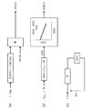
図1は、本実施形態に係るバッテリ充電状態推定装置1(以下、単に充電状態推定装置1という。)の構成を示すブロック図である。該充電状態推定装置1は、車両、特にHEVに搭載されたバッテリBATの充電状態を推定する装置である。該バッテリBATは、例えば鉛蓄電池等の二次電池で構成されており、車体から電気的に絶縁されている。
FIG. 1 is a block diagram illustrating a configuration of a battery charge state estimation device 1 (hereinafter simply referred to as a charge state estimation device 1) according to the present embodiment. The charging
上記充電状態推定装置1は、バッテリBATの充放電電流I及び端子電圧VBATをそれぞれ検出する電流センサ3及び電圧センサ5と、電流積算法によってバッテリBATの充電状態を推定する電流積算法充電状態推定部7(積算法充電状態推定手段)と、OCV法によってバッテリBATの充電状態を推定するOCV法充電状態推定部9(OCV法充電状態推定手段)と、電流積算法充電状態推定部7によって推定されたバッテリBATの充電状態(以下、積算法推定充電状態SOC_Iという。)及びOCV法充電状態推定部9によって推定されたバッテリBATの充電状態(以下、OCV法推定充電状態SOC_Vという。)の平均値である推定充電状態平均値SOC_VIを算出する平均値算出部11(平均値算出手段)と、上記各推定方法の誤差を見積もる誤差見積部13(誤差取得手段)と、該誤差見積部13によって見積もられた誤差に基づいて上記積算法推定充電状態SOC_I、OCV法推定充電状態SOC_V又は推定充電状態平均値SOC_VIを選択し、バッテリBATの充電状態とするマルチプレクサ15と、を備えている。
The charging
上記電流センサ3は、バッテリBATが上述の如く車体から電気的に絶縁されているため、ホール素子タイプのものである。この電流センサ3には、電流積算法充電状態推定部7、OCV法充電状態推定部9及び誤差見積部13が並列に接続され、検出した充放電電流Iを示す信号をこれら各部に送信する。また、上記電圧センサ5には、OCV法充電状態推定部9が接続され、検出した端子電圧を示す信号をOCV法充電状態推定部9に送信する。
The
上記電流積算法充電状態推定部7は、電流センサ3から送信された信号に基づいて積算法推定充電状態SOC_Iを算出する。図2(a)は、電流積算法充電状態推定部7の制御のブロック図である。この電流積算法充電状態推定部7は、電流センサ3によって検出された充放電電流値I及びバッテリBATの既知のバッテリ容量Capに基づいて、バッテリBATの充放電電流の時間積算値ΔSOC_I(ΔSOC_I=∫Idt/Cap)を求める。また、その一方で、電流積算法充電状態推定部7は、バッテリBATの充電状態初期値SOC0を上記OCV法充電状態推定部9から取得する。そして、電流積算法充電状態推定部7は、充電状態初期値SOC0に時間積算値ΔSOC_Iを加算し、バッテリBATの積算法推定充電状態SOC_Iを求めて、マルチプレクサ15に出力する。
The current integration method charging
上記OCV法充電状態推定部9は、電流センサ3及び電圧センサ5から送信された信号に基づいてOCV法推定充電状態SOC_Vを算出する。図2(b)は、OCV法充電状態推定部9の制御のブロック図である。OCV法充電状態推定部9には、予め図2(c)に示すバッテリBATの等価回路モデルが設定されており、この等価回路モデルで設定されたバッテリBATの抵抗値Rと、電流センサ3及び電圧センサ5によってそれぞれ検出された充放電電流値I及び端子電圧値VBATと、に基づいて、バッテリBATの開回路電圧OCV(OCV=VBAT−IR)を算出する。ここで、OCV法充電状態推定部9には、開回路電圧OCVとバッテリBATの充電状態SOCとの対応関係を示すOCV−SOCマップが格納されている。OCV法充電状態推定部9は、このマップを参照して、算出した開回路電圧OCVに対応するバッテリBATのOCV法推定充電状態SOC_Vを取得し、上記マルチプレクサ15に出力する。
The OCV method charging
上記平均値算出部11は、電流積算法充電状態推定部7及びOCV法充電状態推定部9に接続され、これらから積算法推定充電状態SOC_I及びOCV法推定充電状態SOC_Vを取得する。そして、平均値算出部11は、これら推定充電状態SOC_I,SOC_Vの平均値である推定充電状態平均値SOC_VI(SOC_VI=(SOC_V+SOC_I)/2)を算出し、上記マルチプレクサ15に出力する。
The average
上記誤差見積部13は、電流センサ3のオフセット誤差に起因する積算法推定充電状態SOC_Iの誤差のバッテリBATの充放電開始からの時間積算値である積算法充電状態推定誤差SOC_Ierrと、図2(c)に示されたバッテリBATの等価回路モデルに起因するOCV法推定充電状態SOC_Vの誤差のバッテリBATの充放電開始からの時間変化であるOCV法充電状態推定誤差SOC_Verrと、これら両充電状態推定誤差の平均値である誤差平均SOC_VIerrと、を求める。
The
図3(a)は、積算法充電状態推定誤差SOC_Ierrを算出するための制御のブロック図を示す。誤差見積部13は、上記電流センサ3のオフセット誤差に起因する電流誤差Ierrの時間積算値から積算法充電状態推定誤差SOC_Ierr(SOC_Ierr=∫Ierrdt/Cap)を求める。
FIG. 3A shows a block diagram of control for calculating the integration method charging state estimation error SOC_Ierr. The
一方、図3(b)は、OCV法充電状態推定誤差SOC_Verrを算出するための制御のブロック図を示す。誤差見積部13には、予め図3(c)に示すバッテリBATの等価回路モデルが設定されている。この等価回路モデルにおける抵抗は、抵抗真値Rrefと抵抗誤差Rerrとの和で表される一方、充放電電流は、電流真値Irefと電流センサ3のオフセット誤差に起因する電流誤差Ierrとの和で表される。
On the other hand, FIG. 3B shows a block diagram of control for calculating the OCV method charging state estimation error SOC_Verr. In the
この等価回路モデルにおいて、誤差見積部13は、開回路電圧誤差OCVerr(OCVerr={VBAT−(Iref+Ierr)(R+Rerr)}−(VBAT−Iref・R)=−Ierr・Rref+(Iref+Ierr)Rerr)を算出する。なお、Rerrは、正又は負の値を取り得るため、開回路電圧誤差OCVerrは、−Ierr・Rref−(Iref+Ierr)|Rerr|≦開回路誤差OCVerr≦−Ierr・Rref+(Iref+Ierr)|Rerr|の範囲の値を取り得る。ここで、|Rerr|は、Rerrの絶対値である。
In this equivalent circuit model, the
また、誤差見積部13は、上記OCV法充電状態推定部9からOCV法推定充電状態SOC_Vを取得し、上記OCV−SOCマップを参照してOCV法推定充電状態SOC_VにおけるOCVの傾き(dOCV/dSOC)|SOCを求める。そうして、誤差見積部13は、上記開回路電圧誤差OCVerr及び傾き(dOCV/dSOC)|SOCに基づいて、OCV法充電状態推定誤差SOC_Verr(SOC_Verr=(dOCV/dSOC)OCVerr)を算出する。
Further, the
さらに、誤差見積部13は、上記積算法充電状態推定誤差SOC_Ierr及びOCV法充電状態推定誤差SOC_Verrの誤差平均SOC_VIerr(SOC_VIerr=(SOC_Ierr+SOC_Verr)/2)を算出する。
Further, the
そして、誤差見積部13は、算出した積算法充電状態推定誤差SOC_Ierr、OCV法充電状態推定誤差SOC_Verr及び誤差平均SOC_VIerrをマルチプレクサ15に出力する。
Then,
上記マルチプレクサ15は、誤差見積部13からの選択制御入力に基づいて、電流積算法充電状態推定部7、OCV法充電状態推定部9及び平均値算出部11からの入力のうちいずれか1つをバッテリBATの推定充電状態として出力する。具体的には、マルチプレクサ15は、誤差見積部13から入力された積算法充電状態推定誤差SOC_Ierr、OCV法充電状態推定誤差SOC_Verr及び誤差平均SOC_VIerrの大小関係を判別し、最も小さい誤差に対応する方法で推定された充電状態を選択し、選択した推定充電状態をバッテリBATの充電状態として出力する。
The
次に、充電状態推定装置1の動作について図4に示すフローチャートを参照して説明する。
Next, the operation of the charging
バッテリBATの充放電が開始すると、充電状態推定装置1は、バッテリBATの前回の充放電終了時にOCV法充電状態推定部9において推定された推定充電状態前回値SOC(−1)を取得し、OCV法充電状態推定部9のOCV−SOCマップを参照して該推定充電状態前回値SOC(−1)におけるSOCに対するOCVの傾き(dOCV/dSOC)|SOCを算出する(ステップS1)。
When the charging / discharging of the battery BAT starts, the charging
次いで、充電状態推定装置1は、電流センサ3及び電圧センサ5でそれぞれ検出された充放電電流I及び端子電圧VBATに基づいて、開回路電圧誤差OCVerrを演算し、その上限値OCVerrU(OCVerrU=−Ierr・Rref+(Iref+Ierr)|Rerr|)及び下限値OCVerrL(OCVerrL=−Ierr・Rref−(Iref+Ierr)|Rerr|)を算出する(ステップS3)。なお、この際、電流センサ3のオフセット誤差に起因する電流誤差IerrをIerr>0と仮定する。
Next, the charging
続いて、充電状態推定装置1は、ステップS1で算出されたSOC(−1)に対するOCVの傾き(dOCV/dSOC)|SOCと、ステップS3で算出された開回路電圧誤差OCVerrとに基づいて、OCV法充電状態推定誤差SOC_Verrを算出する(ステップS5)。
Subsequently, the state-of-
その一方で、充電状態推定装置1は、ステップS3で算出された開回路電圧誤差OCVerrの上限値OCVerrUが0よりも小さいか否かを判別する(ステップS7)。
On the other hand, the charging
バッテリBATの充放電電流Iが比較的大きい場合、バッテリBATの充電率が比較的小さい場合、または、これら双方の条件が成立する場合には、開回路電圧誤差OCVerrの上限値OCVerrUが0以上となる可能性が高い(ステップS7でNO)。この場合、充電状態推定装置1は、誤差平均SOC_VIerrを選択せず、積算法充電状態推定誤差SOC_Ierrの絶対値|SOC_Ierr|がOCV法充電状態推定誤差SOC_Verrの下限値OCVerrLの絶対値|OCVerrL|よりも小さいか否かを判別する(ステップS9)。
When the charging / discharging current I of the battery BAT is relatively large, when the charging rate of the battery BAT is relatively small, or when both of these conditions are satisfied, the upper limit value OCVerrU of the open circuit voltage error OCVerr is 0 or more. (NO in step S7). In this case, the charging
積算法充電状態推定誤差SOC_Ierrの絶対値|SOC_Ierr|がOCV法充電状態推定誤差SOC_Verrの下限値OCVerrLの絶対値|OCVerrL|よりも小さい場合(ステップS9でYES)には、図5(a)に示すように、破線で示す積算法充電状態推定誤差SOC_Ierrが最も小さいため、充電状態推定装置1は、バッテリBATの充電状態として積算法推定充電状態SOC_Iを選択し(ステップS11)、この積算法推定充電状態SOC_IをバッテリBATの充電状態として出力し、処理をステップS1に戻す。
When the absolute value | SOC_Ierr | of the integration method charging state estimation error SOC_Ierr is smaller than the absolute value | OCVerrL | of the lower limit value OCVerrL | of the OCV charging state estimation error SOC_Verr (YES in step S9), FIG. As shown, since the integration method charging state estimation error SOC_Ierr indicated by the broken line is the smallest, the charging
一方、積算法充電状態推定誤差SOC_Ierrの絶対値|SOC_Ierr|がOCV法充電状態推定誤差SOC_Verrの下限値OCVerrLの絶対値|OCVerrL|よりも大きい場合(ステップS9でNO)には、OCV法充電状態推定誤差SOC_Vが最も小さいため、充電状態推定装置1は、バッテリBATの充電状態としてOCV法推定充電状態SOC_Vを選択し(ステップS13)、このOCV法推定充電状態SOC_VをバッテリBATの充電状態として出力する。そして、充電状態推定装置1は、積算法充電状態推定誤差SOC_Ierrを0とし、電流積算法による誤差をリセットし(ステップS15)、処理をステップS1に戻す。
On the other hand, when the absolute value | SOC_Ierr | of the integration method charging state estimation error SOC_Ierr is larger than the absolute value | OCVerrL | of the lower limit value OCVerrL | of the OCV method charging state estimation error SOC_Verr (NO in step S9), the OCV method charging state Since the estimation error SOC_V is the smallest, the charging
また、ステップS7において、バッテリBATの充放電電流Iが比較的小さい場合、バッテリBATの充電率が比較的大きい場合、または、これら双方の条件が成立する場合には、開回路電圧誤差OCVerrの上限値OCVerrUが0よりも小さくなる可能性が高い(ステップS7でYES)。この場合、充電状態推定装置1は、図5(b)に示すように、一点鎖線で示すOCV法充電状態推定誤差SOC_Verrが比較的小さくなり、誤差平均SOC_VIerrが最も小さくなるため、推定充電状態平均値SOC_VIを選択し(ステップS17)、この推定充電状態平均値SOC_VIをバッテリBATの充電状態として出力する(ステップS19)。そして、充電状態推定装置1は、処理をステップS1に戻す。
In step S7, when the charging / discharging current I of the battery BAT is relatively small, the charging rate of the battery BAT is relatively large, or both of these conditions are satisfied, the upper limit of the open circuit voltage error OCVerr There is a high possibility that the value OCVerrU is smaller than 0 (YES in step S7). In this case, as shown in FIG. 5 (b), the charging
図6は、バッテリBATの各方法における充電状態推定誤差の時間推移の一例を示す図である。である。図6において、縦軸は誤差の大きさを示し、横軸はバッテリBATの充放電開始からの経過時間tを示している。この例では、OCV法充電状態推定誤差SOC_Verrの上限値SOCerrUが0より大きい場合を示している。なお、図6において、積算法充電状態推定誤差SOC_Ierrを破線で示し、OCV法充電状態推定誤差SOC_Verrを破線で示し、誤差平均SOC_VIerrを破線で示している。 FIG. 6 is a diagram illustrating an example of a time transition of a charging state estimation error in each method of the battery BAT. It is. In FIG. 6, the vertical axis indicates the magnitude of the error, and the horizontal axis indicates the elapsed time t from the start of charging / discharging of the battery BAT. In this example, the upper limit SOCerrU of the OCV method charging state estimation error SOC_Verr is greater than zero. In FIG. 6, the integration method charging state estimation error SOC_Ierr is indicated by a broken line, the OCV method charging state estimation error SOC_Verr is indicated by a broken line, and the error average SOC_VIerr is indicated by a broken line.
バッテリBATが充放電を開始すると、充電状態推定装置1は、積算法充電状態推定誤差SOC_Ierrが最も小さいため、積算法推定充電状態SOC_Iを選択し、バッテリBATの充電状態とする。
When the battery BAT starts charging and discharging, the charging
電流センサのオフセット誤差に起因する誤差が時間積算されると、積算法充電状態推定誤差SOC_Ierrが次第に大きくなり、経過時間t1で積算法充電状態推定誤差SOC_Ierrが誤差平均SOC_VIerrよりも大きくなり、当該誤差平均SOC_VIerrが最も小さくなる。したがって、充電状態推定装置1は、推定充電状態平均値SOC_VIを選択し、バッテリBATの充電状態とする。
When the error due to the offset error of the current sensor is integrated over time, the integration method charging state estimation error SOC_Ierr gradually increases, and at the elapsed time t1, the integration method charging state estimation error SOC_Ierr becomes larger than the error average SOC_VIerr. The average SOC_VIerr is the smallest. Therefore, the charging
経過時間t2になると、誤差平均SOC_VIerrが積算法充電状態推定誤差SOC_Ierrよりも大きくなり、当該積算法充電状態推定誤差SOC_Ierrが最も小さくなる。したがって、充電状態推定装置1は、積算法推定充電状態SOC_Iを選択し、バッテリBATの充電状態とする。
When the elapsed time t2 is reached, the error average SOC_VIerr becomes larger than the integration method charging state estimation error SOC_Ierr, and the integration method charging state estimation error SOC_Ierr becomes the smallest. Therefore, the charging
経過時間t3になると、再び積算法充電状態推定誤差SOC_Ierrが誤差平均SOC_VIerrよりも大きくなり、当該誤差平均SOC_VIerrが最も小さくなる。したがって、充電状態推定装置1は、推定充電状態平均値SOC_VIを選択し、バッテリBATの充電状態とする。
When the elapsed time t3 is reached, the integration method charging state estimation error SOC_Ierr again becomes larger than the error average SOC_VIerr, and the error average SOC_VIerr becomes the smallest. Therefore, the charging
そして、経過時間t4になると、積算法充電状態推定誤差SOC_Ierrが大きくなり、誤差平均SOC_VIerrがOCV法充電状態推定誤差SOC_Verrよりも大きくなる。このタイミングで、充電状態推定装置1は、OCV法充電状態推定誤差SOC_Verrが最も小さくなるため、OCV法推定充電状態SOC_Vを選択し、バッテリBATの充電状態とする。それと同時に、充電状態推定装置1は、積算法充電状態推定誤差SOC_Ierrを0にし、リセットする。
Then, at the elapsed time t4, the integration method charging state estimation error SOC_Ierr increases, and the error average SOC_VIerr becomes larger than the OCV method charging state estimation error SOC_Verr. At this timing, since the OCV method charging state estimation error SOC_Verr is the smallest, the charging
充電状態推定装置1は、バッテリBATが充放電をしている間、上記の処理を繰り返す。
The charging
このように、充電状態推定装置1は、バッテリBATの充放電開始からの積算法充電状態推定誤差SOC_Ierr、OCV法充電状態推定誤差SOC_Verr及びこれらの誤差平均SOC_VIerrの時間推移を常時モニタし、最も小さい誤差に対応する方法で推定された充電状態を選択することにより、精度良い充電状態の推定が可能となる。
As described above, the charging
−発明の実施形態の効果−
上記実施形態によれば、電流積算法及びOCV法でバッテリBATの充電状態を推定すると共に、両方法における誤差のバッテリ充放電開始からの時間変化を求めている。電流積算法における誤差の時間変化を求める際には、支配的な要因である電流センサに起因する積算法充電状態推定誤差SOC_Ierrの時間変化を求める。一方、OCV法における誤差の時間変化を求める際には、主要因であるバッテリBATの等価回路モデルに起因する誤差の時間変化を求める。そのため、各推定方法における誤差の時間変化を精度良く求めることができる。そして、求められた誤差の時間変化のうち小さい方の推定方法による推定充電状態を選択し、バッテリBATの充電状態とする。このように、各推定方法による誤差の時間変化を精度良く求めると共に、誤差の小さい推定方法による推定充電状態を選択してバッテリBATの充電状態としているので、従来よりも精度良くバッテリBATの充電状態を推定することができる。
-Effects of the embodiment of the invention-
According to the above embodiment, the state of charge of the battery BAT is estimated by the current integration method and the OCV method, and the time change from the start of battery charge / discharge in both methods is obtained. When obtaining the time change of the error in the current integration method, the time change of the integration method charging state estimation error SOC_Ierr caused by the current sensor, which is a dominant factor, is obtained. On the other hand, when obtaining the time variation of the error in the OCV method, the time variation of the error due to the equivalent circuit model of the battery BAT, which is the main factor, is obtained. Therefore, it is possible to accurately obtain the time change of the error in each estimation method. Then, the estimated charging state by the smaller estimation method among the obtained time variations of the error is selected, and the charging state of the battery BAT is set. In this way, the time variation of the error by each estimation method is obtained with high accuracy, and the estimated charge state by the estimation method with a small error is selected as the charge state of the battery BAT. Therefore, the charge state of the battery BAT is more accurate than before. Can be estimated.
ここで、バッテリBATの充放電電流が比較的小さい場合、バッテリBATの充放電開始からの時間経過によっては、積算法充電状態推定誤差SOC_IerrやOCV法充電状態推定誤差SOC_Verrよりも、これらの平均である誤差平均SOC_VIerrが最も小さくなることがある。 Here, when the charging / discharging current of the battery BAT is relatively small, depending on the time elapsed from the start of charging / discharging of the battery BAT, the average of these values may be greater than the integration method charging state estimation error SOC_Ierr and the OCV method charging state estimation error SOC_Verr A certain error average SOC_VIerr may be the smallest.
そこで、上記実施形態によれば、電流積算法及びOCV法のほかに、両方法で推定された充電状態の平均値である推定充電状態平均値SOC_VIerrを求め、さらに、積算法充電状態推定誤差SOC_Ierr及びOCV法充電状態推定誤差SOC_Verrの、これらの平均である誤差平均SOC_VIerrを求める。そして、これら3つの誤差の時間変化のうち最も小さい誤差の方法による推定充電状態を選択する。したがって、より一層精度良くバッテリの充電状態を推定することができる。 Therefore, according to the above embodiment, in addition to the current integration method and the OCV method, an estimated charge state average value SOC_VIerr that is an average value of the charge state estimated by both methods is obtained, and further, the integration method charge state estimation error SOC_Ierr Then, an error average SOC_VIerr, which is an average of the SOCV method charging state estimation error SOC_Verr, is obtained. Then, an estimated charge state is selected by the method of the smallest error among these three error time variations. Therefore, the state of charge of the battery can be estimated with higher accuracy.
また、上記実施形態によれば、バッテリBATの充放電開始からの経過時間tに基づいて推定充電状態を選択しているので、簡易且つ比較的精度良くバッテリBATの充電状態を推定することができる。 Moreover, according to the said embodiment, since the estimated charge state is selected based on the elapsed time t from the start of charging / discharging of the battery BAT, the charge state of the battery BAT can be estimated easily and with relatively high accuracy. .
さらに、上記実施形態によれば、積算法充電状態推定誤差SOC_Ierrは、電流センサ3のオフセット誤差が時間積算されたものである。つまり、バッテリBATの充放電開始段階では、積算法充電状態推定誤差SOC_Ierrが最も小さい。そのため、バッテリBATの充放電開始から所定時間経過までは、最も誤差の小さい電流積算法による推定充電状態SOC_Iを選択することにより、バッテリBATの充電状態をより精度良く推定することができる。
Further, according to the embodiment, the integration method charging state estimation error SOC_Ierr is obtained by integrating the offset error of the
(参考例)
図7は、上記実施形態の変形例に係るバッテリ充電状態推定装置2の構成を示すブロック図である。この充電状態推定装置2は、平均値算出部11を備えない点で上記実施形態に係る充電状態推定装置1と異なる。そして、当該充電状態推定装置2は、誤差見積部13において積算法充電状態推定誤差SOC_Ierr及びOCV法充電状態推定誤差SOC_Verrを見積もり、マルチプレクサ15において小さい方の誤差に対応する推定方法で推定された充電状態をバッテリBATの充電状態とする。
( Reference example )
FIG. 7 is a block diagram showing a configuration of the battery charge
これにより、構成を簡素としながらも、電流積算法又はOCV法のみによるバッテリBATの充電状態推定よりも精度良く推定を行うことができる。 Thus, while simplifying the configuration, it is possible to perform estimation with higher accuracy than estimation of the state of charge of the battery BAT using only the current integration method or the OCV method.
(その他の実施形態)
なお、上記実施形態では、積算法充電状態推定誤差SOC_Ierr、OCV法充電状態推定誤差SOC_Verr及び誤差平均SOC_VIerrに基づいて積算法推定充電状態SOC_I、OCV法推定充電状態SOC_V又は推定状態平均値SOC_VIを選択しているが、これに限定されず、バッテリBATの充放電開始からの経過時間tに基づいて選択してもよい。この場合、経過時間にのみ基づいて選択するので、制御を簡素にすることができる。
(Other embodiments)
In the above embodiment, the integration method estimated charge state SOC_I, the OCV method estimated charge state SOC_V, or the estimated state average value SOC_VI is selected based on the integration method charge state estimation error SOC_Ierr, the OCV method charge state estimation error SOC_Verr, and the error average SOC_VIerr. However, the present invention is not limited to this, and the selection may be made based on the elapsed time t from the start of charging / discharging of the battery BAT. In this case, since the selection is made based only on the elapsed time, the control can be simplified.
以上説明したように、本発明に係るバッテリ充電状態推定方法及びバッテリ充電状態推定装置は、バッテリの充電状態をより精度良く推定する用途に適用することができる。 As described above, the battery charge state estimation method and the battery charge state estimation device according to the present invention can be applied to a use for estimating the charge state of the battery with higher accuracy.
1 充電状態推定装置(バッテリ充電状態推定装置)
3 電流センサ
5 電圧センサ
7 電流積算法充電状態推定部(積算法充電状態推定手段)
9 OCV法充電状態推定部(OCV法充電状態推定手段)
11 平均値算出部(平均値算出手段)
13 誤差見積部(誤差取得手段)
15 マルチプレクサ(充電状態選択手段)
BAT バッテリ
1 Charge state estimation device (battery charge state estimation device)
3
9 OCV method charge state estimation unit (OCV method charge state estimation means)
11 Average value calculation unit (average value calculation means)
13 Error estimation part (error acquisition means)
15 Multiplexer (charging state selection means)
BAT battery
Claims (4)
電流センサによって検出された上記バッテリの充放電電流を時間積算し、この時間積算値に基づいて上記バッテリの充電状態である積算法推定充電状態を推定する積算法充電状態推定工程と、
電圧センサによって検出された上記バッテリの端子電圧と上記電流センサによって検出された充放電電流と上記バッテリの等価回路モデルとに基づいて該バッテリの開回路電圧を求め、該開回路電圧から上記バッテリの充電状態であるOCV法推定充電状態を推定するOCV法充電状態推定工程と、
上記積算法推定充電状態及びOCV法推定充電状態の平均値である推定充電状態平均値を求める平均値取得工程と、
上記電流センサに起因する上記積算法推定充電状態の誤差の上記バッテリの充放電開始からの時間積算値である積算法誤差、上記等価回路モデルに起因する上記OCV法推定充電状態の誤差の上記バッテリの充放電開始からの時間変化であるOCV法誤差、並びに、上記積算法誤差及びOCV法誤差の平均値の時間変化である誤差平均を求める誤差取得工程と、
該誤差取得工程において求められた上記積算法誤差、OCV法誤差及び誤差平均に基づいて上記積算法推定充電状態、OCV法推定充電状態又は推定充電状態平均値を選択し、選択した推定充電状態を上記バッテリの充電状態とする充電状態選択工程と、を備えることを特徴とするバッテリ充電状態推定方法。 A battery charge state estimation method for estimating a charge state of the battery based on a charge / discharge current and a terminal voltage of the battery,
An integration method charging state estimation step of integrating the charging / discharging current of the battery detected by a current sensor over time, and estimating an integration method estimation charging state that is a charging state of the battery based on the time integration value;
An open circuit voltage of the battery is obtained based on a terminal voltage of the battery detected by the voltage sensor, a charge / discharge current detected by the current sensor, and an equivalent circuit model of the battery, and the battery's open circuit voltage is determined from the open circuit voltage. OCV method charge state estimation step of estimating the charge state of the OCV method estimated charge state;
An average value obtaining step for obtaining an estimated charge state average value which is an average value of the integration method estimated charge state and the OCV method estimated charge state;
The cumulative method estimated time integrated value in the form of the integration method error from charging and discharging the start of the battery error in a charged state, the upper Symbol error of the of the OCV method estimated charge state resulting from the equivalent circuit model due to said current sensor An error obtaining step of obtaining an OCV method error that is a time change from the start of charge / discharge of the battery, and an error average that is a time change of an average value of the integration method error and the OCV method error ;
Based on the integration method error , OCV method error and error average obtained in the error acquisition step, the integration method estimated charge state , OCV method estimated charge state or estimated charge state average value is selected, and the selected estimated charge is selected. And a charging state selection step for setting the state of the battery to a charging state of the battery.
上記充電状態選択工程において、上記バッテリの充放電開始からの経過時間に基づいて選択することを特徴とするバッテリ充電状態推定方法。 The battery charge state estimation method according to claim 1 ,
In the charging state selection step, the battery charging state estimation method is selected based on an elapsed time from the start of charging / discharging of the battery.
上記充電状態選択工程において、上記バッテリの充放電開始から所定時間経過までの間、上記積算法推定充電状態を選択することを特徴とするバッテリ充電状態推定方法。 The battery charge state estimation method according to claim 1 or 2 ,
In the charge state selection step, the battery charge state estimation method is characterized in that the integration method estimated charge state is selected from the start of charging / discharging of the battery to a lapse of a predetermined time.
上記バッテリの充放電電流を検出する電流センサと、
上記バッテリの端子電圧を検出する電圧センサと、
上記電流センサによって検出された充放電電流を時間積算し、この時間積算値に基づいて上記バッテリの充電状態である積算法推定充電状態を推定する積算法充電状態推定手段と、
上記電圧センサによって検出された端子電圧と上記電流センサによって検出された充放電電流と上記バッテリの等価回路モデルとに基づいて開回路電圧を求め、該開回路電圧から上記バッテリの充電状態であるOCV法推定充電状態を推定するOCV法充電状態推定手段と、
上記積算法推定充電状態及びOCV法推定充電状態の平均値である推定充電状態平均値を求める平均値算出手段と、
上記電流センサに起因する上記積算法推定充電状態の誤差の上記バッテリの充放電開始からの時間積算値である積算法誤差、上記等価回路モデルに起因する上記OCV法推定充電状態の誤差の上記バッテリの充放電開始からの時間変化であるOCV法誤差、並びに、上記積算法誤差及びOCV法誤差の平均値の時間変化である誤差平均を求める誤差取得手段と、
該誤差取得手段によって求められた上記積算法誤差、OCV法誤差及び誤差平均に基づいて上記積算法推定充電状態、OCV法推定充電状態又は推定充電状態平均値を選択し、選択した推定充電状態を上記バッテリの充電状態とする充電状態選択手段と、を備えることを特徴とするバッテリ充電状態推定装置。 A battery charge state estimation device for estimating a charge state of a battery based on a terminal voltage and a charge / discharge current of the battery,
A current sensor for detecting the charge / discharge current of the battery;
A voltage sensor for detecting the terminal voltage of the battery;
Integration method charging state estimation means for integrating the charging / discharging current detected by the current sensor over time, and estimating the integration method estimation charging state that is the charging state of the battery based on the time integration value;
An open circuit voltage is obtained based on the terminal voltage detected by the voltage sensor, the charge / discharge current detected by the current sensor, and the equivalent circuit model of the battery, and the OCV that is the state of charge of the battery is determined from the open circuit voltage. OCV method charging state estimating means for estimating the method estimating charging state;
Average value calculating means for obtaining an estimated charge state average value that is an average value of the integration method estimated charge state and the OCV method estimated charge state;
The cumulative method estimated time integrated value in the form of the integration method error from charging and discharging the start of the battery error in a charged state, the upper Symbol error of the of the OCV method estimated charge state resulting from the equivalent circuit model due to said current sensor An error acquisition means for obtaining an OCV method error that is a time change from the start of charge / discharge of the battery, and an error average that is a time change of an average value of the integration method error and the OCV method error ;
Based on the integration method error , OCV method error and error average obtained by the error acquisition means, the integration method estimated charge state , OCV method estimated charge state or estimated charge state average value is selected, and the selected estimated charge state is A battery charge state estimation device comprising: a charge state selection unit configured to charge the battery.
Priority Applications (1)
| Application Number | Priority Date | Filing Date | Title |
|---|---|---|---|
| JP2014114130A JP6201899B2 (en) | 2014-06-02 | 2014-06-02 | Battery charge state estimation method and battery charge state estimation device |
Applications Claiming Priority (1)
| Application Number | Priority Date | Filing Date | Title |
|---|---|---|---|
| JP2014114130A JP6201899B2 (en) | 2014-06-02 | 2014-06-02 | Battery charge state estimation method and battery charge state estimation device |
Publications (2)
| Publication Number | Publication Date |
|---|---|
| JP2015227840A JP2015227840A (en) | 2015-12-17 |
| JP6201899B2 true JP6201899B2 (en) | 2017-09-27 |
Family
ID=54885384
Family Applications (1)
| Application Number | Title | Priority Date | Filing Date |
|---|---|---|---|
| JP2014114130A Active JP6201899B2 (en) | 2014-06-02 | 2014-06-02 | Battery charge state estimation method and battery charge state estimation device |
Country Status (1)
| Country | Link |
|---|---|
| JP (1) | JP6201899B2 (en) |
Cited By (1)
| Publication number | Priority date | Publication date | Assignee | Title |
|---|---|---|---|---|
| US11480620B2 (en) | 2017-12-21 | 2022-10-25 | Lg Energy Solution, Ltd. | Method for calibrating state of charge of battery and battery management system |
Families Citing this family (3)
| Publication number | Priority date | Publication date | Assignee | Title |
|---|---|---|---|---|
| CN107546433B (en) * | 2017-09-01 | 2019-08-23 | 华霆(合肥)动力技术有限公司 | Battery information processing method and processing device |
| JP7172145B2 (en) * | 2018-06-01 | 2022-11-16 | マツダ株式会社 | Battery capacity estimation device and battery capacity estimation method |
| CN112034366B (en) * | 2020-08-25 | 2023-07-14 | 惠州市蓝微电子有限公司 | SOC dynamic compensation method and electronic system |
Family Cites Families (6)
| Publication number | Priority date | Publication date | Assignee | Title |
|---|---|---|---|---|
| JP3767150B2 (en) * | 1998-01-09 | 2006-04-19 | 日産自動車株式会社 | Battery remaining capacity detection device |
| JP4071207B2 (en) * | 2004-03-12 | 2008-04-02 | 株式会社日本自動車部品総合研究所 | Battery current measuring device |
| JP4670256B2 (en) * | 2004-05-14 | 2011-04-13 | 新神戸電機株式会社 | Battery status detection method |
| JP2011106952A (en) * | 2009-11-17 | 2011-06-02 | Honda Motor Co Ltd | Method for estimating residual capacity of battery |
| JP5490215B2 (en) * | 2010-02-24 | 2014-05-14 | 三菱重工業株式会社 | Charging rate calculation system |
| JP5640477B2 (en) * | 2010-06-08 | 2014-12-17 | マツダ株式会社 | Battery remaining capacity detection method and detection apparatus |
-
2014
- 2014-06-02 JP JP2014114130A patent/JP6201899B2/en active Active
Cited By (1)
| Publication number | Priority date | Publication date | Assignee | Title |
|---|---|---|---|---|
| US11480620B2 (en) | 2017-12-21 | 2022-10-25 | Lg Energy Solution, Ltd. | Method for calibrating state of charge of battery and battery management system |
Also Published As
| Publication number | Publication date |
|---|---|
| JP2015227840A (en) | 2015-12-17 |
Similar Documents
| Publication | Publication Date | Title |
|---|---|---|
| JP6844683B2 (en) | Power storage element management device, SOC reset method, power storage element module, power storage element management program and mobile | |
| JP6607255B2 (en) | Battery degradation degree estimation apparatus and estimation method | |
| CN107533109B (en) | Battery control device and electric vehicle system | |
| KR100996693B1 (en) | Charged state estimating device and charged state estimating method of secondary battery | |
| JP5051661B2 (en) | Method and apparatus for estimating SOC value of secondary battery, and degradation determination method and apparatus | |
| KR102080632B1 (en) | Battery management system and its operating method | |
| US10209317B2 (en) | Battery control device for calculating battery deterioration based on internal resistance increase rate | |
| US10359474B2 (en) | Charge state calculation device and charge state calculation method | |
| JP6714838B2 (en) | State estimation device and state estimation method | |
| KR102337489B1 (en) | System for estimating state of health of battery of electric vehicle | |
| KR102004404B1 (en) | Assessment of the energy that can be extracted from a motor vehicle battery | |
| JP5784108B2 (en) | Charge control device | |
| WO2014147899A1 (en) | Method for estimating fully-charged power capacity, and device | |
| JP6449609B2 (en) | Secondary battery charging rate estimation method and charging rate estimation device | |
| JP6439352B2 (en) | Secondary battery deterioration state estimation device | |
| JPWO2008026477A1 (en) | Method and apparatus for estimating SOC value of secondary battery, and degradation determination method and apparatus | |
| KR102274383B1 (en) | Assessing the quantity of energy in a motor vehicle battery | |
| KR20150019190A (en) | Method of Estimating Battery Stste-Of-Charge and Apparatus therefor the same | |
| JP6128014B2 (en) | Vehicle charging control device | |
| JP6201899B2 (en) | Battery charge state estimation method and battery charge state estimation device | |
| JP2012057956A (en) | Deterioration degree estimation apparatus for battery | |
| TWI613454B (en) | Full charge capacity (fcc) calibration method | |
| KR102441800B1 (en) | Method and apparatus for estimating state of health of battery | |
| JP6452403B2 (en) | Secondary battery state detection device and secondary battery state detection method | |
| US20070170892A1 (en) | Method and apparatus for estimating remaining capacity of electric storage |
Legal Events
| Date | Code | Title | Description |
|---|---|---|---|
| A621 | Written request for application examination |
Free format text: JAPANESE INTERMEDIATE CODE: A621 Effective date: 20160323 |
|
| A977 | Report on retrieval |
Free format text: JAPANESE INTERMEDIATE CODE: A971007 Effective date: 20170125 |
|
| A131 | Notification of reasons for refusal |
Free format text: JAPANESE INTERMEDIATE CODE: A131 Effective date: 20170207 |
|
| A521 | Written amendment |
Free format text: JAPANESE INTERMEDIATE CODE: A523 Effective date: 20170227 |
|
| TRDD | Decision of grant or rejection written | ||
| A01 | Written decision to grant a patent or to grant a registration (utility model) |
Free format text: JAPANESE INTERMEDIATE CODE: A01 Effective date: 20170801 |
|
| A61 | First payment of annual fees (during grant procedure) |
Free format text: JAPANESE INTERMEDIATE CODE: A61 Effective date: 20170814 |
|
| R150 | Certificate of patent or registration of utility model |
Ref document number: 6201899 Country of ref document: JP Free format text: JAPANESE INTERMEDIATE CODE: R150 |