JP6200475B2 - System and method for electrochemical reduction of carbon dioxide - Google Patents
System and method for electrochemical reduction of carbon dioxide Download PDFInfo
- Publication number
- JP6200475B2 JP6200475B2 JP2015208816A JP2015208816A JP6200475B2 JP 6200475 B2 JP6200475 B2 JP 6200475B2 JP 2015208816 A JP2015208816 A JP 2015208816A JP 2015208816 A JP2015208816 A JP 2015208816A JP 6200475 B2 JP6200475 B2 JP 6200475B2
- Authority
- JP
- Japan
- Prior art keywords
- cathode
- carbon dioxide
- anode
- chamber
- catholyte
- Prior art date
- Legal status (The legal status is an assumption and is not a legal conclusion. Google has not performed a legal analysis and makes no representation as to the accuracy of the status listed.)
- Active
Links
Images


Classifications
-
- C—CHEMISTRY; METALLURGY
- C25—ELECTROLYTIC OR ELECTROPHORETIC PROCESSES; APPARATUS THEREFOR
- C25B—ELECTROLYTIC OR ELECTROPHORETIC PROCESSES FOR THE PRODUCTION OF COMPOUNDS OR NON-METALS; APPARATUS THEREFOR
- C25B11/00—Electrodes; Manufacture thereof not otherwise provided for
- C25B11/04—Electrodes; Manufacture thereof not otherwise provided for characterised by the material
- C25B11/051—Electrodes formed of electrocatalysts on a substrate or carrier
-
- C—CHEMISTRY; METALLURGY
- C25—ELECTROLYTIC OR ELECTROPHORETIC PROCESSES; APPARATUS THEREFOR
- C25B—ELECTROLYTIC OR ELECTROPHORETIC PROCESSES FOR THE PRODUCTION OF COMPOUNDS OR NON-METALS; APPARATUS THEREFOR
- C25B1/00—Electrolytic production of inorganic compounds or non-metals
-
- C—CHEMISTRY; METALLURGY
- C25—ELECTROLYTIC OR ELECTROPHORETIC PROCESSES; APPARATUS THEREFOR
- C25B—ELECTROLYTIC OR ELECTROPHORETIC PROCESSES FOR THE PRODUCTION OF COMPOUNDS OR NON-METALS; APPARATUS THEREFOR
- C25B11/00—Electrodes; Manufacture thereof not otherwise provided for
- C25B11/04—Electrodes; Manufacture thereof not otherwise provided for characterised by the material
- C25B11/051—Electrodes formed of electrocatalysts on a substrate or carrier
- C25B11/055—Electrodes formed of electrocatalysts on a substrate or carrier characterised by the substrate or carrier material
- C25B11/057—Electrodes formed of electrocatalysts on a substrate or carrier characterised by the substrate or carrier material consisting of a single element or compound
-
- C—CHEMISTRY; METALLURGY
- C25—ELECTROLYTIC OR ELECTROPHORETIC PROCESSES; APPARATUS THEREFOR
- C25B—ELECTROLYTIC OR ELECTROPHORETIC PROCESSES FOR THE PRODUCTION OF COMPOUNDS OR NON-METALS; APPARATUS THEREFOR
- C25B11/00—Electrodes; Manufacture thereof not otherwise provided for
- C25B11/04—Electrodes; Manufacture thereof not otherwise provided for characterised by the material
- C25B11/051—Electrodes formed of electrocatalysts on a substrate or carrier
- C25B11/073—Electrodes formed of electrocatalysts on a substrate or carrier characterised by the electrocatalyst material
- C25B11/075—Electrodes formed of electrocatalysts on a substrate or carrier characterised by the electrocatalyst material consisting of a single catalytic element or catalytic compound
- C25B11/081—Electrodes formed of electrocatalysts on a substrate or carrier characterised by the electrocatalyst material consisting of a single catalytic element or catalytic compound the element being a noble metal
-
- Y—GENERAL TAGGING OF NEW TECHNOLOGICAL DEVELOPMENTS; GENERAL TAGGING OF CROSS-SECTIONAL TECHNOLOGIES SPANNING OVER SEVERAL SECTIONS OF THE IPC; TECHNICAL SUBJECTS COVERED BY FORMER USPC CROSS-REFERENCE ART COLLECTIONS [XRACs] AND DIGESTS
- Y02—TECHNOLOGIES OR APPLICATIONS FOR MITIGATION OR ADAPTATION AGAINST CLIMATE CHANGE
- Y02E—REDUCTION OF GREENHOUSE GAS [GHG] EMISSIONS, RELATED TO ENERGY GENERATION, TRANSMISSION OR DISTRIBUTION
- Y02E60/00—Enabling technologies; Technologies with a potential or indirect contribution to GHG emissions mitigation
- Y02E60/30—Hydrogen technology
- Y02E60/36—Hydrogen production from non-carbon containing sources, e.g. by water electrolysis
Description
この発明は、一般に、二酸化炭素の選択的および効率的な電気化学的還元のためのシステムおよび方法に関する。 The present invention generally relates to systems and methods for selective and efficient electrochemical reduction of carbon dioxide.
背景
産業処理によって地球の大気中に放出される二酸化炭素の量を低減することは、大きな環境的および経済的意義のある技術的な挑戦である。結果的に産業生産および経済活動を減ずることなく、大気中の二酸化炭素生成において大きな低減を達成できることは、非常に有益であろう。
Background Reducing the amount of carbon dioxide released into the Earth's atmosphere by industrial processing is a major environmental and economic technical challenge. It would be very beneficial to be able to achieve a significant reduction in atmospheric carbon dioxide production without reducing industrial production and economic activity as a result.
これらの目的を達成するための1つの考えられ得るアプローチは、燃焼反応によって生じた二酸化炭素の電気化学的還元を通したものである。そのようなアプローチは炭素の生成を低減するので、これは、以前においては温室効果ガス排出であったものから利用可能な燃料を生成するというさらなる利益を有することができる。たとえば、水性環境における二酸化炭素の電気化学的還元は、正しい条件下では、合成ガスとして公知である一酸化炭素と水素ガスとの混合物を生成し得る。そのような合成ガスは、次いで、公知の方法によって、さまざまな利用可能な燃料に処理され得る。 One possible approach to achieving these goals is through the electrochemical reduction of carbon dioxide produced by the combustion reaction. Since such an approach reduces carbon production, this can have the added benefit of producing usable fuel from what was previously greenhouse gas emissions. For example, electrochemical reduction of carbon dioxide in an aqueous environment can produce a mixture of carbon monoxide and hydrogen gas, known as synthesis gas, under the correct conditions. Such syngas can then be processed into various available fuels by known methods.
いくつかの金属が、二酸化炭素の電気化学的還元のための考えられ得る電気触媒として試験されてきた。金は、かなりの電流密度を運び得、二酸化炭素の一酸化炭素への還元を、相対的に低い電位で、高い選択性を持って行ない得る。しかしながら、金は、その低い埋蔵量および高いコストのため、大規模な適用例に対しては好ましくない。銅は、一酸化炭素生成に関して低い選択性を呈し、金によって達成される電流密度に匹敵する電流密度を達成するのに、より大きな電位を必要とする。 Several metals have been tested as possible electrocatalysts for the electrochemical reduction of carbon dioxide. Gold can carry significant current density and can reduce carbon dioxide to carbon monoxide with high selectivity at relatively low potentials. However, gold is not preferred for large scale applications due to its low reserves and high cost. Copper exhibits a low selectivity for carbon monoxide production and requires a larger potential to achieve a current density comparable to that achieved by gold.
銀系の電気触媒は二酸化炭素の一酸化炭素への還元を選択的に促進し得、金と比較してかなり安価である。しかしながら、これまで用いられてきた一般的な多結晶の銀電極は、二酸化炭素還元に対して大きな過電位を必要とし、低い過電位で低い一酸化炭素選択性を示し、銀を、二酸化炭素還元のための電気触媒としては、現時点では実用的ではない選択肢にする。二酸化炭素の一酸化炭素への電気化学的還元のための触媒として銀の効率性および選択性を改善するシステムおよび方法は有益であろう。 Silver-based electrocatalysts can selectively promote the reduction of carbon dioxide to carbon monoxide and are considerably less expensive than gold. However, the general polycrystalline silver electrode used so far requires a large overpotential for carbon dioxide reduction, exhibits low carbon monoxide selectivity at a low overpotential, and reduces silver to carbon dioxide reduction. For electrocatalysts, make it an unpractical option at the moment. Systems and methods that improve the efficiency and selectivity of silver as a catalyst for electrochemical reduction of carbon dioxide to carbon monoxide would be beneficial.
概要
二酸化炭素の一酸化炭素への電気化学的還元のためのシステムおよび方法が提供される。
SUMMARY Systems and methods for electrochemical reduction of carbon dioxide to carbon monoxide are provided.
1つの実現例においては、二酸化炭素の電気化学的還元のためのシステムが開示される。このシステムは、カソード液と、カソード液と接触する陽極酸化処理された銀を含有するカソードとを有するカソードチャンバを含む。このシステムは、さらに、アノード液と、アノード液と接触するアノードとを有するアノードチャンバを含む。このシステムは、加えて、アノードとカソードとの間に電位を与えるよう動作可能である電源を含み、この電位は、カソードチャンバに存在する二酸化炭素を電気化学的に還元するのに十分なものである。 In one implementation, a system for electrochemical reduction of carbon dioxide is disclosed. The system includes a cathode chamber having a catholyte and a cathode containing anodized silver in contact with the catholyte. The system further includes an anode chamber having an anolyte and an anode in contact with the anolyte. The system additionally includes a power source that is operable to provide a potential between the anode and the cathode, the potential being sufficient to electrochemically reduce the carbon dioxide present in the cathode chamber. is there.
別の実現例では、二酸化炭素の電気化学的還元のための方法が開示される。この方法は、電気化学セルを提供するステップを含み、電気化学セルはカソードチャンバを有する。カソードチャンバは、カソード液と、カソード液と接触するカソードとを含み、カソードは陽極酸化処理をされた銀を含有する。電気化学セルは、さらに、アノード液を含有するアノードチャンバと、アノード液と接触するアノードとを有する。この方法は、さらに、二酸化炭素をカソードチャンバに供給するステップと、アノードとカソードとの間に電位を与えるステップとを含み、この電位は、カソードチャンバに存在する二酸化炭素を電気化学的に還元するのに十分な電位である。 In another implementation, a method for electrochemical reduction of carbon dioxide is disclosed. The method includes providing an electrochemical cell, the electrochemical cell having a cathode chamber. The cathodic chamber includes a catholyte and a cathode in contact with the catholyte, the cathode containing anodized silver. The electrochemical cell further has an anode chamber containing the anolyte and an anode in contact with the anolyte. The method further includes supplying carbon dioxide to the cathode chamber and applying a potential between the anode and the cathode, the potential electrochemically reducing carbon dioxide present in the cathode chamber. This is a sufficient potential.
図面の簡単な説明
この発明のさまざまな局面および利点が、添付の図面と関連して取られる実施の形態の以下の記載から明らかとなり、より容易に理解される。
BRIEF DESCRIPTION OF THE DRAWINGS Various aspects and advantages of the present invention will become apparent and more readily understood from the following description of embodiments taken in conjunction with the accompanying drawings, in which:
詳細な説明
本開示は、二酸化炭素(CO2)の電気化学的還元のためのシステムおよび方法を記載する。開示されるシステムおよび方法は、これまでのアプローチと比較して、CO2の一酸化炭素への電気化学的還元を、高いファラデー効率および相対的に低い過電位で可能にする。
DETAILED DESCRIPTION The present disclosure describes systems and methods for the electrochemical reduction of carbon dioxide (CO 2 ). The disclosed systems and methods allow for the electrochemical reduction of CO 2 to carbon monoxide compared to previous approaches with high Faraday efficiency and a relatively low overpotential.
開示されるシステムおよび方法は、陽極酸化された銀カソードを用いる。銀前駆体の陽極酸化処理は、電極の表面形態を変化させ、システムの触媒効率を改善する。適切な条件下で陽極酸化処理されると、銀カソードは、温室効果ガス排出制御において有用となり得るシステムおよび方法に貢献する。 The disclosed system and method uses an anodized silver cathode. Anodization of the silver precursor changes the surface morphology of the electrode and improves the catalytic efficiency of the system. When anodized under appropriate conditions, silver cathodes contribute to systems and methods that can be useful in greenhouse gas emission control.
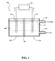
CO2をCOに電気化学的に還元するためのシステムが開示される。図1に示されるように、システム100は、アノードチャンバ102とカソードチャンバ104とを有する電解セルを含む。少なくとも2つのチャンバを有する任意の構成が用いられ得るが、図1の例は、アノードチャンバ102とカソードチャンバ104とがセパレータ106によって分離されるのを示す。使用の際には、そのようなセパレータ106は、気体を透過しない膜、すべての液体および気体の交換を防ぐバリア、またはアノードチャンバ102とカソードチャンバ104との間の気体交換を防ぐのに有効な任意の他のバリアであり得る。
A system for electrochemical reduction of CO 2 to CO is disclosed. As shown in FIG. 1,
アノードチャンバ102は、さらに、アノードチャンバ102に含まれるアノード液108と、アノード液108と接触するアノード110とを含む。カソードチャンバ104は、さらに、カソードチャンバ104に含まれるカソード液112と、カソード液112と接触するカソード114とを含む。
The
アノード液108とカソード液112とは、同じ組成であり得るが、必ずしもそうである必要はない。ある実現例では、カソード液112は水系の塩溶液であり、一部の実現例では、アノード液108およびカソード液112の両方が水系の塩溶液である。
The
アノード液108および/またはカソード液112における使用に対して好適な塩の非限定的な例は、炭酸塩もしくは重炭酸塩、硝酸塩、亜硝酸塩、硫酸塩、亜硫酸塩、リン酸塩もしくは任意の他の好適な塩のアルカリ金属またはアルカリ土類金属塩を含み得る。
Non-limiting examples of salts suitable for use in the
カソード114は陽極酸化処理された銀を含み、アノード110は、電気化学的酸化を支援するようアノード液108と電気化学的に互換性のある任意の材料からなり得る。
Cathode 114 includes anodized silver and
システム100は、加えて、電源116を含み、それは、カソード114とアノード110との間に電位を与えるよう構成される。電源116は、1つ以上の外部導電体を介するアノード110およびカソード114への電気的取付けのために構成され得、二酸化炭素の一酸化炭素への電気化学的還元を引起すのに十分なようにカソード114において電位を与えることができるべきである。
The
ある実現例においては、システム100は、さらに、気体入力部材118を含むことになり、それは、気体がカソード液112に接触してその中に溶解するように、カソードチャンバ104に気体を導入するための手段を含む。気体入力部材118は、気体または気体流をカソードチャンバ104に向けるための導管、開口部、または任意の他の手段を含み得る。ある実現例では、システム100は、選択肢的に、気体出力部材120を含み得、それは、生成物ガスがカソードチャンバ104を出るための手段を含む。
In certain implementations, the
システム100は、可能性として、以下の反応Iに従ってカソードの半反応に対応し得る:
CO2+4e−+4H+→CO+2H2O ...I
システム100は、可能性として、以下の反応IIに従って匹敵するカソードの半反応に対応し得る:
2H++2e−+→H2 ...II
反応Iをカソード114において生じさせるために、電源116は、少なくとも−0.7Vの電位(対Ag/AgCl)を与えるよう動作可能であり得る。ある例では、電源116は、カソード114において、−0.7Vより大きさが大きい負の電位(対Ag/AgCl)を与えることが好ましくてもよい。ある実現例では、電源116は、カソード114において、少なくとも−1.0Vの大きさを有する負の電位(対Ag/AgCl)を与え得る。ある実現例では、電源116は、カソード114において、−0.7〜−1.5Vの範囲内の負の電位(対Ag/AgCl)を与え得る。
The
CO 2 + 4e − + 4H + → CO + 2H 2 O. . . I
2H + + 2e − + → H 2 . . . II
In order to generate reaction I at the
さらに開示されるのは、二酸化炭素の電気化学的還元のための方法である。図2に示されるように、方法200は、電解セルを提供するステップ202を含む。電解セルは、上に記載されるとおりであり、アノード液108およびアノード110を伴うアノードチャンバ102と;カソード液112および陽極酸化処理された銀を含むカソード114を伴うカソードチャンバ104とを有する。方法200は、二酸化炭素をカソードチャンバ104に供給する別のステップ204を含み得る。この供給ステップは、たとえば、二酸化炭素を含むかまたは二酸化炭素が富化された気体流を気体入力部材118を介してカソードチャンバ104内に流入させることによって行なわれ得る。方法200は、加えて、カソードとアノードとの間に電位を与えるステップを含む。電位を与えるステップは、電位発生電源116をアノード110およびカソード114の各々に電気的に接触させることによって達成され得る。
Further disclosed is a method for electrochemical reduction of carbon dioxide. As shown in FIG. 2,
二酸化炭素の電気化学的還元のための方法200は、一般的には、アノードチャンバ102;アノード液108;アノード110;カソードチャンバ104;カソード液112;陽極酸化処理された銀を含むカソード114;および電源116の詳細な局面を含む電気化学セルの局面によって特徴付けられる。方法200において提供される電気化学セルは、さらに、システム100および図1を参照して上記されるように、選択肢的なセパレータ106、選択肢的な気体入力部材118、および選択肢的な気体出力部材120をさらに含み得る。
The
システム100および方法200の両方に関連して、カソード114は、あるプロセスによって準備されることができ、そのプロセスは、前駆体アノードを陽極酸化処理電解質と接触させて配置すること、および正の電位を前駆体アノードに与えることとを含む。前駆体アノードは元素として存在する銀を含有することになる。与えられる正の電位は基準電極に対してであり、陽極酸化電解質は銀の陽極酸化に対して好適な任意の電解質であり得る。好適な陽極酸化電解質の非限定的な例は、炭酸塩もしくは重炭酸塩、硝酸塩、亜硝酸塩、硫酸塩、亜硫酸塩、リン酸塩もしくは任意の他の好適な電解質の、アルカリ金属またはアルカリ土類金属塩の水溶液を含み得る。
In connection with both the
一部の実現例では、陽極酸化電位は指定された時間期間の間与えられ得、正の電位の大きさとその指定された期間との積は少なくとも3.75ボルト・分(V・分)である。一部の実現例では、正の電位の大きさと指定された期間との積は少なくとも11.25V・分である。一部の実現例では、正の電位の大きさと指定された期間との積は34.25V・分未満である。 In some implementations, the anodization potential can be applied for a specified time period, and the product of the positive potential magnitude and the specified period is at least 3.75 volts · min (V · min). is there. In some implementations, the product of the positive potential magnitude and the specified period is at least 11.25 V · min. In some implementations, the product of the positive potential magnitude and the specified period is less than 34.25 V · min.
ここで図3〜図7を参照して、二酸化炭素を一酸化炭素に電気化学的に還元するための4つの装置が準備された。これら4つの装置のうちの3つは、各々、本開示の方法200によって準備され動作されるシステム100の例である。これら3つの例示的な装置は、各々、白金の対向電極に対向して0.1MのNaNO3においてAg/AgClに対して0.75Vで5分、15分、または30分間陽極酸化処理されたカソード114を用いる。第4の装置は陽極酸化処理されない銀カソード(または0分間陽極酸化処理されたカソードとして記載される)を用い、したがって、開示されるシステム100または方法200の例ではないが、比較例である。
Referring now to FIGS. 3-7, four devices for electrochemical reduction of carbon dioxide to carbon monoxide were prepared. Three of these four devices are each examples of a
図3に示されるように、4つの装置の周期的なボルタンモグラムは、陽極酸化処理されない銀カソードを用いる比較例に対して、方法200によって準備され動作されるシステム100の3つの例については、(一般的に電流密度応答と称される、)最大電流密度における増大、および電流密度が上昇する与えられる電位における減少を示す。図3のデータは、さらに、電流密度応答は、5分の陽極酸化期間から15分の陽極酸化期間に増大するが、次いで、30分の陽極酸化期間で減少することも示す。
As shown in FIG. 3, the periodic voltammograms of the four devices are shown for three examples of the
図4に示されるように、カソードで放出される一酸化炭素のモル量対カソードで放出される一酸化炭素および水素のモル量の和として定義される、一酸化炭素生成選択性は、同様のパターンを示す。カソード114の陽極酸化に関連付けられる増大された一酸化炭素選択性のこの効果は、特に、より低く与えられる電位(または過電位)において特に明らかであり、〜0.5Vの過電位で動作された際に、陽極酸化されていない(0分間陽極酸化された)カソードを有する比較例に対する約5%の一酸化炭素選択性に対して、15分間陽極酸化処理されたカソード114を有するシステム100については60%近くの一酸化炭素選択性がある。
As shown in FIG. 4, the carbon monoxide production selectivity, defined as the sum of the molar amount of carbon monoxide released at the cathode versus the molar amount of carbon monoxide and hydrogen released at the cathode, is similar to Indicates a pattern. This effect of increased carbon monoxide selectivity associated with anodization of the
同様の傾向が、図5の一酸化炭素生成についてのファラデー効率において示される。たとえば、15分間陽極酸化処理されたカソード114を有するシステム100はすべての過電位において〜75%のファラデー効率を有するが、陽極酸化処理されないカソードを有する比較例はすべての過電位において〜50%の一酸化炭素生成に対するファラデー効率を有する。
A similar trend is shown in Faraday efficiency for carbon monoxide production in FIG. For example, a
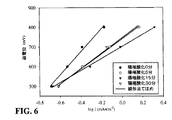
図6のタフェル図は同様に類似点がある応答を示す。タフェル傾斜は、0分〜5分〜15分の増大するカソード陽極酸化期間とともに減少する。しかしながら、30分間陽極酸化処理されたカソード114を有するシステム100のタフェル傾斜は減少を示し、それは、大部分、5分間陽極酸化処理されたカソード114を有するシステム100のそれと同一である。0分間、5分間、15分間および30分間陽極酸化処理されたカソードを有する装置に対するタフェル傾斜は、それぞれ、584mV/ディケード、381mV/ディケード、305mV/ディケードおよび390mV/ディケードである。
The Tafel diagram of FIG. 6 shows a response with similarities as well. The Tafel slope decreases with increasing cathode anodization period from 0 minutes to 5 minutes to 15 minutes. However, the Tafel slope of
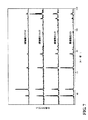
図7は、記載されるように0分間、5分間、15分間、および30分間の陽極酸化を受けたカソードの表面に関するx線回折(XRD)データを示す。これら4つのXRDデータの組は、すべて、約38°、43°、63°、78°、115°および118°に中心を有するピークを有するが、それらのピークの相対的な強度は、変動する陽極酸化期間とともに変化し、表面の銀の微結晶配向における変化を、銀の陽極酸化および陽極酸化期間の関数として示唆する。特に、約118°に中心を有するピークの強度は図3〜図6を参照して上で論じた傾向と同様であり、強度は、0〜15分間については増大するカソード陽極酸化期間とともに増大し、次いで、15分から30分のカソード陽極酸化期間からは減少する。 FIG. 7 shows x-ray diffraction (XRD) data for the surface of the cathode that was subjected to 0 min, 5 min, 15 min, and 30 min anodization as described. These four XRD data sets all have peaks centered at about 38 °, 43 °, 63 °, 78 °, 115 °, and 118 °, but the relative intensities of those peaks vary. It varies with the anodization period and suggests changes in the surface silver microcrystal orientation as a function of silver anodization and anodization period. In particular, the intensity of the peak centered at about 118 ° is similar to the trend discussed above with reference to FIGS. 3-6, with the intensity increasing with increasing cathode anodization period for 0-15 minutes. Then, it decreases from the cathode anodization period of 15 to 30 minutes.
この結果に基づいて、およびどのような特定の理論に拘束されることも意図せずに、銀カソード陽極酸化に関連付けられる、電流密度、一酸化炭素生成選択性、および一酸化炭素生成ファラデー効率における改善が、少なくとも一部、陽極酸化の結果の銀微結晶配向における変化に起因すると考えられる。特に、最大のCO2還元効率および選択性は、約43°に中心を有するXRDピークの強度に対する約118°に中心を有するXRDピークの強度の比の最大化に関連付けられることが注記され得る。ある例では、この比は少なくとも1:1であり得る。ある例では、この比は少なくとも2:1であり得る。「強度」という語、および「XRDピークの強度」という表現は、ここで用いられるとおりでは、当該ピーク下の領域を指し、最大ピーク高さを指すのではないことを理解されたい。 Based on this result, and without intending to be bound by any particular theory, in current density, carbon monoxide production selectivity, and carbon monoxide production faradaic efficiency associated with silver cathode anodization It is believed that the improvement is due, at least in part, to changes in silver crystallite orientation as a result of anodic oxidation. In particular, it can be noted that maximum CO 2 reduction efficiency and selectivity is associated with maximizing the ratio of the intensity of the XRD peak centered at about 118 ° to the intensity of the XRD peak centered at about 43 °. In certain instances, this ratio can be at least 1: 1. In certain instances, this ratio can be at least 2: 1. It is to be understood that the term “intensity” and the expression “XRD peak intensity” as used herein refers to the area under the peak and not the maximum peak height.
本開示のさまざまな局面を、さらに、以下の実施例に関して説明する。これらの実施例は、本開示の具体的な実施の形態を説明するよう与えられ、本開示の範囲を任意の特定の局面において、またはそれに対して限定するとして解釈されるべきではないことが理解される。 Various aspects of the disclosure are further described with reference to the following examples. These examples are provided to illustrate specific embodiments of the present disclosure, and it should be understood that the scope of the present disclosure should not be construed as limiting in or on any particular aspect. Is done.
実施例1.陽極酸化処理された銀カソードの調整
陽極酸化処理を、0.1MのNaNO3において、白金を対向電極として、およびAg/AgClを基準電極として行なった。0.75Vの電位(対Ag/AgCl)を、3つの別々の銀プレート電極に、それぞれ、5分間、15分間、または30分間与えた。
Example 1. Preparation of anodized silver cathode Anodization was performed in 0.1 M NaNO 3 with platinum as the counter electrode and Ag / AgCl as the reference electrode. A potential of 0.75 V (vs. Ag / AgCl) was applied to three separate silver plate electrodes for 5 minutes, 15 minutes, or 30 minutes, respectively.
実施例2.CO2の電気化学的還元のためのシステムの調整および動作
4つの2チャンバ電解セルが調整された。各々はKHCO3(0.1M、水系)電解質を含有するカソードチャンバおよびアノードチャンバを有し、各々のアノードチャンバは白金電極を含んだ。これら電気化学的還元システムのうちの3つは実施例1の陽極酸化された銀電極をカソードとして利用し、第4の電気化学的還元システムは、陽極酸化されていない銀プレート電極をカソードとして用いて、比較例とした。
Example 2 System adjustment and operation for electrochemical reduction of CO 2 Four two-chamber electrolysis cells were adjusted. Each had a cathode chamber and an anode chamber containing KHCO 3 (0.1M, aqueous) electrolyte, each anode chamber containing a platinum electrode. Three of these electrochemical reduction systems use the anodized silver electrode of Example 1 as the cathode, and the fourth electrochemical reduction system uses a non-anodized silver plate electrode as the cathode. Thus, a comparative example was obtained.
電解は、Ag/AgClを基準電極として行なった。KHCO3(0.1M、水系)は支持電解質として用いられた。CO2が少なくとも15分間電解質を通してパージされた後、各電解実験が開始された。各電解実験は、生じた全電荷の2クーロンの移動の後終了された。気相生成物を、ガスクロマトグラフィ(GC)を用いて解析した。 The electrolysis was performed using Ag / AgCl as a reference electrode. KHCO 3 (0.1M, aqueous) was used as the supporting electrolyte. Each electrolysis experiment was started after the CO 2 was purged through the electrolyte for at least 15 minutes. Each electrolysis experiment was terminated after a 2 coulomb transfer of the total charge generated. The gas phase product was analyzed using gas chromatography (GC).
前述の記載は現時点において最も実用的な実施の形態であると考えられるものに関する。しかしながら、この開示はこれらの実施の形態に限定されるものではなく、逆に、特許請求の範囲の精神および範囲内に含まれるさまざまな修正物および均等な構成を包含するよう意図されるものであり、その範囲は、法律の下許されるすべてのそのような修正物および均等な構造を包含するよう最も広い解釈に従うことになることが理解される。 The foregoing description relates to what is considered to be the most practical embodiment at the present time. However, this disclosure is not limited to these embodiments, and conversely, is intended to encompass various modifications and equivalent arrangements that fall within the spirit and scope of the appended claims. It is understood that the scope will be subject to the broadest interpretation to encompass all such modifications and equivalent structures permitted under the law.
100 システム、102 アノードチャンバ、104 カソードチャンバ、108 アノード液、110 アノード、112 カソード液、114 カソード。 100 system, 102 anode chamber, 104 cathode chamber, 108 anolyte, 110 anode, 112 catholyte, 114 cathode.
Claims (8)
銀元素を含有する前駆体電極を一定電位で陽極酸化処理して陽極酸化処理銀成分を得る陽極酸化ステップと、
電気化学セルを与えるステップを含み、前記電気化学セルは、
カソードチャンバを有し、前記カソードチャンバは、
カソード液と、
前記カソード液と接触するカソードとを含み、前記カソードは前記陽極酸化処理銀成分を含有し、
前記カソードの表面は約118°に中心を有するピークおよび約43°に中心を有するピークを有するX線回折パターンによって特徴付けられ、約43°に中心を有する前記ピークの強度に対する約118°に中心を有する前記ピークの強度の比率は、少なくとも1:1であり、
前記電気化学セルはさらに、
アノードチャンバを有し、前記アノードチャンバは、
アノード液と、
前記アノード液と接触するアノードとを含み、前記方法はさらに、
前記カソードチャンバに二酸化炭素を供給するステップと、
前記アノードと前記カソードとの間に電位を与えるステップとを含み、前記電位は前記カソードチャンバに存在する二酸化炭素を電気化学的に還元するのに十分である、二酸化炭素の電気化学的還元のための方法。 A method for the electrochemical reduction of carbon dioxide, comprising:
Anodizing step of obtaining an anodized silver component by anodizing a precursor electrode containing silver element at a constant potential;
Providing an electrochemical cell, the electrochemical cell comprising:
A cathode chamber, the cathode chamber comprising:
Catholyte,
A cathode in contact with the catholyte, the cathode containing the anodized silver component;
The cathode surface is characterized by an X-ray diffraction pattern having a peak centered at about 118 ° and a peak centered at about 43 °, centered at about 118 ° relative to the intensity of the peak centered at about 43 °. The ratio of the intensity of the peaks having at least 1: 1;
The electrochemical cell further comprises:
An anode chamber, the anode chamber comprising:
An anolyte,
An anode in contact with the anolyte, and the method further comprises:
Supplying carbon dioxide to the cathode chamber;
Applying a potential between the anode and the cathode, wherein the potential is sufficient to electrochemically reduce carbon dioxide present in the cathode chamber, for electrochemical reduction of carbon dioxide. the method of.
銀元素を含有する前駆体電極を一定電位で陽極酸化処理して陽極酸化処理銀成分を得る陽極酸化ステップと、
カソードチャンバを用意するステップと、
前記カソードチャンバとイオン接触するようにアノードチャンバを配置するステップと、を含み、
前記カソードチャンバは、カソード液と、前記カソード液と接触するカソードとを含み、前記カソードは前記陽極酸化処理銀成分を含有し、
前記カソードの表面は約118°に中心を有するピークおよび約43°に中心を有するピークを有するX線回折パターンによって特徴付けられ、約43°に中心を有する前記ピークの強度に対する約118°に中心を有する前記ピークの強度の比率は、少なくとも1:1であり、
前記アノードチャンバは、アノード液と、前記アノード液と接触するアノードとを含む、製造方法。 A method for producing an electrochemical cell for electrochemical reduction of carbon dioxide, comprising:
Anodizing step of obtaining an anodized silver component by anodizing a precursor electrode containing silver element at a constant potential;
Providing a cathode chamber;
Placing an anode chamber in ionic contact with the cathode chamber;
The cathode chamber includes a catholyte and a cathode in contact with the catholyte, the cathode containing the anodized silver component;
The cathode surface is characterized by an X-ray diffraction pattern having a peak centered at about 118 ° and a peak centered at about 43 °, centered at about 118 ° relative to the intensity of the peak centered at about 43 °. The ratio of the intensity of the peaks having at least 1: 1;
The anode chamber includes an anolyte and an anode in contact with the anolyte.
Applications Claiming Priority (2)
| Application Number | Priority Date | Filing Date | Title |
|---|---|---|---|
| US14/523,070 | 2014-10-24 | ||
| US14/523,070 US9435042B2 (en) | 2014-10-24 | 2014-10-24 | System and method for selective electrochemical reduction of carbon dioxide employing an anodized silver electrode |
Publications (3)
| Publication Number | Publication Date |
|---|---|
| JP2016084535A JP2016084535A (en) | 2016-05-19 |
| JP2016084535A5 JP2016084535A5 (en) | 2017-04-20 |
| JP6200475B2 true JP6200475B2 (en) | 2017-09-20 |
Family
ID=55791525
Family Applications (1)
| Application Number | Title | Priority Date | Filing Date |
|---|---|---|---|
| JP2015208816A Active JP6200475B2 (en) | 2014-10-24 | 2015-10-23 | System and method for electrochemical reduction of carbon dioxide |
Country Status (2)
| Country | Link |
|---|---|
| US (1) | US9435042B2 (en) |
| JP (1) | JP6200475B2 (en) |
Families Citing this family (2)
| Publication number | Priority date | Publication date | Assignee | Title |
|---|---|---|---|---|
| JP6779849B2 (en) * | 2017-09-19 | 2020-11-04 | 株式会社東芝 | Carbon dioxide reduction catalyst and its production method, reduction electrode, and reduction reactor |
| KR102553922B1 (en) * | 2021-03-19 | 2023-07-10 | 울산과학기술원 | Secondary battery using carbon dioxide and complex electric power generation system having the same |
Family Cites Families (7)
| Publication number | Priority date | Publication date | Assignee | Title |
|---|---|---|---|---|
| US2315518A (en) * | 1939-10-03 | 1943-04-06 | Marion H Gwynn | Method of activating catalytic surfaces |
| US4461677A (en) * | 1983-07-05 | 1984-07-24 | The United States Of America As Represented By The Secretary Of The Navy | Process for charging silver electrodes to monoxide level |
| CN101235515B (en) | 2008-02-27 | 2010-06-23 | 浙江工业大学 | Method for preparing active silver electrode |
| US8592633B2 (en) | 2010-07-29 | 2013-11-26 | Liquid Light, Inc. | Reduction of carbon dioxide to carboxylic acids, glycols, and carboxylates |
| WO2013016447A2 (en) * | 2011-07-26 | 2013-01-31 | The Board Of Trustees Of The Leland Stanford Junior University | Catalysts for low temperature electrolytic co2 reduction |
| US9175407B2 (en) * | 2012-07-26 | 2015-11-03 | Liquid Light, Inc. | Integrated process for producing carboxylic acids from carbon dioxide |
| ES2670972T3 (en) | 2012-08-23 | 2018-06-04 | Trustees Of Princeton University | Reduction of carbon dioxide in products with an indium oxide electrode |
-
2014
- 2014-10-24 US US14/523,070 patent/US9435042B2/en active Active
-
2015
- 2015-10-23 JP JP2015208816A patent/JP6200475B2/en active Active
Also Published As
| Publication number | Publication date |
|---|---|
| US20160115605A1 (en) | 2016-04-28 |
| JP2016084535A (en) | 2016-05-19 |
| US9435042B2 (en) | 2016-09-06 |
Similar Documents
| Publication | Publication Date | Title |
|---|---|---|
| US9062382B2 (en) | Electrolytic cells and methods for the production of ammonia and hydrogen | |
| JP2525553B2 (en) | Electrodialysis tank and electrodialysis method | |
| CN101634035B (en) | Electrochemical method and electrochemical device for synergistically generating ozone and hydrogen peroxide in neutral medium | |
| JP5604204B2 (en) | Ammonia synthesis method | |
| KR101793711B1 (en) | Device and Method for preparing carbonate and/or formate from carbon dioxide | |
| AU2010201005A1 (en) | Low-voltage alkaline production using hydrogen and electrocatlytic electrodes | |
| CN110268099B (en) | Pulsed electrolysis with reference to open circuit potential | |
| Jianping et al. | Preparation of a silver electrode with a three-dimensional surface and its performance in the electrochemical reduction of carbon dioxide | |
| KR20150101776A (en) | Method for improving activity of oxygen evolution reaction and Ni catalysts used therein | |
| CN109852992A (en) | Water nano-chip arrays electrode and its preparation method and application is decomposed in a kind of efficient electro-catalysis entirely | |
| Zhang et al. | Electrochemical reduction of carbon dioxide to formate with a Sn cathode and an Ir x Sn y Ru z O 2/Ti anode | |
| JP6931769B2 (en) | Electrolyzers and methods that electrochemically reduce carbon dioxide to produce ethylene | |
| JP6200475B2 (en) | System and method for electrochemical reduction of carbon dioxide | |
| JP6221067B2 (en) | Formic acid production apparatus and method | |
| JP2015004112A (en) | Electrolytic synthesis device | |
| JP2008274391A (en) | Hydrogen generating apparatus and fuel cell system using the same | |
| Modisha et al. | Electrocatalytic process for ammonia electrolysis: a remediation technique with hydrogen co-generation | |
| KR20170106608A (en) | The catalyst for reducing carbon dioxide and oxydizing formic acid and preparation therof | |
| JPH04314881A (en) | Electrolytic device | |
| JP2005293901A (en) | Fuel cell system and driving method thereof | |
| JP2008138282A (en) | Anode for alkaline electrolysis | |
| EP3781726B1 (en) | Photovoltaic-electrochemical (pv-ec) system | |
| KR20220068566A (en) | Hydrogen generation apparatus using aqueous ammonia | |
| KR20190107876A (en) | Reduction system of carbon dioxide and method of reducing carbon dioxide using the same | |
| CN110678580B (en) | Hydrogen generator and hydrogen generating method |
Legal Events
| Date | Code | Title | Description |
|---|---|---|---|
| A521 | Request for written amendment filed |
Free format text: JAPANESE INTERMEDIATE CODE: A523 Effective date: 20170314 |
|
| A621 | Written request for application examination |
Free format text: JAPANESE INTERMEDIATE CODE: A621 Effective date: 20170314 |
|
| A871 | Explanation of circumstances concerning accelerated examination |
Free format text: JAPANESE INTERMEDIATE CODE: A871 Effective date: 20170314 |
|
| A975 | Report on accelerated examination |
Free format text: JAPANESE INTERMEDIATE CODE: A971005 Effective date: 20170404 |
|
| A131 | Notification of reasons for refusal |
Free format text: JAPANESE INTERMEDIATE CODE: A131 Effective date: 20170418 |
|
| A521 | Request for written amendment filed |
Free format text: JAPANESE INTERMEDIATE CODE: A523 Effective date: 20170714 |
|
| TRDD | Decision of grant or rejection written | ||
| A01 | Written decision to grant a patent or to grant a registration (utility model) |
Free format text: JAPANESE INTERMEDIATE CODE: A01 Effective date: 20170801 |
|
| A61 | First payment of annual fees (during grant procedure) |
Free format text: JAPANESE INTERMEDIATE CODE: A61 Effective date: 20170825 |
|
| R150 | Certificate of patent or registration of utility model |
Ref document number: 6200475 Country of ref document: JP Free format text: JAPANESE INTERMEDIATE CODE: R150 |
|
| S111 | Request for change of ownership or part of ownership |
Free format text: JAPANESE INTERMEDIATE CODE: R313113 |
|
| R350 | Written notification of registration of transfer |
Free format text: JAPANESE INTERMEDIATE CODE: R350 |