JP2005293901A - Fuel cell system and driving method thereof - Google Patents
Fuel cell system and driving method thereof Download PDFInfo
- Publication number
- JP2005293901A JP2005293901A JP2004103939A JP2004103939A JP2005293901A JP 2005293901 A JP2005293901 A JP 2005293901A JP 2004103939 A JP2004103939 A JP 2004103939A JP 2004103939 A JP2004103939 A JP 2004103939A JP 2005293901 A JP2005293901 A JP 2005293901A
- Authority
- JP
- Japan
- Prior art keywords
- electrode
- fuel cell
- fuel
- cell system
- potential
- Prior art date
- Legal status (The legal status is an assumption and is not a legal conclusion. Google has not performed a legal analysis and makes no representation as to the accuracy of the status listed.)
- Pending
Links
Images

Classifications
-
- Y—GENERAL TAGGING OF NEW TECHNOLOGICAL DEVELOPMENTS; GENERAL TAGGING OF CROSS-SECTIONAL TECHNOLOGIES SPANNING OVER SEVERAL SECTIONS OF THE IPC; TECHNICAL SUBJECTS COVERED BY FORMER USPC CROSS-REFERENCE ART COLLECTIONS [XRACs] AND DIGESTS
- Y02—TECHNOLOGIES OR APPLICATIONS FOR MITIGATION OR ADAPTATION AGAINST CLIMATE CHANGE
- Y02E—REDUCTION OF GREENHOUSE GAS [GHG] EMISSIONS, RELATED TO ENERGY GENERATION, TRANSMISSION OR DISTRIBUTION
- Y02E60/00—Enabling technologies; Technologies with a potential or indirect contribution to GHG emissions mitigation
- Y02E60/30—Hydrogen technology
- Y02E60/50—Fuel cells
Landscapes
- Fuel Cell (AREA)
- Inert Electrodes (AREA)
Abstract
【課題】 燃料電池システムにおいて、燃料極のCO被毒や酸化被膜の形成を防止することにより、燃料電池の出力を向上させる。
【解決手段】 燃料電池システム100は、燃料124が供給される燃料極102と、酸化剤が供給される酸化剤極108と、およびこれらに挟持された固体電解質膜114と、を備えた単位セル構造101と、燃料極102に配して設けられ、燃料124を収容する容器142と、容器142内に設けられた第三の電極140と、燃料極102と第三の電極140との間に電圧を印加する印加電圧制御部144と、を含む。
【選択図】 図1
PROBLEM TO BE SOLVED: To improve output of a fuel cell by preventing CO poisoning of a fuel electrode and formation of an oxide film in a fuel cell system.
SOLUTION: A fuel cell system 100 includes a unit cell including a fuel electrode 102 to which a fuel 124 is supplied, an oxidant electrode 108 to which an oxidant is supplied, and a solid electrolyte membrane 114 sandwiched therebetween. Between the structure 101, the fuel electrode 102, the container 142 that contains the fuel 124, the third electrode 140 provided in the container 142, and between the fuel electrode 102 and the third electrode 140 An applied voltage control unit 144 for applying a voltage.
[Selection] Figure 1
Description
本発明は、燃料電池システムおよびその駆動方法に関する。 The present invention relates to a fuel cell system and a driving method thereof.
燃料電池は、低公害でエネルギー効率に優れた発電システムとして、近年注目を集めている。燃料電池には、使用する燃料や電解質の種類、作動温度等によって種々のタイプのものが知られているが、特にメタノールを燃料とするダイレクトメタノール燃料電池(以下、DMFC)は、安全性、携帯性、長時間駆動性などの利点から、従来のリチウムイオン電池に代わる移動端末機器用の電源として、急速に開発が進められている。 In recent years, fuel cells have attracted attention as a power generation system with low pollution and excellent energy efficiency. Various types of fuel cells are known depending on the type of fuel and electrolyte used, the operating temperature, etc. Direct methanol fuel cells (hereinafter referred to as DMFC) using methanol as fuel are particularly safe and portable. As a power source for mobile terminal equipment that replaces the conventional lithium ion battery, it has been rapidly developed.
DMFCは、メタノールを燃料極に直接供給して発電させる固体高分子型燃料電池の一つであり、燃料極(アノード)での反応は、以下の式(1)のようになる。 DMFC is one of solid polymer fuel cells that generate electricity by directly supplying methanol to the fuel electrode, and the reaction at the fuel electrode (anode) is represented by the following formula (1).
CH3OH + H2O → 6H+ + 6e− + CO2 ・・・・(1) CH 3 OH + H 2 O → 6H + + 6e − + CO 2 ... (1)
また、酸化剤極(カソード)での反応は、以下の式(2)のようになる。 The reaction at the oxidant electrode (cathode) is represented by the following formula (2).
O2 + 4H+ + 4e− → 2H2O ・・・・・・・・・・・・(2) O 2 + 4H + + 4e − → 2H 2 O (2)
燃料極触媒上にメタノール燃料を供給すると、燃料が酸化される過程でプロトンと電子を生じる。プロトンは電解質膜を通じて、電子は外部負荷回路を通じて、それぞれ酸化剤極に移動する。一方、酸化剤極触媒上では、酸素の還元と共に(2)の反応が進行し、その結果、電池回路としての電気エネルギーが得られる。 When methanol fuel is supplied onto the fuel electrode catalyst, protons and electrons are generated in the process of oxidizing the fuel. Protons move through the electrolyte membrane and electrons move through the external load circuit to the oxidant electrode. On the other hand, on the oxidant electrode catalyst, the reaction (2) proceeds with the reduction of oxygen, and as a result, electric energy as a battery circuit is obtained.
DMFCの出力は、(1)の反応に強く依存することが知られており、反応の中間生成物である一酸化炭素(CO)が、燃料極触媒表面に強く吸着し、反応の進行を阻害する「CO被毒」と呼ばれる現象が知られている。これにより、燃料電池の出力が低下すると考えられている。 The output of DMFC is known to strongly depend on the reaction of (1), and carbon monoxide (CO), which is an intermediate product of the reaction, is strongly adsorbed on the anode catalyst surface and inhibits the progress of the reaction. A phenomenon called “CO poisoning” is known. This is thought to reduce the output of the fuel cell.
このような問題を解決するために、たとえば、特許文献1には、燃料極に正の電位を印加する手段を設けた燃料電池システムが開示されている。また、特許文献2には、アノード(燃料極)の電位を制御してCOを酸化することにより、アノードガス中のCOの濃度を低下させる技術が開示されている。また、特許文献3には、陽極(燃料極)に単数または繰り返しの正の電圧パルスを印加する技術が開示されている。
In order to solve such a problem, for example,
また、非特許文献1には、燃料電池の発電を続けると、燃料極触媒表面には酸化被膜(Pt−OまたはPt−OH)が形成し、触媒性能が失われるため、出力が著しく低下することが報告されている。
しかし、燃料極触媒として通常使用されるPt系材料は、長時間使用により金属成分が電解質膜中に溶解し、回路の短絡を引き起こすことが指摘されている。これは、燃料電池を高電位で作動させた場合に顕著な現象である。そのため、上記特許文献1〜3に記載されたように、燃料極に正の電荷を印加する方法では、高電位の状態が断続的に続くため、燃料極の酸化および溶解が促進され、燃料電池の寿命を著しく縮めてしまうおそれがある。
However, it has been pointed out that a Pt-based material usually used as a fuel electrode catalyst dissolves a metal component in an electrolyte membrane when used for a long time, causing a short circuit. This is a remarkable phenomenon when the fuel cell is operated at a high potential. Therefore, as described in
また、上記特許文献1〜3に記載されたように、燃料極に正の電荷を印加するだけでは、燃料極触媒表面に形成された酸化被膜を除去することはできない。
Further, as described in
本発明は、上記事情を踏まえてなされたものであり、本発明の目的は、燃料電池システムにおいて、燃料極のCO被毒や酸化被膜の形成を防止することにより、燃料電池の出力を向上させる技術を提供することにある。 The present invention has been made in view of the above circumstances, and an object of the present invention is to improve the output of the fuel cell by preventing CO poisoning of the fuel electrode and formation of an oxide film in the fuel cell system. To provide technology.
図11は、電極の触媒としてPtを用い、電極に印加する電位を変化させたときの触媒表面におけるメタノールの酸化反応を電気化学的に調べたサイクリックボルタモグラムを示す図である。図11において、矢印(1)で示した付近から高電位側で電流が増加しているのは、メタノールの酸化速度の増加を表す。0.6V付近(銀/塩化銀電極基準)においてメタノールの酸化反応はピークとなる。しかし、これより高電位側では、吸着OHの生成が優勢となり、Pt上に触媒不活性な酸化被膜が形成し、メタノールの酸化反応が抑制される。一方、1.5V付近(銀/塩化銀電極基準)から電位を低下させると、Pt上の酸化被膜は徐々に還元され、再び活性なPt表面が現れるようになる。さらに、矢印(3)付近まで電位を下げると、水の還元が始まり、水素が発生する。 FIG. 11 is a diagram showing a cyclic voltammogram obtained by electrochemically examining the oxidation reaction of methanol on the catalyst surface when Pt is used as the electrode catalyst and the potential applied to the electrode is changed. In FIG. 11, the increase in current on the high potential side from the vicinity indicated by the arrow (1) indicates an increase in the oxidation rate of methanol. The oxidation reaction of methanol reaches a peak at around 0.6 V (silver / silver chloride electrode standard). However, on the higher potential side, the generation of adsorbed OH becomes dominant, and a catalyst-inactive oxide film is formed on Pt, so that the oxidation reaction of methanol is suppressed. On the other hand, when the potential is lowered from around 1.5 V (silver / silver chloride electrode reference), the oxide film on Pt is gradually reduced, and the active Pt surface appears again. Further, when the potential is lowered to the vicinity of the arrow (3), the reduction of water starts and hydrogen is generated.
本発明者らは、図11に示したサイクリックボルタモグラムの結果に基づき、メタノールの酸化反応および触媒の表面状態が、電極に印加する電位に依存することから、電極の電位を制御することにより燃料の酸化反応を制御することが可能なことを見出し、本発明を想到するに至った。 Based on the results of the cyclic voltammogram shown in FIG. 11, the inventors of the present invention are that the oxidation reaction of methanol and the surface state of the catalyst depend on the potential applied to the electrode. The present inventors have found that it is possible to control the oxidation reaction of the present invention and arrived at the present invention.
本発明によれば、液体燃料が供給される第一の電極と、酸化剤が供給される第二の電極と、これらに挟持された電解質膜と、を備えた単位セルと、前記第一の電極に離隔して設けられた第三の電極と、第一の電極と第三の電極との間に電圧を印加する電圧印加手段と、を含むことを特徴とする燃料電池システムが提供される。 According to the present invention, a unit cell comprising a first electrode to which liquid fuel is supplied, a second electrode to which an oxidant is supplied, and an electrolyte membrane sandwiched therebetween, and the first cell There is provided a fuel cell system comprising: a third electrode spaced apart from the electrode; and voltage applying means for applying a voltage between the first electrode and the third electrode. .
ここで、第一の電極は燃料極、第二の電極は酸化剤極である。第三の電極は、単位セルの電池反応に寄与しない電極である。 Here, the first electrode is a fuel electrode, and the second electrode is an oxidant electrode. The third electrode is an electrode that does not contribute to the battery reaction of the unit cell.
第三の電極は、白金、金、銀、パラジウム、ルテニウム、イリジウム、ロジウム、レニウム、オスミウム、スズ、鉄、銅、ニッケル、コバルト、チタン、ジルコニウム、ステンレス、カーボンから選ばれる少なくとも1種あるいは2種以上の材料、あるいはこれらの合金または酸化物が表面に露出した構成とすることができる。第三の電極としては、これらの中でも、白金、金、銀等の比較的水素過電圧の低い材料を用いることができる。また、第一の電極、第二の電極、および第三の電極は、平板状、メッシュ状、穴があいた板状、スポンジ状、多孔質状等、電極の表面積が広くなるような構造とすることができる。 The third electrode is at least one or two selected from platinum, gold, silver, palladium, ruthenium, iridium, rhodium, rhenium, osmium, tin, iron, copper, nickel, cobalt, titanium, zirconium, stainless steel, and carbon. The above materials, or their alloys or oxides may be exposed on the surface. Among these, materials having a relatively low hydrogen overvoltage such as platinum, gold, and silver can be used as the third electrode. The first electrode, the second electrode, and the third electrode have a structure that increases the surface area of the electrode, such as a flat plate shape, a mesh shape, a plate shape with a hole, a sponge shape, and a porous shape. be able to.
また、第一の電極は、触媒を含むことができる。第一の電極の触媒としては、PtまたはPtとRuの合金を用いることができる。また、液体燃料としては、メタノール等のアルコールを含む水溶液を用いることができる。 The first electrode can include a catalyst. As the catalyst for the first electrode, Pt or an alloy of Pt and Ru can be used. As the liquid fuel, an aqueous solution containing alcohol such as methanol can be used.
本発明の燃料電池システムにおいて、第一の電極と第三の電極との間に電圧を印加することにより、第一の電極で生じるCO被毒や酸化被膜の形成を防止することができる。また、第一の電極の電位を変動させることにより、第一の電極の触媒表面を活性な状態に維持することができるため、燃料電池の出力を向上させることもできる。また、燃料電池システムに第三の電極を設け、この第三の電極と第一の電極との間に電圧を印加するため、少ない消費電力で効果的に第一の電極の電位を制御することができる。また、従来のように燃料極に直接電荷を印加するのではなく、第三の電極と燃料極間に電圧を印加するため、電圧印加による単位セルや電解質膜の損傷を防ぐことができる。 In the fuel cell system of the present invention, by applying a voltage between the first electrode and the third electrode, it is possible to prevent CO poisoning and oxide film formation that occur at the first electrode. Moreover, since the catalyst surface of the first electrode can be maintained in an active state by changing the potential of the first electrode, the output of the fuel cell can also be improved. In addition, since a third electrode is provided in the fuel cell system and a voltage is applied between the third electrode and the first electrode, the potential of the first electrode can be effectively controlled with low power consumption. Can do. Further, since the voltage is applied between the third electrode and the fuel electrode instead of directly applying the charge to the fuel electrode as in the prior art, damage to the unit cell and the electrolyte membrane due to the voltage application can be prevented.
本発明の燃料電池システムは、第一の電極に配して設けられ、液体燃料が満たされた燃料供給系をさらに含むことができ、第三の電極は、燃料供給系内に設けることができる。ここで、燃料供給系は、容器や液体燃料が通過する液体流路である。燃料供給系は、液体燃料で完全に満たされている必要はない。 The fuel cell system of the present invention may further include a fuel supply system provided on the first electrode and filled with liquid fuel, and the third electrode may be provided in the fuel supply system. . Here, the fuel supply system is a liquid flow path through which a container or liquid fuel passes. The fuel supply system need not be completely filled with liquid fuel.
本発明の燃料電池システムにおいて、電圧印加手段は、第一の電位と、第一の電位よりも低い第二の電位とを交互に印加することができる。 In the fuel cell system of the present invention, the voltage application means can alternately apply the first potential and the second potential lower than the first potential.
本発明において、このように、比較的高い第一の電極と第一の電極よりも低い第二の電極とを交互に印加することにより、第一の電極のCO被毒を防ぐとともに、酸化被膜を抑制することができる。 In the present invention, the first electrode and the second electrode lower than the first electrode are alternately applied in this way, thereby preventing CO poisoning of the first electrode and preventing the oxide film. Can be suppressed.
上述したように、液体燃料としてメタノールを用いた場合、燃料極においてメタノールが酸化され、これにより燃料電池の電気化学反応が生じる。メタノールの酸化は、以下のようにしておこる。まず、燃料極において、COがPt上に吸着する。この吸着CO(Pt−COads)は、水が分解して生じたOHラジカルがPt上に吸着した吸着OH(Pt−OHads)との反応により、CO2に酸化される。吸着OH(Pt−OHads)は、高電位側で生成しやすい。しかし、高電位側では、吸着OH(Pt−OHads)の生成とともにPt表面の酸化が進行し、触媒作用が低下するため、逆にメタノールの酸化反応が抑制される。 As described above, when methanol is used as the liquid fuel, methanol is oxidized at the fuel electrode, thereby causing an electrochemical reaction of the fuel cell. Methanol is oxidized as follows. First, CO adsorbs on Pt at the fuel electrode. The adsorbed CO (Pt—CO ads ) is oxidized to CO 2 by a reaction with adsorbed OH (Pt—OH ads ) in which OH radicals generated by the decomposition of water are adsorbed on Pt. Adsorbed OH (Pt—OH ads ) is likely to be generated on the high potential side. However, on the high potential side, the oxidation of the Pt surface proceeds with the generation of adsorbed OH (Pt—OH ads ), and the catalytic action decreases, so the methanol oxidation reaction is conversely suppressed.
本発明の燃料電池システムにおいて、第一の電位は、第一の電極周囲の液体燃料中でOHラジカルが生じる電位とすることができる。このような第一の電位を印加することにより、第一の電極で生じたCO被毒を抑制することができる。また、このような第一の電位を印加することにより、液体燃料の酸化を促進することもでき、これによっても燃料電池システムの出力が増加する。第一の電位は、たとえば0.3V(銀/塩化銀電極基準)以上とすることができる。 In the fuel cell system of the present invention, the first potential can be a potential at which OH radicals are generated in the liquid fuel around the first electrode. By applying such a first potential, CO poisoning generated in the first electrode can be suppressed. In addition, by applying such a first potential, it is possible to promote the oxidation of the liquid fuel, which also increases the output of the fuel cell system. The first potential can be, for example, 0.3 V (silver / silver chloride electrode reference) or more.
本発明の燃料電池システムにおいて、第二の電位は、第一の電極周囲の液体燃料中でHラジカルが生じる電位とすることができる。このような第二の電位を印加することにより、第一の電極に生じた酸化被膜を還元して活性な触媒表面を得ることができる。なお、液体燃料としてメタノールを用いた場合、メタノールの酸化反応は不可逆的であるため、第一の電位よりも低い第二の電位を印加しても、酸化生成物から再びメタノールが生成する逆反応が起こることもない。第二の電位は、たとえば0.6V(銀/塩化銀電極基準)以下とすることができる。 In the fuel cell system of the present invention, the second potential can be a potential at which H radicals are generated in the liquid fuel around the first electrode. By applying such a second potential, the oxide film formed on the first electrode can be reduced to obtain an active catalyst surface. When methanol is used as the liquid fuel, the oxidation reaction of methanol is irreversible, so even if a second potential lower than the first potential is applied, the reverse reaction in which methanol is generated again from the oxidized product. Will never happen. The second potential can be, for example, 0.6 V (silver / silver chloride electrode reference) or less.
本発明の燃料電池システムにおいて、電圧印加手段は、第一の電位および第二の電位をそれぞれピークとする交流電圧を印加することができる。 In the fuel cell system of the present invention, the voltage application means can apply an alternating voltage having peaks at the first potential and the second potential.
ここで、交流とは、時間と共に電圧(または電流値)と電流の向きの少なくともいずれかが変化する状態を指す。このように、第一の電極および第二の電極に交流電圧を印加することにより、第一の電極および第一の電極の触媒の電位が周期的に変化する。このように、第一の電極の触媒の電位が第一の電位と第二の電位の間の一定電位内で上昇と下降を繰り返すことにより、触媒表面に形成されたCOや酸化被膜が電気化学的に分解または脱離し、活性な触媒表面を得ることができる。 Here, alternating current refers to a state in which at least one of voltage (or current value) and current direction changes with time. Thus, by applying an alternating voltage to the first electrode and the second electrode, the potential of the catalyst of the first electrode and the first electrode changes periodically. As described above, when the potential of the catalyst of the first electrode repeatedly rises and falls within a constant potential between the first potential and the second potential, the CO and oxide film formed on the catalyst surface are electrochemically reacted. Can be decomposed or desorbed to obtain an active catalyst surface.
本発明の電圧印加手段は、電源とファンクションジェネレータとにより構成することができる。なお、ここで、交流とは、正弦波のほか、パルス、矩形波、三角波、台形波、階段波、または任意に作成した定常波とすることができる。 The voltage application means of the present invention can be constituted by a power supply and a function generator. Here, the AC can be a sine wave, a pulse, a rectangular wave, a triangular wave, a trapezoidal wave, a staircase wave, or an arbitrarily created standing wave.
本発明によれば、第一の電極の電位が、正方向および負方向に交互に変化するため、たとえ正方向の電位変動時に電極の酸化が生じた場合も、負方向の電位変動時に還元されるため、全体として電極の酸化が防止でき、上述した長時間駆動に伴う電極成分の溶解の問題を解消することもできる。 According to the present invention, since the potential of the first electrode changes alternately in the positive direction and the negative direction, even if the electrode is oxidized during the potential fluctuation in the positive direction, it is reduced during the potential fluctuation in the negative direction. Therefore, oxidation of the electrode as a whole can be prevented, and the above-described problem of dissolution of the electrode components accompanying long-time driving can also be solved.
本発明の燃料電池システムにおいて、第一の電位と第二の電位の電位差は、0.01V以上とすることができる。これにより、CO被毒の低減および酸化被膜の抑制を実効的に行うことができる。また、第一の電位と第二の電位の電位差は、2V以下とすることができる。これにより電解質膜や燃料電池回路へダメージを与えることなく、燃料電池の出力を向上することができる。 In the fuel cell system of the present invention, the potential difference between the first potential and the second potential can be 0.01 V or more. Thereby, reduction of CO poisoning and suppression of an oxide film can be performed effectively. Further, the potential difference between the first potential and the second potential can be 2 V or less. Thereby, the output of the fuel cell can be improved without damaging the electrolyte membrane and the fuel cell circuit.
本発明の燃料電池システムにおいて、電圧印加手段は、第一の電位と第二の電位とを、下記の一般式で表される間隔Δtで印加することができる。
0.005≦|ΔV|/Δt≦50
(ここで、ΔVは第一の電位と第二の電位との差を示す。)
In the fuel cell system of the present invention, the voltage application means can apply the first potential and the second potential at an interval Δt represented by the following general formula.
0.005 ≦ | ΔV | / Δt ≦ 50
(Here, ΔV represents the difference between the first potential and the second potential.)
時間の間隔Δtをこのような範囲とすることにより、OHラジカルの発生やPt−OHの還元を効率よく行うことができる。 By setting the time interval Δt in such a range, generation of OH radicals and reduction of Pt—OH can be performed efficiently.
本発明の燃料電池システムにおいて、第三の電極は、第一の電極に対向して設けることができる。 In the fuel cell system of the present invention, the third electrode can be provided to face the first electrode.
このように、第一の電極に対向して設けられた第三の電極と第一の電極との間に電圧を印加することにより、電圧の印加よる消費電力を少なくすることができ、投入エネルギーを低く抑えることができる。また、燃料電池の電気化学反応に寄与する電極とは異なる第三の電極と第一の電極との間に電圧を印加するので、単位セルや電解質膜に対しても、過剰な電気負荷を与えることがなく、燃料電池システムの損傷を防止することができる。 Thus, by applying a voltage between the third electrode and the first electrode provided opposite to the first electrode, the power consumption due to the application of the voltage can be reduced, and the input energy Can be kept low. In addition, since a voltage is applied between the third electrode different from the electrode that contributes to the electrochemical reaction of the fuel cell and the first electrode, an excessive electric load is also applied to the unit cell and the electrolyte membrane. In this way, damage to the fuel cell system can be prevented.
本発明の燃料電池システムにおいて、第三の電極は、第一の電極に略平行に設けることができ、第一の電極と第三の電極との電極間距離は、100mm以下とすることができる。電極間距離をこのようにすることにより、電極間に生じる電界を強めることができ、より顕著な効果を得ることができる。第一の電極と第三の電極との電極間距離は、より好ましくは50mm以下とすることができる。 In the fuel cell system of the present invention, the third electrode can be provided substantially parallel to the first electrode, and the distance between the first electrode and the third electrode can be 100 mm or less. . By setting the distance between the electrodes in this way, the electric field generated between the electrodes can be strengthened, and a more remarkable effect can be obtained. More preferably, the interelectrode distance between the first electrode and the third electrode can be 50 mm or less.
また、第一の電極と第三の電極との電極間距離の下限はとくに限定されないが、たとえば50μm以上、より好ましくは100μm以上とすることができる。これにより、特殊な設計技術を必要とすることなく、既存の絶縁体等のスぺーサー等を利用して電極間距離を制御できるため、セルの設計面において大きな利点が得られる。また、電極間距離をこの程度とすることにより、実用の際に外部からの衝撃や圧力によっても、電極同士が接触することなく、交流回路の短絡を防ぐことができる。 Further, the lower limit of the interelectrode distance between the first electrode and the third electrode is not particularly limited, but may be, for example, 50 μm or more, more preferably 100 μm or more. Thus, since the distance between the electrodes can be controlled using a spacer such as an existing insulator without requiring a special design technique, a great advantage can be obtained in terms of cell design. Further, by setting the distance between the electrodes to this level, it is possible to prevent a short circuit of the AC circuit without contacting the electrodes due to an impact or pressure from the outside during practical use.
本発明の燃料電池システムにおいて、第一の電極と第三の電極との間には、電気伝導性領域を設けることができる。 In the fuel cell system of the present invention, an electrically conductive region can be provided between the first electrode and the third electrode.
電気伝導性領域は、たとえば液体燃料中に電解質を添加することにより実現することができる。また、第一の電極と第三の電極との間に電解質膜等のシートを狭持させることにより、電極間に電気伝導性領域を設けることもできる。 The electrically conductive region can be realized, for example, by adding an electrolyte to the liquid fuel. In addition, an electrically conductive region can be provided between the electrodes by sandwiching a sheet such as an electrolyte membrane between the first electrode and the third electrode.
本発明の燃料電池システムは、平面状に配置された複数の単位セルを含むことができる。ここで、第三の電極は、複数の単位セルに共有で設けられることができる。また、本発明の燃料電池システムは、複数の第三の電極を含み、複数の単位セルの複数の第一の電極それぞれに第三の電極が設けられてもよい。 The fuel cell system of the present invention can include a plurality of unit cells arranged in a plane. Here, the third electrode can be shared by a plurality of unit cells. The fuel cell system of the present invention may include a plurality of third electrodes, and a third electrode may be provided on each of the plurality of first electrodes of the plurality of unit cells.
本発明の燃料電池システムは、平面状に配置された複数の単位セルを含むことができ、第三の電極は、少なくとも2以上の単位セルの第一の電極に共有で設けられてよい。第三の電極を複数の単位セルに共有で設ける場合、第三の電極は、複数の第一の電極に対向して設けられたときに、これらの複数の第一の電極を覆う大きさに形成される。 The fuel cell system of the present invention may include a plurality of unit cells arranged in a plane, and the third electrode may be provided in common with the first electrodes of at least two or more unit cells. When the third electrode is provided in common to the plurality of unit cells, the third electrode is sized to cover the plurality of first electrodes when provided opposite to the plurality of first electrodes. It is formed.
これにより、複数の単位セルが含まれる燃料電池システムにおいても、簡易な構成でCO被毒の防止および酸化被膜の抑制を行うことができる。 As a result, even in a fuel cell system including a plurality of unit cells, it is possible to prevent CO poisoning and suppress an oxide film with a simple configuration.
本発明によれば、液体燃料が供給される第一の電極と、酸化剤が供給される第二の電極と、これらに挟持された電解質膜と、を備えた燃料電池と、液体燃料中に設けられた第三の電極と、を含む燃料電池システムの駆動方法であって、第一の電極と第二の電極との間で電気化学反応を行っている間に、第一の電極と第三の電極との間に電圧を印加する工程を含むことを特徴とする燃料電池システムの駆動方法が提供される。 According to the present invention, a fuel cell including a first electrode to which liquid fuel is supplied, a second electrode to which an oxidant is supplied, and an electrolyte membrane sandwiched therebetween, and the liquid fuel A fuel cell system driving method comprising: a third electrode provided; and during the electrochemical reaction between the first electrode and the second electrode, A method for driving a fuel cell system is provided, which includes a step of applying a voltage between the three electrodes.
ここで、第一の電極と第三の電極との間に電圧を印加する工程において、交流電圧を印加することができる。交流電圧は、燃料電池システムの発電中、または発電の前後において、継続的に印加することができる。また、交流電圧は、燃料電池システムの発電中、または発電の前後において、断続的に印加することができる。 Here, in the step of applying a voltage between the first electrode and the third electrode, an alternating voltage can be applied. The AC voltage can be continuously applied during power generation of the fuel cell system or before and after power generation. Further, the AC voltage can be intermittently applied during power generation of the fuel cell system or before and after power generation.
本発明によれば、燃料電池システムにおいて、燃料極のCO被毒や酸化被膜の形成を防止することにより、燃料電池の出力を向上させることができる。 According to the present invention, in the fuel cell system, it is possible to improve the output of the fuel cell by preventing CO poisoning of the fuel electrode and formation of an oxide film.
(第一の実施の形態)
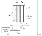
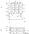
図1は、本実施の形態における燃料電池システム100の構成を示す図である。
燃料電池システム100は、燃料124を収容する容器142と、単位セル構造101と、容器142中に設けられた第三の電極140と、を有する。単位セル構造101は、基体104および燃料極側触媒層106により構成される燃料極102と、基体110および酸化剤極側触媒層112により構成される酸化剤極108と、燃料極102および酸化剤極108に狭持された固体電解質膜114と、を含む。第三の電極140は、燃料極102に対向して設けられる。
(First embodiment)
FIG. 1 is a diagram showing a configuration of a
The
また、燃料極102および第三の電極140にはそれぞれ、第一の引き出し線143aおよび第二の引き出し線143bが接続され、印加電圧制御部144は、第一の引き出し線143aおよび第二の引き出し線143bを介して燃料極102と第三の電極140との間に電圧を印加する。印加電圧制御部144は、たとえば電源とファンクションジェネレータとにより構成される。印加電圧制御部144が印加する電圧のプロファイルについては後述する。
The
燃料124は、たとえばメタノール、エタノール、ジメチルエーテル、または他のアルコール類、あるいはシクロパラフィン等の液体炭化水素等の液体燃料である。液体燃料は、水溶液とすることができる。
The
固体電解質膜114は、燃料極102と酸化剤極108を隔てるとともに、両者の間で水素イオンを移動させる役割を有する。このため、固体電解質膜114は、水素イオンの伝導性が高い膜であることが好ましい。また、化学的に安定であって機械的強度が高いことが好ましい。
The
燃料極102および第三の電極140の形状としては、燃料124に対する接触面積が大きく、また、燃料124の置換および拡散が行われやすい構造であることが好ましい。具体的には、メッシュ状電極、パンチング穴があいた板状電極、スポンジ状電極、多孔質電極等とすることができる。このような構造の電極を用いることにより、電極表面での反応を効率的に進行させることができる。
The shape of the
燃料極102および酸化剤極108は、それぞれ、触媒を担持した炭素粒子と固体電解質の微粒子とを含む燃料極側触媒層106および酸化剤極側触媒層112をそれぞれ基体104および基体110上に形成した構成とすることができる。
The
燃料極102としては、低抵抗であると同時に、耐腐食性に優れた材料を用いることが好ましい。具体的には、白金、金、銀、パラジウム、ルテニウム、イリジウム、ロジウム、レニウム、オスミウム、スズ、鉄、銅、ニッケル、コバルト、チタン、ジルコニウム、ステンレス、カーボンから選択される少なくとも1種または2種以上の材料、あるいはこれらの合金または酸化物が表面に露出した構成とすることができる。燃料極102の触媒としては、白金や白金とルテニウムの合金等を用いることができる。酸化剤極108および第三の電極140も、燃料極102と同様の材料により構成することができる。
As the
とくに、燃料極102の基体104としては、チタン等の表面にごく薄い導電性の酸化膜を形成して水を吸着しやすくする材料、ルテニウム、イリジウム、白金、ニッケル、またはコバルト等の酸素過電圧が低い材料、あるいは、ステンレス等の燃料124中での自然電位が大きい材料を用いることができる。これにより、燃料極102の耐酸化性を良好にすることができるとともに、燃料極102上でOHラジカルを効果的に生成させることができる。そのため、CO被毒に対して優れた防止効果が得られる。
In particular, as the
一方、第三の電極140としては、白金、金、銀等の比較的水素過電圧の低い材料を用いることができる。これにより、第三の電極140の耐還元性を良好にすることができるとともに、燃料極102での酸化反応を促進させることができる。酸化剤極108は、とくに限定されないが、たとえば第三の電極140と同様の材料により構成することができる。
On the other hand, the
本実施の形態において、燃料極102と対向する第三の電極140を設け、燃料極102と第三の電極140との間に電圧を印加するので、単位セル構造101の燃料電池回路への負荷を防ぐことができ、固体電解質膜114や燃料電池回路の損傷を防止することができる。また、このような第三の電極140を設けることにより、燃料極102に印加する消費電力を小さく抑えることもでき、投入エネルギーを少なくすることもできる。
In the present embodiment, since the
燃料極102と第三の電極140との間に効率よく電圧を印加するためには、燃料極102と第三の電極140との電極間距離は、狭い方が好ましい。燃料極102と第三の電極140との電極間距離は、好ましくは100mm以下、より好ましくは50mm以下とすることができる。これにより、電極間に生じる電界を強めることができ、より顕著な効果を得ることができる。
In order to efficiently apply a voltage between the
本実施の形態においては、燃料極102に所定の電位が印加されるのと同時に、第三の電極140には燃料極102とは逆の電位が印加される。このような電極への電位の変動により、第三の電極140においても、燃料124中の水に由来するラジカル種が発生する。このようなラジカル種の中には、酸化力の強いOHラジカルも含まれる。第三の電極140は、第三の電極140表面で発生したOHラジカル等のラジカル種が燃料極102まで拡散するような距離に配置されるのが好ましい。これにより、燃料極102に吸着したCOをより効率よく酸化することができる。
In the present embodiment, at the same time as a predetermined potential is applied to the
また、電極間距離の下限は、とくに制限はないが、好ましくは50μm以上、より好ましくは100μm以上とすることができる。 The lower limit of the distance between the electrodes is not particularly limited, but is preferably 50 μm or more, more preferably 100 μm or more.
本実施の形態において、燃料極102と第三の電極140との間には、電気伝導性領域が設けられることが好ましい。これにより、第三の電極140と燃料極102との間に電圧を印加した際に、これらの電極間の電気化学反応が進行しやすくなり、燃料極102および燃料極側触媒層106でのCO被毒の防止および酸化被膜形成防止の効果が、より顕著に得られるとともに、電極間の溶液抵抗から生じる電気的ロスを低減することができる。
In the present embodiment, it is preferable that an electrically conductive region is provided between the
電気伝導性領域は、たとえば燃料124中に電解質を添加することにより実現することができる。電解質としては、金属カチオンを含まないものが好ましく、具体的には、硫酸や炭酸などの無機酸、アスコルビン酸やクエン酸などの有機酸、水酸化テトラメチルアンモニウムなどの有機アルカリなどを用いることができる。また、第三の電極140と燃料極102との間に電解質膜等のシートを挟持させることにより、電極間に電気伝導性領域を設けることもできる。
The electrically conductive region can be realized by adding an electrolyte to the
次に、印加電圧制御部144が燃料極102と第三の電極140との間に、印加する電圧のプロファイルについて説明する。
Next, a profile of a voltage applied by the applied
印加電圧制御部144は、燃料極102におけるCO被毒を抑制することができる、比較的高い第一の電位と、燃料極102における酸化被膜の形成を抑制することができる比較的低い第二の電位とを交互に燃料極102に印加する。
The applied
第一の電位は、たとえば、0.3V(銀/塩化銀電極基準)以上とすることができる。0.3V以上の電位を印加することにより、燃料極102においてOHラジカルが生じはじめ、Pt−COが酸化されはじめる。これにより、燃料極側触媒層106のCOがCO2に酸化され、CO被毒を低減することができる。また、第一の電位は、たとえば、1V(銀/塩化銀電極基準)以下とすることができる。電位の上限をこの程度にすることにより、燃料極102の燃料極側触媒層106が、Pt−OHやPt−O等の酸化被膜で覆われてしまうのを防ぐことができ、燃料極側触媒層106の触媒表面の酸化による触媒作用の低下および燃料124の酸化反応の抑制を防ぐことができる。
The first potential can be, for example, 0.3 V (silver / silver chloride electrode reference) or more. By applying a potential of 0.3 V or more, OH radicals begin to be generated in the
第二の電位は、たとえば、0.6V(銀/塩化銀電極基準)以下とすることができる。0.6V以下の電位を印加することにより、燃料極102において、酸化被膜のPt−OHやPt−Oが還元されはじめる。また、第二の電位は、たとえば、−0.3V(銀/塩化銀電極基準)以上とすることができる。第二の電位の下限をこの程度にすることにより、燃料極102において、燃料極102が水素で覆われ、水素が発生する現象を防ぐことができる。これにより、電力効率を良好に保つことができる。
The second potential can be, for example, 0.6 V (silver / silver chloride electrode reference) or less. By applying a potential of 0.6 V or less, Pt—OH or Pt—O of the oxide film starts to be reduced at the
第一の電位と第二の電位との電位差は、たとえば0.01V以上2V以下とすることができる。電位差の下限をこの程度とすることにより、CO被毒の低減および酸化被膜の抑制を実効的に行うことができる。また、電位差の上限をこの程度とすることにより、固体電解質膜114や燃料電池回路へダメージを与えることなく、燃料電池の出力を向上することができる。
The potential difference between the first potential and the second potential can be, for example, 0.01 V or more and 2 V or less. By setting the lower limit of the potential difference to this level, it is possible to effectively reduce CO poisoning and suppress the oxide film. Further, by setting the upper limit of the potential difference to this level, the output of the fuel cell can be improved without damaging the
なお、交流電圧の印加の際に、直流オフセット電圧を加えて印加することも可能である。これにより、任意の基準電位に対して、燃料極102の電位を、当該基準電位よりも高くしたり低くしたりすることができ、また、それぞれの変動電位の大きさや保持時間を制御したりすることが可能であるため、特定の電位で進行するような反応を集中的に促進させる場合などに特に有効である。
In addition, it is also possible to apply and apply a DC offset voltage when applying an AC voltage. Thereby, the potential of the
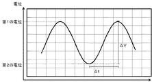
図2は、燃料極102および第三の電極140間に印加する電圧の一例を示す図である。印加電圧制御部144は、燃料極102に、図示したような正弦波の交流電圧を印加することができる。ここで、交流電圧とは、時間と共に電圧(または電流値)および電流の向きの少なくともいずれかが変化する電圧のことをいう。燃料極102に交流電圧が印加されると、燃料極102の燃料極側触媒層106において触媒の電位が変動し、触媒表面で、酸化と還元が交互に進行する。その結果、触媒表面が活性化されるとともに、触媒表面の酸化が防止される。
FIG. 2 is a diagram illustrating an example of a voltage applied between the
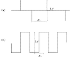
また、印加電圧制御部144は、燃料極102および第三の電極140間に図3に示したような電圧を印加することもできる。図3(a)は、燃料極102および第三の電極140間に第一の電位および第二の電位のパルス波を印加する例を示す図である。また、図3(b)は、燃料極102および第三の電極140間に、矩形波を印加する例を示す図である。
The applied
印加電圧制御部144は、図2および図3に示したプロファイル以外でも、三角波、台形波、階段波、または任意に作成した定常波を印加することができる。これらの中でも、単位周期において電位変化速度が任意に制御可能な正弦波、三角波、台形波などを選択することにより、より効果的な電位制御が可能となる。
The applied
次に、図2および図3を参照して、第一の電位と第二の電位を印加する時間の間隔を説明する。 Next, with reference to FIG. 2 and FIG. 3, the time interval for applying the first potential and the second potential will be described.
第一の電位と第二の電位とを印加する時間の間隔Δtは、
0.005≦|ΔV|/Δt≦50
となるように制御されることが好ましい。ここで、ΔVは、第一の電位と第二の電位の差である。
The time interval Δt for applying the first potential and the second potential is:
0.005 ≦ | ΔV | / Δt ≦ 50
It is preferable to be controlled so that Here, ΔV is the difference between the first potential and the second potential.
より好ましくは、第一の電位と第二の電位とを印加する時間の間隔Δtは、
0.01≦(|ΔV|/Δt)≦10
となるように制御されることが好ましい。
More preferably, the time interval Δt for applying the first potential and the second potential is:
0.01 ≦ (| ΔV | / Δt) ≦ 10
It is preferable to be controlled so that
燃料極102において、CO被膜を低減するためには、燃料極102でOHラジカルを生じさせる必要があるが、第一の電位と第二の電位を印加する時間間隔を短くしすぎると、電極表面における反応物質の供給や拡散が電位の変化に追いつかず、OHラジカルの発生やPt−OHの還元が効率よく行われない。時間の間隔Δtを上記のような範囲とすることにより、OHラジカルの発生やPt−OHの還元を効率よく行うことができる。
In order to reduce the CO coating at the
一方、第一の電位と第二の電位を印加する時間間隔が長すぎると、その間に電極表面の反応が飽和してしまい、反応が進まなくなり、電力的なロスが生じてしまう。時間の間隔Δtを上記のような範囲とすることにより、電力的なロスが生じることなく、OHラジカルの発生やPt−OHの還元を効率よく行うことができる。 On the other hand, if the time interval for applying the first potential and the second potential is too long, the reaction on the electrode surface is saturated during that time, the reaction does not proceed, and power loss occurs. By setting the time interval Δt in the above range, it is possible to efficiently generate OH radicals and reduce Pt—OH without causing power loss.
以上のように、本実施の形態における燃料電池システム100によれば、第三の電極140を設けて第三の電極140と燃料極102との間に電圧を印加しているので、単位セル構造101自体の電位に影響することがない。これにより、固体電解質膜114や単位セル構造101が損傷を受けるおそれもなく、CO被毒や酸化被膜の生成を抑制することができる。
As described above, according to the
(第二の実施の形態)
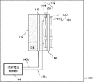
図4は、本実施の形態における燃料電池システム100の構成を示す図である。
本実施の形態において、燃料電池システム100は、複数の燃料極102および酸化剤極108を有し、これら複数の燃料極102および酸化剤極108は、一つの固体電解質膜114を共有し、それぞれ対向して設けられている。
(Second embodiment)
FIG. 4 is a diagram showing a configuration of the
In the present embodiment, the
また、本実施の形態においても、燃料電池システム100は、第三の電極140を含む。第三の電極140は、複数の燃料極102に共有して設けられる。これにより、簡易な構成で複数の燃料極102のCO被毒の防止および酸化被膜の抑制を行うことができる。
Also in the present embodiment, the
図5(a)は、本実施の形態における燃料電池システム100を示す上面図である。図5(b)は、図5(a)のA−A’断面図である。ここでは、単位セル構造101が形成された部分だけを示す。
FIG. 5A is a top view showing the
ここで、燃料電池システム100は、複数の単位セル構造101と、容器142と、容器142に燃料124を供給するとともに、容器142を循環した燃料124を回収する燃料タンク851とを含む。容器142と燃料タンク851とは、燃料通路854および燃料通路855を介して連結される。容器142内には複数の仕切り板853が設けられ、液体流路が形成されている。
Here, the
本実施の形態において、容器142には、燃料通路854を介して燃料124供給される。ここで図示していないが、燃料通路854には燃料124を巡回させるポンプが設けられる。燃料124は、容器142内に設けられた複数の仕切り板853に沿って流れ、複数の単位セル構造101に順次供給される。複数の単位セル構造101を循環した燃料は、燃料通路855を介して燃料タンク851に回収される。
In the present embodiment, the
尚、燃料タンク851は、容器142を含む燃料電池システム100本体と着脱可能に構成されたカートリッジとすることもできる。
The
以下、実施例を参照して本発明をさらに詳細に説明するが、本発明はこれらの実施例に限定されるものではない。 EXAMPLES Hereinafter, although this invention is demonstrated further in detail with reference to an Example, this invention is not limited to these Examples.
(実施例1)
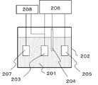
図6に示した構成の3電極式の電解セルを用いることにより、図1に示した燃料電池システム100における燃料極102の反応を模擬的に進行させ、交流電圧印加によるメタノール酸化反応の促進を検討した。
(Example 1)
By using the three-electrode electrolytic cell having the configuration shown in FIG. 6, the reaction of the
本実施例の電解セルは、作用極203、対極204、参照極205、および対向電極207を含む。これらの電極を、反応溶液201を収容した容器202内に収容した。作用極203および対極204としては、Pt板(たて15mm、よこ10mm、厚さ0.01mm)を用い、参照極205としては飽和KCl銀塩化銀タイプのガラス電極を用いた。作用極203、対極204、および参照極205をポテンショスタット206に接続し、作用極203の表面で生じた電気化学反応を解析するようにした。また、対向電極207および作用極203をファンクションジェネレータ208に接続し、これらの電極間に交流電圧を印加できるようにした。ここで、対向電極207と作用極203との電極間距離は5mmとした。反応溶液201としては、メタノール濃度3質量%、硫酸濃度8質量%の水溶液を用いた。硫酸は、反応溶液の電気伝導度を確保するための電解質として機能する。
The electrolysis cell of this example includes a working
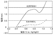
まず、作用極203上でのメタノールの酸化を進行させるため、ポテンショスタット206により、作用極203の電位を、自然電位(0.4V付近)から1.2Vまで、電位掃引速度50mV/secで走査した。さらに、ファンクションジェネレータ208を用いて、作用極203と対向電極207の間に、周波数10Hz、振幅0.05Vの正弦波の交流電圧を印加し、作用極203の電位を変動させた(交流印加に基づく電位変動速度は2V/secとした)。これにより、作用極203の電位は、ポテンショスタット206による直流電圧に加え、ファンクションジェネレータ208による交流電圧が混成された状態とした。なお、本実施例の方法においては、ポテンショスタット206自体の有する電位制御機能のため、ファンクションジェネレータ208で印加した交流電圧が、実際の作用極203の電位変動(たとえば波形など)と若干ずれる可能性があり、これは実験上の回避できない問題として含まれるものである。
First, in order to advance the oxidation of methanol on the working
図7に、上記の方法で作用極203の電位を制御した場合の酸化電流の特性を示す。交流電圧を印加しなかった通常の反応に比べて、交流電圧を印加した場合、酸化電流の著しい増加が認められた。これにより、交流電圧印加によるメタノール酸化の促進が確かめられた。また、対向電極207と作用極203との間に流れる電流を測定したところ、約0.1mA程度の交流電流だった。このように、対向電極207を設けて交流電圧を印加しても、消費電力量は極めて少ないことが確かめられた。
FIG. 7 shows the characteristics of the oxidation current when the potential of the working
(実施例2)
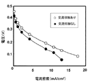
本実施例では、図1に示した燃料電池システム100を用いて交流電圧印加による出力の増加を検討した。
(Example 2)
In this example, an increase in output due to application of an AC voltage was examined using the
燃料124としては、メタノール濃度が3質量%、硫酸濃度が8質量%の水溶液を用いた。燃料極102は、Ti板からなる基体104と、Pt−Ru系触媒とこれを担持したカーボンブラック層からなる燃料極側触媒層106とにより構成した。固体電解質膜114としては、ナフィオン(登録商標)117を用いた。燃料極側触媒層106の有効面積は9cm2であった。第三の電極140としては、PtメッキされたTi板を用い、燃料124が通過できるようにパンチング穴をあけた構造とした。
As the
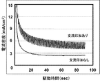
以上のように構成された燃料電池システム100の燃料極102と第三の電極140との間に、振幅0.25V、周波数1Hzの交流電圧(交流印加に基づく電位変動速度は1V/sec)を印加した場合の出力特性を、ガルバノスタット(不図示)により測定した。その結果を図8に示す。
Between the
交流を印加しなかった場合に比べて、上記交流を印加した場合、出力が増加することが示された。 It was shown that the output increased when the alternating current was applied compared to when no alternating current was applied.
(実施例3)
本実施例でも、図1に示した燃料電池システム100を用いて、所定の電気負荷を与え、定電位で駆動させた場合の、セル電流の時間変化について調べた。本実施例において、固体電解質膜114としてはナフィオン(登録商標)112を用いた以外は実施例2と同様にした。
(Example 3)
Also in this example, the time variation of the cell current when the
本実施例では、ポテンショスタットを用いて、本燃料電池システムの平均セル電圧が0.35Vとなるように電気負荷を与え、出力電流の時間変化を調べた。その結果を、図9に示す。 In this example, using a potentiostat, an electric load was applied so that the average cell voltage of the fuel cell system was 0.35 V, and the time change of the output current was examined. The result is shown in FIG.
交流を印加しなかった通常の場合に比べて、本実施例のシステムでは、出力電流の増加が認められた。ここでは、燃料極102の電位変動に伴う出力電流の変動が認められているが、いずれの場合でも、交流を印加しなかった場合に比べて、出力電流が増加した。
In the system of this example, an increase in output current was observed compared to a normal case where no alternating current was applied. Here, fluctuations in the output current due to fluctuations in the potential of the
(実施例4)
本実施例では、第三の電極140を構成する材料を異ならせた場合の燃料電池の出力を調べた。
Example 4
In this example, the output of the fuel cell when the material constituting the
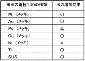
ここでは、第三の電極140を構成する材料としては、Pt、Au、Pd、Cu、Ni、Ti、およびSUSを用いた。燃料極102は、Ti板からなる基体104と、Pt−Ru系触媒とこれを担持したカーボンブラック層からなる燃料極側触媒層106とにより構成した。
Here, Pt, Au, Pd, Cu, Ni, Ti, and SUS were used as the material constituting the
その結果を図10に示す。図中、○は「効果が認められる」、△は「わずかに効果が認められる」、×は「ほとんど効果が認められない」という結果を示す。図10に示すように、第三の電極140をPtやAu等、水素過電圧の低い材料により構成した場合、燃料電池システム100の出力が増加した。一方、第三の電極140をNiやPd等、水素過電圧の大きな材料により構成した場合、燃料電池システム100の出力の向上はあまり見られなかった。これは、水素過電圧の大きな材料を第三の電極140に用いると、第三の電極140で水の還元反応が起こりにくくなり、そのため、対極の関係にある燃料極102で水の酸化反応が起こりにくくなるためと考えられる。このため、燃料極102の表面でのOHラジカル等のラジカル種の発生が抑えられ、CO被毒防止効果が低下したためと考えられる。
The result is shown in FIG. In the figure, ◯ indicates the result that “effect is recognized”, Δ indicates “slightly effect”, and × indicates “almost no effect”. As shown in FIG. 10, when the
以上、本発明を実施の形態および実施例に基づいて説明した。この実施の形態および実施例はあくまで例示であり、種々の変形例が可能なこと、またそうした変形例も本発明の範囲にあることは当業者に理解されるところである。 The present invention has been described based on the embodiments and examples. It is to be understood by those skilled in the art that the embodiments and examples are merely examples, and various modifications are possible and that such modifications are within the scope of the present invention.
以上の実施の形態では、燃料として液体燃料を用いた直接型の燃料電池システムについて説明したが、本発明は、電極においてCO被毒や酸化被膜が生じるような燃料を用いた種々の燃料電池に適用することができる。 In the above embodiment, the direct type fuel cell system using liquid fuel as the fuel has been described. However, the present invention is applicable to various fuel cells using fuel that causes CO poisoning and oxide film on the electrode. Can be applied.
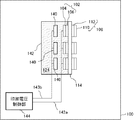
以上の第二の実施の形態において、一つの第三の電極140が複数の燃料極102に共有して設けられた形態を示したが、図12に示すように、燃料電池システム100は、複数の第三の電極140を含み、各燃料極102にそれぞれ第三の電極140が設けられた構成とすることもできる。
In the second embodiment described above, the configuration in which one
100 燃料電池システム
101 単位セル構造
102 燃料極
104 基体
106 燃料極側触媒層
108 酸化剤極
110 基体
112 酸化剤極側触媒層
114 固体電解質膜
124 燃料
126 酸化剤
140 第三の電極
142 容器
143a 第一の引き出し線
143b 第二の引き出し線
144 印加電圧制御部
100
Claims (14)
前記第一の電極に離隔して設けられた第三の電極と、
前記第一の電極と前記第三の電極との間に電圧を印加する電圧印加手段と、
を含むことを特徴とする燃料電池システム。 A unit cell comprising: a first electrode to which liquid fuel is supplied; a second electrode to which an oxidant is supplied; and an electrolyte membrane sandwiched between them;
A third electrode spaced apart from the first electrode;
Voltage applying means for applying a voltage between the first electrode and the third electrode;
A fuel cell system comprising:
前記第一の電極に配して設けられ、前記液体燃料が満たされた燃料供給系をさらに含み、
前記第三の電極は、前記燃料供給系内に設けられたことを特徴とする燃料電池システム。 The fuel cell system according to claim 1, wherein
A fuel supply system disposed on the first electrode and filled with the liquid fuel;
The fuel cell system, wherein the third electrode is provided in the fuel supply system.
前記電圧印加手段は、第一の電位と、前記第一の電位よりも低い第二の電位とを交互に印加することを特徴とする燃料電池システム。 The fuel cell system according to claim 1 or 2,
The fuel cell system, wherein the voltage applying means alternately applies a first potential and a second potential lower than the first potential.
前記第二の電位は、前記第一の電極周囲の前記液体燃料中でHラジカルが生じる電位であることを特徴とする燃料電池システム。 The fuel cell system according to claim 3, wherein
The fuel cell system according to claim 1, wherein the second potential is a potential at which H radicals are generated in the liquid fuel around the first electrode.
前記電圧印加手段は、前記第一の電位および前記第二の電位をそれぞれピークとする交流電圧を印加することを特徴とする燃料電池システム。 The fuel cell system according to claim 3 or 4,
The fuel cell system, wherein the voltage applying means applies an AC voltage having the first potential and the second potential as peaks.
前記第一の電位と前記第二の電位の電位差は、0.01V以上であることを特徴とする燃料電池システム。 The fuel cell system according to any one of claims 3 to 5,
The fuel cell system, wherein a potential difference between the first potential and the second potential is 0.01 V or more.
前記電圧印加手段は、前記第一の電位と前記第二の電位とを、下記の一般式で表される間隔Δtで印加することを特徴とする燃料電池システム。
0.005≦|ΔV|/Δt≦50
(ここで、ΔVは第一の電位と第二の電位との差を示す。) The fuel cell system according to any one of claims 3 to 6,
The fuel cell system, wherein the voltage applying means applies the first potential and the second potential at an interval Δt represented by the following general formula.
0.005 ≦ | ΔV | / Δt ≦ 50
(Here, ΔV represents the difference between the first potential and the second potential.)
前記第三の電極は、前記第一の電極に対向して設けられたことを特徴とする燃料電池システム。 The fuel cell system according to any one of claims 1 to 7,
The fuel cell system, wherein the third electrode is provided to face the first electrode.
前記第三の電極は、前記第一の電極に略平行に設けられ、
前記第一の電極と前記第三の電極との電極間距離は、100mm以下であることを特徴とする燃料電池システム。 The fuel cell system according to claim 8, wherein
The third electrode is provided substantially parallel to the first electrode,
An inter-electrode distance between the first electrode and the third electrode is 100 mm or less.
前記第一の電極と前記第三の電極との間には、電気伝導性領域が設けられたことを特徴とする燃料電池システム。 The fuel cell system according to any one of claims 1 to 9,
A fuel cell system, wherein an electrically conductive region is provided between the first electrode and the third electrode.
前記第一の電極は、触媒としてPtを含むことを特徴とする燃料電池システム。 The fuel cell system according to any one of claims 1 to 10,
The fuel cell system, wherein the first electrode includes Pt as a catalyst.
平面状に配置された複数の前記単位セルを含むことを特徴とする燃料電池システム。 The fuel cell system according to any one of claims 1 to 11,
A fuel cell system comprising a plurality of the unit cells arranged in a plane.
平面状に配置された複数の前記単位セルを含み、
前記第三の電極は、少なくとも2以上の前記単位セルの前記第一の電極に共有で設けられたことを特徴とする燃料電池システム。 The fuel cell system according to any one of claims 1 to 11,
Including a plurality of the unit cells arranged in a plane;
The fuel cell system, wherein the third electrode is shared by the first electrodes of at least two or more unit cells.
前記第一の電極と前記第二の電極との間で電気化学反応を行っている間に、前記第一の電極と前記第三の電極との間に電圧を印加する工程を含むことを特徴とする燃料電池システムの駆動方法。
A fuel cell comprising a first electrode to which liquid fuel is supplied, a second electrode to which oxidant is supplied, and an electrolyte membrane sandwiched therebetween, and a third electrode provided in the liquid fuel A method for driving a fuel cell system, comprising:
A step of applying a voltage between the first electrode and the third electrode during an electrochemical reaction between the first electrode and the second electrode. A driving method of a fuel cell system.
Priority Applications (1)
| Application Number | Priority Date | Filing Date | Title |
|---|---|---|---|
| JP2004103939A JP2005293901A (en) | 2004-03-31 | 2004-03-31 | Fuel cell system and driving method thereof |
Applications Claiming Priority (1)
| Application Number | Priority Date | Filing Date | Title |
|---|---|---|---|
| JP2004103939A JP2005293901A (en) | 2004-03-31 | 2004-03-31 | Fuel cell system and driving method thereof |
Publications (1)
| Publication Number | Publication Date |
|---|---|
| JP2005293901A true JP2005293901A (en) | 2005-10-20 |
Family
ID=35326623
Family Applications (1)
| Application Number | Title | Priority Date | Filing Date |
|---|---|---|---|
| JP2004103939A Pending JP2005293901A (en) | 2004-03-31 | 2004-03-31 | Fuel cell system and driving method thereof |
Country Status (1)
| Country | Link |
|---|---|
| JP (1) | JP2005293901A (en) |
Cited By (8)
| Publication number | Priority date | Publication date | Assignee | Title |
|---|---|---|---|---|
| JP2007123208A (en) * | 2005-10-31 | 2007-05-17 | Toshiba Corp | Fuel cell system and fuel cell output improvement method |
| JP2008293781A (en) * | 2007-05-24 | 2008-12-04 | Yokogawa Electric Corp | Performance evaluation method and performance evaluation apparatus |
| WO2009093651A1 (en) * | 2008-01-23 | 2009-07-30 | Nec Corporation | Fuel cell and control method for same |
| JP2014056750A (en) * | 2012-09-13 | 2014-03-27 | Hitachi Zosen Corp | Activation method of alkaline fuel cell |
| JP2015111574A (en) * | 2006-03-02 | 2015-06-18 | エンサイト・エルエルシーEncite Llc | Method and apparatus for cleaning catalyst of power cell |
| US9406955B2 (en) | 1999-11-24 | 2016-08-02 | Encite Llc | Methods of operating fuel cells |
| US9819037B2 (en) | 2006-03-02 | 2017-11-14 | Encite Llc | Method and apparatus for cleaning catalyst of a power cell |
| JP2018154900A (en) * | 2017-03-21 | 2018-10-04 | 株式会社東芝 | Electrochemical reaction apparatus and electrochemical reaction method |
-
2004
- 2004-03-31 JP JP2004103939A patent/JP2005293901A/en active Pending
Cited By (11)
| Publication number | Priority date | Publication date | Assignee | Title |
|---|---|---|---|---|
| US9406955B2 (en) | 1999-11-24 | 2016-08-02 | Encite Llc | Methods of operating fuel cells |
| JP2007123208A (en) * | 2005-10-31 | 2007-05-17 | Toshiba Corp | Fuel cell system and fuel cell output improvement method |
| JP2015111574A (en) * | 2006-03-02 | 2015-06-18 | エンサイト・エルエルシーEncite Llc | Method and apparatus for cleaning catalyst of power cell |
| US9819037B2 (en) | 2006-03-02 | 2017-11-14 | Encite Llc | Method and apparatus for cleaning catalyst of a power cell |
| US10199671B2 (en) | 2006-03-02 | 2019-02-05 | Encite Llc | Apparatus for cleaning catalyst of a power cell |
| US11121389B2 (en) | 2006-03-02 | 2021-09-14 | Encite Llc | Method and controller for operating power cells using multiple layers of control |
| JP2008293781A (en) * | 2007-05-24 | 2008-12-04 | Yokogawa Electric Corp | Performance evaluation method and performance evaluation apparatus |
| WO2009093651A1 (en) * | 2008-01-23 | 2009-07-30 | Nec Corporation | Fuel cell and control method for same |
| JP2014056750A (en) * | 2012-09-13 | 2014-03-27 | Hitachi Zosen Corp | Activation method of alkaline fuel cell |
| JP2018154900A (en) * | 2017-03-21 | 2018-10-04 | 株式会社東芝 | Electrochemical reaction apparatus and electrochemical reaction method |
| CN108624906A (en) * | 2017-03-21 | 2018-10-09 | 株式会社东芝 | Electrochemical reaction appts and electrochemical reaction method |
Similar Documents
| Publication | Publication Date | Title |
|---|---|---|
| Amendola et al. | A novel high power density borohydride-air cell | |
| US10612147B2 (en) | Electrochemical reaction device and electrochemical reaction method | |
| JP2018123390A (en) | Electrolytic cell of carbon dioxide and electrolytic apparatus | |
| Yang et al. | Nickel and cobalt electrodeposited on carbon fiber cloth as the anode of direct hydrogen peroxide fuel cell | |
| Zhiani et al. | Performance study of passive and active direct borohydride fuel cell employing a commercial Pd decorated Ni–Co/C anode catalyst | |
| JP7036316B2 (en) | Electrochemical devices and methods for controlling electrochemical devices | |
| US20250263853A1 (en) | Organic hydride generation system, control device for organic hydride generation system, and control method for organic hydride generation system | |
| US20250179660A1 (en) | Method for controlling organic hydride generation system, and organic hydride generation system | |
| JP2005293901A (en) | Fuel cell system and driving method thereof | |
| EP2575204A1 (en) | Fuel battery system | |
| JPWO2014208019A1 (en) | Methanol generating apparatus, method for generating methanol, and electrode for methanol generation | |
| JP4601647B2 (en) | Hydrogen generator and fuel cell system using the same | |
| JP6200475B2 (en) | System and method for electrochemical reduction of carbon dioxide | |
| JP5618485B2 (en) | Electrochemical cell operation method | |
| KR20140133301A (en) | The membrane electrdoe assembly for an electrochemical cell | |
| Varhade et al. | An inherent heat driven fuel exhaling hydrazine fuel cell | |
| JP2019218579A (en) | Chemical reaction device, and solar energy utilization system using the same | |
| JP7038375B2 (en) | Electrochemical devices and methods for controlling electrochemical devices | |
| Yamazaki et al. | Controllable electrochemical generation of H2 from hydrazine together with slight power generation using a membraneless cell | |
| JP2024142503A (en) | How to start up the electrolysis cell | |
| CN110678580B (en) | Hydrogen generator and hydrogen generating method | |
| WO2022250119A1 (en) | Catalyst, method for producing catalyst, and intermediate product | |
| Pan | Investigations on direct ethylene glycol fuel cells using hydrogen peroxide as oxidant | |
| CN103492616A (en) | Coating for metallic cell-element materials of an electrolytic cell | |
| JP2005347066A (en) | Catalyst electrode manufacturing method, catalyst electrode, electrochemical element, fuel cell, and electronic device |