JP6200312B2 - Control device for electric motor for vehicle - Google Patents
Control device for electric motor for vehicle Download PDFInfo
- Publication number
- JP6200312B2 JP6200312B2 JP2013265231A JP2013265231A JP6200312B2 JP 6200312 B2 JP6200312 B2 JP 6200312B2 JP 2013265231 A JP2013265231 A JP 2013265231A JP 2013265231 A JP2013265231 A JP 2013265231A JP 6200312 B2 JP6200312 B2 JP 6200312B2
- Authority
- JP
- Japan
- Prior art keywords
- motor
- vehicle
- braking
- value
- driving force
- Prior art date
- Legal status (The legal status is an assumption and is not a legal conclusion. Google has not performed a legal analysis and makes no representation as to the accuracy of the status listed.)
- Active
Links
Images


Classifications
-
- Y—GENERAL TAGGING OF NEW TECHNOLOGICAL DEVELOPMENTS; GENERAL TAGGING OF CROSS-SECTIONAL TECHNOLOGIES SPANNING OVER SEVERAL SECTIONS OF THE IPC; TECHNICAL SUBJECTS COVERED BY FORMER USPC CROSS-REFERENCE ART COLLECTIONS [XRACs] AND DIGESTS
- Y02—TECHNOLOGIES OR APPLICATIONS FOR MITIGATION OR ADAPTATION AGAINST CLIMATE CHANGE
- Y02T—CLIMATE CHANGE MITIGATION TECHNOLOGIES RELATED TO TRANSPORTATION
- Y02T10/00—Road transport of goods or passengers
- Y02T10/60—Other road transportation technologies with climate change mitigation effect
- Y02T10/64—Electric machine technologies in electromobility
-
- Y—GENERAL TAGGING OF NEW TECHNOLOGICAL DEVELOPMENTS; GENERAL TAGGING OF CROSS-SECTIONAL TECHNOLOGIES SPANNING OVER SEVERAL SECTIONS OF THE IPC; TECHNICAL SUBJECTS COVERED BY FORMER USPC CROSS-REFERENCE ART COLLECTIONS [XRACs] AND DIGESTS
- Y02—TECHNOLOGIES OR APPLICATIONS FOR MITIGATION OR ADAPTATION AGAINST CLIMATE CHANGE
- Y02T—CLIMATE CHANGE MITIGATION TECHNOLOGIES RELATED TO TRANSPORTATION
- Y02T10/00—Road transport of goods or passengers
- Y02T10/60—Other road transportation technologies with climate change mitigation effect
- Y02T10/72—Electric energy management in electromobility
Description
本発明は、車両に搭載され、互いに噛み合う複数のギヤを有する動力伝達系を介して、車輪を駆動又は制動する発電可能な電動機を制御する車両用電動機の制御装置に関する。 The present invention relates to a control device for a vehicular motor that controls a motor capable of generating electricity that drives or brakes wheels via a power transmission system that is mounted on a vehicle and has a plurality of gears that mesh with each other.
従来、電動機と、電動機で駆動される負荷と、電動機及び負荷を互いに連結する軸とによって構成されるねじり系を制御対象として、振動を抑制するための制御方式が、例えば特許文献1に記載されている。この制御方式では、電動機速度、ねじりトルク及び負荷速度などの制御対象の内部状態変数に状態フィードバックゲインを乗算することで、状態フィードバック制御系を構成するとともに、速度指令値と負荷速度との差に積分要素を入れて、状態フィードバック速度制御系を構成する。
Conventionally, for example,
また、電動機の入力指令と電動機速度から等価外乱オブザーバを構成し、制御対象の入力である外乱トルクを推定する。このように外乱トルクを推定することにより、負荷速度やねじりトルクを推定することが可能になり、それらの検出器が不要になることで、制御系の構成の簡素化やコストの低減を図りながら、ねじり系の振動を抑制することが可能になる。 Further, an equivalent disturbance observer is constructed from the motor input command and the motor speed, and the disturbance torque that is the input to be controlled is estimated. By estimating the disturbance torque in this way, it becomes possible to estimate the load speed and torsional torque, eliminating the need for those detectors, while simplifying the control system configuration and reducing costs. It becomes possible to suppress the vibration of the torsion system.
しかし、以下に述べるように、この従来の制御方式では、例えば、車両の車輪が、複数のギヤを有する動力伝達系を介して、電動機で駆動又は制動される場合には、振動などの不具合を有効に抑制できないという問題がある。すなわち、このような車両では、電動機による車輪の駆動/制動状態が切り替わるときに、動力伝達系の複数のギヤ間に存在するバックラッシュの詰まりが発生する。そして、このバックラッシュ詰まりが終了するまでの間、電動機と車輪との機械的な連結が解かれ、両者間でトルクが伝達されないため、電動機の回転速度が急激に変動する。 However, as described below, in this conventional control method, for example, when a vehicle wheel is driven or braked by an electric motor via a power transmission system having a plurality of gears, problems such as vibrations are caused. There is a problem that it cannot be effectively suppressed. That is, in such a vehicle, when the driving / braking state of the wheel by the electric motor is switched, clogging of backlash existing between a plurality of gears of the power transmission system occurs. Until the backlash clogging is completed, the mechanical connection between the electric motor and the wheel is released, and torque is not transmitted between the two, so that the rotational speed of the electric motor changes rapidly.
このため、バックラッシュ詰まりの終了時に、電動機の回転速度が大きく変動した状態で、車輪との間のトルク伝達が再開される結果、それに起因するショックや異音、振動が発生するおそれがある。これに対し、上述した従来の制御方式では、電動機と負荷の間をギヤをもたない軸で単に連結したねじり系を制御対象として、その振動を抑制するにすぎないので、ギヤのバックラッシュ詰まりに起因する上述した不具合を抑制することはできない。 For this reason, at the end of backlash clogging, torque transmission with the wheel is resumed in a state where the rotational speed of the motor has greatly fluctuated, and as a result, there is a risk that shock, abnormal noise, or vibration will occur. On the other hand, in the above-described conventional control method, a torsion system in which the motor and the load are simply connected by a shaft having no gear is controlled, and the vibration is only suppressed. It is impossible to suppress the above-described problems caused by the above.
本発明は、このような課題を解決するためになされたものであり、電動機による車輪の駆動/制動状態の切替時におけるギヤのバックラッシュ詰まりに起因するショックや異音、振動などの不具合を抑制することができる車両用電動機の制御装置を提供することを目的とする。 The present invention has been made to solve such problems, and suppresses problems such as shock, abnormal noise, and vibration caused by a backlash clogging of a gear at the time of driving / braking state switching of a wheel by an electric motor. It is an object of the present invention to provide a control device for a vehicular electric motor.
上記の目的を達成するために、本願の請求項1に係る発明は、互いに噛み合う複数のギヤ(実施形態における(以下、本項において同じ)第1サンギヤ52、2連ピニオンギヤ54及び第1リングギヤ53、第2サンギヤ72、2連ピニオンギヤ74及び第2リングギヤ73)を有する動力伝達系を介して車両(ハイブリッド車両V)の車輪(左後輪WRL、右後輪WRR)に機械的に連結され、動力伝達系を介して車輪を駆動又は制動する発電可能な電動機(第1リヤモータ41、第2リヤモータ61)を制御する車両用電動機の制御装置であって、動力伝達系よりも電動機側である所定の第1位置における回転速度を表す第1回転速度パラメータ(モータ回転数NMOTL、NMOTR)を取得する第1回転速度パラメータ取得手段(モータ回転数センサ102a、102b)と、動力伝達系よりも車輪側である所定の第2位置における回転速度を表す第2回転速度パラメータ(車輪回転数NWRL、NWRR)を取得する第2回転速度パラメータ取得手段(車輪回転数センサ101c、101d)と、取得された第1及び第2回転速度パラメータの一方を基準値とし、第1及び第2回転速度パラメータの他方を、複数のギヤのギヤ比RGに基づき、基準値を基準として換算した換算値(後輪回転数換算値NWCONV)を算出する換算値算出手段(ECU2、図7のステップ4)と、車輪を駆動又は制動する電動機の制駆動力(モータ要求トルクTRREQ)を取得する制駆動力取得手段(ECU2、図7のステップ1)と、取得された電動機の制駆動力に基づき、第1位置と第2位置との間における動力伝達系のねじれ分に相当する回転速度パラメータを、ねじれ分相当値(ねじれ分回転数NTOR)として算出するねじれ分相当値算出手段(ECU2、図7のステッ2プ)と、基準値と算出された換算値との乖離度合(モータ回転数NMOTL−後輪回転数換算値NWCONV)、及び算出されたねじれ分相当値に基づいて、電動機を制御する電動機制御手段(ECU2、図7のステップ9)と を備え、電動機制御手段は、車両の運転状態に基づいて、電動機に要求される要求制駆動力(モータ要求トルクTRREQ)を算出する要求制駆動力算出手段(ECU2、図7のステップ1)と、算出された要求制駆動力を、乖離度合及びねじれ分相当値に基づき、乖離度合が減少するように補正することによって、電動機の目標制駆動力(目標トルクTROBJ)を設定する補正手段(ECU2、図7のステップ8、9)と、を有し、補正手段は、要求制駆動力の絶対値(|TRREQ|)が所定値(第2所定値TR2)以下のときに、要求制駆動力の補正を実行すること(図7のステップ6、図8)を特徴とする。
In order to achieve the above object, the invention according to
この車両では、発電可能な電動機が、互いに噛み合う複数のギヤを有する動力伝達系を介して、車輪に機械的に連結されており、車輪は、電動機の力行及び又は回生により、動力伝達系を介して駆動又は制動(制駆動)される。この制御装置では、まず第1及び第2回転速度パラメータを取得する。第1回転速度パラメータは、動力伝達系よりも電動機側である所定の第1位置における回転速度を表し、第2回転速度パラメータは、動力伝達系よりも車輪側である所定の第2位置における回転速度を表す。また、取得された第1及び第2回転速度パラメータの一方を基準値とし、第1及び第2回転速度パラメータの他方を、複数のギヤのギヤ比に基づき、基準値を基準として換算した換算値を算出する。 In this vehicle, an electric motor capable of generating electricity is mechanically coupled to wheels via a power transmission system having a plurality of gears meshing with each other, and the wheels are connected via a power transmission system by powering and / or regeneration of the motor. Driven or braked (braking). In this control device, first and second rotational speed parameters are first acquired. The first rotation speed parameter represents the rotation speed at a predetermined first position that is closer to the motor than the power transmission system, and the second rotation speed parameter is the rotation at a predetermined second position that is closer to the wheels than the power transmission system. Represents speed. Also, a conversion value obtained by converting one of the acquired first and second rotation speed parameters as a reference value and converting the other of the first and second rotation speed parameters based on the reference values based on the gear ratios of a plurality of gears. Is calculated.
さらに、車輪を駆動又は制動する電動機の制駆動力を取得するとともに、取得された電動機の制駆動力に基づき、第1位置と第2位置の間における動力伝達系のねじれ分に相当する回転速度パラメータを、ねじれ分相当値として算出する。そして、第1及び第2回転速度パラメータの他方と換算値との乖離度合、及びねじれ分相当値に基づいて、電動機を制御する。 Further, the braking / driving force of the motor that drives or brakes the wheel is acquired, and the rotational speed corresponding to the twist of the power transmission system between the first position and the second position based on the acquired braking / driving force of the motor. The parameter is calculated as a value corresponding to the twist. Then, the electric motor is controlled based on the degree of deviation between the other of the first and second rotational speed parameters and the converted value, and the value corresponding to the twist.
上述したように換算値が算出される結果、動力伝達系のギヤのギヤ比による電動機側と車輪側との回転速度差を補償した状態で、基準値と換算値を直接、比較することが可能になるとともに、両者の乖離度合は、ギヤ比を加味した電動機側と車輪側との実質的な回転速度のずれを表す。したがって、この基準値と換算値との乖離度合に基づいて電動機を制御することによって、車輪の駆動/制動状態の切替時におけるバックラッシュ詰まりに起因する電動機の回転速度の変動を抑制でき、バックラッシュ詰まりの終了時におけるショックや異音、振動などの不具合を適切に抑制することができる。 As a result of calculating the conversion value as described above, it is possible to directly compare the reference value and the conversion value in a state where the rotational speed difference between the motor side and the wheel side due to the gear ratio of the gear of the power transmission system is compensated. In addition, the degree of divergence between the two represents a substantial rotational speed difference between the motor side and the wheel side in consideration of the gear ratio. Therefore, by controlling the electric motor based on the degree of deviation between the reference value and the converted value, it is possible to suppress fluctuations in the rotational speed of the electric motor due to backlash clogging when switching the driving / braking state of the wheel. Problems such as shock, abnormal noise, and vibration at the end of clogging can be appropriately suppressed.
また、上記の構成では、電動機の制駆動力によって動力伝達系がねじられるため、この動力伝達系のねじれに相当する回転速度の分、電動機側と車輪側との間の見かけの回転速度のずれが大きくなる。本発明によれば、この動力伝達系のねじれ分に相当する回転速度パラメータをねじれ分相当値として算出し、このねじれ分相当値にさらに基づいて、電動機を制御する。したがって、動力伝達系のねじれによる回転速度のずれを補償しながら、基準値と換算値との乖離度合に基づく電動機の制御をより適切に行うことができ、上述した効果をより良好に得ることができる。 In the above configuration, since the power transmission system is twisted by the braking / driving force of the motor, the apparent rotational speed shift between the motor side and the wheel side is equivalent to the rotational speed corresponding to the twist of the power transmission system. Becomes larger. According to the present invention, the rotational speed parameter corresponding to the twist of the power transmission system is calculated as a value corresponding to the twist, and the electric motor is controlled further based on the value corresponding to the twist. Accordingly, it is possible to more appropriately control the electric motor based on the degree of deviation between the reference value and the converted value while compensating for the rotational speed deviation due to the twist of the power transmission system, and to obtain the above-described effects better. it can.
さらに、この構成によれば、車両の運転状態に基づき、電動機に要求される要求制駆動力を算出する。また、算出された要求制駆動力を、乖離度合及びねじれ分相当値に基づき、乖離度合が減少するように補正することによって、電動機の目標制駆動力を設定する。これにより、電動機の駆動/制動状態の切替時に、バックラッシュ詰まりの途中で電動機の回転速度の変動が生じても、この変動を確実に抑制でき、したがって、バックラッシュ詰まりの終了時におけるショックや異音などの不具合を確実に抑制することができる。 Further, according to this configuration, the required braking / driving force required for the electric motor is calculated based on the driving state of the vehicle. Further, the target braking / driving force of the electric motor is set by correcting the calculated required braking / driving force based on the deviation degree and the twist equivalent value so that the deviation degree decreases. As a result, even when the rotation speed of the motor changes during backlash clogging during switching of the driving / braking state of the motor, this fluctuation can be reliably suppressed. Problems such as sound can be reliably suppressed.
また、電動機に要求される駆動力又は制動力が大きい場合には、電動機の駆動/制動状態がすぐに切り替わる可能性は低い。この構成によれば、要求制駆動力の絶対値が所定値以下であることを条件として、すなわち、電動機の駆動/制動状態が切り替わる可能性が高い場合のみ、要求制駆動力の補正を実行するので、この補正を効果的に行うことができる。 Further, when the driving force or braking force required for the electric motor is large, there is a low possibility that the driving / braking state of the electric motor is immediately switched. According to this configuration, the required braking / driving force is corrected only on the condition that the absolute value of the requested braking / driving force is equal to or less than a predetermined value, that is, only when there is a high possibility that the driving / braking state of the motor is switched. Therefore, this correction can be performed effectively.
また、前記目的を達成するために、請求項2に係る発明は、互いに噛み合う複数のギヤ(実施形態における(以下、本項において同じ)第1サンギヤ52、2連ピニオンギヤ54及び第1リングギヤ53、第2サンギヤ72、2連ピニオンギヤ74及び第2リングギヤ73)を有する動力伝達系を介して車両(ハイブリッド車両V)の車輪(左後輪WRL、右後輪WRR)に機械的に連結され、動力伝達系を介して車輪を駆動又は制動する発電可能な電動機(第1リヤモータ41、第2リヤモータ61)を制御する車両用電動機の制御装置であって、動力伝達系よりも電動機側である所定の第1位置における回転速度を表す第1回転速度パラメータ(モータ回転数NMOTL、NMOTR)を取得する第1回転速度パラメータ取得手段(モータ回転数センサ102a、102b)と、動力伝達系よりも車輪側である所定の第2位置における回転速度を表す第2回転速度パラメータ(車輪回転数NWRL、NWRR)を取得する第2回転速度パラメータ取得手段(車輪回転数センサ101c、101d)と、取得された第1及び第2回転速度パラメータの一方を基準値とし、第1及び第2回転速度パラメータの他方を、複数のギヤのギヤ比RGに基づき、基準値を基準として換算した換算値(後輪回転数換算値NWCONV)を算出する換算値算出手段(ECU2、図7のステップ4)と、車輪を駆動又は制動する電動機の制駆動力(モータ要求トルクTRREQ)を取得する制駆動力取得手段(ECU2、図7のステップ1)と、取得された電動機の制駆動力に基づき、第1位置と第2位置との間における動力伝達系のねじれ分に相当する回転速度パラメータを、ねじれ分相当値(ねじれ分回転数NTOR)として算出するねじれ分相当値算出手段(ECU2、図7のステッ2プ)と、基準値と算出された換算値との乖離度合(モータ回転数NMOTL−後輪回転数換算値NWCONV)、及び算出されたねじれ分相当値に基づいて、電動機を制御する電動機制御手段(ECU2、図7のステップ9)と を備え、電動機制御手段は、車両の運転状態に基づいて、電動機に要求される要求制駆動力(モータ要求トルクTRREQ)を算出する要求制駆動力算出手段(ECU2、図7のステップ1)と、算出された要求制駆動力を、乖離度合及びねじれ分相当値に基づき、乖離度合が減少するように補正することによって、電動機の目標制駆動力(目標トルクTROBJ)を設定する補正手段(ECU2、図7のステップ8、9)と、を有し、車両の速度VPを取得する車速取得手段(車輪回転数センサ101a〜101d)をさらに備え、補正手段は、取得された車両の速度VPが所定の第1速度V1以上のときには、車両の速度VPが高いほど、要求制駆動力の補正度合をより低減すること(図7のステップ7、図9)を特徴とする。
In order to achieve the above object, the invention according to
車両の速度が高くなるにつれて、車体の振動が大きくなる傾向にあるため、バックラッシュ詰まりに起因する振動が発生しても、運転者には体感されにくくなる。この構成によれば、車両の速度が所定の第1速度以上のときに、車両の速度が高いほど、要求制駆動力の補正度合をより低減するので、要求制駆動力の補正をその必要性に応じて適切に行うことができる。 As the vehicle speed increases, the vibration of the vehicle body tends to increase, so even if vibration due to backlash clogging occurs, the driver is less likely to experience it. According to this configuration, when the vehicle speed is equal to or higher than the predetermined first speed, the degree of correction of the required braking / driving force is further reduced as the vehicle speed is higher. Depending on the situation.
請求項3に係る発明は、請求項2に記載の車両用電動機の制御装置において、車両の速度VPが低車速状態を表す所定の第2速度V2以下のときに、補正手段による要求制駆動力の補正を禁止する補正禁止手段(ECU2、図7のステップ7、図9)をさらに備えることを特徴とする。
According to a third aspect of the present invention, in the control apparatus for an electric motor for a vehicle according to the second aspect , when the vehicle speed VP is equal to or lower than a predetermined second speed V2 representing a low vehicle speed state, the required braking / driving force by the correcting means. Further, a correction prohibiting means (
一般に、車両の速度が小さい場合には、車両の運動エネルギが小さく、電動機の回生を効率良く行えないため、電動機が制動状態に制御されないことから、電動機の駆動/制動状態が切り替えられる可能性は低い。この構成によれば、車両の速度が第2速度以下である低車速状態のとき、すなわち、電動機の駆動/制動状態が切りわる可能性が低いときに、要求制駆動力の補正を禁止するので、この補正を効果的に行うことができる。 In general, when the speed of the vehicle is low, the kinetic energy of the vehicle is small and the motor cannot be regenerated efficiently, so the motor is not controlled to the braking state, so there is a possibility that the driving / braking state of the motor can be switched. Low. According to this configuration, the correction of the required braking / driving force is prohibited when the vehicle speed is low or lower than the second speed, that is, when there is a low possibility that the driving / braking state of the motor is switched. This correction can be performed effectively.
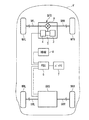
以下、図面を参照しながら、本発明の好ましい実施形態を詳細に説明する。図1に示すハイブリッド車両(以下、単に「車両」という)Vは、4つの車輪W(左右の前輪WFL、WFR及び左右の後輪WRL、WRR)を有する四輪車両である。車両Vには、前輪WFL、WFRを駆動するための前輪駆動装置DFSと、後輪WRL、WRRを駆動するための後輪駆動装置DRSが搭載されている。 Hereinafter, preferred embodiments of the present invention will be described in detail with reference to the drawings. A hybrid vehicle (hereinafter simply referred to as “vehicle”) V shown in FIG. 1 is a four-wheel vehicle having four wheels W (left and right front wheels WFL, WFR and left and right rear wheels WRL, WRR). The vehicle V is equipped with a front wheel drive device DFS for driving the front wheels WFL and WFR and a rear wheel drive device DRS for driving the rear wheels WRL and WRR.
前輪駆動装置DFSは、例えば、本出願人による特許第5362792号に開示されたものと同じであるので、以下、その構成及び動作について簡単に説明する。前輪駆動装置DFSは、動力源としての内燃機関(以下「エンジン」という)3と、発電可能な電動機で構成されたフロントモータ4と、エンジン3及びフロントモータ4の動力を変速し、前輪WFL、WFRに伝達する変速装置5を有している。
The front wheel drive device DFS is, for example, the same as that disclosed in Japanese Patent No. 5362922 by the applicant of the present invention, and therefore its configuration and operation will be briefly described below. The front wheel drive device DFS is an internal combustion engine (hereinafter referred to as “engine”) 3 as a power source, a
エンジン3は、例えばガソリンエンジンであり、その吸入空気量、燃料噴射量及び点火時期などを後述するECU2(図3参照)で制御することによって、エンジン3の動力が制御される。 The engine 3 is, for example, a gasoline engine, and the power of the engine 3 is controlled by controlling the intake air amount, the fuel injection amount, the ignition timing, and the like by an ECU 2 (see FIG. 3) described later.
フロントモータ4は、例えばブラシレスDCモータで構成され、ステータ及びロータ(いずれも図示せず)を有している。ステータは、パワードライブユニット(以下「PDU」という)6を介して、充放電可能なバッテリ7に電気的に接続されている。PDU6は、インバータなどの電気回路で構成されており、PDU6をECU2で制御することによって、フロントモータ4の動作が制御される。
The
具体的には、ECU2によるPDU6の制御により、バッテリ7からフロントモータ4のステータに電力が供給されると、その電力が動力に変換され、ロータが回転する(力行)。また、ステータへの電力供給が停止され、動力の入力によりロータが回転した状態で、その動力が電力に変換され、発電が行われる(回生)。発電した電力は、バッテリ7に充電されるか、又は後輪駆動装置DRSの後述する第1及び第2リヤモータ41、61に供給され、後輪WRL、WRRを駆動するのに用いられる。
Specifically, when electric power is supplied from the
また、車両Vには、エアコンのコンプレッサなどから成る補機8と、12Vバッテリ(図示せず)が搭載されており、補機8はPDU6を介して、12VバッテリはDC/DCコンバータ(図示せず)を介して、バッテリ7に電気的に接続されている。
Further, the vehicle V is equipped with an
変速装置5は、いわゆるデュアル・クラッチ・トランスミッション(DCT)で構成されている。図示しないが、変速装置5は、第1クラッチを介してエンジン3に接続された第1入力軸と、フロントモータ4と第1入力軸の間に配置された遊星歯車装置と、第2クラッチを介してエンジン3に接続された第2入力軸と、第1及び第2入力軸と平行な出力軸と、第1及び第2入力軸に回転自在に設けられた複数の入力ギヤと、出力軸に一体に設けられ、複数の入力ギヤに噛み合う複数の出力ギヤと、複数の入力ギヤの1つを第1又は第2入力軸に選択的に連結し、その入力ギヤとそれに噛み合う出力ギヤによるギヤ段を設定するシンクロ装置などを有している。
The
以上の構成により、第1及び第2クラッチ及びシンクロ装置などをECU2で制御することによって、第1及び第2クラッチの接続/遮断状態に応じて、エンジン3の動力及び/又はフロントモータ4の動力が第1入力軸に、又はエンジン3の動力が第2入力軸に、選択的に入力される。入力された動力は、シンクロ装置によって設定されたギヤ段による所定の変速比で変速された状態で、出力軸に出力され、さらに、ディファレンシャル9及び左右の前駆動軸SFL、SFRを介して、左右の前輪WFL、WFRに伝達される。
With the above configuration, the
図2に示すように、後輪駆動装置DRSは、第1リヤモータ41、第1遊星歯車装置51、第2リヤモータ61及び第2遊星歯車装置71を有している。これらの構成要素は、左右の後輪WRL、WRRの間に、41、51、71及び61の順に並んで配置され、左右の後駆動軸SRL、SRRと同軸状に設けられている。後駆動軸SRL、SRRの一端部は、それぞれ左右の後輪WRL、WRRに連結されている。
As shown in FIG. 2, the rear wheel drive device DRS includes a first
第1リヤモータ41は、フロントモータ4と同様、発電可能な電動機で構成されたブラシレスDCモータであり、ステータ42と、回転自在のロータ43を有している。ステータ42は、ケーシングCAに固定されており、PDU6を介して、フロントモータ4のステータ及びバッテリ7に電気的に接続されている。ロータ43は、中空の回転軸44に一体に設けられ、この回転軸44は、左後駆動軸SRLの外側に相対的に回転自在に設けられている。
Similar to the
第1リヤモータ41では、ECU2によるPDU6の制御により、バッテリ7の電力や、フロントモータ4で発電した電力が、ステータ42に供給されると、その電力が動力に変換され、ロータ43が回転する(力行)。この場合、ロータ43の動力は、ステータ42に供給される電力に応じて制御される。また、ステータ42への電力供給が停止され、動力の入力によりロータ43が回転した状態で、その動力が電力に変換され、発電が行われる(回生)とともに、発電した電力がバッテリ7に充電される。
In the first
第1遊星歯車装置51は、第1リヤモータ41の動力を減速し、左後輪WRLに伝達するためのものであり、第1サンギヤ52、第1リングギヤ53、2連ピニオンギヤ54及び第1キャリヤ55を有している。第1サンギヤ52は、上述した回転軸44に一体に設けられており、第1リヤモータ41のロータ43と一体に回転する。第1リングギヤ53は、中空の回転軸81に一体に設けられている。2連ピニオンギヤ54は、第1ピニオンギヤ54a及び第2ピニオンギヤ54bを一体に有しており、その数が3つ(2つのみ図示)である。また、2連ピニオンギヤ54は、第1キャリヤ55に回転自在に支持されており、その第1ピニオンギヤ54aが第1サンギヤ52に、第2ピニオンギヤ54bが第1リングギヤ53に、それぞれ噛み合っている。第1キャリヤ55は、左後駆動軸SRLの他端部に一体に設けられており、それと一体に回転する。
The first
第2リヤモータ61及び第2遊星歯車装置71は、上述した第1リヤモータ41及び第1遊星歯車装置51と同様に構成されているので、以下、その構成について簡単に説明する。第2リヤモータ61及び第2遊星歯車装置71は、後述するワンウェイクラッチ83を中心として、第1リヤモータ41及び第1遊星歯車装置51と対称に配置されている。第2リヤモータ61のステータ62は、ケーシングCAに固定されるとともに、PDU6を介して、フロントモータ4のステータ、バッテリ7及び第1リヤモータ41のステータ42に電気的に接続されている。また、第2リヤモータ61のロータ63は、中空の回転軸64に一体に設けられ、この回転軸64は、右後駆動軸SRRの外側に相対的に回転自在に設けられている。
Since the second
第2リヤモータ61では、ECU2によるPDU6の制御により、バッテリ7の電力や、フロントモータ4で発電した電力が、ステータ62に供給されると、その電力が動力に変換され、ロータ63が回転する(力行)。この場合、ロータ63の動力は、ステータ62に供給される電力に応じて制御される。また、ステータ62への電力供給が停止され、動力の入力によりロータ63が回転した状態で、その動力が電力に変換され、発電が行われる(回生)とともに、発電した電力がバッテリ7に充電される。
In the second
第2遊星歯車装置71は、第2リヤモータ61の動力を減速し、右後輪WRRに伝達するためのものであり、第2サンギヤ72、第2リングギヤ73、2連ピニオンギヤ74及び第2キャリヤ75を有している。第2サンギヤ72、第2リングギヤ73及び2連ピニオンギヤ74の歯数は、第1サンギヤ52、第1リングギヤ53及び2連ピニオンギヤ54の歯数とそれぞれ同じに設定されている。
The second
第2サンギヤ72は、上述した回転軸64に一体に設けられており、第2リヤモータ61のロータ63と一体に回転する。第2リングギヤ73は、中空の回転軸82に一体に設けられている。回転軸82は、前述した回転軸81と若干の隙間を存した状態で軸線方向に対向している。2連ピニオンギヤ74は、第2キャリヤ75に回転自在に支持されており、その第1ピニオンギヤ74aが第2サンギヤ72に、第2ピニオンギヤ74bが第2リングギヤ73に、それぞれ噛み合っている。第2キャリヤ75は、右後駆動軸SRRの他端部に一体に設けられており、それと一体に回転する。
The
後輪駆動装置DRSはさらに、ワンウェイクラッチ83及び油圧ブレーキ84を有している。ワンウェイクラッチ83は、インナーレース83a及びアウターレース83bを有しており、第1及び第2遊星歯車装置51、71の間に配置されている。なお、図2のスケルトン図では、図示の関係上、インナーレース83aとアウターレース83bは、実際の配置とは内外逆に描かれている。インナーレース83aは、前述した回転軸81、82にスプライン結合されており、それにより、インナーレース83a、回転軸81、82、第1及び第2リングギヤ53、73は、一体に回転する。また、アウターレース83bは、ケースCAに固定されている。
The rear wheel drive device DRS further includes a one-way clutch 83 and a
以上の構成により、ワンウェイクラッチ83は、回転軸81、82にそれらを逆転させる方向の動力が伝達されたときには、回転軸81、82をケースCAに接続することによって、回転軸81、82、第1及び第2リングギヤ53、73の逆転を阻止する一方、回転軸81、82にそれらを正転させる方向の動力が伝達されたときには、回転軸81、82とケースCAの間を遮断することによって、回転軸81、82、第1及び第2リングギヤ53、73の正転を許容する。
With the above configuration, the one-way clutch 83 connects the
油圧ブレーキ84は、多板式のクラッチで構成され、ケースCA及び回転軸81、82に取り付けられており、第1及び第2遊星歯車装置51、71の径方向外側に配置されている。油圧ブレーキ84は、ECU2で制御されることにより、第1及び第2リングギヤ53、73を制動する制動動作と、第1及び第2リングギヤ53、73の回転を許容する回転許容動作とを、選択的に実行する。油圧ブレーキ84の制動力は、ECU2によって制御される。
The
左右の前駆動軸SFL、SFR及び後駆動軸SRL、SRRにはそれぞれ、車輪回転数センサ101a〜101dが設けられている(図2参照)。車輪回転数センサ101a〜101dは、左右の前輪WFL、WFR及び後輪WRL、WRRの各回転数である車輪回転数NWFL、NWFR、NWRL及びNWRRを検出し、それらの検出信号をECU2に出力する(図3参照)。ECU2は、これらの検出信号と車輪Wの径に基づいて、車両Vの速度(車速)VPを算出する。
The left and right front drive shafts SFL, SFR and rear drive shafts SRL, SRR are respectively provided with wheel rotational speed sensors 101a-101d (see FIG. 2). Wheel rotation speed sensors 101a to 101d detect wheel rotation speeds NWFL, NWFR, NWRL and NWRR which are the rotation speeds of left and right front wheels WFL and WFR and rear wheels WRL and WRR, and output detection signals to
また、第1及び第2リヤモータ41、61のロータ43、63にはそれぞれ、モータ回転数センサ102a、102bが設けられている(図2参照)。モータ回転数センサ102a、102bはそれぞれ、ロータ43、63の各回転数であるモータ回転数NMOTL、NMOTRを検出し、それらの検出信号をECU2に出力する(図3参照)。さらに、ECU2には、アクセル開度センサ103から、車両Vのアクセルペダル(図示せず)の踏み込み量であるアクセル開度APを表す検出信号が入力される。
Further, motor
ECU2は、I/Oインターフェース、CPU、RAM及びROMなどから成るマイクロコンピュータで構成されている。ECU2は、上述したセンサ101〜103からの検出信号などに応じ、ROMに記憶された制御プログラムに従って、車両Vに要求される要求制駆動力を算出し、この要求制駆動力などに基づき、前輪駆動装置DFS及び後輪駆動装置DRSの動作モードを決定する。また、エンジン3、フロントモータ4、第1及び第2リヤモータ41、61の各々に要求される要求トルクを算出するとともに、各目標トルクを設定する。そして、設定された目標トルクに基づき、これらの構成要素などの動作を制御することによって、各車輪Wを制駆動し、車両Vの動作を制御する。なお、本実施形態では、ECU2が、換算値算出手段、制駆動力取得手段、ねじれ分相当値算出手段、電動機制御手段、要求制駆動力算出手段、補正手段、及び補正禁止手段に相当する。
The
上記の前輪駆動装置DFSの動作モードには、エンジン3のみを車両Vの動力源として用いるENG走行モードと、フロントモータ4のみを動力源として用いるEV走行モードと、エンジン3をフロントモータ4でアシストするアシスト走行モードと、エンジン3の動力の一部を用いてフロントモータ4でバッテリ7を充電する充電走行モードと、車両Vの減速走行中の走行エネルギを用いてフロントモータ4でバッテリ7を充電する減速回生モードなどが含まれる。
The operation mode of the front wheel drive device DFS described above includes an ENG travel mode in which only the engine 3 is used as a power source for the vehicle V, an EV travel mode in which only the
また、後輪駆動装置DRSの動作モードには、駆動モード、回生(制動)モード及び左右逆駆動モードなどが含まれる。以下、これらの動作モードについて順に説明する。 Further, the operation modes of the rear wheel drive device DRS include a drive mode, a regeneration (braking) mode, a left / right reverse drive mode, and the like. Hereinafter, these operation modes will be described in order.
[駆動モード]
この駆動モードは、車両Vの加速走行中などに、バッテリ7の電力を用いて第1及び第2リヤモータ41、61で力行を行い、それらの動力で左右の後輪WRL、WRRを駆動する動作モードである。この駆動モードでは、基本的に、第1及び第2リヤモータ41、61の目標トルクTROBJが互いに同じ正値に設定される。そして、目標トルクTROBJに応じた電力を第1及び第2リヤモータ41、61に供給し、ロータ43、63を正転させることによって、ワンウェイクラッチ83を係合させるとともに、油圧ブレーキ84で第1及び第2リングギヤ53、73を制動する。
[Drive mode]
This drive mode is an operation in which the first and second
前述した後輪駆動装置DRSにおける各種の回転要素の間の連結関係から明らかなように、第1サンギヤ52の回転数は、第1リヤモータ41(ロータ43)の回転数と等しく、第1キャリヤ55の回転数は、左後輪WRLの回転数と、第1リングギヤ53の回転数は、第2リングギヤ73の回転数と、それぞれ等しい。また、第2サンギヤ72の回転数は、第2リヤモータ61(ロータ63)の回転数と等しく、第2キャリヤ75の回転数は、右後輪WRRの回転数と等しい。また、周知のように、第1サンギヤ52の回転数、第1キャリヤ55の回転数及び第1リングギヤ53の回転数は、共線図において、1つの直線上に位置する共線関係にあり、第1サンギヤ52及び第1リングギヤ53は、第1キャリヤ55の両側に位置する。以上の関係は、第2サンギヤ72、第2キャリヤ75及び第2リングギヤ73についても、同様に当てはまる。
As is clear from the connection relationship between the various rotary elements in the rear wheel drive device DRS described above, the rotational speed of the
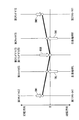
以上から、各種の回転要素の間の回転数の関係は、図4に示す共線図のように表される。なお、同図および後述する他の共線図では、値0を示す横軸から縦軸上の白丸までの距離が、各回転要素の回転数に相当する。また、図4において、TM1は、力行に伴って発生する第1リヤモータ41の出力トルク(以下「第1リヤモータ力行トルク」という)であり、TM2は、力行に伴って発生する第2リヤモータ61の出力トルク(以下「第2リヤモータ力行トルク」という)である。また、RRLは、左後輪の反力トルクであり、RRRは、右後輪WRRの反力トルク、ROWは、ワンウェイクラッチ83の反力トルクである。
From the above, the relationship between the rotational speeds of the various rotating elements is expressed as shown in the alignment chart shown in FIG. In this figure and other collinear charts described later, the distance from the horizontal axis indicating the
前述したように、ワンウェイクラッチ83は、第1及び第2リングギヤ53、73の逆転を阻止するように構成されている。また、図4から明らかなように、第1リヤモータ力行トルクTM1は、第1サンギヤ52を正転させるとともに、第1リングギヤ53を逆転させるように作用する。以上により、第1リヤモータ力行トルクTM1は、第1リングギヤ53に作用するワンウェイクラッチ83の反力トルクROWを反力とし、第1キャリヤ55及び左後駆動軸SRLを介して、左後輪WRLに伝達され、その結果、左後輪WRLが駆動される。同様に、第2リヤモータ力行トルクTM2は、第2リングギヤ73に作用するワンウェイクラッチ83の反力トルクROWを反力とし、第2キャリヤ75及び右後駆動軸SRRを介して、右後輪WRRに伝達され、その結果、右後輪WRRが正転する。
As described above, the one-way clutch 83 is configured to prevent reverse rotation of the first and second ring gears 53 and 73. As is clear from FIG. 4, the first rear motor power running torque TM1 acts to cause the
[回生モード]
この回生モードは、車両Vの減速走行中などに、車両Vの走行エネルギを用いて、第1及び第2リヤモータ41、61で、後輪WRL、WRRを制動しながら回生を行い、発電した電力をバッテリ7に充電する動作モードである。この回生モードでは、基本的に、第1及び第2リヤモータ41、61の目標トルクTROBJが互いに同じ負値に設定され、その値に応じて、第1及び第2リヤモータ41、61で回生される電力を制御するとともに、油圧ブレーキ84で第1及び第2リングギヤ53、73を制動する。
[Regeneration mode]
In this regenerative mode, electric power generated by performing regeneration while braking the rear wheels WRL and WRR by the first and second
図5は、回生モードにおける各種の回転要素の間の回転数の関係及びトルクの釣合関係を示している。同図において、BM1は、回生に伴って発生する第1リヤモータ41の出力(制動)トルク(以下「第1リヤモータ回生トルク」という)であり、BM2は、回生に伴って発生する第2リヤモータ61の出力(制動)トルク(以下「第2リヤモータ回生トルク」という)である。また、TRLは、左駆動輪WRLの慣性トルクであり、TRRは、右駆動輪WRRの慣性トルク、RBRは、油圧ブレーキ84の反力トルクである。
FIG. 5 shows the rotational speed relationship and the torque balance relationship between the various rotary elements in the regeneration mode. In the figure, BM1 is an output (braking) torque of the first rear motor 41 (hereinafter referred to as “first rear motor regeneration torque”) generated along with regeneration, and BM2 is a second
図5から明らかなように、第1及び第2サンギヤ52、53にそれぞれ伝達された第1及び第2リヤモータ回生トルクBM1、BM2は、油圧ブレーキ84の反力トルクRBRを反力として、第1及び第2キャリヤ55、75にそれぞれ伝達され、さらに、左右の後駆動軸SRL、SRRを介して、左右の後輪WRL、WRRに伝達される。その結果、左右の後輪WRL、WRRが制動される。
As is apparent from FIG. 5, the first and second rear motor regenerative torques BM1 and BM2 transmitted to the first and second sun gears 52 and 53, respectively, are obtained using the reaction force torque RBR of the
[左右逆駆動モード]
この左右逆駆動モードは、車両Vの旋回時などに、第1及び第2リヤモータ41、61の一方で力行を行うと同時に、他方で回生を行う動作モードである。この左右逆駆動モードでは、第1及び第2目標トルクTRLOBJ、TRROBJの一方が正値に、他方が負値に設定され、それらの値に応じて、一方に供給される電力及び他方で回生される電力を制御するとともに、油圧ブレーキ84で第1及び第2リングギヤ53、73を制動する。図6は、第1リヤモータ41で力行を、第2リヤモータ61で回生を行ったときの、各種の回転要素の間の回転数の関係及びトルクの釣合関係を示している。同図における各種のパラメータは、図4及び図5を参照して説明したとおりである。
[Reverse drive mode]
The left / right reverse drive mode is an operation mode in which, when the vehicle V is turning, for example, the first and second
図6と、これまでの説明から明らかなように、第1リヤモータ力行トルクTM1が、第1遊星歯車装置51を介して左後輪WRLに伝達されることにより、左後輪WRLが駆動されるとともに、第2リヤモータ回生トルクBM2が、第2遊星歯車装置71を介して右後輪WRRに伝達されることにより、右後輪WRRが制動される。図示しないが、上記とは逆に、第1リヤモータ41で回生を、第2リヤモータ61で力行を行った場合には、トルクなどの関係が図6の場合と逆になる。
As is clear from FIG. 6 and the above description, the first rear motor power running torque TM1 is transmitted to the left rear wheel WRL via the first
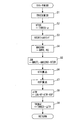
次に、ECU2で実行されるリヤモータ制御について説明する。このリヤモータ制御は、第1及び第2リヤモータ41、61に対してそれぞれ同様に実行される。以下、これらを代表し、図7を参照しながら、第1リヤモータ41の場合の制御処理を説明する。本処理は、所定の制御周期で繰り返し実行される。
Next, rear motor control executed by the
本処理では、まずステップ1(「S1」と図示。以下同じ)において、第1リヤモータ41に要求されるモータ要求トルクTRREQを算出する。次に、算出されたモータ要求トルクTRREQに換算係数αを乗算することによって、ねじれ分回転数NTORを算出する(ステップ2)。このねじれ分回転数NTORは、モータ回転数センサ102a及び車輪回転数センサ101cの設置位置間における、第1リヤモータ41のトルクによる左後駆動軸SRLのねじれを主とする動力伝達系のねじれ分に相当する回転数を表す。また、換算係数αは、モータ要求トルクTRREQをねじれ分回転数NTORに換算するための所定の係数であり、実験などによりあらかじめ設定される。
In this process, first, in step 1 (illustrated as “S1”, the same applies hereinafter), a motor request torque TRREQ required for the first
次に、算出されたねじれ分回転数NTORに対して、フィルタリング処理を施す(ステップ3)。このフィルタリング処理は、第1リヤモータ41からトルクが出力された後、そのトルクに応じたねじれが動力伝達系に発生するまでの遅れを補償するためのものであり、例えば、次式(1)による加重平均によって行われる。
NTOR=NTOR・KF+NTORZ・(1−KF) ・・・(1)
ここで、NTORZは、ねじれ分回転数NTORの前回値、KFは所定の重み係数である(0<KF<1)。
Next, a filtering process is performed on the calculated twisted rotation speed NTOR (step 3). This filtering process is for compensating for a delay until the torsion corresponding to the torque is generated in the power transmission system after the torque is output from the first
NTOR = NTOR.KF + NTORZ. (1-KF) (1)
Here, NTORZ is the previous value of the rotational speed NTOR for the twist, and KF is a predetermined weighting factor (0 <KF <1).
次に、検出された左後輪WRLの車輪回転数NWRLにギヤ比RGを乗算することによって、後輪回転数換算値NWCONVを算出する(ステップ4)。このギヤ比RGは、第1リヤモータ41から左後駆動軸SRLまでの変速比、すなわち第1遊星歯車装置51の第1サンギヤ52、2連ピニオンギヤ54及び第1リングギヤ53のギヤ比に相当する。以上から明らかなように、後輪回転数換算値NWCONVは、第1リヤモータ41の回転数であるモータ回転数NMOTLを基準値とするとともに、車輪回転数NWRLを、ギヤ比RGに基づき、モータ回転数NMOTLを基準として、第1リヤモータ41の位置における回転数に換算したものである。
Next, a rear wheel rotational speed converted value NWCONV is calculated by multiplying the detected wheel rotational speed NWRL of the left rear wheel WRL by the gear ratio RG (step 4). The gear ratio RG corresponds to the gear ratio from the first
次に、モータ回転数センサ102aで検出されたモータ回転数NMOTLと、上記ステップ3及び4で算出されたねじれ分回転数NTOR及び後輪回転数換算値NWCONVを用い、次式(2)によって、回転数偏差ΔNを算出する(ステップ5)。
ΔN=(NMOTL−NWCONV)−NTOR ・・・(2)
式(2)から明らかなように、回転数偏差ΔNは、基本的に、ねじれ分回転数NTORと後輪回転数換算値NWCONVLとの差であり、さらにねじれ分回転数NTORを差し引くことによって、動力伝達系のねじれ分の回転数を補償したものである。
Next, using the motor rotational speed NMOTL detected by the motor
ΔN = (NMOTL−NWCONV) −NTOR (2)
As apparent from the equation (2), the rotational speed deviation ΔN is basically the difference between the twisting rotational speed NTOR and the rear wheel rotational speed converted value NWCONVL, and by subtracting the twisting rotational speed NTOR, This compensates for the rotational speed of the twist of the power transmission system.
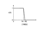
次に、ステップ1で算出したモータ要求トルクTRREQに応じ、図8のマップを参照することによって、トルク補正係数KTRを算出する(ステップ6)。このマップでは、トルク補正係数KTRは、モータ要求トルクの絶対値|TRREQ|が、値0に近い第1所定値TR1以下のときには値1に設定され、第1所定値TR1と第2所定値TR2の間ではリニアに減少し、第2所定値TR2よりも大きいときには値0に設定されている。
Next, the torque correction coefficient KTR is calculated by referring to the map of FIG. 8 according to the motor required torque TRREQ calculated in step 1 (step 6). In this map, the torque correction coefficient KTR is set to a
次に、車速VPに応じ、図9のマップを参照することによって、車速補正係数KVPを算出する(ステップ7)。このマップでは、車速補正係数KTRは、車速VPが所定の第3速度V3以上でかつ第1速度V1以下のときに、値1に設定されている。また、車速補正係数KVPは、車速VPが第1速度V1よりも大きな所定の第4速度V4以上のときに、所定値K1(0<K1<1)に設定され、第1速度V1と第4速度V4の間では、車速VPが増加するにつれて値1から所定値K1まで減少するように設定されている。また、車速VPが第3速度V3よりも小さな、値0付近の所定の第2速度V2以下のときには、車速補正係数KVPは値0に設定されている。
Next, the vehicle speed correction coefficient KVP is calculated by referring to the map of FIG. 9 according to the vehicle speed VP (step 7). In this map, the vehicle speed correction coefficient KTR is set to a
次に、次式(3)により、ステップ5で算出された回転数偏差ΔNに、所定のフィードバックゲイン(P項ゲイン)KP、トルク補正係数KTR及び車速補正係数KVPを乗算することによって、フィードバック補正項ΔTRを算出する(ステップ8)。
ΔTR=ΔN・KP・KTR・KVP ・・・(3)
Next, feedback correction is performed by multiplying the rotational speed deviation ΔN calculated in
ΔTR = ΔN · KP · KTR · KVP (3)
次に、モータ要求トルクTRREQからフィードバック補正項ΔTRを減算することによって、第1リヤモータ41の目標トルクTROBJを算出し(ステップ9)、本処理を終了する。前述したように、ECU2は、以上のように設定された目標トルクTROBJが得られるように、第1リヤモータ41の動作を制御する。なお、前述したように、第2リヤモータ61についても、図7と同様のリヤモータ制御処理が実行され、目標トルクTROBJが設定される。
Next, the target torque TROBJ of the first
以上のように、本実施形態によれば、左後輪WRLの車輪回転数NWRLを、第1遊星歯車装置51のギヤ比RGを用いて、第1リヤモータ41の位置における回転数に換算した後輪回転数換算値NWCONVを算出する(図7のステップ4)。また、第1リヤモータ41のモータ要求トルクTRREQに基づき、モータ回転数センサ102aL及び車輪回転数センサ101cの設置位置間における動力伝達系のねじれ分に相当するねじれ分回転数NTORを算出する(ステップ2)。さらに、第1リヤモータ41のモータ回転数NMOTLと後輪回転数換算値NWCONVの差(NMOTL−NWCONV)から、ねじれ分回転数NTORをさらに減算した値を、回転数偏差ΔNとして算出する(ステップ5)。
As described above, according to the present embodiment, after the wheel rotational speed NWRL of the left rear wheel WRL is converted into the rotational speed at the position of the first
そして、この回転数偏差ΔNにフィードバックゲインKP及び補正係数KTR、KVPを乗算することによって、フィードバック補正項ΔTRを算出する(ステップ8)とともに、モータ要求トルクTRREQからフィードバック補正項ΔTRを減算した値を、第1リヤモータ41の目標トルクTROBJとして設定する(ステップ9)。このような目標トルクTROBJの設定は、第2リヤモータ61についても同様に行われる。
A feedback correction term ΔTR is calculated by multiplying the rotational speed deviation ΔN by the feedback gain KP and the correction coefficients KTR and KVP (step 8), and a value obtained by subtracting the feedback correction term ΔTR from the motor request torque TRREQ is calculated. The target torque TROBJ of the first
以上の制御により、第1又は第2リヤモータ41、61の駆動/制動状態の切替時にバックラッシュ詰まりが発生し、その途中で第1又は第2リヤモータ41、61の回転数が急激に変動したときには、第1又は第2リヤモータ41、61の目標トルクTROBJが、フィードバック補正項ΔTRによるモータ要求トルクTRREQの補正によって、回転数偏差ΔNが減少する方向に設定される。これにより、第1又は第2リヤモータ41、61の回転数の変動を確実に抑制でき、バックラッシュ詰まりの終了時におけるショックや異音、振動などの不具合を適切に抑制することができる。
With the above control, when backlash clogging occurs during switching of the driving / braking state of the first or second
また、回転数偏差ΔNを算出する際に、動力伝達系のねじれ分に相当するねじれ分回転数NTORを減算するので、動力伝達系のねじれによる回転数のずれを補償しながら、フィードバック補正項ΔTRの算出、及び第1及び第2リヤモータ41、61の目標トルクTROBJの設定をより適切に行うことができ、上述した効果をより良好に得ることができる。
Further, when calculating the rotational speed deviation ΔN, the rotational speed NTOR corresponding to the twist of the power transmission system is subtracted, so that the feedback correction term ΔTR is compensated while compensating for the rotational speed deviation caused by the twist of the power transmission system. And the setting of the target torque TROBJ of the first and second
また、モータ要求トルクTRREQの絶対値が第2所定値TR2を上回ったときには、トルク補正係数KTRが値0に設定されることによって、車速VPが値0付近の第2車速V2以下のときには、車速補正係数KVPが値0に設定されることによって、それぞれモータ要求トルクTRREQの補正が実質的に禁止される。これにより、第1又は第2リヤモータ41、61の駆動/制動状態が切り替わる可能性が高い場合においてのみ、モータ要求トルクTRREQの補正を効果的に行うことができる。
Further, when the absolute value of the motor required torque TRREQ exceeds the second predetermined value TR2, the torque correction coefficient KTR is set to the
さらに、車速VPが第1速度V1以上で第4速度V4以下のときには、車速VPが高いほど、車速補正係数KVPがより小さな値に設定されることで、モータ要求トルクTRREQの補正度合がより低減されるので、モータ要求トルクTRREQの補正をその必要性に応じて適切に行うことができる。 Further, when the vehicle speed VP is equal to or higher than the first speed V1 and equal to or lower than the fourth speed V4, the vehicle speed correction coefficient KVP is set to a smaller value as the vehicle speed VP is higher, so that the correction degree of the motor required torque TRREQ is further reduced. Therefore, the correction of the motor required torque TRREQ can be appropriately performed according to the necessity.
なお、本発明は、説明した実施形態に限定されることなく、種々の態様で実施することができる。例えば、実施形態では、リヤモータ側と車輪側との回転数偏差ΔNを算出する際に、ギヤ比RGを用い、車輪回転数NWRL、NWRRを、モータ回転数NMOTL、NMOTRに相当する値に換算しているが、これとは逆に、モータ回転数NMOTL、NMOTRを、車輪回転数NWRL、NWRRに相当する値に換算してもよい。 In addition, this invention can be implemented in various aspects, without being limited to the described embodiment. For example, in the embodiment, when calculating the rotational speed deviation ΔN between the rear motor side and the wheel side, the gear ratio RG is used to convert the wheel rotational speeds NWRL and NWRR into values corresponding to the motor rotational speeds NMOTL and NMOTR. However, conversely, the motor rotation speeds NMOTL and NMOTR may be converted into values corresponding to the wheel rotation speeds NWRL and NWRR.
また、実施形態では、ねじれ分回転数NTORの算出を、モータ要求トルクTRREQに所定の換算係数αを乗算することによって行っているが、これに限らず、他の適当な算出方法を採用することが可能である。さらに、実施形態では、車速VPをすべての車輪Wの車輪回転数NWFL、NWFR、NWRL及びNWRRに基づいて算出しているが、左右の前輪側の車輪回転数NWFL、NWFRのみ、又は左右の後輪側の車輪回転数NWRL、NWRRのみに基づいて、車速VPを算出してもよい。 In the embodiment, the calculation of the torsional rotational speed NTOR is performed by multiplying the motor required torque TRREQ by a predetermined conversion coefficient α. However, the present invention is not limited to this, and other appropriate calculation methods are adopted. Is possible. Furthermore, in the embodiment, the vehicle speed VP is calculated based on the wheel rotation speeds NWFL, NWFR, NWRL, and NWRR of all the wheels W. However, the wheel rotation speeds NWFL and NWFR on the left and right front wheels only, or the left and right rear wheels The vehicle speed VP may be calculated based only on the wheel speeds NWRL and NWRR on the wheel side.
また、実施形態では、左右の後輪WRL、WRRを左右のリヤモータ41、61でそれぞれ制駆動するとともに、リヤモータ41、61のそれぞれについて、モータ回転数NMOTL、NMOTRとそれに対応する左右の車輪回転数NWRL、NWRRとの関係から、目標トルクTROBJを互いに独立して設定している。本発明は、これに限らず、車輪が発電可能な電動機で制駆動される限り、適用でき、例えば、後輪WRL、WRRを単一のリヤモータで制駆動する場合にも適用可能である。
In the embodiment, the left and right rear wheels WRL and WRR are driven and controlled by the left and right
あるいは、実施形態とは前後逆の関係で、エンジン及びモータを後輪側に配置し、発電可能なモータを前輪側に配置した場合にも、本発明を適用できる。また、発電可能なモータを配置した以外の車輪を駆動する他の車両駆動装置の構成は任意であり、その駆動源がエンジンのみ又はモータのみで構成される車両でもよく、あるいは、他の車両駆動装置をもたない車両でもよい。前輪及び後輪がそれぞれのモータで制駆動される場合には、前輪及び後輪をそれぞれ対象として、本発明を適用することが可能である。その他、本発明の趣旨の範囲内で、細部の構成を適宜、変更することが可能である。 Alternatively, the present invention can also be applied to the case where the engine and the motor are arranged on the rear wheel side and the motor capable of generating power is arranged on the front wheel side in a reverse relationship with the embodiment. Moreover, the structure of the other vehicle drive device which drives the wheel other than arranging the motor capable of generating electricity is arbitrary, and the drive source may be a vehicle composed of only the engine or only the motor, or another vehicle drive A vehicle without an apparatus may be used. In the case where the front wheels and the rear wheels are driven by the respective motors, the present invention can be applied to the front wheels and the rear wheels, respectively. In addition, it is possible to appropriately change the detailed configuration within the scope of the gist of the present invention.
2 ECU(換算値算出手段、制駆動力取得手段、ねじれ分相当値算出手段、 電動機制御手段、要求制駆動力算出手段、補正手段、補正禁止手段)
41 第1リヤモータ(電動機)
52 第1サンギヤ(ギヤ)
53 第1リングギヤ(ギヤ)
54 2連ピニオンギヤ(ギヤ)
61 第2リヤモータ(電動機)
72 第2サンギヤ(ギヤ)
73 第2リングギヤ(ギヤ)
74 2連ピニオンギヤ(ギヤ)
101a 車輪回転数センサ(車速取得手段)
101b 車輪回転数センサ(車速取得手段)
101c 車輪回転数センサ(車速取得手段、第2回転速度パラメータ取得手段)
101d 車輪回転数センサ(車速取得手段、第2回転速度パラメータ取得手段)
102a モータ回転数センサ(第1回転速度パラメータ取得手段)
102b モータ回転数センサ(第1回転速度パラメータ取得手段)
V ハイブリッド車両(車両)
WRL 左後輪(車輪)
WRR 右後輪(車輪)
NMOTL モータ回転数(第1回転速度パラメータ、基準値)
NMOTR モータ回転数(第1回転速度パラメータ、基準値)
NWRL 左後輪の車輪回転数(第2回転速度パラメータ)
NWRR 右後輪の車輪回転数(第2回転速度パラメータ)
RG ギヤ比
NWCONV 後輪回転数換算値(換算値)
NTOR ねじれ分回転数(ねじれ分相当値)
TRREQ モータ要求トルク(電動機の制駆動力、電動機の要求制駆動力)
TROBJ リヤモータの目標トルク
TR2 第2所定値(所定値)
VP 車速(車両の速度)
V1 第1速度
V2 第2速度
2 ECU (conversion value calculation means, braking / driving force acquisition means, twist equivalent value calculation means, motor control means, required braking / driving force calculation means, correction means, correction prohibition means)
41 First rear motor (electric motor)
52 1st sun gear (gear)
53 First ring gear (gear)
54 Double pinion gear (gear)
61 Second rear motor (electric motor)
72 Second sun gear (gear)
73 Second ring gear (gear)
74 Double pinion gear (gear)
101a Wheel speed sensor (vehicle speed acquisition means)
101b Wheel rotation speed sensor (vehicle speed acquisition means)
101c Wheel rotation speed sensor (vehicle speed acquisition means, second rotation speed parameter acquisition means)
101d Wheel rotational speed sensor (vehicle speed acquisition means, second rotational speed parameter acquisition means)
102a Motor rotational speed sensor (first rotational speed parameter acquisition means)
102b Motor rotation speed sensor (first rotation speed parameter acquisition means)
V Hybrid vehicle (vehicle)
WRL Left rear wheel (wheel)
WRR Right rear wheel (wheel)
NMOTL Motor rotation speed (first rotation speed parameter, reference value)
NMOTR Motor rotation speed (first rotation speed parameter, reference value)
NWRL Wheel speed of the left rear wheel (second rotational speed parameter)
NWRR Wheel speed of the right rear wheel (second rotational speed parameter)
RG Gear ratio NWCONV Rear wheel speed conversion value (converted value)
NTOR Twist rotation speed (twist equivalent value)
TRREQ Required motor torque (braking / driving force of motor, required braking / driving force of motor)
TROBJ Target torque of rear motor TR2 Second predetermined value (predetermined value)
VP vehicle speed (vehicle speed)
V1 1st speed V2 2nd speed
Claims (3)
前記動力伝達系よりも前記電動機側である所定の第1位置における回転速度を表す第1回転速度パラメータを取得する第1回転速度パラメータ取得手段と、
前記動力伝達系よりも前記車輪側である所定の第2位置における回転速度を表す第2回転速度パラメータを取得する第2回転速度パラメータ取得手段と、
前記取得された第1及び第2回転速度パラメータの一方を基準値とするとともに、前記複数のギヤのギヤ比に基づき、前記第1及び第2回転速度パラメータの他方を前記基準値を基準として換算した値を、換算値として算出する換算値算出手段と、
前記車輪を駆動又は制動する前記電動機の制駆動力を取得する制駆動力取得手段と、
該取得された電動機の制駆動力に基づき、前記第1位置と前記第2位置との間における前記動力伝達系のねじれ分に相当する回転速度パラメータを、ねじれ分相当値として算出するねじれ分相当値算出手段と、
前記基準値と前記算出された換算値との乖離度合、及び前記算出されたねじれ分相当値に基づいて、前記電動機を制御する電動機制御手段と、を備え、
前記電動機制御手段は、
前記車両の運転状態に基づいて、前記電動機に要求される要求制駆動力を算出する要求制駆動力算出手段と、
該算出された要求制駆動力を、前記乖離度合及び前記ねじれ分相当値に基づき、前記乖離度合が減少するように補正することによって、前記電動機の目標制駆動力を設定する補正手段と、を有し、
前記補正手段は、前記要求制駆動力の絶対値が所定値以下のときに、前記要求制駆動力の補正を実行することを特徴とする車両用電動機の制御装置。 Control device for vehicle motor that controls a motor capable of generating electricity that is mechanically coupled to a vehicle wheel via a power transmission system having a plurality of gears meshing with each other and that drives or brakes the wheel via the power transmission system Because
First rotation speed parameter acquisition means for acquiring a first rotation speed parameter representing a rotation speed at a predetermined first position on the electric motor side of the power transmission system;
Second rotational speed parameter acquisition means for acquiring a second rotational speed parameter representing a rotational speed at a predetermined second position on the wheel side of the power transmission system;
One of the acquired first and second rotational speed parameters is used as a reference value, and the other of the first and second rotational speed parameters is converted based on the reference value based on the gear ratio of the plurality of gears. Converted value calculating means for calculating the converted value as a converted value;
Braking / driving force acquisition means for acquiring braking / driving force of the electric motor for driving or braking the wheel;
Based on the obtained braking / driving force of the electric motor, the rotation speed parameter corresponding to the twist of the power transmission system between the first position and the second position is calculated as a twist equivalent value. A value calculating means;
Electric motor control means for controlling the electric motor based on the degree of divergence between the reference value and the calculated converted value, and the calculated equivalent to twist amount , and
The motor control means includes
A required braking / driving force calculating means for calculating a required braking / driving force required for the electric motor based on a driving state of the vehicle;
Correcting means for setting the target braking / driving force of the electric motor by correcting the calculated required braking / driving force based on the deviation degree and the twist equivalent value so that the deviation degree is reduced; Have
The correction means, when the absolute value of the demand force is below a predetermined value, a control device for a vehicle electric motor, it characterized that you perform the correction of the demand force.
前記動力伝達系よりも前記電動機側である所定の第1位置における回転速度を表す第1回転速度パラメータを取得する第1回転速度パラメータ取得手段と、
前記動力伝達系よりも前記車輪側である所定の第2位置における回転速度を表す第2回転速度パラメータを取得する第2回転速度パラメータ取得手段と、
前記取得された第1及び第2回転速度パラメータの一方を基準値とするとともに、前記複数のギヤのギヤ比に基づき、前記第1及び第2回転速度パラメータの他方を前記基準値を基準として換算した値を、換算値として算出する換算値算出手段と、
前記車輪を駆動又は制動する前記電動機の制駆動力を取得する制駆動力取得手段と、
該取得された電動機の制駆動力に基づき、前記第1位置と前記第2位置との間における前記動力伝達系のねじれ分に相当する回転速度パラメータを、ねじれ分相当値として算出するねじれ分相当値算出手段と、
前記基準値と前記算出された換算値との乖離度合、及び前記算出されたねじれ分相当値に基づいて、前記電動機を制御する電動機制御手段と、を備え、
前記電動機制御手段は、
前記車両の運転状態に基づいて、前記電動機に要求される要求制駆動力を算出する要求制駆動力算出手段と、
該算出された要求制駆動力を、前記乖離度合及び前記ねじれ分相当値に基づき、前記乖離度合が減少するように補正することによって、前記電動機の目標制駆動力を設定する補正手段と、を有し、
前記車両の速度を取得する車速取得手段をさらに備え、
前記補正手段は、前記取得された車両の速度が所定の第1速度以上のときには、該車両の速度が高いほど、前記要求制駆動力の補正度合をより低減することを特徴とする車両用電動機の制御装置。 Control device for vehicle motor that controls a motor capable of generating electricity that is mechanically coupled to a vehicle wheel via a power transmission system having a plurality of gears meshing with each other and that drives or brakes the wheel via the power transmission system Because
First rotation speed parameter acquisition means for acquiring a first rotation speed parameter representing a rotation speed at a predetermined first position on the electric motor side of the power transmission system;
Second rotational speed parameter acquisition means for acquiring a second rotational speed parameter representing a rotational speed at a predetermined second position on the wheel side of the power transmission system;
One of the acquired first and second rotational speed parameters is used as a reference value, and the other of the first and second rotational speed parameters is converted based on the reference value based on the gear ratio of the plurality of gears. Converted value calculating means for calculating the converted value as a converted value;
Braking / driving force acquisition means for acquiring braking / driving force of the electric motor for driving or braking the wheel;
Based on the obtained braking / driving force of the electric motor, the rotation speed parameter corresponding to the twist of the power transmission system between the first position and the second position is calculated as a twist equivalent value. A value calculating means;
Electric motor control means for controlling the electric motor based on the degree of divergence between the reference value and the calculated converted value, and the calculated equivalent to twist amount, and
The motor control means includes
A required braking / driving force calculating means for calculating a required braking / driving force required for the electric motor based on a driving state of the vehicle;
Correcting means for setting the target braking / driving force of the electric motor by correcting the calculated required braking / driving force based on the deviation degree and the twist equivalent value so that the deviation degree is reduced; Have
Vehicle speed acquisition means for acquiring the speed of the vehicle,
Wherein the correction means, when the speed of the acquired vehicle is equal to or larger than a predetermined first speed, as the speed of the vehicle is high, vehicle dual motor, characterized by further reducing the correction degree of the demand force Control device.
Priority Applications (1)
| Application Number | Priority Date | Filing Date | Title |
|---|---|---|---|
| JP2013265231A JP6200312B2 (en) | 2013-12-24 | 2013-12-24 | Control device for electric motor for vehicle |
Applications Claiming Priority (1)
| Application Number | Priority Date | Filing Date | Title |
|---|---|---|---|
| JP2013265231A JP6200312B2 (en) | 2013-12-24 | 2013-12-24 | Control device for electric motor for vehicle |
Publications (2)
| Publication Number | Publication Date |
|---|---|
| JP2015122871A JP2015122871A (en) | 2015-07-02 |
| JP6200312B2 true JP6200312B2 (en) | 2017-09-20 |
Family
ID=53534034
Family Applications (1)
| Application Number | Title | Priority Date | Filing Date |
|---|---|---|---|
| JP2013265231A Active JP6200312B2 (en) | 2013-12-24 | 2013-12-24 | Control device for electric motor for vehicle |
Country Status (1)
| Country | Link |
|---|---|
| JP (1) | JP6200312B2 (en) |
Families Citing this family (2)
| Publication number | Priority date | Publication date | Assignee | Title |
|---|---|---|---|---|
| US11091021B2 (en) | 2016-08-24 | 2021-08-17 | Honda Motor Co., Ltd. | Power plant |
| CN109552069A (en) * | 2018-12-24 | 2019-04-02 | 上海大郡动力控制技术有限公司 | Based on the pure electric automobile jitter suppression method for leaning on tooth strategy and active damping |
Family Cites Families (5)
| Publication number | Priority date | Publication date | Assignee | Title |
|---|---|---|---|---|
| JP2737065B2 (en) * | 1991-12-13 | 1998-04-08 | 東洋電機製造株式会社 | Torsional vibration suppression control method |
| US6806667B1 (en) * | 2003-05-23 | 2004-10-19 | Toyota Jidosha Kabushiki Kaisha | Control unit and control method for controlling vibration of an electric vehicle |
| JP2009196533A (en) * | 2008-02-22 | 2009-09-03 | Aisin Aw Co Ltd | Dynamo-electric machine control system and vehicle driving system having the dynamo-electric machine control system |
| JP4877296B2 (en) * | 2008-08-21 | 2012-02-15 | トヨタ自動車株式会社 | DRIVE DEVICE AND CONTROL DEVICE THEREOF |
| JP5226627B2 (en) * | 2009-07-31 | 2013-07-03 | 本田技研工業株式会社 | Vehicle drive control device |
-
2013
- 2013-12-24 JP JP2013265231A patent/JP6200312B2/en active Active
Also Published As
| Publication number | Publication date |
|---|---|
| JP2015122871A (en) | 2015-07-02 |
Similar Documents
| Publication | Publication Date | Title |
|---|---|---|
| JP6666449B2 (en) | Power unit | |
| JP4548543B2 (en) | Drive torque control device for hybrid vehicle | |
| JP2005138743A (en) | Driving force control device of hybrid vehicle | |
| US8512202B2 (en) | Shift controller and shift controlling method | |
| US20080302590A1 (en) | Drive system for vehicle | |
| JP2005016559A (en) | Mode transition controller of hybrid car | |
| JP6029572B2 (en) | Vehicle slip determination device | |
| JP5971330B2 (en) | Drive control apparatus for hybrid vehicle | |
| JP4949918B2 (en) | Vehicle and control method thereof | |
| JP6200312B2 (en) | Control device for electric motor for vehicle | |
| JP5119987B2 (en) | Hybrid vehicle and control method thereof | |
| WO2013145091A1 (en) | Hybrid vehicle drive control device | |
| JP2008143462A (en) | Vehicle and control method therefor | |
| JP5824501B2 (en) | Control device for hybrid vehicle | |
| JP7284831B2 (en) | Hybrid system control method and control system | |
| JP2009161132A (en) | Vehicle and driving device, and method of controlling the same | |
| JP2016168875A (en) | Control device of vehicle | |
| JP5792789B2 (en) | Slip control device for four-wheeled vehicle | |
| JP6071954B2 (en) | Control device for hybrid vehicle | |
| JP7379527B2 (en) | hybrid system | |
| JP2009227051A (en) | Controller for hybrid car | |
| JP5963738B2 (en) | Control device for hybrid vehicle | |
| JP4165475B2 (en) | Hybrid vehicle and control method thereof | |
| JP2016117353A (en) | Hybrid vehicle | |
| JP2015231797A (en) | Power transmission apparatus |
Legal Events
| Date | Code | Title | Description |
|---|---|---|---|
| A621 | Written request for application examination |
Free format text: JAPANESE INTERMEDIATE CODE: A621 Effective date: 20160804 |
|
| A977 | Report on retrieval |
Free format text: JAPANESE INTERMEDIATE CODE: A971007 Effective date: 20170515 |
|
| A131 | Notification of reasons for refusal |
Free format text: JAPANESE INTERMEDIATE CODE: A131 Effective date: 20170523 |
|
| A521 | Written amendment |
Free format text: JAPANESE INTERMEDIATE CODE: A523 Effective date: 20170706 |
|
| TRDD | Decision of grant or rejection written | ||
| A01 | Written decision to grant a patent or to grant a registration (utility model) |
Free format text: JAPANESE INTERMEDIATE CODE: A01 Effective date: 20170822 |
|
| A61 | First payment of annual fees (during grant procedure) |
Free format text: JAPANESE INTERMEDIATE CODE: A61 Effective date: 20170825 |
|
| R150 | Certificate of patent or registration of utility model |
Ref document number: 6200312 Country of ref document: JP Free format text: JAPANESE INTERMEDIATE CODE: R150 |