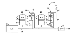
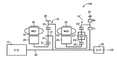
図1は、本発明が好適に適用されるハイブリッド車両用駆動装置10(以下、単に駆動装置10という)の構成を説明する骨子図である。この図1に示すように、本実施例の駆動装置10は、例えばFF(前置エンジン前輪駆動)型車両等に好適に用いられる横置き用の装置であり、主動力源であるエンジン12、第1電動機MG1、第2電動機MG2、第1差動機構としての第1遊星歯車装置14、及び第2差動機構としての第2遊星歯車装置16を共通の中心軸CE上に備えて構成されている。前記駆動装置10は、中心軸CEに対して略対称的に構成されており、図1においては中心線の下半分を省略して図示している。以下の各実施例についても同様である。
FIG. 1 is a skeleton diagram illustrating the configuration of a hybrid vehicle drive device 10 (hereinafter simply referred to as drive device 10) to which the present invention is preferably applied. As shown in FIG. 1, the drive device 10 of the present embodiment is a device for horizontal use that is preferably used in, for example, an FF (front engine front wheel drive) type vehicle and the like, and an engine 12, which is a main power source, The first electric motor MG1, the second electric motor MG2, the first planetary gear device 14 as a first differential mechanism, and the second planetary gear device 16 as a second differential mechanism are provided on a common central axis CE. ing. The driving device 10 is configured substantially symmetrically with respect to the central axis CE, and the lower half of the central line is omitted in FIG. The same applies to each of the following embodiments.
前記エンジン12は、例えば、気筒内噴射されるガソリン等の燃料の燃焼によって駆動力を発生させるガソリンエンジン等の内燃機関である。前記第1電動機MG1及び第2電動機MG2は、好適には、何れも駆動力を発生させるモータ(発動機)及び反力を発生させるジェネレータ(発電機)としての機能を有する所謂モータジェネレータであり、それぞれのステータ(固定子)18、22が非回転部材であるハウジング(ケース)26に固設されると共に、各ステータ18、22の内周側にロータ(回転子)20、24を備えて構成されている。
The engine 12 is, for example, an internal combustion engine such as a gasoline engine that generates driving force by combustion of fuel such as gasoline injected in a cylinder. The first electric motor MG1 and the second electric motor MG2 are preferably so-called motor generators each having a function as a motor (engine) for generating driving force and a generator (generator) for generating reaction force. Each stator (stator) 18, 22 is fixed to a housing (case) 26 that is a non-rotating member, and the rotor (rotor) 20, 24 is provided on the inner peripheral side of each stator 18, 22. Has been.
前記第1遊星歯車装置14は、ギヤ比がρ1であるシングルピニオン型の遊星歯車装置であり、第1回転要素としてのサンギヤS1、ピニオンギヤP1を自転及び公転可能に支持する第2回転要素としてのキャリアC1、及びピニオンギヤP1を介してサンギヤS1と噛み合う第3回転要素としてのリングギヤR1を回転要素(要素)として備えている。前記第2遊星歯車装置16は、ギヤ比がρ2であるシングルピニオン型の遊星歯車装置であり、第1回転要素としてのサンギヤS2、ピニオンギヤP2を自転及び公転可能に支持する第2回転要素としてのキャリアC2、及びピニオンギヤP2を介してサンギヤS2と噛み合う第3回転要素としてのリングギヤR2を回転要素(要素)として備えている。
The first planetary gear unit 14 is a single pinion type planetary gear unit having a gear ratio of ρ1, and serves as a second rotating element that supports the sun gear S1 and the pinion gear P1 as the first rotating element so as to be capable of rotating and revolving. A ring gear R1 as a third rotating element that meshes with the sun gear S1 via the carrier C1 and the pinion gear P1 is provided as a rotating element (element). The second planetary gear device 16 is a single pinion type planetary gear device having a gear ratio of ρ2, and serves as a second rotating element that supports the sun gear S2 and the pinion gear P2 as the first rotating element so as to be capable of rotating and revolving. A ring gear R2 as a third rotating element that meshes with the sun gear S2 via the carrier C2 and the pinion gear P2 is provided as a rotating element (element).
前記第1遊星歯車装置14のサンギヤS1は、前記第1電動機MG1のロータ20に連結されている。前記第1遊星歯車装置14のキャリアC1は、前記エンジン12のクランク軸12aと一体的に回転させられる入力軸28に連結されている。この入力軸28は、前記中心軸CEを軸心とするものであり、以下の実施例において、特に区別しない場合には、この中心軸CEの軸心の方向を軸方向(軸心方向)という。前記第1遊星歯車装置14のリングギヤR1は、出力回転部材である出力歯車30に連結されると共に、前記第2遊星歯車装置16のリングギヤR2と相互に連結されている。前記第2遊星歯車装置16のサンギヤS2は、前記第2電動機MG2のロータ24に連結されている。
The sun gear S1 of the first planetary gear unit 14 is connected to the rotor 20 of the first electric motor MG1. The carrier C1 of the first planetary gear unit 14 is connected to an input shaft 28 that is rotated integrally with the crankshaft 12a of the engine 12. The input shaft 28 is centered on the central axis CE. In the following embodiments, the direction of the central axis of the central axis CE is referred to as an axial direction (axial direction) unless otherwise distinguished. . The ring gear R1 of the first planetary gear device 14 is connected to an output gear 30 that is an output rotating member, and is also connected to the ring gear R2 of the second planetary gear device 16. The sun gear S2 of the second planetary gear device 16 is connected to the rotor 24 of the second electric motor MG2.
前記出力歯車30から出力された駆動力は、図示しない差動歯車装置及び車軸等を介して図示しない左右一対の駆動輪へ伝達される。一方、車両の走行路面から駆動輪に対して入力されるトルクは、前記差動歯車装置及び車軸等を介して前記出力歯車30から前記駆動装置10へ伝達(入力)される。前記入力軸28における前記エンジン12と反対側の端部には、例えばベーンポンプ等の機械式オイルポンプ32が連結されており、前記エンジン12の駆動に伴い後述する油圧制御回路60等の元圧とされる油圧が出力されるようになっている。このオイルポンプ32に加えて、電気エネルギにより駆動される電動式オイルポンプが設けられたものであってもよい。
The driving force output from the output gear 30 is transmitted to a pair of left and right driving wheels (not shown) via a differential gear device and an axle (not shown). On the other hand, torque input to the drive wheels from the road surface of the vehicle is transmitted (input) from the output gear 30 to the drive device 10 via the differential gear device and the axle. A mechanical oil pump 32 such as a vane pump is connected to an end portion of the input shaft 28 opposite to the engine 12, and an original pressure of a hydraulic control circuit 60 or the like to be described later when the engine 12 is driven. The hydraulic pressure is output. In addition to the oil pump 32, an electric oil pump driven by electric energy may be provided.
前記第1遊星歯車装置14のキャリアC1と前記第2遊星歯車装置16のキャリアC2との間には、それらキャリアC1とC2との間を選択的に係合させる(キャリアC1とC2との間を断接する)クラッチCLが設けられている。前記第2遊星歯車装置16のキャリアC2と非回転部材である前記ハウジング26との間には、そのハウジング26に対して前記キャリアC2を選択的に係合(固定)させるブレーキBKが設けられている。これらのクラッチCL及びブレーキBKは、好適には、何れも油圧制御回路60から供給される油圧に応じて係合状態が制御される(係合乃至解放させられる)油圧式係合装置であり、例えば、湿式多板型の摩擦係合装置等が好適に用いられるが、噛合式の係合装置すなわち所謂ドグクラッチ(噛合クラッチ)であってもよい。更には、電磁式クラッチや磁粉式クラッチ等、電子制御装置40から供給される電気的な指令に応じて係合状態が制御される(係合乃至解放させられる)ものであってもよい。
The carrier C1 of the first planetary gear device 14 and the carrier C2 of the second planetary gear device 16 are selectively engaged between the carriers C1 and C2 (between the carriers C1 and C2). A clutch CL is provided. A brake BK for selectively engaging (fixing) the carrier C2 with respect to the housing 26 is provided between the carrier C2 of the second planetary gear device 16 and the housing 26 which is a non-rotating member. Yes. The clutch CL and the brake BK are preferably hydraulic engagement devices whose engagement states are controlled (engaged or released) according to the hydraulic pressure supplied from the hydraulic control circuit 60. For example, a wet multi-plate friction engagement device or the like is preferably used, but a meshing engagement device, that is, a so-called dog clutch (meshing clutch) may be used. Furthermore, an engagement state may be controlled (engaged or released) according to an electrical command supplied from the electronic control device 40, such as an electromagnetic clutch or a magnetic powder clutch.
図1に示すように、前記駆動装置10において、前記第1遊星歯車装置14及び第2遊星歯車装置16は、それぞれ前記入力軸28と同軸上(中心軸CE上)に配置されており、且つ、前記中心軸CEの軸方向において対向する位置に配置されている。すなわち、前記中心軸CEの軸方向に関して、前記第1遊星歯車装置14は、前記第2遊星歯車装置16に対して前記エンジン12側に配置されている。前記中心軸CEの軸方向に関して、前記第1電動機MG1は、前記第1遊星歯車装置14に対して前記エンジン12側に配置されている。前記中心軸CEの軸方向に関して、前記第2電動機MG1は、前記第2遊星歯車装置16に対して前記エンジン12の反対側に配置されている。すなわち、前記第1電動機MG1、第2電動機MG2は、前記中心軸CEの軸方向に関して、前記第1遊星歯車装置14及び第2遊星歯車装置16を間に挟んで対向する位置に配置されている。すなわち、前記駆動装置10においては、前記中心軸CEの軸方向において、前記エンジン12側から前記第1電動機MG1、第1遊星歯車装置14、クラッチCL、第2遊星歯車装置16、ブレーキBK、第2電動機MG2の順でそれらの構成が同軸上に配置されている。
As shown in FIG. 1, in the driving device 10, the first planetary gear device 14 and the second planetary gear device 16 are arranged coaxially with the input shaft 28 (on the central axis CE), and , Are arranged at positions facing each other in the axial direction of the central axis CE. That is, with respect to the axial direction of the central axis CE, the first planetary gear device 14 is disposed on the engine 12 side with respect to the second planetary gear device 16. With respect to the axial direction of the central axis CE, the first electric motor MG1 is disposed on the engine 12 side with respect to the first planetary gear unit 14. With respect to the axial direction of the central axis CE, the second electric motor MG1 is disposed on the opposite side of the engine 12 with respect to the second planetary gear device 16. That is, the first electric motor MG1 and the second electric motor MG2 are arranged at positions facing each other with the first planetary gear device 14 and the second planetary gear device 16 interposed therebetween with respect to the axial direction of the central axis CE. . That is, in the drive device 10, in the axial direction of the central axis CE, the first electric motor MG1, the first planetary gear device 14, the clutch CL, the second planetary gear device 16, the brake BK, Those components are arranged on the same axis in the order of the two electric motors MG2.
図2は、前記駆動装置10の駆動を制御するためにその駆動装置10に備えられた制御系統の要部を説明する図である。この図2に示す電子制御装置40は、CPU、ROM、RAM、及び入出力インターフェイス等を含んで構成され、RAMの一時記憶機能を利用しつつROMに予め記憶されたプログラムに従って信号処理を実行する所謂マイクロコンピュータであり、前記エンジン12の駆動制御や、前記第1電動機MG1及び第2電動機MG2に関するハイブリッド駆動制御をはじめとする前記駆動装置10の駆動に係る各種制御を実行する。すなわち、本実施例においては、前記電子制御装置40が前記駆動装置10の適用されたハイブリッド車両の駆動制御装置に相当する。この電子制御装置40は、前記エンジン12の出力制御用や前記第1電動機MG1及び第2電動機MG2の作動制御用といったように、必要に応じて各制御毎に個別の制御装置として構成される。
FIG. 2 is a diagram for explaining a main part of a control system provided in the driving device 10 in order to control the driving of the driving device 10. The electronic control unit 40 shown in FIG. 2 includes a CPU, a ROM, a RAM, an input / output interface, and the like, and executes signal processing in accordance with a program stored in advance in the ROM while using a temporary storage function of the RAM. The microcomputer is a so-called microcomputer, and executes various controls related to driving of the drive device 10 including drive control of the engine 12 and hybrid drive control related to the first electric motor MG1 and the second electric motor MG2. That is, in this embodiment, the electronic control device 40 corresponds to a drive control device for a hybrid vehicle to which the drive device 10 is applied. The electronic control device 40 is configured as an individual control device for each control as required, such as for output control of the engine 12 and for operation control of the first electric motor MG1 and the second electric motor MG2.
図2に示すように、前記電子制御装置40には、前記駆動装置10の各部に設けられたセンサやスイッチ等から各種信号が供給されるように構成されている。すなわち、アクセル開度センサ42により運転者の出力要求量に対応する図示しないアクセルペダルの操作量であるアクセル開度ACCを表す信号、エンジン回転速度センサ44により前記エンジン12の回転速度であるエンジン回転速度NEを表す信号、MG1回転速度センサ46により前記第1電動機MG1の回転速度NMG1を表す信号、MG2回転速度センサ48により前記第2電動機MG2の回転速度NMG2を表す信号、出力回転速度センサ50により車速Vに対応する前記出力歯車30の回転速度NOUTを表す信号、クランク位置センサ52により前記エンジン12のクランク軸12a(図1を参照)のクランク位置(クランクポジション)PCRすなわちそのクランク軸12aの回転角度位置を表す信号、エンジン温度センサ53により前記エンジン12の冷却水温乃至油温等、そのエンジン12の温度ThEを表す信号、及びバッテリSOCセンサ54によりバッテリ55の充電容量(充電状態)SOCを表す信号等が、それぞれ上記電子制御装置40に供給される。前記クランク位置センサ52は、前記第1電動機MG1の電気角等から前記エンジン12のクランク位置PCRを検出するものであってもよい。
As shown in FIG. 2, the electronic control device 40 is configured to be supplied with various signals from sensors, switches, and the like provided in each part of the driving device 10. That is, a signal representing an accelerator opening degree A CC which is an operation amount of an accelerator pedal (not shown) corresponding to a driver's output request amount by the accelerator opening sensor 42, and an engine which is the rotation speed of the engine 12 by the engine rotation speed sensor 44. signal representative of the rotational speed N E, a signal indicative of the rotational speed N MG1 of the first electric motor MG1 by MG1 rotational speed sensor 46, a signal indicative of the rotational speed N MG2 of the second electric motor MG2 by MG2 rotational speed sensor 48, output rotation signal representative of the rotational speed N OUT of the output gear 30 by the speed sensor 50 corresponding to the vehicle speed V, the said crank position of the crankshaft 12a of the engine 12 (see FIG. 1) (a crank position) P CR i.e. by the crank position sensor 52 A signal indicating the rotational angle position of the crankshaft 12a, by the engine temperature sensor 53 Coolant temperature to oil temperature or the like of the serial engine 12, a signal representative of the temperature Th E of the engine 12, and a signal or the like indicative of a charged capacity (charged state) SOC of the battery 55 by the battery SOC sensor 54, each of the above electronic control unit 40 To be supplied. The crank position sensor 52, the electrical angle and the like of the first electric motor MG1 may be used to detect the crank position P CR of the engine 12.
前記電子制御装置40からは、前記駆動装置10の各部に作動指令が出力されるように構成されている。すなわち、前記エンジン12の出力を制御するエンジン出力制御指令として、燃料噴射装置による吸気配管等への燃料供給量を制御する燃料噴射量信号、点火装置による前記エンジン12の点火時期(点火タイミング)を指令する点火信号、及び電子スロットル弁のスロットル弁開度θTHを操作するためにスロットルアクチュエータへ供給される電子スロットル弁駆動信号等が、そのエンジン12の出力を制御するエンジン制御装置56へ出力される。前記第1電動機MG1及び第2電動機MG2の作動を指令する指令信号がインバータ58へ出力され、そのインバータ58を介して前記バッテリ55からその指令信号に応じた電気エネルギが前記第1電動機MG1及び第2電動機MG2に供給されてそれら第1電動機MG1及び第2電動機MG2の出力(トルク)が制御される。前記第1電動機MG1及び第2電動機MG2により発電された電気エネルギが前記インバータ58を介して前記バッテリ55に供給され、そのバッテリ55に蓄積されるようになっている。すなわち、前記駆動装置10においては、前記バッテリ55が駆動用バッテリに対応する。前記クラッチCL、ブレーキBKの係合状態を制御する指令信号が油圧制御回路60に備えられたリニアソレノイド弁等の電磁制御弁へ供給され、それら電磁制御弁から出力される油圧が制御されることで前記クラッチCL、ブレーキBKの係合状態が制御されるようになっている。
The electronic control device 40 is configured to output an operation command to each part of the driving device 10. That is, as an engine output control command for controlling the output of the engine 12, a fuel injection amount signal for controlling a fuel supply amount to an intake pipe or the like by the fuel injection device, and an ignition timing (ignition timing) of the engine 12 by the ignition device. An ignition signal to be commanded, an electronic throttle valve drive signal supplied to the throttle actuator for operating the throttle valve opening θ TH of the electronic throttle valve, and the like are output to an engine control device 56 that controls the output of the engine 12. The A command signal for commanding the operation of the first motor MG1 and the second motor MG2 is output to the inverter 58, and electric energy corresponding to the command signal is transmitted from the battery 55 via the inverter 58 to the first motor MG1 and the second motor MG2. The two electric motors MG2 are supplied to control the outputs (torques) of the first electric motor MG1 and the second electric motor MG2. Electric energy generated by the first electric motor MG1 and the second electric motor MG2 is supplied to the battery 55 via the inverter 58 and stored in the battery 55. That is, in the driving device 10, the battery 55 corresponds to a driving battery. A command signal for controlling the engagement state of the clutch CL and the brake BK is supplied to an electromagnetic control valve such as a linear solenoid valve provided in the hydraulic control circuit 60, and the hydraulic pressure output from the electromagnetic control valve is controlled. Thus, the engagement state of the clutch CL and the brake BK is controlled.
前記駆動装置10は、前記第1電動機MG1及び第2電動機MG2を介して運転状態が制御されることにより、入力回転速度と出力回転速度の差動状態が制御される電気式差動部として機能する。例えば、前記第1電動機MG1により発電された電気エネルギを前記インバータ58を介して前記バッテリ55や第2電動機MG2へ供給する。これにより、前記エンジン12の動力の主要部は機械的に前記出力歯車30へ伝達される一方、その動力の一部は前記第1電動機MG1の発電のために消費されてそこで電気エネルギに変換され、前記インバータ58を通してその電気エネルギが前記第2電動機MG2へ供給される。そして、その第2電動機MG2が駆動されて第2電動機MG2から出力された動力が前記出力歯車30へ伝達される。この電気エネルギの発生から第2電動機MG2で消費されるまでに関連する機器により、前記エンジン12の動力の一部を電気エネルギに変換し、その電気エネルギを機械的エネルギに変換するまでの電気パスが構成される。
The drive device 10 functions as an electric differential unit that controls the differential state between the input rotation speed and the output rotation speed by controlling the operation state via the first electric motor MG1 and the second electric motor MG2. To do. For example, the electric energy generated by the first electric motor MG1 is supplied to the battery 55 and the second electric motor MG2 via the inverter 58. As a result, the main part of the power of the engine 12 is mechanically transmitted to the output gear 30, while a part of the power is consumed for power generation of the first electric motor MG 1 and is converted into electric energy there. The electric energy is supplied to the second electric motor MG2 through the inverter 58. Then, the second electric motor MG2 is driven, and the power output from the second electric motor MG2 is transmitted to the output gear 30. Electrical path from conversion of part of the power of the engine 12 into electrical energy and conversion of the electrical energy into mechanical energy by related equipment from the generation of the electrical energy to consumption by the second electric motor MG2. Is configured.
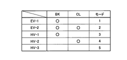
以上のように構成された駆動装置10が適用されたハイブリッド車両においては、前記エンジン12、第1電動機MG1、及び第2電動機MG2の駆動状態、及び前記クラッチCL、ブレーキBKの係合状態等に応じて、複数の走行モードの何れかが選択的に成立させられる。図3は、前記駆動装置10において成立させられる5種類の走行モードそれぞれにおける前記クラッチCL、ブレーキBKの係合状態を示す係合表であり、係合を「○」で、解放を空欄でそれぞれ示している。この図3に示す走行モード「EV-1」、「EV-2」は、何れも前記エンジン12の運転が停止させられると共に、前記第1電動機MG1及び第2電動機MG2の少なくとも一方を走行用の駆動源として用いるEV走行モードである。「HV-1」、「HV-2」、「HV-3」は、何れも前記エンジン12を例えば走行用の駆動源として駆動させると共に、前記第1電動機MG1及び第2電動機MG2により必要に応じて駆動乃至発電等を行うハイブリッド走行モードである。このハイブリッド走行モードにおいて、前記第1電動機MG1及び第2電動機MG2の少なくとも一方により反力を発生させるものであってもよく、無負荷の状態で空転させるものであってもよい。
In the hybrid vehicle to which the drive device 10 configured as described above is applied, the driving state of the engine 12, the first electric motor MG1, and the second electric motor MG2 and the engagement state of the clutch CL and the brake BK are set. In response, one of the plurality of travel modes is selectively established. FIG. 3 is an engagement table showing the engagement states of the clutch CL and the brake BK in each of the five types of travel modes established in the drive device 10, wherein the engagement is “◯” and the release is blank. Show. In each of the travel modes “EV-1” and “EV-2” shown in FIG. 3, the operation of the engine 12 is stopped, and at least one of the first electric motor MG1 and the second electric motor MG2 is used for traveling. This is an EV travel mode used as a drive source. “HV-1”, “HV-2”, and “HV-3” all drive the engine 12 as a driving source for traveling, for example, and the first motor MG1 and the second motor MG2 as required. This is a hybrid travel mode for driving or generating power. In this hybrid travel mode, a reaction force may be generated by at least one of the first electric motor MG1 and the second electric motor MG2, or may be idled in an unloaded state.
図3に示すように、前記駆動装置10においては、前記エンジン12の運転が停止させられると共に、前記第1電動機MG1及び第2電動機MG2の少なくとも一方を走行用の駆動源として用いるEV走行モードにおいて、前記ブレーキBKが係合されると共に前記クラッチCLが解放されることでモード1(走行モード1)である「EV-1」が、前記ブレーキBK及びクラッチCLが共に係合されることでモード2(走行モード2)である「EV-2」がそれぞれ成立させられる。前記エンジン12を例えば走行用の駆動源として駆動させると共に、前記第1電動機MG1及び第2電動機MG2により必要に応じて駆動乃至発電等を行うハイブリッド走行モードにおいて、前記ブレーキBKが係合されると共に前記クラッチCLが解放されることでモード3(走行モード3)である「HV-1」が、前記ブレーキBKが解放されると共に前記クラッチCLが係合されることでモード4(走行モード4)である「HV-2」が、前記ブレーキBK及びクラッチCLが共に解放されることでモード5(走行モード5)である「HV-3」がそれぞれ成立させられる。
As shown in FIG. 3, in the driving apparatus 10, the operation of the engine 12 is stopped, and in the EV traveling mode in which at least one of the first electric motor MG <b> 1 and the second electric motor MG <b> 2 is used as a driving source for traveling. When the brake BK is engaged and the clutch CL is disengaged, mode 1 (travel mode 1) is “EV-1”, and when the brake BK and the clutch CL are both engaged, the mode is 2 (travel mode 2), “EV-2”, is established. In the hybrid traveling mode in which the engine 12 is driven as a driving source for traveling, for example, and the first electric motor MG1 and the second electric motor MG2 are driven or generated as necessary, the brake BK is engaged. “HV-1” which is mode 3 (travel mode 3) by releasing the clutch CL, and mode 4 (travel mode 4) by releasing the brake BK and engaging the clutch CL. "HV-2" is established, and "HV-3" which is mode 5 (travel mode 5) is established by releasing both the brake BK and the clutch CL.
図4~図7は、前記駆動装置10(第1遊星歯車装置14及び第2遊星歯車装置16)において、前記クラッチCL及びブレーキBKそれぞれの係合状態に応じて連結状態が異なる各回転要素の回転速度の相対関係を直線上で表すことができる共線図を示しており、横軸方向において前記第1遊星歯車装置14及び第2遊星歯車装置16のギヤ比ρの相対関係を示し、縦軸方向において相対的回転速度を示す二次元座標である。車両前進時における前記出力歯車30の回転方向を正の方向(正回転)として各回転速度を表している。横線X1は回転速度零を示している。縦線Y1~Y4は、左から順に実線Y1が前記第1遊星歯車装置14のサンギヤS1(第1電動機MG1)、破線Y2が前記第2遊星歯車装置16のサンギヤS2(第2電動機MG2)、実線Y3が前記第1遊星歯車装置14のキャリアC1(エンジン12)、破線Y3′が前記第2遊星歯車装置16のキャリアC2、実線Y4が前記第1遊星歯車装置14のリングギヤR1(出力歯車30)、破線Y4′が前記第2遊星歯車装置16のリングギヤR2それぞれの相対回転速度を示している。図4~図7においては、縦線Y3及びY3′、縦線Y4及びY4′をそれぞれ重ねて表している。ここで、前記リングギヤR1及びR2は相互に連結されているため、縦線Y4、Y4′にそれぞれ示すリングギヤR1及びR2の相対回転速度は等しい。
FIGS. 4 to 7 show the rotation elements of the driving device 10 (the first planetary gear device 14 and the second planetary gear device 16) that have different coupling states depending on the engagement states of the clutch CL and the brake BK. FIG. 2 shows a collinear chart that can represent the relative relationship of rotational speed on a straight line, showing the relative relationship of the gear ratio ρ of the first planetary gear device 14 and the second planetary gear device 16 in the horizontal axis direction, It is a two-dimensional coordinate which shows a relative rotational speed in an axial direction. The rotational speeds of the output gears 30 when the vehicle moves forward are represented as positive directions (positive rotations). A horizontal line X1 indicates zero rotation speed. In the vertical lines Y1 to Y4, in order from the left, the solid line Y1 indicates the sun gear S1 (first electric motor MG1) of the first planetary gear unit 14, the broken line Y2 indicates the sun gear S2 (second electric motor MG2) of the second planetary gear unit 16, The solid line Y3 is the carrier C1 (engine 12) of the first planetary gear unit 14, the broken line Y3 'is the carrier C2 of the second planetary gear unit 16, and the solid line Y4 is the ring gear R1 (output gear 30) of the first planetary gear unit 14. ), The broken line Y4 ′ indicates the relative rotational speed of each ring gear R2 of the second planetary gear unit 16. 4 to 7, the vertical lines Y3 and Y3 ′ and the vertical lines Y4 and Y4 ′ are overlaid. Here, since the ring gears R1 and R2 are connected to each other, the relative rotational speeds of the ring gears R1 and R2 indicated by the vertical lines Y4 and Y4 ′ are equal.
図4~図7においては、前記第1遊星歯車装置14における3つの回転要素の相対的な回転速度を実線L1で、前記第2遊星歯車装置16における3つの回転要素の相対的な回転速度を破線L2でそれぞれ示している。前記縦線Y1~Y4(Y2~Y4′)の間隔は、前記第1遊星歯車装置14及び第2遊星歯車装置16の各ギヤ比ρ1、ρ2に応じて定められている。すなわち、前記第1遊星歯車装置14における3つの回転要素に対応する縦線Y1、Y3、Y4に関して、サンギヤS1とキャリアC1との間が1に対応するものとされ、キャリアC1とリングギヤR1との間がρ1に対応するものとされる。前記第2遊星歯車装置16における3つの回転要素に対応する縦線Y2、Y3′、Y4′に関して、サンギヤS2とキャリアC2との間が1に対応するものとされ、キャリアC2とリングギヤR2との間がρ2に対応するものとされる。すなわち、前記駆動装置10において、好適には、前記第1遊星歯車装置14のギヤ比ρ1よりも前記第2遊星歯車装置16のギヤ比ρ2の方が大きい(ρ2>ρ1)。以下、図4~図7を用いて前記駆動装置10における各走行モードについて説明する。
4 to 7, the relative rotational speeds of the three rotating elements in the first planetary gear device 14 are indicated by a solid line L1, and the relative rotational speeds of the three rotating elements in the second planetary gear device 16 are indicated by solid lines L1. Each is indicated by a broken line L2. The intervals between the vertical lines Y1 to Y4 (Y2 to Y4 ′) are determined according to the gear ratios ρ1 and ρ2 of the first planetary gear device 14 and the second planetary gear device 16. That is, regarding the vertical lines Y1, Y3, Y4 corresponding to the three rotating elements in the first planetary gear device 14, the space between the sun gear S1 and the carrier C1 corresponds to 1, and the carrier C1 and the ring gear R1 The interval corresponds to ρ1. Regarding the vertical lines Y2, Y3 ', Y4' corresponding to the three rotating elements in the second planetary gear device 16, the space between the sun gear S2 and the carrier C2 corresponds to 1, and the carrier C2 and the ring gear R2 The interval corresponds to ρ2. That is, in the drive device 10, the gear ratio ρ2 of the second planetary gear device 16 is preferably larger than the gear ratio ρ1 of the first planetary gear device 14 (ρ2> ρ1). Hereinafter, each traveling mode in the driving apparatus 10 will be described with reference to FIGS.
図3に示す「EV-1」は、前記駆動装置10におけるモード1(走行モード1)に相当するものであり、好適には、前記エンジン12の運転が停止させられると共に、前記第2電動機MG2が走行用の駆動源として用いられるEV走行モードである。図4は、このモード1に対応する共線図であり、この共線図を用いて説明すれば、前記クラッチCLが解放されることで前記第1遊星歯車装置14のキャリアC1と前記第2遊星歯車装置16のキャリアC2との相対回転が可能とされている。前記ブレーキBKが係合されることで前記第2遊星歯車装置16のキャリアC2が非回転部材である前記ハウジング26に対して連結(固定)され、その回転速度が零とされている。このモード1においては、前記第2遊星歯車装置16において、前記サンギヤS2の回転方向と前記リングギヤR2の回転方向とが逆方向となり、前記第2電動機MG2により負のトルク(負の方向のトルク)が出力されると、そのトルクにより前記リングギヤR2すなわち出力歯車30は正の方向に回転させられる。すなわち、前記第2電動機MG2により負のトルクを出力させることにより、前記駆動装置10の適用されたハイブリッド車両を前進走行させることができる。この場合において、好適には、前記第1電動機MG1は空転させられる。このモード1では、前記キャリアC1及びC2の相対回転が許容されると共に、そのキャリアC2が非回転部材に連結された所謂THS(Toyota Hybrid System)を搭載した車両におけるEV走行と同様のEV走行制御を行うことができる。
“EV-1” shown in FIG. 3 corresponds to mode 1 (travel mode 1) in the drive device 10, and preferably the operation of the engine 12 is stopped and the second electric motor MG2 is stopped. Is an EV traveling mode used as a driving source for traveling. FIG. 4 is a collinear diagram corresponding to this mode 1, and will be described using this collinear diagram. When the clutch CL is released, the carrier C1 and the second planetary gear device 14 of the first planetary gear unit 14 are disengaged. The planetary gear device 16 can rotate relative to the carrier C2. Engagement of the brake BK causes the carrier C2 of the second planetary gear device 16 to be connected (fixed) to the housing 26, which is a non-rotating member, so that its rotational speed is zero. In this mode 1, in the second planetary gear device 16, the rotation direction of the sun gear S2 and the rotation direction of the ring gear R2 are opposite to each other, and negative torque (torque in the negative direction) is generated by the second electric motor MG2. Is output, the torque causes the ring gear R2, that is, the output gear 30, to rotate in the positive direction. That is, by outputting negative torque by the second electric motor MG2, the hybrid vehicle to which the drive device 10 is applied can be caused to travel forward. In this case, preferably, the first electric motor MG1 is idled. In this mode 1, the relative rotation of the carriers C1 and C2 is allowed, and EV travel control similar to EV travel in a vehicle equipped with a so-called THS (Toyota Hybrid System) in which the carrier C2 is connected to a non-rotating member. It can be performed.
図3に示す「EV-2」は、前記駆動装置10におけるモード2(走行モード2)に相当するものであり、好適には、前記エンジン12の運転が停止させられると共に、前記第1電動機MG1及び第2電動機MG2の少なくとも一方が走行用の駆動源として用いられるEV走行モードである。図5は、このモード2に対応する共線図であり、この共線図を用いて説明すれば、前記クラッチCLが係合されることで前記第1遊星歯車装置14のキャリアC1と前記第2遊星歯車装置16のキャリアC2との相対回転が不能とされている。更に、前記ブレーキBKが係合されることで前記第2遊星歯車装置16のキャリアC2及びそのキャリアC2に係合された前記第1遊星歯車装置14のキャリアC1が非回転部材である前記ハウジング26に対して連結(固定)され、その回転速度が零とされている。このモード2においては、前記第1遊星歯車装置14において、前記サンギヤS1の回転方向と前記リングギヤR1の回転方向とが逆方向となると共に、前記第2遊星歯車装置16において、前記サンギヤS2の回転方向と前記リングギヤR2の回転方向とが逆方向となる。すなわち、前記第1電動機MG1乃至前記第2電動機MG2により負のトルク(負の方向のトルク)が出力されると、そのトルクにより前記リングギヤR1及びR2すなわち出力歯車30は正の方向に回転させられる。すなわち、前記第1電動機MG1及び第2電動機MG2の少なくとも一方により負のトルクを出力させることにより、前記駆動装置10の適用されたハイブリッド車両を前進走行させることができる。
“EV-2” shown in FIG. 3 corresponds to mode 2 (traveling mode 2) in the driving apparatus 10, and preferably the operation of the engine 12 is stopped and the first electric motor MG1 is stopped. In addition, this is an EV traveling mode in which at least one of the second electric motor MG2 is used as a driving source for traveling. FIG. 5 is a collinear diagram corresponding to this mode 2. If the collinear diagram is used to explain, the carrier C1 of the first planetary gear device 14 and the first planetary gear device 14 are engaged by engaging the clutch CL. The relative rotation of the two planetary gear unit 16 with the carrier C2 is disabled. Further, when the brake BK is engaged, the carrier C2 of the second planetary gear device 16 and the carrier C1 of the first planetary gear device 14 engaged with the carrier C2 are non-rotating members. Are connected (fixed) to each other and their rotational speed is zero. In this mode 2, the rotation direction of the sun gear S1 is opposite to the rotation direction of the ring gear R1 in the first planetary gear device 14, and the rotation of the sun gear S2 is reversed in the second planetary gear device 16. The direction and the rotation direction of the ring gear R2 are opposite to each other. That is, when negative torque (torque in the negative direction) is output from the first electric motor MG1 to the second electric motor MG2, the ring gears R1 and R2, that is, the output gear 30 are rotated in the positive direction by the torque. . That is, the hybrid vehicle to which the drive device 10 is applied can be caused to travel forward by outputting negative torque by at least one of the first electric motor MG1 and the second electric motor MG2.
前記モード2においては、前記第1電動機MG1及び第2電動機MG2の少なくとも一方により発電を行う形態を成立させることもできる。この形態においては、前記第1電動機MG1及び第2電動機MG2の一方或いは両方により走行用の駆動力(トルク)を分担して発生させることが可能となり、各電動機を効率の良い動作点で動作させたり、熱によるトルク制限等の制約を緩和する走行等が可能となる。更に、前記バッテリ55の充電状態が満充電の場合等、回生による発電が許容されない場合に、前記第1電動機MG1及び第2電動機MG2の一方或いは両方を空転させることも可能である。すなわち、前記モード2においては、幅広い走行条件においてEV走行を行うことや、長時間継続してEV走行を行うことが可能となる。従って、前記モード2は、プラグインハイブリッド車両等、EV走行を行う割合が高いハイブリッド車両において好適に採用される。
In the mode 2, it is possible to establish a mode in which power generation is performed by at least one of the first electric motor MG1 and the second electric motor MG2. In this form, it becomes possible to share and generate driving force (torque) for traveling by one or both of the first electric motor MG1 and the second electric motor MG2, and each electric motor is operated at an efficient operating point. Or running that relaxes restrictions such as torque limitation due to heat. Further, when power generation by regeneration is not allowed, such as when the state of charge of the battery 55 is fully charged, it is possible to idle one or both of the first electric motor MG1 and the second electric motor MG2. That is, in the mode 2, it is possible to perform EV traveling under a wide range of traveling conditions, or to perform EV traveling continuously for a long time. Therefore, the mode 2 is suitably employed in a hybrid vehicle having a high EV traveling ratio such as a plug-in hybrid vehicle.
図3に示す「HV-1」は、前記駆動装置10におけるモード3(走行モード3)に相当するものであり、好適には、前記エンジン12が駆動されて走行用の駆動源として用いられると共に、必要に応じて前記第1電動機MG1及び第2電動機MG2による駆動乃至発電が行われるハイブリッド走行モードである。図4の共線図は、このモード3に対応するものでもあり、この共線図を用いて説明すれば、前記クラッチCLが解放されることで前記第1遊星歯車装置14のキャリアC1と前記第2遊星歯車装置16のキャリアC2との相対回転が可能とされている。前記ブレーキBKが係合されることで前記第2遊星歯車装置16のキャリアC2が非回転部材である前記ハウジング26に対して連結(固定)され、その回転速度が零とされている。このモード3においては、前記エンジン12が駆動させられ、その出力トルクにより前記出力歯車30が回転させられる。この際、前記第1遊星歯車装置14において、前記第1電動機MG1により反力トルクを出力させることで、前記エンジン12からの出力の前記出力歯車30への伝達が可能とされる。前記第2遊星歯車装置16においては、前記ブレーキBKが係合されていることで、前記サンギヤS2の回転方向と前記リングギヤR2の回転方向とが逆方向となる。すなわち、前記第2電動機MG2により負のトルク(負の方向のトルク)が出力されると、そのトルクにより前記リングギヤR1及びR2すなわち出力歯車30は正の方向に回転させられる。
“HV-1” shown in FIG. 3 corresponds to mode 3 (traveling mode 3) in the driving device 10, and is preferably used as a driving source for traveling when the engine 12 is driven. This is a hybrid travel mode in which driving or power generation is performed by the first electric motor MG1 and the second electric motor MG2 as necessary. The collinear diagram of FIG. 4 also corresponds to this mode 3. If described using this collinear diagram, the carrier C1 of the first planetary gear device 14 and the carrier C1 are released by releasing the clutch CL. The second planetary gear device 16 can rotate relative to the carrier C2. Engagement of the brake BK causes the carrier C2 of the second planetary gear device 16 to be connected (fixed) to the housing 26, which is a non-rotating member, so that its rotational speed is zero. In mode 3, the engine 12 is driven, and the output gear 30 is rotated by the output torque. At this time, in the first planetary gear unit 14, the output torque from the engine 12 can be transmitted to the output gear 30 by causing the first electric motor MG 1 to output a reaction torque. In the second planetary gear unit 16, the rotation direction of the sun gear S2 and the rotation direction of the ring gear R2 are opposite because the brake BK is engaged. That is, when a negative torque (torque in the negative direction) is output by the second electric motor MG2, the ring gears R1 and R2, that is, the output gear 30 are rotated in the positive direction by the torque.
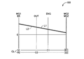
図3に示す「HV-2」は、前記駆動装置10におけるモード4(走行モード4)に相当するものであり、好適には、前記エンジン12が駆動されて走行用の駆動源として用いられると共に、必要に応じて前記第1電動機MG1及び第2電動機MG2による駆動乃至発電が行われるハイブリッド走行モードである。図6は、このモード4に対応する共線図であり、この共線図を用いて説明すれば、前記クラッチCLが係合されることで前記第1遊星歯車装置14のキャリアC1と前記第2遊星歯車装置16のキャリアC2との相対回転が不能とされており、前記キャリアC1及びC2が一体的に回転させられる1つの回転要素として動作する。前記リングギヤR1及びR2は相互に連結されていることで、それらリングギヤR1及びR2は一体的に回転させられる1つの回転要素として動作する。すなわち、前記モード4において、前記駆動装置10における前記第1遊星歯車装置14及び第2遊星歯車装置16における回転要素は、全体として4つの回転要素を備えた差動機構として機能する。すなわち、図6において紙面向かって左から順に示す4つの回転要素であるサンギヤS1(第1電動機MG1)、サンギヤS2(第2電動機MG2)、相互に連結されたキャリアC1及びC2(エンジン12)、相互に連結されたリングギヤR1及びR2(出力歯車30)の順に結合した複合スプリットモードとなる。
“HV-2” shown in FIG. 3 corresponds to mode 4 (travel mode 4) in the drive device 10, and is preferably used as a drive source for travel when the engine 12 is driven. This is a hybrid travel mode in which driving or power generation is performed by the first electric motor MG1 and the second electric motor MG2 as necessary. FIG. 6 is a collinear diagram corresponding to the mode 4, and will be described using this collinear diagram. When the clutch CL is engaged, the carrier C1 of the first planetary gear unit 14 and the first The relative rotation of the two planetary gear unit 16 with the carrier C2 is disabled, and the carriers C1 and C2 operate as one rotating element that is rotated integrally. Since the ring gears R1 and R2 are connected to each other, the ring gears R1 and R2 operate as one rotating element that is rotated integrally. That is, in the mode 4, the rotating elements in the first planetary gear device 14 and the second planetary gear device 16 in the driving device 10 function as a differential mechanism including four rotating elements as a whole. That is, four gears in order from the left in FIG. 6 are the sun gear S1 (first electric motor MG1), the sun gear S2 (second electric motor MG2), the carriers C1 and C2 (engine 12) connected to each other, A composite split mode is obtained in which ring gears R1 and R2 (output gear 30) connected to each other are connected in this order.
図6に示すように、前記モード4において、好適には、前記第1遊星歯車装置14及び第2遊星歯車装置16における各回転要素の共線図における並び順が、縦線Y1で示すサンギヤS1、縦線Y2で示すサンギヤS2、縦線Y3(Y3′)で示すキャリアC1及びC2、縦線Y4(Y4′)で示すリングギヤR1及びR2の順となる。前記第1遊星歯車装置14及び第2遊星歯車装置16それぞれのギヤ比ρ1、ρ2は、共線図において図6に示すように前記サンギヤS1に対応する縦線Y1と前記サンギヤS2に対応する縦線Y2とが上記の並び順となるように、すなわち縦線Y1と縦線Y3との間隔が、縦線Y2と縦線Y3′との間隔よりも広くなるように定められている。換言すれば、サンギヤS1、S2とキャリアC1、C2との間が1に対応するものとされ、キャリアC1、C2とリングギヤR1、R2との間がρ1、ρ2に対応することから、前記駆動装置10においては、前記第1遊星歯車装置14のギヤ比ρ1よりも前記第2遊星歯車装置16のギヤ比ρ2の方が大きい。
As shown in FIG. 6, in the mode 4, it is preferable that the arrangement order of the rotating elements in the first planetary gear device 14 and the second planetary gear device 16 in the alignment chart is a sun gear S1 indicated by a vertical line Y1. The sun gear S2 indicated by the vertical line Y2, the carriers C1 and C2 indicated by the vertical line Y3 (Y3 ′), and the ring gears R1 and R2 indicated by the vertical line Y4 (Y4 ′) are arranged in this order. The gear ratios ρ1 and ρ2 of the first planetary gear device 14 and the second planetary gear device 16 are respectively shown in FIG. 6 in the collinear diagram as a vertical line Y1 corresponding to the sun gear S1 and a vertical line corresponding to the sun gear S2. It is determined that the line Y2 is arranged in the above-described order, that is, the interval between the vertical line Y1 and the vertical line Y3 is wider than the interval between the vertical line Y2 and the vertical line Y3 ′. In other words, the sun gears S1 and S2 and the carriers C1 and C2 correspond to 1, and the carriers C1 and C2 and the ring gears R1 and R2 correspond to ρ1 and ρ2. 10, the gear ratio ρ2 of the second planetary gear device 16 is larger than the gear ratio ρ1 of the first planetary gear device 14.
前記モード4においては、前記クラッチCLが係合されることで前記第1遊星歯車装置14のキャリアC1と前記第2遊星歯車装置16のキャリアC2とが連結されており、それらキャリアC1及びC2が一体的に回転させられる。このため、前記エンジン12の出力に対して、前記第1電動機MG1及び第2電動機MG2の何れによっても反力を受けることができる。すなわち、前記エンジン12の駆動に際して、その反力を前記第1電動機MG1及び第2電動機MG2の一方乃至両方で分担して受けることが可能となり、効率の良い動作点で動作させたり、熱によるトルク制限等の制約を緩和する走行等が可能となる。例えば、前記第1電動機MG1及び第2電動機MG2のうち、効率良く動作できる方の電動機により優先的に反力を受けるように制御することで、効率の向上を図ることができる。更に、前記第1電動機MG1及び第2電動機MG2の何れかにおいて熱によるトルク制限がなされた場合に、トルク制限がなされていない電動機の回生乃至出力によって駆動力をアシストすることで、前記エンジン12の駆動に必要な反力を確保すること等が可能とされる。
In the mode 4, when the clutch CL is engaged, the carrier C1 of the first planetary gear device 14 and the carrier C2 of the second planetary gear device 16 are connected, and the carriers C1 and C2 are connected to each other. It can be rotated integrally. For this reason, the reaction force can be applied to the output of the engine 12 by either the first electric motor MG1 or the second electric motor MG2. That is, when the engine 12 is driven, the reaction force can be shared by one or both of the first electric motor MG1 and the second electric motor MG2, and the engine 12 can be operated at an efficient operating point, or the torque caused by heat. It is possible to run to ease restrictions such as restrictions. For example, the efficiency can be improved by controlling the first motor MG1 and the second motor MG2 to receive the reaction force preferentially by the motor that can operate efficiently. Further, when torque is limited by heat in either the first electric motor MG1 or the second electric motor MG2, the driving force is assisted by regeneration or output of an electric motor that is not torque limited, so that the engine 12 It is possible to ensure a reaction force necessary for driving.
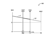
図3に示す「HV-3」は、前記駆動装置10におけるモード5(走行モード5)に相当するものであり、好適には、前記エンジン12が駆動されて走行用の駆動源として用いられると共に、必要に応じて前記第1電動機MG1による駆動乃至発電が行われるハイブリッド走行モードである。このモード5においては、前記第2電動機MG2を駆動系から切り離して前記エンジン12及び第1電動機MG1により駆動を行う等の形態を実現することができる。図7は、このモード5に対応する共線図であり、この共線図を用いて説明すれば、前記クラッチCLが解放されることで前記第1遊星歯車装置14のキャリアC1と前記第2遊星歯車装置16のキャリアC2との相対回転が可能とされている。前記ブレーキBKが解放されることで前記第2遊星歯車装置16のキャリアC2が非回転部材である前記ハウジング26に対して相対回転可能とされている。斯かる構成においては、前記第2電動機MG2を駆動系(動力伝達経路)から切り離して停止させておくことが可能である。
“HV-3” shown in FIG. 3 corresponds to mode 5 (traveling mode 5) in the driving device 10, and is preferably used as a driving source for traveling when the engine 12 is driven. This is a hybrid travel mode in which driving or power generation is performed by the first electric motor MG1 as necessary. In this mode 5, it is possible to realize a mode in which the second electric motor MG2 is disconnected from the drive system and driven by the engine 12 and the first electric motor MG1. FIG. 7 is a collinear diagram corresponding to this mode 5. If described with reference to this collinear diagram, the carrier C1 of the first planetary gear unit 14 and the second planetary gear device 14 are released by releasing the clutch CL. The planetary gear device 16 can rotate relative to the carrier C2. By releasing the brake BK, the carrier C2 of the second planetary gear device 16 can be rotated relative to the housing 26, which is a non-rotating member. In such a configuration, the second electric motor MG2 can be disconnected from the drive system (power transmission path) and stopped.
前記モード3においては、前記ブレーキBKが係合されているため、車両走行時において前記第2電動機MG2は前記出力歯車30(リングギヤR2)の回転に伴い常時回転させられる。斯かる形態において、比較的高回転となる領域では前記第2電動機MG2の回転速度が限界値(上限値)に達することや、前記リングギヤR2の回転速度が増速されて前記サンギヤS2に伝達されること等から、効率向上の観点からは比較的高車速時に前記第2電動機MG2を常時回転させておくことは必ずしも好ましくない。一方、前記モード5においては、比較的高車速時に前記第2電動機MG2を駆動系から切り離して前記エンジン12及び第1電動機MG1により駆動を行う形態を実現することで、その第2電動機MG2の駆動が不要な場合における引き摺り損失を低減できることに加え、その第2電動機MG2に許容される最高回転速度(上限値)に起因する最高車速への制約を解消すること等が可能とされる。
In the mode 3, since the brake BK is engaged, the second electric motor MG2 is always rotated with the rotation of the output gear 30 (ring gear R2) when the vehicle is traveling. In such a form, in the region where the rotation is relatively high, the rotation speed of the second electric motor MG2 reaches a limit value (upper limit value), or the rotation speed of the ring gear R2 is increased and transmitted to the sun gear S2. Therefore, from the viewpoint of improving efficiency, it is not always preferable to always rotate the second electric motor MG2 at a relatively high vehicle speed. On the other hand, in the mode 5, the second motor MG2 is driven by the engine 12 and the first motor MG1 by separating the second motor MG2 from the drive system at a relatively high vehicle speed, thereby driving the second motor MG2. In addition to being able to reduce drag loss when no is required, it is possible to eliminate restrictions on the maximum vehicle speed caused by the maximum rotation speed (upper limit value) allowed for the second electric motor MG2.
以上の説明から明らかなように、前記駆動装置10においては、前記エンジン12が駆動されて走行用の駆動源として用いられるハイブリッド走行に関して、前記クラッチCL及びブレーキBKの係合乃至解放の組み合わせにより、HV-1(モード3)、HV-2(モード4)、及びHV-3(モード5)の3つのモードを選択的に成立させることができる。これにより、例えば車両の車速や変速比等に応じてそれら3つのモードのうち最も伝達効率の高いモードを選択的に成立させることで、伝達効率の向上延いては燃費の向上を実現することができる。
As is clear from the above description, in the driving device 10, with respect to the hybrid driving used as the driving source for driving when the engine 12 is driven, the clutch CL and the brake BK are engaged or released in combination. Three modes of HV-1 (mode 3), HV-2 (mode 4), and HV-3 (mode 5) can be selectively established. Thereby, for example, by selectively establishing the mode with the highest transmission efficiency among these three modes according to the vehicle speed, the gear ratio, etc. of the vehicle, it is possible to improve the transmission efficiency and thus improve the fuel efficiency. it can.
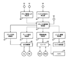
図8は、前記電子制御装置40に備えられた制御機能の要部を説明する機能ブロック線図である。この図8に示すエンジン駆動制御部70は、前記エンジン制御装置56を介して前記エンジン12の駆動を制御する。例えば、前記エンジン制御装置56を介して前記エンジン12の燃料噴射装置による吸気配管等への燃料供給量、点火装置による前記エンジン12の点火時期(点火タイミング)、及び電子スロットル弁のスロットル弁開度θTH等を制御することで、前記エンジン12により必要な出力すなわち目標トルク(目標エンジン出力)が得られるように制御する。前記エンジン12を駆動させると共に前記第1電動機MG1及び第2電動機MG2を走行用の駆動源として用いるハイブリッド走行モードでは、前記アクセル開度センサ42により検出されるアクセル開度ACC及び前記出力回転速度センサ50により検出される出力回転速度NOUTに対応する車速V等に基づいて前記駆動装置10(出力歯車30)から出力されるべき要求駆動力が算出され、前記エンジン12の出力トルク及び前記第1電動機MG1、第2電動機MG2の出力トルクにより斯かる要求駆動力が実現されるように、後述する電動機作動制御部72を介して前記第1電動機MG1及び第2電動機MG2の作動が制御されると共に、前記エンジン駆動制御部70を介して前記エンジン12の駆動が制御される。
FIG. 8 is a functional block diagram for explaining the main part of the control function provided in the electronic control unit 40. The engine drive control unit 70 shown in FIG. 8 controls the drive of the engine 12 via the engine control device 56. For example, the fuel supply amount to the intake pipe or the like by the fuel injection device of the engine 12 via the engine control device 56, the ignition timing (ignition timing) of the engine 12 by the ignition device, and the throttle valve opening of the electronic throttle valve By controlling θ TH and the like, the engine 12 is controlled so as to obtain a necessary output, that is, a target torque (target engine output). In the hybrid travel mode in which the engine 12 is driven and the first electric motor MG1 and the second electric motor MG2 are used as driving sources for traveling, the accelerator opening degree A CC detected by the accelerator opening degree sensor 42 and the output rotation speed are detected. Based on the vehicle speed V corresponding to the output rotational speed N OUT detected by the sensor 50, the required driving force to be output from the driving device 10 (output gear 30) is calculated, and the output torque of the engine 12 and the The operations of the first motor MG1 and the second motor MG2 are controlled via a motor operation control unit 72 described later so that the required driving force is realized by the output torque of the first motor MG1 and the second motor MG2. At the same time, the drive of the engine 12 is controlled via the engine drive control unit 70.
電動機作動制御部72は、前記インバータ58を介して前記第1電動機MG1及び第2電動機MG2の作動を制御する。具体的には、前記インバータ58を介して前記バッテリ55から前記第1電動機MG1、第2電動機MG2へ供給される電気エネルギを制御することによりそれら第1電動機MG1、第2電動機MG2により必要な出力すなわち目標トルク(目標電動機出力)が得られるように制御する。前記第1電動機MG1、第2電動機MG2により発電が行われる際には、それら第1電動機MG1、第2電動機MG2により発電された電気エネルギを前記インバータ58を介して前記バッテリ55に蓄積する。
The electric motor operation control unit 72 controls the operation of the first electric motor MG1 and the second electric motor MG2 via the inverter 58. Specifically, by controlling the electric energy supplied from the battery 55 to the first electric motor MG1 and the second electric motor MG2 via the inverter 58, the required output by the first electric motor MG1 and the second electric motor MG2. That is, control is performed so that a target torque (target motor output) is obtained. When electric power is generated by the first electric motor MG1 and the second electric motor MG2, electric energy generated by the first electric motor MG1 and the second electric motor MG2 is stored in the battery 55 via the inverter 58.
クラッチ係合制御部74は、前記油圧制御回路60を介して前記クラッチCLの係合状態を制御する。例えば、前記油圧制御回路60に備えられた、前記クラッチCLに対応する電磁制御弁からの出力圧を制御することで、そのクラッチCLの係合状態を係合乃至解放の間で切り替える制御を行う。ブレーキ係合制御部76は、前記油圧制御回路60を介して前記ブレーキBKの係合状態を制御する。例えば、前記油圧制御回路60に備えられた、前記ブレーキBKに対応する電磁制御弁からの出力圧を制御することで、そのブレーキBKの係合状態を係合乃至解放の間で切り替える制御を行う。前記クラッチ係合制御部74及びブレーキ係合制御部76は、基本的には、車両の走行状態等に応じて判定された走行モードが成立させられるように前記クラッチCL及びブレーキBKの係合状態を制御する。すなわち、前記モード1~5それぞれに関して、前述した図3に示す組み合わせで前記クラッチCL及びブレーキBKが係合乃至解放されるようにそれらの係合状態を制御する。
The clutch engagement control unit 74 controls the engagement state of the clutch CL via the hydraulic control circuit 60. For example, by controlling the output pressure from the electromagnetic control valve corresponding to the clutch CL provided in the hydraulic pressure control circuit 60, control is performed to switch the engagement state of the clutch CL between engagement and release. . The brake engagement control unit 76 controls the engagement state of the brake BK via the hydraulic control circuit 60. For example, by controlling the output pressure from the electromagnetic control valve corresponding to the brake BK provided in the hydraulic control circuit 60, control is performed to switch the engagement state of the brake BK between engagement and release. . The clutch engagement control unit 74 and the brake engagement control unit 76 are basically engaged with the clutch CL and the brake BK so that the travel mode determined according to the travel state of the vehicle is established. To control. That is, for each of the modes 1 to 5, the engagement state is controlled so that the clutch CL and the brake BK are engaged or released in the combination shown in FIG.
クランク位置調整制御部78は、車両の状態に応じて前記第1電動機MG1及び第2電動機MG2の少なくとも一方により前記エンジン12のクランク位置調整すなわち前記クランク軸12aの回転角度位置の調整を行う。好適には、前記エンジン12の停止状態からの始動に際して、その始動に先立って斯かるクランク位置調整を実行する。換言すれば、前記エンジン駆動制御部70により前記エンジン12の始動が行われる場合に、その始動に先立って斯かるクランク位置調整を実行する。更に好適には、車両停止(停車)状態すなわち前記出力回転速度センサ50により検出される出力回転速度NOUTに対応する車速Vが零である状態からの前記エンジン12の始動に際して、その始動に先立って前記クランク位置調整を実行する。例えば、前記クランク位置センサ52により検出される前記クランク軸12aのクランク位置(回転角度位置)が、予め定められた規定の角度範囲内であるか否かを判定し、その判定が否定される場合には、前記クランク軸12aが斯かる規定の角度範囲内となるようにそのクランク軸12aの回転角度位置を調整する。前記規定の角度範囲は、好適には、前記エンジン12の始動に際して始動ショックやギヤのガタ打ち音等の不具合を発生させない角度範囲が予め実験的に求められて定められたものである。
The crank position adjustment control unit 78 adjusts the crank position of the engine 12, that is, the rotation angle position of the crankshaft 12a, by at least one of the first electric motor MG1 and the second electric motor MG2 according to the state of the vehicle. Preferably, when the engine 12 is started from a stopped state, the crank position adjustment is executed prior to the start. In other words, when the engine 12 is started by the engine drive control unit 70, the crank position adjustment is executed prior to the start. More preferably, when the engine 12 is started from a vehicle stop (stopped) state, that is, a state in which the vehicle speed V corresponding to the output rotational speed N OUT detected by the output rotational speed sensor 50 is zero, prior to the start. Then, the crank position adjustment is executed. For example, when it is determined whether or not the crank position (rotational angle position) of the crankshaft 12a detected by the crank position sensor 52 is within a predetermined angle range, and the determination is negative. First, the rotational angle position of the crankshaft 12a is adjusted so that the crankshaft 12a falls within the specified angular range. The prescribed angle range is preferably determined in advance by experimentally obtaining an angle range that does not cause problems such as a start shock or a rattling sound when the engine 12 is started.
クランク駆動トルク判定部80は、前記エンジン12のクランク位置調整に必要なトルクTcrnkを判定(算出)する。すなわち、前記クランク軸12aを駆動することによりそのクランク軸12aの回転角度位置を前記規定の角度範囲内とするために必要なトルクTcrnkを判定する。好適には、予め定められた関係から、前記クランク位置センサ52により検出される前記クランク軸12aのクランク位置(回転角度位置)PCRに基づいて、そのクランク軸12aの位置調整に必要なトルクTcrnkを判定する。前記クランク軸12aの回転角度位置を前記規定の角度範囲内とするために必要なトルクTcrnkは、そのクランク軸12aの(調整前における)回転角度位置に応じて異なる。好適には、後述する図10に示すように、前記クランク軸12aの回転角度位置PCRに対応して、そのクランク軸12aの回転角度位置を前記規定の角度範囲内とするために必要なトルクが予め実験的に求められて定められており、前記クランク駆動トルク判定部80は、その対応関係から前記クランク位置センサ52により検出される前記クランク軸12aのクランク位置PCRに基づいて前記必要なトルクTcrnkを判定する。
The crank driving torque determination unit 80 determines (calculates) a torque T crnk necessary for adjusting the crank position of the engine 12. That is, by driving the crankshaft 12a, the torque Tcrnk necessary to bring the rotational angle position of the crankshaft 12a into the specified angle range is determined. Preferably, the predetermined relationship, the crank position of the crankshaft 12a detected by the crank position sensor 52 (rotational angular position) based on the P CR, torque T required to position adjustment of the crank shaft 12a Determine crnk . The torque T crnk necessary for setting the rotation angle position of the crankshaft 12a within the specified angle range varies depending on the rotation angle position (before adjustment) of the crankshaft 12a. Preferably, as shown in FIG. 10 to be described later, in response to the rotation angle position P CR of the crank shaft 12a, the torque required for the rotation angle position of the crankshaft 12a to the range of angles of the prescribed There has been determined experimentally obtained in advance, the crank drive torque determining section 80, the required based on the crank position P CR of the crank shaft 12a detected by the crank position sensor 52 from the relationship Torque T crnk is determined.
前記クランク駆動トルク判定部80は、好適には、予め定められた関係から、前記エンジン温度センサ53により検出される前記エンジン12の温度ThEに基づいて、前記クランク軸12aの位置調整に必要なトルクTcrnkを判定する。前記クランク軸12aの回転角度位置を前記規定の角度範囲内とするために必要なトルクTcrnkは、前記エンジン12の温度ThEに応じて異なり、一般にはそのエンジン温度ThEが低いほど前記必要なトルクTcrnkは大きくなる。好適には、前記クランク軸12aの回転角度位置を前記規定の角度範囲内とするために必要なトルクと、前記エンジン温度ThEとの対応関係が予め実験的に求められて定められており、前記クランク駆動トルク判定部80は、その対応関係から前記エンジン温度センサ53により検出される前記エンジン12の温度ThEに基づいて前記必要なトルクTcrnkを判定する。更に好適には、前記クランク軸12aの(調整前における)回転角度位置PCRに応じて判定される前記必要なトルクを、前記エンジン12の温度ThEに応じて補正(例えば、エンジン温度ThEが低いほど大きくなるように補正)することで前記クランク軸12aの位置調整に必要なトルクTcrnkを判定する。或いは、予め定められた関係から、前記クランク軸12aの(調整前における)回転角度位置PCR及び前記エンジン12の温度ThE等に基づいてそのエンジン12のクランキングにかかるフリクションやポンピング圧力等を算出し、その結果に応じて前記クランク軸12aの位置調整に必要なトルクTcrnkを判定(算出)するものであってもよい。
Preferably, the crank drive torque determination unit 80 is necessary for adjusting the position of the crankshaft 12 a based on the temperature Th E of the engine 12 detected by the engine temperature sensor 53 from a predetermined relationship. Torque T crnk is determined. The torque T crnk required for setting the rotational angle position of the crankshaft 12a within the specified angle range varies depending on the temperature Th E of the engine 12, and generally the lower the engine temperature Th E is, the more necessary the torque T crnk is. Torque T crnk increases. Preferably, the torque required for the rotation angle position of the crankshaft 12a to the range of angles of the prescribed correspondence relationship between the engine temperature Th E has been determined experimentally obtained in advance, The crank drive torque determination unit 80 determines the necessary torque T crnk based on the temperature Th E of the engine 12 detected by the engine temperature sensor 53 from the corresponding relationship. More preferably, the crankshaft 12a of the required torque to be determined in accordance with (before adjustment in) the rotational angular position P CR, corrected according to the temperature Th E of the engine 12 (e.g., engine temperature Th E The torque T crnk necessary for adjusting the position of the crankshaft 12a is determined by correcting so that it increases as the value decreases . Alternatively, the predetermined relationship, the (unadjusted in) the rotational angular position P CR and the friction and pumping pressure according to the cranking of the engine 12 based on the temperature Th E etc. of the engine 12 or the like of the crankshaft 12a The torque T crnk necessary for adjusting the position of the crankshaft 12a may be determined (calculated) according to the result.
前記クランク駆動トルク判定部80は、好適には、前述のようにして判定された前記クランク軸12aの位置調整に必要なトルクTcrnkを出力させるために、前記第1電動機MG1及び第2電動機MG2の少なくとも一方において消費されるパワー(電気エネルギ)を算出する。換言すれば、前述のようにして判定された前記クランク軸12aの位置調整に必要なトルクTcrnkを出力させるために、前記バッテリ55から出力される(持ち出される)エネルギであるクランク駆動パワーPcrnkを算出する。
The crank driving torque determination unit 80 preferably outputs the first electric motor MG1 and the second electric motor MG2 in order to output the torque T crnk necessary for adjusting the position of the crankshaft 12a determined as described above. The power (electric energy) consumed in at least one of is calculated. In other words, in order to output the torque T crnk necessary for adjusting the position of the crankshaft 12 a determined as described above, the crank driving power P crnk that is energy output (taken out) from the battery 55. Is calculated.
バッテリ許容出力判定部82は、前記バッテリ55の許容出力(出力許容値)WOUTを判定(算出)する。例えば、前記バッテリSOCセンサ54により検出される前記バッテリ55の充電容量(充電状態)SOCに基づいて、そのバッテリ55からの出力が許容されるパワー(電気エネルギ)であるバッテリ許容出力WOUTを判定する。
The battery allowable output determination unit 82 determines (calculates) the allowable output (output allowable value) W OUT of the battery 55. For example, based on the charge capacity (charge state) SOC of the battery 55 detected by the battery SOC sensor 54, the battery allowable output W OUT that is the power (electric energy) allowed to be output from the battery 55 is determined. To do.
前記クランク位置調整制御部78は、好適には、前記エンジン12のクランク位置調整に必要なトルクTcrnkが予め定められた閾値Tgmax以上である場合には、前記クラッチCLを係合させると共に前記ブレーキBKを解放させた状態で前記第1電動機MG1及び第2電動機MG2により前記エンジン12のクランク位置調整を行う。すなわち、前記クランク駆動トルク判定部80により判定される前記クランク位置調整に必要なトルクTcrnkが予め定められた閾値Tgmax以上である場合には、前記クラッチ係合制御部74により前記クラッチCLを係合させると共に前記ブレーキ係合制御部76により前記ブレーキBKを解放させ、前記電動機作動制御部72により前記インバータ58を介して前記第1電動機MG1及び第2電動機MG2の作動(出力トルク)を制御することで、それら第1電動機MG1及び第2電動機MG2により協働して前記エンジン12のクランク位置調整に必要なトルクTcrnkを出力させる。前記閾値Tgmaxは、好適には、専ら前記第1電動機MG1により前記クランク軸12aの駆動を行い得る上限値である。
Preferably, the crank position adjustment control unit 78 engages the clutch CL when the torque T crnk required for adjusting the crank position of the engine 12 is equal to or greater than a predetermined threshold T gmax. The crank position of the engine 12 is adjusted by the first electric motor MG1 and the second electric motor MG2 with the brake BK released. That is, when the torque T crnk required for the crank position adjustment determined by the crank driving torque determination unit 80 is equal to or greater than a predetermined threshold T gmax , the clutch engagement control unit 74 sets the clutch CL. The brake BK is released by the brake engagement control unit 76 and the operation (output torque) of the first electric motor MG1 and the second electric motor MG2 is controlled by the electric motor operation control unit 72 via the inverter 58. Thus , the torque T crnk necessary for adjusting the crank position of the engine 12 is output in cooperation with the first electric motor MG1 and the second electric motor MG2. The threshold value T gmax is preferably an upper limit value at which the crankshaft 12a can be driven exclusively by the first electric motor MG1.
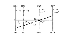
図9は、前記クランク位置調整制御部78によるクランク位置調整制御について説明する共線図であり、前記出力歯車30(リングギヤR1及びR2)に対応する縦線Y4(Y4′)を中央に、前記第1差動機構14における各回転要素に対応する縦線Y1及びY3を紙面向かって右側に、前記第2差動機構16における各回転要素に対応する縦線Y2及びY3′を紙面向かって右側にそれぞれ展開して示している。前記クラッチCLにより前記キャリアC1、C2が係合された状態(回転速度)を一点鎖線X2で示している。この図9に示すように、車両停止時すなわち前記出力歯車30(リングギヤR1、R2)の回転速度が零である状態においては、白抜き矢印で示すように前記出力歯車30(リングギヤR1、R2)に車両慣性乃至パーキングロックの反力がかかる。このような車両停止時であり、且つ、前記クラッチCLが係合されると共に前記ブレーキBKが解放された状態においては、白抜き矢印で示すように前記第1電動機MG1及び第2電動機MG2の何れのトルク(正方向のトルク)によっても、黒矢印で示すように前記エンジン12のクランク回転(クランキング)すなわち前記クランク軸12aの駆動を実現できる。従って、例えば前記第1電動機MG1単独で(第2電動機MG2によりトルクを出力させることなしに)前記クランク軸12aの駆動を行う場合に比べて大きなクランキングトルクを実現することができ、好適に前記クランク位置調整制御を実行することができる。
FIG. 9 is a collinear diagram illustrating crank position adjustment control by the crank position adjustment control unit 78, with the vertical line Y4 (Y4 ′) corresponding to the output gear 30 (ring gears R1 and R2) in the center. Vertical lines Y1 and Y3 corresponding to the rotating elements in the first differential mechanism 14 are on the right side of the drawing, and vertical lines Y2 and Y3 'corresponding to the rotating elements of the second differential mechanism 16 are on the right side of the drawing. Each is shown expanded. A state (rotational speed) in which the carriers C1 and C2 are engaged by the clutch CL is indicated by a one-dot chain line X2. As shown in FIG. 9, when the vehicle is stopped, that is, when the rotational speed of the output gear 30 (ring gears R1, R2) is zero, the output gear 30 (ring gears R1, R2) is indicated by a white arrow. The vehicle inertia or the reaction force of the parking lock is applied to the vehicle. When the vehicle is stopped and the clutch CL is engaged and the brake BK is released, as shown by the white arrow, any of the first electric motor MG1 and the second electric motor MG2 The torque (cranking) of the engine 12, that is, the driving of the crankshaft 12a can be realized by the torque (torque in the positive direction) as shown by the black arrow. Therefore, for example, it is possible to realize a cranking torque that is larger than that in the case where the crankshaft 12a is driven by the first electric motor MG1 alone (without outputting torque by the second electric motor MG2), and preferably Crank position adjustment control can be executed.
前記クランク位置調整制御部78は、好適には、前記エンジン12のクランク位置調整に必要なトルクTcrnkが予め定められた閾値Tgmax未満である場合には、前記クラッチCLを解放させた状態で専ら前記第1電動機MG1により(第2電動機MG2によりトルクを出力させることなしに)前記エンジン12のクランク位置調整を行う。好適には、前記クラッチCL及びブレーキBKを何れも解放させた状態で専ら前記第1電動機MG1により前記エンジン12のクランク位置調整を行う。すなわち、前記クランク駆動トルク判定部80により判定される前記クランク位置調整に必要なトルクTcrnkが予め定められた閾値Tgmax未満である場合には、前記クラッチ係合制御部74により前記クラッチCLを解放させると共に前記ブレーキ係合制御部76により前記ブレーキBKを解放させ、前記電動機作動制御部72により前記インバータ58を介して前記第1電動機MG1の作動(出力トルク)を制御することで、専らその第1電動機MG1により前記エンジン12のクランク位置調整に必要なトルクTcrnkを出力させる。
The crank position adjustment control unit 78 preferably releases the clutch CL when the torque T crnk required for crank position adjustment of the engine 12 is less than a predetermined threshold T gmax. The crank position of the engine 12 is adjusted exclusively by the first electric motor MG1 (without outputting torque by the second electric motor MG2). Preferably, the crank position of the engine 12 is adjusted exclusively by the first electric motor MG1 with both the clutch CL and the brake BK released. That is, when the torque T crnk required for the crank position adjustment determined by the crank drive torque determination unit 80 is less than a predetermined threshold value T gmax , the clutch engagement control unit 74 sets the clutch CL. The brake BK is released by the brake engagement control unit 76 and the operation (output torque) of the first electric motor MG1 is controlled by the electric motor operation control unit 72 via the inverter 58. The first electric motor MG1 outputs a torque T crnk necessary for adjusting the crank position of the engine 12.
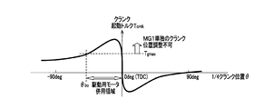
図10は、前記クランク軸12aの調整前における回転角度位置(1/4クランク位置)PCRと、そのクランク軸12aのクランク位置調整に必要なトルク(クランク起動トルク)Tcrnkとの関係の一例を示す図である。この図10に示す例では、前記クランク軸12aの調整前における回転角度位置がθbo~0(deg)の角度範囲において、クランク位置調整に必要なトルクTcrnkが、前記第1電動機MG1単独でクランク位置調整を行い得る上限値である前記閾値Tgmax以上となっている。換言すれば、このθbo~0(deg)の角度範囲内では、前記第1電動機MG1単独ではクランク位置調整を行うことができないため、前記第1電動機MG1及び第2電動機MG2により協働してクランク位置調整を行う必要がある。一方、前記θbo~0(deg)の角度範囲外では、前記第1電動機MG1単独でクランク位置調整を行うことができる。
Figure 10 shows an example of a rotation angle position (1/4 crank position) and P CR, the relationship between the crank shaft 12a required torque to the crank position adjustment (crank starting torque) T Crnk before adjustment of the crank shaft 12a FIG. In the example shown in FIG. 10, the torque T crnk required for crank position adjustment is obtained by the first electric motor MG1 alone when the rotation angle position before adjustment of the crankshaft 12a is in an angle range of θ bo to 0 (deg). It is equal to or greater than the threshold value Tgmax, which is the upper limit value at which the crank position can be adjusted. In other words, within the angle range of θ bo to 0 (deg), the first electric motor MG1 alone cannot adjust the crank position, so the first electric motor MG1 and the second electric motor MG2 cooperate. It is necessary to adjust the crank position. On the other hand, outside the angle range of θ bo to 0 (deg), the crank position can be adjusted by the first electric motor MG1 alone.
前記クランク位置調整制御部78は、好適には、駆動用バッテリである前記バッテリ55の許容出力WOUTが予め定められた閾値未満である場合には、前記クラッチCLを解放させ、前記第2電動機MG2による前記エンジン12のクランク位置調整を禁止する。更に好適には、前記バッテリ55の許容出力WOUTが予め定められた閾値未満である場合には、前記クランク位置調整制御部78によるクランク位置調整制御を禁止する(非実行とする)。前記閾値は、好適には、前記クランク駆動トルク判定部80により判定される、前記クランク軸12aの位置調整に必要なトルクTcrnkを出力させるために、前記バッテリ55から出力されるエネルギであるクランク駆動パワーPcrnkである。すなわち、好適には、駆動用バッテリである前記バッテリ55の許容出力WOUTが、前記クランク駆動トルク判定部80により判定されるクランク駆動パワーPcrnk未満である場合には、前記クランク位置調整制御部78によるクランク位置調整制御を禁止する。
The crank position adjustment control unit 78 preferably releases the clutch CL when the allowable output W OUT of the battery 55, which is a drive battery, is less than a predetermined threshold value, and the second electric motor. The crank position adjustment of the engine 12 by MG2 is prohibited. More preferably, when the allowable output W OUT of the battery 55 is less than a predetermined threshold, the crank position adjustment control by the crank position adjustment control unit 78 is prohibited (not executed). Preferably, the threshold is a crank that is energy output from the battery 55 in order to output the torque T crnk required for adjusting the position of the crankshaft 12a, which is determined by the crank driving torque determination unit 80. Drive power P crnk . That is, preferably, when the allowable output W OUT of the battery 55 that is a drive battery is less than the crank drive power P crnk determined by the crank drive torque determination unit 80, the crank position adjustment control unit The crank position adjustment control by 78 is prohibited.
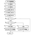
図11は、前記電子制御装置40によるクランク位置調整制御の一例の要部を説明するフローチャートであり、所定の周期で繰り返し実行されるものである。
FIG. 11 is a flowchart for explaining a main part of an example of the crank position adjustment control by the electronic control unit 40, which is repeatedly executed at a predetermined cycle.
先ず、ステップ(以下、ステップを省略する)S1において、前記クランク位置センサ52の検出結果に基づいて前記エンジン12のクランク軸12aの回転角度位置PCRが判定される。次に、S2において、前記エンジン温度センサ53の検出結果に基づいて前記エンジン12の温度ThEが判定される。次に、S3において、S1にて検出された前記クランク軸12aの回転角度位置PCR及びS2にて検出された前記エンジン温度ThE等に基づいて、クランク起動トルクすなわち前記エンジン12のクランク位置調整に必要なトルクTcrnkが推定(判定)される。次に、S4において、S3にて推定されたトルクTcrnkを出力させるために、前記バッテリ55から出力される(持ち出される)エネルギであるクランク駆動パワーPcrnkが推定(判定)される。次に、S5において、前記バッテリSOCセンサ54の検出結果に基づいて前記バッテリ55の許容出力(出力許容値)WOUTが判定される。次に、S6において、S5にて判定された前記バッテリ55の許容出力WOUTが、S4にて推定されたクランク駆動パワーPcrnkよりも大きいか否かが判断される。このS6の判断が否定される場合には、クランク位置調整制御が行われることなく、それをもって本ルーチンが終了させられるが、S6の判断が肯定される場合には、S7において、S3にて推定されたクランク起動トルクTcrnkが、予め定められた閾値Tgmaxよりも大きいか否かが判断される。このS7の判断が肯定される場合には、S8において、前記クラッチCLが係合されると共に前記ブレーキBKが解放され、S9において、前記第1電動機MG1及び第2電動機MG2により協働して前記クランク軸12aの位置調整制御が実行された後、本ルーチンが終了させられるが、S7の判断が否定される場合には、S10において、前記クラッチCLが解放されると共に好適には前記ブレーキBKが解放され、S11において、専ら前記第1電動機MG1により前記クランク軸12aの位置調整制御が実行された後、本ルーチンが終了させられる。
First, step (hereinafter abbreviated step) in S1, the rotational angular position P CR of the crank shaft 12a of the engine 12 based on a detection result of the crank position sensor 52 is determined. Next, in S2, the temperature Th E of the engine 12 is determined based on the detection result of the engine temperature sensor 53. Next, at S3, based on the detected engine temperature Th E etc. at the rotational angular position P CR and S2 detected the crankshaft 12a at S1, the crank starting torque i.e. the crank position adjustment of the engine 12 Is estimated (determined). Next, in S4, in order to output the torque T crnk estimated in S3, the crank drive power P crnk that is energy output (taken out) from the battery 55 is estimated (determined). Next, in S5, the allowable output (output allowable value) W OUT of the battery 55 is determined based on the detection result of the battery SOC sensor 54. Next, in S6, it is determined whether or not the allowable output W OUT of the battery 55 determined in S5 is larger than the crank driving power P crnk estimated in S4. If the determination in S6 is negative, the crank position adjustment control is not performed, and the routine is terminated. However, if the determination in S6 is affirmative, in S7, the estimation is performed in S3. It is determined whether or not the crank start torque T crnk is greater than a predetermined threshold T gmax . If the determination in S7 is affirmative, in S8, the clutch CL is engaged and the brake BK is released, and in S9, the first motor MG1 and the second motor MG2 cooperate with each other. After the position adjustment control of the crankshaft 12a is executed, this routine is terminated. If the determination in S7 is negative, in S10, the clutch CL is released and the brake BK is preferably operated. In step S11, after the position adjustment control of the crankshaft 12a is executed exclusively by the first electric motor MG1, this routine is terminated.
以上の制御において、S9及びS11が前記電動機作動制御部72の動作に、S8及びS10が前記クラッチ係合制御部74及びブレーキ係合制御部76の動作に、S1~S11が前記クランク位置調整制御部78の動作に、S3、S4、及びS7が前記クランク駆動トルク判定部80の動作に、S5及びS6が前記バッテリ許容出力判定部82の動作に、それぞれ対応する。
In the above control, S9 and S11 are the operations of the motor operation control unit 72, S8 and S10 are the operations of the clutch engagement control unit 74 and the brake engagement control unit 76, and S1 to S11 are the crank position adjustment control. S3, S4, and S7 correspond to the operation of the crank drive torque determination unit 80, and S5 and S6 correspond to the operation of the battery allowable output determination unit 82, respectively.
続いて、本発明の他の好適な実施例を図面に基づいて詳細に説明する。以下の説明において、実施例相互に共通する部分については同一の符号を付してその説明を省略する。
Subsequently, another preferred embodiment of the present invention will be described in detail with reference to the drawings. In the following description, parts common to the embodiments are denoted by the same reference numerals and description thereof is omitted.
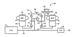
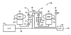
図18~図20は、前記駆動装置10の代替として、本発明が好適に適用される他のハイブリッド車両用駆動装置160、170、180の構成及び作動をそれぞれ説明する共線図である。図18~図20では、前述した図4~7等の共線図と同様に、前記第1遊星歯車装置14におけるサンギヤS1、キャリアC1、リングギヤR1の相対的な回転速度を実線L1で、前記第2遊星歯車装置16におけるサンギヤS2、キャリアC2、リングギヤR2の相対的な回転速度を破線L2でそれぞれ示している。図18に示すハイブリッド車両用駆動装置160では、前記第1遊星歯車装置14のサンギヤS1、キャリアC1、及びリングギヤR1は、前記第1電動機MG1、前記エンジン12、及び前記第2電動機MG2にそれぞれ連結されている。前記第2遊星歯車装置16のサンギヤS2、キャリアC2、及びリングギヤR2は、前記第2電動機MG2、前記出力歯車30、及び前記ブレーキBKを介して前記ハウジング26にそれぞれ連結されている。前記サンギヤS1とリングギヤR2とが前記クラッチCLを介して選択的に連結されている。前記リングギヤR1とサンギヤS2とが相互に連結されている。図19に示すハイブリッド車両用駆動装置170では、前記第1遊星歯車装置14のサンギヤS1、キャリアC1、及びリングギヤR1は、前記第1電動機MG1、前記出力歯車30、及び前記エンジン12にそれぞれ連結されている。前記第2遊星歯車装置16のサンギヤS2、キャリアC2、及びリングギヤR2は、前記第2電動機MG2、前記出力歯車30、及び前記ブレーキBKを介して前記ハウジング26にそれぞれ連結されている。前記サンギヤS1と前記リングギヤR2とが前記クラッチCLを介して選択的に連結されている。前記クラッチC1及びC2が相互に連結されている。図20に示すハイブリッド車両用駆動装置180では、前記第1遊星歯車装置14のサンギヤS1、キャリアC1、及びリングギヤR1は、前記第1電動機MG1、前記出力歯車30、及び前記エンジン12にそれぞれ連結されている。前記第2遊星歯車装置16のサンギヤS2、キャリアC2、及びリングギヤR2は、前記第2電動機MG2、前記ブレーキBKを介して前記ハウジング26、及び前記出力歯車30にそれぞれ連結されている。前記リングギヤR1とキャリアC2とがクラッチCLを介して選択的に連結されている。前記キャリアC1とリングギヤR2とが相互に連結されている。
18 to 20 are collinear diagrams illustrating the configuration and operation of other hybrid vehicle drive devices 160, 170, and 180 to which the present invention is preferably applied as an alternative to the drive device 10. FIG. 18 to 20, the relative rotational speeds of the sun gear S1, the carrier C1, and the ring gear R1 in the first planetary gear device 14 are indicated by the solid line L1 as in the collinear charts of FIGS. The relative rotational speeds of the sun gear S2, the carrier C2, and the ring gear R2 in the second planetary gear device 16 are indicated by broken lines L2. In the hybrid vehicle drive device 160 shown in FIG. 18, the sun gear S1, the carrier C1, and the ring gear R1 of the first planetary gear device 14 are connected to the first electric motor MG1, the engine 12, and the second electric motor MG2, respectively. Has been. The sun gear S2, the carrier C2, and the ring gear R2 of the second planetary gear device 16 are connected to the housing 26 via the second electric motor MG2, the output gear 30, and the brake BK, respectively. The sun gear S1 and the ring gear R2 are selectively connected via the clutch CL. The ring gear R1 and the sun gear S2 are connected to each other. In the hybrid vehicle drive device 170 shown in FIG. 19, the sun gear S1, the carrier C1, and the ring gear R1 of the first planetary gear device 14 are connected to the first electric motor MG1, the output gear 30, and the engine 12, respectively. ing. The sun gear S2, the carrier C2, and the ring gear R2 of the second planetary gear device 16 are connected to the housing 26 via the second electric motor MG2, the output gear 30, and the brake BK, respectively. The sun gear S1 and the ring gear R2 are selectively connected via the clutch CL. The clutches C1 and C2 are connected to each other. In the hybrid vehicle drive device 180 shown in FIG. 20, the sun gear S1, the carrier C1, and the ring gear R1 of the first planetary gear device 14 are connected to the first electric motor MG1, the output gear 30, and the engine 12, respectively. ing. The sun gear S2, the carrier C2, and the ring gear R2 of the second planetary gear device 16 are connected to the housing 26 and the output gear 30 through the second electric motor MG2 and the brake BK, respectively. The ring gear R1 and the carrier C2 are selectively connected via a clutch CL. The carrier C1 and the ring gear R2 are connected to each other.
図8等を用いて前述した本発明のハイブリッド車両の駆動制御装置は、図18~図20に示す構成にも好適に適用される。すなわち、車両の状態に応じて前記第1電動機MG1及び第2電動機MG2の少なくとも一方により前記エンジン12のクランク位置調整が行われる。好適には、前記エンジン12のクランク位置調整に必要なトルクTcrnkが予め定められた閾値以上である場合には、前記クラッチCLを係合させると共に前記ブレーキBKを解放させた状態で前記第1電動機MG1及び第2電動機MG2により前記エンジン12のクランク位置調整を行うが、前記エンジン12のクランク位置調整に必要なトルクTcrnkが前記閾値未満である場合には、前記クラッチCLを解放させた状態で前記第1電動機MG1により前記エンジン12のクランク位置調整を行う等の制御が行われる。斯かる制御により、前記駆動装置160、170、180等によっても、エンジン始動に際してクランク位置を調整して始動ショック等の不具合の発生を抑制するという効果が得られる。
The drive control apparatus for a hybrid vehicle of the present invention described above with reference to FIG. 8 and the like is also preferably applied to the configurations shown in FIGS. That is, the crank position of the engine 12 is adjusted by at least one of the first electric motor MG1 and the second electric motor MG2 according to the state of the vehicle. Preferably, when the torque T crnk required for adjusting the crank position of the engine 12 is equal to or greater than a predetermined threshold value, the first clutch is engaged with the clutch CL engaged and the brake BK released. The crank position of the engine 12 is adjusted by the electric motor MG1 and the second electric motor MG2. When the torque T crnk necessary for adjusting the crank position of the engine 12 is less than the threshold value, the clutch CL is released. Thus, control such as adjusting the crank position of the engine 12 is performed by the first electric motor MG1. By such control, the driving devices 160, 170, 180, etc. can also achieve the effect of adjusting the crank position when starting the engine and suppressing the occurrence of problems such as a start shock.
図12~図20に示す実施例では、前述した図4~7等に示す実施例と同様に、共線図上において4つの回転要素を有する(4つの回転要素として表現される)第1差動機構である第1遊星歯車装置14及び第2差動機構としての第2遊星歯車装置16、16′と、それら4つの回転要素にそれぞれ連結された第1電動機MG1、第2電動機MG2、エンジン12、及び出力回転部材(出力歯車30)とを、備え、前記4つの回転要素のうちの1つは、前記第1遊星歯車装置14の回転要素と前記第2遊星歯車装置16、16′の回転要素とがクラッチCLを介して選択的に連結され、そのクラッチCLによる係合対象となる前記第2遊星歯車装置16、16′の回転要素が、非回転部材であるハウジング26に対してブレーキBKを介して選択的に連結されるハイブリッド車両の駆動制御装置である点で、共通している。
In the embodiment shown in FIGS. 12 to 20, the first difference having four rotation elements (expressed as four rotation elements) on the collinear chart is the same as the embodiment shown in FIGS. The first planetary gear unit 14 as a moving mechanism and the second planetary gear units 16 and 16 'as a second differential mechanism, and a first electric motor MG1, a second electric motor MG2, and an engine connected to the four rotating elements, respectively. 12 and an output rotation member (output gear 30), one of the four rotation elements being the rotation element of the first planetary gear device 14 and the second planetary gear device 16, 16 '. A rotating element is selectively connected via a clutch CL, and the rotating element of the second planetary gear devices 16 and 16 'to be engaged by the clutch CL is braked against the housing 26 which is a non-rotating member. Via BK In that it is a drive control apparatus for a hybrid vehicle which is selectively connected, it is common.
このように、本実施例によれば、クラッチCLが係合された状態において全体として4つの回転要素を有する(図4~図7等に示す共線図上において4つの回転要素として表される)第1差動機構である第1遊星歯車装置14及び第2差動機構である第2遊星歯車装置16、16′と、それら4つの回転要素にそれぞれ連結されたエンジン12、第1電動機MG1、第2電動機MG2、及び出力回転部材である出力歯車30とを、備え、前記4つの回転要素のうちの1つは、前記第1差動機構の回転要素と前記第2差動機構の回転要素とがクラッチCLを介して選択的に連結され、そのクラッチCLによる係合対象となる前記第1差動機構又は前記第2差動機構の回転要素が、非回転部材であるハウジング26に対してブレーキBKを介して選択的に連結されるハイブリッド車両の駆動制御装置であって、車両の状態に応じて前記第1電動機MG1及び第2電動機MG2の少なくとも一方により前記エンジン12のクランク位置調整を行うものであることから、例えばクランキングに比較的大きなトルクが必要とされる場合には前記第1電動機MG1及び第2電動機MG2を併用することにより、好適に前記エンジン12のクランク位置調整を行うことができる。すなわち、エンジン始動に際してクランク位置を調整して始動ショック等の不具合の発生を抑制するハイブリッド車両の駆動制御装置としての前記電子制御装置40を提供することができる。
As described above, according to the present embodiment, there are four rotating elements as a whole in a state in which the clutch CL is engaged (represented as four rotating elements on the collinear chart shown in FIGS. 4 to 7 and the like). ) The first planetary gear unit 14 that is the first differential mechanism and the second planetary gear units 16 and 16 'that are the second differential mechanism, and the engine 12 and the first electric motor MG1 that are respectively connected to these four rotating elements. , A second electric motor MG2, and an output gear 30 that is an output rotation member, and one of the four rotation elements is a rotation element of the first differential mechanism and a rotation of the second differential mechanism. Are connected to each other through a clutch CL, and the rotating element of the first differential mechanism or the second differential mechanism to be engaged by the clutch CL is connected to the housing 26 which is a non-rotating member. Through the brake BK A drive control device for a hybrid vehicle that is selectively connected, wherein the crank position of the engine 12 is adjusted by at least one of the first electric motor MG1 and the second electric motor MG2 in accordance with the state of the vehicle. For example, when a relatively large torque is required for cranking, the crank position of the engine 12 can be adjusted suitably by using the first electric motor MG1 and the second electric motor MG2 together. That is, the electronic control device 40 can be provided as a drive control device for a hybrid vehicle that adjusts the crank position when starting the engine and suppresses the occurrence of problems such as a start shock.
前記エンジン12のクランク位置調整に必要なトルクTcrnkが予め定められた閾値Tgmax以上である場合には、前記クラッチCLを係合させると共に前記ブレーキBKを解放させた状態で前記第1電動機MG1及び第2電動機MG2により前記エンジン12のクランク位置調整を行うが、前記エンジン12のクランク位置調整に必要なトルクTcrnkが前記閾値Tgmax未満である場合には、前記クラッチCLを解放させた状態で前記第1電動機MG1により前記エンジン12のクランク位置調整を行うものであるため、クランク軸12aの駆動トルクが比較的大きい場合には、前記第1電動機MG1及び第2電動機MG2を併用することにより好適に前記エンジン12のクランク位置調整を行うことができる一方、クランク軸12aの駆動トルクが比較的小さい場合には、専ら前記第1電動機MG1によりクランク位置調整を行うことで不要な油圧制御及び無駄な電力消費を行うことなく好適にクランク位置調整を実現することができる。
When the torque T crnk necessary for adjusting the crank position of the engine 12 is equal to or greater than a predetermined threshold value T gmax , the first electric motor MG1 is engaged with the clutch CL engaged and the brake BK released. state and the performs the crank position adjustment of the engine 12 by the second electric motor MG2, when the torque T Crnk necessary crank position adjustment of the engine 12 is less than the threshold value T gmax is obtained by releasing the clutch CL Since the crank position of the engine 12 is adjusted by the first electric motor MG1, when the driving torque of the crankshaft 12a is relatively large, the first electric motor MG1 and the second electric motor MG2 are used together. While the crank position of the engine 12 can be adjusted suitably, the driving torque of the crankshaft 12a Relatively smaller can solely realize the suitably crank position adjustment without unnecessary hydraulic control and wasteful power consumption by performing the crank position adjusted by the first electric motor MG1.
駆動用バッテリである前記バッテリ55の許容出力WOUTが予め定められた閾値未満である場合には、前記エンジン12のクランク位置調整を禁止するものであるため、許容出力WOUTが不十分であるにもかかわらず前記クランク位置調整のために電力を消費してしまい、結果、前記エンジン12の始動に必要な電力が不足するのを好適に抑制することができる。
When the allowable output W OUT of the battery 55 that is a driving battery is less than a predetermined threshold value, the allowable output W OUT is insufficient because the crank position adjustment of the engine 12 is prohibited. Nevertheless, electric power is consumed for adjusting the crank position, and as a result, it is possible to suitably suppress a shortage of electric power necessary for starting the engine 12.
前記第1遊星歯車装置14は、前記第1電動機MG1に連結された第1回転要素としてのサンギヤS1、前記エンジン12に連結された第2回転要素としてのキャリアC1、及び前記出力歯車30に連結された第3回転要素としてのリングギヤR1を備え、前記第2遊星歯車装置16(16′)は、前記第2電動機MG2に連結された第1回転要素としてのサンギヤS2(S2′)、第2回転要素としてのキャリアC2(C2′)、及び第3回転要素としてのリングギヤR2(R2′)を備え、それらキャリアC2(C2′)及びリングギヤR2(R2′)の何れか一方が前記第1遊星歯車装置14のリングギヤR1に連結されたものであり、前記クラッチCLは、前記第1遊星歯車装置14におけるキャリアC1と、前記キャリアC2(C2′)及びリングギヤR2(R2′)のうち前記リングギヤR1に連結されていない方の回転要素とを選択的に係合させるものであり、前記ブレーキBKは、前記キャリアC2(C2′)及びリングギヤR2(R2′)のうち前記リングギヤR1に連結されていない方の回転要素を、非回転部材であるハウジング26に対して選択的に係合させるものであることから、実用的なハイブリッド車両の駆動装置10等において、エンジン始動に際してクランク位置を調整して始動ショック等の不具合の発生を抑制することができる。
The first planetary gear unit 14 is connected to a sun gear S1 as a first rotating element connected to the first electric motor MG1, a carrier C1 as a second rotating element connected to the engine 12, and the output gear 30. The second planetary gear unit 16 (16 ′) includes a sun gear S2 (S2 ′), a second rotation element connected to the second electric motor MG2, and a second gear R1. A carrier C2 (C2 ′) as a rotating element and a ring gear R2 (R2 ′) as a third rotating element are provided, and any one of the carrier C2 (C2 ′) and the ring gear R2 (R2 ′) is the first planet. The clutch CL is connected to the ring gear R1 of the gear device 14, and the clutch CL includes the carrier C1 in the first planetary gear device 14 and the carrier C2 ( 2 ′) and the ring gear R2 (R2 ′), which is selectively engaged with the rotating element not connected to the ring gear R1, the brake BK includes the carrier C2 (C2 ′) and the ring gear. R2 (R2 ′), which is not connected to the ring gear R1, is selectively engaged with the housing 26, which is a non-rotating member. In the apparatus 10 or the like, the crank position can be adjusted when starting the engine to suppress the occurrence of problems such as a start shock.
以上、本発明の好適な実施例を図面に基づいて詳細に説明したが、本発明はこれに限定されるものではなく、その趣旨を逸脱しない範囲内において種々の変更が加えられて実施されるものである。
The preferred embodiments of the present invention have been described in detail with reference to the drawings. However, the present invention is not limited to these embodiments, and various modifications can be made without departing from the spirit of the present invention. Is.