WO2013145090A1 - Drive control device for hybrid vehicle - Google Patents

Drive control device for hybrid vehicle Download PDF

Info

Publication number
WO2013145090A1
WO2013145090A1 PCT/JP2012/057809 JP2012057809W WO2013145090A1 WO 2013145090 A1 WO2013145090 A1 WO 2013145090A1 JP 2012057809 W JP2012057809 W JP 2012057809W WO 2013145090 A1 WO2013145090 A1 WO 2013145090A1
Authority
WO
WIPO (PCT)
Prior art keywords
engine
electric motor
clutch
rotating element
planetary gear
Prior art date
Application number
PCT/JP2012/057809
Other languages
French (fr)
Japanese (ja)
Inventor
広康 原田
正人 寺島
宏司 林
智仁 大野
石井 啓之
Original Assignee
トヨタ自動車株式会社
Priority date (The priority date is an assumption and is not a legal conclusion. Google has not performed a legal analysis and makes no representation as to the accuracy of the date listed.)
Filing date
Publication date
Application filed by トヨタ自動車株式会社 filed Critical トヨタ自動車株式会社
Priority to US14/387,765 priority Critical patent/US20150087458A1/en
Priority to CN201280071865.6A priority patent/CN104220314A/en
Priority to PCT/JP2012/057809 priority patent/WO2013145090A1/en
Priority to EP12872877.1A priority patent/EP2832614A1/en
Publication of WO2013145090A1 publication Critical patent/WO2013145090A1/en

Links

Images

Classifications

    • BPERFORMING OPERATIONS; TRANSPORTING
    • B60VEHICLES IN GENERAL
    • B60WCONJOINT CONTROL OF VEHICLE SUB-UNITS OF DIFFERENT TYPE OR DIFFERENT FUNCTION; CONTROL SYSTEMS SPECIALLY ADAPTED FOR HYBRID VEHICLES; ROAD VEHICLE DRIVE CONTROL SYSTEMS FOR PURPOSES NOT RELATED TO THE CONTROL OF A PARTICULAR SUB-UNIT
    • B60W10/00Conjoint control of vehicle sub-units of different type or different function
    • B60W10/10Conjoint control of vehicle sub-units of different type or different function including control of change-speed gearings
    • BPERFORMING OPERATIONS; TRANSPORTING
    • B60VEHICLES IN GENERAL
    • B60WCONJOINT CONTROL OF VEHICLE SUB-UNITS OF DIFFERENT TYPE OR DIFFERENT FUNCTION; CONTROL SYSTEMS SPECIALLY ADAPTED FOR HYBRID VEHICLES; ROAD VEHICLE DRIVE CONTROL SYSTEMS FOR PURPOSES NOT RELATED TO THE CONTROL OF A PARTICULAR SUB-UNIT
    • B60W10/00Conjoint control of vehicle sub-units of different type or different function
    • B60W10/02Conjoint control of vehicle sub-units of different type or different function including control of driveline clutches
    • BPERFORMING OPERATIONS; TRANSPORTING
    • B60VEHICLES IN GENERAL
    • B60KARRANGEMENT OR MOUNTING OF PROPULSION UNITS OR OF TRANSMISSIONS IN VEHICLES; ARRANGEMENT OR MOUNTING OF PLURAL DIVERSE PRIME-MOVERS IN VEHICLES; AUXILIARY DRIVES FOR VEHICLES; INSTRUMENTATION OR DASHBOARDS FOR VEHICLES; ARRANGEMENTS IN CONNECTION WITH COOLING, AIR INTAKE, GAS EXHAUST OR FUEL SUPPLY OF PROPULSION UNITS IN VEHICLES
    • B60K6/00Arrangement or mounting of plural diverse prime-movers for mutual or common propulsion, e.g. hybrid propulsion systems comprising electric motors and internal combustion engines ; Control systems therefor, i.e. systems controlling two or more prime movers, or controlling one of these prime movers and any of the transmission, drive or drive units Informative references: mechanical gearings with secondary electric drive F16H3/72; arrangements for handling mechanical energy structurally associated with the dynamo-electric machine H02K7/00; machines comprising structurally interrelated motor and generator parts H02K51/00; dynamo-electric machines not otherwise provided for in H02K see H02K99/00
    • B60K6/20Arrangement or mounting of plural diverse prime-movers for mutual or common propulsion, e.g. hybrid propulsion systems comprising electric motors and internal combustion engines ; Control systems therefor, i.e. systems controlling two or more prime movers, or controlling one of these prime movers and any of the transmission, drive or drive units Informative references: mechanical gearings with secondary electric drive F16H3/72; arrangements for handling mechanical energy structurally associated with the dynamo-electric machine H02K7/00; machines comprising structurally interrelated motor and generator parts H02K51/00; dynamo-electric machines not otherwise provided for in H02K see H02K99/00 the prime-movers consisting of electric motors and internal combustion engines, e.g. HEVs
    • B60K6/22Arrangement or mounting of plural diverse prime-movers for mutual or common propulsion, e.g. hybrid propulsion systems comprising electric motors and internal combustion engines ; Control systems therefor, i.e. systems controlling two or more prime movers, or controlling one of these prime movers and any of the transmission, drive or drive units Informative references: mechanical gearings with secondary electric drive F16H3/72; arrangements for handling mechanical energy structurally associated with the dynamo-electric machine H02K7/00; machines comprising structurally interrelated motor and generator parts H02K51/00; dynamo-electric machines not otherwise provided for in H02K see H02K99/00 the prime-movers consisting of electric motors and internal combustion engines, e.g. HEVs characterised by apparatus, components or means specially adapted for HEVs
    • B60K6/36Arrangement or mounting of plural diverse prime-movers for mutual or common propulsion, e.g. hybrid propulsion systems comprising electric motors and internal combustion engines ; Control systems therefor, i.e. systems controlling two or more prime movers, or controlling one of these prime movers and any of the transmission, drive or drive units Informative references: mechanical gearings with secondary electric drive F16H3/72; arrangements for handling mechanical energy structurally associated with the dynamo-electric machine H02K7/00; machines comprising structurally interrelated motor and generator parts H02K51/00; dynamo-electric machines not otherwise provided for in H02K see H02K99/00 the prime-movers consisting of electric motors and internal combustion engines, e.g. HEVs characterised by apparatus, components or means specially adapted for HEVs characterised by the transmission gearings
    • B60K6/365Arrangement or mounting of plural diverse prime-movers for mutual or common propulsion, e.g. hybrid propulsion systems comprising electric motors and internal combustion engines ; Control systems therefor, i.e. systems controlling two or more prime movers, or controlling one of these prime movers and any of the transmission, drive or drive units Informative references: mechanical gearings with secondary electric drive F16H3/72; arrangements for handling mechanical energy structurally associated with the dynamo-electric machine H02K7/00; machines comprising structurally interrelated motor and generator parts H02K51/00; dynamo-electric machines not otherwise provided for in H02K see H02K99/00 the prime-movers consisting of electric motors and internal combustion engines, e.g. HEVs characterised by apparatus, components or means specially adapted for HEVs characterised by the transmission gearings with the gears having orbital motion
    • BPERFORMING OPERATIONS; TRANSPORTING
    • B60VEHICLES IN GENERAL
    • B60KARRANGEMENT OR MOUNTING OF PROPULSION UNITS OR OF TRANSMISSIONS IN VEHICLES; ARRANGEMENT OR MOUNTING OF PLURAL DIVERSE PRIME-MOVERS IN VEHICLES; AUXILIARY DRIVES FOR VEHICLES; INSTRUMENTATION OR DASHBOARDS FOR VEHICLES; ARRANGEMENTS IN CONNECTION WITH COOLING, AIR INTAKE, GAS EXHAUST OR FUEL SUPPLY OF PROPULSION UNITS IN VEHICLES
    • B60K6/00Arrangement or mounting of plural diverse prime-movers for mutual or common propulsion, e.g. hybrid propulsion systems comprising electric motors and internal combustion engines ; Control systems therefor, i.e. systems controlling two or more prime movers, or controlling one of these prime movers and any of the transmission, drive or drive units Informative references: mechanical gearings with secondary electric drive F16H3/72; arrangements for handling mechanical energy structurally associated with the dynamo-electric machine H02K7/00; machines comprising structurally interrelated motor and generator parts H02K51/00; dynamo-electric machines not otherwise provided for in H02K see H02K99/00
    • B60K6/20Arrangement or mounting of plural diverse prime-movers for mutual or common propulsion, e.g. hybrid propulsion systems comprising electric motors and internal combustion engines ; Control systems therefor, i.e. systems controlling two or more prime movers, or controlling one of these prime movers and any of the transmission, drive or drive units Informative references: mechanical gearings with secondary electric drive F16H3/72; arrangements for handling mechanical energy structurally associated with the dynamo-electric machine H02K7/00; machines comprising structurally interrelated motor and generator parts H02K51/00; dynamo-electric machines not otherwise provided for in H02K see H02K99/00 the prime-movers consisting of electric motors and internal combustion engines, e.g. HEVs
    • B60K6/42Arrangement or mounting of plural diverse prime-movers for mutual or common propulsion, e.g. hybrid propulsion systems comprising electric motors and internal combustion engines ; Control systems therefor, i.e. systems controlling two or more prime movers, or controlling one of these prime movers and any of the transmission, drive or drive units Informative references: mechanical gearings with secondary electric drive F16H3/72; arrangements for handling mechanical energy structurally associated with the dynamo-electric machine H02K7/00; machines comprising structurally interrelated motor and generator parts H02K51/00; dynamo-electric machines not otherwise provided for in H02K see H02K99/00 the prime-movers consisting of electric motors and internal combustion engines, e.g. HEVs characterised by the architecture of the hybrid electric vehicle
    • B60K6/44Series-parallel type
    • B60K6/445Differential gearing distribution type
    • BPERFORMING OPERATIONS; TRANSPORTING
    • B60VEHICLES IN GENERAL
    • B60WCONJOINT CONTROL OF VEHICLE SUB-UNITS OF DIFFERENT TYPE OR DIFFERENT FUNCTION; CONTROL SYSTEMS SPECIALLY ADAPTED FOR HYBRID VEHICLES; ROAD VEHICLE DRIVE CONTROL SYSTEMS FOR PURPOSES NOT RELATED TO THE CONTROL OF A PARTICULAR SUB-UNIT
    • B60W10/00Conjoint control of vehicle sub-units of different type or different function
    • B60W10/04Conjoint control of vehicle sub-units of different type or different function including control of propulsion units
    • B60W10/08Conjoint control of vehicle sub-units of different type or different function including control of propulsion units including control of electric propulsion units, e.g. motors or generators
    • BPERFORMING OPERATIONS; TRANSPORTING
    • B60VEHICLES IN GENERAL
    • B60WCONJOINT CONTROL OF VEHICLE SUB-UNITS OF DIFFERENT TYPE OR DIFFERENT FUNCTION; CONTROL SYSTEMS SPECIALLY ADAPTED FOR HYBRID VEHICLES; ROAD VEHICLE DRIVE CONTROL SYSTEMS FOR PURPOSES NOT RELATED TO THE CONTROL OF A PARTICULAR SUB-UNIT
    • B60W20/00Control systems specially adapted for hybrid vehicles
    • B60W20/20Control strategies involving selection of hybrid configuration, e.g. selection between series or parallel configuration
    • BPERFORMING OPERATIONS; TRANSPORTING
    • B60VEHICLES IN GENERAL
    • B60WCONJOINT CONTROL OF VEHICLE SUB-UNITS OF DIFFERENT TYPE OR DIFFERENT FUNCTION; CONTROL SYSTEMS SPECIALLY ADAPTED FOR HYBRID VEHICLES; ROAD VEHICLE DRIVE CONTROL SYSTEMS FOR PURPOSES NOT RELATED TO THE CONTROL OF A PARTICULAR SUB-UNIT
    • B60W30/00Purposes of road vehicle drive control systems not related to the control of a particular sub-unit, e.g. of systems using conjoint control of vehicle sub-units, or advanced driver assistance systems for ensuring comfort, stability and safety or drive control systems for propelling or retarding the vehicle
    • B60W30/18Propelling the vehicle
    • B60W30/20Reducing vibrations in the driveline
    • BPERFORMING OPERATIONS; TRANSPORTING
    • B60VEHICLES IN GENERAL
    • B60KARRANGEMENT OR MOUNTING OF PROPULSION UNITS OR OF TRANSMISSIONS IN VEHICLES; ARRANGEMENT OR MOUNTING OF PLURAL DIVERSE PRIME-MOVERS IN VEHICLES; AUXILIARY DRIVES FOR VEHICLES; INSTRUMENTATION OR DASHBOARDS FOR VEHICLES; ARRANGEMENTS IN CONNECTION WITH COOLING, AIR INTAKE, GAS EXHAUST OR FUEL SUPPLY OF PROPULSION UNITS IN VEHICLES
    • B60K6/00Arrangement or mounting of plural diverse prime-movers for mutual or common propulsion, e.g. hybrid propulsion systems comprising electric motors and internal combustion engines ; Control systems therefor, i.e. systems controlling two or more prime movers, or controlling one of these prime movers and any of the transmission, drive or drive units Informative references: mechanical gearings with secondary electric drive F16H3/72; arrangements for handling mechanical energy structurally associated with the dynamo-electric machine H02K7/00; machines comprising structurally interrelated motor and generator parts H02K51/00; dynamo-electric machines not otherwise provided for in H02K see H02K99/00
    • B60K6/20Arrangement or mounting of plural diverse prime-movers for mutual or common propulsion, e.g. hybrid propulsion systems comprising electric motors and internal combustion engines ; Control systems therefor, i.e. systems controlling two or more prime movers, or controlling one of these prime movers and any of the transmission, drive or drive units Informative references: mechanical gearings with secondary electric drive F16H3/72; arrangements for handling mechanical energy structurally associated with the dynamo-electric machine H02K7/00; machines comprising structurally interrelated motor and generator parts H02K51/00; dynamo-electric machines not otherwise provided for in H02K see H02K99/00 the prime-movers consisting of electric motors and internal combustion engines, e.g. HEVs
    • B60K6/22Arrangement or mounting of plural diverse prime-movers for mutual or common propulsion, e.g. hybrid propulsion systems comprising electric motors and internal combustion engines ; Control systems therefor, i.e. systems controlling two or more prime movers, or controlling one of these prime movers and any of the transmission, drive or drive units Informative references: mechanical gearings with secondary electric drive F16H3/72; arrangements for handling mechanical energy structurally associated with the dynamo-electric machine H02K7/00; machines comprising structurally interrelated motor and generator parts H02K51/00; dynamo-electric machines not otherwise provided for in H02K see H02K99/00 the prime-movers consisting of electric motors and internal combustion engines, e.g. HEVs characterised by apparatus, components or means specially adapted for HEVs
    • B60K6/38Arrangement or mounting of plural diverse prime-movers for mutual or common propulsion, e.g. hybrid propulsion systems comprising electric motors and internal combustion engines ; Control systems therefor, i.e. systems controlling two or more prime movers, or controlling one of these prime movers and any of the transmission, drive or drive units Informative references: mechanical gearings with secondary electric drive F16H3/72; arrangements for handling mechanical energy structurally associated with the dynamo-electric machine H02K7/00; machines comprising structurally interrelated motor and generator parts H02K51/00; dynamo-electric machines not otherwise provided for in H02K see H02K99/00 the prime-movers consisting of electric motors and internal combustion engines, e.g. HEVs characterised by apparatus, components or means specially adapted for HEVs characterised by the driveline clutches
    • B60K2006/381Arrangement or mounting of plural diverse prime-movers for mutual or common propulsion, e.g. hybrid propulsion systems comprising electric motors and internal combustion engines ; Control systems therefor, i.e. systems controlling two or more prime movers, or controlling one of these prime movers and any of the transmission, drive or drive units Informative references: mechanical gearings with secondary electric drive F16H3/72; arrangements for handling mechanical energy structurally associated with the dynamo-electric machine H02K7/00; machines comprising structurally interrelated motor and generator parts H02K51/00; dynamo-electric machines not otherwise provided for in H02K see H02K99/00 the prime-movers consisting of electric motors and internal combustion engines, e.g. HEVs characterised by apparatus, components or means specially adapted for HEVs characterised by the driveline clutches characterized by driveline brakes
    • BPERFORMING OPERATIONS; TRANSPORTING
    • B60VEHICLES IN GENERAL
    • B60WCONJOINT CONTROL OF VEHICLE SUB-UNITS OF DIFFERENT TYPE OR DIFFERENT FUNCTION; CONTROL SYSTEMS SPECIALLY ADAPTED FOR HYBRID VEHICLES; ROAD VEHICLE DRIVE CONTROL SYSTEMS FOR PURPOSES NOT RELATED TO THE CONTROL OF A PARTICULAR SUB-UNIT
    • B60W2510/00Input parameters relating to a particular sub-units
    • B60W2510/10Change speed gearings
    • B60W2510/1095Inertia
    • BPERFORMING OPERATIONS; TRANSPORTING
    • B60VEHICLES IN GENERAL
    • B60WCONJOINT CONTROL OF VEHICLE SUB-UNITS OF DIFFERENT TYPE OR DIFFERENT FUNCTION; CONTROL SYSTEMS SPECIALLY ADAPTED FOR HYBRID VEHICLES; ROAD VEHICLE DRIVE CONTROL SYSTEMS FOR PURPOSES NOT RELATED TO THE CONTROL OF A PARTICULAR SUB-UNIT
    • B60W2710/00Output or target parameters relating to a particular sub-units
    • B60W2710/02Clutches
    • B60W2710/021Clutch engagement state
    • BPERFORMING OPERATIONS; TRANSPORTING
    • B60VEHICLES IN GENERAL
    • B60WCONJOINT CONTROL OF VEHICLE SUB-UNITS OF DIFFERENT TYPE OR DIFFERENT FUNCTION; CONTROL SYSTEMS SPECIALLY ADAPTED FOR HYBRID VEHICLES; ROAD VEHICLE DRIVE CONTROL SYSTEMS FOR PURPOSES NOT RELATED TO THE CONTROL OF A PARTICULAR SUB-UNIT
    • B60W2710/00Output or target parameters relating to a particular sub-units
    • B60W2710/06Combustion engines, Gas turbines
    • BPERFORMING OPERATIONS; TRANSPORTING
    • B60VEHICLES IN GENERAL
    • B60WCONJOINT CONTROL OF VEHICLE SUB-UNITS OF DIFFERENT TYPE OR DIFFERENT FUNCTION; CONTROL SYSTEMS SPECIALLY ADAPTED FOR HYBRID VEHICLES; ROAD VEHICLE DRIVE CONTROL SYSTEMS FOR PURPOSES NOT RELATED TO THE CONTROL OF A PARTICULAR SUB-UNIT
    • B60W2710/00Output or target parameters relating to a particular sub-units
    • B60W2710/08Electric propulsion units
    • BPERFORMING OPERATIONS; TRANSPORTING
    • B60VEHICLES IN GENERAL
    • B60WCONJOINT CONTROL OF VEHICLE SUB-UNITS OF DIFFERENT TYPE OR DIFFERENT FUNCTION; CONTROL SYSTEMS SPECIALLY ADAPTED FOR HYBRID VEHICLES; ROAD VEHICLE DRIVE CONTROL SYSTEMS FOR PURPOSES NOT RELATED TO THE CONTROL OF A PARTICULAR SUB-UNIT
    • B60W2710/00Output or target parameters relating to a particular sub-units
    • B60W2710/18Braking system
    • YGENERAL TAGGING OF NEW TECHNOLOGICAL DEVELOPMENTS; GENERAL TAGGING OF CROSS-SECTIONAL TECHNOLOGIES SPANNING OVER SEVERAL SECTIONS OF THE IPC; TECHNICAL SUBJECTS COVERED BY FORMER USPC CROSS-REFERENCE ART COLLECTIONS [XRACs] AND DIGESTS
    • Y02TECHNOLOGIES OR APPLICATIONS FOR MITIGATION OR ADAPTATION AGAINST CLIMATE CHANGE
    • Y02TCLIMATE CHANGE MITIGATION TECHNOLOGIES RELATED TO TRANSPORTATION
    • Y02T10/00Road transport of goods or passengers
    • Y02T10/60Other road transportation technologies with climate change mitigation effect
    • Y02T10/62Hybrid vehicles
    • YGENERAL TAGGING OF NEW TECHNOLOGICAL DEVELOPMENTS; GENERAL TAGGING OF CROSS-SECTIONAL TECHNOLOGIES SPANNING OVER SEVERAL SECTIONS OF THE IPC; TECHNICAL SUBJECTS COVERED BY FORMER USPC CROSS-REFERENCE ART COLLECTIONS [XRACs] AND DIGESTS
    • Y10TECHNICAL SUBJECTS COVERED BY FORMER USPC
    • Y10STECHNICAL SUBJECTS COVERED BY FORMER USPC CROSS-REFERENCE ART COLLECTIONS [XRACs] AND DIGESTS
    • Y10S903/00Hybrid electric vehicles, HEVS
    • Y10S903/902Prime movers comprising electrical and internal combustion motors
    • Y10S903/903Prime movers comprising electrical and internal combustion motors having energy storing means, e.g. battery, capacitor
    • Y10S903/946Characterized by control of driveline clutch

Definitions

  • the present invention relates to an improvement of a drive control device for a hybrid vehicle.
  • a hybrid vehicle including at least one electric motor that functions as a drive source is known.
  • this is the vehicle described in Patent Document 1.
  • the brake is provided to fix the output shaft of the internal combustion engine to the non-rotating member, and according to the traveling state of the vehicle. By controlling the engagement state of the brake, it is possible to improve the energy efficiency of the vehicle and to travel according to the driver's request.
  • the present invention has been made against the background of the above circumstances, and an object thereof is to provide a drive control device for a hybrid vehicle that suppresses the generation of noise and vibration.
  • the gist of the first aspect of the present invention is that a first differential mechanism and a second differential mechanism having four rotating elements as a whole, and these four rotating elements are respectively connected.
  • An element is selectively connected via a clutch, and the rotating element of the first differential mechanism or the second differential mechanism to be engaged by the clutch is selected via a brake for a non-rotating member.
  • the hybrid vehicle drive control device is connected to the clutch, and the clutch is engaged when the torque of the second electric motor is within a specified minute range including zero during load operation of the engine.
  • the first differential mechanism and the second differential mechanism having four rotation elements as a whole, the engine, the first electric motor, Two electric motors and an output rotating member, and one of the four rotating elements is selected by selecting the rotating element of the first differential mechanism and the rotating element of the second differential mechanism via a clutch.
  • the rotating element of the first differential mechanism or the second differential mechanism to be engaged by the clutch is selectively connected to the non-rotating member via a brake.
  • the engagement state of the clutch is switched.
  • the second electric If easily resonance of is the drive train around the torque is zero occurs, change the resonance point by changing the inertia balance of the power transmission system, it is possible to suitably suppress the occurrence of resonance. That is, it is possible to provide a drive control device for a hybrid vehicle that suppresses vibration of the power transmission system.
  • the gist of the second invention subordinate to the first invention is that the torque of the second electric motor is within a specified minute range including zero and the occurrence of resonance is detected during load operation of the engine. When predicted, the engagement state of the clutch is switched. In this way, when resonance of the power transmission system is detected or predicted when the second motor torque is near zero, the resonance point is changed by changing the inertia balance of the power transmission system, and the resonance Generation
  • the gist of the third invention subordinate to the first to second inventions is that the first differential mechanism includes a first rotating element connected to the first electric motor and a first rotating element connected to the engine.
  • a second rotating element coupled to the output rotating member, and the second differential mechanism includes a first rotating element coupled to the second electric motor, a second rotating element, And a third rotating element, and either one of the second rotating element or the third rotating element is connected to the third rotating element in the first differential mechanism, and the clutch has the first difference.
  • a second rotating element in the moving mechanism and a rotating element not connected to the third rotating element in the first differential mechanism among the second rotating element and the third rotating element in the second differential mechanism are selected.
  • the brake is Of the second rotating element and the third rotating element in the second differential mechanism, the rotating element that is not connected to the third rotating element in the first differential mechanism is selectively selected with respect to the non-rotating member. To be engaged. If it does in this way, vibration of a power transmission system can be controlled in a practical hybrid vehicle drive device.
  • FIG. 1 is a skeleton diagram illustrating a configuration of a hybrid vehicle drive device to which the present invention is preferably applied. It is a figure explaining the principal part of the control system provided in order to control the drive of the drive device of FIG.
  • FIG. 2 is an engagement table showing clutch and brake engagement states in each of five types of travel modes established in the drive device of FIG. 1.
  • FIG. 4 is a collinear diagram that can represent the relative relationship of the rotational speeds of the respective rotary elements on a straight line in the drive device of FIG. 1, and is a diagram corresponding to modes 1 and 3 of FIG. 3.
  • FIG. 1 is a skeleton diagram illustrating a configuration of a hybrid vehicle drive device to which the present invention is preferably applied. It is a figure explaining the principal part of the control system provided in order to control the drive of the drive device of FIG.
  • FIG. 2 is an engagement table showing clutch and brake engagement states in each of five types of travel modes established in the drive device of FIG. 1.
  • FIG. 4 is a collinear diagram
  • FIG. 4 is a collinear diagram that can represent the relative relationship of the rotation speeds of the respective rotary elements on a straight line in the drive device of FIG. 1, corresponding to mode 2 of FIG. 3.
  • FIG. 4 is a collinear diagram that can represent the relative relationship of the rotational speeds of the respective rotary elements on a straight line in the drive device of FIG. 1, corresponding to mode 4 of FIG. 3.
  • FIG. 4 is a collinear diagram that can represent the relative relationship of the rotational speeds of the respective rotary elements on a straight line in the drive device of FIG. 1, corresponding to mode 5 of FIG. 3. It is a figure explaining the transmission efficiency in the drive device of FIG. It is a functional block diagram explaining the principal part of the control function with which the electronic control apparatus in the drive device of FIG. 1 was equipped.
  • the drive device of FIG. 1 it is a figure which illustrates typically that the resonant frequency of a power transmission system changes according to the engagement state of a clutch. It is a figure explaining the change of the characteristic (resonance frequency) of the power transmission system according to the engagement state of the clutch in the drive device of FIG.
  • the drive device of FIG. 1 it is a figure which illustrates typically that the resonant frequency of a power transmission system changes according to the engagement state of a clutch and a brake. It is a figure explaining the change of the characteristic (resonance frequency) of the power transmission system according to the engagement state of the clutch and brake in the drive device of FIG.
  • FIG. 2 is a diagram illustrating a region where noise due to resonance is generated corresponding to the operating point of the engine in the drive device of FIG. 1, and shows a state where the clutch is released.
  • FIG. 2 is a diagram illustrating a region where noise due to resonance is generated corresponding to the operating point of the engine in the drive device of FIG. 1, and shows a state where a clutch is engaged.
  • It is a flowchart explaining the principal part of the resonance point change control by the electronic controller with which the drive device of FIG. 1 was equipped.
  • 7 is a flowchart for explaining a main part of another resonance point change control by an electronic control device provided in the drive device of FIG. 1. It is a skeleton diagram explaining the composition of the other hybrid vehicle drive device to which the present invention is applied suitably.
  • FIG. 6 is a collinear diagram illustrating the configuration and operation of still another hybrid vehicle drive device to which the present invention is preferably applied.
  • FIG. 6 is a collinear diagram illustrating the configuration and operation of still another hybrid vehicle drive device to which the present invention is preferably applied.
  • FIG. 6 is a collinear diagram illustrating the configuration and operation of still another hybrid vehicle drive device to which the present invention is preferably applied.
  • the first differential mechanism and the second differential mechanism have four rotation elements as a whole when the clutch is engaged.
  • the first differential mechanism and the second differential mechanism are: In the state in which the plurality of clutches are engaged, there are four rotating elements as a whole.
  • the present invention relates to a first differential mechanism and a second differential mechanism that are represented as four rotating elements on the nomographic chart, an engine connected to each of the four rotating elements, a first electric motor, A second electric motor, and an output rotating member, wherein one of the four rotating elements includes a rotating element of the first differential mechanism and a rotating element of the second differential mechanism via a clutch.
  • a hybrid vehicle that is selectively connected and a rotating element of the first differential mechanism or the second differential mechanism that is to be engaged by the clutch is selectively connected to a non-rotating member via a brake. It is suitably applied to the drive control apparatus.
  • the clutch and the brake are preferably hydraulic engagement devices whose engagement state is controlled (engaged or released) according to the hydraulic pressure, for example, a wet multi-plate friction engagement device.
  • a meshing engagement device that is, a so-called dog clutch (meshing clutch) may be used.
  • the engagement state may be controlled (engaged or released) according to an electrical command, such as an electromagnetic clutch or a magnetic powder clutch.
  • one of a plurality of travel modes is selectively established according to the engagement state of the clutch and the brake.
  • the operation of the engine is stopped and the brake is engaged and the clutch is released in an EV traveling mode in which at least one of the first electric motor and the second electric motor is used as a driving source for traveling.
  • mode 1 is established
  • mode 2 is established by engaging both the brake and the clutch.
  • the mode is set when the brake is engaged and the clutch is released.
  • Mode 4 is established when the brake is released and the clutch is engaged
  • mode 5 is established when both the brake and the clutch are released.
  • each rotating element in each of the first differential mechanism and the second differential mechanism when the clutch is engaged and the brake is released.
  • the arrangement order indicates the first rotation in the first differential mechanism when the rotation speeds corresponding to the second rotation element and the third rotation element in each of the first differential mechanism and the second differential mechanism are superimposed.
  • control for engaging the clutch is performed. That is, control is performed to engage the clutch even when the currently determined travel mode is a travel mode established by releasing the clutch. More preferably, when the torque of the second electric motor is within a specified minute range including zero and the occurrence of resonance is detected or predicted during load operation of the engine, the clutch is engaged. Take control.
  • the temperature of the power transmission system is equal to or lower than a predetermined threshold value, it is determined that the occurrence of resonance in the power transmission system is detected or predicted.
  • a predetermined threshold value it is determined that the occurrence of resonance in the power transmission system is detected or predicted.
  • an EGR that circulates a part of the exhaust gas of the engine into the intake gas it is determined that the occurrence of resonance in the power transmission system is detected or predicted.
  • the engine is being driven to warm up the catalytic converter, it is determined that the occurrence of resonance in the power transmission system is detected or predicted.
  • FIG. 1 is a skeleton diagram illustrating the configuration of a hybrid vehicle drive device 10 (hereinafter simply referred to as drive device 10) to which the present invention is preferably applied.
  • the drive device 10 of the present embodiment is a device for horizontal use that is preferably used in, for example, an FF (front engine front wheel drive) type vehicle and the like, and an engine 12, which is a main power source,
  • the first electric motor MG1, the second electric motor MG2, the first planetary gear device 14 as a first differential mechanism, and the second planetary gear device 16 as a second differential mechanism are provided on a common central axis CE.
  • the driving device 10 is configured substantially symmetrically with respect to the central axis CE, and the lower half of the central line is omitted in FIG. The same applies to each of the following embodiments.
  • the engine 12 is, for example, an internal combustion engine such as a gasoline engine that generates driving force by combustion of fuel such as gasoline injected in a cylinder.
  • the first electric motor MG1 and the second electric motor MG2 are preferably so-called motor generators each having a function as a motor (engine) for generating driving force and a generator (generator) for generating reaction force.
  • Each stator (stator) 18, 22 is fixed to a housing (case) 26 that is a non-rotating member, and the rotor (rotor) 20, 24 is provided on the inner peripheral side of each stator 18, 22. Has been.
  • the first planetary gear unit 14 is a single pinion type planetary gear unit having a gear ratio of ⁇ 1, and serves as a second rotating element that supports the sun gear S1 and the pinion gear P1 as the first rotating element so as to be capable of rotating and revolving.
  • a ring gear R1 as a third rotating element that meshes with the sun gear S1 via the carrier C1 and the pinion gear P1 is provided as a rotating element (element).
  • the second planetary gear device 16 is a single pinion type planetary gear device having a gear ratio of ⁇ 2, and serves as a second rotating element that supports the sun gear S2 and the pinion gear P2 as the first rotating element so as to be capable of rotating and revolving.
  • a ring gear R2 as a third rotating element that meshes with the sun gear S2 via the carrier C2 and the pinion gear P2 is provided as a rotating element (element).
  • the sun gear S1 of the first planetary gear unit 14 is connected to the rotor 20 of the first electric motor MG1.
  • the carrier C1 of the first planetary gear unit 14 is connected to an input shaft 28 that is rotated integrally with the crankshaft of the engine 12.
  • the input shaft 28 is centered on the central axis CE.
  • the direction of the central axis of the central axis CE is referred to as an axial direction (axial direction) unless otherwise distinguished.
  • the ring gear R1 of the first planetary gear device 14 is connected to an output gear 30 that is an output rotating member, and is also connected to the ring gear R2 of the second planetary gear device 16.
  • the sun gear S2 of the second planetary gear device 16 is connected to the rotor 24 of the second electric motor MG2.
  • the driving force output from the output gear 30 is transmitted to a pair of left and right driving wheels (not shown) via a differential gear device and an axle (not shown).
  • torque input to the drive wheels from the road surface of the vehicle is transmitted (input) from the output gear 30 to the drive device 10 via the differential gear device and the axle.
  • a mechanical oil pump 32 such as a vane pump is connected to an end portion of the input shaft 28 opposite to the engine 12, and an original pressure of a hydraulic control circuit 60 or the like to be described later when the engine 12 is driven.
  • the hydraulic pressure is output.
  • an electric oil pump driven by electric energy may be provided.
  • the carrier C1 of the first planetary gear device 14 and the carrier C2 of the second planetary gear device 16 are selectively engaged between the carriers C1 and C2 (between the carriers C1 and C2).
  • a clutch CL is provided.
  • a brake BK for selectively engaging (fixing) the carrier C2 with respect to the housing 26 is provided between the carrier C2 of the second planetary gear device 16 and the housing 26 which is a non-rotating member.
  • the clutch CL and the brake BK are preferably hydraulic engagement devices whose engagement states are controlled (engaged or released) according to the hydraulic pressure supplied from the hydraulic control circuit 60.
  • a wet multi-plate friction engagement device or the like is preferably used, but a meshing engagement device, that is, a so-called dog clutch (meshing clutch) may be used.
  • an engagement state may be controlled (engaged or released) according to an electrical command supplied from the electronic control device 40, such as an electromagnetic clutch or a magnetic powder clutch.
  • the first planetary gear device 14 and the second planetary gear device 16 are arranged coaxially with the input shaft 28 (on the central axis CE), and , Are arranged at positions facing each other in the axial direction of the central axis CE. That is, with respect to the axial direction of the central axis CE, the first planetary gear device 14 is disposed on the engine 12 side with respect to the second planetary gear device 16. With respect to the axial direction of the central axis CE, the first electric motor MG1 is disposed on the engine 12 side with respect to the first planetary gear unit 14.
  • the second electric motor MG1 is disposed on the opposite side of the engine 12 with respect to the second planetary gear device 16. That is, the first electric motor MG1 and the second electric motor MG2 are arranged at positions facing each other with the first planetary gear device 14 and the second planetary gear device 16 interposed therebetween with respect to the axial direction of the central axis CE. . That is, in the drive device 10, in the axial direction of the central axis CE, the first electric motor MG1, the first planetary gear device 14, the clutch CL, the second planetary gear device 16, the brake BK, Those components are arranged on the same axis in the order of the two electric motors MG2.
  • FIG. 2 is a diagram for explaining a main part of a control system provided in the driving device 10 in order to control the driving of the driving device 10.
  • the electronic control unit 40 shown in FIG. 2 includes a CPU, a ROM, a RAM, an input / output interface, and the like, and executes signal processing in accordance with a program stored in advance in the ROM while using a temporary storage function of the RAM.
  • the microcomputer is a so-called microcomputer, and executes various controls related to driving of the drive device 10 including drive control of the engine 12 and hybrid drive control related to the first electric motor MG1 and the second electric motor MG2. That is, in this embodiment, the electronic control device 40 corresponds to a drive control device for a hybrid vehicle to which the drive device 10 is applied.
  • the electronic control device 40 is configured as an individual control device for each control as required, such as for output control of the engine 12 and for operation control of the first electric motor MG1 and the second electric motor MG2.
  • the electronic control device 40 is configured to be supplied with various signals from sensors, switches, and the like provided in each part of the driving device 10. That is, a signal representing an accelerator opening degree A CC which is an operation amount of an accelerator pedal (not shown) corresponding to a driver's output request amount by the accelerator opening sensor 42, and an engine which is the rotation speed of the engine 12 by the engine rotation speed sensor 44.
  • a signal representing an accelerator opening degree A CC which is an operation amount of an accelerator pedal (not shown) corresponding to a driver's output request amount by the accelerator opening sensor 42
  • an engine which is the rotation speed of the engine 12 by the engine rotation speed sensor 44.
  • the electronic control device 40 is configured to output an operation command to each part of the driving device 10. That is, as an engine output control command for controlling the output of the engine 12, a fuel injection amount signal for controlling a fuel supply amount to an intake pipe or the like by the fuel injection device, and an ignition timing (ignition timing) of the engine 12 by the ignition device An ignition signal to be commanded, an electronic throttle valve drive signal supplied to the throttle actuator for operating the throttle valve opening ⁇ TH of the electronic throttle valve, an EGR valve drive signal for controlling the opening (opening / closing) of the EGR valve 34, etc. Is output to the engine control device 56 that controls the output of the engine 12.
  • the EGR valve 34 is a device that controls the amount of exhaust gas circulated to the intake side in EGR (Exhaust-Gas Recirculation) in which a part of the exhaust gas of the engine 12 is circulated in the intake gas. .
  • EGR exhaust-Gas Recirculation
  • a command signal for commanding the operation of the first motor MG1 and the second motor MG2 is output to the inverter 58, and the electric energy corresponding to the command signal is transmitted from the battery via the inverter 58.
  • the first motor MG1 and the second motor MG2 are supplied to control the outputs (torque) of the first motor MG1 and the second motor MG2.
  • Electric energy generated by the first electric motor MG1 and the second electric motor MG2 is supplied to the battery via the inverter 58 and stored in the battery.
  • a command signal for controlling the engagement state of the clutch CL and the brake BK is supplied to an electromagnetic control valve such as a linear solenoid valve provided in the hydraulic control circuit 60, and the hydraulic pressure output from the electromagnetic control valve is controlled.
  • an electromagnetic control valve such as a linear solenoid valve provided in the hydraulic control circuit 60
  • the drive device 10 functions as an electric differential unit that controls the differential state between the input rotation speed and the output rotation speed by controlling the operation state via the first electric motor MG1 and the second electric motor MG2.
  • the electric energy generated by the first electric motor MG1 is supplied to the battery and the second electric motor MG2 via the inverter 58.
  • the main part of the power of the engine 12 is mechanically transmitted to the output gear 30, while a part of the power is consumed for power generation of the first electric motor MG 1 and is converted into electric energy there.
  • the electric energy is supplied to the second electric motor MG2 through the inverter 58.
  • the second electric motor MG2 is driven, and the power output from the second electric motor MG2 is transmitted to the output gear 30.
  • Electrical path from conversion of part of the power of the engine 12 into electrical energy and conversion of the electrical energy into mechanical energy by related equipment from the generation of the electrical energy to consumption by the second electric motor MG2. Is configured.
  • FIG. 3 is an engagement table showing the engagement states of the clutch CL and the brake BK in each of the five types of travel modes established in the drive device 10, wherein the engagement is “ ⁇ ” and the release is blank. Show. In each of the travel modes “EV-1” and “EV-2” shown in FIG. 3, the operation of the engine 12 is stopped, and at least one of the first electric motor MG1 and the second electric motor MG2 is used for traveling. This is an EV travel mode used as a drive source.
  • HV-1”, “HV-2”, and “HV-3” all drive the engine 12 as a driving source for traveling, for example, and the first motor MG1 and the second motor MG2 as required.
  • This is a hybrid travel mode for driving or generating power.
  • a reaction force may be generated by at least one of the first electric motor MG1 and the second electric motor MG2, or may be idled in an unloaded state.
  • the operation of the engine 12 is stopped, and in the EV traveling mode in which at least one of the first electric motor MG ⁇ b> 1 and the second electric motor MG ⁇ b> 2 is used as a driving source for traveling.
  • mode 1 travel mode 1
  • 2 travel mode 2
  • the brake BK is engaged.
  • HV-1 which is mode 3 (travel mode 3) by releasing the clutch CL
  • mode 4 travel mode 4
  • HV-2 is established
  • HV-3 which is mode 5 (travel mode 5) is established by releasing both the brake BK and the clutch CL.
  • FIGS. 4 to 7 show the rotation elements of the driving device 10 (the first planetary gear device 14 and the second planetary gear device 16) that have different coupling states depending on the engagement states of the clutch CL and the brake BK.
  • FIG. 2 shows a collinear chart that can represent the relative relationship of rotational speed on a straight line, showing the relative relationship of the gear ratio ⁇ of the first planetary gear device 14 and the second planetary gear device 16 in the horizontal axis direction, It is a two-dimensional coordinate which shows a relative rotational speed in an axial direction.
  • the rotational speeds of the output gears 30 when the vehicle moves forward are represented as positive directions (positive rotations).
  • a horizontal line X1 indicates zero rotation speed.
  • the solid line Y1 indicates the sun gear S1 (first electric motor MG1) of the first planetary gear unit 14, the broken line Y2 indicates the sun gear S2 (second electric motor MG2) of the second planetary gear unit 16,
  • the solid line Y3 is the carrier C1 (engine 12) of the first planetary gear unit 14, the broken line Y3 'is the carrier C2 of the second planetary gear unit 16, and the solid line Y4 is the ring gear R1 (output gear 30) of the first planetary gear unit 14.
  • the broken line Y4 ′ indicates the relative rotational speed of each ring gear R2 of the second planetary gear unit 16.
  • the relative rotational speeds of the three rotating elements in the first planetary gear device 14 are indicated by a solid line L1
  • the relative rotational speeds of the three rotating elements in the second planetary gear device 16 are indicated by solid lines L1.
  • Each is indicated by a broken line L2.
  • the intervals between the vertical lines Y1 to Y4 (Y2 to Y4 ′) are determined according to the gear ratios ⁇ 1 and ⁇ 2 of the first planetary gear device 14 and the second planetary gear device 16. That is, regarding the vertical lines Y1, Y3, Y4 corresponding to the three rotating elements in the first planetary gear device 14, the space between the sun gear S1 and the carrier C1 corresponds to 1, and the carrier C1 and the ring gear R1 The interval corresponds to ⁇ 1.
  • the gear ratio ⁇ 2 of the second planetary gear device 16 is preferably larger than the gear ratio ⁇ 1 of the first planetary gear device 14 ( ⁇ 2> ⁇ 1).
  • EV-1 shown in FIG. 3 corresponds to mode 1 (travel mode 1) in the drive device 10, and preferably the operation of the engine 12 is stopped and the second electric motor MG2 is stopped. Is an EV traveling mode used as a driving source for traveling.
  • FIG. 4 is a collinear diagram corresponding to this mode 1, and will be described using this collinear diagram.
  • the clutch CL is released, the carrier C1 and the second planetary gear device 14 of the first planetary gear unit 14 are disengaged.
  • the planetary gear device 16 can rotate relative to the carrier C2.
  • Engagement of the brake BK causes the carrier C2 of the second planetary gear device 16 to be connected (fixed) to the housing 26, which is a non-rotating member, so that its rotational speed is zero.
  • the rotation direction of the sun gear S2 and the rotation direction of the ring gear R2 are opposite to each other, and negative torque (torque in the negative direction) is generated by the second electric motor MG2.
  • the torque causes the ring gear R2, that is, the output gear 30, to rotate in the positive direction. That is, by outputting negative torque by the second electric motor MG2, the hybrid vehicle to which the drive device 10 is applied can be caused to travel forward.
  • the first electric motor MG1 is idled.
  • the relative rotation of the carriers C1 and C2 is allowed, and EV travel control similar to EV travel in a vehicle equipped with a so-called THS (Toyota Hybrid System) in which the carrier C2 is connected to a non-rotating member. It can be performed.
  • THS Toyota Hybrid System
  • FIG. 3 corresponds to mode 2 (traveling mode 2) in the driving apparatus 10, and preferably the operation of the engine 12 is stopped and the first electric motor MG1 is stopped.
  • this is an EV traveling mode in which at least one of the second electric motor MG2 is used as a driving source for traveling.
  • FIG. 5 is a collinear diagram corresponding to this mode 2. If the collinear diagram is used to explain, the carrier C1 of the first planetary gear device 14 and the first planetary gear device 14 are engaged by engaging the clutch CL. The relative rotation of the two planetary gear unit 16 with the carrier C2 is disabled.
  • the carrier C2 of the second planetary gear device 16 and the carrier C1 of the first planetary gear device 14 engaged with the carrier C2 are non-rotating members. Are connected (fixed) to each other and their rotational speed is zero.
  • the rotation direction of the sun gear S1 is opposite to the rotation direction of the ring gear R1 in the first planetary gear device 14, and the rotation of the sun gear S2 is reversed in the second planetary gear device 16.
  • the direction and the rotation direction of the ring gear R2 are opposite to each other.
  • the hybrid vehicle to which the drive device 10 is applied can be caused to travel forward by outputting negative torque by at least one of the first electric motor MG1 and the second electric motor MG2.
  • the mode 2 it is possible to establish a mode in which power generation is performed by at least one of the first electric motor MG1 and the second electric motor MG2.
  • HV-1 shown in FIG. 3 corresponds to mode 3 (traveling mode 3) in the driving device 10, and is preferably used as a driving source for traveling when the engine 12 is driven. This is a hybrid travel mode in which driving or power generation is performed by the first electric motor MG1 and the second electric motor MG2 as necessary.
  • the collinear diagram of FIG. 4 also corresponds to this mode 3. If described using this collinear diagram, the carrier C1 of the first planetary gear device 14 and the carrier C1 are released by releasing the clutch CL. The second planetary gear device 16 can rotate relative to the carrier C2.
  • “HV-2” shown in FIG. 3 corresponds to mode 4 (travel mode 4) in the drive device 10, and is preferably used as a drive source for travel when the engine 12 is driven.
  • This is a hybrid travel mode in which driving or power generation is performed by the first electric motor MG1 and the second electric motor MG2 as necessary.
  • FIG. 6 is a collinear diagram corresponding to the mode 4, and will be described using this collinear diagram.
  • the ring gears R1 and R2 Since the ring gears R1 and R2 are connected to each other, the ring gears R1 and R2 operate as one rotating element that is rotated integrally. That is, in the mode 4, the rotating elements in the first planetary gear device 14 and the second planetary gear device 16 in the driving device 10 function as a differential mechanism including four rotating elements as a whole. That is, four gears in order from the left in FIG. 6 are the sun gear S1 (first electric motor MG1), the sun gear S2 (second electric motor MG2), the carriers C1 and C2 (engine 12) connected to each other, A composite split mode is obtained in which ring gears R1 and R2 (output gear 30) connected to each other are connected in this order.
  • the arrangement order of the rotating elements in the first planetary gear device 14 and the second planetary gear device 16 in the alignment chart is a sun gear S1 indicated by a vertical line Y1.
  • the sun gear S2 indicated by the vertical line Y2, the carriers C1 and C2 indicated by the vertical line Y3 (Y3 ′), and the ring gears R1 and R2 indicated by the vertical line Y4 (Y4 ′) are arranged in this order.
  • the gear ratios ⁇ 1 and ⁇ 2 of the first planetary gear device 14 and the second planetary gear device 16 are respectively shown in FIG.
  • the line Y2 is arranged in the above-described order, that is, the interval between the vertical line Y1 and the vertical line Y3 is wider than the interval between the vertical line Y2 and the vertical line Y3 ′.
  • the sun gears S1 and S2 and the carriers C1 and C2 correspond to 1
  • the carriers C1 and C2 and the ring gears R1 and R2 correspond to ⁇ 1 and ⁇ 2.
  • the gear ratio ⁇ 2 of the second planetary gear device 16 is larger than the gear ratio ⁇ 1 of the first planetary gear device 14.
  • the carrier C1 of the first planetary gear device 14 and the carrier C2 of the second planetary gear device 16 are connected, and the carriers C1 and C2 are connected to each other. It can be rotated integrally.
  • the reaction force can be applied to the output of the engine 12 by either the first electric motor MG1 or the second electric motor MG2. That is, when the engine 12 is driven, the reaction force can be shared by one or both of the first electric motor MG1 and the second electric motor MG2, and the engine 12 can be operated at an efficient operating point, or the torque caused by heat. It is possible to run to ease restrictions such as restrictions.
  • the efficiency can be improved by controlling the first motor MG1 and the second motor MG2 so as to receive the reaction force preferentially by the motor that can operate efficiently.
  • relatively vehicle speed V is high high-speed drive and at the time of relatively engine rotational speed N E is lower low rotation, there is a case where the rotational speed N MG1 of the first electric motor MG1 is a negative value or negative rotation.
  • the reaction force of the engine 12 is received by the first electric motor MG1
  • the first electric motor MG1 is in a reverse power running state in which power is consumed and negative torque is generated, leading to a reduction in efficiency. There is a fear.
  • the rotational speed of the second electric motor MG2 indicated by the vertical line Y2 is negative compared to the rotational speed of the first electric motor MG1 indicated by the vertical line Y1. It is often difficult to take the value of and the reaction force of the engine 12 can be received in the forward rotation state. Therefore, when the rotational speed of the first electric motor MG1 is a negative value, the fuel efficiency is improved by improving the efficiency by controlling the second electric motor MG2 to receive the reaction force of the engine 12 preferentially. Can be achieved. Further, when torque is limited by heat in either the first electric motor MG1 or the second electric motor MG2, the driving force is assisted by regeneration or output of an electric motor that is not torque limited, so that the engine 12 It is possible to ensure a reaction force necessary for driving.
  • FIG. 8 is a diagram for explaining the transmission efficiency in the drive device 10, wherein the horizontal axis represents the transmission ratio and the vertical axis represents the theoretical transmission efficiency.
  • the gear ratio shown in FIG. 8 is the ratio of the input side rotational speed to the output side rotational speed, that is, the reduction ratio in the first planetary gear device 14 and the second planetary gear device 16, for example, the rotation of the output gear 30. This corresponds to the ratio of the rotational speed of the input rotary member such as the carrier C1 to the speed (rotational speed of the ring gears R1 and R2).
  • the left side of the drawing is the high gear side with a small gear ratio
  • the right side is the low gear side with a large gear ratio.
  • the theoretical transmission efficiency shown in FIG. 8 is a theoretical value of the transmission efficiency in the drive device 10, and the power input to the first planetary gear device 14 and the second planetary gear device 16 is mechanical without passing through an electrical path.
  • the maximum efficiency is 1.0 when all of the signals are transmitted to the output gear 30 by simple transmission.
  • the transmission efficiency in the mode 3 (HV-1) in the driving device 10 is indicated by a one-dot chain line, and the transmission efficiency in the mode 4 (HV-2) is indicated by a solid line.
  • the transmission efficiency in the mode 3 (HV-1) in the driving device 10 is the maximum efficiency at the speed ratio ⁇ 1.
  • the rotational speed of the first electric motor MG1 (sun gear S1) becomes zero, and the electric path caused by receiving the reaction force in the first electric motor MG1 becomes zero, and only mechanical power transmission is performed.
  • an operating point at which power can be transmitted from the engine 12 to the second electric motor MG2 to the output gear 30 is obtained.
  • the gear ratio ⁇ 1 is a gear ratio on the overdrive side, that is, a gear ratio smaller than 1.
  • the gear ratio ⁇ 1 is referred to as a first mechanical transmission gear ratio ⁇ 1.
  • the transmission efficiency in the mode 3 gradually decreases as the gear ratio becomes a value on the low gear side with respect to the first machine transmission gear ratio ⁇ 1, while the gear ratio becomes the first machine transmission. As it becomes a value on the high gear side with respect to the gear ratio ⁇ 1, it decreases more rapidly than on the low gear side.
  • the first electric motor MG1 according to the collinear diagram of FIG. 6 is used for the four rotating elements formed by the engagement of the clutch CL.
  • the gear ratios ⁇ 1, ⁇ 2 of the first planetary gear device 14 and the second planetary gear device 16 are determined so that the rotational speeds of the second motor MG2 are different positions on the horizontal axis,
  • the transmission efficiency in mode 4 has a mechanical point in the speed ratio ⁇ 2 in addition to the speed ratio ⁇ 1. That is, at the time of the mode 4, the rotational speed of the first electric motor MG1 becomes zero at the first mechanical transmission speed ratio ⁇ 1, and the electric path due to receiving the reaction force at the first electric motor MG1 becomes zero.
  • a mechanical point is realized as well as a mechanical point where the rotational speed of the second electric motor MG2 becomes zero at the gear ratio ⁇ 2 and the electric path by the reaction force is zero in the second electric motor MG2.
  • the speed ratio ⁇ 2 is referred to as a second mechanical transmission speed ratio ⁇ 2.
  • the second machine transmission speed ratio ⁇ 2 corresponds to a speed ratio smaller than the first machine transmission speed ratio ⁇ 1. That is, in the mode 4 in the driving device 10, the system has a mechanical point on the high gear side with respect to the mode 3 time.
  • the transmission efficiency at the time of the mode 4 is sharper than the transmission efficiency at the time of the mode 3 in the region on the low gear side from the first mechanical transmission speed ratio ⁇ 1 as the speed ratio increases. descend.
  • the region of the gear ratio between the first machine transmission speed ratio ⁇ 1 and the second machine transmission speed ratio ⁇ 2 is curved toward the low efficiency side. In this region, the transmission efficiency in the mode 4 is equal to or higher than the transmission efficiency in the mode 3.
  • the transmission efficiency at the time of the mode 4 is relatively higher than the transmission efficiency at the time of the mode 3 although the transmission efficiency decreases in the region on the high gear side from the second mechanical transmission speed ratio ⁇ 2 as the shift ratio decreases. .
  • the engine 12 is driven as a driving source for traveling, for example, and is driven by the first electric motor MG ⁇ b> 1 and the second electric motor MG ⁇ b> 2 as necessary.
  • transmission efficiency can be improved by appropriately switching between mode 3 (HV-1) and mode 4 (HV-2).
  • HV-1 mode 3
  • HV-2 mode 4
  • the mode 3 is established in the region of the gear ratio on the low gear side from the first machine low speed gear ratio ⁇ 1
  • the mode 4 is established in the region of the gear ratio on the high gear side from the first machine transmission gear ratio ⁇ 1.
  • “HV-3” shown in FIG. 3 corresponds to mode 5 (traveling mode 5) in the driving device 10, and is preferably used as a driving source for traveling when the engine 12 is driven.
  • This is a hybrid travel mode in which driving or power generation is performed by the first electric motor MG1 as necessary.
  • FIG. 7 is a collinear diagram corresponding to this mode 5. If described with reference to this collinear diagram, the carrier C1 of the first planetary gear unit 14 and the second planetary gear device 14 are released by releasing the clutch CL.
  • the planetary gear device 16 can rotate relative to the carrier C2.
  • the carrier C2 of the second planetary gear device 16 can be rotated relative to the housing 26, which is a non-rotating member.
  • the second electric motor MG2 can be disconnected from the drive system (power transmission path) and stopped.
  • the second electric motor MG2 is always rotated with the rotation of the output gear 30 (ring gear R2) when the vehicle is traveling.
  • the rotation speed of the second electric motor MG2 reaches a limit value (upper limit value), or the rotation speed of the ring gear R2 is increased and transmitted to the sun gear S2. Therefore, from the viewpoint of improving efficiency, it is not always preferable to always rotate the second electric motor MG2 at a relatively high vehicle speed.
  • the second motor MG2 is driven by the engine 12 and the first motor MG1 by separating the second motor MG2 from the drive system at a relatively high vehicle speed, thereby driving the second motor MG2.
  • the clutch CL and the brake BK are engaged or released in combination.
  • Three modes of HV-1 (mode 3), HV-2 (mode 4), and HV-3 (mode 5) can be selectively established. Thereby, for example, by selectively establishing the mode with the highest transmission efficiency among these three modes according to the vehicle speed, the gear ratio, etc. of the vehicle, it is possible to improve the transmission efficiency and thus improve the fuel efficiency. it can.
  • FIG. 9 is a functional block diagram for explaining a main part of the control function provided in the electronic control unit 40.
  • the engine load operation determination unit 70 shown in FIG. 9 determines whether or not the engine 12 is performing load operation. Specifically, it is determined whether the driving state of the engine 12 to output a predetermined value or more of the engine torque T E. If the engine 12 is idling, this determination is denied. This determination is preferably made based on an engine drive command supplied from the electronic control unit 40 to the engine control unit 56. Alternatively, the engine rotation speed N E detected by the engine rotation speed sensor 44, the accelerator opening A CC detected by the accelerator opening sensor 42, and the intake air of the engine 12 detected by an intake air amount sensor (not shown). The determination may be performed based on the quantity Q A or the like.
  • the torque T E of the engine 12 is calculated (estimated) based on the intake air amount Q A or the like from a predetermined relationship, and it is determined that the calculated torque T E is equal to or greater than a predetermined threshold.
  • the MG2 torque determination unit 72 determines whether or not the torque of the second electric motor MG2 is within a specified minute range including zero. This determination is preferably made based on a second motor operation command supplied from the electronic control unit 40 to the inverter 58. For example, in the minute range, the hybrid vehicle to which the driving device 10 is applied is coasting (inertial traveling) in a state where the accelerator opening A CC detected by the accelerator opening sensor 42 is zero (accelerator off). If the torque of the second electric motor MG2 and the default value T id when doing a is in the range of zero or more of the following default T id. Preferably, it is determined whether or not the absolute value of the torque of the second electric motor MG2 is within the minute range. The MG2 torque determination unit 72 may determine whether or not the torque of the second electric motor MG2 is near zero, that is, a value that can be regarded as substantially zero.
  • the resonance determination unit 74 determines resonance of the power transmission system in the hybrid vehicle to which the drive device 10 is applied. That is, the occurrence of resonance in the power transmission system is detected or predicted. In other words, it is detected that the fluctuation of the predetermined frequency that causes resonance in the power transmission system of the driving device 10 is likely to occur.
  • the power transmission system is a device related to power transmission from a drive source to a drive wheel, that is, a so-called drive line, and in a hybrid vehicle to which the drive device 10 is applied, the drive source is the drive source.
  • the first planetary gear unit 14 and the second planetary gear provided in the power transmission path from the engine 12, the first electric motor MG1, the second electric motor MG2, etc. to the tire 68 (see FIG. 12) as drive wheels.
  • the power transmission device includes the gear device 16, the input shaft 28, the output gear 30, the damper 62, the drive shaft 64, the tire 66, the body 68, and the like (see FIGS. 10 and 12).
  • the resonance determination unit 74 preferably includes a fluctuation input determination unit 76, a low temperature determination unit 78, an EGR operation determination unit 78, and a catalyst warm-up determination unit 82, through which To determine the resonance of the power transmission system.
  • This variation input determination unit 76 determines a resonance of the power transmission system on the basis of a predetermined relationship to the rotational speed N E and the like of the vehicle speed V and the engine 12.
  • the traveling road surface of the vehicle (driving wheels)
  • the frequency of fluctuation (input torque) input from is calculated and the frequency of fluctuation is substantially the same as the resonance frequency of the power transmission system, that is, within the specified range (frequency band) centered on the resonance frequency If it is detected, the input of the fluctuation to the power transmission system is detected or predicted.
  • the resonance frequency of the frequency of the variation is the power transmission system
  • the resonance frequency of the power transmission system is determined by the inertia of each part in the driving device 10, and is determined according to the engagement state of the clutch CL and the brake BK as will be described later.
  • the resonance frequency of the drive device 10 corresponding to the engagement state of the clutch CL and the brake BK is experimentally obtained and stored in advance, and the fluctuation input determination unit 76 is configured so that the vehicle speed V and engine frequency variation caused by the rotation of the rotational speed N vehicle frequency or the engine 12 varies from the traveling road surface of which is calculated based on E is, the clutch CL and the driving device according to the engaged state of the brake BK 10 It is determined whether or not the resonance frequency substantially coincides with the resonance frequency. If the determination is affirmative, the fluctuation input to the power transmission system is detected or predicted.
  • the low temperature determination unit 78 determines resonance in the power transmission system based on whether or not the temperature of the power transmission system is equal to or lower than a predetermined threshold value. For example, when the oil temperature T OIL detected by the oil temperature sensor 52 is equal to or lower than a predetermined threshold value T bo (for example, about ⁇ 20 ° C.), the resonance of the power transmission system in the hybrid vehicle is determined. . In other words, when the oil temperature T OIL corresponding to the temperature of the power transmission system is equal to or lower than a predetermined threshold value T bo, it is determined that there is a high probability that vibration will occur in the power transmission system.
  • a predetermined threshold value T bo for example, about ⁇ 20 ° C.
  • the temperature of the power transmission system preferably corresponds to the oil temperature T OIL of the hydraulic oil supplied to each part in the drive device 10, but the cooling water temperature of the engine 12 or the first electric motor MG1. And may correspond to the temperature of the battery connected to the second electric motor MG2, or may correspond to the average value of the oil temperature of the hydraulic oil, the cooling water temperature of the engine, and the battery temperature. .
  • the EGR operation determination unit 80 determines resonance in the power transmission system based on whether or not the EGR that circulates a part of the exhaust gas of the engine 12 into the intake gas is operated. For example, based on an engine drive command supplied from the electronic control unit 40 to the engine control unit 56, it is determined whether or not the EGR valve 34 is open (a state in which exhaust gas is circulated to the intake side). judge. When such a determination is affirmative, that is, when the EGR valve 34 is in an open state, resonance of the power transmission system in the hybrid vehicle is determined. In other words, when the EGR valve 34 is in an open state, it is determined that there is a high probability that vibration will occur in the power transmission system.
  • the catalyst warm-up determination unit 82 determines resonance in the power transmission system based on whether or not the engine 12 is being driven to warm up the catalytic converter. For example, based on an engine drive command supplied from the electronic control unit 40 to the engine control unit 56, it is determined whether or not the engine 12 is being driven to warm up the catalytic converter. When such a determination is affirmative, that is, when the engine 12 is being driven to warm up the catalytic converter, the resonance of the power transmission system in the hybrid vehicle is determined. In other words, when the engine 12 is being driven to warm up the catalytic converter, it is determined that there is a high probability that vibration will occur in the power transmission system.
  • a torsional damper or the like for suppressing vibration between the engine 12 and the transaxle.
  • the power transmission system (drive line) including this torsional damper has a specific resonance frequency depending on the configuration of each part.
  • the rotation component of the engine 12 that is, the fluctuation component generated every half cycle of the engine rotation causes the torsional damper to If the resonance frequency of the power transmission system including the damper matches the normal range of the engine 12 (for example, a range of about 1000 to 2000 [rpm]), the fluctuation may be amplified and cause noise and vibration. It was.
  • FIG. 10 is a diagram schematically illustrating that in the driving device 10, the resonance frequency of the power transmission system varies depending on the engagement state of the clutch CL.
  • FIG. 11 is a diagram for explaining a change in the characteristic (resonance frequency) of the power transmission system according to the engagement state of the clutch CL.
  • the characteristic when the clutch CL is released is indicated by a solid line.
  • the characteristics in the engaged state are indicated by broken lines, respectively.
  • a resonance point (resonance frequency) in the drive device 10 is changed according to engagement or release of the clutch CL. That is, as shown in the upper stage of FIG.
  • the second electric motor MG2 in a state where the clutch CL is released, the second electric motor MG2 is connected to a power transmission system related to power transmission between the engine 12 and the first electric motor MG1. Absent.
  • the second electric motor MG2 is connected to the power transmission system related to the power transmission between the engine 12 and the first electric motor MG1. Since the configuration including the rotor 24 and the like of the second electric motor MG2 is added to the power transmission system, as shown in FIG. 11, the inertia characteristic (inertia balance) changes and the resonance point of the power transmission system changes. Is done.
  • FIG. 12 is a diagram schematically illustrating that the resonance frequency of the power transmission system varies depending on the engagement state of at least one of the clutch CL and the brake BK in the driving device 10.
  • FIG. 13 is a diagram for explaining a change in the characteristic (resonance frequency) of the power transmission system according to the engagement state of the clutch CL and the brake BK.
  • the clutch CL is released and the brake BK is engaged.
  • the characteristic in a state where the brake is engaged is indicated by a solid line
  • the characteristic in a state where the clutch CL is engaged and the brake BK is released is indicated by a broken line.
  • FIGS. 12 and 13 particularly explain the characteristics of the damper main in a state where the torque of the second electric motor MG2 is near zero (substantially zero). As shown in FIGS.
  • the drive device 10 is also changed by changing the engagement state of the brake BK in addition to or in place of changing the engagement state of the clutch CL.
  • the resonance point (resonance frequency) at 10 is changed. That is, in the state where the clutch CL is released and the brake BK is engaged as shown in the upper part of FIG. 12, that is, in the state where the mode 3 (HV-1) shown in FIG.
  • the second motor MG2 is not connected to a power transmission system related to power transmission between the motor 12 and the first motor MG1.
  • the second electric motor MG2 is coupled to a power transmission system related to power transmission between the motor 12 and the first electric motor MG1. That is, the second electric motor MG2 is connected to the power transmission system on the input side. Therefore, as shown in FIG. 13, the inertia characteristic (inertia balance) changes to change the resonance point of the power transmission system of the damper main.
  • FIGS. 14 and 15 are diagrams illustrating a region where noise due to resonance occurs corresponding to the operating point of the engine 12, FIG. 14 shows a relationship in a state where the clutch CL is released, and FIG. The relationship in a state where the clutch CL is engaged is shown.
  • NG regions where noise due to primary components of engine explosion are generated as fluctuations generated as the engine 12 rotates are represented by dots.
  • NG regions where noise due to the 0.5th-order component of engine rotation (variation occurring every 1/2 cycle due to engine rotation) is generated are indicated by hatched ranges from upper left to lower right.
  • the damper main resonance frequency (resonance point) is indicated by a broken line
  • the optimum fuel consumption line of the engine 12 is also indicated by a solid line.
  • the optimal fuel consumption line is the lowest fuel consumption region connecting the optimum fuel consumption point previously determined experimentally formed so as to pass with increasing engine rotational speed N E curves of equal fuel consumption curve .
  • This optimum fuel efficiency rate curve is also a series of points that are experimentally set in advance so as to achieve both drivability and fuel efficiency and represent the minimum fuel efficiency operating point of the engine 12.
  • the NG region where the noise due to the engine rotation 0.5th order component indicated by the hatched area is generated is the engagement state of the clutch CL. Move by switching. That is, in the relationship shown in FIG. 14, the NG region where the noise due to the engine rotation 0.5th order component indicated by the hatched area is on the relatively high engine rotation speed side (high rotation speed side).
  • the overlapping range with the NG region where noise due to the primary component of the engine explosion shown in the range is generated is narrow, and therefore the OK region where the generation of noise due to fluctuations caused by the rotation of the engine 12 is not a problem is narrowed. .
  • the inertia of the second electric motor MG2 is added to the power transmission system related to the power transmission between the engine 12 and the first electric motor MG1, thereby resonating the damper main.
  • the frequency (resonance point) moves to the low frequency side. Accordingly, when the clutch CL is engaged, the NG region in which noise due to the engine rotation 0.5th order component indicated by the hatched range is generated is relatively relatively engine-free as shown in FIG. 15 as compared with the relationship shown in FIG. Move to the low rotation speed side (low rotation speed side).
  • noise due to the engine rotation 0.5th order component may be generated when the clutch CL is engaged.
  • the generated NG region is too close to the relatively low engine rotation speed (low rotation speed side), and the overlapping range with the NG region in which noise due to the primary component of the engine explosion is generated is narrow. It is conceivable that the OK region where the generation of noise due to the accompanying fluctuations does not matter becomes narrow. In such a case, by releasing the clutch CL, the NG region where noise due to the 0.5th-order component of the engine rotation is generated moves to a relatively high engine rotation speed side (high rotation speed side).
  • the overlapping range with the NG region where noise due to the primary component of the engine explosion is generated is widened. Therefore, the OK region where the generation of noise due to fluctuations caused by the rotation of the engine 12 is not a problem is widened. That is, it is possible to take a more preferable operating point of the engine 12 and improve fuel efficiency.
  • the resonance point change control unit 84 shown in FIG. 9 is when the determinations of the engine load operation determination unit 70 and the MG2 torque determination unit 72 are both affirmative, that is, During the load operation of the engine 12, when the torque of the second electric motor MG2 falls within a specified minute range including zero, control for switching the engagement state of the clutch CL is performed. Preferably, during the load operation of the engine 12, when the torque of the second electric motor MG2 is within a specified minute range including zero, control for engaging the clutch CL is performed. As described with reference to FIGS.
  • the resonance frequency (resonance point) of the damper main in the power transmission system is changed by switching the engagement state of the clutch CL.
  • the resonance point change control unit 84 performs control for switching the engagement state of the clutch CL via the hydraulic control circuit 60 as control for changing the resonance point in the power transmission system. For example, even when the traveling mode in which the clutch CL is released is established, such as when it is determined that the mode 1 (HV-1) is established, the engine 12 is in a load operation and the When the torque of the second electric motor MG2 is within a specified minute range including zero, control for engaging the clutch CL is performed.
  • the resonance point change control unit 84 is preferably used when the determinations of the engine load operation determination unit 70, the MG2 torque determination unit 72, and the resonance determination unit 74 are all affirmative, that is, during load operation of the engine 12.
  • control for switching the engagement state of the clutch CL is performed.
  • the determinations of the engine load operation determination unit 70 and the MG2 torque determination unit 72 are both affirmed, and the fluctuation input determination unit 76, the low temperature determination unit 78, the EGR operation determination unit 80, and the catalyst warm-up determination unit 82. If at least one of the determinations is affirmative, control for switching the engagement state of the clutch CL is performed.
  • the clutch CL is engaged. Control to match.
  • the resonance point change control unit 84 performs the engine load operation when the drive device 10 is in the “D” range, that is, when the shift position detected by the shift sensor 54 corresponds to a travel position.
  • the control based on the determinations of the determination unit 70, the MG2 torque determination unit 72, and the resonance determination unit 74 is performed.
  • the torque of the second electric motor MG ⁇ b> 2 is near zero, i.e., within a specified minute range including zero, when the engine 12 is under load operation and EGR is operating.
  • noise rattle noise
  • a line for avoiding the explosion primary component e.g., corresponding to the two-dot chain line in FIG. 14. If the line at the higher engine speed and the lower engine torque side (for example, corresponding to the alternate long and short dash line in FIG. 14) is not used, the generation of noise cannot be avoided, leading to a deterioration in fuel consumption.
  • control is performed to switch the engagement state of the clutch CL.
  • the characteristics of the drive line are changed from the relationship shown in FIG. 14 to the relationship shown in FIG. As a result, the NG region in which noise and vibration are likely to occur is reduced, and it becomes possible to take the operating point of the engine 12 that is more suitable than the conventional one, thereby improving the fuel consumption.
  • the resonance point change control unit 84 performs the engine load operation when the driving device 10 is in the “P” range, that is, when the shift position detected by the shift sensor 54 corresponds to a stop position. Based on the determination of the determination unit 70 and the resonance determination unit 74, control is performed to change the resonance point of the power transmission system in the drive device 10.
  • the hybrid vehicle to which the drive device 10 is applied is stopped (when the vehicle is stopped) in the “P” range, when the cold load operation or the warming-up of the catalytic converter is performed, the engine 12 Therefore, the engine rotation 0.5 order component is easily generated.
  • FIG. 16 is a flowchart for explaining a main part of the resonance point change control by the electronic control unit 40, which is repeatedly executed at a predetermined cycle.
  • step (hereinafter, step is omitted) S1 it is determined whether or not the engine 12 is performing a load operation. If the determination in S1 is negative, the routine is terminated accordingly. If the determination in S1 is affirmative, in S2, the torque of the second electric motor MG2 includes near zero, that is, includes zero. It is determined whether or not it is within a specified minute range. If the determination in S2 is negative, the routine is terminated accordingly, but if the determination in S2 is affirmative, in S3, during the cold load operation or EGR operation, the power transmission system It is determined whether or not a predetermined frequency for generating resonance is likely to occur.
  • S1 is the operation of the engine load operation determination unit 70
  • S2 is the operation of the MG2 torque determination unit 72
  • S3 is the operation of the resonance determination unit 74
  • S4 is the resonance point change control unit 84. Correspond to each of the operations.
  • FIG. 17 is a flowchart for explaining a main part of another example of the resonance point change control by the electronic control unit 40, which is repeatedly executed at a predetermined cycle.
  • the same steps as the control shown in FIG. 16 described above are denoted by the same reference numerals and description thereof is omitted.
  • the processing after S3 is executed.
  • FIG. 18 is a skeleton diagram illustrating the configuration of another hybrid vehicle drive device 100 (hereinafter simply referred to as drive device 100) to which the present invention is preferably applied.
  • the second planetary gear device 16 sandwich the second electric motor MG2 between the first planetary gears.
  • the gear device 14 is disposed on the opposite side of the engine 12.
  • the clutch CL and the brake BK are preferably provided at substantially the same position with respect to the axial direction of the central axis CE.
  • the driving device 100 the first electric motor MG1, the first planetary gear device 14, the second electric motor MG2, the second planetary gear device 16, and the clutch CL from the engine 12 side in the axial direction of the central axis CE. And the structure is arrange
  • the drive control device for a hybrid vehicle of the present invention is also suitably applied to the drive device 100 having such a configuration.
  • FIG. 19 is a skeleton diagram illustrating the configuration of still another hybrid vehicle drive device 110 (hereinafter simply referred to as drive device 110) to which the present invention is preferably applied.
  • drive device 110 the configuration of the first planetary gear device 14, the clutch CL, the second planetary gear device 16, the brake BK, etc., that is, the mechanical system is collectively related to the axial direction of the central axis CE.
  • the configurations of the first electric motor MG1 and the second electric motor MG2, etc., that is, the electrical system are collectively arranged on the opposite side of the engine 12 with respect to those configurations.
  • the drive control device for a hybrid vehicle of the present invention is also suitably applied to the drive device 110 having such a configuration.
  • FIG. 20 is a skeleton diagram illustrating the configuration of still another hybrid vehicle drive device 120 (hereinafter simply referred to as drive device 120) to which the present invention is preferably applied.
  • the carrier C2 is allowed to rotate in one direction with respect to the housing 26 between the carrier C2 of the second planetary gear device 16 and the housing 26 which is a non-rotating member, and reversely.
  • a one-way clutch (one-way clutch) OWC that prevents rotation in the direction is provided in parallel with the brake BK.
  • the one-way clutch OWC preferably allows relative rotation of the carrier C2 in the positive direction with respect to the housing 26, while preventing rotation in the negative direction.
  • the modes 1 to 3 are established without engaging the brake BK. Can do.
  • the drive control device for a hybrid vehicle of the present invention is also suitably applied to the drive device 120 having such a configuration.
  • FIG. 21 is a skeleton diagram illustrating the configuration of still another hybrid vehicle drive device 130 (hereinafter simply referred to as drive device 130) to which the present invention is preferably applied.
  • the drive device 130 shown in FIG. 21 has a double pinion type second planetary gear device 16 ′ as a second differential mechanism on the central axis CE as an alternative to the single pinion type second planetary gear device 16.
  • the second planetary gear unit 16 ' includes a sun gear S2' as a first rotation element, a carrier C2 'as a second rotation element that supports a plurality of pinion gears P2' meshed with each other so as to rotate and revolve, and a pinion gear.
  • a ring gear R2 ′ as a third rotating element that meshes with the sun gear S2 ′ via P2 ′ is provided as a rotating element (element).
  • the ring gear R1 of the first planetary gear device 14 is connected to an output gear 30 that is an output rotating member, and is also connected to a carrier C2 'of the second planetary gear device 16'.
  • the sun gear S2 'of the second planetary gear device 16' is connected to the rotor 24 of the second electric motor MG2.
  • the carrier C1 of the first planetary gear unit 14 and the ring gear R2 'of the second planetary gear unit 16' are selectively engaged between the carrier C1 and the ring gear R2 '(with the carrier C1).
  • the clutch CL is provided to connect and disconnect the ring gear R2 ′.
  • the brake BK for selectively engaging (fixing) the ring gear R2 'with the housing 26 between the ring gear R2' of the second planetary gear device 16 'and the housing 26 which is a non-rotating member. Is provided.
  • the first planetary gear device 14 and the second planetary gear device 16 ' are arranged coaxially with the input shaft 28, respectively, and the central axis CE It arrange
  • the second electric motor MG2 is disposed on the opposite side of the engine 12 with respect to the second planetary gear unit 16 ′. That is, the first electric motor MG1 and the second electric motor MG2 are arranged at positions facing each other with the first planetary gear device 14 and the second planetary gear device 16 ′ interposed therebetween with respect to the axial direction of the central axis CE. Yes. That is, in the drive device 130, the first electric motor MG1, the first planetary gear device 14, the clutch CL, the second planetary gear device 16 ', and the second electric motor are arranged from the engine 12 side in the axial direction of the central axis CE. These components are arranged on the same axis in the order of MG2 and brake BK.
  • the drive control device for a hybrid vehicle of the present invention is also suitably applied to the drive device 130 having such a configuration.
  • FIG. 22 is a skeleton diagram illustrating the configuration of still another hybrid vehicle drive device 140 (hereinafter simply referred to as drive device 140) to which the present invention is preferably applied.
  • drive device 140 With respect to the axial direction of the central axis CE, the second planetary gear device 16 ′, the clutch CL, and the brake BK sandwich the second electric motor MG2 therebetween, and The planetary gear unit 14 is disposed on the opposite side of the engine 12.
  • the clutch CL and the brake BK are preferably provided at substantially the same position with respect to the axial direction of the central axis CE.
  • the driving device 140 the first electric motor MG1, the first planetary gear device 14, the second electric motor MG2, the second planetary gear device 16 ′, the clutch from the engine 12 side in the axial direction of the central axis CE.
  • These components are arranged coaxially in the order of CL and brake BK.
  • the drive control device for a hybrid vehicle of the present invention is also suitably applied to the drive device 140 having such a configuration.
  • FIG. 23 is a skeleton diagram illustrating the configuration of still another hybrid vehicle drive device 150 (hereinafter simply referred to as drive device 150) to which the present invention is preferably applied.
  • the configurations of the first electric motor MG1 and the second electric motor MG2, that is, the electric system are collectively arranged on the engine 12 side with respect to the axial direction of the central axis CE.
  • the configuration of the second planetary gear device 16 ′, the first planetary gear device 14, the clutch CL, the brake BK, etc., that is, the mechanical system is collectively arranged on the opposite side of the engine 12 with respect to the configuration.
  • the clutch CL and the brake BK are preferably provided at substantially the same position with respect to the axial direction of the central axis CE. That is, in the drive device 150, the first electric motor MG1, the second electric motor MG2, the second planetary gear device 16 ′, the first planetary gear device 14, the clutch in the axial direction of the central axis CE from the engine 12 side. These components are arranged coaxially in the order of CL and brake BK.
  • the drive control device for a hybrid vehicle of the present invention is also suitably applied to the drive device 150 having such a configuration.
  • FIGS. 24 to 26 are collinear diagrams illustrating the configuration and operation of other hybrid vehicle drive devices 160, 170, and 180 to which the present invention is preferably applied as an alternative to the drive device 10.
  • FIG. 24 to 26 similarly to the collinear charts of FIGS. 4 to 7 and the like described above, the relative rotational speeds of the sun gear S1, the carrier C1, and the ring gear R1 in the first planetary gear device 14 are indicated by the solid line L1.
  • the relative rotational speeds of the sun gear S2, the carrier C2, and the ring gear R2 in the second planetary gear device 16 are indicated by broken lines L2.
  • the sun gear S1, the carrier C1, and the ring gear R1 of the first planetary gear device 14 are coupled to the first electric motor MG1, the engine 12, and the second electric motor MG2, respectively.
  • the sun gear S2, the carrier C2, and the ring gear R2 of the second planetary gear device 16 are connected to the housing 26 via the second electric motor MG2, the output gear 30, and the brake BK, respectively.
  • the sun gear S1 and the ring gear R2 are selectively connected via the clutch CL.
  • the ring gear R1 and the sun gear S2 are connected to each other.
  • the sun gear S1, the carrier C1, and the ring gear R1 of the first planetary gear device 14 are connected to the first electric motor MG1, the output gear 30, and the engine 12, respectively.
  • the sun gear S2, the carrier C2, and the ring gear R2 of the second planetary gear device 16 are connected to the housing 26 via the second electric motor MG2, the output gear 30, and the brake BK, respectively.
  • the sun gear S1 and the ring gear R2 are selectively connected via the clutch CL.
  • the clutches C1 and C2 are connected to each other.
  • the sun gear S1, the carrier C1, and the ring gear R1 of the first planetary gear device 14 are connected to the first electric motor MG1, the output gear 30, and the engine 12, respectively.
  • the sun gear S2, the carrier C2, and the ring gear R2 of the second planetary gear device 16 are connected to the housing 26 and the output gear 30 through the second electric motor MG2 and the brake BK, respectively.
  • the ring gear R1 and the carrier C2 are selectively connected via a clutch CL.
  • the carrier C1 and the ring gear R2 are connected to each other.
  • the first difference having four rotation elements (expressed as four rotation elements) on the collinear chart is the same as the embodiment shown in FIGS.
  • a rotating element is selectively connected via a clutch CL, and the rotating element of the second planetary gear devices 16 and 16 'to be engaged by the clutch CL is braked against the housing 26 which is a non-rotating member.
  • a BK In that it is a drive control apparatus for a hybrid vehicle which is selectively connected Te, it is common. That is, the hybrid vehicle drive control apparatus of the present invention described above with reference to FIG. 9 and the like is also preferably applied to the configurations shown in FIGS.
  • the clutch CL there are four rotating elements as a whole in a state in which the clutch CL is engaged (represented as four rotating elements on the collinear chart shown in FIGS. 4 to 7 and the like).
  • the first planetary gear unit 14 that is the first differential mechanism and the second planetary gear units 16 and 16 'that are the second differential mechanism, and the engine 12 and the first electric motor MG1 that are respectively connected to these four rotating elements.
  • a second electric motor MG2, and an output gear 30 that is an output rotation member, and one of the four rotation elements is a rotation element of the first differential mechanism and a rotation of the second differential mechanism.
  • the clutch CL When the torque of the second electric motor MG2 is within a specified minute range including zero during the load operation of the engine 12, the clutch CL When the second motor torque is near zero and resonance of the power transmission system is likely to occur, the resonance point is changed by changing the inertia balance of the power transmission system. The occurrence of resonance can be suitably suppressed. That is, it is possible to provide the electronic control device 40 as a drive control device for a hybrid vehicle that suppresses vibration of the power transmission system.
  • the first planetary gear unit 14 is connected to a sun gear S1 as a first rotating element connected to the first electric motor MG1, a carrier C1 as a second rotating element connected to the engine 12, and the output gear 30.
  • the second planetary gear unit 16 (16 ′) includes a sun gear S2 (S2 ′), a second rotation element connected to the second electric motor MG2, and a second gear R1.
  • a carrier C2 (C2 ′) as a rotating element and a ring gear R2 (R2 ′) as a third rotating element are provided, and any one of the carrier C2 (C2 ′) and the ring gear R2 (R2 ′) is the first planet.
  • the clutch CL is connected to the ring gear R1 of the gear device 14, and the clutch CL includes the carrier C1 in the first planetary gear device 14 and the carrier C2 ( 2 ′) and the ring gear R2 (R2 ′), which is selectively engaged with the rotating element not connected to the ring gear R1, the brake BK includes the carrier C2 (C2 ′) and the ring gear.
  • R2 (R2 ′), which is not connected to the ring gear R1, is selectively engaged with the housing 26, which is a non-rotating member. In the device 10 or the like, vibration of the power transmission system can be suppressed.

Abstract

Provided is a drive control device for a hybrid vehicle, the drive control device being configured so that the generation of noise and vibration is reduced. A drive control device for a hybrid vehicle is provided with: a clutch (CL) for connecting and disconnecting the carrier (C1) of a first planetary gear device (14) and the carrier (C2) of a second planetary gear device (16) to and from each other; and a brake (BK) for connecting and disconnecting the carrier (C2) to and from a housing (26). During the operation of an engine (12) under load, when the torque of a second electric motor (MG2) is within a specified minute range including zero, the state of the engagement of the clutch (CL) is switched. As a result, when the torque of the second electric motor is near zero and the resonance of a power transmission system is likely to occur, the inertia balance of the power transmission system is varied to change the resonance point, suitably preventing the occurrence of resonance.

Description

ハイブリッド車両の駆動制御装置Drive control apparatus for hybrid vehicle
 本発明は、ハイブリッド車両の駆動制御装置の改良に関する。 The present invention relates to an improvement of a drive control device for a hybrid vehicle.
 内燃機関等のエンジンに加えて、駆動源として機能する少なくとも1つの電動機を備えたハイブリッド車両が知られている。例えば、特許文献1に記載された車両がそれである。この技術によれば、内燃機関、第1電動機、及び第2電動機を備えたハイブリッド車両において、前記内燃機関の出力軸を非回転部材に対して固定するブレーキを備え、車両の走行状態に応じてそのブレーキの係合状態を制御することで、車両のエネルギ効率を向上させると共に運転者の要求に応じた走行を実現できる。 In addition to an engine such as an internal combustion engine, a hybrid vehicle including at least one electric motor that functions as a drive source is known. For example, this is the vehicle described in Patent Document 1. According to this technique, in the hybrid vehicle including the internal combustion engine, the first electric motor, and the second electric motor, the brake is provided to fix the output shaft of the internal combustion engine to the non-rotating member, and according to the traveling state of the vehicle. By controlling the engagement state of the brake, it is possible to improve the energy efficiency of the vehicle and to travel according to the driver's request.
特開2008-265600号公報JP 2008-265600 A
 しかし、前記従来の技術では、前記エンジンの駆動中において、そのエンジンの気筒間ばらつきによるエンジン回転0.5次成分(エンジン回転により半周期毎に発生する変動成分)と動力伝達系における共振周波数とが一致する等した場合、騒音や振動が発生するおそれがあった。このような課題は、ハイブリッド車両の性能向上を意図して本発明者等が鋭意研究を続ける過程において新たに見出したものである。 However, in the prior art, during the operation of the engine, the engine rotation 0.5 order component (variation component generated every half cycle due to engine rotation) due to the variation between cylinders of the engine and the resonance frequency in the power transmission system If they match, noise or vibration may occur. Such a problem has been newly found in the process in which the present inventors have intensively studied in order to improve the performance of a hybrid vehicle.
 本発明は、以上の事情を背景として為されたものであり、その目的とするところは、騒音や振動の発生を抑制するハイブリッド車両の駆動制御装置を提供することにある。 The present invention has been made against the background of the above circumstances, and an object thereof is to provide a drive control device for a hybrid vehicle that suppresses the generation of noise and vibration.
 斯かる目的を達成するために、本第1発明の要旨とするところは、全体として4つの回転要素を有する第1差動機構及び第2差動機構と、それら4つの回転要素にそれぞれ連結されたエンジン、第1電動機、第2電動機、及び出力回転部材とを、備え、前記4つの回転要素のうちの1つは、前記第1差動機構の回転要素と前記第2差動機構の回転要素とがクラッチを介して選択的に連結され、そのクラッチによる係合対象となる前記第1差動機構又は前記第2差動機構の回転要素が、非回転部材に対してブレーキを介して選択的に連結されるハイブリッド車両の駆動制御装置であって、前記エンジンの負荷運転中において、前記第2電動機のトルクが零を含む規定の微小範囲内となる場合には、前記クラッチの係合状態を切り替えることを特徴とするハイブリッド車両の駆動制御装置である。 In order to achieve such an object, the gist of the first aspect of the present invention is that a first differential mechanism and a second differential mechanism having four rotating elements as a whole, and these four rotating elements are respectively connected. An engine, a first motor, a second motor, and an output rotating member, wherein one of the four rotating elements is a rotating element of the first differential mechanism and a rotation of the second differential mechanism. An element is selectively connected via a clutch, and the rotating element of the first differential mechanism or the second differential mechanism to be engaged by the clutch is selected via a brake for a non-rotating member. The hybrid vehicle drive control device is connected to the clutch, and the clutch is engaged when the torque of the second electric motor is within a specified minute range including zero during load operation of the engine. To switch A drive control apparatus for a hybrid vehicle according to symptoms.
 このように、前記第1発明によれば、全体として4つの回転要素を有する第1差動機構及び第2差動機構と、それら4つの回転要素にそれぞれ連結されたエンジン、第1電動機、第2電動機、及び出力回転部材とを、備え、前記4つの回転要素のうちの1つは、前記第1差動機構の回転要素と前記第2差動機構の回転要素とがクラッチを介して選択的に連結され、そのクラッチによる係合対象となる前記第1差動機構又は前記第2差動機構の回転要素が、非回転部材に対してブレーキを介して選択的に連結されるハイブリッド車両の駆動制御装置であって、前記エンジンの負荷運転中において、前記第2電動機のトルクが零を含む規定の微小範囲内となる場合には、前記クラッチの係合状態を切り替えるものであることから、前記第2電動機トルクが零付近であり動力伝達系の共振が発生し易い場合に、動力伝達系のイナーシャバランスを変化させることで共振点を変更し、共振の発生を好適に抑制することができる。すなわち、動力伝達系の振動を抑制するハイブリッド車両の駆動制御装置を提供することができる。 As described above, according to the first aspect of the invention, the first differential mechanism and the second differential mechanism having four rotation elements as a whole, the engine, the first electric motor, Two electric motors and an output rotating member, and one of the four rotating elements is selected by selecting the rotating element of the first differential mechanism and the rotating element of the second differential mechanism via a clutch. Of the hybrid vehicle in which the rotating element of the first differential mechanism or the second differential mechanism to be engaged by the clutch is selectively connected to the non-rotating member via a brake. In the drive control device, during the load operation of the engine, when the torque of the second electric motor falls within a specified minute range including zero, the engagement state of the clutch is switched. The second electric If easily resonance of is the drive train around the torque is zero occurs, change the resonance point by changing the inertia balance of the power transmission system, it is possible to suitably suppress the occurrence of resonance. That is, it is possible to provide a drive control device for a hybrid vehicle that suppresses vibration of the power transmission system.
 前記第1発明に従属する本第2発明の要旨とするところは、前記エンジンの負荷運転中において、前記第2電動機のトルクが零を含む規定の微小範囲内であり且つ共振の発生が検出乃至予測される場合には、前記クラッチの係合状態を切り替えるものである。このようにすれば、前記第2電動機トルクが零付近である場合において動力伝達系の共振が検出乃至予測された場合に、動力伝達系のイナーシャバランスを変化させることで共振点を変更し、共振の発生を好適に抑制することができる。 The gist of the second invention subordinate to the first invention is that the torque of the second electric motor is within a specified minute range including zero and the occurrence of resonance is detected during load operation of the engine. When predicted, the engagement state of the clutch is switched. In this way, when resonance of the power transmission system is detected or predicted when the second motor torque is near zero, the resonance point is changed by changing the inertia balance of the power transmission system, and the resonance Generation | occurrence | production of can be suppressed suitably.
 前記第1発明乃至第2発明に従属する本第3発明の要旨とするところは、前記第1差動機構は、前記第1電動機に連結された第1回転要素、前記エンジンに連結された第2回転要素、及び前記出力回転部材に連結された第3回転要素を備えたものであり、前記第2差動機構は、前記第2電動機に連結された第1回転要素、第2回転要素、及び第3回転要素を備え、それら第2回転要素及び第3回転要素の何れか一方が前記第1差動機構における第3回転要素に連結されたものであり、前記クラッチは、前記第1差動機構における第2回転要素と、前記第2差動機構における第2回転要素及び第3回転要素のうち前記第1差動機構における第3回転要素に連結されていない方の回転要素とを選択的に係合させるものであり、前記ブレーキは、前記第2差動機構における第2回転要素及び第3回転要素のうち前記第1差動機構における第3回転要素に連結されていない方の回転要素を、前記非回転部材に対して選択的に係合させるものである。このようにすれば、実用的なハイブリッド車両の駆動装置において、動力伝達系の振動を抑制することができる。 The gist of the third invention subordinate to the first to second inventions is that the first differential mechanism includes a first rotating element connected to the first electric motor and a first rotating element connected to the engine. A second rotating element coupled to the output rotating member, and the second differential mechanism includes a first rotating element coupled to the second electric motor, a second rotating element, And a third rotating element, and either one of the second rotating element or the third rotating element is connected to the third rotating element in the first differential mechanism, and the clutch has the first difference. A second rotating element in the moving mechanism and a rotating element not connected to the third rotating element in the first differential mechanism among the second rotating element and the third rotating element in the second differential mechanism are selected. And the brake is Of the second rotating element and the third rotating element in the second differential mechanism, the rotating element that is not connected to the third rotating element in the first differential mechanism is selectively selected with respect to the non-rotating member. To be engaged. If it does in this way, vibration of a power transmission system can be controlled in a practical hybrid vehicle drive device.
本発明が好適に適用されるハイブリッド車両用駆動装置の構成を説明する骨子図である。BRIEF DESCRIPTION OF THE DRAWINGS FIG. 1 is a skeleton diagram illustrating a configuration of a hybrid vehicle drive device to which the present invention is preferably applied. 図1の駆動装置の駆動を制御するために備えられた制御系統の要部を説明する図である。It is a figure explaining the principal part of the control system provided in order to control the drive of the drive device of FIG. 図1の駆動装置において成立させられる5種類の走行モードそれぞれにおけるクラッチ及びブレーキの係合状態を示す係合表である。FIG. 2 is an engagement table showing clutch and brake engagement states in each of five types of travel modes established in the drive device of FIG. 1. FIG. 図1の駆動装置において各回転要素の回転速度の相対関係を直線上で表すことができる共線図であり、図3のモード1、3に対応する図である。FIG. 4 is a collinear diagram that can represent the relative relationship of the rotational speeds of the respective rotary elements on a straight line in the drive device of FIG. 1, and is a diagram corresponding to modes 1 and 3 of FIG. 3. 図1の駆動装置において各回転要素の回転速度の相対関係を直線上で表すことができる共線図であり、図3のモード2に対応する図である。FIG. 4 is a collinear diagram that can represent the relative relationship of the rotation speeds of the respective rotary elements on a straight line in the drive device of FIG. 1, corresponding to mode 2 of FIG. 3. 図1の駆動装置において各回転要素の回転速度の相対関係を直線上で表すことができる共線図であり、図3のモード4に対応する図である。FIG. 4 is a collinear diagram that can represent the relative relationship of the rotational speeds of the respective rotary elements on a straight line in the drive device of FIG. 1, corresponding to mode 4 of FIG. 3. 図1の駆動装置において各回転要素の回転速度の相対関係を直線上で表すことができる共線図であり、図3のモード5に対応する図である。FIG. 4 is a collinear diagram that can represent the relative relationship of the rotational speeds of the respective rotary elements on a straight line in the drive device of FIG. 1, corresponding to mode 5 of FIG. 3. 図1の駆動装置における伝達効率を説明する図である。It is a figure explaining the transmission efficiency in the drive device of FIG. 図1の駆動装置における電子制御装置に備えられた制御機能の要部を説明する機能ブロック線図である。It is a functional block diagram explaining the principal part of the control function with which the electronic control apparatus in the drive device of FIG. 1 was equipped. 図1の駆動装置において、クラッチの係合状態に応じて動力伝達系の共振周波数が異なることを模式的に説明する図である。In the drive device of FIG. 1, it is a figure which illustrates typically that the resonant frequency of a power transmission system changes according to the engagement state of a clutch. 図1の駆動装置におけるクラッチの係合状態に応じた動力伝達系の特性(共振周波数)の変化を説明する図である。It is a figure explaining the change of the characteristic (resonance frequency) of the power transmission system according to the engagement state of the clutch in the drive device of FIG. 図1の駆動装置において、クラッチ及びブレーキの係合状態に応じて動力伝達系の共振周波数が異なることを模式的に説明する図である。In the drive device of FIG. 1, it is a figure which illustrates typically that the resonant frequency of a power transmission system changes according to the engagement state of a clutch and a brake. 図1の駆動装置におけるクラッチ及びブレーキの係合状態に応じた動力伝達系の特性(共振周波数)の変化を説明する図である。It is a figure explaining the change of the characteristic (resonance frequency) of the power transmission system according to the engagement state of the clutch and brake in the drive device of FIG. 図1の駆動装置においてエンジンの動作点に対応して共振による騒音が発生する領域を例示する図であり、クラッチが解放された状態を示している。FIG. 2 is a diagram illustrating a region where noise due to resonance is generated corresponding to the operating point of the engine in the drive device of FIG. 1, and shows a state where the clutch is released. 図1の駆動装置においてエンジンの動作点に対応して共振による騒音が発生する領域を例示する図であり、クラッチが係合された状態を示している。FIG. 2 is a diagram illustrating a region where noise due to resonance is generated corresponding to the operating point of the engine in the drive device of FIG. 1, and shows a state where a clutch is engaged. 図1の駆動装置に備えられた電子制御装置による共振点変更制御の要部を説明するフローチャートである。It is a flowchart explaining the principal part of the resonance point change control by the electronic controller with which the drive device of FIG. 1 was equipped. 図1の駆動装置に備えられた電子制御装置による他の共振点変更制御の要部を説明するフローチャートである。7 is a flowchart for explaining a main part of another resonance point change control by an electronic control device provided in the drive device of FIG. 1. 本発明が好適に適用される他のハイブリッド車両用駆動装置の構成を説明する骨子図である。It is a skeleton diagram explaining the composition of the other hybrid vehicle drive device to which the present invention is applied suitably. 本発明が好適に適用される更に別のハイブリッド車両用駆動装置の構成を説明する骨子図である。It is a skeleton diagram explaining the composition of still another hybrid vehicle drive device to which the present invention is preferably applied. 本発明が好適に適用される更に別のハイブリッド車両用駆動装置の構成を説明する骨子図である。It is a skeleton diagram explaining the composition of still another hybrid vehicle drive device to which the present invention is preferably applied. 本発明が好適に適用される更に別のハイブリッド車両用駆動装置の構成を説明する骨子図である。It is a skeleton diagram explaining the composition of still another hybrid vehicle drive device to which the present invention is preferably applied. 本発明が好適に適用される更に別のハイブリッド車両用駆動装置の構成を説明する骨子図である。It is a skeleton diagram explaining the composition of still another hybrid vehicle drive device to which the present invention is preferably applied. 本発明が好適に適用される更に別のハイブリッド車両用駆動装置の構成を説明する骨子図である。It is a skeleton diagram explaining the composition of still another hybrid vehicle drive device to which the present invention is preferably applied. 本発明が好適に適用される更に別のハイブリッド車両用駆動装置の構成及び作動をそれぞれ説明する共線図である。FIG. 6 is a collinear diagram illustrating the configuration and operation of still another hybrid vehicle drive device to which the present invention is preferably applied. 本発明が好適に適用される更に別のハイブリッド車両用駆動装置の構成及び作動をそれぞれ説明する共線図である。FIG. 6 is a collinear diagram illustrating the configuration and operation of still another hybrid vehicle drive device to which the present invention is preferably applied. 本発明が好適に適用される更に別のハイブリッド車両用駆動装置の構成及び作動をそれぞれ説明する共線図である。FIG. 6 is a collinear diagram illustrating the configuration and operation of still another hybrid vehicle drive device to which the present invention is preferably applied.
 本発明において、前記第1差動機構及び第2差動機構は、前記クラッチが係合された状態において全体として4つの回転要素を有するものである。また、好適には、前記第1差動機構及び第2差動機構の要素相互間に前記クラッチに加え他のクラッチを備えた構成において、前記第1差動機構及び第2差動機構は、それら複数のクラッチが係合された状態において全体として4つの回転要素を有するものである。換言すれば、本発明は、共線図上において4つの回転要素として表される第1差動機構及び第2差動機構と、それら4つの回転要素にそれぞれ連結されたエンジン、第1電動機、第2電動機、及び出力回転部材とを、備え、前記4つの回転要素のうちの1つは、前記第1差動機構の回転要素と前記第2差動機構の回転要素とがクラッチを介して選択的に連結され、そのクラッチによる係合対象となる前記第1差動機構又は前記第2差動機構の回転要素が、非回転部材に対してブレーキを介して選択的に連結されるハイブリッド車両の駆動制御装置に好適に適用されるものである。 In the present invention, the first differential mechanism and the second differential mechanism have four rotation elements as a whole when the clutch is engaged. Preferably, in a configuration including another clutch in addition to the clutch between elements of the first differential mechanism and the second differential mechanism, the first differential mechanism and the second differential mechanism are: In the state in which the plurality of clutches are engaged, there are four rotating elements as a whole. In other words, the present invention relates to a first differential mechanism and a second differential mechanism that are represented as four rotating elements on the nomographic chart, an engine connected to each of the four rotating elements, a first electric motor, A second electric motor, and an output rotating member, wherein one of the four rotating elements includes a rotating element of the first differential mechanism and a rotating element of the second differential mechanism via a clutch. A hybrid vehicle that is selectively connected and a rotating element of the first differential mechanism or the second differential mechanism that is to be engaged by the clutch is selectively connected to a non-rotating member via a brake. It is suitably applied to the drive control apparatus.
 前記クラッチ及びブレーキは、好適には、何れも油圧に応じて係合状態が制御される(係合乃至解放させられる)油圧式係合装置であり、例えば、湿式多板型の摩擦係合装置等が好適に用いられるが、噛合式の係合装置すなわち所謂ドグクラッチ(噛合クラッチ)であってもよい。或いは、電磁式クラッチや磁粉式クラッチ等、電気的な指令に応じて係合状態が制御される(係合乃至解放させられる)ものであってもよい。 The clutch and the brake are preferably hydraulic engagement devices whose engagement state is controlled (engaged or released) according to the hydraulic pressure, for example, a wet multi-plate friction engagement device. However, a meshing engagement device, that is, a so-called dog clutch (meshing clutch) may be used. Alternatively, the engagement state may be controlled (engaged or released) according to an electrical command, such as an electromagnetic clutch or a magnetic powder clutch.
 本発明が適用される駆動装置においては、前記クラッチ及びブレーキの係合状態等に応じて、複数の走行モードの何れかが選択的に成立させられる。好適には、前記エンジンの運転が停止させられると共に、前記第1電動機及び第2電動機の少なくとも一方を走行用の駆動源として用いるEV走行モードにおいて、前記ブレーキが係合されると共に前記クラッチが解放されることでモード1が、前記ブレーキ及びクラッチが共に係合されることでモード2がそれぞれ成立させられる。前記エンジンを駆動させると共に、前記第1電動機及び第2電動機により必要に応じて駆動乃至発電等を行うハイブリッド走行モードにおいて、前記ブレーキが係合されると共に前記クラッチが解放されることでモード3が、前記ブレーキが解放されると共に前記クラッチが係合されることでモード4が、前記ブレーキ及びクラッチが共に解放されることでモード5がそれぞれ成立させられる。 In the drive device to which the present invention is applied, one of a plurality of travel modes is selectively established according to the engagement state of the clutch and the brake. Preferably, the operation of the engine is stopped and the brake is engaged and the clutch is released in an EV traveling mode in which at least one of the first electric motor and the second electric motor is used as a driving source for traveling. Thus, mode 1 is established, and mode 2 is established by engaging both the brake and the clutch. In the hybrid travel mode in which the engine is driven and the first electric motor and the second electric motor drive or generate electric power as necessary, the mode is set when the brake is engaged and the clutch is released. Mode 4 is established when the brake is released and the clutch is engaged, and mode 5 is established when both the brake and the clutch are released.
 本発明において、好適には、前記クラッチが係合させられ、且つ、前記ブレーキが解放させられている場合における前記第1差動機構及び第2差動機構それぞれにおける各回転要素の共線図における並び順は、前記第1差動機構及び第2差動機構それぞれにおける第2回転要素及び第3回転要素に対応する回転速度を重ねて表した場合に、前記第1差動機構における第1回転要素、前記第2差動機構における第1回転要素、前記第1差動機構における第2回転要素及び第2差動機構における第2回転要素、前記第1差動機構における第3回転要素及び第2差動機構における第3回転要素の順である。 In the present invention, preferably, in the collinear diagram of each rotating element in each of the first differential mechanism and the second differential mechanism when the clutch is engaged and the brake is released. The arrangement order indicates the first rotation in the first differential mechanism when the rotation speeds corresponding to the second rotation element and the third rotation element in each of the first differential mechanism and the second differential mechanism are superimposed. An element, a first rotating element in the second differential mechanism, a second rotating element in the first differential mechanism, a second rotating element in the second differential mechanism, a third rotating element in the first differential mechanism, and a second rotating element. It is the order of the 3rd rotation element in 2 differential mechanisms.
 本発明において、好適には、前記エンジンの負荷運転中において、前記第2電動機のトルクが零を含む規定の微小範囲内となる場合には、前記クラッチを係合させる制御を行う。すなわち、現時点において判定されている走行モードが前記クラッチを解放させることにより成立する走行モードである場合においても、前記クラッチを係合させる制御を行う。更に好適には、前記エンジンの負荷運転中において、前記第2電動機のトルクが零を含む規定の微小範囲内であり且つ共振の発生が検出乃至予測される場合には、前記クラッチを係合させる制御を行う。 In the present invention, preferably, when the torque of the second electric motor is within a specified minute range including zero during the load operation of the engine, control for engaging the clutch is performed. That is, control is performed to engage the clutch even when the currently determined travel mode is a travel mode established by releasing the clutch. More preferably, when the torque of the second electric motor is within a specified minute range including zero and the occurrence of resonance is detected or predicted during load operation of the engine, the clutch is engaged. Take control.
 本発明において、好適には、前記動力伝達系の温度が予め定められた閾値以下である場合には、動力伝達系における共振の発生が検出乃至予測されるものと判定する。好適には、前記エンジンの排気ガスの一部を吸気ガス中に循環させるEGRが作動させられている場合には、動力伝達系における共振の発生が検出乃至予測されるものと判定する。好適には、触媒コンバータの暖機のために前記エンジンの駆動が行われている場合には、動力伝達系における共振の発生が検出乃至予測されるものと判定する。 In the present invention, preferably, when the temperature of the power transmission system is equal to or lower than a predetermined threshold value, it is determined that the occurrence of resonance in the power transmission system is detected or predicted. Preferably, when an EGR that circulates a part of the exhaust gas of the engine into the intake gas is operated, it is determined that the occurrence of resonance in the power transmission system is detected or predicted. Preferably, when the engine is being driven to warm up the catalytic converter, it is determined that the occurrence of resonance in the power transmission system is detected or predicted.
 以下、本発明の好適な実施例を図面に基づいて詳細に説明する。以下の説明に用いる図面において、各部の寸法比等は必ずしも正確には描かれていない。 Hereinafter, preferred embodiments of the present invention will be described in detail with reference to the drawings. In the drawings used for the following description, the dimensional ratios and the like of each part are not necessarily drawn accurately.
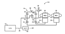
 図1は、本発明が好適に適用されるハイブリッド車両用駆動装置10(以下、単に駆動装置10という)の構成を説明する骨子図である。この図1に示すように、本実施例の駆動装置10は、例えばFF(前置エンジン前輪駆動)型車両等に好適に用いられる横置き用の装置であり、主動力源であるエンジン12、第1電動機MG1、第2電動機MG2、第1差動機構としての第1遊星歯車装置14、及び第2差動機構としての第2遊星歯車装置16を共通の中心軸CE上に備えて構成されている。前記駆動装置10は、中心軸CEに対して略対称的に構成されており、図1においては中心線の下半分を省略して図示している。以下の各実施例についても同様である。 FIG. 1 is a skeleton diagram illustrating the configuration of a hybrid vehicle drive device 10 (hereinafter simply referred to as drive device 10) to which the present invention is preferably applied. As shown in FIG. 1, the drive device 10 of the present embodiment is a device for horizontal use that is preferably used in, for example, an FF (front engine front wheel drive) type vehicle and the like, and an engine 12, which is a main power source, The first electric motor MG1, the second electric motor MG2, the first planetary gear device 14 as a first differential mechanism, and the second planetary gear device 16 as a second differential mechanism are provided on a common central axis CE. ing. The driving device 10 is configured substantially symmetrically with respect to the central axis CE, and the lower half of the central line is omitted in FIG. The same applies to each of the following embodiments.
 前記エンジン12は、例えば、気筒内噴射されるガソリン等の燃料の燃焼によって駆動力を発生させるガソリンエンジン等の内燃機関である。前記第1電動機MG1及び第2電動機MG2は、好適には、何れも駆動力を発生させるモータ(発動機)及び反力を発生させるジェネレータ(発電機)としての機能を有する所謂モータジェネレータであり、それぞれのステータ(固定子)18、22が非回転部材であるハウジング(ケース)26に固設されると共に、各ステータ18、22の内周側にロータ(回転子)20、24を備えて構成されている。 The engine 12 is, for example, an internal combustion engine such as a gasoline engine that generates driving force by combustion of fuel such as gasoline injected in a cylinder. The first electric motor MG1 and the second electric motor MG2 are preferably so-called motor generators each having a function as a motor (engine) for generating driving force and a generator (generator) for generating reaction force. Each stator (stator) 18, 22 is fixed to a housing (case) 26 that is a non-rotating member, and the rotor (rotor) 20, 24 is provided on the inner peripheral side of each stator 18, 22. Has been.
 前記第1遊星歯車装置14は、ギヤ比がρ1であるシングルピニオン型の遊星歯車装置であり、第1回転要素としてのサンギヤS1、ピニオンギヤP1を自転及び公転可能に支持する第2回転要素としてのキャリアC1、及びピニオンギヤP1を介してサンギヤS1と噛み合う第3回転要素としてのリングギヤR1を回転要素(要素)として備えている。前記第2遊星歯車装置16は、ギヤ比がρ2であるシングルピニオン型の遊星歯車装置であり、第1回転要素としてのサンギヤS2、ピニオンギヤP2を自転及び公転可能に支持する第2回転要素としてのキャリアC2、及びピニオンギヤP2を介してサンギヤS2と噛み合う第3回転要素としてのリングギヤR2を回転要素(要素)として備えている。 The first planetary gear unit 14 is a single pinion type planetary gear unit having a gear ratio of ρ1, and serves as a second rotating element that supports the sun gear S1 and the pinion gear P1 as the first rotating element so as to be capable of rotating and revolving. A ring gear R1 as a third rotating element that meshes with the sun gear S1 via the carrier C1 and the pinion gear P1 is provided as a rotating element (element). The second planetary gear device 16 is a single pinion type planetary gear device having a gear ratio of ρ2, and serves as a second rotating element that supports the sun gear S2 and the pinion gear P2 as the first rotating element so as to be capable of rotating and revolving. A ring gear R2 as a third rotating element that meshes with the sun gear S2 via the carrier C2 and the pinion gear P2 is provided as a rotating element (element).
 前記第1遊星歯車装置14のサンギヤS1は、前記第1電動機MG1のロータ20に連結されている。前記第1遊星歯車装置14のキャリアC1は、前記エンジン12のクランク軸と一体的に回転させられる入力軸28に連結されている。この入力軸28は、前記中心軸CEを軸心とするものであり、以下の実施例において、特に区別しない場合には、この中心軸CEの軸心の方向を軸方向(軸心方向)という。前記第1遊星歯車装置14のリングギヤR1は、出力回転部材である出力歯車30に連結されると共に、前記第2遊星歯車装置16のリングギヤR2と相互に連結されている。前記第2遊星歯車装置16のサンギヤS2は、前記第2電動機MG2のロータ24に連結されている。 The sun gear S1 of the first planetary gear unit 14 is connected to the rotor 20 of the first electric motor MG1. The carrier C1 of the first planetary gear unit 14 is connected to an input shaft 28 that is rotated integrally with the crankshaft of the engine 12. The input shaft 28 is centered on the central axis CE. In the following embodiments, the direction of the central axis of the central axis CE is referred to as an axial direction (axial direction) unless otherwise distinguished. . The ring gear R1 of the first planetary gear device 14 is connected to an output gear 30 that is an output rotating member, and is also connected to the ring gear R2 of the second planetary gear device 16. The sun gear S2 of the second planetary gear device 16 is connected to the rotor 24 of the second electric motor MG2.
 前記出力歯車30から出力された駆動力は、図示しない差動歯車装置及び車軸等を介して図示しない左右一対の駆動輪へ伝達される。一方、車両の走行路面から駆動輪に対して入力されるトルクは、前記差動歯車装置及び車軸等を介して前記出力歯車30から前記駆動装置10へ伝達(入力)される。前記入力軸28における前記エンジン12と反対側の端部には、例えばベーンポンプ等の機械式オイルポンプ32が連結されており、前記エンジン12の駆動に伴い後述する油圧制御回路60等の元圧とされる油圧が出力されるようになっている。このオイルポンプ32に加えて、電気エネルギにより駆動される電動式オイルポンプが設けられたものであってもよい。 The driving force output from the output gear 30 is transmitted to a pair of left and right driving wheels (not shown) via a differential gear device and an axle (not shown). On the other hand, torque input to the drive wheels from the road surface of the vehicle is transmitted (input) from the output gear 30 to the drive device 10 via the differential gear device and the axle. A mechanical oil pump 32 such as a vane pump is connected to an end portion of the input shaft 28 opposite to the engine 12, and an original pressure of a hydraulic control circuit 60 or the like to be described later when the engine 12 is driven. The hydraulic pressure is output. In addition to the oil pump 32, an electric oil pump driven by electric energy may be provided.
 前記第1遊星歯車装置14のキャリアC1と前記第2遊星歯車装置16のキャリアC2との間には、それらキャリアC1とC2との間を選択的に係合させる(キャリアC1とC2との間を断接する)クラッチCLが設けられている。前記第2遊星歯車装置16のキャリアC2と非回転部材である前記ハウジング26との間には、そのハウジング26に対して前記キャリアC2を選択的に係合(固定)させるブレーキBKが設けられている。これらのクラッチCL及びブレーキBKは、好適には、何れも油圧制御回路60から供給される油圧に応じて係合状態が制御される(係合乃至解放させられる)油圧式係合装置であり、例えば、湿式多板型の摩擦係合装置等が好適に用いられるが、噛合式の係合装置すなわち所謂ドグクラッチ(噛合クラッチ)であってもよい。更には、電磁式クラッチや磁粉式クラッチ等、電子制御装置40から供給される電気的な指令に応じて係合状態が制御される(係合乃至解放させられる)ものであってもよい。 The carrier C1 of the first planetary gear device 14 and the carrier C2 of the second planetary gear device 16 are selectively engaged between the carriers C1 and C2 (between the carriers C1 and C2). A clutch CL is provided. A brake BK for selectively engaging (fixing) the carrier C2 with respect to the housing 26 is provided between the carrier C2 of the second planetary gear device 16 and the housing 26 which is a non-rotating member. Yes. The clutch CL and the brake BK are preferably hydraulic engagement devices whose engagement states are controlled (engaged or released) according to the hydraulic pressure supplied from the hydraulic control circuit 60. For example, a wet multi-plate friction engagement device or the like is preferably used, but a meshing engagement device, that is, a so-called dog clutch (meshing clutch) may be used. Furthermore, an engagement state may be controlled (engaged or released) according to an electrical command supplied from the electronic control device 40, such as an electromagnetic clutch or a magnetic powder clutch.
 図1に示すように、前記駆動装置10において、前記第1遊星歯車装置14及び第2遊星歯車装置16は、それぞれ前記入力軸28と同軸上(中心軸CE上)に配置されており、且つ、前記中心軸CEの軸方向において対向する位置に配置されている。すなわち、前記中心軸CEの軸方向に関して、前記第1遊星歯車装置14は、前記第2遊星歯車装置16に対して前記エンジン12側に配置されている。前記中心軸CEの軸方向に関して、前記第1電動機MG1は、前記第1遊星歯車装置14に対して前記エンジン12側に配置されている。前記中心軸CEの軸方向に関して、前記第2電動機MG1は、前記第2遊星歯車装置16に対して前記エンジン12の反対側に配置されている。すなわち、前記第1電動機MG1、第2電動機MG2は、前記中心軸CEの軸方向に関して、前記第1遊星歯車装置14及び第2遊星歯車装置16を間に挟んで対向する位置に配置されている。すなわち、前記駆動装置10においては、前記中心軸CEの軸方向において、前記エンジン12側から前記第1電動機MG1、第1遊星歯車装置14、クラッチCL、第2遊星歯車装置16、ブレーキBK、第2電動機MG2の順でそれらの構成が同軸上に配置されている。 As shown in FIG. 1, in the driving device 10, the first planetary gear device 14 and the second planetary gear device 16 are arranged coaxially with the input shaft 28 (on the central axis CE), and , Are arranged at positions facing each other in the axial direction of the central axis CE. That is, with respect to the axial direction of the central axis CE, the first planetary gear device 14 is disposed on the engine 12 side with respect to the second planetary gear device 16. With respect to the axial direction of the central axis CE, the first electric motor MG1 is disposed on the engine 12 side with respect to the first planetary gear unit 14. With respect to the axial direction of the central axis CE, the second electric motor MG1 is disposed on the opposite side of the engine 12 with respect to the second planetary gear device 16. That is, the first electric motor MG1 and the second electric motor MG2 are arranged at positions facing each other with the first planetary gear device 14 and the second planetary gear device 16 interposed therebetween with respect to the axial direction of the central axis CE. . That is, in the drive device 10, in the axial direction of the central axis CE, the first electric motor MG1, the first planetary gear device 14, the clutch CL, the second planetary gear device 16, the brake BK, Those components are arranged on the same axis in the order of the two electric motors MG2.
 図2は、前記駆動装置10の駆動を制御するためにその駆動装置10に備えられた制御系統の要部を説明する図である。この図2に示す電子制御装置40は、CPU、ROM、RAM、及び入出力インターフェイス等を含んで構成され、RAMの一時記憶機能を利用しつつROMに予め記憶されたプログラムに従って信号処理を実行する所謂マイクロコンピュータであり、前記エンジン12の駆動制御や、前記第1電動機MG1及び第2電動機MG2に関するハイブリッド駆動制御をはじめとする前記駆動装置10の駆動に係る各種制御を実行する。すなわち、本実施例においては、前記電子制御装置40が前記駆動装置10の適用されたハイブリッド車両の駆動制御装置に相当する。この電子制御装置40は、前記エンジン12の出力制御用や前記第1電動機MG1及び第2電動機MG2の作動制御用といったように、必要に応じて各制御毎に個別の制御装置として構成される。 FIG. 2 is a diagram for explaining a main part of a control system provided in the driving device 10 in order to control the driving of the driving device 10. The electronic control unit 40 shown in FIG. 2 includes a CPU, a ROM, a RAM, an input / output interface, and the like, and executes signal processing in accordance with a program stored in advance in the ROM while using a temporary storage function of the RAM. The microcomputer is a so-called microcomputer, and executes various controls related to driving of the drive device 10 including drive control of the engine 12 and hybrid drive control related to the first electric motor MG1 and the second electric motor MG2. That is, in this embodiment, the electronic control device 40 corresponds to a drive control device for a hybrid vehicle to which the drive device 10 is applied. The electronic control device 40 is configured as an individual control device for each control as required, such as for output control of the engine 12 and for operation control of the first electric motor MG1 and the second electric motor MG2.
 図2に示すように、前記電子制御装置40には、前記駆動装置10の各部に設けられたセンサやスイッチ等から各種信号が供給されるように構成されている。すなわち、アクセル開度センサ42により運転者の出力要求量に対応する図示しないアクセルペダルの操作量であるアクセル開度ACCを表す信号、エンジン回転速度センサ44により前記エンジン12の回転速度であるエンジン回転速度NEを表す信号、MG1回転速度センサ46により前記第1電動機MG1の回転速度NMG1を表す信号、MG2回転速度センサ48により前記第2電動機MG2の回転速度NMG2を表す信号、出力回転速度センサ50により車速Vに対応する前記出力歯車30の回転速度NOUTを表す信号、油温センサ52により前記駆動装置10における各部へ供給される作動油の油温TOILを表す信号、及びシフトセンサ54により図示しないシフト操作装置の操作位置PSを表す信号等が、それぞれ上記電子制御装置40に供給される。 As shown in FIG. 2, the electronic control device 40 is configured to be supplied with various signals from sensors, switches, and the like provided in each part of the driving device 10. That is, a signal representing an accelerator opening degree A CC which is an operation amount of an accelerator pedal (not shown) corresponding to a driver's output request amount by the accelerator opening sensor 42, and an engine which is the rotation speed of the engine 12 by the engine rotation speed sensor 44. signal representative of the rotational speed N E, a signal indicative of the rotational speed N MG1 of the first electric motor MG1 by MG1 rotational speed sensor 46, a signal indicative of the rotational speed N MG2 of the second electric motor MG2 by MG2 rotational speed sensor 48, output rotation A signal representing the rotational speed N OUT of the output gear 30 corresponding to the vehicle speed V by the speed sensor 50, a signal representing the oil temperature T OIL of the hydraulic oil supplied to each part in the drive device 10 by the oil temperature sensor 52, and a shift signal or the like representing the operating position P S of the shift operating device (not shown) by the sensor 54 are each the electronic control unit 40 It is fed.
 前記電子制御装置40からは、前記駆動装置10の各部に作動指令が出力されるように構成されている。すなわち、前記エンジン12の出力を制御するエンジン出力制御指令として、燃料噴射装置による吸気配管等への燃料供給量を制御する燃料噴射量信号、点火装置による前記エンジン12の点火時期(点火タイミング)を指令する点火信号、電子スロットル弁のスロットル弁開度θTHを操作するためにスロットルアクチュエータへ供給される電子スロットル弁駆動信号、及びEGRバルブ34の開度(開閉)を制御するEGRバルブ駆動信号等が、そのエンジン12の出力を制御するエンジン制御装置56へ出力される。前記EGRバルブ34は、前記エンジン12の排気ガスの一部を吸気ガス中に循環させるEGR(Exhaust-Gas Recirculation:排気再循環)において、排気ガスの吸気側への循環量を制御する装置である。前記電子制御装置40からは、前記第1電動機MG1及び第2電動機MG2の作動を指令する指令信号がインバータ58へ出力され、そのインバータ58を介してバッテリからその指令信号に応じた電気エネルギが前記第1電動機MG1及び第2電動機MG2に供給されてそれら第1電動機MG1及び第2電動機MG2の出力(トルク)が制御される。前記第1電動機MG1及び第2電動機MG2により発電された電気エネルギが前記インバータ58を介してバッテリに供給され、そのバッテリに蓄積されるようになっている。前記クラッチCL、ブレーキBKの係合状態を制御する指令信号が油圧制御回路60に備えられたリニアソレノイド弁等の電磁制御弁へ供給され、それら電磁制御弁から出力される油圧が制御されることで前記クラッチCL、ブレーキBKの係合状態が制御されるようになっている。 The electronic control device 40 is configured to output an operation command to each part of the driving device 10. That is, as an engine output control command for controlling the output of the engine 12, a fuel injection amount signal for controlling a fuel supply amount to an intake pipe or the like by the fuel injection device, and an ignition timing (ignition timing) of the engine 12 by the ignition device An ignition signal to be commanded, an electronic throttle valve drive signal supplied to the throttle actuator for operating the throttle valve opening θ TH of the electronic throttle valve, an EGR valve drive signal for controlling the opening (opening / closing) of the EGR valve 34, etc. Is output to the engine control device 56 that controls the output of the engine 12. The EGR valve 34 is a device that controls the amount of exhaust gas circulated to the intake side in EGR (Exhaust-Gas Recirculation) in which a part of the exhaust gas of the engine 12 is circulated in the intake gas. . From the electronic control unit 40, a command signal for commanding the operation of the first motor MG1 and the second motor MG2 is output to the inverter 58, and the electric energy corresponding to the command signal is transmitted from the battery via the inverter 58. The first motor MG1 and the second motor MG2 are supplied to control the outputs (torque) of the first motor MG1 and the second motor MG2. Electric energy generated by the first electric motor MG1 and the second electric motor MG2 is supplied to the battery via the inverter 58 and stored in the battery. A command signal for controlling the engagement state of the clutch CL and the brake BK is supplied to an electromagnetic control valve such as a linear solenoid valve provided in the hydraulic control circuit 60, and the hydraulic pressure output from the electromagnetic control valve is controlled. Thus, the engagement state of the clutch CL and the brake BK is controlled.
 前記駆動装置10は、前記第1電動機MG1及び第2電動機MG2を介して運転状態が制御されることにより、入力回転速度と出力回転速度の差動状態が制御される電気式差動部として機能する。例えば、前記第1電動機MG1により発電された電気エネルギを前記インバータ58を介してバッテリや第2電動機MG2へ供給する。これにより、前記エンジン12の動力の主要部は機械的に前記出力歯車30へ伝達される一方、その動力の一部は前記第1電動機MG1の発電のために消費されてそこで電気エネルギに変換され、前記インバータ58を通してその電気エネルギが前記第2電動機MG2へ供給される。そして、その第2電動機MG2が駆動されて第2電動機MG2から出力された動力が前記出力歯車30へ伝達される。この電気エネルギの発生から第2電動機MG2で消費されるまでに関連する機器により、前記エンジン12の動力の一部を電気エネルギに変換し、その電気エネルギを機械的エネルギに変換するまでの電気パスが構成される。 The drive device 10 functions as an electric differential unit that controls the differential state between the input rotation speed and the output rotation speed by controlling the operation state via the first electric motor MG1 and the second electric motor MG2. To do. For example, the electric energy generated by the first electric motor MG1 is supplied to the battery and the second electric motor MG2 via the inverter 58. As a result, the main part of the power of the engine 12 is mechanically transmitted to the output gear 30, while a part of the power is consumed for power generation of the first electric motor MG 1 and is converted into electric energy there. The electric energy is supplied to the second electric motor MG2 through the inverter 58. Then, the second electric motor MG2 is driven, and the power output from the second electric motor MG2 is transmitted to the output gear 30. Electrical path from conversion of part of the power of the engine 12 into electrical energy and conversion of the electrical energy into mechanical energy by related equipment from the generation of the electrical energy to consumption by the second electric motor MG2. Is configured.
 以上のように構成された駆動装置10が適用されたハイブリッド車両においては、前記エンジン12、第1電動機MG1、及び第2電動機MG2の駆動状態、及び前記クラッチCL、ブレーキBKの係合状態等に応じて、複数の走行モードの何れかが選択的に成立させられる。図3は、前記駆動装置10において成立させられる5種類の走行モードそれぞれにおける前記クラッチCL、ブレーキBKの係合状態を示す係合表であり、係合を「○」で、解放を空欄でそれぞれ示している。この図3に示す走行モード「EV-1」、「EV-2」は、何れも前記エンジン12の運転が停止させられると共に、前記第1電動機MG1及び第2電動機MG2の少なくとも一方を走行用の駆動源として用いるEV走行モードである。「HV-1」、「HV-2」、「HV-3」は、何れも前記エンジン12を例えば走行用の駆動源として駆動させると共に、前記第1電動機MG1及び第2電動機MG2により必要に応じて駆動乃至発電等を行うハイブリッド走行モードである。このハイブリッド走行モードにおいて、前記第1電動機MG1及び第2電動機MG2の少なくとも一方により反力を発生させるものであってもよく、無負荷の状態で空転させるものであってもよい。 In the hybrid vehicle to which the drive device 10 configured as described above is applied, the driving state of the engine 12, the first electric motor MG1, and the second electric motor MG2 and the engagement state of the clutch CL and the brake BK are set. In response, one of the plurality of travel modes is selectively established. FIG. 3 is an engagement table showing the engagement states of the clutch CL and the brake BK in each of the five types of travel modes established in the drive device 10, wherein the engagement is “◯” and the release is blank. Show. In each of the travel modes “EV-1” and “EV-2” shown in FIG. 3, the operation of the engine 12 is stopped, and at least one of the first electric motor MG1 and the second electric motor MG2 is used for traveling. This is an EV travel mode used as a drive source. “HV-1”, “HV-2”, and “HV-3” all drive the engine 12 as a driving source for traveling, for example, and the first motor MG1 and the second motor MG2 as required. This is a hybrid travel mode for driving or generating power. In this hybrid travel mode, a reaction force may be generated by at least one of the first electric motor MG1 and the second electric motor MG2, or may be idled in an unloaded state.
 図3に示すように、前記駆動装置10においては、前記エンジン12の運転が停止させられると共に、前記第1電動機MG1及び第2電動機MG2の少なくとも一方を走行用の駆動源として用いるEV走行モードにおいて、前記ブレーキBKが係合されると共に前記クラッチCLが解放されることでモード1(走行モード1)である「EV-1」が、前記ブレーキBK及びクラッチCLが共に係合されることでモード2(走行モード2)である「EV-2」がそれぞれ成立させられる。前記エンジン12を例えば走行用の駆動源として駆動させると共に、前記第1電動機MG1及び第2電動機MG2により必要に応じて駆動乃至発電等を行うハイブリッド走行モードにおいて、前記ブレーキBKが係合されると共に前記クラッチCLが解放されることでモード3(走行モード3)である「HV-1」が、前記ブレーキBKが解放されると共に前記クラッチCLが係合されることでモード4(走行モード4)である「HV-2」が、前記ブレーキBK及びクラッチCLが共に解放されることでモード5(走行モード5)である「HV-3」がそれぞれ成立させられる。 As shown in FIG. 3, in the driving apparatus 10, the operation of the engine 12 is stopped, and in the EV traveling mode in which at least one of the first electric motor MG <b> 1 and the second electric motor MG <b> 2 is used as a driving source for traveling. When the brake BK is engaged and the clutch CL is disengaged, mode 1 (travel mode 1) is “EV-1”, and when the brake BK and the clutch CL are both engaged, the mode is 2 (travel mode 2), “EV-2”, is established. In the hybrid traveling mode in which the engine 12 is driven as a driving source for traveling, for example, and the first electric motor MG1 and the second electric motor MG2 are driven or generated as necessary, the brake BK is engaged. “HV-1” which is mode 3 (travel mode 3) by releasing the clutch CL, and mode 4 (travel mode 4) by releasing the brake BK and engaging the clutch CL. "HV-2" is established, and "HV-3" which is mode 5 (travel mode 5) is established by releasing both the brake BK and the clutch CL.
 図4~図7は、前記駆動装置10(第1遊星歯車装置14及び第2遊星歯車装置16)において、前記クラッチCL及びブレーキBKそれぞれの係合状態に応じて連結状態が異なる各回転要素の回転速度の相対関係を直線上で表すことができる共線図を示しており、横軸方向において前記第1遊星歯車装置14及び第2遊星歯車装置16のギヤ比ρの相対関係を示し、縦軸方向において相対的回転速度を示す二次元座標である。車両前進時における前記出力歯車30の回転方向を正の方向(正回転)として各回転速度を表している。横線X1は回転速度零を示している。縦線Y1~Y4は、左から順に実線Y1が前記第1遊星歯車装置14のサンギヤS1(第1電動機MG1)、破線Y2が前記第2遊星歯車装置16のサンギヤS2(第2電動機MG2)、実線Y3が前記第1遊星歯車装置14のキャリアC1(エンジン12)、破線Y3′が前記第2遊星歯車装置16のキャリアC2、実線Y4が前記第1遊星歯車装置14のリングギヤR1(出力歯車30)、破線Y4′が前記第2遊星歯車装置16のリングギヤR2それぞれの相対回転速度を示している。図4~図7においては、縦線Y3及びY3′、縦線Y4及びY4′をそれぞれ重ねて表している。ここで、前記リングギヤR1及びR2は相互に連結されているため、縦線Y4、Y4′にそれぞれ示すリングギヤR1及びR2の相対回転速度は等しい。 FIGS. 4 to 7 show the rotation elements of the driving device 10 (the first planetary gear device 14 and the second planetary gear device 16) that have different coupling states depending on the engagement states of the clutch CL and the brake BK. FIG. 2 shows a collinear chart that can represent the relative relationship of rotational speed on a straight line, showing the relative relationship of the gear ratio ρ of the first planetary gear device 14 and the second planetary gear device 16 in the horizontal axis direction, It is a two-dimensional coordinate which shows a relative rotational speed in an axial direction. The rotational speeds of the output gears 30 when the vehicle moves forward are represented as positive directions (positive rotations). A horizontal line X1 indicates zero rotation speed. In the vertical lines Y1 to Y4, in order from the left, the solid line Y1 indicates the sun gear S1 (first electric motor MG1) of the first planetary gear unit 14, the broken line Y2 indicates the sun gear S2 (second electric motor MG2) of the second planetary gear unit 16, The solid line Y3 is the carrier C1 (engine 12) of the first planetary gear unit 14, the broken line Y3 'is the carrier C2 of the second planetary gear unit 16, and the solid line Y4 is the ring gear R1 (output gear 30) of the first planetary gear unit 14. ), The broken line Y4 ′ indicates the relative rotational speed of each ring gear R2 of the second planetary gear unit 16. 4 to 7, the vertical lines Y3 and Y3 ′ and the vertical lines Y4 and Y4 ′ are overlaid. Here, since the ring gears R1 and R2 are connected to each other, the relative rotational speeds of the ring gears R1 and R2 indicated by the vertical lines Y4 and Y4 ′ are equal.
 図4~図7においては、前記第1遊星歯車装置14における3つの回転要素の相対的な回転速度を実線L1で、前記第2遊星歯車装置16における3つの回転要素の相対的な回転速度を破線L2でそれぞれ示している。前記縦線Y1~Y4(Y2~Y4′)の間隔は、前記第1遊星歯車装置14及び第2遊星歯車装置16の各ギヤ比ρ1、ρ2に応じて定められている。すなわち、前記第1遊星歯車装置14における3つの回転要素に対応する縦線Y1、Y3、Y4に関して、サンギヤS1とキャリアC1との間が1に対応するものとされ、キャリアC1とリングギヤR1との間がρ1に対応するものとされる。前記第2遊星歯車装置16における3つの回転要素に対応する縦線Y2、Y3′、Y4′に関して、サンギヤS2とキャリアC2との間が1に対応するものとされ、キャリアC2とリングギヤR2との間がρ2に対応するものとされる。すなわち、前記駆動装置10において、好適には、前記第1遊星歯車装置14のギヤ比ρ1よりも前記第2遊星歯車装置16のギヤ比ρ2の方が大きい(ρ2>ρ1)。以下、図4~図7を用いて前記駆動装置10における各走行モードについて説明する。 4 to 7, the relative rotational speeds of the three rotating elements in the first planetary gear device 14 are indicated by a solid line L1, and the relative rotational speeds of the three rotating elements in the second planetary gear device 16 are indicated by solid lines L1. Each is indicated by a broken line L2. The intervals between the vertical lines Y1 to Y4 (Y2 to Y4 ′) are determined according to the gear ratios ρ1 and ρ2 of the first planetary gear device 14 and the second planetary gear device 16. That is, regarding the vertical lines Y1, Y3, Y4 corresponding to the three rotating elements in the first planetary gear device 14, the space between the sun gear S1 and the carrier C1 corresponds to 1, and the carrier C1 and the ring gear R1 The interval corresponds to ρ1. Regarding the vertical lines Y2, Y3 ', Y4' corresponding to the three rotating elements in the second planetary gear device 16, the space between the sun gear S2 and the carrier C2 corresponds to 1, and the carrier C2 and the ring gear R2 The interval corresponds to ρ2. That is, in the drive device 10, the gear ratio ρ2 of the second planetary gear device 16 is preferably larger than the gear ratio ρ1 of the first planetary gear device 14 (ρ2> ρ1). Hereinafter, each traveling mode in the driving apparatus 10 will be described with reference to FIGS.
 図3に示す「EV-1」は、前記駆動装置10におけるモード1(走行モード1)に相当するものであり、好適には、前記エンジン12の運転が停止させられると共に、前記第2電動機MG2が走行用の駆動源として用いられるEV走行モードである。図4は、このモード1に対応する共線図であり、この共線図を用いて説明すれば、前記クラッチCLが解放されることで前記第1遊星歯車装置14のキャリアC1と前記第2遊星歯車装置16のキャリアC2との相対回転が可能とされている。前記ブレーキBKが係合されることで前記第2遊星歯車装置16のキャリアC2が非回転部材である前記ハウジング26に対して連結(固定)され、その回転速度が零とされている。このモード1においては、前記第2遊星歯車装置16において、前記サンギヤS2の回転方向と前記リングギヤR2の回転方向とが逆方向となり、前記第2電動機MG2により負のトルク(負の方向のトルク)が出力されると、そのトルクにより前記リングギヤR2すなわち出力歯車30は正の方向に回転させられる。すなわち、前記第2電動機MG2により負のトルクを出力させることにより、前記駆動装置10の適用されたハイブリッド車両を前進走行させることができる。この場合において、好適には、前記第1電動機MG1は空転させられる。このモード1では、前記キャリアC1及びC2の相対回転が許容されると共に、そのキャリアC2が非回転部材に連結された所謂THS(Toyota Hybrid System)を搭載した車両におけるEV走行と同様のEV走行制御を行うことができる。 “EV-1” shown in FIG. 3 corresponds to mode 1 (travel mode 1) in the drive device 10, and preferably the operation of the engine 12 is stopped and the second electric motor MG2 is stopped. Is an EV traveling mode used as a driving source for traveling. FIG. 4 is a collinear diagram corresponding to this mode 1, and will be described using this collinear diagram. When the clutch CL is released, the carrier C1 and the second planetary gear device 14 of the first planetary gear unit 14 are disengaged. The planetary gear device 16 can rotate relative to the carrier C2. Engagement of the brake BK causes the carrier C2 of the second planetary gear device 16 to be connected (fixed) to the housing 26, which is a non-rotating member, so that its rotational speed is zero. In this mode 1, in the second planetary gear device 16, the rotation direction of the sun gear S2 and the rotation direction of the ring gear R2 are opposite to each other, and negative torque (torque in the negative direction) is generated by the second electric motor MG2. Is output, the torque causes the ring gear R2, that is, the output gear 30, to rotate in the positive direction. That is, by outputting negative torque by the second electric motor MG2, the hybrid vehicle to which the drive device 10 is applied can be caused to travel forward. In this case, preferably, the first electric motor MG1 is idled. In this mode 1, the relative rotation of the carriers C1 and C2 is allowed, and EV travel control similar to EV travel in a vehicle equipped with a so-called THS (Toyota Hybrid System) in which the carrier C2 is connected to a non-rotating member. It can be performed.
 図3に示す「EV-2」は、前記駆動装置10におけるモード2(走行モード2)に相当するものであり、好適には、前記エンジン12の運転が停止させられると共に、前記第1電動機MG1及び第2電動機MG2の少なくとも一方が走行用の駆動源として用いられるEV走行モードである。図5は、このモード2に対応する共線図であり、この共線図を用いて説明すれば、前記クラッチCLが係合されることで前記第1遊星歯車装置14のキャリアC1と前記第2遊星歯車装置16のキャリアC2との相対回転が不能とされている。更に、前記ブレーキBKが係合されることで前記第2遊星歯車装置16のキャリアC2及びそのキャリアC2に係合された前記第1遊星歯車装置14のキャリアC1が非回転部材である前記ハウジング26に対して連結(固定)され、その回転速度が零とされている。このモード2においては、前記第1遊星歯車装置14において、前記サンギヤS1の回転方向と前記リングギヤR1の回転方向とが逆方向となると共に、前記第2遊星歯車装置16において、前記サンギヤS2の回転方向と前記リングギヤR2の回転方向とが逆方向となる。すなわち、前記第1電動機MG1乃至前記第2電動機MG2により負のトルク(負の方向のトルク)が出力されると、そのトルクにより前記リングギヤR1及びR2すなわち出力歯車30は正の方向に回転させられる。すなわち、前記第1電動機MG1及び第2電動機MG2の少なくとも一方により負のトルクを出力させることにより、前記駆動装置10の適用されたハイブリッド車両を前進走行させることができる。 “EV-2” shown in FIG. 3 corresponds to mode 2 (traveling mode 2) in the driving apparatus 10, and preferably the operation of the engine 12 is stopped and the first electric motor MG1 is stopped. In addition, this is an EV traveling mode in which at least one of the second electric motor MG2 is used as a driving source for traveling. FIG. 5 is a collinear diagram corresponding to this mode 2. If the collinear diagram is used to explain, the carrier C1 of the first planetary gear device 14 and the first planetary gear device 14 are engaged by engaging the clutch CL. The relative rotation of the two planetary gear unit 16 with the carrier C2 is disabled. Further, when the brake BK is engaged, the carrier C2 of the second planetary gear device 16 and the carrier C1 of the first planetary gear device 14 engaged with the carrier C2 are non-rotating members. Are connected (fixed) to each other and their rotational speed is zero. In this mode 2, the rotation direction of the sun gear S1 is opposite to the rotation direction of the ring gear R1 in the first planetary gear device 14, and the rotation of the sun gear S2 is reversed in the second planetary gear device 16. The direction and the rotation direction of the ring gear R2 are opposite to each other. That is, when negative torque (torque in the negative direction) is output from the first electric motor MG1 to the second electric motor MG2, the ring gears R1 and R2, that is, the output gear 30 are rotated in the positive direction by the torque. . That is, the hybrid vehicle to which the drive device 10 is applied can be caused to travel forward by outputting negative torque by at least one of the first electric motor MG1 and the second electric motor MG2.
 前記モード2においては、前記第1電動機MG1及び第2電動機MG2の少なくとも一方により発電を行う形態を成立させることもできる。この形態においては、前記第1電動機MG1及び第2電動機MG2の一方或いは両方により走行用の駆動力(トルク)を分担して発生させることが可能となり、各電動機を効率の良い動作点で動作させたり、熱によるトルク制限等の制約を緩和する走行等が可能となる。更に、バッテリの充電状態が満充電の場合等、回生による発電が許容されない場合に、前記第1電動機MG1及び第2電動機MG2の一方或いは両方を空転させることも可能である。すなわち、前記モード2においては、幅広い走行条件においてEV走行を行うことや、長時間継続してEV走行を行うことが可能となる。従って、前記モード2は、プラグインハイブリッド車両等、EV走行を行う割合が高いハイブリッド車両において好適に採用される。 In the mode 2, it is possible to establish a mode in which power generation is performed by at least one of the first electric motor MG1 and the second electric motor MG2. In this form, it becomes possible to share and generate driving force (torque) for traveling by one or both of the first electric motor MG1 and the second electric motor MG2, and each electric motor is operated at an efficient operating point. Or running that relaxes restrictions such as torque limitation due to heat. Furthermore, it is possible to idle one or both of the first electric motor MG1 and the second electric motor MG2 when power generation by regeneration is not allowed, such as when the battery is fully charged. That is, in the mode 2, it is possible to perform EV traveling under a wide range of traveling conditions, or to perform EV traveling continuously for a long time. Therefore, the mode 2 is suitably employed in a hybrid vehicle having a high EV traveling ratio such as a plug-in hybrid vehicle.
 図3に示す「HV-1」は、前記駆動装置10におけるモード3(走行モード3)に相当するものであり、好適には、前記エンジン12が駆動されて走行用の駆動源として用いられると共に、必要に応じて前記第1電動機MG1及び第2電動機MG2による駆動乃至発電が行われるハイブリッド走行モードである。図4の共線図は、このモード3に対応するものでもあり、この共線図を用いて説明すれば、前記クラッチCLが解放されることで前記第1遊星歯車装置14のキャリアC1と前記第2遊星歯車装置16のキャリアC2との相対回転が可能とされている。前記ブレーキBKが係合されることで前記第2遊星歯車装置16のキャリアC2が非回転部材である前記ハウジング26に対して連結(固定)され、その回転速度が零とされている。このモード3においては、前記エンジン12が駆動させられ、その出力トルクにより前記出力歯車30が回転させられる。この際、前記第1遊星歯車装置14において、前記第1電動機MG1により反力トルクを出力させることで、前記エンジン12からの出力の前記出力歯車30への伝達が可能とされる。前記第2遊星歯車装置16においては、前記ブレーキBKが係合されていることで、前記サンギヤS2の回転方向と前記リングギヤR2の回転方向とが逆方向となる。すなわち、前記第2電動機MG2により負のトルク(負の方向のトルク)が出力されると、そのトルクにより前記リングギヤR1及びR2すなわち出力歯車30は正の方向に回転させられる。 “HV-1” shown in FIG. 3 corresponds to mode 3 (traveling mode 3) in the driving device 10, and is preferably used as a driving source for traveling when the engine 12 is driven. This is a hybrid travel mode in which driving or power generation is performed by the first electric motor MG1 and the second electric motor MG2 as necessary. The collinear diagram of FIG. 4 also corresponds to this mode 3. If described using this collinear diagram, the carrier C1 of the first planetary gear device 14 and the carrier C1 are released by releasing the clutch CL. The second planetary gear device 16 can rotate relative to the carrier C2. Engagement of the brake BK causes the carrier C2 of the second planetary gear device 16 to be connected (fixed) to the housing 26, which is a non-rotating member, so that its rotational speed is zero. In mode 3, the engine 12 is driven, and the output gear 30 is rotated by the output torque. At this time, in the first planetary gear unit 14, the output torque from the engine 12 can be transmitted to the output gear 30 by causing the first electric motor MG 1 to output a reaction torque. In the second planetary gear unit 16, the rotation direction of the sun gear S2 and the rotation direction of the ring gear R2 are opposite because the brake BK is engaged. That is, when a negative torque (torque in the negative direction) is output by the second electric motor MG2, the ring gears R1 and R2, that is, the output gear 30 are rotated in the positive direction by the torque.
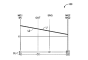
 図3に示す「HV-2」は、前記駆動装置10におけるモード4(走行モード4)に相当するものであり、好適には、前記エンジン12が駆動されて走行用の駆動源として用いられると共に、必要に応じて前記第1電動機MG1及び第2電動機MG2による駆動乃至発電が行われるハイブリッド走行モードである。図6は、このモード4に対応する共線図であり、この共線図を用いて説明すれば、前記クラッチCLが係合されることで前記第1遊星歯車装置14のキャリアC1と前記第2遊星歯車装置16のキャリアC2との相対回転が不能とされており、前記キャリアC1及びC2が一体的に回転させられる1つの回転要素として動作する。前記リングギヤR1及びR2は相互に連結されていることで、それらリングギヤR1及びR2は一体的に回転させられる1つの回転要素として動作する。すなわち、前記モード4において、前記駆動装置10における前記第1遊星歯車装置14及び第2遊星歯車装置16における回転要素は、全体として4つの回転要素を備えた差動機構として機能する。すなわち、図6において紙面向かって左から順に示す4つの回転要素であるサンギヤS1(第1電動機MG1)、サンギヤS2(第2電動機MG2)、相互に連結されたキャリアC1及びC2(エンジン12)、相互に連結されたリングギヤR1及びR2(出力歯車30)の順に結合した複合スプリットモードとなる。 “HV-2” shown in FIG. 3 corresponds to mode 4 (travel mode 4) in the drive device 10, and is preferably used as a drive source for travel when the engine 12 is driven. This is a hybrid travel mode in which driving or power generation is performed by the first electric motor MG1 and the second electric motor MG2 as necessary. FIG. 6 is a collinear diagram corresponding to the mode 4, and will be described using this collinear diagram. When the clutch CL is engaged, the carrier C1 of the first planetary gear unit 14 and the first The relative rotation of the two planetary gear unit 16 with the carrier C2 is disabled, and the carriers C1 and C2 operate as one rotating element that is rotated integrally. Since the ring gears R1 and R2 are connected to each other, the ring gears R1 and R2 operate as one rotating element that is rotated integrally. That is, in the mode 4, the rotating elements in the first planetary gear device 14 and the second planetary gear device 16 in the driving device 10 function as a differential mechanism including four rotating elements as a whole. That is, four gears in order from the left in FIG. 6 are the sun gear S1 (first electric motor MG1), the sun gear S2 (second electric motor MG2), the carriers C1 and C2 (engine 12) connected to each other, A composite split mode is obtained in which ring gears R1 and R2 (output gear 30) connected to each other are connected in this order.
 図6に示すように、前記モード4において、好適には、前記第1遊星歯車装置14及び第2遊星歯車装置16における各回転要素の共線図における並び順が、縦線Y1で示すサンギヤS1、縦線Y2で示すサンギヤS2、縦線Y3(Y3′)で示すキャリアC1及びC2、縦線Y4(Y4′)で示すリングギヤR1及びR2の順となる。前記第1遊星歯車装置14及び第2遊星歯車装置16それぞれのギヤ比ρ1、ρ2は、共線図において図6に示すように前記サンギヤS1に対応する縦線Y1と前記サンギヤS2に対応する縦線Y2とが上記の並び順となるように、すなわち縦線Y1と縦線Y3との間隔が、縦線Y2と縦線Y3′との間隔よりも広くなるように定められている。換言すれば、サンギヤS1、S2とキャリアC1、C2との間が1に対応するものとされ、キャリアC1、C2とリングギヤR1、R2との間がρ1、ρ2に対応することから、前記駆動装置10においては、前記第1遊星歯車装置14のギヤ比ρ1よりも前記第2遊星歯車装置16のギヤ比ρ2の方が大きい。 As shown in FIG. 6, in the mode 4, it is preferable that the arrangement order of the rotating elements in the first planetary gear device 14 and the second planetary gear device 16 in the alignment chart is a sun gear S1 indicated by a vertical line Y1. The sun gear S2 indicated by the vertical line Y2, the carriers C1 and C2 indicated by the vertical line Y3 (Y3 ′), and the ring gears R1 and R2 indicated by the vertical line Y4 (Y4 ′) are arranged in this order. The gear ratios ρ1 and ρ2 of the first planetary gear device 14 and the second planetary gear device 16 are respectively shown in FIG. 6 in the collinear diagram as a vertical line Y1 corresponding to the sun gear S1 and a vertical line corresponding to the sun gear S2. It is determined that the line Y2 is arranged in the above-described order, that is, the interval between the vertical line Y1 and the vertical line Y3 is wider than the interval between the vertical line Y2 and the vertical line Y3 ′. In other words, the sun gears S1 and S2 and the carriers C1 and C2 correspond to 1, and the carriers C1 and C2 and the ring gears R1 and R2 correspond to ρ1 and ρ2. 10, the gear ratio ρ2 of the second planetary gear device 16 is larger than the gear ratio ρ1 of the first planetary gear device 14.
 前記モード4においては、前記クラッチCLが係合されることで前記第1遊星歯車装置14のキャリアC1と前記第2遊星歯車装置16のキャリアC2とが連結されており、それらキャリアC1及びC2が一体的に回転させられる。このため、前記エンジン12の出力に対して、前記第1電動機MG1及び第2電動機MG2の何れによっても反力を受けることができる。すなわち、前記エンジン12の駆動に際して、その反力を前記第1電動機MG1及び第2電動機MG2の一方乃至両方で分担して受けることが可能となり、効率の良い動作点で動作させたり、熱によるトルク制限等の制約を緩和する走行等が可能となる。 In the mode 4, when the clutch CL is engaged, the carrier C1 of the first planetary gear device 14 and the carrier C2 of the second planetary gear device 16 are connected, and the carriers C1 and C2 are connected to each other. It can be rotated integrally. For this reason, the reaction force can be applied to the output of the engine 12 by either the first electric motor MG1 or the second electric motor MG2. That is, when the engine 12 is driven, the reaction force can be shared by one or both of the first electric motor MG1 and the second electric motor MG2, and the engine 12 can be operated at an efficient operating point, or the torque caused by heat. It is possible to run to ease restrictions such as restrictions.
 例えば、前記第1電動機MG1及び第2電動機MG2のうち、効率良く動作できる方の電動機により優先的に反力を受けるように制御することで、効率の向上を図ることができる。例えば、比較的車速Vが高い高車速時であり且つ比較的エンジン回転速度NEが低い低回転時には、前記第1電動機MG1の回転速度NMG1が負の値すなわち負回転となる場合がある。斯かる場合において、前記第1電動機MG1により前記エンジン12の反力を受けることを考えると、その第1電動機MG1により電力を消費して負トルクを発生させる逆転力行の状態となり、効率低下につながるおそれがある。ここで、図6から明らかなように、前記駆動装置10においては、縦線Y2で示す前記第2電動機MG2の回転速度は、縦線Y1で示す前記第1電動機MG1の回転速度に比べて負の値をとり難く、正回転の状態で前記エンジン12の反力を受けることができる場合が多い。従って、前記第1電動機MG1の回転速度が負の値である場合等において、前記第2電動機MG2により優先的に前記エンジン12の反力を受けるように制御することで、効率向上による燃費の向上を図ることができる。更に、前記第1電動機MG1及び第2電動機MG2の何れかにおいて熱によるトルク制限がなされた場合に、トルク制限がなされていない電動機の回生乃至出力によって駆動力をアシストすることで、前記エンジン12の駆動に必要な反力を確保すること等が可能とされる。 For example, the efficiency can be improved by controlling the first motor MG1 and the second motor MG2 so as to receive the reaction force preferentially by the motor that can operate efficiently. For example, relatively vehicle speed V is high high-speed drive and at the time of relatively engine rotational speed N E is lower low rotation, there is a case where the rotational speed N MG1 of the first electric motor MG1 is a negative value or negative rotation. In such a case, considering that the reaction force of the engine 12 is received by the first electric motor MG1, the first electric motor MG1 is in a reverse power running state in which power is consumed and negative torque is generated, leading to a reduction in efficiency. There is a fear. Here, as is apparent from FIG. 6, in the driving device 10, the rotational speed of the second electric motor MG2 indicated by the vertical line Y2 is negative compared to the rotational speed of the first electric motor MG1 indicated by the vertical line Y1. It is often difficult to take the value of and the reaction force of the engine 12 can be received in the forward rotation state. Therefore, when the rotational speed of the first electric motor MG1 is a negative value, the fuel efficiency is improved by improving the efficiency by controlling the second electric motor MG2 to receive the reaction force of the engine 12 preferentially. Can be achieved. Further, when torque is limited by heat in either the first electric motor MG1 or the second electric motor MG2, the driving force is assisted by regeneration or output of an electric motor that is not torque limited, so that the engine 12 It is possible to ensure a reaction force necessary for driving.
 図8は、前記駆動装置10における伝達効率を説明する図であり、横軸に変速比を、縦軸に理論伝達効率をそれぞれ示している。この図8に示す変速比は、前記第1遊星歯車装置14及び第2遊星歯車装置16における、出力側回転速度に対する入力側回転速度の比すなわち減速比であり、例えば、前記出力歯車30の回転速度(リングギヤR1、R2の回転速度)に対する前記キャリアC1等の入力回転部材の回転速度の比に相当する。図8に示す横軸においては、紙面向かって左側が変速比の小さいハイギヤ側であり、右側が変速比の大きいローギヤ側となる。図8に示す理論伝達効率は、前記駆動装置10における伝達効率の理論値であり、前記第1遊星歯車装置14、第2遊星歯車装置16に入力される動力が電気パスを介さずに機械的な伝達によって全て前記出力歯車30へ伝達される場合に最大効率1.0となる。 FIG. 8 is a diagram for explaining the transmission efficiency in the drive device 10, wherein the horizontal axis represents the transmission ratio and the vertical axis represents the theoretical transmission efficiency. The gear ratio shown in FIG. 8 is the ratio of the input side rotational speed to the output side rotational speed, that is, the reduction ratio in the first planetary gear device 14 and the second planetary gear device 16, for example, the rotation of the output gear 30. This corresponds to the ratio of the rotational speed of the input rotary member such as the carrier C1 to the speed (rotational speed of the ring gears R1 and R2). In the horizontal axis shown in FIG. 8, the left side of the drawing is the high gear side with a small gear ratio, and the right side is the low gear side with a large gear ratio. The theoretical transmission efficiency shown in FIG. 8 is a theoretical value of the transmission efficiency in the drive device 10, and the power input to the first planetary gear device 14 and the second planetary gear device 16 is mechanical without passing through an electrical path. The maximum efficiency is 1.0 when all of the signals are transmitted to the output gear 30 by simple transmission.
 図8では、前記駆動装置10におけるモード3(HV-1)時の伝達効率を一点鎖線で、モード4(HV-2)時の伝達効率を実線でそれぞれ示している。この図8に示すように、前記駆動装置10におけるモード3(HV-1)時の伝達効率は、変速比γ1において最大効率となる。この変速比γ1において、前記第1電動機MG1(サンギヤS1)の回転速度は零となるものであり、その第1電動機MG1において反力を受けることによる電気パスは零となり、機械的な動力伝達のみによって前記エンジン12乃至前記第2電動機MG2から出力歯車30へ動力を伝達することができる動作点となる。以下、このように電気パスがゼロの高効率動作点をメカニカルポイント(機械伝達ポイント)という。前記変速比γ1は、オーバードライブ側の変速比すなわち1よりも小さな変速比であり、以下、この変速比γ1を第1機械伝達変速比γ1という。図8に示すように、前記モード3時の伝達効率は、変速比が前記第1機械伝達変速比γ1よりもローギヤ側の値となるに従い緩やかに低下する一方、変速比が前記第1機械伝達変速比γ1よりもハイギヤ側の値となるに従いローギヤ側よりも急激に低下する。 In FIG. 8, the transmission efficiency in the mode 3 (HV-1) in the driving device 10 is indicated by a one-dot chain line, and the transmission efficiency in the mode 4 (HV-2) is indicated by a solid line. As shown in FIG. 8, the transmission efficiency in the mode 3 (HV-1) in the driving device 10 is the maximum efficiency at the speed ratio γ1. At this speed ratio γ1, the rotational speed of the first electric motor MG1 (sun gear S1) becomes zero, and the electric path caused by receiving the reaction force in the first electric motor MG1 becomes zero, and only mechanical power transmission is performed. Thus, an operating point at which power can be transmitted from the engine 12 to the second electric motor MG2 to the output gear 30 is obtained. Hereinafter, such a high-efficiency operating point with zero electrical path is referred to as a mechanical point (mechanical transmission point). The gear ratio γ1 is a gear ratio on the overdrive side, that is, a gear ratio smaller than 1. Hereinafter, the gear ratio γ1 is referred to as a first mechanical transmission gear ratio γ1. As shown in FIG. 8, the transmission efficiency in the mode 3 gradually decreases as the gear ratio becomes a value on the low gear side with respect to the first machine transmission gear ratio γ1, while the gear ratio becomes the first machine transmission. As it becomes a value on the high gear side with respect to the gear ratio γ1, it decreases more rapidly than on the low gear side.
 図8に示すように、前記駆動装置10におけるモード4(HV-2)においては、前記クラッチCLの係合により構成された4つの回転要素において図6の共線図に係る前記第1電動機MG1及び第2電動機MG2それぞれの回転速度が横軸上の異なる位置となるように前記第1遊星歯車装置14及び第2遊星歯車装置16それぞれのギヤ比ρ1、ρ2が定められていることで、そのモード4時の伝達効率は、前記変速比γ1に加えて変速比γ2にメカニカルポイントを有する。すなわち、前記モード4時には、前記第1機械伝達変速比γ1において前記第1電動機MG1の回転速度が零となるものであり、その第1電動機MG1において反力を受けることによる電気パスが零となるメカニカルポイントが実現されると共に、変速比γ2において前記第2電動機MG2の回転速度が零となり、その第2電動機MG2において反力を受けることによる電気パスが零となるメカニカルポイントが実現される。以下、この変速比γ2を第2機械伝達変速比γ2という。この第2機械伝達変速比γ2は、前記第1機械伝達変速比γ1よりも小さい変速比に相当する。すなわち、前記駆動装置10におけるモード4時においては、前記モード3時に対してハイギヤ側にメカニカルポイントを持つシステムとなる。 As shown in FIG. 8, in mode 4 (HV-2) in the driving device 10, the first electric motor MG1 according to the collinear diagram of FIG. 6 is used for the four rotating elements formed by the engagement of the clutch CL. And the gear ratios ρ1, ρ2 of the first planetary gear device 14 and the second planetary gear device 16 are determined so that the rotational speeds of the second motor MG2 are different positions on the horizontal axis, The transmission efficiency in mode 4 has a mechanical point in the speed ratio γ2 in addition to the speed ratio γ1. That is, at the time of the mode 4, the rotational speed of the first electric motor MG1 becomes zero at the first mechanical transmission speed ratio γ1, and the electric path due to receiving the reaction force at the first electric motor MG1 becomes zero. A mechanical point is realized as well as a mechanical point where the rotational speed of the second electric motor MG2 becomes zero at the gear ratio γ2 and the electric path by the reaction force is zero in the second electric motor MG2. Hereinafter, the speed ratio γ2 is referred to as a second mechanical transmission speed ratio γ2. The second machine transmission speed ratio γ2 corresponds to a speed ratio smaller than the first machine transmission speed ratio γ1. That is, in the mode 4 in the driving device 10, the system has a mechanical point on the high gear side with respect to the mode 3 time.
 図8に示すように、前記モード4時の伝達効率は、前記第1機械伝達変速比γ1よりもローギヤ側の領域では、変速比の増加に応じて前記モード3時の伝達効率よりも急激に低下する。前記第1機械伝達変速比γ1と第2機械伝達変速比γ2との間の変速比の領域では低効率側に湾曲している。この領域において、前記モード4時の伝達効率は、前記モード3時の伝達効率と同等か、或いはそれよりも高効率となる。前記モード4時の伝達効率は、前記第2機械伝達変速比γ2よりもハイギヤ側の領域では変連比の減少に従って低下するものの、前記モード3時の伝達効率よりも相対的に高効率となる。すなわち、前記モード4時においては、前記第1機械伝達変速比γ1に加えてその第1機械伝達変速比γ1よりもハイギヤ側の第2機械伝達変速比γ2にメカニカルポイントを有することで、比較的変速比の小さいハイギヤ動作時の伝達効率の向上を実現できる。従って、例えば比較的高速走行時の伝達効率向上による燃費の向上を図ることが可能となる。 As shown in FIG. 8, the transmission efficiency at the time of the mode 4 is sharper than the transmission efficiency at the time of the mode 3 in the region on the low gear side from the first mechanical transmission speed ratio γ1 as the speed ratio increases. descend. The region of the gear ratio between the first machine transmission speed ratio γ1 and the second machine transmission speed ratio γ2 is curved toward the low efficiency side. In this region, the transmission efficiency in the mode 4 is equal to or higher than the transmission efficiency in the mode 3. The transmission efficiency at the time of the mode 4 is relatively higher than the transmission efficiency at the time of the mode 3 although the transmission efficiency decreases in the region on the high gear side from the second mechanical transmission speed ratio γ2 as the shift ratio decreases. . That is, at the time of the mode 4, in addition to the first machine transmission speed ratio γ 1, a mechanical point is provided in the second machine transmission speed ratio γ 2 on the higher gear side than the first machine transmission speed ratio γ 1. It is possible to improve transmission efficiency during high gear operation with a small gear ratio. Therefore, for example, it is possible to improve fuel efficiency by improving transmission efficiency during relatively high-speed traveling.
 以上、図8を用いて説明したように、前記駆動装置10においては、前記エンジン12を例えば走行用の駆動源として駆動させると共に、必要に応じて前記第1電動機MG1及び第2電動機MG2による駆動乃至発電が行われるハイブリッド走行時に、前記モード3(HV-1)とモード4(HV-2)とを適宜切り換えることで伝達効率の向上を実現することができる。例えば、前記第1機械低速変速比γ1よりもローギヤ側の変速比の領域では前記モード3を成立させる一方、その第1機械伝達変速比γ1よりもハイギヤ側の変速比の領域では前記モード4を成立させるといった制御を行うことで、ローギヤ領域からハイギヤ領域まで広い変速比の領域で伝達効率を向上させることができる。 As described above with reference to FIG. 8, in the driving device 10, the engine 12 is driven as a driving source for traveling, for example, and is driven by the first electric motor MG <b> 1 and the second electric motor MG <b> 2 as necessary. Further, during hybrid running where power generation is performed, transmission efficiency can be improved by appropriately switching between mode 3 (HV-1) and mode 4 (HV-2). For example, the mode 3 is established in the region of the gear ratio on the low gear side from the first machine low speed gear ratio γ1, while the mode 4 is established in the region of the gear ratio on the high gear side from the first machine transmission gear ratio γ1. By performing the control such that the transmission is established, the transmission efficiency can be improved in a wide gear ratio region from the low gear region to the high gear region.
 図3に示す「HV-3」は、前記駆動装置10におけるモード5(走行モード5)に相当するものであり、好適には、前記エンジン12が駆動されて走行用の駆動源として用いられると共に、必要に応じて前記第1電動機MG1による駆動乃至発電が行われるハイブリッド走行モードである。このモード5においては、前記第2電動機MG2を駆動系から切り離して前記エンジン12及び第1電動機MG1により駆動を行う等の形態を実現することができる。図7は、このモード5に対応する共線図であり、この共線図を用いて説明すれば、前記クラッチCLが解放されることで前記第1遊星歯車装置14のキャリアC1と前記第2遊星歯車装置16のキャリアC2との相対回転が可能とされている。前記ブレーキBKが解放されることで前記第2遊星歯車装置16のキャリアC2が非回転部材である前記ハウジング26に対して相対回転可能とされている。斯かる構成においては、前記第2電動機MG2を駆動系(動力伝達経路)から切り離して停止させておくことが可能である。 “HV-3” shown in FIG. 3 corresponds to mode 5 (traveling mode 5) in the driving device 10, and is preferably used as a driving source for traveling when the engine 12 is driven. This is a hybrid travel mode in which driving or power generation is performed by the first electric motor MG1 as necessary. In this mode 5, it is possible to realize a mode in which the second electric motor MG2 is disconnected from the drive system and driven by the engine 12 and the first electric motor MG1. FIG. 7 is a collinear diagram corresponding to this mode 5. If described with reference to this collinear diagram, the carrier C1 of the first planetary gear unit 14 and the second planetary gear device 14 are released by releasing the clutch CL. The planetary gear device 16 can rotate relative to the carrier C2. By releasing the brake BK, the carrier C2 of the second planetary gear device 16 can be rotated relative to the housing 26, which is a non-rotating member. In such a configuration, the second electric motor MG2 can be disconnected from the drive system (power transmission path) and stopped.
 前記モード3においては、前記ブレーキBKが係合されているため、車両走行時において前記第2電動機MG2は前記出力歯車30(リングギヤR2)の回転に伴い常時回転させられる。斯かる形態において、比較的高回転となる領域では前記第2電動機MG2の回転速度が限界値(上限値)に達することや、前記リングギヤR2の回転速度が増速されて前記サンギヤS2に伝達されること等から、効率向上の観点からは比較的高車速時に前記第2電動機MG2を常時回転させておくことは必ずしも好ましくない。一方、前記モード5においては、比較的高車速時に前記第2電動機MG2を駆動系から切り離して前記エンジン12及び第1電動機MG1により駆動を行う形態を実現することで、その第2電動機MG2の駆動が不要な場合における引き摺り損失を低減できることに加え、その第2電動機MG2に許容される最高回転速度(上限値)に起因する最高車速への制約を解消すること等が可能とされる。 In the mode 3, since the brake BK is engaged, the second electric motor MG2 is always rotated with the rotation of the output gear 30 (ring gear R2) when the vehicle is traveling. In such a form, in the region where the rotation is relatively high, the rotation speed of the second electric motor MG2 reaches a limit value (upper limit value), or the rotation speed of the ring gear R2 is increased and transmitted to the sun gear S2. Therefore, from the viewpoint of improving efficiency, it is not always preferable to always rotate the second electric motor MG2 at a relatively high vehicle speed. On the other hand, in the mode 5, the second motor MG2 is driven by the engine 12 and the first motor MG1 by separating the second motor MG2 from the drive system at a relatively high vehicle speed, thereby driving the second motor MG2. In addition to being able to reduce drag loss when no is required, it is possible to eliminate restrictions on the maximum vehicle speed caused by the maximum rotation speed (upper limit value) allowed for the second electric motor MG2.
 以上の説明から明らかなように、前記駆動装置10においては、前記エンジン12が駆動されて走行用の駆動源として用いられるハイブリッド走行に関して、前記クラッチCL及びブレーキBKの係合乃至解放の組み合わせにより、HV-1(モード3)、HV-2(モード4)、及びHV-3(モード5)の3つのモードを選択的に成立させることができる。これにより、例えば車両の車速や変速比等に応じてそれら3つのモードのうち最も伝達効率の高いモードを選択的に成立させることで、伝達効率の向上延いては燃費の向上を実現することができる。 As is clear from the above description, in the driving device 10, with respect to the hybrid driving used as the driving source for driving when the engine 12 is driven, the clutch CL and the brake BK are engaged or released in combination. Three modes of HV-1 (mode 3), HV-2 (mode 4), and HV-3 (mode 5) can be selectively established. Thereby, for example, by selectively establishing the mode with the highest transmission efficiency among these three modes according to the vehicle speed, the gear ratio, etc. of the vehicle, it is possible to improve the transmission efficiency and thus improve the fuel efficiency. it can.
 図9は、前記電子制御装置40に備えられた制御機能の要部を説明する機能ブロック線図である。この図9に示すエンジン負荷運転判定部70は、前記エンジン12が負荷運転を行っているか否かを判定する。具体的には、前記エンジン12が既定値以上のエンジントルクTEを出力させる駆動状態であるか否かを判定する。前記エンジン12がアイドル運転を行っている場合には、斯かる判定が否定される。この判定は、好適には、前記電子制御装置40から前記エンジン制御装置56へ供給されるエンジン駆動指令に基づいて行われる。或いは、前記エンジン回転速度センサ44により検出されるエンジン回転速度NE、前記アクセル開度センサ42により検出されるアクセル開度ACC、図示しない吸入空気量センサにより検出される前記エンジン12の吸入空気量QA等に基づいて前記判定が行われるものであってもよい。例えば、予め定められた関係から吸入空気量QA等に基づいて前記エンジン12のトルクTEを算出(推定)し、その算出されたトルクTEが規定の閾値以上であると判定される場合には、前記エンジン12が負荷運転を行っていると判定するものであってもよい。 FIG. 9 is a functional block diagram for explaining a main part of the control function provided in the electronic control unit 40. The engine load operation determination unit 70 shown in FIG. 9 determines whether or not the engine 12 is performing load operation. Specifically, it is determined whether the driving state of the engine 12 to output a predetermined value or more of the engine torque T E. If the engine 12 is idling, this determination is denied. This determination is preferably made based on an engine drive command supplied from the electronic control unit 40 to the engine control unit 56. Alternatively, the engine rotation speed N E detected by the engine rotation speed sensor 44, the accelerator opening A CC detected by the accelerator opening sensor 42, and the intake air of the engine 12 detected by an intake air amount sensor (not shown). The determination may be performed based on the quantity Q A or the like. For example, when the torque T E of the engine 12 is calculated (estimated) based on the intake air amount Q A or the like from a predetermined relationship, and it is determined that the calculated torque T E is equal to or greater than a predetermined threshold. Alternatively, it may be determined that the engine 12 is performing a load operation.
 MG2トルク判定部72は、前記第2電動機MG2のトルクが零を含む規定の微小範囲内であるか否かを判定する。この判定は、好適には、前記電子制御装置40から前記インバータ58へ供給される第2電動機作動指令に基づいて行われる。前記微小範囲は、例えば、前記アクセル開度センサ42により検出されるアクセル開度ACCが零である状態(アクセルオフ)において、前記駆動装置10が適用されたハイブリッド車両が惰行走行(惰性走行)を行っている場合における前記第2電動機MG2のトルクを既定値Tidとした場合、零以上既定値Tid以下の範囲内である。好適には、前記第2電動機MG2のトルクの絶対値が前記微小範囲内であるか否かを判定する。前記MG2トルク判定部72は、前記第2電動機MG2のトルクが零付近すなわち略零とみなせる値であるか否かを判定するものであってもよい。 The MG2 torque determination unit 72 determines whether or not the torque of the second electric motor MG2 is within a specified minute range including zero. This determination is preferably made based on a second motor operation command supplied from the electronic control unit 40 to the inverter 58. For example, in the minute range, the hybrid vehicle to which the driving device 10 is applied is coasting (inertial traveling) in a state where the accelerator opening A CC detected by the accelerator opening sensor 42 is zero (accelerator off). If the torque of the second electric motor MG2 and the default value T id when doing a is in the range of zero or more of the following default T id. Preferably, it is determined whether or not the absolute value of the torque of the second electric motor MG2 is within the minute range. The MG2 torque determination unit 72 may determine whether or not the torque of the second electric motor MG2 is near zero, that is, a value that can be regarded as substantially zero.
 共振判定部74は、前記駆動装置10が適用されたハイブリッド車両における動力伝達系の共振を判定する。すなわち、動力伝達系における共振の発生を検出乃至予測する。換言すれば、前記駆動装置10の動力伝達系における共振を発生させる所定周波数の変動が生じ易い状態であることを検知する。ここで、動力伝達系とは、駆動源から駆動輪までの動力伝達に係る装置すなわち所謂ドライブライン(drive line)であり、前記駆動装置10が適用されたハイブリッド車両においては、駆動源としての前記エンジン12、第1電動機MG1、及び第2電動機MG2等から駆動輪としてのタイヤ68(図12を参照)までの間の動力伝達経路に設けられた、前記第1遊星歯車装置14、第2遊星歯車装置16、入力軸28、出力歯車30、ダンパ62、ドライブシャフト64、タイヤ66、及びボデー68等(図10及び図12を参照)を含む動力伝達装置である。 The resonance determination unit 74 determines resonance of the power transmission system in the hybrid vehicle to which the drive device 10 is applied. That is, the occurrence of resonance in the power transmission system is detected or predicted. In other words, it is detected that the fluctuation of the predetermined frequency that causes resonance in the power transmission system of the driving device 10 is likely to occur. Here, the power transmission system is a device related to power transmission from a drive source to a drive wheel, that is, a so-called drive line, and in a hybrid vehicle to which the drive device 10 is applied, the drive source is the drive source. The first planetary gear unit 14 and the second planetary gear provided in the power transmission path from the engine 12, the first electric motor MG1, the second electric motor MG2, etc. to the tire 68 (see FIG. 12) as drive wheels. The power transmission device includes the gear device 16, the input shaft 28, the output gear 30, the damper 62, the drive shaft 64, the tire 66, the body 68, and the like (see FIGS. 10 and 12).
 図9に示すように、前記共振判定部74は、好適には、変動入力判定部76、低温判定部78、EGR作動判定部78、及び触媒暖機判定部82を含んでおり、それらを介して動力伝達系の共振を判定する。この変動入力判定部76は、予め定められた関係から車速V及び前記エンジン12の回転速度NE等に基づいて前記動力伝達系の共振を判定する。例えば、前記出力回転速度センサ50により検出される出力回転速度NOUTに対応する車速V及び前記エンジン回転速度センサ44により検出されるエンジン回転速度NEに基づいて、車両の走行路面(駆動輪)から入力される変動(入力トルク)の周波数を算出し、その変動の周波数が前記動力伝達系の共振周波数と略一致する場合すなわちその共振周波数を中心とする規定の範囲(周波数帯域)内に含まれる場合には、前記動力伝達系への変動の入力を検出乃至予測する。或いは、前記エンジン回転速度センサ44により検出されるエンジン回転速度NEに基づいて、前記エンジン12の回転に伴い入力される変動の周波数を算出し、その変動の周波数が前記動力伝達系の共振周波数と略一致する場合すなわちその共振周波数を中心とする規定の範囲(周波数帯域)内に含まれる場合には、前記動力伝達系への変動の入力を検出乃至予測する。この動力伝達系の共振周波数とは、前記駆動装置10における各部のイナーシャによって定まるものであり、後述するように前記クラッチCL及びブレーキBKの係合状態に応じて定まる。すなわち、好適には、前記クラッチCL及びブレーキBKの係合状態に応じた前記駆動装置10の共振周波数が予め実験的に求められて記憶されており、前記変動入力判定部76は、車速V及びエンジン回転速度NEに基づいて算出される車両の走行路面からの変動の周波数或いは前記エンジン12の回転に伴う変動の周波数が、前記クラッチCL及びブレーキBKの係合状態に応じた前記駆動装置10の共振周波数と略一致するか否かを判定し、その判定が肯定される場合には前記動力伝達系への変動の入力を検出乃至予測する。 As shown in FIG. 9, the resonance determination unit 74 preferably includes a fluctuation input determination unit 76, a low temperature determination unit 78, an EGR operation determination unit 78, and a catalyst warm-up determination unit 82, through which To determine the resonance of the power transmission system. This variation input determination unit 76 determines a resonance of the power transmission system on the basis of a predetermined relationship to the rotational speed N E and the like of the vehicle speed V and the engine 12. For example, based on the engine rotational speed N E detected by the vehicle speed V and the engine rotational speed sensor 44 corresponds to the output rotation speed N OUT detected by the output rotation speed sensor 50, the traveling road surface of the vehicle (driving wheels) When the frequency of fluctuation (input torque) input from is calculated and the frequency of fluctuation is substantially the same as the resonance frequency of the power transmission system, that is, within the specified range (frequency band) centered on the resonance frequency If it is detected, the input of the fluctuation to the power transmission system is detected or predicted. Alternatively, on the basis of the engine rotational speed N E detected by the engine speed sensor 44, and calculates the frequency of the fluctuations is input with the rotation of the engine 12, the resonance frequency of the frequency of the variation is the power transmission system In the case of being included in a specified range (frequency band) centered on the resonance frequency, the input of fluctuation to the power transmission system is detected or predicted. The resonance frequency of the power transmission system is determined by the inertia of each part in the driving device 10, and is determined according to the engagement state of the clutch CL and the brake BK as will be described later. In other words, preferably, the resonance frequency of the drive device 10 corresponding to the engagement state of the clutch CL and the brake BK is experimentally obtained and stored in advance, and the fluctuation input determination unit 76 is configured so that the vehicle speed V and engine frequency variation caused by the rotation of the rotational speed N vehicle frequency or the engine 12 varies from the traveling road surface of which is calculated based on E is, the clutch CL and the driving device according to the engaged state of the brake BK 10 It is determined whether or not the resonance frequency substantially coincides with the resonance frequency. If the determination is affirmative, the fluctuation input to the power transmission system is detected or predicted.
 低温判定部78は、前記動力伝達系の温度が予め定められた閾値以下であるか否かに基づいてその動力伝達系における共振を判定する。例えば、前記油温センサ52により検出される油温TOILが予め定められた閾値Tbo(例えば、-20℃程度)以下である場合には、前記ハイブリッド車両における動力伝達系の共振を判定する。換言すれば、前記動力伝達系の温度に対応する油温TOILが予め定められた閾値Tbo以下である場合には、前記動力伝達系に振動が発生する蓋然性が高いと判定する。前記動力伝達系の温度は、好適には、前記駆動装置10における各部へ供給される作動油の油温TOILに対応するものであるが、前記エンジン12の冷却水温や、前記第1電動機MG1及び第2電動機MG2に連結されたバッテリの温度に対応するものであってもよいし、それら作動油の油温、エンジンの冷却水温、及びバッテリ温度の平均値に対応するものであってもよい。 The low temperature determination unit 78 determines resonance in the power transmission system based on whether or not the temperature of the power transmission system is equal to or lower than a predetermined threshold value. For example, when the oil temperature T OIL detected by the oil temperature sensor 52 is equal to or lower than a predetermined threshold value T bo (for example, about −20 ° C.), the resonance of the power transmission system in the hybrid vehicle is determined. . In other words, when the oil temperature T OIL corresponding to the temperature of the power transmission system is equal to or lower than a predetermined threshold value T bo, it is determined that there is a high probability that vibration will occur in the power transmission system. The temperature of the power transmission system preferably corresponds to the oil temperature T OIL of the hydraulic oil supplied to each part in the drive device 10, but the cooling water temperature of the engine 12 or the first electric motor MG1. And may correspond to the temperature of the battery connected to the second electric motor MG2, or may correspond to the average value of the oil temperature of the hydraulic oil, the cooling water temperature of the engine, and the battery temperature. .
 EGR作動判定部80は、前記エンジン12の排気ガスの一部を吸気ガス中に循環させるEGRが作動させられているか否かに基づいて前記動力伝達系における共振を判定する。例えば、前記電子制御装置40から前記エンジン制御装置56へ供給されるエンジン駆動指令に基づいて、前記EGRバルブ34が開かれた状態(排気ガスを吸気側へ循環させる状態)であるか否かを判定する。斯かる判定が肯定される場合、すなわち前記EGRバルブ34が開かれた状態である場合には、前記ハイブリッド車両における動力伝達系の共振を判定する。換言すれば、前記EGRバルブ34が開かれた状態である場合には、前記動力伝達系に振動が発生する蓋然性が高いと判定する。 The EGR operation determination unit 80 determines resonance in the power transmission system based on whether or not the EGR that circulates a part of the exhaust gas of the engine 12 into the intake gas is operated. For example, based on an engine drive command supplied from the electronic control unit 40 to the engine control unit 56, it is determined whether or not the EGR valve 34 is open (a state in which exhaust gas is circulated to the intake side). judge. When such a determination is affirmative, that is, when the EGR valve 34 is in an open state, resonance of the power transmission system in the hybrid vehicle is determined. In other words, when the EGR valve 34 is in an open state, it is determined that there is a high probability that vibration will occur in the power transmission system.
 触媒暖機判定部82は、触媒コンバータの暖機のために前記エンジン12の駆動が行われているか否かに基づいて前記動力伝達系における共振を判定する。例えば、前記電子制御装置40から前記エンジン制御装置56へ供給されるエンジン駆動指令に基づいて、触媒コンバータの暖機のために前記エンジン12の駆動が行われているか否かを判定する。斯かる判定が肯定される場合、すなわち触媒コンバータの暖機のために前記エンジン12の駆動が行われている場合には、前記ハイブリッド車両における動力伝達系の共振を判定する。換言すれば、触媒コンバータの暖機のために前記エンジン12の駆動が行われている場合には、前記動力伝達系に振動が発生する蓋然性が高いと判定する。 The catalyst warm-up determination unit 82 determines resonance in the power transmission system based on whether or not the engine 12 is being driven to warm up the catalytic converter. For example, based on an engine drive command supplied from the electronic control unit 40 to the engine control unit 56, it is determined whether or not the engine 12 is being driven to warm up the catalytic converter. When such a determination is affirmative, that is, when the engine 12 is being driven to warm up the catalytic converter, the resonance of the power transmission system in the hybrid vehicle is determined. In other words, when the engine 12 is being driven to warm up the catalytic converter, it is determined that there is a high probability that vibration will occur in the power transmission system.
 本実施例の駆動装置10のように、内燃機関である前記エンジン12を駆動源として備えた構成では、好適には、そのエンジン12とトランスアクスルとの間に振動抑制のためのトーショナルダンパ等が設けられる。このトーショナルダンパを含む動力伝達系(ドライブライン)は、各部の構成に応じて固有の共振周波数を有する。従来の技術において、動力伝達系の温度が比較的低い低温時やEGRが作動している場合、或いは触媒コンバータの暖機中等には、前記エンジン12の燃焼が不安定となりそのエンジン12の気筒間ばらつきが発生し易い状態となるおそれがあった。このように、前記エンジン12の気筒間ばらつきが発生し易い状態となった場合、そのエンジン12の回転0.5次成分すなわちエンジン回転の半周期毎に発生する変動成分が、前記トーショナルダンパを含むダンパメインの動力伝達系の共振周波数と、前記エンジン12の常用領域(例えば、1000~2000[rpm]程度の範囲)で一致すると、変動が増幅されて騒音や振動の原因となるおそれがあった。 In the configuration provided with the engine 12 that is an internal combustion engine as a drive source like the drive device 10 of the present embodiment, preferably a torsional damper or the like for suppressing vibration between the engine 12 and the transaxle. Is provided. The power transmission system (drive line) including this torsional damper has a specific resonance frequency depending on the configuration of each part. In the prior art, when the temperature of the power transmission system is relatively low, when the EGR is operating, or when the catalytic converter is warming up, the combustion of the engine 12 becomes unstable and the cylinders of the engine 12 There was a risk that variations would easily occur. In this way, when the engine 12 is in a state in which variations among cylinders are likely to occur, the rotation component of the engine 12, that is, the fluctuation component generated every half cycle of the engine rotation causes the torsional damper to If the resonance frequency of the power transmission system including the damper matches the normal range of the engine 12 (for example, a range of about 1000 to 2000 [rpm]), the fluctuation may be amplified and cause noise and vibration. It was.
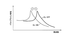
 図10は、前記駆動装置10において、前記クラッチCLの係合状態に応じて動力伝達系の共振周波数が異なることを模式的に説明する図である。図11は、前記クラッチCLの係合状態に応じた動力伝達系の特性(共振周波数)の変化を説明する図であり、前記クラッチCLが解放された状態における特性を実線で、前記クラッチCLが係合された状態における特性を破線でそれぞれ示している。前記駆動装置10において、前記ブレーキBKが解放された状態を考えると、前記クラッチCLの係合乃至解放に応じて前記駆動装置10における共振点(共振周波数)が変更される。すなわち、図10の上段に示すように前記クラッチCLが解放された状態においては、前記エンジン12と第1電動機MG1との間の動力伝達に係る動力伝達系に前記第2電動機MG2は連結されていない。その状態から下段に示すように前記クラッチCLが係合された状態へ切り換えられた場合、前記エンジン12と第1電動機MG1との間の動力伝達に係る動力伝達系に前記第2電動機MG2が連結され、その第2電動機MG2のロータ24等を含む構成が動力伝達系に加わるため、図11に示すように、慣性に係る特性(イナーシャバランス)が変化してその動力伝達系の共振点が変更される。特に、前記クラッチCLの係合状態の変化により、図10に示すように、前記エンジン12と前記第1電動機MG1を含む構成との間に設けられたダンパ62まわり(ダンパメイン)の構成に関する共振点が変更される。 FIG. 10 is a diagram schematically illustrating that in the driving device 10, the resonance frequency of the power transmission system varies depending on the engagement state of the clutch CL. FIG. 11 is a diagram for explaining a change in the characteristic (resonance frequency) of the power transmission system according to the engagement state of the clutch CL. The characteristic when the clutch CL is released is indicated by a solid line. The characteristics in the engaged state are indicated by broken lines, respectively. Considering a state in which the brake BK is released in the drive device 10, a resonance point (resonance frequency) in the drive device 10 is changed according to engagement or release of the clutch CL. That is, as shown in the upper stage of FIG. 10, in a state where the clutch CL is released, the second electric motor MG2 is connected to a power transmission system related to power transmission between the engine 12 and the first electric motor MG1. Absent. When the state is switched from the state to the state where the clutch CL is engaged as shown in the lower stage, the second electric motor MG2 is connected to the power transmission system related to the power transmission between the engine 12 and the first electric motor MG1. Since the configuration including the rotor 24 and the like of the second electric motor MG2 is added to the power transmission system, as shown in FIG. 11, the inertia characteristic (inertia balance) changes and the resonance point of the power transmission system changes. Is done. In particular, due to a change in the engagement state of the clutch CL, as shown in FIG. 10, resonance related to the configuration around the damper 62 (damper main) provided between the engine 12 and the configuration including the first electric motor MG1. The point is changed.
 図12は、前記駆動装置10において、前記クラッチCL及びブレーキBKの少なくとも一方の係合状態に応じて動力伝達系の共振周波数が異なることを模式的に説明する図である。図13は、前記クラッチCL及びブレーキBKの係合状態に応じた動力伝達系の特性(共振周波数)の変化を説明する図であり、前記クラッチCLが解放されると共に前記ブレーキBKが係合された状態における特性を実線で、前記クラッチCLが係合されると共に前記ブレーキBKが解放された状態における特性を破線でそれぞれ示している。図12及び図13においては、特に、前記第2電動機MG2のトルクが零付近(略零)である状態におけるダンパメインの特性を説明している。図12及び図13に示すように、前記駆動装置10においては、前記クラッチCLの係合状態の変更に加えて、或いはその代替として前記ブレーキBKの係合状態を変更することによっても前記駆動装置10における共振点(共振周波数)が変更される。すなわち、図12の上段に示すように前記クラッチCLが解放されると共に前記ブレーキBKが係合された状態すなわち図3に示すモード3(HV-1)等が成立している状態では、前記エンジン12と第1電動機MG1との間の動力伝達に係る動力伝達系に前記第2電動機MG2は連結されていない。一方、図12の下段に示すように前記クラッチCLが係合されると共に前記ブレーキBKが解放された状態すなわち図3に示すモード4(HV-2)等が成立している状態では、前記エンジン12と第1電動機MG1との間の動力伝達に係る動力伝達系に前記第2電動機MG2が連結される。すなわち、前記第2電動機MG2が入力側の動力伝達系に接続される。従って、図13に示すように、慣性に係る特性(イナーシャバランス)が変化してダンパメインの動力伝達系の共振点が変更される。 FIG. 12 is a diagram schematically illustrating that the resonance frequency of the power transmission system varies depending on the engagement state of at least one of the clutch CL and the brake BK in the driving device 10. FIG. 13 is a diagram for explaining a change in the characteristic (resonance frequency) of the power transmission system according to the engagement state of the clutch CL and the brake BK. The clutch CL is released and the brake BK is engaged. The characteristic in a state where the brake is engaged is indicated by a solid line, and the characteristic in a state where the clutch CL is engaged and the brake BK is released is indicated by a broken line. FIGS. 12 and 13 particularly explain the characteristics of the damper main in a state where the torque of the second electric motor MG2 is near zero (substantially zero). As shown in FIGS. 12 and 13, in the drive device 10, the drive device 10 is also changed by changing the engagement state of the brake BK in addition to or in place of changing the engagement state of the clutch CL. The resonance point (resonance frequency) at 10 is changed. That is, in the state where the clutch CL is released and the brake BK is engaged as shown in the upper part of FIG. 12, that is, in the state where the mode 3 (HV-1) shown in FIG. The second motor MG2 is not connected to a power transmission system related to power transmission between the motor 12 and the first motor MG1. On the other hand, in the state where the clutch CL is engaged and the brake BK is released as shown in the lower part of FIG. 12, that is, in the state where the mode 4 (HV-2) shown in FIG. The second electric motor MG2 is coupled to a power transmission system related to power transmission between the motor 12 and the first electric motor MG1. That is, the second electric motor MG2 is connected to the power transmission system on the input side. Therefore, as shown in FIG. 13, the inertia characteristic (inertia balance) changes to change the resonance point of the power transmission system of the damper main.
 図14及び図15は、前記エンジン12の動作点に対応して共振による騒音が発生する領域を例示する図であり、図14は前記クラッチCLが解放された状態における関係を、図15は前記クラッチCLが係合された状態における関係をそれぞれ示している。これら図14及び図15においては、前記エンジン12の回転に伴い発生する変動として、エンジン爆発1次成分(エンジン爆発に起因して1周期毎に発生する変動)による騒音が発生するNG領域をドット範囲で、エンジン回転0.5次成分(エンジン回転に起因して1/2周期毎に発生する変動)による騒音が発生するNG領域を左上から右下への斜線範囲でそれぞれ示している。図14及び図15においては、ダンパメインの共振周波数(共振点)を破線で示すと共に、前記エンジン12の最適燃費ラインを実線で併せて示している。この最適燃費ラインは、等燃費率曲線のうちの最も低い燃費領域をエンジン回転速度NEの上昇に伴って通過するように形成された予め実験的に求められた最適燃費点を結ぶ曲線である。この最適燃費率曲線は、運転性と燃費性とを両立するように予め実験的に設定されて前記エンジン12の最低燃費動作点を表す点の連なりでもある。 14 and 15 are diagrams illustrating a region where noise due to resonance occurs corresponding to the operating point of the engine 12, FIG. 14 shows a relationship in a state where the clutch CL is released, and FIG. The relationship in a state where the clutch CL is engaged is shown. In these FIGS. 14 and 15, NG regions where noise due to primary components of engine explosion (variations generated every cycle due to engine explosion) are generated as fluctuations generated as the engine 12 rotates are represented by dots. In the range, NG regions where noise due to the 0.5th-order component of engine rotation (variation occurring every 1/2 cycle due to engine rotation) is generated are indicated by hatched ranges from upper left to lower right. 14 and 15, the damper main resonance frequency (resonance point) is indicated by a broken line, and the optimum fuel consumption line of the engine 12 is also indicated by a solid line. The optimal fuel consumption line is the lowest fuel consumption region connecting the optimum fuel consumption point previously determined experimentally formed so as to pass with increasing engine rotational speed N E curves of equal fuel consumption curve . This optimum fuel efficiency rate curve is also a series of points that are experimentally set in advance so as to achieve both drivability and fuel efficiency and represent the minimum fuel efficiency operating point of the engine 12.
 図14及び図15に示すように、前記エンジン12の回転に伴い発生する変動のうち、斜線範囲で示すエンジン回転0.5次成分による騒音が発生するNG領域は、前記クラッチCLの係合状態を切り替えることにより移動する。すなわち、図14に示す関係では、斜線範囲で示すエンジン回転0.5次成分による騒音が発生するNG領域が、比較的エンジン回転速度が高い側(高回転速度側)に寄っているため、ドット範囲で示すエンジン爆発1次成分による騒音が発生するNG領域との重複範囲が狭く、ゆえに前記エンジン12の回転に伴い発生する変動に起因する騒音の発生が問題とならないOK領域が狭くなっている。ここで、前記駆動装置10におけるドライブラインの特性上、前記エンジン12と第1電動機MG1との間の動力伝達に係る動力伝達系に前記第2電動機MG2の慣性が加わることで、ダンパメインの共振周波数(共振点)が低周波側に移動する。従って、前記クラッチCLを係合させることで、図14に示す関係と比較して、図15に示すように斜線範囲で示すエンジン回転0.5次成分による騒音が発生するNG領域が比較的エンジン回転速度が低い側(低回転速度側)に移動する。これにより、ドット範囲で示すエンジン爆発1次成分による騒音が発生するNG領域との重複範囲が広くなり、ゆえに前記エンジン12の回転に伴い発生する変動に起因する騒音の発生が問題とならないOK領域が広くなる。すなわち、より好適な前記エンジン12の動作点をとることが可能となり、燃費を向上させることができる。 As shown in FIG. 14 and FIG. 15, among the fluctuations that occur with the rotation of the engine 12, the NG region where the noise due to the engine rotation 0.5th order component indicated by the hatched area is generated is the engagement state of the clutch CL. Move by switching. That is, in the relationship shown in FIG. 14, the NG region where the noise due to the engine rotation 0.5th order component indicated by the hatched area is on the relatively high engine rotation speed side (high rotation speed side). The overlapping range with the NG region where noise due to the primary component of the engine explosion shown in the range is generated is narrow, and therefore the OK region where the generation of noise due to fluctuations caused by the rotation of the engine 12 is not a problem is narrowed. . Here, due to the characteristics of the drive line in the drive device 10, the inertia of the second electric motor MG2 is added to the power transmission system related to the power transmission between the engine 12 and the first electric motor MG1, thereby resonating the damper main. The frequency (resonance point) moves to the low frequency side. Accordingly, when the clutch CL is engaged, the NG region in which noise due to the engine rotation 0.5th order component indicated by the hatched range is generated is relatively relatively engine-free as shown in FIG. 15 as compared with the relationship shown in FIG. Move to the low rotation speed side (low rotation speed side). As a result, the overlapping range with the NG region where the noise due to the engine explosion primary component indicated by the dot range is widened, and therefore, the OK region where the generation of noise due to fluctuations caused by the rotation of the engine 12 is not a problem. Becomes wider. That is, it is possible to take a more preferable operating point of the engine 12 and improve fuel efficiency.
 一方、図14及び図15を用いて説明した構成とは逆に、前記駆動装置10の設計等によっては、前記クラッチCLが係合している状態において、エンジン回転0.5次成分による騒音が発生するNG領域が、比較的エンジン回転速度が低い側(低回転速度側)に寄り過ぎ、エンジン爆発1次成分による騒音が発生するNG領域との重複範囲が狭く、ゆえに前記エンジン12の回転に伴い発生する変動に起因する騒音の発生が問題とならないOK領域が狭くなる場合が考えられる。斯かる場合においては、前記クラッチCLを解放させることで、エンジン回転0.5次成分による騒音が発生するNG領域が比較的エンジン回転速度が高い側(高回転速度側)に移動する。これにより、エンジン爆発1次成分による騒音が発生するNG領域との重複範囲が広くなり、ゆえに前記エンジン12の回転に伴い発生する変動に起因する騒音の発生が問題とならないOK領域が広くなる。すなわち、より好適な前記エンジン12の動作点をとることが可能となり、燃費を向上させることができる。 On the other hand, contrary to the configuration described with reference to FIGS. 14 and 15, depending on the design of the drive device 10, noise due to the engine rotation 0.5th order component may be generated when the clutch CL is engaged. The generated NG region is too close to the relatively low engine rotation speed (low rotation speed side), and the overlapping range with the NG region in which noise due to the primary component of the engine explosion is generated is narrow. It is conceivable that the OK region where the generation of noise due to the accompanying fluctuations does not matter becomes narrow. In such a case, by releasing the clutch CL, the NG region where noise due to the 0.5th-order component of the engine rotation is generated moves to a relatively high engine rotation speed side (high rotation speed side). As a result, the overlapping range with the NG region where noise due to the primary component of the engine explosion is generated is widened. Therefore, the OK region where the generation of noise due to fluctuations caused by the rotation of the engine 12 is not a problem is widened. That is, it is possible to take a more preferable operating point of the engine 12 and improve fuel efficiency.
 以上のような前記駆動装置10の性質を前提として、図9に示す共振点変更制御部84は、前記エンジン負荷運転判定部70及びMG2トルク判定部72の判定が共に肯定される場合、すなわち前記エンジン12の負荷運転中において、前記第2電動機MG2のトルクが零を含む規定の微小範囲内となる場合には、前記クラッチCLの係合状態を切り替える制御を行う。好適には、前記エンジン12の負荷運転中において、前記第2電動機MG2のトルクが零を含む規定の微小範囲内となる場合には、前記クラッチCLを係合させる制御を行う。図12~図15等を用いて説明したように、前記駆動装置10においては、前記クラッチCLの係合状態が切り替えられることにより、動力伝達系におけるダンパメインの共振周波数(共振点)が変更される。従って、前記共振点変更制御部84は、具体的には、前記動力伝達系における共振点を変更する制御として、前記油圧制御回路60を介して前記クラッチCLの係合状態を切り替える制御を行う。例えば、前記モード1(HV-1)の成立が判定されている場合等、前記クラッチCLが解放される走行モードが成立させられる場合であっても、前記エンジン12の負荷運転中であり且つ前記第2電動機MG2のトルクが零を含む規定の微小範囲内となる場合には、前記クラッチCLを係合させる制御を行う。 On the premise of the properties of the drive device 10 as described above, the resonance point change control unit 84 shown in FIG. 9 is when the determinations of the engine load operation determination unit 70 and the MG2 torque determination unit 72 are both affirmative, that is, During the load operation of the engine 12, when the torque of the second electric motor MG2 falls within a specified minute range including zero, control for switching the engagement state of the clutch CL is performed. Preferably, during the load operation of the engine 12, when the torque of the second electric motor MG2 is within a specified minute range including zero, control for engaging the clutch CL is performed. As described with reference to FIGS. 12 to 15 and the like, in the driving device 10, the resonance frequency (resonance point) of the damper main in the power transmission system is changed by switching the engagement state of the clutch CL. The Therefore, specifically, the resonance point change control unit 84 performs control for switching the engagement state of the clutch CL via the hydraulic control circuit 60 as control for changing the resonance point in the power transmission system. For example, even when the traveling mode in which the clutch CL is released is established, such as when it is determined that the mode 1 (HV-1) is established, the engine 12 is in a load operation and the When the torque of the second electric motor MG2 is within a specified minute range including zero, control for engaging the clutch CL is performed.
 前記共振点変更制御部84は、好適には、前記エンジン負荷運転判定部70、MG2トルク判定部72、及び共振判定部74の判定が何れも肯定される場合、すなわち前記エンジン12の負荷運転中において、前記第2電動機MG2のトルクが零を含む規定の微小範囲内であり且つ共振の発生が検出乃至予測される場合には、前記クラッチCLの係合状態を切り替える制御を行う。好適には、前記エンジン負荷運転判定部70及びMG2トルク判定部72の判定が共に肯定され、且つ前記変動入力判定部76、低温判定部78、EGR作動判定部80、及び触媒暖機判定部82のうち少なくとも1つの判定が肯定される場合には、前記クラッチCLの係合状態を切り替える制御を行う。好適には、前記エンジン12の負荷運転中において、前記第2電動機MG2のトルクが零を含む規定の微小範囲内であり且つ共振の発生が検出乃至予測される場合には、前記クラッチCLを係合させる制御を行う。 The resonance point change control unit 84 is preferably used when the determinations of the engine load operation determination unit 70, the MG2 torque determination unit 72, and the resonance determination unit 74 are all affirmative, that is, during load operation of the engine 12. When the torque of the second electric motor MG2 is within a specified minute range including zero and the occurrence of resonance is detected or predicted, control for switching the engagement state of the clutch CL is performed. Preferably, the determinations of the engine load operation determination unit 70 and the MG2 torque determination unit 72 are both affirmed, and the fluctuation input determination unit 76, the low temperature determination unit 78, the EGR operation determination unit 80, and the catalyst warm-up determination unit 82. If at least one of the determinations is affirmative, control for switching the engagement state of the clutch CL is performed. Preferably, during the load operation of the engine 12, when the torque of the second electric motor MG2 is within a specified minute range including zero and occurrence of resonance is detected or predicted, the clutch CL is engaged. Control to match.
 前記共振点変更制御部84は、好適には、前記駆動装置10が「D」レンジである場合、すなわち前記シフトセンサ54により検出されるシフトポジションが走行位置に相当する場合において、前記エンジン負荷運転判定部70、MG2トルク判定部72、及び共振判定部74の判定に基づく前記制御を行う。前記駆動装置10においては、前記エンジン12の負荷運転中であり且つEGRが作動している場合等において、前記第2電動機MG2のトルクが零付近すなわち零を含む規定の微小範囲内となる場合には、前記エンジン12の爆発1次成分による騒音(ガラ音)が発生する状態において更にそのエンジン12の回転0.5次成分が発生するおそれがある。特に、斯かるエンジン回転0.5次成分の周波数が動力伝達系におけるダンパメインの共振点と一致した場合、前記爆発1次成分を回避するためのライン(例えば、図14における二点鎖線に相当)よりも更に高エンジン回転速度且つ低エンジントルク側のライン(例えば、図14における一点鎖線に相当)を使用しなければ騒音の発生を回避できず、燃費の悪化に繋がるという弊害があった。本実施例によれば、前記エンジン12の負荷運転中において、前記第2電動機MG2のトルクが零を含む規定の微小範囲内となる場合には、前記クラッチCLの係合状態を切り替える制御を行うことで、例えば図14に示す関係から図15に示す関係へドライブラインの特性が変更される。これにより、騒音や振動の発生し易いNG領域が減少し、従来よりも好適な前記エンジン12の動作点をとることが可能となり、燃費を向上させることができる。 Preferably, the resonance point change control unit 84 performs the engine load operation when the drive device 10 is in the “D” range, that is, when the shift position detected by the shift sensor 54 corresponds to a travel position. The control based on the determinations of the determination unit 70, the MG2 torque determination unit 72, and the resonance determination unit 74 is performed. In the drive device 10, when the torque of the second electric motor MG <b> 2 is near zero, i.e., within a specified minute range including zero, when the engine 12 is under load operation and EGR is operating. In the state in which noise (rattle noise) due to the primary explosion component of the engine 12 is generated, there is a risk that a 0.5th-order component of rotation of the engine 12 is further generated. In particular, when the frequency of the engine rotation 0.5th order component coincides with the resonance point of the damper main in the power transmission system, a line for avoiding the explosion primary component (e.g., corresponding to the two-dot chain line in FIG. 14). If the line at the higher engine speed and the lower engine torque side (for example, corresponding to the alternate long and short dash line in FIG. 14) is not used, the generation of noise cannot be avoided, leading to a deterioration in fuel consumption. According to the present embodiment, during the load operation of the engine 12, when the torque of the second electric motor MG2 falls within a specified minute range including zero, control is performed to switch the engagement state of the clutch CL. Thus, for example, the characteristics of the drive line are changed from the relationship shown in FIG. 14 to the relationship shown in FIG. As a result, the NG region in which noise and vibration are likely to occur is reduced, and it becomes possible to take the operating point of the engine 12 that is more suitable than the conventional one, thereby improving the fuel consumption.
 前記共振点変更制御部84は、好適には、前記駆動装置10が「P」レンジである場合、すなわち前記シフトセンサ54により検出されるシフトポジションが停車位置に相当する場合において、前記エンジン負荷運転判定部70及び共振判定部74の判定に基づいて、前記駆動装置10における動力伝達系の共振点を変更する制御を行う。前記駆動装置10が適用されるハイブリッド車両が「P」レンジである停車中(車両停止時)において、冷間時負荷運転や触媒コンバータの暖機等が行われている場合には、前記エンジン12の駆動に伴うエンジン回転0.5次成分が発生し易い状態となる。斯かる状態においては、前記クラッチCLの係合状態を切り替える制御を行うこと、好適には前記クラッチCLを係合させる制御を行うことで、前記エンジン12の変動周波数から比較的離れた共振点を有するドライブライン特性を使用することができ、騒音や振動の発生を好適に抑制することができる。 Preferably, the resonance point change control unit 84 performs the engine load operation when the driving device 10 is in the “P” range, that is, when the shift position detected by the shift sensor 54 corresponds to a stop position. Based on the determination of the determination unit 70 and the resonance determination unit 74, control is performed to change the resonance point of the power transmission system in the drive device 10. When the hybrid vehicle to which the drive device 10 is applied is stopped (when the vehicle is stopped) in the “P” range, when the cold load operation or the warming-up of the catalytic converter is performed, the engine 12 Therefore, the engine rotation 0.5 order component is easily generated. In such a state, by performing control to switch the engagement state of the clutch CL, preferably by performing control to engage the clutch CL, a resonance point relatively far from the fluctuation frequency of the engine 12 is set. It is possible to use the driveline characteristics of the present invention, and it is possible to suitably suppress the generation of noise and vibration.
 図16は、前記電子制御装置40による共振点変更制御の要部を説明するフローチャートであり、所定の周期で繰り返し実行されるものである。 FIG. 16 is a flowchart for explaining a main part of the resonance point change control by the electronic control unit 40, which is repeatedly executed at a predetermined cycle.
 先ず、ステップ(以下、ステップを省略する)S1において、前記エンジン12が負荷運転を行っているか否かが判断される。このS1の判断が否定される場合には、それをもって本ルーチンが終了させられるが、S1の判断が肯定される場合には、S2において、前記第2電動機MG2のトルクが零付近すなわち零を含む規定の微小範囲内であるか否かが判断される。このS2の判断が否定される場合には、それをもって本ルーチンが終了させられるが、S2の判断が肯定される場合には、S3において、冷間負荷運転中やEGR作動時等、動力伝達系に共振を発生させる所定周波数が生じ易い状態であるか否かが判断される。このS3の判断が否定される場合には、それをもって本ルーチンが終了させられるが、S3の判断が肯定される場合には、S4において、前記クラッチCLの係合状態が切り替えられ、好適にはそのクラッチCLが係合させられた後、本ルーチンが終了させられる。以上の制御において、S1が前記エンジン負荷運転判定部70の動作に、S2が前記MG2トルク判定部72の動作に、S3が前記共振判定部74の動作に、S4が前記共振点変更制御部84の動作にそれぞれ対応する。 First, in step (hereinafter, step is omitted) S1, it is determined whether or not the engine 12 is performing a load operation. If the determination in S1 is negative, the routine is terminated accordingly. If the determination in S1 is affirmative, in S2, the torque of the second electric motor MG2 includes near zero, that is, includes zero. It is determined whether or not it is within a specified minute range. If the determination in S2 is negative, the routine is terminated accordingly, but if the determination in S2 is affirmative, in S3, during the cold load operation or EGR operation, the power transmission system It is determined whether or not a predetermined frequency for generating resonance is likely to occur. If the determination in S3 is negative, the routine is terminated accordingly, but if the determination in S3 is affirmative, the engagement state of the clutch CL is switched in S4, and preferably After the clutch CL is engaged, this routine is terminated. In the above control, S1 is the operation of the engine load operation determination unit 70, S2 is the operation of the MG2 torque determination unit 72, S3 is the operation of the resonance determination unit 74, and S4 is the resonance point change control unit 84. Correspond to each of the operations.
 図17は、前記電子制御装置40による共振点変更制御の他の一例の要部を説明するフローチャートであり、所定の周期で繰り返し実行されるものである。この図17に示す制御において、前述した図16に示す制御と同様のステップについては、同一の符号を付してその説明を省略する。図17の制御では、前記S1の判断が肯定される場合、すなわち前記エンジン12が負荷運転を行っていると判断される場合に、前記S3以下の処理が実行される。 FIG. 17 is a flowchart for explaining a main part of another example of the resonance point change control by the electronic control unit 40, which is repeatedly executed at a predetermined cycle. In the control shown in FIG. 17, the same steps as the control shown in FIG. 16 described above are denoted by the same reference numerals and description thereof is omitted. In the control of FIG. 17, when the determination of S1 is affirmed, that is, when it is determined that the engine 12 is performing load operation, the processing after S3 is executed.
 続いて、本発明の他の好適な実施例を図面に基づいて詳細に説明する。以下の説明において、実施例相互に共通する部分については同一の符号を付してその説明を省略する。 Subsequently, another preferred embodiment of the present invention will be described in detail with reference to the drawings. In the following description, parts common to the embodiments are denoted by the same reference numerals and description thereof is omitted.
 図18は、本発明が好適に適用される他のハイブリッド車両用駆動装置100(以下、単に駆動装置100という)の構成を説明する骨子図である。この図18に示す駆動装置100では、前記中心軸CEの軸方向に関して、前記第2遊星歯車装置16、クラッチCL、及びブレーキBKが、前記第2電動機MG2を間に挟んで、前記第1遊星歯車装置14に対して前記エンジン12の反対側に配置されている。前記クラッチCL及びブレーキBKは、好適には、前記中心軸CEの軸方向に関して略同じ位置に設けられている。すなわち、前記駆動装置100においては、前記中心軸CEの軸方向において、前記エンジン12側から前記第1電動機MG1、第1遊星歯車装置14、第2電動機MG2、第2遊星歯車装置16、クラッチCL及びブレーキBKの順でそれらの構成が同軸上に配置されている。斯かる構成の駆動装置100にも、本発明のハイブリッド車両の駆動制御装置は好適に適用される。 FIG. 18 is a skeleton diagram illustrating the configuration of another hybrid vehicle drive device 100 (hereinafter simply referred to as drive device 100) to which the present invention is preferably applied. In the drive device 100 shown in FIG. 18, with respect to the axial direction of the central axis CE, the second planetary gear device 16, the clutch CL, and the brake BK sandwich the second electric motor MG2 between the first planetary gears. The gear device 14 is disposed on the opposite side of the engine 12. The clutch CL and the brake BK are preferably provided at substantially the same position with respect to the axial direction of the central axis CE. That is, in the driving device 100, the first electric motor MG1, the first planetary gear device 14, the second electric motor MG2, the second planetary gear device 16, and the clutch CL from the engine 12 side in the axial direction of the central axis CE. And the structure is arrange | positioned coaxially in order of brake BK. The drive control device for a hybrid vehicle of the present invention is also suitably applied to the drive device 100 having such a configuration.
 図19は、本発明が好適に適用される更に別のハイブリッド車両用駆動装置110(以下、単に駆動装置110という)の構成を説明する骨子図である。この図19に示す駆動装置110では、前記中心軸CEの軸方向に関して、前記第1遊星歯車装置14、クラッチCL、第2遊星歯車装置16、及びブレーキBK等の構成すなわち機械系がまとめて前記エンジン12側に配置されると共に、それらの構成に対して前記第1電動機MG1及び第2電動機MG2等の構成すなわち電気系がまとめて前記エンジン12の反対側に配置されている。すなわち、前記駆動装置110においては、前記中心軸CEの軸方向において、前記エンジン12側から前記第1遊星歯車装置14、クラッチCL、第2遊星歯車装置16、ブレーキBK、第2電動機MG2、第1電動機MG1の順でそれらの構成が同軸上に配置されている。斯かる構成の駆動装置110にも、本発明のハイブリッド車両の駆動制御装置は好適に適用される。 FIG. 19 is a skeleton diagram illustrating the configuration of still another hybrid vehicle drive device 110 (hereinafter simply referred to as drive device 110) to which the present invention is preferably applied. In the drive device 110 shown in FIG. 19, the configuration of the first planetary gear device 14, the clutch CL, the second planetary gear device 16, the brake BK, etc., that is, the mechanical system is collectively related to the axial direction of the central axis CE. Arranged on the engine 12 side, the configurations of the first electric motor MG1 and the second electric motor MG2, etc., that is, the electrical system are collectively arranged on the opposite side of the engine 12 with respect to those configurations. That is, in the drive device 110, in the axial direction of the central axis CE, the first planetary gear device 14, the clutch CL, the second planetary gear device 16, the brake BK, the second electric motor MG2, Those components are arranged on the same axis in the order of one electric motor MG1. The drive control device for a hybrid vehicle of the present invention is also suitably applied to the drive device 110 having such a configuration.
 図20は、本発明が好適に適用される更に別のハイブリッド車両用駆動装置120(以下、単に駆動装置120という)の構成を説明する骨子図である。この図20に示す駆動装置120では、前記第2遊星歯車装置16のキャリアC2と非回転部材である前記ハウジング26との間に、そのキャリアC2のハウジング26に対する一方向の回転を許容し且つ逆方向の回転を阻止する一方向クラッチ(ワンウェイクラッチ)OWCが、前記ブレーキBKと並列に設けられている。この一方向クラッチOWCは、好適には、前記ハウジング26に対する前記キャリアC2の正方向の相対回転を許容する一方、負方向の回転を阻止する。すなわち、例えば前記第2電動機MG2により負トルクを出力させる場合等、前記キャリアC2が負方向に回転させられる駆動状態においては、前記ブレーキBKを係合させることなく前記モード1~3を成立させることができる。斯かる構成の駆動装置120にも、本発明のハイブリッド車両の駆動制御装置は好適に適用される。 FIG. 20 is a skeleton diagram illustrating the configuration of still another hybrid vehicle drive device 120 (hereinafter simply referred to as drive device 120) to which the present invention is preferably applied. In the driving device 120 shown in FIG. 20, the carrier C2 is allowed to rotate in one direction with respect to the housing 26 between the carrier C2 of the second planetary gear device 16 and the housing 26 which is a non-rotating member, and reversely. A one-way clutch (one-way clutch) OWC that prevents rotation in the direction is provided in parallel with the brake BK. The one-way clutch OWC preferably allows relative rotation of the carrier C2 in the positive direction with respect to the housing 26, while preventing rotation in the negative direction. That is, in the driving state in which the carrier C2 is rotated in the negative direction, for example, when the second electric motor MG2 outputs negative torque, the modes 1 to 3 are established without engaging the brake BK. Can do. The drive control device for a hybrid vehicle of the present invention is also suitably applied to the drive device 120 having such a configuration.
 図21は、本発明が好適に適用される更に別のハイブリッド車両用駆動装置130(以下、単に駆動装置130という)の構成を説明する骨子図である。この図21に示す駆動装置130は、前記シングルピニオン型の第2遊星歯車装置16の代替として、第2差動機構としてのダブルピニオン型の第2遊星歯車装置16′を前記中心軸CE上に備えている。この第2遊星歯車装置16′は、第1回転要素としてのサンギヤS2′、相互に噛み合わされた複数のピニオンギヤP2′を自転及び公転可能に支持する第2回転要素としてのキャリアC2′、及びピニオンギヤP2′を介してサンギヤS2′と噛み合う第3回転要素としてのリングギヤR2′を回転要素(要素)として備えている。 FIG. 21 is a skeleton diagram illustrating the configuration of still another hybrid vehicle drive device 130 (hereinafter simply referred to as drive device 130) to which the present invention is preferably applied. The drive device 130 shown in FIG. 21 has a double pinion type second planetary gear device 16 ′ as a second differential mechanism on the central axis CE as an alternative to the single pinion type second planetary gear device 16. I have. The second planetary gear unit 16 'includes a sun gear S2' as a first rotation element, a carrier C2 'as a second rotation element that supports a plurality of pinion gears P2' meshed with each other so as to rotate and revolve, and a pinion gear. A ring gear R2 ′ as a third rotating element that meshes with the sun gear S2 ′ via P2 ′ is provided as a rotating element (element).
 前記第1遊星歯車装置14のリングギヤR1は、出力回転部材である出力歯車30に連結されると共に、前記第2遊星歯車装置16′のキャリアC2′と相互に連結されている。前記第2遊星歯車装置16′のサンギヤS2′は、前記第2電動機MG2のロータ24に連結されている。前記第1遊星歯車装置14のキャリアC1と前記第2遊星歯車装置16′のリングギヤR2′との間には、それらキャリアC1とリングギヤR2′との間を選択的に係合させる(キャリアC1とリングギヤR2′との間を断接する)前記クラッチCLが設けられている。前記第2遊星歯車装置16′のリングギヤR2′と非回転部材である前記ハウジング26との間には、そのハウジング26に対して前記リングギヤR2′を選択的に係合(固定)させる前記ブレーキBKが設けられている。 The ring gear R1 of the first planetary gear device 14 is connected to an output gear 30 that is an output rotating member, and is also connected to a carrier C2 'of the second planetary gear device 16'. The sun gear S2 'of the second planetary gear device 16' is connected to the rotor 24 of the second electric motor MG2. The carrier C1 of the first planetary gear unit 14 and the ring gear R2 'of the second planetary gear unit 16' are selectively engaged between the carrier C1 and the ring gear R2 '(with the carrier C1). The clutch CL is provided to connect and disconnect the ring gear R2 ′. The brake BK for selectively engaging (fixing) the ring gear R2 'with the housing 26 between the ring gear R2' of the second planetary gear device 16 'and the housing 26 which is a non-rotating member. Is provided.
 図21に示すように、前記駆動装置130において、前記第1遊星歯車装置14及び第2遊星歯車装置16′は、それぞれ前記入力軸28と同軸上に配置されており、且つ、前記中心軸CEの軸方向において対向する位置に配置されている。すなわち、前記中心軸CEの軸方向に関して、前記第1遊星歯車装置14は、前記第2遊星歯車装置16′よりも前記エンジン12側に配置されている。前記中心軸CEの軸方向に関して、前記第1電動機MG1は、前記第1遊星歯車装置14よりも前記エンジン12側に配置されている。前記中心軸CEの軸方向に関して、前記第2電動機MG2は、前記第2遊星歯車装置16′に対して前記エンジン12の反対側に配置されている。すなわち、前記第1電動機MG1、第2電動機MG2は、前記中心軸CEの軸方向に関して、前記第1遊星歯車装置14及び第2遊星歯車装置16′を間に挟んで対向する位置に配置されている。すなわち、前記駆動装置130においては、前記中心軸CEの軸方向において、前記エンジン12側から前記第1電動機MG1、第1遊星歯車装置14、クラッチCL、第2遊星歯車装置16′、第2電動機MG2、ブレーキBKの順でそれらの構成が同軸上に配置されている。斯かる構成の駆動装置130にも、本発明のハイブリッド車両の駆動制御装置は好適に適用される。 As shown in FIG. 21, in the drive device 130, the first planetary gear device 14 and the second planetary gear device 16 'are arranged coaxially with the input shaft 28, respectively, and the central axis CE It arrange | positions in the position which opposes in the axial direction. That is, with respect to the axial direction of the central axis CE, the first planetary gear unit 14 is disposed closer to the engine 12 than the second planetary gear unit 16 ′. With respect to the axial direction of the central axis CE, the first electric motor MG1 is disposed closer to the engine 12 than the first planetary gear unit 14. With respect to the axial direction of the central axis CE, the second electric motor MG2 is disposed on the opposite side of the engine 12 with respect to the second planetary gear unit 16 ′. That is, the first electric motor MG1 and the second electric motor MG2 are arranged at positions facing each other with the first planetary gear device 14 and the second planetary gear device 16 ′ interposed therebetween with respect to the axial direction of the central axis CE. Yes. That is, in the drive device 130, the first electric motor MG1, the first planetary gear device 14, the clutch CL, the second planetary gear device 16 ', and the second electric motor are arranged from the engine 12 side in the axial direction of the central axis CE. These components are arranged on the same axis in the order of MG2 and brake BK. The drive control device for a hybrid vehicle of the present invention is also suitably applied to the drive device 130 having such a configuration.
 図22は、本発明が好適に適用される更に別のハイブリッド車両用駆動装置140(以下、単に駆動装置140という)の構成を説明する骨子図である。この図22に示す駆動装置140では、前記中心軸CEの軸方向に関して、前記第2遊星歯車装置16′、クラッチCL、及びブレーキBKが、前記第2電動機MG2を間に挟んで、前記第1遊星歯車装置14に対して前記エンジン12の反対側に配置されている。前記クラッチCL及びブレーキBKは、好適には、前記中心軸CEの軸方向に関して略同じ位置に設けられている。すなわち、前記駆動装置140においては、前記中心軸CEの軸方向において、前記エンジン12側から前記第1電動機MG1、第1遊星歯車装置14、第2電動機MG2、第2遊星歯車装置16′、クラッチCL及びブレーキBKの順でそれらの構成が同軸上に配置されている。斯かる構成の駆動装置140にも、本発明のハイブリッド車両の駆動制御装置は好適に適用される。 FIG. 22 is a skeleton diagram illustrating the configuration of still another hybrid vehicle drive device 140 (hereinafter simply referred to as drive device 140) to which the present invention is preferably applied. In the drive device 140 shown in FIG. 22, with respect to the axial direction of the central axis CE, the second planetary gear device 16 ′, the clutch CL, and the brake BK sandwich the second electric motor MG2 therebetween, and The planetary gear unit 14 is disposed on the opposite side of the engine 12. The clutch CL and the brake BK are preferably provided at substantially the same position with respect to the axial direction of the central axis CE. That is, in the driving device 140, the first electric motor MG1, the first planetary gear device 14, the second electric motor MG2, the second planetary gear device 16 ′, the clutch from the engine 12 side in the axial direction of the central axis CE. These components are arranged coaxially in the order of CL and brake BK. The drive control device for a hybrid vehicle of the present invention is also suitably applied to the drive device 140 having such a configuration.
 図23は、本発明が好適に適用される更に別のハイブリッド車両用駆動装置150(以下、単に駆動装置150という)の構成を説明する骨子図である。この図23に示す駆動装置150では、前記中心軸CEの軸方向に関して、前記第1電動機MG1及び第2電動機MG2等の構成すなわち電気系がまとめて前記エンジン12側に配置されると共に、それらの構成に対して前記第2遊星歯車装置16′、第1遊星歯車装置14、クラッチCL、及びブレーキBK等の構成すなわち機械系がまとめて前記エンジン12の反対側に配置されている。前記クラッチCL及びブレーキBKは、好適には、前記中心軸CEの軸方向に関して略同じ位置に設けられている。すなわち、前記駆動装置150においては、前記中心軸CEの軸方向において、前記エンジン12側から前記第1電動機MG1、第2電動機MG2、第2遊星歯車装置16′、第1遊星歯車装置14、クラッチCL及びブレーキBKの順でそれらの構成が同軸上に配置されている。斯かる構成の駆動装置150にも、本発明のハイブリッド車両の駆動制御装置は好適に適用される。 FIG. 23 is a skeleton diagram illustrating the configuration of still another hybrid vehicle drive device 150 (hereinafter simply referred to as drive device 150) to which the present invention is preferably applied. In the driving device 150 shown in FIG. 23, the configurations of the first electric motor MG1 and the second electric motor MG2, that is, the electric system are collectively arranged on the engine 12 side with respect to the axial direction of the central axis CE. The configuration of the second planetary gear device 16 ′, the first planetary gear device 14, the clutch CL, the brake BK, etc., that is, the mechanical system is collectively arranged on the opposite side of the engine 12 with respect to the configuration. The clutch CL and the brake BK are preferably provided at substantially the same position with respect to the axial direction of the central axis CE. That is, in the drive device 150, the first electric motor MG1, the second electric motor MG2, the second planetary gear device 16 ′, the first planetary gear device 14, the clutch in the axial direction of the central axis CE from the engine 12 side. These components are arranged coaxially in the order of CL and brake BK. The drive control device for a hybrid vehicle of the present invention is also suitably applied to the drive device 150 having such a configuration.
 図24~図26は、前記駆動装置10の代替として、本発明が好適に適用される他のハイブリッド車両用駆動装置160、170、180の構成及び作動をそれぞれ説明する共線図である。図24~図26では、前述した図4~7等の共線図と同様に、前記第1遊星歯車装置14におけるサンギヤS1、キャリアC1、リングギヤR1の相対的な回転速度を実線L1で、前記第2遊星歯車装置16におけるサンギヤS2、キャリアC2、リングギヤR2の相対的な回転速度を破線L2でそれぞれ示している。図24に示すハイブリッド車両用駆動装置160では、前記第1遊星歯車装置14のサンギヤS1、キャリアC1、及びリングギヤR1は、前記第1電動機MG1、前記エンジン12、及び前記第2電動機MG2にそれぞれ連結されている。前記第2遊星歯車装置16のサンギヤS2、キャリアC2、及びリングギヤR2は、前記第2電動機MG2、前記出力歯車30、及び前記ブレーキBKを介して前記ハウジング26にそれぞれ連結されている。前記サンギヤS1とリングギヤR2とが前記クラッチCLを介して選択的に連結されている。前記リングギヤR1とサンギヤS2とが相互に連結されている。図25に示すハイブリッド車両用駆動装置170では、前記第1遊星歯車装置14のサンギヤS1、キャリアC1、及びリングギヤR1は、前記第1電動機MG1、前記出力歯車30、及び前記エンジン12にそれぞれ連結されている。前記第2遊星歯車装置16のサンギヤS2、キャリアC2、及びリングギヤR2は、前記第2電動機MG2、前記出力歯車30、及び前記ブレーキBKを介して前記ハウジング26にそれぞれ連結されている。前記サンギヤS1と前記リングギヤR2とが前記クラッチCLを介して選択的に連結されている。前記クラッチC1及びC2が相互に連結されている。図26に示すハイブリッド車両用駆動装置180では、前記第1遊星歯車装置14のサンギヤS1、キャリアC1、及びリングギヤR1は、前記第1電動機MG1、前記出力歯車30、及び前記エンジン12にそれぞれ連結されている。前記第2遊星歯車装置16のサンギヤS2、キャリアC2、及びリングギヤR2は、前記第2電動機MG2、前記ブレーキBKを介して前記ハウジング26、及び前記出力歯車30にそれぞれ連結されている。前記リングギヤR1とキャリアC2とがクラッチCLを介して選択的に連結されている。前記キャリアC1とリングギヤR2とが相互に連結されている。 FIGS. 24 to 26 are collinear diagrams illustrating the configuration and operation of other hybrid vehicle drive devices 160, 170, and 180 to which the present invention is preferably applied as an alternative to the drive device 10. FIG. 24 to 26, similarly to the collinear charts of FIGS. 4 to 7 and the like described above, the relative rotational speeds of the sun gear S1, the carrier C1, and the ring gear R1 in the first planetary gear device 14 are indicated by the solid line L1. The relative rotational speeds of the sun gear S2, the carrier C2, and the ring gear R2 in the second planetary gear device 16 are indicated by broken lines L2. In the hybrid vehicle drive device 160 shown in FIG. 24, the sun gear S1, the carrier C1, and the ring gear R1 of the first planetary gear device 14 are coupled to the first electric motor MG1, the engine 12, and the second electric motor MG2, respectively. Has been. The sun gear S2, the carrier C2, and the ring gear R2 of the second planetary gear device 16 are connected to the housing 26 via the second electric motor MG2, the output gear 30, and the brake BK, respectively. The sun gear S1 and the ring gear R2 are selectively connected via the clutch CL. The ring gear R1 and the sun gear S2 are connected to each other. In the hybrid vehicle drive device 170 shown in FIG. 25, the sun gear S1, the carrier C1, and the ring gear R1 of the first planetary gear device 14 are connected to the first electric motor MG1, the output gear 30, and the engine 12, respectively. ing. The sun gear S2, the carrier C2, and the ring gear R2 of the second planetary gear device 16 are connected to the housing 26 via the second electric motor MG2, the output gear 30, and the brake BK, respectively. The sun gear S1 and the ring gear R2 are selectively connected via the clutch CL. The clutches C1 and C2 are connected to each other. In the hybrid vehicle drive device 180 shown in FIG. 26, the sun gear S1, the carrier C1, and the ring gear R1 of the first planetary gear device 14 are connected to the first electric motor MG1, the output gear 30, and the engine 12, respectively. ing. The sun gear S2, the carrier C2, and the ring gear R2 of the second planetary gear device 16 are connected to the housing 26 and the output gear 30 through the second electric motor MG2 and the brake BK, respectively. The ring gear R1 and the carrier C2 are selectively connected via a clutch CL. The carrier C1 and the ring gear R2 are connected to each other.
 図24~図26に示す実施例では、前述した図4~7等に示す実施例と同様に、共線図上において4つの回転要素を有する(4つの回転要素として表現される)第1差動機構としての第1遊星歯車装置14及び第2差動機構としての第2遊星歯車装置16、16′と、それら4つの回転要素にそれぞれ連結された第1電動機MG1、第2電動機MG2、エンジン12、及び出力回転部材(出力歯車30)とを、備え、前記4つの回転要素のうちの1つは、前記第1遊星歯車装置14の回転要素と前記第2遊星歯車装置16、16′の回転要素とがクラッチCLを介して選択的に連結され、そのクラッチCLによる係合対象となる前記第2遊星歯車装置16、16′の回転要素が、非回転部材であるハウジング26に対してブレーキBKを介して選択的に連結されるハイブリッド車両の駆動制御装置である点で、共通している。すなわち、図9等を用いて前述した本発明のハイブリッド車両の駆動制御装置は、図24~図26に示す構成にも好適に適用される。 In the embodiment shown in FIGS. 24 to 26, the first difference having four rotation elements (expressed as four rotation elements) on the collinear chart is the same as the embodiment shown in FIGS. The first planetary gear unit 14 as the moving mechanism and the second planetary gear units 16 and 16 'as the second differential mechanism, and the first electric motor MG1, the second electric motor MG2, and the engine connected to the four rotating elements, respectively. 12 and an output rotation member (output gear 30), one of the four rotation elements being the rotation element of the first planetary gear device 14 and the second planetary gear device 16, 16 '. A rotating element is selectively connected via a clutch CL, and the rotating element of the second planetary gear devices 16 and 16 'to be engaged by the clutch CL is braked against the housing 26 which is a non-rotating member. Via BK In that it is a drive control apparatus for a hybrid vehicle which is selectively connected Te, it is common. That is, the hybrid vehicle drive control apparatus of the present invention described above with reference to FIG. 9 and the like is also preferably applied to the configurations shown in FIGS.
 このように、本実施例によれば、クラッチCLが係合された状態において全体として4つの回転要素を有する(図4~図7等に示す共線図上において4つの回転要素として表される)第1差動機構である第1遊星歯車装置14及び第2差動機構である第2遊星歯車装置16、16′と、それら4つの回転要素にそれぞれ連結されたエンジン12、第1電動機MG1、第2電動機MG2、及び出力回転部材である出力歯車30とを、備え、前記4つの回転要素のうちの1つは、前記第1差動機構の回転要素と前記第2差動機構の回転要素とがクラッチCLを介して選択的に連結され、そのクラッチCLによる係合対象となる前記第1差動機構又は前記第2差動機構の回転要素が、非回転部材であるハウジング26に対してブレーキBKを介して選択的に連結されるハイブリッド車両の駆動制御装置であって、前記エンジン12の負荷運転中において、前記第2電動機MG2のトルクが零を含む規定の微小範囲内となる場合には、前記クラッチCLの係合状態を切り替えるものであることから、前記第2電動機トルクが零付近であり動力伝達系の共振が発生し易い場合に、動力伝達系のイナーシャバランスを変化させることで共振点を変更し、共振の発生を好適に抑制することができる。すなわち、動力伝達系の振動を抑制するハイブリッド車両の駆動制御装置としての電子制御装置40を提供することができる。 As described above, according to the present embodiment, there are four rotating elements as a whole in a state in which the clutch CL is engaged (represented as four rotating elements on the collinear chart shown in FIGS. 4 to 7 and the like). ) The first planetary gear unit 14 that is the first differential mechanism and the second planetary gear units 16 and 16 'that are the second differential mechanism, and the engine 12 and the first electric motor MG1 that are respectively connected to these four rotating elements. , A second electric motor MG2, and an output gear 30 that is an output rotation member, and one of the four rotation elements is a rotation element of the first differential mechanism and a rotation of the second differential mechanism. Are connected to each other through a clutch CL, and the rotating element of the first differential mechanism or the second differential mechanism to be engaged by the clutch CL is connected to the housing 26 which is a non-rotating member. Through the brake BK In the hybrid vehicle drive control apparatus that is selectively coupled, when the torque of the second electric motor MG2 is within a specified minute range including zero during the load operation of the engine 12, the clutch CL When the second motor torque is near zero and resonance of the power transmission system is likely to occur, the resonance point is changed by changing the inertia balance of the power transmission system. The occurrence of resonance can be suitably suppressed. That is, it is possible to provide the electronic control device 40 as a drive control device for a hybrid vehicle that suppresses vibration of the power transmission system.
 前記エンジン12の負荷運転中において、前記第2電動機MG2のトルクが零を含む規定の微小範囲内であり且つ共振の発生が検出乃至予測される場合には、前記クラッチCLの係合状態を切り替えるものであるため、前記第2電動機トルクが零付近である場合において動力伝達系の共振が検出乃至予測された場合に、動力伝達系のイナーシャバランスを変化させることで共振点を変更し、共振の発生を好適に抑制することができる。 During the load operation of the engine 12, when the torque of the second electric motor MG2 is within a specified minute range including zero and occurrence of resonance is detected or predicted, the engagement state of the clutch CL is switched. Therefore, when resonance of the power transmission system is detected or predicted when the second motor torque is near zero, the resonance point is changed by changing the inertia balance of the power transmission system, Generation | occurrence | production can be suppressed suitably.
 前記第1遊星歯車装置14は、前記第1電動機MG1に連結された第1回転要素としてのサンギヤS1、前記エンジン12に連結された第2回転要素としてのキャリアC1、及び前記出力歯車30に連結された第3回転要素としてのリングギヤR1を備え、前記第2遊星歯車装置16(16′)は、前記第2電動機MG2に連結された第1回転要素としてのサンギヤS2(S2′)、第2回転要素としてのキャリアC2(C2′)、及び第3回転要素としてのリングギヤR2(R2′)を備え、それらキャリアC2(C2′)及びリングギヤR2(R2′)の何れか一方が前記第1遊星歯車装置14のリングギヤR1に連結されたものであり、前記クラッチCLは、前記第1遊星歯車装置14におけるキャリアC1と、前記キャリアC2(C2′)及びリングギヤR2(R2′)のうち前記リングギヤR1に連結されていない方の回転要素とを選択的に係合させるものであり、前記ブレーキBKは、前記キャリアC2(C2′)及びリングギヤR2(R2′)のうち前記リングギヤR1に連結されていない方の回転要素を、非回転部材であるハウジング26に対して選択的に係合させるものであることから、実用的なハイブリッド車両の駆動装置10等において、動力伝達系の振動を抑制することができる。 The first planetary gear unit 14 is connected to a sun gear S1 as a first rotating element connected to the first electric motor MG1, a carrier C1 as a second rotating element connected to the engine 12, and the output gear 30. The second planetary gear unit 16 (16 ′) includes a sun gear S2 (S2 ′), a second rotation element connected to the second electric motor MG2, and a second gear R1. A carrier C2 (C2 ′) as a rotating element and a ring gear R2 (R2 ′) as a third rotating element are provided, and any one of the carrier C2 (C2 ′) and the ring gear R2 (R2 ′) is the first planet. The clutch CL is connected to the ring gear R1 of the gear device 14, and the clutch CL includes the carrier C1 in the first planetary gear device 14 and the carrier C2 ( 2 ′) and the ring gear R2 (R2 ′), which is selectively engaged with the rotating element not connected to the ring gear R1, the brake BK includes the carrier C2 (C2 ′) and the ring gear. R2 (R2 ′), which is not connected to the ring gear R1, is selectively engaged with the housing 26, which is a non-rotating member. In the device 10 or the like, vibration of the power transmission system can be suppressed.
 以上、本発明の好適な実施例を図面に基づいて詳細に説明したが、本発明はこれに限定されるものではなく、その趣旨を逸脱しない範囲内において種々の変更が加えられて実施されるものである。 The preferred embodiments of the present invention have been described in detail with reference to the drawings. However, the present invention is not limited to these embodiments, and various modifications can be made without departing from the spirit of the present invention. Is.
 10、100、110、120、130、140、150、160、170、180:ハイブリッド車両用駆動装置、12:エンジン、14:第1遊星歯車装置(第1差動機構)、16、16′:第2遊星歯車装置(第2差動機構)、18、22:ステータ、20、24:ロータ、26:ハウジング(非回転部材)、28:入力軸、30:出力歯車(出力回転部材)、32:オイルポンプ、34:EGRバルブ、40:電子制御装置(駆動制御装置)、42:アクセル開度センサ、44:エンジン回転速度センサ、46:MG1回転速度センサ、48:MG2回転速度センサ、50:出力回転速度センサ、52:油温センサ、54:シフトセンサ、56:エンジン制御装置、58:インバータ、60:油圧制御回路、62:ダンパ、64:ドライブシャフト、66:タイヤ、68:ボデー、70:エンジン負荷運転判定部、72:MG2トルク判定部、74:共振判定部、76:変動入力判定部、78:低温判定部、80:EGR作動判定部、82:触媒暖機判定部、84:共振点変更制御部、BK:ブレーキ、CL:クラッチ、C1、C2、C2′:キャリア(第2回転要素)、MG1:第1電動機、MG2:第2電動機、OWC:一方向クラッチ、P1、P2、P2′:ピニオンギヤ、R1、R2、R2′:リングギヤ(第3回転要素)、S1、S2、S2′:サンギヤ(第1回転要素) 10, 100, 110, 120, 130, 140, 150, 160, 170, 180: drive device for hybrid vehicle, 12: engine, 14: first planetary gear device (first differential mechanism), 16, 16 ′: Second planetary gear device (second differential mechanism), 18, 22: stator, 20, 24: rotor, 26: housing (non-rotating member), 28: input shaft, 30: output gear (output rotating member), 32 : Oil pump, 34: EGR valve, 40: electronic control device (drive control device), 42: accelerator opening sensor, 44: engine rotational speed sensor, 46: MG1 rotational speed sensor, 48: MG2 rotational speed sensor, 50: Output rotational speed sensor, 52: oil temperature sensor, 54: shift sensor, 56: engine control device, 58: inverter, 60: hydraulic control circuit, 62: damper, 64: Live shaft, 66: tire, 68: body, 70: engine load operation determination unit, 72: MG2 torque determination unit, 74: resonance determination unit, 76: fluctuation input determination unit, 78: low temperature determination unit, 80: EGR operation determination Part, 82: catalyst warm-up determination part, 84: resonance point change control part, BK: brake, CL: clutch, C1, C2, C2 ': carrier (second rotating element), MG1: first motor, MG2: first 2 motors, OWC: one-way clutch, P1, P2, P2 ': pinion gear, R1, R2, R2': ring gear (third rotating element), S1, S2, S2 ': sun gear (first rotating element)

Claims (3)

  1.  全体として4つの回転要素を有する第1差動機構及び第2差動機構と、該4つの回転要素にそれぞれ連結されたエンジン、第1電動機、第2電動機、及び出力回転部材とを、備え、
     前記4つの回転要素のうちの1つは、前記第1差動機構の回転要素と前記第2差動機構の回転要素とがクラッチを介して選択的に連結され、
     該クラッチによる係合対象となる前記第1差動機構又は前記第2差動機構の回転要素が、非回転部材に対してブレーキを介して選択的に連結される
     ハイブリッド車両の駆動制御装置であって、
     前記エンジンの負荷運転中において、前記第2電動機のトルクが零を含む規定の微小範囲内となる場合には、前記クラッチの係合状態を切り替えることを特徴とするハイブリッド車両の駆動制御装置。
    A first differential mechanism and a second differential mechanism having four rotation elements as a whole, and an engine, a first electric motor, a second electric motor, and an output rotation member respectively connected to the four rotation elements;
    In one of the four rotation elements, the rotation element of the first differential mechanism and the rotation element of the second differential mechanism are selectively connected via a clutch,
    A drive control device for a hybrid vehicle, wherein a rotating element of the first differential mechanism or the second differential mechanism to be engaged by the clutch is selectively connected to a non-rotating member via a brake. And
    A drive control apparatus for a hybrid vehicle, wherein the engagement state of the clutch is switched when the torque of the second electric motor falls within a specified minute range including zero during load operation of the engine.
  2.  前記エンジンの負荷運転中において、前記第2電動機のトルクが零を含む規定の微小範囲内であり且つ共振の発生が検出乃至予測される場合には、前記クラッチの係合状態を切り替えるものである請求項1に記載のハイブリッド車両の駆動制御装置。 During the engine load operation, when the torque of the second electric motor is within a specified minute range including zero and the occurrence of resonance is detected or predicted, the engagement state of the clutch is switched. The drive control apparatus of the hybrid vehicle of Claim 1.
  3.  前記第1差動機構は、前記第1電動機に連結された第1回転要素、前記エンジンに連結された第2回転要素、及び前記出力回転部材に連結された第3回転要素を備えたものであり、
     前記第2差動機構は、前記第2電動機に連結された第1回転要素、第2回転要素、及び第3回転要素を備え、それら第2回転要素及び第3回転要素の何れか一方が前記第1差動機構における第3回転要素に連結されたものであり、
     前記クラッチは、前記第1差動機構における第2回転要素と、前記第2差動機構における第2回転要素及び第3回転要素のうち前記第1差動機構における第3回転要素に連結されていない方の回転要素とを選択的に係合させるものであり、
     前記ブレーキは、前記第2差動機構における第2回転要素及び第3回転要素のうち前記第1差動機構における第3回転要素に連結されていない方の回転要素を、前記非回転部材に対して選択的に係合させるものである
     請求項1又は2に記載のハイブリッド車両の駆動制御装置。
    The first differential mechanism includes a first rotating element connected to the first electric motor, a second rotating element connected to the engine, and a third rotating element connected to the output rotating member. Yes,
    The second differential mechanism includes a first rotating element, a second rotating element, and a third rotating element connected to the second electric motor, and any one of the second rotating element and the third rotating element is the above-mentioned Connected to the third rotating element in the first differential mechanism,
    The clutch is coupled to a second rotating element in the first differential mechanism and a third rotating element in the first differential mechanism among the second rotating element and the third rotating element in the second differential mechanism. Which selectively engages the rotating element that is not present,
    The brake is configured such that, of the second rotating element and the third rotating element in the second differential mechanism, the rotating element that is not connected to the third rotating element in the first differential mechanism is connected to the non-rotating member. The hybrid vehicle drive control device according to claim 1, wherein the drive control device is selectively engaged.
PCT/JP2012/057809 2012-03-26 2012-03-26 Drive control device for hybrid vehicle WO2013145090A1 (en)

Priority Applications (4)

Application Number Priority Date Filing Date Title
US14/387,765 US20150087458A1 (en) 2012-03-26 2012-03-26 Drive control device for hybrid vehicle
CN201280071865.6A CN104220314A (en) 2012-03-26 2012-03-26 Drive control device for hybrid vehicle
PCT/JP2012/057809 WO2013145090A1 (en) 2012-03-26 2012-03-26 Drive control device for hybrid vehicle
EP12872877.1A EP2832614A1 (en) 2012-03-26 2012-03-26 Drive control device for hybrid vehicle

Applications Claiming Priority (1)

Application Number Priority Date Filing Date Title
PCT/JP2012/057809 WO2013145090A1 (en) 2012-03-26 2012-03-26 Drive control device for hybrid vehicle

Publications (1)

Publication Number Publication Date
WO2013145090A1 true WO2013145090A1 (en) 2013-10-03

Family

ID=49258460

Family Applications (1)

Application Number Title Priority Date Filing Date
PCT/JP2012/057809 WO2013145090A1 (en) 2012-03-26 2012-03-26 Drive control device for hybrid vehicle

Country Status (4)

Country Link
US (1) US20150087458A1 (en)
EP (1) EP2832614A1 (en)
CN (1) CN104220314A (en)
WO (1) WO2013145090A1 (en)

Cited By (2)

* Cited by examiner, † Cited by third party
Publication number Priority date Publication date Assignee Title
GB2504821A (en) * 2012-06-07 2014-02-12 Jaguar Land Rover Ltd A hybrid electric vehicle control system and corresponding method
JP2016132442A (en) * 2015-01-22 2016-07-25 スズキ株式会社 Vehicle damping controller

Families Citing this family (4)

* Cited by examiner, † Cited by third party
Publication number Priority date Publication date Assignee Title
CN103998309B (en) * 2011-12-19 2016-10-12 丰田自动车株式会社 Motor vehicle driven by mixed power drive dynamic control device
JP6531946B2 (en) * 2015-10-09 2019-06-19 日立オートモティブシステムズ株式会社 Control device of electric vehicle, control system of electric vehicle, and control method of electric vehicle
JP6798972B2 (en) * 2017-12-26 2020-12-09 本田技研工業株式会社 Vehicle with rotary electric machine
JP7310731B2 (en) * 2020-06-23 2023-07-19 トヨタ自動車株式会社 four wheel drive vehicle

Citations (4)

* Cited by examiner, † Cited by third party
Publication number Priority date Publication date Assignee Title
JP2005199942A (en) * 2004-01-19 2005-07-28 Toyota Motor Corp Power output device, automobile with the power output device mounted thereon, and power transmission
JP2006077859A (en) * 2004-09-08 2006-03-23 Nissan Motor Co Ltd Drive mechanism for hybrid vehicle
JP2007232069A (en) * 2006-02-28 2007-09-13 Toyota Motor Corp Controller for power transmitting device for vehicle
JP2008265600A (en) 2007-04-23 2008-11-06 Toyota Motor Corp Vehicle and control method thereof

Family Cites Families (5)

* Cited by examiner, † Cited by third party
Publication number Priority date Publication date Assignee Title
CA2259771C (en) * 1998-02-19 2003-04-01 Hitachi, Ltd. Transmission, and vehicle and bicycle using the same
JP2000094973A (en) * 1998-09-28 2000-04-04 Hitachi Ltd Transmission and hybrid vehicle using it
JP3402236B2 (en) * 1999-01-13 2003-05-06 トヨタ自動車株式会社 Power output device, hybrid vehicle, and control method therefor
JP3585916B1 (en) * 2003-06-12 2004-11-10 本田技研工業株式会社 Power transmission device of hybrid vehicle
JP4358264B2 (en) * 2007-08-08 2009-11-04 株式会社日本自動車部品総合研究所 Hybrid vehicle

Patent Citations (4)

* Cited by examiner, † Cited by third party
Publication number Priority date Publication date Assignee Title
JP2005199942A (en) * 2004-01-19 2005-07-28 Toyota Motor Corp Power output device, automobile with the power output device mounted thereon, and power transmission
JP2006077859A (en) * 2004-09-08 2006-03-23 Nissan Motor Co Ltd Drive mechanism for hybrid vehicle
JP2007232069A (en) * 2006-02-28 2007-09-13 Toyota Motor Corp Controller for power transmitting device for vehicle
JP2008265600A (en) 2007-04-23 2008-11-06 Toyota Motor Corp Vehicle and control method thereof

Cited By (3)

* Cited by examiner, † Cited by third party
Publication number Priority date Publication date Assignee Title
GB2504821A (en) * 2012-06-07 2014-02-12 Jaguar Land Rover Ltd A hybrid electric vehicle control system and corresponding method
GB2504821B (en) * 2012-06-07 2015-02-18 Jaguar Land Rover Ltd Hybrid electric vehicle control system and method
JP2016132442A (en) * 2015-01-22 2016-07-25 スズキ株式会社 Vehicle damping controller

Also Published As

Publication number Publication date
CN104220314A (en) 2014-12-17
EP2832614A1 (en) 2015-02-04
US20150087458A1 (en) 2015-03-26

Similar Documents

Publication Publication Date Title
WO2013088501A1 (en) Drive control device for hybrid vehicle
JP5967105B2 (en) Drive control apparatus for hybrid vehicle
JP5846219B2 (en) Drive control apparatus for hybrid vehicle
JP6114255B2 (en) Drive control apparatus for hybrid vehicle
JP5874812B2 (en) Drive control apparatus for hybrid vehicle
WO2013140537A1 (en) Drive control device for hybrid vehicle
JP5884897B2 (en) Drive control apparatus for hybrid vehicle
WO2013145093A1 (en) Hybrid vehicle drive control device
JP5971330B2 (en) Drive control apparatus for hybrid vehicle
WO2013140546A1 (en) Drive control device for hybrid vehicle
WO2013145100A1 (en) Drive control device for a hybrid vehicle
JP6024740B2 (en) Drive control apparatus for hybrid vehicle
JP2015174555A (en) Control device for hybrid vehicle driving device
JP5874813B2 (en) Drive control apparatus for hybrid vehicle
WO2013145089A1 (en) Drive control device for hybrid vehicle
WO2013145090A1 (en) Drive control device for hybrid vehicle
WO2013140542A1 (en) Drive control device for hybrid vehicle
JP6011560B2 (en) Control device for drive device for hybrid vehicle
WO2013140545A1 (en) Drive control device for hybrid vehicle
JP2013203388A (en) Drive controller of hybrid vehicle
JP2013203386A (en) Drive controller of hybrid vehicle
WO2013145091A1 (en) Hybrid vehicle drive control device
JP5924402B2 (en) Drive control apparatus for hybrid vehicle
WO2013145098A1 (en) Hybrid vehicle drive control device
JP2013203385A (en) Drive control device for hybrid vehicle

Legal Events

Date Code Title Description
121 Ep: the epo has been informed by wipo that ep was designated in this application

Ref document number: 12872877

Country of ref document: EP

Kind code of ref document: A1

ENP Entry into the national phase

Ref document number: 2014507061

Country of ref document: JP

Kind code of ref document: A

WWE Wipo information: entry into national phase

Ref document number: 14387765

Country of ref document: US

NENP Non-entry into the national phase

Ref country code: DE

WWE Wipo information: entry into national phase

Ref document number: 2012872877

Country of ref document: EP