JP6199552B2 - High pressure gas tank inspection method - Google Patents
High pressure gas tank inspection method Download PDFInfo
- Publication number
- JP6199552B2 JP6199552B2 JP2012234982A JP2012234982A JP6199552B2 JP 6199552 B2 JP6199552 B2 JP 6199552B2 JP 2012234982 A JP2012234982 A JP 2012234982A JP 2012234982 A JP2012234982 A JP 2012234982A JP 6199552 B2 JP6199552 B2 JP 6199552B2
- Authority
- JP
- Japan
- Prior art keywords
- gas
- tank
- resin layer
- reinforced resin
- pressure
- Prior art date
- Legal status (The legal status is an assumption and is not a legal conclusion. Google has not performed a legal analysis and makes no representation as to the accuracy of the status listed.)
- Expired - Fee Related
Links
Images

Classifications
-
- Y—GENERAL TAGGING OF NEW TECHNOLOGICAL DEVELOPMENTS; GENERAL TAGGING OF CROSS-SECTIONAL TECHNOLOGIES SPANNING OVER SEVERAL SECTIONS OF THE IPC; TECHNICAL SUBJECTS COVERED BY FORMER USPC CROSS-REFERENCE ART COLLECTIONS [XRACs] AND DIGESTS
- Y02—TECHNOLOGIES OR APPLICATIONS FOR MITIGATION OR ADAPTATION AGAINST CLIMATE CHANGE
- Y02E—REDUCTION OF GREENHOUSE GAS [GHG] EMISSIONS, RELATED TO ENERGY GENERATION, TRANSMISSION OR DISTRIBUTION
- Y02E60/00—Enabling technologies; Technologies with a potential or indirect contribution to GHG emissions mitigation
- Y02E60/30—Hydrogen technology
- Y02E60/32—Hydrogen storage
Landscapes
- Filling Or Discharging Of Gas Storage Vessels (AREA)
- Pressure Vessels And Lids Thereof (AREA)
Description
本発明は、タンクライナの外周に繊維強化樹脂層を形成してなる高圧ガスタンクの検査方法に関する。 The present invention relates to an inspection method for a high-pressure gas tank in which a fiber reinforced resin layer is formed on the outer periphery of a tank liner.
例えば燃料電池自動車や水素自動車に搭載される水素ガスタンク等、高圧のガスが内部に充填される高圧ガスタンクには、内部の圧力に耐えるために十分な強度を有することが求められる。このような高圧ガスタンクとしては、樹脂等により形成されたタンクライナの外周に繊維強化樹脂層を形成したものが用いられている。 For example, high-pressure gas tanks filled with high-pressure gas such as hydrogen gas tanks mounted on fuel cell vehicles and hydrogen vehicles are required to have sufficient strength to withstand the internal pressure. As such a high-pressure gas tank, a tank in which a fiber reinforced resin layer is formed on the outer periphery of a tank liner formed of resin or the like is used.
高圧ガスタンクが十分な強度を有するかどうかを検査する方法の一つとしては、製造された高圧ガスタンクの一部を抜き取って破壊検査を行うことが考えられる。このような破壊検査は、例えば高圧ガスタンクの内部気圧を上昇させて行き、高圧ガスタンクが破損した時点における内部気圧が所定の閾値よりも大きいか否かに基づいて合否判定を行うものである。 One method for inspecting whether the high-pressure gas tank has sufficient strength is to extract a part of the manufactured high-pressure gas tank and perform a destructive inspection. In such destructive inspection, for example, the internal pressure of the high-pressure gas tank is increased, and pass / fail judgment is performed based on whether or not the internal pressure at the time when the high-pressure gas tank is damaged is larger than a predetermined threshold value.
また、下記特許文献1には、高圧ガスタンクの内部を高圧とした状態で、繊維強化樹脂層の損傷に基づく応力変化をピエゾ素子で検出するという検査方法が記載されている。
製造された高圧ガスタンクの一部を抜き取って破壊検査を行う場合には、全ての高圧ガスタンクが十分な強度を有することを保証することができない。また、上記特許文献1に記載されているような検査方法では、ピエゾ素子の設置個所によっては繊維強化樹脂層の損傷を検知することができない場合がある。
When a part of the manufactured high-pressure gas tank is extracted and subjected to destructive inspection, it cannot be guaranteed that all the high-pressure gas tanks have sufficient strength. Further, in the inspection method described in
また、繊維強化樹脂層のガス透過度が低すぎると、タンクライナを透過したガスがタンクライナと繊維強化樹脂層との間に留まって高圧となり、当該ガスが繊維強化樹脂層の一部を破壊して外部に漏出し、破裂音が生じてしまうことがある。このため、繊維強化樹脂層は十分な強度を有することが求められる一方で、ある程度のガス透過度を有することも求められる。しかしながら、上記特許文献1に記載されているような検査方法では、繊維強化樹脂層のガス透過度が適切か否かについて判断することができない。
If the gas permeability of the fiber reinforced resin layer is too low, the gas that has permeated the tank liner stays between the tank liner and the fiber reinforced resin layer, resulting in a high pressure, and the gas destroys part of the fiber reinforced resin layer. Then, it may leak out and make a popping sound. For this reason, while a fiber reinforced resin layer is calculated | required to have sufficient intensity | strength, it is also calculated | required to have a certain amount of gas permeability. However, it is impossible to determine whether or not the gas permeability of the fiber reinforced resin layer is appropriate by the inspection method described in
本発明はこのような課題に鑑みてなされたものであり、その目的は、繊維強化樹脂層の全体が十分な強度を有するかどうかを非破壊で検査することができ、繊維強化樹脂層のガス透過度が適切かどうかについても検査することができる高圧ガスタンクの検査方法を提供することにある。 The present invention has been made in view of such problems, and its purpose is to be able to non-destructively inspect whether or not the entire fiber reinforced resin layer has sufficient strength. An object of the present invention is to provide an inspection method for a high-pressure gas tank that can inspect whether or not the permeability is appropriate.
上記課題を解決するために、本発明に係る高圧ガスタンクの検査方法は、タンクライナの外周に繊維強化樹脂層を形成してなる高圧ガスタンクの検査方法であって、前記高圧ガスタンクに検知ガスを封入するステップと、前記高圧ガスタンクから単位時間あたりに漏出する前記検知ガスの漏出量を測定するステップと、測定された前記漏出量に基づいて前記繊維強化樹脂層のガス透過度を算出するステップと、前記ガス透過度が所定範囲内にあるかどうかに基づいて合否を判定するステップと、を有することを特徴としている。 In order to solve the above-described problems, a high-pressure gas tank inspection method according to the present invention is a high-pressure gas tank inspection method in which a fiber reinforced resin layer is formed on the outer periphery of a tank liner, and a detection gas is sealed in the high-pressure gas tank. Measuring a leakage amount of the detection gas leaked from the high-pressure gas tank per unit time, calculating a gas permeability of the fiber reinforced resin layer based on the measured leakage amount, Determining whether the gas permeability is within a predetermined range or not.
本発明に係る高圧ガスタンクの検査方法は、高圧ガスタンクに検知ガスを封入しておき、高圧ガスタンクから単位時間あたりに漏出する検知ガスの漏出量に基づいて、繊維強化樹脂層のガス透過度を算出する。算出されたガス透過度が所定範囲内にある場合には合格と判定する。換言すれば、繊維強化樹脂層のガス透過度が所定範囲の上限を上回った場合には、繊維強化樹脂層の強度が不十分であると推定されるために不合格と判定する。一方、所定範囲の下限を下回った場合には、破裂音が生じてしまう可能性があると推定されるため、やはり不合格と判定する。 The method for inspecting a high-pressure gas tank according to the present invention encloses a detection gas in the high-pressure gas tank, and calculates the gas permeability of the fiber reinforced resin layer based on the amount of detection gas leaked from the high-pressure gas tank per unit time. To do. When the calculated gas permeability is within a predetermined range, it is determined as acceptable. In other words, when the gas permeability of the fiber reinforced resin layer exceeds the upper limit of the predetermined range, it is determined that the fiber reinforced resin layer is not acceptable because the strength of the fiber reinforced resin layer is estimated to be insufficient. On the other hand, when the value falls below the lower limit of the predetermined range, it is estimated that a plosive sound may be generated.
本発明では、高圧ガスタンクから漏出する検知ガスの漏出量に基づいて繊維強化樹脂層のガス透過度を判定するため、高圧ガスタンクを破壊することなく、繊維強化樹脂層の全体について検査が行われる。 In the present invention, since the gas permeability of the fiber reinforced resin layer is determined based on the leakage amount of the detection gas leaking from the high pressure gas tank, the entire fiber reinforced resin layer is inspected without destroying the high pressure gas tank.
また、ガス透過度が所定範囲の上限を上回った場合に不合格と判定する他、所定範囲の下限を下回った場合にも不合格と判定する。すなわち、繊維強化樹脂層の全体の強度が不十分である場合のみならず、繊維強化樹脂層のガス透過度が低すぎて破裂音が生じてしまう可能性がある場合も不合格と判定する。このように、高圧ガスタンクの検査を従来よりも好適且つ確実に行うことができる。 Further, in addition to determining that the gas permeability exceeds the upper limit of the predetermined range, it is determined to be unacceptable. That is, not only when the overall strength of the fiber reinforced resin layer is insufficient, but also when the gas permeability of the fiber reinforced resin layer is too low and a plosive sound may be generated, it is determined as rejected. Thus, the inspection of the high-pressure gas tank can be performed more suitably and reliably than in the past.
本発明によれば、繊維強化樹脂層の全体が十分な強度を有するかどうかを非破壊で検査することができ、繊維強化樹脂層のガス透過度が適切かどうかについても検査することができる高圧ガスタンクの検査方法を提供することができる。 According to the present invention, it is possible to nondestructively inspect whether or not the entire fiber reinforced resin layer has sufficient strength, and it is possible to inspect whether or not the gas permeability of the fiber reinforced resin layer is appropriate. A gas tank inspection method can be provided.
以下、添付図面を参照しながら本発明の実施の形態について説明する。説明の理解を容易にするため、各図面において同一の構成要素に対しては可能な限り同一の符号を付して、重複する説明は省略する。 Hereinafter, embodiments of the present invention will be described with reference to the accompanying drawings. In order to facilitate the understanding of the description, the same constituent elements in the drawings will be denoted by the same reference numerals as much as possible, and redundant description will be omitted.
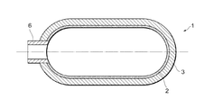
図1は、本発明の一実施形態に係る検査方法の検査対象である高圧ガスタンクの構造を示す断面図である。図1に示したように、高圧ガスタンク1は、タンクライナ2と、繊維強化樹脂層3と、口金6とを備えている。
FIG. 1 is a cross-sectional view showing the structure of a high-pressure gas tank that is an inspection target of an inspection method according to an embodiment of the present invention. As shown in FIG. 1, the high-
タンクライナ2は、高圧ガスタンク1のうち最も内側に配置されるものであって、高圧の水素ガスをその内部に保持できるように筒状を成す樹脂性の部材である。タンクライナ2の長手方向における一端部には口金6が取り付けられており、他端部は閉じられている。
The
口金6は、タンクライナ2の長手方向の一端部に取り付けられた略円筒形状の金属部品であって、タンクライナ2の開口部に嵌入されている。口金6は、高圧ガスタンク1内の水素ガスをタンク外に供給する際において、外部のガス供給ラインとの接続を行うために使用される。
The
繊維強化樹脂層3は、タンクライナ2の外周に繊維を巻きつけることによって形成される層である。具体的には、タンクライナ2の外周全体にカーボン繊維を巻き付けた後、当該カーボン繊維をエポキシ樹脂によりバインドすることで形成される層であり、所謂CFRP(Carbon Fiber Reinforced Prastics)と称されるものである。このような繊維強化樹脂層3をタンクライナ2の外側に形成することで、充填した高圧の水素ガスの圧力に対する高圧ガスタンク1の強度を向上させている。
The fiber reinforced resin layer 3 is a layer formed by winding fibers around the outer periphery of the
本実施形態に係る高圧ガスタンクの検査方法は、上記のような高圧ガスタンク1において繊維強化樹脂層3が十分な強度を有するかどうかを検査するものである。同時に、繊維強化樹脂層3のガス透過度が適切か否かを検査するものである。尚、ガス透過度については以下で詳しく説明する。
The inspection method for a high-pressure gas tank according to this embodiment is to inspect whether or not the fiber reinforced resin layer 3 has sufficient strength in the high-
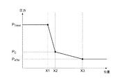
本実施形態に係る検査方法の説明に先立って、タンクライナ2及び繊維強化樹脂層3のガス透過度について図2を参照しながら説明する。図2は、高圧ガスタンク1の内外における圧力分布を示すグラフである。図2に示したグラフの横軸は、高圧ガスタンク1の内外における位置を、高圧ガスタンク1の中心軸(タンクライナ2の長手方向に沿った中心軸)からの距離により示している。位置X1はタンクライナ2の内周面の位置であり、位置X2はタンクライナ2の外周面の位置である(位置X2は、タンクライナ2と繊維強化樹脂層3の境界部分の位置であるともいえる)。また、位置X3は繊維強化樹脂層3の外周面の位置である。図2に示したグラフの縦軸は、それぞれの位置における気体の圧力を示している。
Prior to the description of the inspection method according to the present embodiment, the gas permeability of the
図2に示したように、位置X1よりも内側の部分(図2では左側の部分)はタンクライナ2の内側の空間であるから、当該部分の圧力は充填されたガスの圧力(PTANK)となっている。また、位置X3よりも外側の部分(図2では右側の部分)は高圧ガスタンク1の外側の空間であるから、当該部分の圧力は大気圧(PATM)となっている。
As shown in FIG. 2, the portion inside the position X1 (the portion on the left side in FIG. 2) is the space inside the
タンクライナ2の内部に充填された高圧のガスは、内外の圧力差に起因して、タンクライナ2を構成する樹脂の内部を透過して外部(位置X2)に漏出する。単位時間当たりの当該漏出量は微量ではあるが、当該漏出に伴って位置X2におけるガスの圧力(PC)は時間の経過とともに上昇する。
The high-pressure gas filled in the
同様に、位置X2における気体の圧力(PC)と位置X3における気体の圧力(PATM)との差に起因して、高圧ガスタンク1に充填されたガスは繊維強化樹脂層3の内部をも透過して外部(位置X3)に漏出する。このため、位置X2におけるガスの圧力(PC)は時間の経過とともに一定の圧力に落ち着き、高圧ガスタンク1の内外における圧力分布は図2に示したような分布となる。
Similarly, due to the difference between the gas pressure (P C ) at the
図2においては、グラフの傾きの絶対値の逆数が、当該部分におけるガス透過度(Gas Transmission Rate)の大きさを示している。ガス透過度とは、単位面積、単位時間、及び単位分圧差当りのガスの透過量である。 In FIG. 2, the reciprocal of the absolute value of the slope of the graph indicates the magnitude of the gas transmission rate in that portion. The gas permeability is a gas permeation amount per unit area, unit time, and unit partial pressure difference.
図2から明らかなように、定常状態におけるPCは、タンクライナ2のガス透過度GTR1が大きいほど(グラフの傾きが小さいほど)大きくなる。また、繊維強化樹脂層3のガス透過度GTR2が大きいほど(グラフの傾きが小さいほど)小さくなる。
As apparent from FIG. 2, P C in the steady state, as the gas permeability
仮に繊維強化樹脂層3の強度が低い場合には、繊維強化樹脂層3の亀裂量が多いため、繊維強化樹脂層3のガス透過度GTR2が大きくなってPCが小さくなる。逆に、繊維強化樹脂層3の強度が高い場合には、繊維強化樹脂層3の亀裂量が少ないため、繊維強化樹脂層3のガス透過度GTR2が小さくなってPCが大きくなる。 If when the intensity of the fiber reinforced resin layer 3 is low, since many cracking of the fiber reinforced resin layer 3, P C decreases gas permeability GTR2 of fiber-reinforced resin layer 3 is increased. Conversely, if the strength of the fiber reinforced resin layer 3 is high, since cracking of the fiber reinforced resin layer 3 is small, P C is increased gas permeability GTR2 of fiber-reinforced resin layer 3 is decreased.
このため、繊維強化樹脂層3の強度を十分なものとすることだけを考慮すれば、繊維強化樹脂層3のガス透過度GTR2をできるだけ小さくし、結果としてPCが大きくする程望ましいようにも思われる。しかし、PCが大きくなり過ぎてしまうと、位置X2において高圧となったガスが繊維強化樹脂層3の一部を破壊して外部に漏出し、破裂音が生じてしまうことがある。また、それに伴って繊維強化樹脂層3が白濁してしまうことがある。従って、繊維強化樹脂層3のガス透過度GTR2はできるだけ小さくするのではなく、所定の上限値と下限値との間に収めることが望ましい。 Therefore, considering only to the strength of the fiber reinforced resin layer 3 made sufficient to minimize the gas permeability GTR2 of fiber-reinforced resin layer 3, also as desired as P C is increased as a result Seem. However, if P C becomes too large, the gas becomes high pressure to leak out to destroy a portion of the fiber-reinforced resin layer 3 at the position X2, it may pop occurs. Moreover, the fiber reinforced resin layer 3 may become cloudy in connection with it. Therefore, it is desirable that the gas permeability GTR2 of the fiber reinforced resin layer 3 is not made as small as possible, but is set between a predetermined upper limit value and a lower limit value.
図3を参照しながら、本実施形態に係る検査方法を行うための検査装置について説明する。図3は、検査対象である高圧ガスタンク1を検査装置100にセットした状態を模式的に示す図である。図3に示したように、検査装置100は、チャンバーCHと、リークディテクタLDと、ヘリウム充填装置HFとを備えている。
An inspection apparatus for performing the inspection method according to the present embodiment will be described with reference to FIG. FIG. 3 is a diagram schematically showing a state in which the high-
チャンバーCHは、高圧ガスタンク1を内部に収納するための気密な容器である。チャンバーCHは、高圧ガスタンク1を出し入れするための図示しない開口部と、当該開口部を気密に塞いだ状態とする図示しない開閉機構を備えている。
The chamber CH is an airtight container for accommodating the high-
リークディテクタLDは、気体を吸引して当該気体に含まれるヘリウムガスの量を測定する装置であって、図3に示したようにバルブB1を介してチャンバーCHの内部空間と接続されている。バルブB1を開いた状態においてリークディテクタLDによる測定を開始すると、リークディテクタLDはチャンバーCHの内部から気体を吸引する。リークディテクタLDは、吸引した気体に含まれるヘリウムガスの量に基づいて、単位時間当たりのヘリウムガスの漏出量をリアルタイムに表示する。 The leak detector LD is a device that sucks gas and measures the amount of helium gas contained in the gas, and is connected to the internal space of the chamber CH via the valve B1 as shown in FIG. When measurement by the leak detector LD is started in a state where the valve B1 is opened, the leak detector LD sucks gas from the inside of the chamber CH. The leak detector LD displays the amount of helium gas leaked per unit time in real time based on the amount of helium gas contained in the sucked gas.
以上のような構成の検査装置100を用いて、高圧ガスタンク1の検査を行う方法について説明する。まず、検査対象である高圧ガスタンク1をチャンバーCHの内部にセットする。具体的には、チャンバーCHの開口部から高圧ガスタンク1を投入し、チャンバーCHの内部空間に高圧ガスタンク1を設置する。このとき、高圧ガスタンク1の口金6に対して、バルブB2を介してヘリウム充填装置HFを接続した状態としておく。また、バルブB1、B2はいずれも閉じた状態としておく。その後、チャンバーCHの開閉機構を操作し、開口部を気密に塞いだ状態とする。
A method for inspecting the high-
続いて、バルブB2を開いた状態でヘリウム充填装置HFを動作させることにより、高圧ガスタンク1の内部にヘリウムガスを充填し封入する。ヘリウムガスの充填は、高圧ガスタンク1の内部圧力が大気圧よりも高い所定の圧力となるまで行われる。ヘリウム充填装置HFによるヘリウムガスの充填が完了すると、バルブB2を閉じる。
Subsequently, by operating the helium filling device HF with the valve B2 opened, the inside of the high
続いて、バルブB1を開いてリークディテクタLDによる気体の吸引を開始する。リークディテクタLDは、吸引した気体に含まれるヘリウムガスの量に基づいて、単位時間当たりのヘリウムガスの漏出量QALLをリアルタイムに表示する。この漏出量QALLは、高圧ガスタンク1の内部からタンクライナ2及び繊維強化樹脂層3の内部を透過し、チャンバーCHの内部空間に単位時間当たりに漏出したヘリウムガスの量である。
Subsequently, the valve B1 is opened and gas suction by the leak detector LD is started. The leak detector LD displays the helium gas leakage amount Q ALL per unit time in real time based on the amount of helium gas contained in the sucked gas. This leakage amount Q ALL is the amount of helium gas that permeates through the
ヘリウム充填装置HFと口金6とを接続する配管等にはOリングが用いられている。当該Oリングを透過してチャンバーCH内に漏出するヘリウムガスの量(単位時間当たりの漏出量)をQOとし、タンクライナ2の外周部分における表面積をSLとし、繊維強化樹脂層3の外周部分における表面積をSCとし、タンクライナ2の厚さをDLとし、繊維強化樹脂層3の厚さをDCとすれば、漏出量QALLは、以下の2式で表すことができる。
QALL=QO+GTR1×SL×(PTANK−PC)×1/DL・・・(1)
GTR1×SL×(PTANK−PC)×1/DL=GTR2×SC×(PC−PATM)×1/DC・・・(2)
An O-ring is used for piping or the like that connects the helium filling device HF and the
Q ALL = Q O +
GTR1 × S L × (P TANK −P C ) × 1 / D L =
このうち、PTANK、PATM、SL、SC、DL、DCは既知の値である。また、GTR1及びQOは繊維強化樹脂層3の状態によらない値であり、高圧ガスタンク1毎に異なるものではないため、事前の測定等により予め求めておくことができる。従って、リークディテクタLDが表示した漏出量QALLを上記の式(1)及び式(2)に代入し、これらを連立させて解けば、未知の値であるGTR2及びPCを算出することができる。
Of these, P TANK , P ATM , S L , S C , D L , and D C are known values. Further, GTR1 and
以上のように、本実施形態に係る高圧ガスタンクの検査方法によれば、高圧ガスタンク1から単位時間あたりに漏出するヘリウムガスの漏出量QALLを測定し、当該漏出量QALLに基づいて繊維強化樹脂層3のガス透過度GTR2を算出する。
As described above, according to the inspection method for a high-pressure gas tank according to the present embodiment, the leakage amount Q ALL of helium gas leaking from the high-
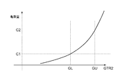
図4は、繊維強化樹脂層3のガス透過度GTR2と、繊維強化樹脂層3の亀裂量との関係を示すグラフである。図4に示したように、算出されたガス透過度GTR2が大きいほど、繊維強化樹脂層3の亀裂量が多い、すなわち、繊維強化樹脂層3の強度が低い。 FIG. 4 is a graph showing the relationship between the gas permeability GTR2 of the fiber reinforced resin layer 3 and the crack amount of the fiber reinforced resin layer 3. As shown in FIG. 4, as the calculated gas permeability GTR2 is larger, the amount of cracks in the fiber reinforced resin layer 3 is larger, that is, the strength of the fiber reinforced resin layer 3 is lower.
また、図4に示したC1は、繊維強化樹脂層3の亀裂量の許容下限値であって、亀裂量がこれを下回った場合には前述の破裂音や白濁が生じてしまう値である。図4に示したC2は、繊維強化樹脂層3の亀裂量の許容上限値であって、亀裂量がこれを上回った場合には繊維強化樹脂層3の強度が不十分なものとなってしまう値である。 Further, C1 shown in FIG. 4 is an allowable lower limit value of the crack amount of the fiber reinforced resin layer 3, and is a value at which the above-described plosive sound or white turbidity occurs when the crack amount is lower than this. C2 shown in FIG. 4 is an allowable upper limit value of the crack amount of the fiber reinforced resin layer 3, and if the crack amount exceeds this, the strength of the fiber reinforced resin layer 3 becomes insufficient. Value.
図4に示した関係に基づいて、C1に対応するガス透過度GTR2(ガス透過度GTR2の下限値GL)と、C2に対応するガス透過度GTR2(ガス透過度GTR2の上限値GU)とを予め実験等により求めておく。 Based on the relationship shown in FIG. 4, the gas permeability GTR2 (the lower limit value GL of the gas permeability GTR2) corresponding to C1 and the gas permeability GTR2 (the upper limit value GU of the gas permeability GTR2) corresponding to C2 are obtained. Obtained in advance by experiments or the like.
本実施形態においては、高圧ガスタンク1の使用時において充填されるガス(水素ガス)とは異なるガス(ヘリウムガス)を、検知ガスとして用いている。このため、検査に用いる上記下限値GL及び上限値GUは、このようなガス種の違いを考慮して予め求めておく必要がある。
In the present embodiment, a gas (helium gas) different from the gas (hydrogen gas) filled when the high-
尚、検知ガスとして用いることができるのはヘリウムガスに限られず、水素ガスを用いてもよい。この場合には、ヘリウム充填装置に替えて水素充填装置を用いる必要がある。また、ヘリウムガス用のリークディテクタLDに替えて、水素ガス用のリークディテクタを用いる必要がある。 In addition, what can be used as detection gas is not restricted to helium gas, You may use hydrogen gas. In this case, it is necessary to use a hydrogen filling device instead of the helium filling device. Further, it is necessary to use a leak detector for hydrogen gas instead of the leak detector LD for helium gas.
本実施形態に係る高圧ガスタンクの検査方法においては、漏出量QALLに基づいて算出されたガス透過度GTR2が、予め求めておいた下限値GLと上限値GUとで定まる所定範囲内にあるかどうかを判断し、当該判断に基づいて高圧ガスタンク1の合否を判定する。すなわち、算出されたガス透過度GTR2が下限値GLよりも小さければ、破裂音や白濁が生じる可能性があるために不合格と判定する。ガス透過度GTR2が上限値GUよりも大きければ、繊維強化樹脂層3の強度が不十分であるために不合格と判定する。ガス透過度GTR2が下限値GLと上限値GUとで定まる所定範囲内にあれば、合格と判定する。
In the high-pressure gas tank inspection method according to the present embodiment, is the gas permeability GTR2 calculated based on the leakage amount Q ALL within a predetermined range determined by the lower limit value GL and the upper limit value GU that are obtained in advance? Whether or not the high-
ところで、高圧の水素ガスを封入する高圧ガスタンクには、水素ガスの漏出量が所定値以下であることを確認するための気密試験を行うことが法令で定められている。このような気密試験は、図3を参照しながら説明したものと同様の方法により検知ガス(ヘリウムガス)の漏出量QALLを測定し、当該漏出量QALLが所定の閾値よりも小さいかどうかを確認する試験である。 By the way, it is stipulated by law that a high-pressure gas tank filled with high-pressure hydrogen gas should be subjected to an airtight test for confirming that the amount of hydrogen gas leaked is a predetermined value or less. In such an airtight test, the leak amount Q ALL of the detection gas (helium gas) is measured by the same method as described with reference to FIG. 3, and whether or not the leak amount Q ALL is smaller than a predetermined threshold value. It is a test to confirm.
すなわち、本実施形態に係る高圧ガスタンクの検査方法は、法令で実施が定められている気密試験を行うことにより漏出量QALLを測定するのと同時に、ガス透過度GTR2を算出してそれが適切な値であるか(下限値GLと上限値GUとで定まる所定範囲内にあるか)を確認することができる。換言すれば、充填されたガスの漏出量が所定値以下であることを確認するのと同時に、繊維強化樹脂層3の強度が適切か否かについても確認することができる。 That is, the high-pressure gas tank inspection method according to the present embodiment calculates the gas permeability GTR2 at the same time that the leak rate Q ALL is measured by performing an airtight test that is stipulated by law. Can be confirmed (whether it is within a predetermined range determined by the lower limit value GL and the upper limit value GU). In other words, it is possible to confirm whether or not the strength of the fiber reinforced resin layer 3 is appropriate at the same time as confirming that the amount of leakage of the filled gas is not more than a predetermined value.
以上、具体例を参照しつつ本発明の実施の形態について説明した。しかし、本発明はこれらの具体例に限定されるものではない。すなわち、これら具体例に、当業者が適宜設計変更を加えたものも、本発明の特徴を備えている限り、本発明の範囲に包含される。例えば、前述した各具体例が備える各要素およびその配置、材料、条件、形状、サイズなどは、例示したものに限定されるわけではなく適宜変更することができる。また、前述した各実施の形態が備える各要素は、技術的に可能な限りにおいて組み合わせることができ、これらを組み合わせたものも本発明の特徴を含む限り本発明の範囲に包含される。 The embodiments of the present invention have been described above with reference to specific examples. However, the present invention is not limited to these specific examples. In other words, those specific examples that have been appropriately modified by those skilled in the art are also included in the scope of the present invention as long as they have the characteristics of the present invention. For example, the elements included in each of the specific examples described above and their arrangement, materials, conditions, shapes, sizes, and the like are not limited to those illustrated, but can be changed as appropriate. Moreover, each element with which each embodiment mentioned above is provided can be combined as long as technically possible, and the combination of these is also included in the scope of the present invention as long as it includes the features of the present invention.
1:高圧ガスタンク
2:タンクライナ
3:繊維強化樹脂層
6:口金
100:検査装置
B1,B2:バルブ
CH:チャンバー
HF:ヘリウム充填装置
LD:リークディテクタ
1: High pressure gas tank 2: Tank liner 3: Fiber reinforced resin layer 6: Base 100: Inspection device B1, B2: Valve CH: Chamber HF: Helium filling device LD: Leak detector
Claims (1)
前記高圧ガスタンクに検知ガスを封入するステップと、
前記高圧ガスタンクから単位時間あたりに漏出する前記検知ガスの漏出量を、前記高圧ガスタンクの口金に接続されるOリングを透過して外部に漏出する前記検知ガスの量と、前記タンクライナ及び前記繊維強化樹脂層を透過する前記検知ガスの量とに基づき測定するステップと、
測定された前記漏出量に基づいて前記繊維強化樹脂層のガス透過度を算出するステップと、
前記ガス透過度が所定範囲内にあるかどうかに基づいて合否を判定するステップと、を有し、
前記検知ガスの漏出量Q ALL を、下記式(1)、(2);
Q ALL =Q O +GTR1×S L ×(P TANK −P C )×1/D L ・・・(1)
GTR1×S L ×(P TANK −P C )×1/D L =GTR2×S C ×(P C −P ATM )×1/D C ・・・(2)
Q O :前記高圧ガスタンクの口金に接続されるOリングを透過して外部に漏出するヘリウムガスの量、
S L :前記タンクライナの外周部分における表面積、
S C :前記繊維強化樹脂層の外周部分における表面積、
D L :前記タンクライナの厚さ、
D C :前記繊維強化樹脂層の厚さ、
P TANK :前記タンクライナ内に充填されたガスの圧力、
P C :前記タンクライナの外周面の位置におけるガスの圧力、
P ATM :前記繊維強化樹脂層の外周面の位置における気体の圧力、
GTR1:前記タンクライナのガス透過度、
GTR2:前記繊維強化樹脂層のガス透過度、
で表される関係に基づき測定することを特徴とする高圧ガスタンクの検査方法。 An inspection method for a high-pressure gas tank in which a fiber reinforced resin layer is formed on the outer periphery of a tank liner,
Enclosing a detection gas in the high-pressure gas tank;
The amount of the detection gas leaking from the high-pressure gas tank per unit time, the amount of the detection gas leaking outside through the O-ring connected to the base of the high-pressure gas tank, the tank liner and the fiber Measuring based on the amount of the detection gas that permeates the reinforced resin layer;
Calculating the gas permeability of the fiber reinforced resin layer based on the measured leakage amount;
Possess determining acceptability, the gas permeability on the basis of whether it is within a predetermined range,
The leakage amount Q ALL of the detection gas is expressed by the following formulas (1) and (2);
Q ALL = Q O + GTR 1 × S L × (P TANK −P C ) × 1 / D L (1)
GTR1 × S L × (P TANK −P C ) × 1 / D L = GTR 2 × S C × (P C −P ATM ) × 1 / D C (2)
Q O : the amount of helium gas that leaks outside through the O-ring connected to the base of the high-pressure gas tank,
S L : surface area of the outer periphery of the tank liner,
S C : surface area in the outer peripheral portion of the fiber reinforced resin layer,
D L : thickness of the tank liner,
D C : thickness of the fiber reinforced resin layer,
P TANK : Pressure of gas filled in the tank liner,
P C : gas pressure at the position of the outer peripheral surface of the tank liner,
P ATM : Gas pressure at the position of the outer peripheral surface of the fiber reinforced resin layer,
GTR1: Gas permeability of the tank liner,
GTR2: gas permeability of the fiber reinforced resin layer,
An inspection method for a high-pressure gas tank, characterized in that measurement is performed based on the relationship represented by
Priority Applications (1)
| Application Number | Priority Date | Filing Date | Title |
|---|---|---|---|
| JP2012234982A JP6199552B2 (en) | 2012-10-24 | 2012-10-24 | High pressure gas tank inspection method |
Applications Claiming Priority (1)
| Application Number | Priority Date | Filing Date | Title |
|---|---|---|---|
| JP2012234982A JP6199552B2 (en) | 2012-10-24 | 2012-10-24 | High pressure gas tank inspection method |
Publications (2)
| Publication Number | Publication Date |
|---|---|
| JP2014084957A JP2014084957A (en) | 2014-05-12 |
| JP6199552B2 true JP6199552B2 (en) | 2017-09-20 |
Family
ID=50788212
Family Applications (1)
| Application Number | Title | Priority Date | Filing Date |
|---|---|---|---|
| JP2012234982A Expired - Fee Related JP6199552B2 (en) | 2012-10-24 | 2012-10-24 | High pressure gas tank inspection method |
Country Status (1)
| Country | Link |
|---|---|
| JP (1) | JP6199552B2 (en) |
Families Citing this family (2)
| Publication number | Priority date | Publication date | Assignee | Title |
|---|---|---|---|---|
| JP6939525B2 (en) * | 2017-12-25 | 2021-09-22 | トヨタ自動車株式会社 | How to manufacture high pressure tank |
| US20210341106A1 (en) * | 2020-04-30 | 2021-11-04 | Entegris, Inc. | Regulator assembly and test method |
Family Cites Families (4)
| Publication number | Priority date | Publication date | Assignee | Title |
|---|---|---|---|---|
| JP2007085807A (en) * | 2005-09-21 | 2007-04-05 | Meiji Univ | Gas barrier property evaluation method of plastic bottle and container and apparatus used therefor |
| JP2009216133A (en) * | 2008-03-07 | 2009-09-24 | Toyota Motor Corp | Gas cylinder and gas exhaust hole formation method of the gas cylinder |
| JP2009222195A (en) * | 2008-03-18 | 2009-10-01 | Toyota Motor Corp | Method and device of manufacturing gas vessel and gas vessel |
| JP2010053981A (en) * | 2008-08-28 | 2010-03-11 | Toyota Motor Corp | Gas container manufacturing method and gas container |
-
2012
- 2012-10-24 JP JP2012234982A patent/JP6199552B2/en not_active Expired - Fee Related
Also Published As
| Publication number | Publication date |
|---|---|
| JP2014084957A (en) | 2014-05-12 |
Similar Documents
| Publication | Publication Date | Title |
|---|---|---|
| KR100931794B1 (en) | LNC storage tank leak test method | |
| CN104596704B (en) | A kind of LNG tank body test method | |
| KR101022860B1 (en) | Airtightness inspection method of NTT NO96 membrane type LNC line cargo tank | |
| KR101588685B1 (en) | Apparatus and method for leak detection of liquified gas | |
| US20140326051A1 (en) | Method for detecting a leak on a non-rigid test specimen | |
| KR20180091901A (en) | Leakage test apparatus and method | |
| CN107076636A (en) | Membrane chamber with measuring volume for gross leak testing | |
| KR100951772B1 (en) | Leakage test device for LUN storage tank | |
| KR20160052217A (en) | Leak testing devices | |
| JP6199552B2 (en) | High pressure gas tank inspection method | |
| CN104931649A (en) | Submarine pipeline land simulation test platform and test method | |
| KR20100088436A (en) | Method of leak detection for lngc cargo tank using infrared rays camera | |
| KR101644126B1 (en) | Apparatus for testing barrier leakage of LNG tank | |
| KR102243396B1 (en) | Nozzle housing for helieum leak testing appratus and helieum leak testing appratus having the same | |
| US7461541B2 (en) | Leak detection method for a primary containment system | |
| US8104327B1 (en) | Leak detection method for a primary containment system | |
| KR20180097273A (en) | Maintenance method of membrane type lng storage tank on ground | |
| JP5289325B2 (en) | Soundness evaluation method for secondary barrier of liquefied gas tank | |
| JP2018028445A (en) | Airtightness inspection device for tank | |
| CN114608763A (en) | Evacuation-leak detection assembly, integrated detection container assembly, leak detection apparatus, and leak detection method | |
| KR20120134193A (en) | A portable apparatus for inspecting the leakage of a sealed cargo tank for compressed gas and a method thereof | |
| JP6732310B2 (en) | Underground buried reinforced plastic lining double shell tank | |
| JP7847875B2 (en) | Pipe inspection equipment and methods | |
| CN114646432A (en) | Component partition leak detection box body assembly, combined assembly, leak detection system and leak detection method | |
| KR20180002240U (en) | Multi type pressure control device |
Legal Events
| Date | Code | Title | Description |
|---|---|---|---|
| A621 | Written request for application examination |
Free format text: JAPANESE INTERMEDIATE CODE: A621 Effective date: 20141222 |
|
| A977 | Report on retrieval |
Free format text: JAPANESE INTERMEDIATE CODE: A971007 Effective date: 20150618 |
|
| A131 | Notification of reasons for refusal |
Free format text: JAPANESE INTERMEDIATE CODE: A131 Effective date: 20150722 |
|
| A521 | Request for written amendment filed |
Free format text: JAPANESE INTERMEDIATE CODE: A523 Effective date: 20150918 |
|
| A02 | Decision of refusal |
Free format text: JAPANESE INTERMEDIATE CODE: A02 Effective date: 20160322 |
|
| A521 | Request for written amendment filed |
Free format text: JAPANESE INTERMEDIATE CODE: A523 Effective date: 20160622 |
|
| A911 | Transfer to examiner for re-examination before appeal (zenchi) |
Free format text: JAPANESE INTERMEDIATE CODE: A911 Effective date: 20160707 |
|
| A912 | Re-examination (zenchi) completed and case transferred to appeal board |
Free format text: JAPANESE INTERMEDIATE CODE: A912 Effective date: 20160930 |
|
| A61 | First payment of annual fees (during grant procedure) |
Free format text: JAPANESE INTERMEDIATE CODE: A61 Effective date: 20170824 |
|
| R151 | Written notification of patent or utility model registration |
Ref document number: 6199552 Country of ref document: JP Free format text: JAPANESE INTERMEDIATE CODE: R151 |
|
| LAPS | Cancellation because of no payment of annual fees |