JP6194245B2 - Traffic light recognition device - Google Patents
Traffic light recognition device Download PDFInfo
- Publication number
- JP6194245B2 JP6194245B2 JP2013271586A JP2013271586A JP6194245B2 JP 6194245 B2 JP6194245 B2 JP 6194245B2 JP 2013271586 A JP2013271586 A JP 2013271586A JP 2013271586 A JP2013271586 A JP 2013271586A JP 6194245 B2 JP6194245 B2 JP 6194245B2
- Authority
- JP
- Japan
- Prior art keywords
- signal
- angle
- distance
- traffic
- auxiliary
- Prior art date
- Legal status (The legal status is an assumption and is not a legal conclusion. Google has not performed a legal analysis and makes no representation as to the accuracy of the status listed.)
- Active
Links
Images


Description
本発明は、車載カメラで撮影した画像に基づき主信号機、及びこの主信号機の手前に設置されている補助信号機を認識し、この補助信号機が車載カメラの画角から外れた場合であっても補助信号機の情報を推定するようにした信号機認識装置に関する。 The present invention recognizes a main traffic light and an auxiliary traffic light installed in front of the main traffic light based on an image taken by the on-vehicle camera, and assists even when the auxiliary traffic light is out of the angle of view of the on-vehicle camera. The present invention relates to a traffic signal recognition device that estimates traffic signal information.
近年、自動車等の車両では、車載カメラ等により自車両前方の走行環境を撮影し、撮影した画像から先行車や信号機等の物体を認識すると共に、信号機であれば、その点灯している信号の灯火色を認識し、必要な注意警報・自動ブレーキの作動等の運転支援制御を行う技術が知られている。 In recent years, in vehicles such as automobiles, an image of the driving environment in front of the host vehicle is captured by an in-vehicle camera, etc., and objects such as preceding cars and traffic lights are recognized from the captured images. A technique for recognizing a light color and performing driving support control such as necessary warning and automatic brake operation is known.
交差点に設置されている信号機を認識する技術として、例えば特許文献1(特許第4852905号公報)には、車載カメラから信号機までの直線距離と仰角とに応じて、信号機に対応するテンプレートを1画素ずつずらしながらテンプレートマッチングを行って、テンプレートとの相関を計算し、この相関が最も高い値となった画像上の位置に信号機があると認識する技術が開示されている。 As a technique for recognizing a traffic signal installed at an intersection, for example, Patent Document 1 (Patent No. 4852905) discloses a template corresponding to a traffic signal according to a linear distance and an elevation angle from a vehicle-mounted camera to a traffic signal. A technique is disclosed in which template matching is performed while being shifted one by one, the correlation with the template is calculated, and a traffic signal is recognized at a position on the image where the correlation becomes the highest value.
この文献に開示されている技術によれば、車載カメラから信号機までの距離が近くなるほど、撮像面に撮像される信号機の画素数が多くなるため、対応するテンプレートも大きくなるので、遠方よりも高い精度で信号機を認識することができる。 According to the technique disclosed in this document, as the distance from the in-vehicle camera to the traffic signal becomes shorter, the number of pixels of the traffic signal captured on the imaging surface increases, so the corresponding template also increases, so it is higher than the distance A traffic light can be recognized with accuracy.
ところで、最近では、交差点において、走行車線前方の信号機(以下、「主信号機」と称する)に加え、対向車線側に設置されている対向車線用信号機の背面に、主信号機を補助するための信号機(以下、「補助信号機」と称する)を設置しているものも増えている。 By the way, recently, at an intersection, in addition to a traffic signal in front of the traveling lane (hereinafter referred to as “main traffic signal”), a traffic signal for assisting the main traffic signal on the back of the traffic signal for the opposite lane installed on the opposite lane side. The number of installed (hereinafter referred to as “auxiliary signal”) is also increasing.
この補助信号機は、自車両前方を走行する大型車両によって主信号機に対する視界が遮られても、補助信号機を認識することで安全に交差点を通過できるように配慮したものであり、当然、各信号灯は主信号機と同じタイミングで各信号灯が点灯或いは点滅する。この補助信号機は主信号機よりも自車両に対して近い位置にあり、従って、差点手前では、主信号機よりも高い精度で補助信号機を認識することができる。従って、この補助信号機を追跡対象とすることで高精度な運転支援を行うことが可能となる。 This auxiliary traffic light is designed so that it can pass through the intersection safely by recognizing the auxiliary traffic light even if the large vehicle traveling in front of the host vehicle obstructs the view of the main traffic light. Each signal lamp lights or blinks at the same timing as the main signal. The auxiliary traffic light is located closer to the host vehicle than the main traffic light. Therefore, the auxiliary traffic light can be recognized with higher accuracy than the main traffic light before the difference point. Therefore, it becomes possible to perform driving assistance with high accuracy by using this auxiliary traffic signal as a tracking target.
しかし、補助信号灯は、対向車線用信号機の背面に取付けられているため、自車両が交差点に近づくと、主信号機よりも早期に画角から外れてしまう。通常走行において、前方の固定物が一時的なロストではなく、画角から外れた場合、再度認識されることはないので、車載カメラで撮影した画像に基づいて認識した固定物の情報はクリアされる。従って、補助信号機も画角から外れた場合、その情報はクリアされる。 However, since the auxiliary signal lamp is attached to the rear surface of the traffic signal for the oncoming lane, when the host vehicle approaches the intersection, the auxiliary signal light deviates from the angle of view earlier than the main traffic signal. In normal driving, if the fixed object in front is not temporarily lost and is out of the angle of view, it will not be recognized again, so the information on the fixed object recognized based on the image taken with the in-vehicle camera will be cleared. The Therefore, when the auxiliary signal device also deviates from the angle of view, the information is cleared.
補助信号機が画角から外れた場合、運転支援制御では自車進行路上の次に最も近い位置にある信号機、すなわち主信号機を追跡対象信号機として認識し、この主信号機に基づいて制御を継続させる。しかし、主信号機は交差点を挟んで遠方にあり、例えば、信号機を基準に交差点を判定する運転支援制御では、交差点手前において、補助信号機を基準に交差点を判定し、自動ブレーキ制御等の運転支援を行っている際に、補助信号機が画角から外れたため、追跡対象が遠方の主信号機に切り替わると、交差点の位置判定に若干のずれが生じて制御ハンチングが発生し易くなり、制御性が悪化する不具合がある。 When the auxiliary traffic signal deviates from the angle of view, the driving support control recognizes the traffic signal at the next closest position on the own vehicle traveling path, that is, the main traffic signal as the tracking target traffic signal, and continues the control based on the main traffic signal. However, the main traffic light is far away across the intersection.For example, in driving support control that determines the intersection based on the traffic light, the intersection is determined based on the auxiliary traffic light before the intersection and driving assistance such as automatic brake control is performed. When the tracking signal is switched from the angle of view, the tracking signal is switched to a distant main traffic signal, so there is a slight shift in the position determination of the intersection and control hunting is likely to occur, resulting in poor controllability. There is a bug.
この対策として、当初から補助信号機を追跡対象から排除し、主信号機を追跡対象とすることも考えられるが、制御精度が低下してしまう不都合がある。 As a countermeasure, it is conceivable that the auxiliary signal is excluded from the tracking target from the beginning and the main signal is set as the tracking target, but there is a disadvantage that the control accuracy is lowered.
本発明は、上記事情に鑑み、補助信号機が画角から外れとなった後の追跡対象が主信号機に切り替わる迄の間の過度状態において、運転支援制御等における制御ハンチングを防止し、良好な制御性を得ることのできる信号機認識装置を提供することを目的とする。 In view of the above circumstances, the present invention prevents control hunting in driving support control and the like in an excessive state until the tracking target is switched to the main traffic light after the auxiliary traffic light has deviated from the angle of view. It is an object of the present invention to provide a traffic light recognition device capable of obtaining the characteristics.
本発明による信号機認識装置は、自車両前方の走行環境を撮影する車載カメラと、前記車載カメラで撮影した画像から主信号機、及び該主信号機よりも手前にあり該主信号機と同じ動作をする補助信号機を認識する信号機認識手段と、認識した前記補助信号機の情報を格納する記憶手段とを備え、前記信号機認識手段は、前記車載カメラで撮影した画像から撮像面上の前記補助信号機の設置位置を求め、該設置位置から画角外れとなる距離を算出する画角外れ距離算出手段と、前記自車両と前記補助信号機との間の距離が前記画角外れとなる距離に達したか否かを判定する画角外れ判定手段と、前記画角外れ判定手段で前記自車両と前記補助信号機との間の距離が前記画角外れとなる距離に達した後に画角外れと判定した場合、前記画角外れとなる距離を基準に前記自車両の移動距離に基づいて該自車両と前記補助信号機との間の距離を推定すると共に、前記主信号機の動作を該補助信号機の動作として設定する画角外れ信号機推定手段とを備える。 The traffic signal recognition device according to the present invention includes an in-vehicle camera that captures a traveling environment in front of the host vehicle, a main signal from an image captured by the in-vehicle camera, and an auxiliary that is in front of the main signal and performs the same operation as the main signal. A traffic light recognition means for recognizing a traffic light; and a storage means for storing information of the recognized auxiliary traffic light, wherein the traffic light recognition means determines an installation position of the auxiliary traffic light on an imaging surface from an image taken by the in-vehicle camera. And determining whether or not the distance between the vehicle and the auxiliary traffic signal has reached the distance that is out of the angle of view, and the distance between the vehicle and the auxiliary signal device that calculates the distance that is out of the angle of view from the installation position. When it is determined that the angle of view is out of view after the distance between the host vehicle and the auxiliary traffic signal reaches the distance that is out of the angle of view by the angle-of-view determination unit and the angle-of-view determination unit. Off-corner With said composed distance criterion based on the movement distance of the vehicle to estimate the distance between the auxiliary traffic and the vehicle, the main traffic operated angle out traffic estimation to be set as the operation of the auxiliary signal machine Means.
本発明によれば、車載カメラで撮影した補助信号機が撮像面から画角外れとなったときでも、この補助信号機の情報をクリアせず、継続的に推定させるようにしたので、補助信号機が画角から外れとなった後の追跡対象が主信号機に切り替わる迄の間の過度状態において、運転支援制御等における制御ハンチングが防止され、良好な制御性を得ることができる。 According to the present invention, even when the auxiliary signal taken with the in-vehicle camera deviates from the angle of view from the imaging surface, the information on the auxiliary signal is not cleared but continuously estimated. Control hunting in driving support control or the like can be prevented in an excessive state until the tracking target after switching off the corner is switched to the main traffic light, and good controllability can be obtained.
以下、図面に基づいて本発明の一実施形態を説明する。図1の符号1は自動車等の車両(自車両)であり、この車両の車室内の前部であってフロントガラスの上部に車載カメラ2が臨まされている。この車載カメラ2は、メインカメラ2aとサブカメラ2bとからなるステレオカメラである。この各カメラ2a,2bには、CCD,CMOS等の撮像素子(イメージセンサ)が内蔵されており、例えば、車幅方向中央に配設されているルームミラを挟んで左右の対称な位置に配設されている。尚、以下においては、特に断りのない限り、車載カメラ2と記載した場合は、便宜的にメインカメラ2aとサブカメラ2bとの双方を示すものとする。
Hereinafter, an embodiment of the present invention will be described with reference to the drawings.
又、この車載カメラ2は自車進行路の走行環境をカラー画像で撮影するカラーカメラであり、各撮像素子の画素データは、R,G,B毎に8ビット(0〜255階調)の輝度値に設定されている。尚、輝度値は8ビットに限定されるものではない。
The in-
メインカメラ2aは、ステレオ処理を行う際に必要な基準画像(右画像)を撮影し、サブカメラ2bは、この処理における比較画像(左画像)を撮影する。互いに同期している状態において、両カメラ2a,2bから出力される、R,G,Bの各アナログ画像が、A/Dコンバータ3により所定階調のデジタル画像に変換される。そして、デジタル変換された画像は、画像認識ユニット11に出力される。
The
画像認識ユニット11は、マイクロコンピュータを主体に構成され、周知のCPU、ROM、RAM等を有しており、CPUで処理される信号機認識機能として、画像認識処理手段としての画像認識処理部12、カメラ制御部13、信号機認識手段としての信号機認識部14を有し、更に、この画像認識ユニット11は記憶手段としての記憶部15を備えている。この記憶部15には、追跡対象信号機情報を記憶する記憶領域(追跡対象信号機記憶部)と画角外れ信号機情報を記憶する領域(画角外れ信号機記憶部)とが設定されている。
The
画像認識処理部12は、車載カメラ2で撮影した画像データに基づき、自車両前方の立体物を認識すると共に平均輝度値を算出する。すなわち、車載カメラ2で撮影した画像データには、立体物として、信号機、先行車、道路標識、白線、及び、対向車、歩行者等があり、これら各立体物を認識すると共に、これらと自車両1との距離を、メインカメラ2aとサブカメラ2bとの視差から求める。この場合、信号機は所定高さ(約5〜6m)の位置にあるため、路上の立体物として比較的早期に認識される。尚、各立体物の識別は、周知のパターンマッチング法等を用いて行われる。又、立体物と自車両1との距離の求め方については周知であるため説明を省略する。
The image
信号機認識部14は、画像認識処理部12で処理した画像データに基づき、自車両1に最も近い主信号機22、及びこの主信号機22よりも手前にあり、且つ主信号機22と同じ動作をする補助信号機23を認識し、自車両1から両信号機22,23までの距離Lm,Ls、及び両信号機22,23の点灯している信号(赤、黄、青)を調べ、これら両信号機22,23の情報を記憶部15に設定されている追跡対象信号機記憶部に逐次格納する。
The traffic
ところで、主信号機22に対し、これに対をなす補助信号機23が付設されているか否かは、例えば、図6に示すように、自車両1から最も近い位置にある信号機(図においては補助信号機23)と自車両1との間の距離Lsと、その前方にある信号機(図においては主信号機22)と自車両1との距離Lmとをそれぞれ求め、両距離Lm,Lsの差分Lm−Lsが所定範囲に収まっている場合、手前の信号機は補助信号機23であると判定する。
By the way, whether or not the
又、補助信号機23は、幹線道路等、比較的車線幅の広い道路の交差点21に設置されている場合が多い。この補助信号機23は対向車線側に設置されている対向車線用信号機の背面に固定されており、各信号灯は主信号機22と同じタイミングで点灯する。更に、この各信号機22,23は横断歩道24a,24bの手前に設置されている場合が多く、従って、横方向では、おおよそ対向車線側の停止線25付近に位置している。
In many cases, the
又、主信号機22と補助信号機23とは、少なくとも交差点21、及び両横断歩道24a,24bを挟んだ分だけ離れており、従って、車載カメラ2の撮像面に結像する信号機22,23の画素数は、主信号機22よりも補助信号機23のほうが多く、そのため、補助信号機23は主信号機22よりもより正確に認識することができる。しかし、補助信号機23は主信号機22よりも自車両1に対して必ず手前側で認識されるため、画角外れ(撮像面の撮像領域領から外れる現象)は主信号機22よりも早期に発生する。
The
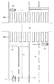
ここで、図4を参照して、上画角外れとなる距離(上画角外れ距離)Lzの算出方法について説明する。尚、図中のsは撮像面の上下方向の1/2サイズ、fは撮像面からの焦点距離、hは補助信号機23の撮像面の上下方向中央からの高さであり、上方の画角外れ(上画角外れ)の生じる距離Lzは、
Lz=(f・h/s)+f…(1)
から求めることができる。この場合、焦点距離fは短いため無視すれば、
Lz=f・h/s…(2)
となる。尚、図中のθは画角である。
Here, with reference to FIG. 4, a method of calculating a distance (upper angle off-angle distance) Lz that is out of the upper angle of view will be described. In the figure, s is a half size in the vertical direction of the imaging surface, f is a focal length from the imaging surface, h is a height from the vertical center of the imaging surface of the
Lz = (f · h / s) + f (1)
Can be obtained from In this case, since the focal length f is short, it can be ignored.
Lz = f · h / s (2)
It becomes. In the figure, θ is the angle of view.
同様に、横方向の画角外れ(横画角外れ)の生じる距離Lyは、上式(1),(2)の高さhを撮像面の幅方向中央からの横距離(補助信号機23の外側端部までの距離)wと読み替え、画像面の上下方向の1/2サイズsを画像面の幅方向の1/2サイズsと読み替えることで、(1’),(2')式のように求めることができる。 Similarly, the distance Ly in which the horizontal field angle deviation (horizontal field angle deviation) occurs is the horizontal distance from the center in the width direction of the imaging surface (the auxiliary signal device 23). (Distance to the outer end) w), and the half size s in the vertical direction of the image plane is read as half size s in the width direction of the image plane. Can be asking.
Ly=(f・w/s)+f…(1’)
Ly=f・w/s…(2’)
従って、メインカメラ2aの撮像面に結像された補助信号機23の画像に基づき撮像面の上下方向中央からの高さhを求めることで、上画角外れ距離Lzが求められ、撮像面の幅方向中央からの横距離wを求めることで、横画角外れ距離Lyを求めることができる。
Ly = (f · w / s) + f (1 ′)
Ly = f · w / s (2 ′)
Therefore, by obtaining the height h from the center in the vertical direction of the imaging surface based on the image of the
そして、上画角外れ距離Lzと横画角外れ距離Lyとを比較して、何れか長い方の距離、すなわち、早期に画角外れが生じる側の距離を真の画角外れ距離Lgとして設定する。 Then, the upper field angle deviation distance Lz and the horizontal field angle deviation distance Ly are compared, and the longer distance, that is, the distance on the side where the field angle deviation occurs earlier is set as the true field angle deviation distance Lg. To do.
上述した補助信号機23の高さは、画像認識処理部12で求めた自車両1から補助信号機23までの距離(補助信号機間距離)Ls(図6参照)に基づき、撮像面の1画素ピッチ当たりの実高さを求め、撮像面の上下方向中央から補助信号機23の上端までの画素数に1ピッチ当たりの実高さを掛けることで求めることができる。同様に、横距離wは、補助信号機間距離Ls(図6参照)に基づいて求めた撮像面の1画素ピッチ当たりの実横長さに、撮像面の幅方向中央から補助信号機23の外側端部までの画素数を掛けることで求めることができる。
The height of the
そして、信号機認識部14は、上述した画角外れ距離Lgに基づき、自車両1が画角外れ距離Lgに達したか否かを調べ、画角外れ距離Lgに達した後、補助信号機23に関する情報はクリアせず、継続的に推定させる。
Then, the traffic
上述した信号機認識部14での信号機認識処理は、具体的には、図2に示す信号機認識処理ルーチンに従って実行される。このルーチンは、車載カメラ2のフレームレートに対応して起動され、先ず、ステップS1で、追跡対象信号機記憶部に記憶されている補助信号機23の情報に基づき、前回のフレーム画像で認識した補助信号機23が、今回のフレーム画像でも認識されているか否かの信号機追跡処理を行い、ステップS2へ進み、今回のフレーム画像においても補助信号機23が認識されている場合、信号機追跡が継続していると判定し、ステップS11へジャンプする。又、今回のフレーム画像からは補助信号機23が認識されていない場合、ステップS3へ進み、ステップS3,S4で一時的なロストか、画角外れかを調べる。
Specifically, the traffic signal recognition process in the traffic
先ず、ステップS3では、追跡対象信号機である補助信号機23の設置位置を特定する高さhと横距離wとに基づき、上画角外れ距離Lzと横画角外れ距離Lyとを上述した(2),(2’)式から各々求め、何れか長い方の距離を真の画角外れ距離Lgとして設定する(Lg←max(Lz,Ly))。因みに、図7は自車両1の補助信号機間距離Lsが上画角外れ距離Lzに達した状態を示し、この状態から更に進むと、図8(a)に示すように、補助信号機23が上画角外れを生じる。この状態は、Lz>Lyであるため、真の画角外れ距離Lgは上画角外れ距離Lzで設定される(Lg←Lz)。尚、このステップS3での処理が、本発明の画角外れ距離算出手段に対応している。
First, in step S3, based on the height h and the lateral distance w that specify the installation position of the
そして、ステップS4へ進み、画像認識処理部12で求めた補助信号機間距離Lsと、真の画角外れ距離Lgとを比較する。そして、Ls≧Lgの場合、未だ、自車両1が画角外れ距離Lgに到達しておらず、一時的なロストと判定し、ステップS11へジャンプする。ステップS2或いはステップS4からステップS11へ進むと、画角外れポイントPiをクリアして(Pi←0)、ルーチンを抜ける。
Then, the process proceeds to step S4, where the auxiliary inter-signal device distance Ls obtained by the image
一方、ステップS4で、Ls<Lgと判定された場合、自車両1が画角外れ距離Lgに到達し、上画角外れ(図8(a)参照)、或いは横画角外れ(図8(b)参照)が生じているため、ステップS5へ進み、画角外れポイントPiをインクリメントし(Pi←Pi+1)、ステップS6へ進む。ステップS6では、画角外れポイントPiと予め設定されている画角外れ継続判定しきい値Poとを比較する。このる画角外れ継続判定しきい値Poは、自車両1が画角外れ距離Lgに到達した直後の過度状態における誤判定を防止するためのものであり、画角外れ継続判定しきい値Poは予め実験等から求めて設定されている。尚、本実施形態では、この画角外れ継続判定しきい値Poを所定フレーム数(例えば、フレームレート30[fps]場合、10程度)に対応する値に設定している。
On the other hand, if it is determined in step S4 that Ls <Lg, the
そして、Pi<Poの場合、画角外れ継続判定しきい値Poに達していないため、ルーチンを抜ける。一方、Pi≧Poの場合、補助信号機23は画角外れ状態にあると判定し、ステップS7へ進む。尚、このステップS4〜S6での処理が、本発明の画角外れ判定手段に対応している。
If Pi <Po, the routine is exited because the out-of-angle continuation determination threshold Po has not been reached. On the other hand, if Pi ≧ Po, it is determined that the
又、ステップS7へ進むと、追跡対象信号機記憶部に格納されている主信号機22の情報に基づき主信号機22が認識されているか否かを調べ、主信号機22が認識されていない場合、主信号機22の点灯している信号に基づいて補助信号機23の点灯している信号を設定することができないため、そのままルーチンを抜ける。
In step S7, it is checked whether or not the
一方、主信号機22が認識されている場合、ステップS8へ進み、追跡対象信号機記憶部に格納されている、画角外れとなった補助信号機23の情報を、画角外れ信号機記憶部へ移動させて、ステップS9へ進む。追跡対象信号機記憶部に格納されている両信号機22,23の情報は、他の制御処理においても読込まれるため、画角外れとなった補助信号機23の情報は、追跡対象信号機記憶部ではクリアして画角外れ信号機記憶部に記憶させるようにしている。尚、このステップS8での処理が、本発明の記憶情報移動手段に対応している。
On the other hand, if the
そして、ステップS9へ進むと、後述する画角外れ信号機推定処理ルーチンで求めた補助信号機間距離Lsの推定値(推定補助信号機間距離)Ls’に基づき、自車両1が画角外れとなった補助信号機23を通過したか否かを調べ、通過していない場合(0<Ls’)、そのままルーチンを抜ける。又、通過した場合(Ls’≦0)、ステップS10へ進み、画角外れ信号機記憶部に記憶されている画角外れとなっている補助信号機23の情報をクリアして、ルーチンを抜ける。このステップS9,S10での処理が、本発明の補助信号機情報クリア手段に対応している。
Then, when the process proceeds to step S9, the
この画角外れ信号機記憶部に記憶されている画角外れとなっている補助信号機23の情報は、図3に示す画角外れ信号機推定処理ルーチンにおいて逐次更新される。尚、このフローチャートでの処理が本発明の画角外れ信号機推定手段に対応している。
The information of the
このルーチンでは、先ず、ステップS21で自車両1の移動距離に基づき推定補助信号機間距離Ls’を設定する。すなわち、自車両1の移動距離はGPSを利用した測位情報に基づいて算出し、或いは車速センサで検出した車速に基づいて算出する。そして、補助信号機23が画角外れ距離Lgに到達したときから、この画角外れ距離Lgを基準に、この画角外れ距離Lgから移動距離を減算して推定補助信号機間距離Ls’を設定し、記憶させる。
In this routine, first, in step S21, the estimated auxiliary inter-signal device distance Ls' is set based on the moving distance of the
次いで、ステップS22へ進み、主信号機22の点灯している信号の灯火色を調べ、この灯火色を補助信号機23の灯火色として記憶させ、ルーチンを抜ける。この場合、信号の灯火色は、点灯している信号灯の色を検出することで行っても良いが、信号灯の配列は予め決められているため、各信号灯の輝度を検出し、高い輝度を示す信号灯の配列位置から点灯している信号の灯火色を認識するようにしても良い。
Next, the process proceeds to step S22, the lamp color of the signal that the
この画角外れ信号機記憶部に格納されている補助信号機23の推定補助信号機間距離Ls’及び点灯している信号灯色は、例えば運転支援制御システムにて読込まれ、推定補助信号機間距離Ls’に基づいて交差点までの距離を推定すると共に、点灯している信号灯色が黄色、或いは赤色の場合、必要な注意警報・自動ブレーキの作動等の運転支援制御が行われる。
The estimated auxiliary signal distance Ls ′ of the
以上の結果、図5に示すように、補助信号機23が画角外れとなった後であっても(時間t1)、推定補助信号機間距離Ls’は自車両1が補助信号機23を通過するまで、すなわち、自車両1が交差点に差し掛かるまで継続的に推定され、自車両1が補助信号機23を通過すると(時間t2)、その情報がクリアされ、主信号機22が最も近い追跡対象信号機として設定される。
As a result, as shown in FIG. 5, even after the
このように、本実施形態によれば、追跡対象信号機である補助信号機23の画像が車載カメラ2の画角から外れた後、追跡対象が主信号機22に切り替わる間の過度状態においては、補助信号機23の情報をクリアせず、追跡対象として継続的に推定させるようにしたので、例えば、運転支援制御システムでは、交差点手前における必要な注意警報・自動ブレーキの作動等の運転支援制御が、画角外れとなった補助信号機23の情報に基づいて行うことで、制御途中で追跡対象信号機が補助信号機から主信号機に切り替わることがなく、制御ハンチングが防止され、良好な制御性を得ることができる。
Thus, according to this embodiment, after the image of the
尚、本発明は、上述した実施形態に限るものではなく、主信号機と補助信号機とが交差点のない道路に設置されている場合であっても適用することができる。又、車載カメラ2はモノクロカメラであっても良い。
In addition, this invention is not restricted to embodiment mentioned above, Even if it is a case where the main signal apparatus and the auxiliary signal apparatus are installed in the road without an intersection, it is applicable. The in-
1…自車両、
2…車載カメラ、
11…画像認識ユニット、
14…信号機認識部、
15…記憶部、
22…主信号機、
23…補助信号機、
Lg…画角外れ距離、
Ls…補助信号機間距離、
Ls’…推定補助信号機間距離、
Ly…横画角外れ距離、
Lz…上画角外れ距離、
Pi…ポイント、
Po…画角外れ継続判定しきい値
1 ... own vehicle,
2… In-vehicle camera
11: Image recognition unit,
14 ... Traffic light recognition unit,
15 ... storage part,
22 ... main traffic light,
23 ... Auxiliary traffic light,
Lg ... out-of-field distance,
Ls: Distance between auxiliary traffic lights,
Ls ′: Estimated auxiliary inter-signal distance,
Ly: Horizontal angle off-angle distance,
Lz: Deflection distance of upper angle of view,
Pi ... point,
Po: Deflection continuation threshold value
Claims (4)
前記車載カメラで撮影した画像から主信号機、及び該主信号機よりも手前にあり該主信号機と同じ動作をする補助信号機を認識する信号機認識手段と、
認識した前記補助信号機の情報を格納する記憶手段と
を備え、
前記信号機認識手段は、
前記車載カメラで撮影した画像から撮像面上の前記補助信号機の設置位置を求め、該設置位置から画角外れとなる距離を算出する画角外れ距離算出手段と、
前記自車両と前記補助信号機との間の距離が前記画角外れとなる距離に達したか否かを判定する画角外れ判定手段と、
前記画角外れ判定手段で前記自車両と前記補助信号機との間の距離が前記画角外れとなる距離に達した後に画角外れと判定した場合、前記画角外れとなる距離を基準に前記自車両の移動距離に基づいて該自車両と前記補助信号機との間の距離を推定すると共に、前記主信号機の動作を該補助信号機の動作として設定する画角外れ信号機推定手段と
を備えることを特徴とする信号機認識装置。 An in-vehicle camera that captures the driving environment in front of the vehicle,
A traffic light recognition means for recognizing a main traffic light from an image photographed by the in-vehicle camera, and an auxiliary traffic light in front of the main traffic light and performing the same operation as the main traffic light;
Storage means for storing information of the recognized auxiliary signal device,
The traffic signal recognition means
An angle-of-view distance calculation unit that calculates an installation position of the auxiliary signal device on an imaging surface from an image captured by the in-vehicle camera, and calculates a distance that is out of an angle of view from the installation position;
An angle-of-view determination means for determining whether or not the distance between the host vehicle and the auxiliary traffic signal has reached a distance that is out of the angle of view;
If the distance between the auxiliary traffic and the vehicle at the angle of view out determination means determines that the angle deviates after reaching the distance at which said field angle out, the distance becoming the angle deviates to a reference together to estimate the distance between the auxiliary traffic and the vehicle based on the travel distance of the vehicle, that the operation of the main traffic signal and a field angle out traffic estimating means for setting the operation of the auxiliary signal unit A traffic light recognition device.
ことを特徴とする請求項1記載の信号機認識装置。 The angle-of-view determination unit determines that the angle of view is out of position after a predetermined time has elapsed after determining that the distance between the host vehicle and the auxiliary traffic signal has reached a distance that is out of the field of view. The traffic light recognition apparatus according to claim 1.
を更に備えることを特徴とする請求項1或いは2記載の信号機認識装置。 The traffic signal recognizing means includes distance information between the host vehicle and the auxiliary signal set by the out-of-angle signal estimating means and operation information of the auxiliary signal set in the storage means. 3. The traffic signal recognizing device according to claim 1, further comprising storage information moving means for moving from the storage unit to the off-angle signal signal storage unit.
を更に備えることを特徴とする請求項3記載の信号機認識装置。 The traffic signal recognizing means determines whether or not the distance information stored in the out-of-field signal storage unit is 0 or less, and clears the distance information and the operation information when the distance information is 0 or less. 4. The traffic signal recognizing device according to claim 3 , further comprising traffic signal information clearing means.
Priority Applications (1)
| Application Number | Priority Date | Filing Date | Title |
|---|---|---|---|
| JP2013271586A JP6194245B2 (en) | 2013-12-27 | 2013-12-27 | Traffic light recognition device |
Applications Claiming Priority (1)
| Application Number | Priority Date | Filing Date | Title |
|---|---|---|---|
| JP2013271586A JP6194245B2 (en) | 2013-12-27 | 2013-12-27 | Traffic light recognition device |
Publications (3)
| Publication Number | Publication Date |
|---|---|
| JP2015125708A JP2015125708A (en) | 2015-07-06 |
| JP2015125708A5 JP2015125708A5 (en) | 2016-11-10 |
| JP6194245B2 true JP6194245B2 (en) | 2017-09-06 |
Family
ID=53536344
Family Applications (1)
| Application Number | Title | Priority Date | Filing Date |
|---|---|---|---|
| JP2013271586A Active JP6194245B2 (en) | 2013-12-27 | 2013-12-27 | Traffic light recognition device |
Country Status (1)
| Country | Link |
|---|---|
| JP (1) | JP6194245B2 (en) |
Families Citing this family (6)
| Publication number | Priority date | Publication date | Assignee | Title |
|---|---|---|---|---|
| KR20160131129A (en) * | 2008-09-30 | 2016-11-15 | 솔베이(소시에떼아노님) | Process for the synthesis of halogenated cyclic compounds |
| JP6728634B2 (en) * | 2015-11-04 | 2020-07-22 | 株式会社リコー | Detecting device, detecting method and program |
| JP6723903B2 (en) * | 2016-11-15 | 2020-07-15 | 本田技研工業株式会社 | Vehicle control device and vehicle control method |
| KR102267262B1 (en) * | 2017-08-10 | 2021-06-22 | 현대자동차주식회사 | Active control method and apparatus for recognition of traffic lights of autonomous vehicles |
| JP7167880B2 (en) * | 2019-08-27 | 2022-11-09 | トヨタ自動車株式会社 | Stop line position estimation device and vehicle control system |
| CN114728657A (en) * | 2019-11-15 | 2022-07-08 | 日产自动车株式会社 | Vehicle control method and vehicle control device |
Family Cites Families (7)
| Publication number | Priority date | Publication date | Assignee | Title |
|---|---|---|---|---|
| JP2007257299A (en) * | 2006-03-23 | 2007-10-04 | Honda Motor Co Ltd | Vehicle external recognition system |
| JP4783431B2 (en) * | 2006-09-28 | 2011-09-28 | パイオニア株式会社 | Traffic information detection apparatus, traffic information detection method, traffic information detection program, and recording medium |
| JP4915281B2 (en) * | 2007-05-24 | 2012-04-11 | アイシン・エィ・ダブリュ株式会社 | Signal detection device, signal detection method and program |
| JP2010009235A (en) * | 2008-06-25 | 2010-01-14 | Toyota Motor Corp | Image display device |
| JP5621589B2 (en) * | 2010-12-28 | 2014-11-12 | アイシン・エィ・ダブリュ株式会社 | Navigation device, navigation method, and navigation program |
| JP5970858B2 (en) * | 2012-02-29 | 2016-08-17 | 日産自動車株式会社 | Vehicle control apparatus and vehicle control method |
| DE102012111740A1 (en) * | 2012-12-03 | 2014-06-05 | Continental Teves Ag & Co. Ohg | Method for supporting a traffic light phase assistant detecting a traffic light of a vehicle |
-
2013
- 2013-12-27 JP JP2013271586A patent/JP6194245B2/en active Active
Also Published As
| Publication number | Publication date |
|---|---|
| JP2015125708A (en) | 2015-07-06 |
Similar Documents
| Publication | Publication Date | Title |
|---|---|---|
| US10956757B2 (en) | Image processing device, outside recognition device | |
| JP6194245B2 (en) | Traffic light recognition device | |
| JP5863536B2 (en) | Outside monitoring device | |
| JP5276637B2 (en) | Lane estimation device | |
| JP6416293B2 (en) | Method of tracking a target vehicle approaching a car by a car camera system, a camera system, and a car | |
| US20150073705A1 (en) | Vehicle environment recognition apparatus | |
| US9740942B2 (en) | Moving object location/attitude angle estimation device and moving object location/attitude angle estimation method | |
| JP5421072B2 (en) | Approaching object detection system | |
| JP6787157B2 (en) | Vehicle control device | |
| CN111937002A (en) | Obstacle detection device, automatic braking device using obstacle detection device, obstacle detection method, and automatic braking method using obstacle detection method | |
| JPWO2013186903A1 (en) | Lane marking indicator, driving support system | |
| JP6331811B2 (en) | Signal detection device and signal detection method | |
| WO2019167531A1 (en) | Stereo camera device | |
| JP2009169847A (en) | Vehicle exterior monitoring device | |
| JP2007280132A (en) | Travel guide obstacle detector, and controller for vehicle | |
| US11610317B2 (en) | Image processor and image processing method | |
| CN110949254A (en) | Vehicle running environment detection device and running control system | |
| JP2008225822A (en) | Road partition line detection device | |
| JP2011033594A (en) | Distance calculation device for vehicle | |
| KR101511586B1 (en) | Apparatus and method for controlling vehicle by detection of tunnel | |
| JP2006344133A (en) | Road division line detector | |
| JP2009186301A (en) | Object detection device for vehicle | |
| JP6200780B2 (en) | Lane recognition determination device | |
| JP6174884B2 (en) | Outside environment recognition device and outside environment recognition method | |
| JP5652374B2 (en) | Vehicle headlamp control device |
Legal Events
| Date | Code | Title | Description |
|---|---|---|---|
| A521 | Request for written amendment filed |
Free format text: JAPANESE INTERMEDIATE CODE: A523 Effective date: 20160926 |
|
| A621 | Written request for application examination |
Free format text: JAPANESE INTERMEDIATE CODE: A621 Effective date: 20160926 |
|
| A977 | Report on retrieval |
Free format text: JAPANESE INTERMEDIATE CODE: A971007 Effective date: 20170706 |
|
| TRDD | Decision of grant or rejection written | ||
| A01 | Written decision to grant a patent or to grant a registration (utility model) |
Free format text: JAPANESE INTERMEDIATE CODE: A01 Effective date: 20170718 |
|
| A61 | First payment of annual fees (during grant procedure) |
Free format text: JAPANESE INTERMEDIATE CODE: A61 Effective date: 20170814 |
|
| R150 | Certificate of patent or registration of utility model |
Ref document number: 6194245 Country of ref document: JP Free format text: JAPANESE INTERMEDIATE CODE: R150 |
|
| R250 | Receipt of annual fees |
Free format text: JAPANESE INTERMEDIATE CODE: R250 |
|
| R250 | Receipt of annual fees |
Free format text: JAPANESE INTERMEDIATE CODE: R250 |
|
| R250 | Receipt of annual fees |
Free format text: JAPANESE INTERMEDIATE CODE: R250 |
|
| R250 | Receipt of annual fees |
Free format text: JAPANESE INTERMEDIATE CODE: R250 |